1
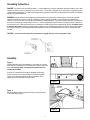
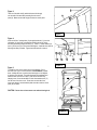
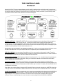
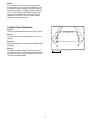
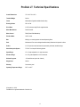
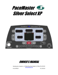
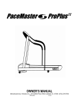
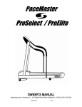
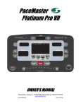
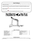
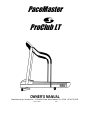
PaceMaster
ProClub LT
OWNER’S MANUAL
Manufactured by: Aerobics Inc., 34 Fairfield Place West Caldwell, NJ 07006 (973) 276-9700
PCLT.DOC
2/03
TABLE OF CONTENTS
INTRODUCTION
2
IMPORTANT SAFETY INSTRUCTIONS
3
ASSEMBLY INSTRUCTIONS
Installation Requirements
Unpacking Your Treadmill
Tool Required for Assembly
Grounding Instructions
Assembly
Testing Your Treadmill
4-7
4
4
4
5
5-6
7
THE CONTROL PANEL
8-9
OPERATING INSTRUCTIONS
Setting Your Weight
Metric Units
Quick Start
Manual Operation
Preset Workouts
Preset Workouts Course Specifications
10-12
10
10
10
11
11
12
EXCLUSIVE ProClub LT FEATURES
Aerobic Points
13
13
CARE AND MAINTENANCE
Deck and Tread Belt Cleaning
Lubrication
Centering the Tread Belt
14
14
14
14
TROUBLE SHOOTING
Electronic Error Codes
Hesitation of the Belt
Drive Belt Tension Adjustment
Tread Belt Tension Adjustment
15-16
15
15
15-16
16
ProClub LT TECHNICAL SPECIFICATIONS
17
1
INTRODUCTION
Congratulations on your commitment toward better health and fitness!
The staff at Aerobics Inc. would like to thank you for purchasing a PaceMaster treadmill. Not only did you buy one of
the highest quality treadmills on the market; you also received excellent value for your dollar. PaceMaster treadmills
have been rated “BEST BUY” by more nationally recognized publications than any other treadmill.
Aerobics Inc. has been designing and manufacturing treadmills since 1968. We are a family-owned and operated
business, comprised of fitness enthusiasts who are committed to providing consumers with outstanding quality
treadmills at affordable prices. All PaceMaster treadmills are made in the USA.
Your PaceMaster ProClub LT has a wide variety of features to assist you in reaching your fitness goals. Please read
this manual in its entirety so you will be thoroughly acquainted with assembly, operation and maintenance
information.
About This Manual
It is highly recommended that you read this manual in its entirety before attempting to use your PaceMaster
treadmill. It contains information to familiarize you with assembly, basic operations, preset workouts and custom
programming.
For your safety, and the protection of your treadmill, we have included warnings and other valuable information
throughout this manual. The information will be in bold type and marked by the following symbols. Be absolutely
sure to thoroughly read and understand this information.
CAUTION, WARNING or DANGER indicates important safety warnings. Failure to read and understand these
warnings may result in personal injury or damage to your treadmill. TIP indicates useful suggestions to keep in
mind while using your PaceMaster treadmill.
2
IMPORTANT SAFETY INSTRUCTIONS
Read these instructions before using your treadmill
CAUTION: Before starting any exercise program, contact your personal physician and have a complete physical. This is highly
recommended if you have not been on a regular exercise program within the last year or are over 35 years of age or are overweight.
CAUTION: If at any time during your exercise program you find the exercise abnormally difficult or you encounter dizziness, feel faint,
experience chest pains, feel as if your heart may be skipping beats, you experience forced, heavy breathing after minimal exercise or severe
pain in your legs, ankles, knees, etc., STOP EXERCISING and consult your physician.
WARNING: To reduce the risk of burns, fire, electrical shock or injury:
• Never operate your PaceMaster treadmill without clipping the magnetic safety key to your clothing at waist level.
• Your PaceMaster treadmill is not designed for use by children under the age of 18 without strict parental supervision.
• Close supervision is necessary when the treadmill is used by or near children or disabled persons.
• Use your PaceMaster treadmill only for its intended use as described in this manual. Do not use accessories or attachments not
recommended by Aerobics, Inc.
• Never operate your PaceMaster treadmill if it has a damaged cord or plug, if it is not operating properly, if it has been dropped or
damaged or if it has been immersed in water. Should any of these occur, contact your authorized PaceMaster retailer or service
center for examination or repair.
• Keep the cord away from heated surfaces.
• Never drop or insert any object into any opening on the treadmill.
• Do not use outdoors.
• Always unplug your PaceMaster treadmill during an electrical storm or during extended periods of non-use.
• Do not operate where aerosol (spray) products are being used or where oxygen is being administered.
• Position the treadmill with a minimum of 4 feet of clearance between the rear of the treadmill and any wall or obstruction.
• Do not allow anyone to reach under or be too near your PaceMaster while it is in use.
• Do not attempt to mount or dismount the tread belt while it is running.
• Never allow more than one person on your PaceMaster treadmill at any time.
• Never move the treadmill while it is plugged into the electrical outlet.
• When you are finished exercising, leave your PaceMaster treadmill in a non-elevated position to avoid toys and other objects from
becoming trapped beneath.
• Wear appropriate running or walking shoes and attire while exercising.
• The treadmill should be turned off after each use by removing the safety magnetic key.
• Never apply lubricant to the belt and deck. It is permanently lubricated at the factory and is maintenance free.
3
ASSEMBLY INSTRUCTIONS
Installation Requirements
Your ProClub LT should be installed indoors on a flat, level surface near a 120Volt/ 15Amp outlet. PaceMaster requires a dedicated, nonswitched outlet that is not part of a GFI (Ground Fault Interrupter) circuit, preferably no more than 5 feet from the outlet to eliminate the need
for an extension cord. You must have a minimum of 4 feet of clearance between the rear of the treadmill and any wall or obstruction.
TIP: If you are installing your ProClub LT on a carpeted surface, use a treadmill mat or a scrap piece of carpet underneath the treadmill to
avoid soiling of the carpet. Deep pile carpet is not recommended.
Unpacking Your Treadmill
The PaceMaster treadmill is packed in five pieces:
• Frame assembly
• Front handlebar assembly with Control Panel
• Two side rails
• Motor cover
• Hardware package
Before assembling your treadmill, open the hardware package and verify that you have the following items:
Two black side rail brackets
Two #8 x ½” black sheet metal screws
Two 1” fender washers
3/16” Allen wrench
Four 1/4-20 x 3.5" black carriage bolt
Magnetic safety key with garment clip
Two 1/4-20 x 4” black carriage bolt
Owner’s Manual
Six 1/4-20 kep nuts
Warranty registration card
If any parts are missing, contact the authorized PaceMaster retailer where you purchased your PaceMaster treadmill.
Tools Required for Assembly
•
•
•
3/16" Allen wrench (supplied)
7/16” combination wrench
Phillips head screwdriver
4
Grounding Instructions
DANGER: This product must be properly grounded. If it should malfunction or become inoperable, grounding provides a path of least
resistance for electric current to reduce the risk of electric shock. This product is equipped with a cord having an equipment-grounding
conductor and a grounding plug. The plug must be plugged into an appropriate outlet that is properly installed and grounded in accordance
with all local codes and ordinances.
WARNING: Improper connection of the equipment grounding-conductor can result in a risk of electrical shock. Check with a qualified
electrician or serviceman if you are in doubt as to whether the product is properly grounded. Do not modify the plug provided with the
product. If it will not fit the outlet, have a proper outlet installed by a qualified electrician. This product is rated for more than 15 amperes and
is for use on a circuit having a nominal rating of 120 volts. It is factory equipped with a specific electric cord and plug to permit connection to
a proper electric circuit. Make sure that the product is connected to an outlet having the same configuration as the plug. No adapter should
be used with this product. Attempting to bypass it with an adapter or in any way defeating its purpose can result in a serious shock hazard.
As a safety precaution you should unplug the treadmill during electrical storms or if the treadmill will not be in use for periods greater than
one week.
CAUTION: If you need to use an extension cord it must be a 14 gauge, three wire cord, no longer than 12 feet.
Assembly
Figure 1:
Carefully place the bottom of the handlebar (1) on the frame (2) so the two
holes in the plate at the bottom of the handlebar line up with the holes in the
frame. Be extremely careful not to damage the speed sensor while
installing the handlebar.
Insert the 3.5” carriage bolts (3) through the handlebar and the frame.
Install a 1/4-20 kep nut (4) to each carriage bolt to keep the handlebar
in place. Follow the same procedure for the other handlebar. Do not
tighten any nuts until both sides are bolted in place.
Figure 1
Figure 2:
With the handlebar in place, plug the wire harness (5) into the socket (6)
on the power supply board (7).
Figure 2
5
Figure 3:
Take one of the side rails (8) and slide the end with the grip
over the end of the steel tube protruding from the control
panel (9). Make sure the side rail grip touches the control panel.
Figure 3
Figure 4:
Insert one of the 4” carriage bolts (10) through the side rail (11), the side
rail bracket (12) (the foam on the bracket should be at the top, facing
the frame) and finally through the frame (13) . Install a 1” fender washer (14)
and a ¼-20 kep nut (15) to the bolt and hand tighten. Install the other side rail
following the same procedure. Tighten both side rails with a wrench.
Figure 4
Figure 5:
To install the motor cover, stand in front of the treadmill. Pick up
the motor cover (16) so it is level and the word PaceMaster is upside
down. Holding the motor cover level and waist high, tilt it 45 degrees
by lowering your left hand. Then slide it between the handlebars and
lower the motor cover until it is level. Lower the cover all the way,
keeping it level. Screw the two #8x1/2” black sheet metal screws (17)
into the front of the motor cover. Press down on each side of the
motor cover where it meets the black plastic shrouds to lock the Velcro
pads (18) into place.
CAUTION: Do not raise or lower motor cover without it being level.
Figure 5
6
Testing Your Treadmill
Your ProClub LT has been adjusted and tested at the factory. However, due to changes that can occur during shipment, it should be tested
prior to use. Once you have assembled your treadmill and it is located where it will be used, proceed as follows. (Do not make any
adjustments unless necessary.) For the purpose of this test, DO NOT stand on the tread belt. Once tested, always start and finish on
the tread belt.
Step One:
After your treadmill is in place and plugged in to the wall outlet, insert the magnetic safety key into the recess on the control panel.
Step Two:
You will see the number 150 in the INCLINE display window and the SET WEIGHT indicator light will be blinking. This is where the user’s
weight is adjusted. The default weight set at the factory is 150 lbs. For the purpose of this test, it is not necessary to enter your actual weight
at this time.
Step Three:
Set the workout speed by pressing the SPEED + button until the SPEED display window shows 2.5 mph.
Step Four:
Press the START/STOP button. Within a few seconds, the tread belt will begin to move. If the tread belt does not move, or the treadmill
stops after a few seconds and displays an error code, make a note of the error code and contact the authorized PaceMaster retailer where
you purchased your treadmill.
Step Five:
After the treadmill has reached 2.5 mph, observe the tread belt to make sure it is reasonably centered. If the tread belt is not centered,
Immediately press the STOP button and refer to the CARE and MAINTENANCE section of this manual, under Centering The Tread Belt.
Once the tread belt is centered, run the treadmill at 2.5 mph for 2 minutes to be sure it remains centered.
Step Six:
To test the elevation, the tread belt must be moving. Press the arrow up button to raise the elevation to 3% incline. The elevation will be
displayed in the INCLINE display window. Once it reaches 3%, press the down arrow button to reduce the incline to 0%. If the treadmill
does not elevate, or stops after a few seconds and displays an error code, make a note of the error code and contact the authorized
PaceMaster retailer where you purchased your treadmill.
7
THE CONTROL PANEL
ProClub LT
Although the ProClub LT has many advanced features to provide versatility in meeting exercise needs, basic operation is extremely easy.
Basic operation involves setting your TIME and SPEED goals, then pressing the START button. Your ProClub LT will gradually accelerate to
the set speed, maintain that speed until you press the stop button to end the workout. During your exercise, your time remaining, current
speed, distance traveled, calories burned, and Aerobic Points earned are displayed.
MAGNETIC SAFETY KEY - The MAGNETIC SAFETY KEY, with its red cord and garment clip, is a safety feature. Before you begin your
workout, clip the safety cord to your clothing at waist level. This safety key provides a means of powering down the treadmill in an
emergency situation. It is also the ON/OFF switch. The ProClub LT will not operate unless the MAGNETIC SAFETY KEY is engaged. To
turn your ProClub LT on, insert the MAGNETIC SAFETY KEY into the recess on the control panel. During exercise, an emergency stop can
be made at any time by pulling on the cord to release the key from its slot.
Using the key to stop your ProClub LT is an emergency procedure only! To end your exercise routine, press the STOP button or allow
the timer to count down to zero. Once your ProClub LT has come to a complete stop, remove the MAGNETIC SAFETY KEY.
TIME DISPLAY WINDOW – If you have chosen a Preset Workout a 2.5 min. warm up and/or cool down mode is included. Time will be
displayed as a 2.5-minute countdown for the warm up phase, a countdown for the main exercise phase and then a 2.5-minute countdown for
the cool down phase. In Quick Start, the TIME DISPLAY WINDOW shows elapsed time.
DISTANCE DISPLAY WINDOW - Before beginning your Manual or Preset Workouts (P1 – P4), this window displays the total distance you
will exercise based on the workout time or level entered. During your Preset Workouts, Manual or Quick Start modes, the DISTANCE
DISPLAY WINDOW shows the distance thus far.
DATA DISPLAY WINDOW – When selecting a Preset Workout, the program and level numbers will appear in the DATA DISPLAY
WINDOW. At the end of your workout, you will see the total caloric expenditure when the CALORIES indicator light will be illuminated. You
will also see the total Aerobic Points accumulated when the POINTS indicator light is illuminated. For details, refer to the AEROBIC POINTS
SYSTEM section in this manual.
When in Metric units operation (kilogram, kilometers and KPH) instead of English units (pounds, miles and mph), the METRIC indicator light
in the upper left corner of the DATA DISPLAY WINDOW will be illuminated. For details, refer to the METRIC UNITS section in this manual.
INCLINE DISPLAY WINDOW - When the magnetic safety key is inserted, the last entered weight will be displayed in the INCLINE DISPLAY
WINDOW and the WEIGHT indicator light will blink. To adjust the weight, press the INCLINE arrow up or down buttons until the desired
weight is displayed. Prior to beginning a Preset Workout, the maximum incline will be displayed and the MAX indicator light will be
illuminated. Once your workout has begun, the current incline will be constantly displayed in the INCLINE DISPLAY WINDOW.
8
INCLINE UP AND DOWN ARROWS - Incline is adjustable from 0% to 15% in 0.5% increments. You can increase or decrease the incline
by pressing the INCLINE UP OR DOWN ARROW buttons at any time during your workout. At the end of your workout, it is recommended
that the elevation setting be returned to 0%.
START/STOP - Press this button to start or stop your program.
SPEED DISPLAY WINDOW – Prior to beginning a Preset Workout, the maximum speed will be displayed here. The MAX indicator light will
be illuminated. Once your workout has begun, the current speed is constantly displayed in the SPEED DISPLAY WINDOW.
By pressing the PACE button, the current pace will be displayed. The PACE indicator light will be illuminated.
When in Metric units operation (kilogram, kilometers and KPH) instead of English units (pounds, miles and MPH), the METRIC indicator light
in the upper left corner of the DATA DISPLAY WINDOW will be illuminated. For details, refer to the METRIC UNITS section in this manual.
SPEED + AND – BUTTONS - Speed is adjustable from 0.7 to 12 mph in 0.1 mph increments. You can adjust your speed by pressing these
buttons to increase or decrease at any time during exercise in any program.
SELECT BUTTON – Press the SELECT button until the desired program is displayed in the DATA display window. For details, refer to the
PRESET WORKOUTS section in this manual.
LEVEL + / LEVEL – BUTTONS – Once the desired Preset Workout is chosen, press these buttons for the desired level of intensity. The
level will be displayed in the DATA display window next to the program number. For details, refer to the PRESET WORKOUTS COURSE
SPECIFICATIONS section in this manual.
9
OPERATING INSTRUCTIONS
Initially, you may want to keep both hands on the side rails until you feel comfortable walking on your ProClub LT. Once comfortable, try
removing your hands to let them swing naturally, as you would walking outdoors. Always hold on to the side rail or front handle bar with one
hand when operating the buttons of the control panel.
THE FIRST STEP
Stand on the center of the treadmill belt. Attach the garment clip on the end of the magnetic safety key to your clothing at waist level. Insert
the safety key into the recess on the control panel keyboard.
SETTING YOUR WEIGHT
Your ProClub LT calculates caloric expenditure based on the formula developed by the American College of Sports Medicine. To ensure
accuracy, your weight is required. The default weight of 150 lbs. has been set at the factory. It is displayed in the INCLINE display window
and the SET WEIGHT indicator light will blink for 5 seconds. By pressing the INCLINE up or down arrow buttons, you will increase or
decrease the weight. When the treadmill has accepted the weight, this is the number that will appear each time the treadmill is powered up
until it is changed again. If no change is made the treadmill will default to the previously set weight.
METRIC UNITS
To select operation in Metric units (kilograms, kilometers and KPH) instead of English units (pounds, miles and MPH) insert the magnetic
safety key. While the SET WEIGHT indicator light is blinking, press and hold the PACE button in the SPEED display window until the
METRIC indicator light in the left corner of the DATA display window is illuminated.
QUICK START
Once you have entered your weight, pressing Start allows you to begin your workout by pressing one button. You control the speed and
incline.
To begin using :
Step One:
Stand on the running belt and attach the garment clip on the end of the magnetic safety key to your clothing. Insert the safety key into its
recess on the control panel.
TIP: If the magnetic safety key was not removed since the treadmill was last used, skip to Step Three
Step Two:
Enter your weight as described in the OPERATING INSTRUCTIONS, SETTING YOUR WEIGHT.
Step Three:
Press START and your ProClub LT will gradually accelerate until it reaches 1 mph. Or you can enter a specific starting speed prior to
pressing START and the treadmill will gradually accelerate until it reaches your desired speed.
• Adjust the speed at any time during your workout by pressing the SPEED + and – buttons. Speed will adjust in 0.1 mph increments
• Add incline at any time during your workout by pressing the incline up and down arrow buttons. Elevation will adjust in 0.5% increments.
To end your workout, press the STOP button. The treadmill will display the total time, calories expended, Aerobic Points earned and
distance.
If a problem should occur, your ProClub LT can be stopped quickly by pulling on the magnetic safety cord to dislodge the key from the
control panel. The treadmill will stop a bit more abruptly, but still gently enough to prevent you from being injured. This is an emergency
procedure only and should not be used as the normal stopping procedure.
10
MANUAL OPERATION
Manual operation allows you to choose the length of time and the degree of intensity of your workout. You can
make speed and incline adjustments at any time during the program.
To begin using :
Step One:
Stand on the running belt and attach the garment clip on the end of the magnetic safety key to your clothing. Insert the safety key into its
recess on the control panel. If the magnetic safety key was not removed since the treadmill was last used, skip to Step Three.
Step Two:
Enter your weight as described in the OPERATING INSTRUCTIONS, SETTING YOUR WEIGHT.
Step Three:
Enter the starting speed by pressing the SPEED + button until the desired speed appears in the SPEED display window. Enter the starting
elevation by pressing the INCLINE Λ button until the desired grade is displayed in the INCLINE display window.
• Adjust the speed at any time during your workout by pressing the SPEED + and – buttons. Speed will adjust in 0.1 mph increments
• Add incline at any time during your workout by pressing the INCLINE Λ and V buttons. Elevation will adjust in 0.5% increments.
Step Four:
Enter the workout time by pressing the LEVEL + button until the desired time appears in the TIME display window.
Step Five:
Press START and the treadmill will accelerate until it reaches the entered speed. To end your workout, either allow the timer to count down
to zero or press the STOP button. The treadmill will display total time, calories expended, Aerobic Points earned and distance.
If a problem should occur, your ProClub LT can be stopped quickly by pulling on the magnetic safety cord to dislodge the key from the
control panel. The treadmill will stop a bit more abruptly, but still gently enough to prevent you from being injured. This is an emergency
procedure only and should not be used as the normal stopping procedure.
PRESET WORKOUTS
To assist you in reaching your fitness goals, your ProClub LT comes with 4 Preset workouts- Fat Burn, Cardio, Endurance and Interval.
These specifically designed courses each offer 9 different levels of intensity, giving you 36 different workout possibilities. During your
workout, you will be alerted to any speed and/or elevation changes in the program with 3 beeps and a flashing speed and/or incline display,
then the new speed and/or incline will be displayed
To begin using a PRESET WORKOUT:
Step One:
Stand on the running belt and attach the garment clip on the end of the magnetic safety key to your clothing. Insert the safety key into its
recess on the control panel. If the magnetic safety key was not removed since the treadmill was last used, skip to Step Three
Step Two:
Enter your weight as described in the OPERATING INSTRUCTIONS, SETTING YOUR WEIGHT.
Step Three:
Press the SELECT button until the indicator light next to the desired program is illuminated. The program number will be displayed in the
DATA display window. Press the + LEVEL button to adjust the level of intensity. The level will be displayed in the DATA display window
next to the program number. The maximum speed for that level will be displayed in the SPEED display window and the maximum incline for
that level will be displayed in the INCLINE display window. The MAX indicator lights will also be illuminated. You can adjust the level of
intensity at any time during your workout by pressing the + LEVEL or LEVEL - buttons.
Step Four:
A 2.5 minute Warm up and a 2.5 minute cool down period are automatically added to all the preset workouts.
Step Five:
Press START and your ProClub LT will gradually accelerate. Your workout will end when the timer has counted down to zero or the STOP
button is pressed. Total time, calories expended, Aerobic Points earned and total distance will be displayed.
If a problem should occur, your ProClub LT can be stopped quickly by pulling on the magnetic safety cord to dislodge the key from the
Control Panel. The treadmill will stop a bit more abruptly, but still gently enough to prevent you from being injured. This is an emergency
procedure only and should not be used as the normal stopping procedure.
11
12
EXCLUSIVE ProClub LT FEATURES
Aerobic Points
One of the main reasons people stop exercising is because they don’t see the physical changes they expected. Results, however, can only
be realized when you are training properly. For this reason, the Aerobic Point System has been incorporated into the design of PaceMaster
treadmills since 1968.
The Aerobic Point System was developed by Dr. Kenneth Cooper, the Father of Aerobics and renowned founder of The Cooper Aerobics
Center in Dallas, TX, to measure the aerobic benefit of the workout. Dr. Cooper’s formula compares the energy costs of aerobic activity
from the mathematical relationships between the oxygen expenditures assigned to each exercise at a given intensity and duration. This
formula is built into the ProClub LT computer to automatically calculate the number of AEROBIC POINTS you earn for each workout
Dr. Cooper states in his book, The Aerobics Program For Total Well Being; “The main idea of this system is that, in order to stay in good
shape and move toward a goal of total well-being, a person must earn a certain number of points each week by doing a certain amount of
aerobic exercise.” His research has determined that a man should work up to a minimum of 32 points per week and a woman should work
up to a minimum of 27 points per week. The number of weekly points you earn correlates with your level of fitness. The fitness categories
are:
Average Points Per Week
Classification
Men
Women
Very Poor
Less than 10
Less than 8
Poor
10-20
8-15
Fair
21-31
16-26
Good
32-50
27-40
Excellent
51-74
41-64
Superior
75+
65+
If you have not been on a regular exercise program, it is highly recommended that you gradually work up to your desired fitness category
and then develop a maintenance program.
13
Care and Maintenance
The following section describes necessary maintenance for your ProClub LT treadmill. This maintenance is the responsibility of the
purchaser and is not covered under our warranty. Failure to perform this necessary maintenance could result in damage to your treadmill.
CAUTION: Be sure to unplug your treadmill before attempting any cleaning or maintenance.
Deck and Tread Belt Cleaning
The running belt on your ProClub LT rides on a low friction, maintenance-free deck. Proper operation will be jeopardized if any water, dirt,
solvents, fluids or abrasive materials come between the tread belt and the deck. For this reason, extra care must be used in keeping the belt
clean. Use a soft, damp cloth to remove dust, dirt and other substances from the area between the belt and the side of the machine. Do not
clean the tread belt by turning on the treadmill.
Lubrication
The motor and roller bearings are sealed for maintenance free operation and require no lubrication. The deck and tread belt are lubricated at
the factory and are also maintenance free. Any attempt to lubricate underneath the running belt will result in damage, especially if silicone or
any other lubricant is used.
The side rails are made of steel. By occasionally applying a coat of automotive wax to them will help prevent rusting.
Centering the Tread Belt
To improve belt life, the belt should be reasonably centered. To center the belt, walk on the treadmill at 2.5 mph for a few minutes.
Determine whether the belt drifts too far to the left or right side. If adjustments are required, stop the treadmill and follow the steps listed
below. Never make adjustments while the tread belt is moving.
WARNING: Never make any unnecessary adjustments.
CAUTION: The power must be turned off before making adjustments.
Step One:
If the belt is drifting to the left, using a 3/16” Allen
wrench, turn the left-hand adjustment bolt (1) a quarter
turn clockwise and the right-hand adjustment bolt (2) a
quarter turn counter-clockwise.
If the belt is drifting to the right, using a 3/16” Allen
wrench, turn the right-hand adjustment bolt (2) a quarter
turn clockwise and the left-hand adjustment bolt (1) a
quarter turn counter-clockwise.
Step Two:
Walk on the belt for 1 minute, observing belt tracking.
If the belt moves to one side, repeat step 1.
Figure 6
14
TROUBLESHOOTING
Electronic Error Codes
Your self-diagnostic ProClub LT treadmill has built in sensors that will determine the precise reason for a problem. If the onboard computer
detects a problem, an error code will be displayed. If an error code appears during operation of your treadmill, do the following:
•
•
•
•
Make a note of the error code number.
Obtain your serial number, located on the front of the treadmill approximately 10-12 inches to the left of the power cord.
Write down which mode of operation you were using, the speed and incline that were set and if you were pressing any
buttons at the time.
Contact the PaceMaster dealer where you purchased your treadmill. If you have moved or need the name of the local dealer,
visit our website at www.pacemaster.com <http://www.pacemaster.com> and choose the dealer locater to find this
information.
Hesitation of the Tread belt
Hesitation of the tread belt usually indicates slippage of either the tread belt (the belt you walk on) or the drive belt (the belt connecting the
drive roller to the motor). To determine which of these belts is slipping, first adjust the drive belt tension and test to see if the slippage stops.
If the hesitation is not corrected than the tread belt tension needs adjustment.
CAUTION: The power must be turned off before making adjustments.
Drive Belt Tension Adjustment
Step One:
Use a Phillips head screwdriver to remove the 2 screws
that hold the front of the motor cover in place and remove
the motor cover.
Step Two:
Locate the four motor mount screws (1) as shown in the
diagram and loosen them each two turns each using the 3/16"
allen wrench.
Figure 7
Step Three:
Locate the drive belt adjustment screw (2) in the lower
front end of the treadmill. Insert the allen wrench into the drive
belt adjustment screw. Turn the screw 1/2 turn clockwise.
Step Four:
Complete the adjustment by tightening the four motor mount
screws (1).
Step Five:
Walk on the treadmill to determine if the slippage is decreased
or eliminated.
Figure 8
15
Step Six:
If no improvement is observed, the hesitation may be caused
by a loose tread belt - see "Tread belt tension adjustment" below.
If improvement is noticed but slippage is still present, repeat the
procedure and test again. If you tighten the drive belt adjustment
screw 1 1/2 turns and there is still hesitation (slippage) contact
your authorized PaceMaster dealer. Tightening the drive belt
adjustment screw more than 1 1/2 turns can result in bearing
damage to the motor and/or drive roller.
Tread Belt Tension Adjustment
Step One:
Locate the two tread belt adjustment screws (3) and (4) as shown.
Step Two:
Turn both the left and right tread belt adjustment screws 1/2 turn
clockwise.
Step Three:
Walk on the treadmill to see if the adjustment you made decreased
the slippage.
Step Four:
If a significant decrease in slippage was observed, go to step 2.
If you tighten the tread belt 1 1/2 turns per side and slippage is still
present, do not continue to adjust the tread belt tension. Contact
your authorized PaceMaster dealer.
Figure 9
16
ProClub LT Technical Specifications
Overall Dimensions
72”L x 30.5” W x 54”H
Treadmill Weight
200 lbs.
Frame
Welded aircraft grade extruded aluminum alloy
Running Surface
58”L x 20”W
Drive Motor
3.0 HP continuous duty DC with angled brushes
Motor Manufacturer
Pacific Scientific
Motor Control
PWM (Pulse Width Modulation)
Elevation Motor
1000 lb. thrust
Belt
Multi-ply, no stretch polyester with static dispersing fibers
Deck
Maintenance Free custom designed medium density fiberboard with phenolic surface
Rollers
2.5” OD precision machined steel with permanently lubricated, sealed bearings
Shock Absorption System
Tri-Flex™ Low Impact Cushioning System
Speed Range
0.7 to 12mph adjustable in 0.1 mph increments
Elevation Range
0 to 15% grade adjustable in 0.5% increments
Workout Programs
4 Preset Workouts (each with 9 levels)
Weight Limit
350 lbs.
Warranty
See warranty card
Operating Temperature Range
50º F to 100º F
© Aerobics, Inc. 2000
PaceMaster is a registered trademark of Aerobics Inc.
17