1
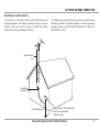
Collage
Media and Intercom System
Installation Manual
SAFETY INSTRUCTIONS
5. Water and Moisture - The appliance should
WARNING: TO REDUCE THE RISK OF FIRE OR ELECTRIC SHOCK,
DO NOT EXPOSE THIS APPLIANCE TO RAIN OR MOISTURE
CAUTION: TO REDUCE THE RISK OF ELECTRIC SHOCK, DO NOT
REMOVE THE COVER. NO USER-SERVICEABLE PARTS INSIDE.
REFER SERVICING TO QUALIFIED SERVICE PERSONNEL.
The lightning flash with arrowhead symbol, within an
equilateral triangle, is intended to alert the user to the presence
of uninsulated dangerous voltage within the product’s
enclosure that may be of sufficient magnitude to constitute a
risk of electric shock to persons.
The exclamation point within an equilateral triangle is
intended to alert the user to the presence of important
operating and maintenance (servicing) instructions in the
literature accompanying the appliance.
CAUTION: HIGH VOLTAGE
The high voltage back box, power pocket and power
supply are to be installed and connected by licensed
and qualified electricians ONLY. All wiring must be
done in accordance with the National Electric Code.
All wiring must comply with all local electrical codes.
All back box and power pocket installation must
comply with all local fire codes.
Safety Instructions
not be used near water; for example, near a
bathtub, washbowl, kitchen sink, laundry tub,
in a wet basement, or near a swimming pool.
The apparatus shall not be exposed to dripping
or splashing liquids and no objects filled with
liquids, such as vases, shall be placed on the
apparatus.
6. Wall Mounting - The appliance should be
mounted to a wall only as recommended by the
manufacturer.
7. Ventilation - The appliance should be situated
so that its location or position does not interfere
with its proper ventilation. For example, the
appliance should not be situated on a bed,
sofa, rug, or similar surface that may block
the ventilation openings, or placed in a builtin installation, such as a bookcase or cabinet
that may impede the flow of air through the
ventilation openings.
appliance should be unplugged from the outlet
when left unused for a long period of time.
To remove all power (supply mains) from the
appliance, remove the plug from the wall outlet.
13. Object and Liquid Entry - Care should be taken
so that objects do not fall and liquids are not
spilled into the enclosure through the openings.
14. Cleaning - The appliance should be cleaned only
as recommended by the manufacturer.
15. Damage Requiring Service - The appliance
should be serviced by qualified service personnel
when: A) The power supply cord or the plug has
been damaged; or B) Objects have fallen, liquid
has been spilled into the appliance.
16. Servicing - The user should not attempt to service
from heat sources such as radiators, heat
registers, stoves, or other appliances (including
amplifiers) that produce heat.
9. Power Sources - The appliance should be
connected to a power supply only of the type
described in the operating instructions or as
marked on the appliance.
2. Retain Instructions - The safety and operating
10. Grounding or Polarization - Precaution should
3. Heed Warnings - All warnings on the appliance in
11. Power Cord Protection - Power supply cords
instructions should be read before the appliance
is operated.
instructions should be retained for future
reference.
the operating instructions should be followed.
4. Follow Instructions - All operating and user
2
12. Non-Use Periods - The power cord of the
8. Heat - The appliance should be situated away
1. Read Instructions - All the safety and operating
instructions should be followed.
cords at plugs, receptacles, and the point where
they exit from the appliance.
be taken so that the grounding or polarization
means of an appliance is not defeated.
should be routed so that they are not likely to
be walked on or pinched by items placed upon
or against them, paying particular attention to
Russound Collage System Installation Manual
the appliance beyond that described in the
operating instructions. All other servicing should
be referred to qualified service personnel.
outdoor antenna connection
Grounding an outdoor antenna
If the FM tuner is used with an outdoor antenna, the antenna must
be grounded against static charges and voltage surges. Consult the
instructions that came with the antenna or contact the antenna
manufacturer for proper installation instructions.
The diagram gives a general depiction of how an outdoor antenna
should be grounded. For complete guidelines on antenna grounding
procedures, please consult the National Electrical Code, Section 810,
ANSI/NFPA No. 70-1984.
Antenna lead in
wire
Grounding
conductors
Ground clamps
Electric service equipment
Power service grounding
electrode system
Russound Collage System Installation Manual
3
TABLE OF CONTENTS
Product overview........................................................................................ 5
Installation and configuration constraints......................................... 5
Verification and installation overview................................................. 6
CMM1 front and back views.................................................................... 7
Media Manager installation..................................................................... 8
Gridcast Network Verification
Pigtail installation for binding procedure................................... 9
Naming procedure............................................................................10
Binding procedure............................................................................10
Network verification before installation....................................11
Signal strength...................................................................................11
Improving signal strength..............................................................12
Installation components.........................................................................13
Making the cutout....................................................................................14
Using the template...................................................................................14
Wire and cable feed..................................................................................15
Install the back box...................................................................................16
Pull / connect the wire.............................................................................16
Power pocket assembly..........................................................................16
Connect cables to keypad......................................................................17
Speaker connection.................................................................................18
Communications connection...............................................................18
Power supply connection.......................................................................18
External FM monopole antenna..........................................................18
Optional external coaxial antenna connection..............................17
4
Keypad installation...................................................................................18
Audio check.................................................................................................19
Set time zone..............................................................................................19
Required firmware update.....................................................................19
Using the keypad......................................................................................20
Intercom.......................................................................................................21
Network music setup...............................................................................22
Technical specifications..........................................................................23
Warranty.......................................................................................................24
Russound Collage System Installation Manual
product OVERVIEW
Collage System
Media Manager (CMM1)
Collage is a Powerline Carrier (PLC) based whole-house audio system
for retrofit applications. Its two components are the CAK1 amplified
keypad and the CMM1 media manager. A system requires one CMM1
and at least one (up to 10) CAK1.
Collage uses Gridcast® protocol to operate its internal communications.
This protocol rides on top of the Powerline communication. The Collage
uses HomePlug 1.0 Extended to deliver the audio streams, as well as the
control signals from the keypad to the sources.
The Media Manager is the bridge between the Collage system keypads,
the internal home network (LAN) and the outside world (WAN). Its
job is to manage up to three streams from external services (such as
Rhapsody® Direct and internet radio services) and internal streams from
computers, NAS drives, Windows Media Connect, and the like (via DLNA
[Digital Living Network Alliance] and UPnP [Universal Plug and Play]).
The Media Manager also hosts the system's firmware and controls other
system functions.
The Media Manager is connected to the home's network via a port
on the network router/switch. In turn, the CMM1 communicates
bidirectionally with the keypads using Gridcast via the electrical wiring
by using HomePlug Powerline Carrier (PLC) technology.
Collage Keypad (CAK1)
The CAK1 is an in-wall amplified keypad with amplification for speakers.
It is powered by and communicates over the home’s electrical system.
The front of the keypad has a capacitive touchpad, click wheel and color
quarter VGA display. It also has a built-in intercom system with room-toroom or whole house communication.
The keypad's amplifier supports a minimum 4-ohm load (two pair of
8-ohm speakers using 16 AWG). The keypad's internal FM tuner uses
either the included monopole antenna (attaches behind the bezel) or
an optional 75-ohm coaxial external antenna.
The keypad is installed in a back box that is divided into two parts: a
high voltage power pocket with connection for the power supply, and a
low voltage control connection. These two installation and connection
areas are kept apart by a trade separator plate.
The power pocket and power supply are to be installed and connected
by licensed and qualified electricians ONLY. All wiring must be done in
accordance with the National Electric Code and all local electrical codes.
All back box and power pocket installation must comply with all local fire
codes.
Installation and configuration constraints
• A broadband internet connection is required for proper operation of
the Collage system.
• Surge protectors, power strips and uninterruptible power supplies
must be PLC-friendly and/or HomePlug approved. Other models will
compromise powerline communication.
• GFCI and AFCI (arc fault) outlets may hinder the PLC performance if
they employ filtering and surge suppression as well. Check with the
manufacturer.
• Surge duplex outlets may hinder the PLC performance if they employ
certain types of filtering. Check with the manufacturer.
• The PLC protocol used in the Collage system (HomePlug) does
not function properly when the alternate protocol DS2™ is already
being used within the home. Removing the competing devices,
or switching the competing device to the HomePlug protocol will
resolve this issue.
Russound Collage System Installation Manual
5
verification and installation OVERVIEW
Summary of steps to verify network and install
• Attach appropriate pigtail to keypad
• Name each keypad
• Bind devices to each other
• Verify Gridcast network strength for intended locations
• Locate and cut the hole for the keypad
• Pull high voltage wire runs
• Pull speaker wire to box location
• Run external FM antenna (optional)
• Mount the back box
• Connect power feed to the power supply, insert into power pocket
• Insert power pocket into back box
• Install and secure trade separator plate on top of the power pocket
• Install and connect room speakers to keypad
• Connect power and communication cables to keypad
• Connect FM antenna (included monopole or optional external RG6)
• Install keypad into back box
• Attach bezel
• Update firmware (broadband connection necessary)
• Configure user settings
• Configure intercom options
When the high voltage portion of the installation is finished, the low
voltage installer simply connects the cables protruding from the trade
separator plate to the back of the keypad.
Note: Speaker wire and an optional RG6 coax antenna should be run to
the back box location before the back box is installed.
6
Trade Separator
Keypad
Expanded view of back box assembly
Russound Collage System Installation Manual
CMM1 front and back view
Key to LED Behavior
Status LED
Solid on - Power
Slow blink - Upgrade available
Fast blink - Error
Link LED
CMM1 Media Manager
(front)
Solid off - No link
Slow blink - Ethernet link
Fast blink - DHCP
Active LED (powerline link/activity)
Solid off - No activity
Solid on - Activity on network
LEDs - indicate power, binding and
activity states
Binding LED
Solid off - Not bound to another
device
Fast blink - Attempting to bind to
another device
Slow blink - Waiting for another
unit to bind to this device
Solid on - The device has been
bound to another device
CMM1 Media Manager
(back)
Bind - recessed button to
be pressed during
binding process
Ethernet ports - RJ45 CAT-5 connection for
network connection
Power input - for connecting
AC power cord
Russound Collage System Installation Manual
7
installation - media manager
Media Manager installation
The CMM1 is connected to the home's network. It requires a DHCPenabled router to obtain its IP address, as it does not support a static IP
address on the network. Connect the CMM1 to the router with an RJ45terminated CAT-5 straight through cable (T568A standard). The network
must be a minimum 10/100 BASE-T Ethernet.
Note: Do not place the CMM1 on top of the router/switch or any other
heat-producing equipment. Place it on a shelf by itself and do not block
its ventilation.
CAK1 keypad
(installed)
CMM1
NAS server
CAT-5 cable
INTERNET
Computer
RJ45 T568A wiring standard
Required DHCP router
with NAT/firewall
Cable or
DSL Modem
8
Russound Collage System Installation Manual
installation - pigtail
Pigtail installation for binding procedure
A pigtail must be connected to the CAK1 keypad to temporarily power
the keypad during the naming, binding and network verification process.
This step is done BEFORE cutting any holes.
1. Use a section of an extension cord with a three-prong plug, leaving
at least three feet of cable to the stripped wire end.
2. Feed the stripped wire end through the bottom of the power
pocket. Secure with the strain relief.
3. Attach the cable's hot, neutral and ground leads to the flying leads
of the power supply and secure with wire nuts.
4. Insert the power supply into the power pocket. Feed the RJ45
communication cable and the terminated power plug through the
openings in the trade separator plate and snap the plate onto the
top of the power pocket.
5. Drop the power pocket into the back box, leaving the pigtail free at
the bottom of the power pocket.
6. Attach the terminated power plug and the RJ45 communication
cable to the back of the CAK1 keypad.
7. Secure the keypad to the back box by hand, do not use a drill.
8. The pigtail can be left in place for location verification testing of
an electrical outlet. If testing from a light switch, attach an adapter
with clips on flying leads (see diagram to right) to test off the feed
supplying the light switch.
5
5
4
6
Trade Separator
4
Keypad
7
3
3
Adapter with clips on leads
(light switch test)
1
2
Three-prong plug
(binding, outlet test)
Keypad assembly with pigtail
Russound Collage System Installation Manual
9
naming and binding procedure
Overview
Binding the devices
As the home's electrical network is being used to transmit HomePlug
Power Line Carrier (PLC) signals, it is important to have the most robust
communication network possible. This is why intended installation
locations are pre-qualified BEFORE committing to a location and making
a hole in the wall.
The binding process associates the keypad with the media manager
(CMM1) by sharing a unique key and establishes communication and
identification of devices on the PLC network.
6. On the first keypad, from the Initial Setup screen, scroll to and select
Setup Gridcast Network.
7. Depress the binding button on the back of the CMM1. Wait for the
LED to settle into a slow blinking mode (one second on/off ) LED.
8. On the keypad, within 30 seconds scroll to and select Bind to Media
Manager.
9. When the devices are bound to each other, the Status on the screen
will change to Joined Network. Press Done to exit.
10. On the Initial Setup screen, press Done to complete the procedure.
11. Repeat the binding process for each additional keypad.
12. If there is an error or if the keypad shows "Waiting for others", power
cycle the keypad and try again.
Once all keypads are bound to the Gridcast network, unplug all the
devices and proceed to location validation. Device names and binding
status are stored in memory and are not affected by power status.
Preparation
To perform binding and network verification you will need:
• CAK1 keypad with pigtail (have all planned keypads on hand)
• CMM1 Media Manager and power cord
• Power strip
Power up units
1. Plug all keypads into power strip. Each keypad's power supply
should have a pigtail connected with a grounded three-prong plug,
and keypad should be assembled.
2. Plug the CMM1 Media Manager into the power strip.
3. Wait for the keypads to boot up.
Naming the keypads
4. Each keypad should be named at this time. Give keypads unique
names to avoid confusion when using the intercom or joining music
from another room. Write that name on a label and place it on the
aluminum frame of the keypad.
5. From the Initial Setup screen, choose Name, then use the wheel to
scroll through the alphabet (upper and lower case), and press Select
to enter each letter. When finished, press Enter to save. Complete
the naming procedure for all keypads.
10
Russound Collage System Installation Manual
gridcast verification
Network verification and location validation
As with any retrofit prequalification or initial survey of an installation
site, Collage's electrical-based Gridcast network strength must be tested
before installation to verify that the keypads and media manager have
strong communication between them.
In a Collage system, there are two types of communication: from
keypad to keypad (intercom calls, viewing sources active in other
rooms), and from keypad to media manager (streaming music). The
verification procedure measures the signal strength between all of these
components and assigns each a numeric value.
Note: It is assumed that a licensed electrician will be performing all
high voltage activities. The following procedures are reminders and not
actual procedures for circuit verification. Always follow all local codes
and safe electrical procedures.
network access port such as a RJ45 wall plate. It is not necessary to
connect to the network for this procedure.
ADVISORY: Pay special attention to external power supplies commonly
found with computer and network equipment. These may induce
enough noise to greatly affect the Gridcast test results. Use of a noise
filter or filtered surge strip may be necessary to isolate that noiseproducing device.
Checking signal strength
3. On a keypad's Home screen, scroll to and select Options and
Settings. Under Status, select Gridcast.
4. On the Gridcast signal strength screen (Diagnostics), all device
names appear, with the keypad's own name at the top of the list.
This is a report from the entire network.
Pick the proper pigtail
Select the desired location where the keypad is to be installed, and
determine the access point for testing: receptacle or light switch.
Use a three-prong plug when utilizing a receptacle as a power feed
(intended circuit). If half of the duplex receptacle is switched via a light
switch, use the constant on side of the duplex receptacle.
If tapping off an electrical light switch, remove the light switch and
test off of the feed supplying the light switch (pigtails). Hot, neutral and
ground must be present in the box. No switched hot legs can feed the
Collage keypad.
Power up units
1. Power on each keypad with appropriate pigtail at its intended
location.
2. Power on the CMM1 near the intended computer network access
location. This can be near the computer equipment or near a remote
Gridcast network as seen
from the Kitchen keypad.
Each device is reporting on
its "view" of the network.
All numbers are within
acceptable range and do not
require further investigation.
5. Each device shows a network strength number that must be 6 or
greater to qualify as a Collage keypad installation site. If the number
for a device is 6, efforts should be made to maximize that number. If
the number is less than 6, that device must be moved to an alternate
location and checked again.
Russound Collage System Installation Manual
11
gridcast verification
Deciphering the numbers
Troubleshooting two or more low numbers
The Gridcast network verification may show some locations with a
strength number less than 6. The following example shows how to work
through such situations and ensure quality communication between
devices. The beauty of Collage is that all Gridcast network information
can be seen from any one keypad, simply by choosing to see Details. One
look provides a global view (Diagnostics) or any device's view (Details).
If two or more low numbers (5 or less) show on the Gridcast Diagnostic
screen, look into the Details of each device to see if there are multiple
problem sites or one common offender causing the low score. This can
save time and retesting if only a single unit must be relocated. In the
example below, the Media Manager needs to be relocated and retested.
Finding the reason
In the example Diagnostics screen, the only unacceptable number
is the Baby's Room (5). The Details screen reveals where that number
comes from; the keypad sees the Den as a 5.
Because the Den reports (on the Diagnostics screen) that it sees the
other rooms at a 9 or greater, the keypad to relocate and retest would
be the Baby's Room.
The Baby's Room score above
shows 4.
Details below show the only
unacceptable score is the
Media Manager (4).
The Gridcast Diagnostic
screen shows the Baby's
Room network strength is 5
(unacceptable).
With Baby's Room
highlighted, press the select
button to view Details.
12
The Den score above shows 5. The Master Bed score above
shows 5.
Details below show the only
unacceptable score is the
Media Manager (5).
The Details screen reveals how
the Baby's Room keypad sees
the rest of the network.
The letters and numbers after
the score are for Russound
Tech Support diagnostics only.
Russound Collage System Installation Manual
Details below show the only
unacceptable score is the
Media Manager (5).
installation components
Center Guide
Power Pocket (CPP1)
Power Supply (CPS1)
Back Box (CBB1)
Trade Separator Plate (CTS1)
Single-gang Guide
Double-gang Guides
Corner marks for cut-out
Collage Keypad
Installation template
Cutout Template (CTS1)
Russound Collage System Installation Manual
13
making the cutout
Using the template
Note: For optimal viewing, the keypad should be installed at a
thermostat height of 59 inches (150 cm) (measured from the floor to the
center of the screen).
The included template is used as a guide to accurately position and cut
the correctly sized cutout in the wall for installation of the back box. Use
the template's vertical marks for alignment with the device mounting
holes of a single or double-gang box to determine the location of the
electrical wire. Cut out the wall following the pattern on the template.
There are four reference points on the template:
• Centered horizontal line
Center Guide
• Centered vertical line (#1)
• Two vertical lines (#2) that are 1.84 inches (46mm) apart
For a single gang box, use either #2 vertical line to line up the center of
the box (to avoid cutting into a stud).
For a double gang box, use both #2 lines to line up the back box.
All electrical boxes have different dimensions on the outside but similar
location as for device holes on the inside. These can be used as reference
points with the template to assist in centering the keypad.
The diagram at right depicts the template.
Single-gang Guide
Double-gang Guides
Corner marks for cut-out
14
Russound Collage System Installation Manual
Collage Keypad
Installation template
wire and cable feed
Electrical wire pull
Do what is necessary to prepare the electrical wire feed from the light
switch or electrical outlet for installation. If using wire requiring more
bend radius, or if the keypad is to be installed closer to a light switch,
the back box and power pocket can be inverted as shown. The diagram
at right shows the upside down installation of the back box and power
pocket.
Note: Keep in mind the recommended keypad height is 59 inches (150
cm) for optimal screen viewing.
Speaker cable pull
The CAK1 supports two pair of 8-ohm speakers (up to a 4-ohm load).
These are typically installed in the same room as the keypad.
Speaker cable should be run to the back box location before the back
box is installed. Once the cable is fed through the back box, strip 3/16"
(4.7 mm) from the ends of the speaker cable (16 AWG) and insert into the
removable snap connector, keeping channel and polarity correct.
FM antenna wire (monopole)
The CAK1 includes a monopole antenna for the FM tuner. Before
installing the back box, extend the wire and place it so it runs down and
out the small side opening of the back box and hangs outside the box
inside the wall.
FM antenna wire (coaxial)
The CAK1 supports an optional external 75-ohm coaxial antenna (up
to RG6). Run the coaxial cable to the back box location. Thread the cable
through the top of the back box and pull through.
Optional inverted back box installation
Russound Collage System Installation Manual
15
installation - back box
Install back box
1. Install the back box in the hole and secure using the included hardware. This
includes the two doglegs that are adjusted to snug the back box up against
the inside of the wall (Do not use a cordless drill; tighten by hand only). The
doglegs have a minimum clamping distance of 3/8" (9.5 mm) and a maximum
distance of 7/8" (22 mm). The large power pocket opening should be on the
bottom of the box. If using metal clad wire, the box will have to be installed
upside down to accommodate the bend radius of this type of wire (e.g., BX).
1
7
Pull/Connect the wire
2. Pull the electrical feed from the light switch or electrical outlet through the
back box. Install the strain relief into the power pocket.
3. Secure the electrical wire to the uninstalled power pocket by passing it
through the strain relief (for use with non-metallic cable such as Romex®). If
using metallic cable, you will need to provide the correct strain relief for this
cable. The knockout is for a standard 3/8" (9.5 mm) strain relief.
6
5
4. Connect the electrical wire to the flying leads from the power supply and to
the flying ground lead on the power pocket. Do not remove the metal choke
from the flying leads of the power supply.
Power pocket assembly
5. Once the electrical wire has been connected, slide the power supply into the
power pocket. Manipulate the wires into the wire management side of the
power pocket. Feed the power supply lead and the communication cable
through the holes on the trade separator plate. Fit the plate snugly in place
on top of the power supply and snap shut.
4
2
6. The CAT-5 communication cable and the power supply lead should be visible
and unobstructed at the top of the power pocket. Slide the power pocket
through the back box opening and snug it into place.
3
7. Line up the hole in the back box with the hole in the power pocket lip. Remove
the plastic pin from the expandable grommet and install the grommet in the
holes. Replace the pin in the grommet to secure the power pocket to the back
box.
16
Connections and assembly of keypad parts
Russound Collage System Installation Manual
installation and connections
CAUTION: Shut OFF power to the keypad until ALL
connections and installation have been completed.
Bring cables to keypad
At this point the following should be fed through the back box and be
accessible and unobstructed:
• Speaker cable
Speaker cable
CAT-5 cable with
RJ45 connector
• RJ45 patch cable (from power supply)
• Power supply plug (from power supply)
Speaker cable with
snap connector
• FM antenna cable
All cable connections are made to the keypad before it is secured in
the back box.
Monopole
antenna
Power supply
connection
Monopole
antenna
with F-connector
Russound Collage System Installation Manual
17
installation and connections
CAUTION: Shut OFF power to the keypad until ALL
connections and installation have been completed.
Speaker connection
Insert the removable snap connector (with speaker cable attached) on
the back side of the keypad, keeping channel and polarity correct.
Communication connection
Place the RJ45 end of the patch cable into the RJ45 connector on the
back of the keypad, ensuring a solid connection.
Power supply connection
F-connector
for monopole
antenna
connection
(supports
optional RG6
antenna)
Place the plug lead of the power supply into the power connector on
the back of the keypad, ensuring a solid connection.
FM monopole antenna
If using the monopole antenna, push the end of the antenna onto the
F-connector, ensuring a solid connection.
Optional external coaxial antenna connection
Push the coaxial cable connector onto the F-connector on the back of
the keypad, ensuring a solid connection.
Keypad installation
Once all cable connections are made, the keypad can be installed in the
back box. Manipulate the cables to allow the keypad mounting plate to
fit snugly against the front edge of the back box.
Attach the keypad with the included hardware. Do not use a power drill
to tighten the screws and do not overtighten by hand.
Snap the bezel in place on the keypad starting at the bottom of the
keypad and snap it into place at the top.
18
Speaker connection
Power connection
(from power
supply)
RJ45 communication cable
connection (from power supply)
CAK1 keypad (back panel)
Russound Collage System Installation Manual
audio check / time zone / firmware update
Audio check after installation
When all keypads have been installed and powered, perform an audio
check to test speaker operation and sound levels.
From the Initial Setup screen, select Test Audio. The keypad will
automatically test left, right and both speakers. Screen prompts "Test
Audio Done" when finished.
Set time zone
From the Initial Setup screen, select Set Time Zone. Scroll to and set the
desired time zone, and select Back to return to the Initial Setup screen.
NOTE: Once each keypad has been configured, audio has been tested,
and time zone set, press Done on each keypad in the Initial Setup screen
to save changes. Otherwise, the Initial Setup screen will reappear and
you will have to perform setup procedures again.
Test audio selection
on Setup screen
Firmware update
prompt to complete
installation
Required firmware update
Note: A broadband internet connection is required to perform an
update.
The Collage system ships with initial setup software only. A firmware
update must be performed to load the most current firmware version
for full functionality.
To update firmware, select Update. The Status screen shows when an
update is running and its progress (percent finished).
If an error prompt appears, select Update Error and follow the
troubleshooting steps on the Error screen. Select Try Again for another
update attempt.
Update progress
screen
Firmware update
error prompt
Russound Collage System Installation Manual
Troubleshooting
firmware update
errors
19
using the keypad
Microphone - Intercom mic located
here behind bezel
Power - Turn audio off or on in the
room. Keypad blanks but stays
active for intercom
Favorites- F1 to F4 recalls the first 4
FM presets
Highlight - Shows which item is
selected and ready for activation
Home screen - The main starting
point for menu selection
Home - Returns view to home screen
Status bar - Shows alarm, sleep,
do not disturb and volume level
Menu - Returns view to top level of
current source
Ambient light sensor - Adjusts
the brightness of the keypad in
response to ambient light level
Back - Moves view back through
menu screens
Click wheel - Navigate through
menus and control music by moving
your finger around the wheel
Forward/back - For moving back
and forth through naming screens
Select - Press to select a highlighted
item from a menu. Press to
communicate when intercom is
active. Press to save edits and exit
naming screens
Volume up/down - For either, press
(slow) or press and hold (fast) to turn
room volume up or down.
From Volume screen, click wheel
can be used
20
IR receiver - Receives IR commands
from remote control
Russound Collage System Installation Manual
intercom
Intercom settings
The system has several intercom setting choices that should be made
before using. These are accessed from the Intercom Options menu.
Auto answer or hands free - this allows a hands-free answer when a
page is received. The volume adjustment changes the sound level for
receiving a page.
Background - A selection here adjusts the sensitivity of the microphone
in relation to room noise.
This setting is important, because if the background is set to Quiet but
the noise level is loud, the microphone will engage and never disengage.
This forces the keypad to be locked into Talk mode which means no other
party can answer back.
Choose from Quiet, Noisy, Loud and Extreme. "Quiet" is the lowest voice
level adjustment, and Extreme is the highest voice level adjustment.
All Page - Select this option to be included in a whole-house page.
List all rooms - Brings up a list of all rooms in the system. Select the one
you wish to talk to.
Call all rooms - select this if you want to page all rooms.
To talk, press the select button and speak in a normal voice while
standing in front of the keypad. The microphone (located behind the
bezel in the top left corner) is sensitive enough to pick up your voice
from arm's length.
When someone calls your room, you can reply by pressing the select
button and then talking. Auto answer is a selectable option.
Using the intercom
The intercom supports communication from room to room or to the
whole house. A room can be set to Do Not Disturb and can also be set to
Monitor. The intercom microphone is built into the keypad in the upper
left hand corner of the bezel.
From the Home page, select Intercom to open the Intercom menu.
Several "options" settings you should know about.
Do Not Disturb - You will not receive pages with this option selected.
Monitor - Monitor this room. You can audibly monitor a room with this
option selected. This state is initiated from the room to be monitored. The
keypad screen shows a red screen with a warning that room monitor is
on. If any selections are made on the keypad away from this screen, room
monitor automatically shuts off. This prevents "secret" monitoring.
Intercom menu
Russound Collage System Installation Manual
21
network music setup
The Collage music system allows you to search through and play music
files (MP3, WMA, etc.) stored on a networked PC. In order for music files
to be accessed by Collage over the network, the computer on which the
files reside must be enabled for media sharing.
Note: PC users must have the latest Windows Media Player Version 11.
Note: The Media Manager must be connected to the network before
performing the media sharing procedure.
Media sharing procedure
1.
2.
3.
4.
Launch Windows Media Player on the PC.
Under Library, choose Media Sharing.
Select the Share my media to: check box.
In the list of devices below Share my media to:, select Media Manager
Player.
5. Select Allow and click OK.
UPnP/DLNA enabled network attached storage (NAS) drives will be
automatically recognized and will show up on the Collage keypad as
long as their respective music folder locations are set up to share.
22
All network music
(shared)
Windows Media
Player 11 music
choice format
Twonky Media music
choice format (used
by Iomega)
Metabolic Media
music choice format
(used by Buffalo)
Russound Collage System Installation Manual
TECHNICAL SPECIFICATIONS
Back Box Assembly
Back Box Dimensions:
Weight:
Material:
3.61”W x 3.82”D x 4.76”H
(9.25 x 9.8 x 12.2 cm)
0.3 lbs. (0.14 kg)
UL-rated plastic
Power Pocket Dimensions:
Weight:
Material:
3.04”W x 2.54”D x 4.49”H
(7.8 x 6.5 x 11.5 cm)
0.6 lbs. (0.27 kg)
Steel
Power Supply Dimensions:
Weight:
Power requirement:
Material:
2.81”W x 1.25”D x 3.45”H
(7.2 x 3.2 x 8.85 cm)
0.6 lbs. (0.27 kg)
100~240 VAC 50/60 Hz
Steel
Trade Separator Dimensions:
Weight:
Material:
2.93”W x 2.48”D x 0.08”H
(7.5 x 6.35 x 0.2 cm)
0.05 lbs. (0.023 kg)
Steel
CAK1 Keypad
Wall surface dimensions: Inside box dimensions: Weight:
Power requirements:
Operating temperature range:
CAT-5: Power supply: External antenna: Speakers: Controls: Display: Amplifier: Intercom: Radio: 4.99"W x 6.47”H
(12.8 x 16.6 cm)
3.61”W x 3.82”D x 4.76”H
(9.25 x 9.8 x 12.2 cm)
0.75 lbs. (0.34 kg)
100~240 VAC 50/60 Hz 0.7A max
32-86º F (0-30º C) max
(indoor use only)
RJ45 communication cable
18 VDC, 5.5 mm plug
F-connector for monopole antenna
or optional 75-ohm coaxial cable
Removable snap connector
Backlit (blue and red) capacitive touchpad, click wheel with responsive cardinal points
Color LCD 1/4 VGA TFT display
32-watt (16 w/channel) with mono mode @ 8 ohms (4 ohm stable)
Two-way communication with built-
in microphone
Built-in FM tuner
(monopole antenna)
CMM1 Media Manager
Dimensions:
Weight:
Power requirement:
Communication port:
Operating temperature range:
Standards:
Security:
Powerline data transfer rate:
Frequency band:
Russound Collage System Installation Manual
4.68”W x 4.88”D x 1.37”H
(12 x 12.5 x 3.5 cm)
0.5 lbs. (0.23 kg)
100~240 VAC 50/60Hz, 0.2A Max
10/100 BASE-T Ethernet
(8-pole RJ45 jack, T568A standard)
32-86º F (0-30º C) max
(indoor use only)
HomePlug 1.0 Extended @ 28Mbps
56-bit DES encryption
14/28 Mbps
4.3-20.9 MHz/2.1-26.8 MHz
23
WARRANTY
The Russound CAK1 and CMM1 are fully guaranteed against all defects
in materials and workmanship for two (2) years from the date of purchase.
During this period, Russound will replace any defective parts and correct
any defect in workmanship without charge for either parts or labor.
For this warranty to apply, the unit must be installed and used according
to its written instructions. If service is necessary, it must be performed
by Russound. The unit must be returned to Russound at the owner’s
expense and with prior written permission. Accidental damage and
shipping damage are not considered defects, nor is damage resulting
from abuse or from servicing by an agency or person not specifically
authorized in writing by Russound.
This Warranty does not cover:
• Damage caused by abuse, accident, misuse, negligence, or improper
installation or operation
• Power surges and lightning strikes
• Normal wear and maintenance
power voids the warranty on those parts. In these cases, repairs will be
made on the basis of the retail value of the parts and labor. To return for
repairs, the unit must be shipped to Russound at the owner’s expense,
along with a note explaining the nature of service required. Be sure to
pack the unit in a corrugated container with at least three (3) inches of
resilient material to protect the unit from damage in transit.
Before returning a unit for repair, call Russound at (603) 659-5170 for a
Return Authorization number. Write this number on the shipping label
and ship to:
Russound
ATTN: Service
5 Forbes Road
Newmarket, NH 03857
Due to continual efforts to improve product quality as new technology
and techniques become available, Russound/FMP, Inc. reserves the right
to revise system specifications without notice.
• Products that have been altered or modified
• Any product whose identifying number, decal, serial number, etc.
has been altered, defaced or removed.
Russound sells products only through authorized Dealers and
Distributors to ensure that customers obtain proper support and service.
Any Russound product purchased from an unauthorized dealer or other
source, including retailers, mail order sellers and online sellers will not be
honored or serviced under existing Russound warranty policy. Any sale
of products by an unauthorized source or other manner not authorized
by Russound shall void the warranty on the applicable product.
Damage to or destruction of components due to application of excessive
24
Russound Collage System Installation Manual
NOTES
Russound Collage System Installation Manual
25
NOTES
26
Russound Collage System Installation Manual
NOTES
Russound Collage System Installation Manual
27
Collage
Media and Intercom System
Installation Manual
©2009 Russound. All rights reserved.
All trademarks are the property of their respective owners.
Specifications are subject to change without notice.
Russound is not responsible for typographical errors or omissions.
Russound, Inc.
5 Forbes Road, Newmarket, NH 03857
tel 603.659.5170 • fax 603.659.5388
email: [email protected] www.russound.com
28-1328 11/09/09