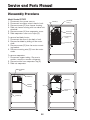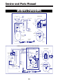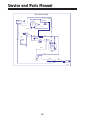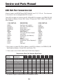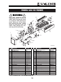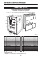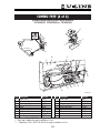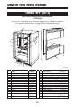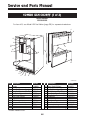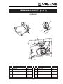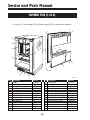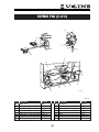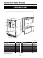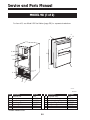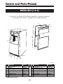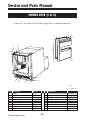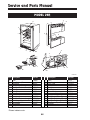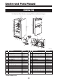
1
SERVICE AND PARTS
MANUAL
For Product Manufactured With
HFC-134A Freon
Models
95 Icemaker
98 Icemaker
BI15 Icemaker
15R
15 Wine Captain
Combo 75 Frost Free
Combo 75A
75AD
75 Wine Captain
75 Freezer
75R
75RF
Combo 29 Frost Free
Combo 29A
29AD
29R
29 Wine Captain
SP18
U-Line Corporation
U-Line Corporation
8900 North 55th Street
Milwaukee, WI 53223
U-Line Corporation
PO Box 245040
Milwaukee, WI 53224-9540
www.U-LineService.com
Phone (414) 354-0300 • FAX (414) 354-7905
Service & Parts Tech Lines Phone (800) 779-2547 • FAX (414) 354-5696
R
R
C
R
Service and Parts Manual
INTRODUCTION
Three generations of pride and quality manufacturing and design improvements are built
into all U-Line products.
This manual contains specific instructions for servicing the entire line of U-Line Products
which includes these models:
95 Icemaker
98 Icemaker
BI15 Icemaker
15R
15 Wine Captain
Combo 75 Frost Free
Combo 75A
75AD
75R
75 Wine Captain
75 Freezer
75RF
Combo 29 Frost Free
Combo 29A
29AD
29R
29 Wine Captain
SP18
This Service Manual has been written to cover product manufactured with HFC-134a.
Units previously manufactured with CFC-12 will, however, be in service for many years.
SERVICING CFC-12 SYSTEMS
U-Line Corporation has not approved the use of any “drop in” replacements for CFC-12.
U-Line has also not approved the process of converting a CFC-12 system to any other
type of refrigerant.
POTENTIAL PROBLEMS WITH HFC-134A
HFC-134A compressors will be received with a synthetic based ester oil charge. The
hygroscopic (water attraction) property of ester oil is many times greater than that of
the mineral oils previously used with CFC-12. High system moisture causes the formation of acids and alcohol which can damage the compressor. Systems should not be left
open for more than fifteen (15) minutes at any time as humidity from the air will enter
system. To assure system dehydration, the system should be pulled down to 100
microns and vacuum pump oil (mineral oil) must not be allowed to enter then system.
Cleanliness of the system will be extremely important. The presence of residues (chlorinated or greasy residues, mineral oil, or impurities) can lead to capillary tube restrictions, oil return problems and compressor damage. Flux must not be used on brazed
joints.
2
TABLE OF CONTENTS
Introduction . . . . . . . . . . . . . . . . . . . . . . . . . . . . . . . . . . . . . . . . . . . . . . . . . . . .2
Limited Warranty . . . . . . . . . . . . . . . . . . . . . . . . . . . . . . . . . . . . . . . . . . . . . . . .5
Safety Precautions . . . . . . . . . . . . . . . . . . . . . . . . . . . . . . . . . . . . . . . . . . . . . . .6
Warranty Claims Procedure . . . . . . . . . . . . . . . . . . . . . . . . . . . . . . . . . . . . . . . . .7
Guide for Screening Customer Calls . . . . . . . . . . . . . . . . . . . . . . . . . . . . . . . . . . .8
Refrigeration Systems . . . . . . . . . . . . . . . . . . . . . .
Normal Vapor/Compression Cycle Refrigeration
U-Line Frost Free Refrigeration System . . . . . .
Compressor/Electrical Specifications . . . . . . . .
Refrigeration System Diagnosis Guide . . . . . . .
.
.
.
.
.
.
.
.
.
.
.
.
.
.
.
.
.
.
.
.
.
.
.
.
.
.
.
.
.
.
.
.
.
.
.
.
.
.
.
.
.
.
.
.
.
.
.
.
.
.
.
.
.
.
.
.
.
.
.
.
.
.
.
.
.
.
.
.
.
.
.
.
.
.
.
.
.
.
.
.
.
.
.
.
.
.
.
.
.
.
.10
.10
.11
.12
.13
Ice Maker Operation . . . . . . . . . . . . . . . . . . . . . . . . . . .
Ice Maker Operating Cycles . . . . . . . . . . . . . . . . . .
Cycle Schematics . . . . . . . . . . . . . . . . . . . . . . . . .
Freeze Cycle . . . . . . . . . . . . . . . . . . . . . . . . .
Harvest-1 Cycle (Hold switch in normal position) .
Harvest-2 Cycle (Hold switch in switched position)
Water Fill Cycle . . . . . . . . . . . . . . . . . . . . . . .
Temperature Control Specifications . . . . . . . . . . . . .
Limit Switch Specifications . . . . . . . . . . . . . . . . . . .
Ice Maker Diagnosis Flow Chart . . . . . . . . . . . . . . .
.
.
.
.
.
.
.
.
.
.
.
.
.
.
.
.
.
.
.
.
.
.
.
.
.
.
.
.
.
.
.
.
.
.
.
.
.
.
.
.
.
.
.
.
.
.
.
.
.
.
.
.
.
.
.
.
.
.
.
.
.
.
.
.
.
.
.
.
.
.
.
.
.
.
.
.
.
.
.
.
.
.
.
.
.
.
.
.
.
.
.
.
.
.
.
.
.
.
.
.
.
.
.
.
.
.
.
.
.
.
.
.
.
.
.
.
.
.
.
.
.
.
.
.
.
.
.
.
.
.
.
.
.
.
.
.
.
.
.
.
.
.
.
.
.
.
.
.
.
.
.
.
.
.
.
.
.
.
.
.
.
.
.
.
.
.
.
.
.
.
.14
.14
.15
.15
.15
.16
.16
.17
.18
.19
Frost Free Units . . . . . . . . . . . . . . . . . . . .
Redesign Differentiation . . . . . . . . . . .
Typical Frost Free Airflow Configuration
Disassembly Procedures . . . . . . . . . .
Combo 75FF . . . . . . . . . . . . . . .
Combo 29FF . . . . . . . . . . . . . . .
75RF . . . . . . . . . . . . . . . . . . . .
.
.
.
.
.
.
.
.
.
.
.
.
.
.
.
.
.
.
.
.
.
.
.
.
.
.
.
.
.
.
.
.
.
.
.
.
.
.
.
.
.
.
.
.
.
.
.
.
.
.
.
.
.
.
.
.
.
.
.
.
.
.
.
.
.
.
.
.
.
.
.
.
.
.
.
.
.
.
.
.
.
.
.
.
.
.
.
.
.
.
.
.
.
.
.
.
.
.
.
.
.
.
.
.
.
.
.
.
.
.
.
.
.
.
.
.
.
.
.
.20
.20
.21
.22
.22
.23
.24
.
.
.
.
.
.
.
.
.
.
.
.
.
.
.
.
.
.
.
.
.
.
.
.
.
.
.
.
.
.
.
.
.
.
.
.
.
.
.
.
.
.
.
.
.
.
.
.
.
.
.
.
.
.
.
.
.
.
.
.
.
.
.
.
.
.
.
.
.
.
.
.
.
.
.
.
.
.
.
.
.
.
.
.
.
Troubleshooting . . . . . . . . . . . . . . . . . . . . . . . . . . . . . . . . . . . . . . . . . . . . . . . .25
Wiring Diagrams . . . . . . . . . . . . . . . . . . . . . . . . . . . . . . . . . . . . . . . . . . . . . . .28
Parts Listing . . . . . . . . . . . . . . . . . . . . . . . . . . . . .
Model 402 Ice Maker Assembly Parts Breakdown
Parts Breakdown by Models . . . . . . . . . . . . . . .
How to Order Replacement Parts . . . . . . . . . . .
Fax Parts Order Form . . . . . . . . . . . . . . . . . . .
3
.
.
.
.
.
.
.
.
.
.
.
.
.
.
.
.
.
.
.
.
.
.
.
.
.
.
.
.
.
.
.
.
.
.
.
.
.
.
.
.
.
.
.
.
.
.
.
.
.
.
.
.
.
.
.
.
.
.
.
.
.
.
.
.
.
.
.
.
.
.
.
.
.
.
.
.
.
.
.
.
.
.
.
.
.
.
.
.
.
.
.
.
.
.
.
.
.
.
.
.
.72
.39
.40
.72
.73
Service and Parts Manual
Warranty Statement
On 11-1-98, U-Line Corporation modified the warranty provided with our units. We have
significantly improved the coverage of the sealed system in years two through five of the
unit’s life. The new warranty covers parts and labor for one year from the date of purchase. In years two through five, from the date of purchase, the warranty covers parts
and labor for the entire sealed system. The sealed system consists of the compressor,
condenser, evaporator, heat exchanger, dryer, hot gas bypass-valve and all connecting
tubing.
This decision reflects our continuing commitment to strive to maintain the leadership
position within the under counter refrigeration and ice making industry whether that be
through design, product innovation, or enhanced consumer warranties. This decision
reinforces the confidence that U-Line has in the performance and reliability of our products.
Our previous warranty covered parts and labor for one year from the date of purchase
plus four additional years for the compressor, part only.
The new, modified warranty applies only to units shipped after 11-1-98. All units
shipped before 11-1-98 have the previous warranty.
PRODUCTS SHIPPED BEFORE 11-1-98 - Warranty covers parts and labor for one year
from the date of purchase, plus four additional years for the compressor (part only).
PRODUCTS SHIPPED AFTER 11-1-98 - Warranty covers parts and labor for one year
from the date of purchase and covers parts and labor for the entire sealed system for
five years.
DETERMINING SHIP DATES
In order to assure that U-Line is Y2K compliant, we have recently completed a major
computer system modification. The new computer system has lead to changes in the
way we operate in most areas of the company. You’ll soon notice that our packing lists
are different, our invoices are different, our checks are different, and more. The change
that will impact you the most is the change in serial numbers.
With the new computer system, our serial number format has changed. There are some
definite advantages that go with the new format, such as being able to tell the month
and year in which the unit was produced.
The new serial number format breaks the number down into four segments. A typical
serial number is 99 918-06-9351. The first segment -–99, represents the year that the
unit was made. The second segment – 918, represents the shop order number. This
can be a three or four digit number. Order number 918 is assigned for Model 29 Black
–00 units made in June. The third segment – 06 represents the month that the unit was
made. The forth segment – 9351 represents a sequence of numbers that is used internally at U-Line Corporation.
4
LIMITED WARRANTY
U-Line Corporation warrants each U-Line product to be free from defects in materials
and workmanship for a period of one year from the date of purchase; and warrants the
sealed system (consisting of the compressor, the condenser, the evaporator, the hot gas
bypass valve, the dryer and the connecting tubing) in each U-Line product to be free from
defects in materials and workmanship for a period of five years from the date of purchase. During the initial one-year warranty period for all U-Line products U-Line shall: (1)
at U-Line’s option, repair any product or replace any part of a product that breaches this
warranty; and (2) for all Marine, RV and Domestic U-Line products sold and serviced in
the United States (including Alaska and Hawaii)and Canada, U-Line shall cover the labor
costs incurred in connection with the replacement of any defective part. During years
two through five of the warranty period for the sealed system, U-Line shall:. (1) repair
or replace any part of the sealed system that breaches this warranty; and (2) for all
Marine, RV and Domestic U-Line products sold and serviced in the United States (including Alaska and Hawaii)and Canada, U-Line shall cover the labor costs incurred in connection with the replacement of any defective part of the sealed system. All other charges,
including transportation charges for replacements under this warranty and labor costs
not specifically covered by this warranty, shall be borne by you. This warranty is extended only to the original purchaser of the U-Line product. The Product Registration Card
included with the product should be promptly completed by you and mailed back to
U-Line or you can register on-line at www.U-LineService.com.
The following are excluded from this limited warranty: installation charges; damages
caused by disasters or acts of God, such as fire, floods, wind and lightening; damages
incurred or resulting from shipping, improper installation, unauthorized modification, or
misuse/abuse of the product; customer education calls; food loss/spoilage; door and
water level adjustments (except during the first 90 days from the date of purchase);
defrosting the product; adjusting the controls; door reversal; or cleaning the condenser.
If a product defect is discovered during the applicable warranty period, you must promptly notify either the dealer from whom you purchased the product or U-Line at P.O. Box
23220, Milwaukee, Wisconsin 53223 or at 414-354-0300. In no event shall such
notification be received later than 30 days after the expiration of the applicable warranty
period. U-Line may require that defective parts be returned, at your expense, to U-Line’s
factory in Milwaukee, Wisconsin, for inspection. Any action by you for breach of warranty must be commenced within one year after the expiration of the applicable warranty
period.
This limited warranty is in lieu of any other warranty, express or implied, including, but
not limited to any implied warranty of merchantability or fitness for a particular purpose; provided however, that to the extent required by law, implied warranties are
included but do not extend beyond the duration of the express warranty first set forth
above. U-Line’s sole liability and your exclusive remedy under this warranty is set forth
in the initial paragraph above. U-Line shall have no liability whatsoever for any incidental, consequential or special damages arising from the sale, use or installation of the
product or from any other cause whatsoever, whether based on warranty (express or
implied) or otherwise based on contract, tort or any other theory of liability.
Some states do not allow limitations on how long an implied warranty lasts or the exclusion or limitation of incidental or consequential damages, so the above limitations may
not apply to you. This warranty gives you specific legal rights, and you may also have
other rights which vary from state to state.
5
Service and Parts Manual
SAFETY PRECAUTIONS
Do not attempt to service or repair the unit until you have read the entire procedure.
Safety items throughout this manual are labeled with Warning or Caution.
!
!
Warning means that failure to follow this safety statement may result in
extensive product damage, serious personal injury, or death.
!
Caution means that failure to follow this safety statement may result in minor
or moderate personal injury, property or equipment damage.
!
!
DANGER: Risk of child entrapment. Before you throw away an old refrigerator or freezer: Take off the doors, leave shelves in place so that children may
not easily climb inside.
!
!
• Never attempt to repair or perform maintenance on the unit until the electricity has been disconnected.
• Altering, cutting of power cord, removal of power cord, removal of power
plug, or direct wiring can cause serious injury, fire and/or loss of property
and/or life and will void the warranty.
!
• Do not lift unit by door handle.
• Never use an ice pick or other sharp instrument to help speed up defrosting. These instruments can puncture the inner lining or damage the cooling unit.
• Failure to clean the condenser every three months can cause the unit to
malfunction. This could void the warranty.
• Never install the unit behind closed doors. Be sure front grille is free of
obstruction. Obstructing free air flow can cause the unit to malfunction,
and may void the warranty.
6
WARRANTY CLAIMS PROCEDURE
When submitting claims for warranty payment, please follow these guidelines.
You can use any form you would normally use to bill your customer (your own computer
generated form, Narda, USA, etc.).
The model and serial number MUST be on the claims. Claims will not be paid without a
model and serial number.
If you work on more than one unit per service call please submit a separate claim for
each unit.
We track all defects through warranty claims, so please be specific on what the repair
was. If it is a system leak, please specify where the leak was.
Please be sure the claim is legible. If the claim form cannot be read, it will be returned,
unpaid.
U-Line will not cover part or labor claims for the replacement of a complete ice maker
assembly. All ice maker parts are available as replacement parts and are stocked in our
inventory. Remember: we do not pay customer education calls. Door and water level
adjustments are 90 day warranties only.
If you are changing out a unit please supply the model and serial number of both units
(the unit being replaced and the new unit) and the R.A. number.
Occasionally the customer does not return their warranty cards. In this case we use the
date the unit was shipped to our distributor for a beginning warranty date. This may
cause the claim to be rejected for a proof of purchase. If you want to check on a purchase date, you may contact the U-Line Corp. Customer Assurance Department at
1-800-779-2547. This will allow you to get a proof of purchase, if needed, before you
submit the claim.
At U-Line, parts and labor claims are paid separately. Included in labor would be freon
and recovery charges, all other parts are handled by the parts department. We require
that some parts be returned to us, so we may return them to our vendor. It will be
noted on your packing list if we require you to return the part. If a part is to be returned
please include a copy of the packing list and a copy of your claim. If the part was purchased at one of our part distributors, you must handle the part warranty with that company. For labor payment please send a readable copy of your claim to U-Line
Corporation, P.O. Box 245040, Milwaukee WI, 53224-9540, for warranty payment.
7
Service and Parts Manual
GUIDE FOR SCREENING CALLS
U-line’s warranty does not cover customer education calls. It has been reported that as
high as 50% of all service calls performed, are customer education calls.
The following guide has been developed to help screen calls on the most common customer education issues. It can be used by persons scheduling service calls.
CUSTOMER The unit is not cold enough!
COMPLAINT Questions to ask before scheduling a service call —
• Are you familiar with the factory specifications for this unit? (many factors can cause
these figures to vary. Ambient temperature, application, amount of use etc.)
Model Numbers
Approximate Temperatures
15WC, 29WC, 75WC
60° top rack /55° middle/ 45° bottom
15R, 29R, 75R
38°
75AD, 75, 29AD
38° fresh food, 15° freezer
C75A, C75FF, C29A, C29FF
38° fresh food
• Is the door sealing properly? If the door is not sealed properly, it allows heat into the
unit. U-Line's warranty is 90 days for door adjustments.
• Is the condenser clean? U-Line's warranty does not cover cleaning the condenser.
• Is the unit behind closed doors? The unit must have free air flow to the front grille.
• Did you try turning the temperature control colder? Turning the control knob clockwise is colder. Be sure to allow 24 hrs. between temperature control adjustments.
• For model 29AD only. Is the defrost timer set to the time of day? When set properly,
the unit will be off, defrosting, between midnight and 3:30 a.m.
• For Wine Captain Units only. Is the light on constantly to display the wine? If the
light is on constantly, this could cause the unit to run warmer.
CUSTOMER The ice cubes are sticking together!
COMPLAINT Questions to ask before scheduling a service call —
• Does the unit need to be defrosted?
• Is the door sealing properly? This could cause the ice cubes to stick together.
• Have you tried to ruffle the the ice bucket? If the ice sits without being used, it will
tend to stick together. Shaking the bucket will usually break apart the ice cubes. If
the ice has been sitting for a long time, we recommend dumping the bucket and making fresh ice.
8
CUSTOMER No ice or not enough ice!
COMPLAINT Questions to ask before scheduling a service call —
• Are you aware of the factory specifications for ice production?
Model #
Approx. Daily Ice Rate
Approx. Ice Storage
Combo 75A
22.5 lbs.
13 lbs. bucket
Combo 75FF
8 lbs.
13 lbs. bucket
Combo 29A
22 lbs.
13 lbs. bucket
Combo 29FF
8 lbs.
13 lbs. bucket
Model 95
23 lbs.
12 lbs. bucket
Model 98
25 lbs.
25 lbs. bucket
BI15
25 lbs.
25 lbs. bucket
• Is the temperature control set to the warmest setting? The unit will produce the most
ice when set at the warmest setting. Let the unit run overnight.
• Is the ice maker bin arm down? When the arm is up, it will not make ice.
• Is the door sealing properly? U-Line's warranty is 90 days for door adjustments.
• Does the water level need to be adjusted? U-Line's warranty is 90 days for water level
adjustments.
CUSTOMER The unit is frosting up!
COMPLAINT Questions to ask before scheduling a service call —
• Are you familiar with the defrost technology of the unit?
Defrost Technology
Model Numbers
Manual Defrost
Combo 75A, Combo 29A, 95, 98, 75, BI15
Cycle Defrost
75R, 29R, 15R, 75WC, 29WC, 15WC, BC85DT
Auto Defrost
29AD, 75AD (periodic manual defrost may be needed)
Frost Free
Combo 75FF, Combo 29FF
• Is the door sealing properly? U-Line's warranty is 90 days for door adjustments.
• Has the door been left open?
• Is the unit in an application of heavy usage? Heavy usage or high ambient temperatures will cause a unit to frost up.
CUSTOMER Water is leaking out of the back
COMPLAINT Questions to ask before scheduling a service call —
of the unit!
• Have you checked the connection at the water solenoid valve? U-Line's warranty does
not cover installation adjustments.
CUSTOMER The light on my Wine Captain never
COMPLAINT Questions to ask before scheduling a service call —
shuts off!
• Did you turn the on/off switch near the base of the unit? The on/off switch is for the
light operation only. When the switch is in the off position, the light will turn on only
when the door is open. When the switch is in the on position, the light will be on constantly to display the wine. To shut the unit off, turn the temperature control all the
way counterclockwise.
9
Service and Parts Manual
REFRIGERATION SYSTEMS
Normal Vapor/Compression Cycle Refrigeration
• Refrigerant is pumped from the compressor to the condenser as a high pressure,
high temperature vapor.
• As the refrigerant cools in the high pressure condenser, the vapor condenses to liquid.
During this phase change, a great amount of heat is rejected with the help of the condenser fan.
• The liquid then flows to the dryer where it is strained and filtered.
COMPRESSOR
CONDENSER
DRYER
EVAPORATOR
CAPILLARY TUBE
UL183-1
• From the dryer, the refrigerant flows through the capillary tube which meters the liquid
refrigerant to the evaporator. The pressure of the refrigerant is reduced to the evaporating or low side pressure.
• The reduction of pressure on the liquid refrigerant causes it to boil or vaporize until it
reaches saturation temperature. As the low temperature refrigerant passes through
the evaporator coil, it continues to absorb a lot of heat, causing the boiling action to
continue until the refrigerant is completely vaporized. It is during this phase change
that the most heat is absorbed (the cooling takes place) in the refrigerator.
• The refrigerant vapor leaving the evaporator travels through the suction line to the
compressor inlet. The compressor takes the low pressure vapor and compresses it,
increasing both pressure and temperature. The hot high pressure gas is pumped out
the discharge line and into the condenser. The cycle continues.
10
U-Line Frost Free Refrigeration System
Cooling Mode:
• Bypass solenoid valve closed
• Evaporator fan operating
• Refrigerant flows through capillary tube
• Normal vapor/compression cycle refrigeration
Defrost Mode:
• Bypass solenoid valve open
• Refrigerant flows through bypass system
• Vapor flows from condenser to evaporator without a phase change
COMPRESSOR
CONDENSER
DRYER
EVAPORATOR
FLOW WHEN SOLENOID
VALVE IS CLOSED
CAPILLARY TUBE
FLOW WHEN SOLENOID
VALVE IS OPEN
SOLENOID VALVE
UL183-2
11
Service and Parts Manual
Compressor/Electrical Specifications
EMI ER
OVERLOAD PROTECTOR
C
STARTING RELAY
S
R
RELAY COVER
UL183-3
Compressor Pins
To measure start winding resistance, measure across the C-S pins.
To measure run winding resistance, measure across the C-R pins. These pins should
never measure any resistance to ground. This would indicate a shorted compressor.
Specifications
EMI3OHER Start Winding Resistance:
EMI3OHER Run Winding Resistance:
28 OHMS
8 OHMS
SD39 Start Winding Resistance:
SD39 Run Winding Resistance:
11 OHMS
5 OHMS
EMI5OHER Start Winding Resistance:
EMI5OHER Run Winding Resistance:
12 OHMS
4 OHMS
SD51 Start Winding Resistance:
SD51 Run Winding Resistance:
115 VOLT Ice Maker Heater Resistance:
115 VOLT Water Valve Coil Resistance:
5 OHMS
5 OHMS
80 OHMS
335 OHMS
12
13
Slightly below
room
temperature
Normal
Higher than
normal
Lower than
normal
Somewhat
lower than
normal-in
vacuum
In deep
vacuum
0 PSIG
to
25"
Normal
Overcharge
Undercharge
Partial
Restriction
Complete
Restriction
No
Gas
Room
temperature
(cool)
Room
temperature
(cool)
Warm - near
room
temperature
Warm - near
room
temperature
Very cold
may frost
heavily
Suction
Line
Suction
Pressure
System
Condition
Cool
to
hot
Room
temperature
(cool)
Very hot
Hot
Slightly warm
to hot
Very hot
Compressor
Discharge
Room
temperature
(cool)
Room
temperature
(cool)
Top passes
warm Lower passes
cool
(near room
temperature)
due to liquid
Warm
Hot to warm
Very hot
Condenser
Room
temperature
(cool)
Room
temperature
(cool)
Room
temperature
(cool) or
colder
Warm
Cool
Warm
Capillary
Tube
Cold
Cold
Evaporator
No
refrigeration
No
refrigeration
Extremely cold
near inlet Outlet
below room
temperature
backing up
Extremely cold
near inlet Outlet
below room
temperature
Refrigeration System Diagnosis Guide
Lower than
normal
Lower than
normal
Lower than
normal
Lower than
normal
Higher than
normal
Normal
Wattage
Service and Parts Manual
ICE MAKER OPERATION
Ice Maker Operating Cycles
1.
FREEZE CYCLE
A. Temperature control terminals 2 and 3 are closed
B. Power to the compressor
C. Power to the condenser fan
2.
HARVEST-1 CYCLE
A. Temperature control terminals 2 and 3 are open - 2 and 1 close
B. No power to the compressor or condenser fan
C. If bin arm is down, power goes through bin arm switch to ice maker motor
and mold heater. If bin arm is up, the ice maker will not harvest.
3.
HARVEST-2 CYCLE
A. Ice maker ejector blades reach approximately 2:00 position and cam
depresses the hold switch. Power goes through the hold switch to the ice
maker motor and mold heater.
B. Ejector blades stall on ice and ice maker motor pulsates until mold heater
warms and ice releases.
4.
WATER FILL CYCLE
A. Ice maker ejector blades reach approximately 10:00 position and cam
depresses the water fill switch.
B. Power to the water valve. Ice maker mold fills.
5.
EJECT CYCLE
A. Ejector blades push ice into bucket and stop at 12:00 position.
B. Temperature control terminals 2 and 3 have closed during harvest cycle.
C. Next freeze cycle begins with power to the compressor and condenser fan.
14
Cycle Schematics
FREEZE CYCLE
black
ON
OFF
SWITCH
black
black
FAN
MOTOR
ground
brown
COMP.
START
RELAY
black
OVER
LOAD
WATER
VALVE
black
blue
HOLD
SWITCH
LIMIT
SWITCH
NC
WATER
C
C
NO
yellow
FILL
NC
SWITCH
2
3
ICE
MAKER
MOTOR
black
black
white
TEMP.
CONTROL
red
1
NO
C
BIN
SWITCH
orange
orange
black
black
MOLD HEATER
orange
UL183-4
HARVEST-1 CYCLE
(Hold Switch In Normal Position)
black
ON
OFF
SWITCH
black
black
FAN
MOTOR
ground
brown
black
COMP.
START
RELAY
OVER
LOAD
WATER
VALVE
black
blue
HOLD
SWITCH
LIMIT
SWITCH
NC
WATER
C
black
C
NO
yellow
FILL
NC
SWITCH
2
3
black
white
ICE
MAKER
MOTOR
TEMP.
CONTROL
red
1
NO
C
BIN
SWITCH
orange
orange
black
black
MOLD HEATER
orange
UL183-5
15
Service and Parts Manual
Cycle Schematics
HARVEST-2 CYCLE
(Hold Switch In Switched Position)
black
ON
OFF
SWITCH
black
black
FAN
MOTOR
ground
brown
COMP.
START
RELAY
black
OVER
LOAD
WATER
VALVE
black
blue
HOLD
SWITCH
LIMIT
SWITCH
NC
WATER
C
C
NO
yellow
FILL
NC
SWITCH
2
3
ICE
MAKER
MOTOR
black
black
white
TEMP.
CONTROL
red
1
C
NO
BIN
SWITCH
orange
orange
black
black
MOLD HEATER
orange
UL183-6
WATER FILL CYCLE
black
ON
OFF
SWITCH
black
black
FAN
MOTOR
ground
brown
black
COMP.
START
RELAY
OVER
LOAD
WATER
VALVE
black
blue
HOLD
SWITCH
LIMIT
SWITCH
NC
WATER
C
black
C
NO
yellow
FILL
NC
SWITCH
2
3
black
white
ICE
MAKER
MOTOR
TEMP.
CONTROL
1
C
red NO
BIN
SWITCH
orange
orange
black
black
MOLD HEATER
orange
UL183-7
16
Temperature Control Specifications
Double Throw Ice Maker Thermostat Numbers
4548, AR-19-12, 2636, 2690, 2691, 2717
These temperature controls are double throw, single pole controls. The sensing tube is
inserted into the ice maker mold and senses mold temperature. After ice is sensed in
the mold, the 2-3 contacts open (stopping the compressor) and the 2-1 contacts are
closed (starting the ice maker motor). The 2-3 contacts close (2-1 contacts open)
before the end of the ice harvest cycle. This prepares the control for the next cycle.
RED WIRE
CONNECTION
YELLOW WIRE
CONNECTION
1
2
3
ICE MAKER CONTROL
BLUE/BLACK WIRE
CONNECTION
183-8
1
2
1
2
3
3
FREEZE POSITION
ICE HARVEST POSITION
CYCLE
OPEN
CIRCUIT
CLOSED
CIRCUIT
FREEZE
2-1
2-3
HARVEST
2-3
2-1
183-9
17
Service and Parts Manual
Limit Switch Specifications
3.00
28.12
183-10
Normally Closed Bi-metal Switch
Open Temperature: 104 Degrees F
Close Temperature: 83 Degrees F
The function of this switch is to open in the event of an overheating condition. This
bi-metal thermostat is normally closed and does not initiate the ice harvest cycle.
The ice harvest cycle is initiated by a double throw, single pole switch located remotely from the ice maker assembly.
18
Ice Maker Diagnosis Flow Chart
DOES THE UNIT REFRIGERATE?
INT
ER
MIT
NO
TE
Sealed System Leak
Electrical Failure
Compressor Failure
Fan Motor Failure
Defrost System Failure
YES
NT
Low Voltage
Voltage Drop
Wiring
DOES THE UNIT HARVEST ICE
IF THE EJECTOR BLADES ARE
MOVED BY HAND OR WITH A
WRENCH ?
S
NO
YE
Temperature Control Failure
Water Adjustment
Bin Switch Failure
Y
ER
EV
Ice Motor Failure
Hold Switch Failure
Limit Switch Failure
Binding Cam/Ejector
AT 12:00
WHERE DO THE
EJECTOR BLADES
STOP?
E
AT
ER
H
3
W
:00
Mold Heater Failure
IS THERE VOLTAGE AT THE
SOLENOID VALVE TERMINALS
DURING HARVEST?
YE
S
NO
Water Switch Failure
Solenoid Valve Failure
UL183-11
19
Service and Parts Manual
FROST FREE UNITS
Redesign Differentiation
Through our continuous efforts to improve our product line, U-Line Corporation has
made some changes to the design of Models Combo 29FF and Combo 75FF.
The objective of this section is to assist the service technician in differentiating between
the previous design product and the new redesign.
The redesign involves a new compressor, evaporator and heat exchanger, condenser fan
motor, evaporator fan motor, drain trough, timer and power cord.
To address service problems which may exist in earlier designs, we developed a “Field Fix
Kit.” It involves replacing the compressor, dryer, and hot gas valve. It also includes
mounting a sheet of insulation to the back panel. Before installing the new compressor,
hot gas bypass valve, and dryer, it is imperative that the entire refrigeration system be
blown out with nitrogen to remove any excess oil. This kit is to be installed in units with
R-134a only starting with serial number 7CF300000 or 2CF300000. Installation
instructions are included in each kit ordered.
The new compressor, a Matsushita Model SD39C replaces the previous compressor, an
Embraco EMI 50 HER.
Both the previous design and the new redesign are detailed in this manual. New design
units and previous design units can be differentiated by the serial numbers. All serial
numbers for the new redesigned units start with a number higher than 600000.
(Example: 2CF600001 is a new redesigned Combo 29FF.) Previous design units have
serial numbers which start with 300001, 400001, or 500001. (Example:
7CF400001 is a previous design Combo 75FF.)
Pages 44-45 show the parts breakdown for the previous design of the Combo
29FF. The parts replaced with the kit are denoted. The wiring diagram for this
model is on page 35.
Pages 40-41 show the parts breakdown for the previous design of the Combo
75FF. The parts replaced with the kit are denoted. The wiring diagram for this
model is on page 35.
Pages 46-47 show the parts breakdown for the new, redesign of the Combo
29FF. The wiring diagram for this model is on page 36.
Pages 42-43 show the parts breakdown for the new, redesign of the Combo
75FF. The wiring diagram for this model is on page 36.
20
Typical Frost Free Airflow Configuration
Air Flow In At
Evaporator Blade
Air Passes
Through Fin/Tube
Evaporator
Air Flow Out At
Evaporator Outlet
Condensate Drains Down Trough Under Evaporator,
Into Drain Cup, And Into Condensate Pan Through
Drain Hose. The Drain Trough Is Warmed During
Defrost By Contact with Evaporator Fins.
UL183-12
21
Service and Parts Manual
Disassembly Procedures
Model Combo C075FF
1. Disconnect from power source.
2. Disconnect ice maker wires in back of unit.
3. Remove screws (6) from freezer housing.
4. Slide out freezer housing with ice maker unit
attached.
5. Remove screws (4) from evaporator cover.
6. Slide evaporator cover out of clips (2).
To remove fan blade/motor:
1. Disconnect fan wires in the back of unit.
2. Remove fan blade by sliding off fan motor
shaft.
3. Remove screws (2) from fan motor mounting bracket.
4. Remove mounting nuts (2) from fan motor
studs.
SCREWS (2)
FAN MOTOR
NUTS (2)
FAN MOTOR
AND BLADE
EVAPORATOR
CLIP (2)
EVAPORATOR
To remove evaporator:
1. Disconnect copper tubing. Be sure to
reclaim, recycle or recover refrigerant.
2. Remove screw from evaporator clip (2).
3. Slide out evaporator.
UL183-15
ICE MAKER
UNIT
SCREWS (2)
SCREWS (4)
FREEZER
HOUSING
CLIP
EVAPORATOR
COVER
SCREWS (2)
UL183-13
UL183-14
22
Model Combo C029FF
1. Disconnect from power source.
2. Disconnect ice maker wires in back of unit.
3. Remove screws (3) from freezer housing.
4. Slide out freezer housing with ice maker unit
attached.
5. Remove screws (4) from evaporator cover.
6. Slide evaporator cover out of clips (2).
To remove fan blade/motor:
1. Disconnect fan wires in the back of unit.
2. Remove fan blade by sliding off fan motor
shaft.
3. Remove screws (2) from fan motor mounting bracket.
4. Remove mounting nuts (2) from fan motor
studs.
SCREWS (2)
FAN MOTOR
NUTS (2)
FAN MOTOR
AND BLADE
EVAPORATOR
CLIP (2)
EVAPORATOR
To remove evaporator:
1. Disconnect copper tubing. Be sure to
reclaim, recycle or recover refrigerant.
2. Remove screw from evaporator clip (2).
3. Slide out evaporator.
UL183-18
ICE MAKER
UNIT
SCREWS (2)
SCREWS (4)
FREEZER
HOUSING
CLIP
EVAPORATOR
COVER
UL183-16
UL183-17
23
Service and Parts Manual
Model Combo 75RF
1. Disconnect from power source.
2. Remove freezer door.
3. Slide out mullion.
4. Remove screws.
To
1.
2.
3.
4.
EVAPORATOR COVER
remove fan blade/motor:
Disconnect fan wires in the back of unit.
Remove fan blade by sliding off motor shaft.
Remove screws (2) from mounting bracket.
Remove nuts from fan motor studs.
MULLION
To
1.
2.
3.
remove evaporator:
Recover all refrigerant.
Disconnect copper tubing.
Remove mounting screws (4) from
evaporator.
4. Slide out evaporator.
UL183-19
FAN & MOTOR
EVAPORATOR
UL183-20
24
TROUBLESHOOTING
!
!
NEVER attempt to repair or perform maintenance on the unit until the main
electrical power has been disconnected.
1. Will not eject ice (water frozen)
Cause
■ Control setting too cold
■ Control defective (1-2 contacts open)
■ Bin switch defective
■ Limit switch defective (open)
■ Ice maker assembly motor stalled
■ Broken wire in ice maker circuit
■ Water soaked cabinet insulation
■ Dirty condenser
■
■
■
■
■
■
■
■
Remedy
Adjust control warmer (counterclockwise)
Replace control
Replace bin switch
Replace limit switch
Replace motor
Repair or replace wiring
Replace foamed cabinet assembly
Clean condenser
2. Will not fill with water
Cause
■ Water supply valve closed
■ Water switch defective (open)
■ Solenoid valve defective
■ Fill tube outlet frozen
■ Broken wire in water fill circuit
■
■
■
■
■
Remedy
Open water supply valve
Replace water switch
Replace solenoid valve
Replace solenoid valve and defrost fill tube
Repair or replace wiring
3. Will not stop making ice
Cause
■ Bin switch defective (closed)
■ Bin arm binding
■
■
Remedy
Replace bin switch
Lubricate bin arm pivot points or loosen
bin arm lever screw
■
■
■
■
Remedy
Replace water switch
Replace solenoid valve
Replace motor
Replace temperature control
■
Remedy
Replace control
■
■
■
Replace hold switch
Repair or replace wiring
Replace heater
4. Water will not stop filling
Cause
■ Water switch defective (closed)
■ Solenoid valve defective
■ Stalled ice maker motor
■ Temperature control defective.
Ice maker is in continuous harvest
cycle (contacts 1-2 closed)
5. Ejector blades will not stop turning
Cause
■ Control defective (1-2 contacts will
not open)
■ Hold switch defective
■ Defective wiring
■ Short in mold heater
25
Service and Parts Manual
6. Low ice production
Cause
■ Control set too cold
■ Fan motor stalled
■ Ice cubes too large
■ Dirty condenser
■ Bypass valve stuck open
■
■
■
■
■
Remedy
Adjust control warmer (counterclockwise)
Replace fan motor
Lower water fill adjustment
Clean condenser
Replace bypass valve
7. Not freezing (compressor and fan motors
Cause
■ Little or no frost pattern on evaporator ■
■ Bypass valve stuck open
■
operating)
Remedy
Check for sealed system leak or restriction
Replace bypass valve
8. Not freezing (compressor not operating Cause
■ Relay defective
■
■ Overload defective (open)
■
■ Compressor defective
■
fans operating)
Remedy
Replace relay
Replace overload
Replace compressor
9. Not freezing (compressor and fans not
Cause
■ On-Off switch defective (open)
■ Hold switch defective (open)
■ Control defective (2-3 contacts open)
■ Broken wire in freeze circuit
■ Power cord not plugged in
■ On-Off switch in off position
■ Ejector blades not in the freeze
position (12:00)
operating)
Remedy
■ Replace On-Off switch
■ Replace hold switch
■ Replace control
■ Repair or replace wiring
■ Plug in power cord
■ Put switch in on position
■ Manually advance ejector blades to the
12:00 position (test ice maker and
limit switch)
10. Compressor overheating
Cause
■ Condenser air flow restricted
■
■ Condenser fan blade obstructed
■ Condenser fan motor stalled
■ Defective compressor
■
■
■
Remedy
Remove restriction (clean condenser
and grille)
Remove blade restriction
Replace fan motor
Replace compressor
■
■
Remedy
Adjust control warmer (counterclockwise)
Replace control
11. Compressor will not stop operating
Cause
■ Control set too cold
■ Control defective (2-3 contacts will not
open)
■ Control sensing bulb not sensing
mold temperature
■
■ Evaporator fan stalled
■
Fully insert bulb into ice maker tube,
routing bulb away from compressor
discharge tube
Remove obstruction or replace motor
12. Water leak (under unit)
Cause
■ Water supply line leaking at solenoid
valve inlet
■ Water line leaking at solenoid valve outlet
■
Remedy
Tighten or replace fitting
■
Replace water line and fitting
26
■ Water line leaking at fill tube
■
■ Defrost drain line not in drain pan
■ Crack in water line
■
■
Tighten clamp or fill tube replace fill tube
assembly
Position drain line in drain pan
Replace water line
13. Water leak (inside unit)
Cause
■ Ice maker assembly fill cup obstructed
■ Fill ice cup and fill tube out of alignment
■ Water level too high
■ Defrost drain plugged
■
■
■
■
Remedy
Remove obstruction.
Align fill tube and fill cup
Adjust water level
Ice in drain trough (refer to #16)
14. Excessive frost build-up
Cause
■ Door gasket not sealing properly
■ Door out of alignment
■ Water soaked cabinet insulation
■
■
■
■ Light stays on when door is closed
■
15. Noisy
Cause
■ Copper refrigeration tube touching cabinet ■
■ Fan blade touching shroud
■
■ Fan blade obstruction (wiring, foam
■
insulation, packaging material)
Remedy
Adjust door hinges or replace door gasket
Adjust door hinges
Replace foamed cabinet assembly
(factory repair only)
Repair or adjust light bracket
Remedy
Carefully adjust tubing
Adjust fan mounting or shroud
Remove obstruction
16. Ice build-up in drain trough or drainage problem (see page 20)
Cause
Remedy
■ Obstructed drain cup or tube
■ Clear obstruction
■ Evaporator not touching drain trough
■ Reposition evaporator to contact drain
trough along entire length
■ Kinked drain tube
■ Reroute drain tube
■ Drain trough spout and drain cup
■ Align drain trough and drain cup
not aligned
17. Unit will not defrost
Cause
■ Bypass valve bent (will not operate)
■ Bypass coil defective
■ Defrost timer defective
■ Bypass valve defective
■
■
■
■
18. Fresh food temperature too cold
Cause
■ Ice bucket not fully inserted
■ Temperature control set too cold
■
■
■ Air leak at evaporator cover
■
Remedy
Align bypass valve and coil assembly
Replace bypass valve
Replace defrost timer
Replace bypass valve
Remedy
Push ice bucket in place
Adjust control to warmer setting
(counterclockwise)
Seal cover with RTV
REPLACEMENT PARTS: Use only genuine U-Line replacement parts. The use of non
U-Line parts can reduce ice rate, cause water to overflow from ice maker mold, damage the unit, and may void the warranty.
27
Service and Parts Manual
WIRING DIAGRAMS
15WC, 29WC, 75WC, 220 VOLT WIRING DIAGRAM
COMPRESSOR
CONTROL
DOOR LAMP SWITCH
WHITE
BLACK
BLUE
BLACK
8
WHITE
OVERLOAD
BLACK
BLUE
BLUE
2
3
CAPACITOR
RELAY
GREEN
FAN
BLUE
BLUE
LAMP
MATSUSHITA
RELAY
ROCKER SWITCH
OVERLOAD
BLUE
COMPRESSOR
OVERLOAD
WHITE
GREEN GRD.
RELAY
15 & 75 ONLY
GREEN
POWER CORD
EMBRACO
ASSEMBLY
KGS
WHITE - NEUTRAL
GREEN GRD.
P/N B41885
BLACK - HOT
COMBO 29A, 95, 98, & BI15 220 VOLT WIRING DIAGRAM
YELLOW
2
3
RED
BLACK
BLACK
WHITE
WHITE
BROWN
BROWN
COMPRESSOR
RED
WHITE
NO NC
BIN
SW
C
ORANGE
BLUE
8
1
OVERLOAD
BLUE
2
NO
NC
CAM
RELAY
WATER
SW
C
GREEN
BLACK
ORANGE
WATER
SOLENOID
BLACK
RELAY
GREEN
BI95 & 98 ONLY
3 RPM
MOTOR
BLACK
BLACK
WHITE
MOLD HEATER
BLACK
BLUE
ORANGE
MATSUSHITA
CONDENSER
FAN
BLUE
CAPACITOR
NC NO
HOLD
SW
ON/OFF SWITCH
OVER
LOAD
3
C
BLUE
BLACK
BLACK
BROWN
YELLOW
TEMPERATURE
CONTROL
YELLOW
RED
BLUE
OVERLOAD
WHITE
LIMIT
SW
BLACK
RELAY
COMPRESSOR
WHITE
BLACK
ICEMAKER ASSEMBLY
GREEN
WHITE (RIBBED)
EMBRACO
KGS
BLACK
GREEN
BLACK
P/N B41884
28
COMBO 75A 220 VOLT WIRING DIAGRAM (WITH BASE MOUNTED CONTROL)
YELLOW
YELLOW
TEMPERATURE
CONTROL
BLACK
3
2
1
BLACK
WHITE
WHITE
RED
BROWN
WHITE
WHITE
BROWN
BROWN
C
LAMP
NC NO
WATER
SW
C
HOLD
SW
NO
NC
DOOR
SWITCH
BLACK
NO NC
BIN
SW
C
ORANGE
YELLOW
BLACK
BLACK
RED
BLACK
WHITE
BLACK
BLACK
RED
CAM
BLACK
WHITE
WATER
SOLENOID
BLACK
OVER
LOAD
ORANGE
3 RPM
MOTOR
BLACK
BLACK
BLUE
CONDENSER
FAN
ORANGE
ON/OFF SWITCH
MOLD HEATER
RELAY
BLACK
LIMIT
SW
BLACK
GREEN
COMPRESSOR
ICEMAKER ASSEMBLY
WHITE
BLACK
KGS
WHITE (RIBBED)
GREEN
BLACK
BLACK
P/N 41886
COMBO 75A WIRING DIAGRAM
YELLOW
TEMPERATURE
CONTROL
2
BLACK
3
1
YELLOW
RED
RED
BLACK
BLACK
WHITE
WHITE
COMPRESSOR
RED
WHITE
WHITE
BLACK
BROWN
BLACK
BLACK
BLACK
BROWN
BLACK
NO NC
WHITE
ORANGE
BIN
SW
8
OVERLOAD
C
YELLOW
BROWN
BLACK
ORANGE
LIMIT
SW
OVERLOAD
WHITE
RELAY
BLACK
ICEMAKER ASSEMBLY
WHITE
BLUE
BLACK
MOLD HEATER
COMPRESSOR
MATSUSHITA
3 RPM
MOTOR
BLACK
BLACK
RELAY
GREEN
BLACK
CAM
ORANGE
BLUE
NC
WATER
SOLENOID
OVER
LOAD
GREEN
C
WHITE
BLACK
BLUE
RELAY
NC NO
WATER
SW
BLACK
C
HOLD
SW
NO
ON/OFF SWITCH
CONDENSER
FAN
BLUE
2
CAPACITOR
LAMP
DOOR
SWITCH
BLACK
3
GREEN
EMBRACO
WHITE (RIBBED)
BLACK
GREEN
29
BLACK
P/N A41881
Service and Parts Manual
MODEL 29AD WIRING DIAGRAM WITH MALLORY DEFROST TIMER
COMPRESSOR
BLACK
WHITE
BLACK
BLUE
Control
8
OVERLOAD
BLUE
3
BLUE
2
BLUE
CAPACITOR
RELAY
3
GREEN
4 2 1
Fan
WHITE
MATSUSHITA
BLACK
BLUE
MOTOR
DEFROST
TIMER
WHITE
BLUE
RELAY
WHITE
OVERLOAD
WHITE
OVERLOAD
Compressor
RELAY
GREEN
EMBRACO
WHITE
WHITE
Molded
Junction
WHITE (NEUTRAL)
POWER CORD
ASSEMBLY
GREEN
BLACK (HOT)
P/N A41857
30
29R WIRING DIAGRAM
COMPRESSOR
WHITE
Control
BLUE
8
OVERLOAD
BLACK
3
BLUE
BLUE
2
CAPACITOR
RELAY
BLUE
GREEN
Fan
BLUE
MATSUSHITA
WHITE
WHITE
RELAY
OVERLOAD
BLUE
Compressor
OVERLOAD
WHITE
RELAY
GREEN GRD.
75 F ONLY
GREEN
EMBRACO
WHITE (NEUTRAL)
GREEN (GROUND)
P/N B41852
BLACK (HOT)
SP18, BI15, COMBO 29A, 95, 98, WIRING DIAGRAM
YELLOW
RED
BLACK
BLACK
BLACK
TEMPERATURE
CONTROL
2
YELLOW
RED
COMPRESSOR
RED
WHITE
WHITE
WHITE
3
BROWN
1
BLACK
BROWN
NO NC
BIN
SW
C
ORANGE
BLACK
8
OVERLOAD
3
BLUE
2
BLUE
BLACK
RELAY
GREEN
C
YELLOW
BLUE
CAPACITOR
BROWN
NO
HOLD
SW
CAM
NC
ON/OFF SWITCH
NC NO
WATER
SW
C
MATSUSHITA
BLACK
BLUE
BLACK
WATER
SOLENOID
RELAY
OVER
LOAD
GREEN
BLACK
3 RPM
MOTOR
BLACK
WHITE
BLACK
ORANGE
ORANGE
CONDENSER
FAN
OVERLOAD
WHITE
RELAY
MOLD HEATER
COMPRESSOR
BLACK
BLACK
LIMIT
SW
ICEMAKER ASSEMBLY
WHITE
BLACK
GREEN
EMBRACO
WHITE (RIBBED)
BLACK
GREEN
BLACK
31
P/N C41883
Service and Parts Manual
75AD WIRING DIAGRAM
BLACK
COMPRESSOR
CONDENSER
COMPRESSOR
TEMP
CONTROL
FAN
GREEN
WHITE
RELAY
BLUE
BLUE
BLACK
8
OVERLOAD
OVERLOAD
BLUE
BLUE
2
3
BLACK
CAPACITOR
WHITE
LAMP
RELAY
GREEN
WHITE
DOOR
SWITCH
BLUE
BLACK
MATSUSHITA
2 1 4
WHITE
BLACK
BLACK
WHITE
BROWN
3
BLUE
MOTOR
OVERLOAD
DEFROST
TIMER
WHITE
WHITE
RELAY
POWER CORD
ASSEMBLY
WHITE
GREEN
WHITE
(RIBBED)
BYPASS
SOLENOID
GREEN
EMBRACO
BLACK
BLACK
P/N B41870
75R WIRING DIAGRAM
COMPRESSOR
WHITE
TEMP
CONTROL
BLUE
8
BLACK
OVERLOAD
3
BLUE
2
WHITE
BLUE
CAPACITOR
RELAY
BLACK
RELAY
2
BLUE
GREEN
1
MATSUSHITA
BLUE
BLACK
LOAD
GREEN
COMPRESSOR
OVER
3
CAPACITOR NOT USED
ON S43C COMPRESSOR
CONDENSER
FAN
BLUE
OVERLOAD
DOOR
SWITCH
WHITE
RELAY
LAMP
WHITE
BLACK
GREEN
WHITE
(RIBBED)
BLACK
GREEN
EMBRACO
BLACK
P/N B41880
32
WATER TANK MODELS WIRING DIAGRAM
YELLOW
YELLOW
RED
RED
BLACK
BLACK
BLACK
TEMPERATURE
CONTROL
2
RED
COMPRESSOR
WHITE
WHITE
3
BROWN
1
BLACK
WHITE
BROWN
ORANGE
BLACK
YELLOW
BLUE
WHITE
NO NC
BIN
SW
C
1861
BROWN
C
BLACK
NO
8
OVERLOAD
3
SW
CAPACITOR
RELAY
GREEN
BLACK
RELAY
GREEN
OVERLOAD
MOTOR
WHITE
BLACK
OVER
LOAD
BLACK
3 RPM
BLACK
WATER
SOLENOID
ORANGE
ORANGE
WATER PUMP
WHITE
BLUE
MATSUSHITA
C
CONDENSER
FAN
BLACK
BLUE
BLUE
2
WATER
CAM
NC
ON/OFF SWITCH
NC NO
HOLD
SW
BLACK
RELAY
MOLD HEATER
GREEN
COMPRESSOR
BLACK
BLACK
LIMIT
SW
BLACK
EMBRACO
ICEMAKER ASSEMBLY
WHITE
WHITE (RIBBED)
GREEN
BLACK
BLACK
P/N B41349
15R WIRING DIAGRAM
COMPRESSOR
Control
BLACK
WHITE
BLACK
BLUE
WHITE
8
OVERLOAD
BLUE
3
BLUE
2
BLUE
CAPACITOR
Fan
RELAY
Door Lamp Switch
GREEN
MATSUSHITA
BLUE
Lamp
RELAY
Compressor
OVERLOAD
BLUE
GREEN GRD.
OVERLOAD
WHITE
RELAY
WHITE - NEUTRAL
POWER CORD
ASSEMBLY
GREEN
GREEN GRD.
EMBRACO
BLACK - HOT
P/N A41861
33
Service and Parts Manual
75RF WIRING DIAGRAM
BLACK
BLACK
TEMP
CONTROL
COMPRESSOR
CONDENSER
BLUE
FAN
GREEN
RELAY
WHITE
OVERLOAD
BLACK
BLACK
WHITE
LAMP
WHITE
WHITE
DOOR
SWITCH
GREEN
BLACK
BLACK
WHITE
BLACK
FAN
BLACK
EVAPORATOR
PURPLE
2
1
4
3
BLACK
BROWN
MOTOR
DEFROST
TIMER
WHITE
NEUTRAL
BYPASS
SOLENOID
GREEN
WHITE
(RIBBED)
BLACK
HOT
P/N 41926
34
COMBO 75FF (Previous Design; starting S/N 7CF300000,
7CF400000 or 7CF500000) WIRING DIAGRAM
2
BLUE
TEMPERATURE
CONTROL
3
BLACK
1
RED
RED
BLACK
BLACK
WHITE
WHITE
BLACK
8
BROWN
BROWN
BLACK
WHITE
RED
WHITE
BLACK
DOOR
SWITCH
COMPRESSOR
YELLOW
YELLOW
BLACK
BLACK
WHITE
OVERLOAD
NO NC
BIN
SW
C
ORANGE
BLUE
BLUE
2
3
CAPACITOR
RELAY
LAMP
BLUE
NO
BLACK
PURPLE
BLACK
WATER
SOLENOID
WHITE
RELAY
MOTOR
BLACK
GREEN
3
4 1 2
BLACK
OVERLOAD
3 RPM
WHITE
BLACK
BLACK
ORANGE
PURPLE
WHITE
OVER
LOAD
CAM
BLACK
BLACK
ORANGE
CONDENSER
FAN
NC
ON/OFF SWITCH
NC NO
WATER
SW
C
HOLD
SW
BLUE
MATSUSHITA
C
EVAP
FAN
BLACK
YELLOW
GREEN
BROWN
RELAY
MOLD HEATER
COMPRESSOR
LIMIT
SW
BLACK
BLACK
MOTOR
GREEN
BLACK
EMBRACO
BYPASS
SOLENOID
ICEMAKER ASSEMBLY
WHITE
WHITE (RIBBED)
GREEN
BLACK
P/N A41882
BLACK
COMBO 29FF (Previous Design; starting S/N 2CF300000,
2CF400000 or 2CF500000) WIRING DIAGRAM
YELLOW
YELLOW
BLUE
TEMPERATURE
CONTROL
2
3
1
RED
RED
BLACK
BLACK
WHITE
WHITE
BROWN
RED
COMPRESSOR
NO NC
BIN
SW
C
BROWN
BLACK
ORANGE
GREEN
YELLOW
EVAPORATOR
NO
FAN
BROWN
C
BLACK
HOLD
SW
NC
CONDENSER
WHITE
BLACK
BLACK
BLACK
NC NO
WATER
CAM SW
BLACK
C
8
OVERLOAD
BLACK
WHITE
ORANGE
WATER
SOLENOID
RELAY
3 RPM
MOTOR
RELAY
GREEN
BLACK
BLUE
BLACK
BLACK
PURPLE
WHITE
OVERLOAD
BLUE
MATSUSHITA
ORANGE
BLACK
PURPLE
BLUE
2
CAPACITOR
FAN
WHITE
3
OVERLOAD
WHITE
RELAY
MOLD HEATER
COMPRESSOR
3
4 1 2
BLACK
WHITE
BLACK
MOTOR
BYPASS
SOLENOID
LIMIT
SW
GREEN
BLACK
EMBRACO
ICEMAKER ASSEMBLY
TIMER
WHITE (RIBBED)
BLACK
35
GREEN
BLACK
P/N B41858
Service and Parts Manual
COMBO 75FF (New Design; starting S/N 7CF600000) WIRING DIAGRAM
YELLOW
YELLOW
BLACK
BLUE
2
BLACK
3
WHITE
1
WHITE
BROWN
BLACK W/
ORANGE STRIPE
BLACK
WHITE
ORANGE
YELLOW
BLUE
PURPLE
RELAY
BLACK
WATER
SOLENOID
BLACK
BLACK
3
BLACK
3 RPM
OVERLOAD
MOTOR
BLACK
GREEN
COMPRESSOR
BLACK
BLACK
BLUE
MATSUSHITA
ORANGE
BLACK
GREEN
BLACK
C
BLACK
ORANGE
PURPLE
BLUE
CAPACITOR
CAM
NC
BLACK
WHITE
OVER
LOAD
WHITE
BLACK
BROWN
NC NO
WATER
SW
HOLD
SW
NO
CONDENSER
FAN
NO NC
BIN
SW
C
C
EVAP
FAN
ON/OFF SWITCH
BLACK
BROWN
LAMP
DOOR
SWITCH
BLACK
COMPRESSOR
WHITE
BLACK
TEMPERATURE
CONTROL
RED
RED
RED
4 1 2
WHITE
RELAY
MOLD HEATER
GREEN
WHITE
BLACK
BYPASS
SOLENOID
EMBRACO
BLACK
LIMIT
SW
ICEMAKER ASSEMBLY
WHITE (RIBBED)
GREEN
BLACK
P/N 41968
BLACK
COMBO 29FF (New Design; starting S/N 2CF600000) WIRING DIAGRAM
BLUE
2
3
1
YELLOW
RED
YELLOW
RED
BLACK
BLACK
WHITE
WHITE
BROWN
BROWN
RED
COMPRESSOR
WHITE
NO NC
BLACK
BIN
SW
ORANGE
NC
CAM
NC NO
WATER
SW
PURPLE
BLACK
ORANGE
WHITE
WATER
SOLENOID
RELAY
BLACK
COMPRESSOR
3
BLACK
WHITE
BLACK
TIMER
OVERLOAD
LIMIT
SW
WHITE
RELAY
EMBRACO
BLACK
ICEMAKER ASSEMBLY
BYPASS
SOLENOID
BLACK
3 RPM
MOTOR
BLUE
BLACK
MOLD HEATER
WHITE
4 1 2
MATSUSHITA
C BLACK
ORANGE
PURPLE
WHITE
WHITE
HOLD
SW
BLACK BLACK
FAN
OVERLOAD
NO
FAN
BLACK
CAPACITOR
BLACK
GREEN
BLUE
BROWN
C
ON/OFF SWITCH
YELLOW
BLACK
BLACK
C
WHITE (RIBBED)
GREEN
BLACK
36
POWER CORD
P/N 41969
15WC, 29WC, 75WC WIRING DIAGRAM
Control
BLACK
COMPRESSOR
Door Lamp Switch
BLACK
WHITE
WHITE
BLUE
BLACK
8
BLUE
Lamp
OVERLOAD
Fan
3
BLUE
2
BLUE
CAPACITOR
RELAY
GREEN
RELAY
MATSUSHITA
Rocker Switch
OVERLOAD
Compressor
BLUE
CAPACITOR NOT USED
ON S43C COMPRESSOR
GREEN GRD.
BLUE
75 & 15 ONLY
OVERLOAD
WHITE
RELAY
WHITE - NEUTRAL
GREEN GRD.
GREEN
BLACK - HOT
POWER CORD
EMBRACO
ASSEMBLY
P/N B41860
37
Service and Parts Manual
220 Volt Part Conversion List
All parts listed in the SERVICE and PARTS MANUAL are 110/115 volt. This document
is a conversion list for the applicable 220 volt part.
These 220 volt parts are used on the 95, 98 and BI15 Ice makers, the PBCM 95/98
Tank Model Ice Makers, Combo 29A, Combo 75A plus the 75WC, 29WC, and 15WC
Wine Captains.
110V PART NO.
DESCRIPTION
220V PART NO.
5263
627973
625843-S
628123-S
402
2552A
1844
31317
5402-S
5411
5412
150
5400-S
5414
5413
Fan Motor (all models)
I.M. Motor (Ice Makers)*
Mold Heater*
Mold Heater Ass’y*
Ice Maker Ass’y*
Water Valve*
Pump (95/98 Tank Model)*
Lamp Bulb
Compressor (Ice Makers)*
Overload**
Relay**
Faceplate Ass’y*
Compressor (Wine Captains)**
Relay
Overload*
5195
628109
626069-S
618
619
2555A
1844-1
31318
5404-S
5415
5416
650
5403-S
5418
5417
* Parts used on models 95/98 Ice Makers, and BI15 Ice Makers, the PBCM 95/98
Tank Model Ice Makers, Combo 29A, and Combo 75A.
** Parts used on the 15WC, 29WC and 75WC Wine Captains.
Replacement Parts For Stainless Steel Doors
Model
75RF
Description
Hinge Plate Top
Hinge Plate Bottom
Top Hinge
11624-1-S-BLK* Bottom Hinge
42021
Handle
42019
Handle
X
41995-1
Handle
41995-3
Handle
242-1-SS
Top Hinge Right
X
245-1-SS
Bottom Hinge Right
X
Part No.
1847-1-SS
1847-2-SS
1848A-S-SS
75R
75WC CO75FF BI 15
X
X
X
X
X
X
15R
15WC
X
X
X
X
X
X
X
X
X
X
X
X
X
X
X
X
X
X
* The bottom hinge for these models is only available in black.
38
MODEL 402 ICE MAKER
!
!
20
Use only genuine U-Line
replacement parts. U-Line ice
maker parts are not the same
as standard FSP Whirlpool
parts. Using non U-Line parts
can reduce ice rate, cause
water to overflow from ice
maker mold, damage the unit,
and may void the warranty.
31
32
18
13
17
16
6
23
25
2
21
14
28
30
7
22
24
11
5
8
Description
Ice Maker Ass’y
Faceplate Ass'y
Cover
Gear
Motor
Spring
Valve Switch Plate
Switch Spacer
Cam
Insulator
Hold Switch
Limit Switch
Valve Switch
Support Housing
Bin Arm
Bin Arm Spring
Ejector
Mold Heater
Stripper
Stripper Screw
29
10
26
4
Item
1
2
3
4
5
6
7
8
9
10
11
12
13
14
15
16
17
18
19
12
27
9
3
1
15
21
402ICEMAKER
402ICEMAKER
Part No.
402
150
627000
628210*
627973*
627163*
625836*
625834*
627302*
627680*
2506*
2579
2506*
625827
2603
627526
627375
625843-S
999273
489128
Item
19
20
21
22
23
24
25
26
27
28
29
30
31
32
*Parts included in the 150 faceplate assembly.
39
Description
Mold & Heater Ass’y
Water Cup
Spring & Housing Screw
Gear Screw
Face Plate
Plate Screw
Long SW Screw
Short SW Screw
Bin SW Screw
Clamp
Arm Lever
Arm Lever Screw
Motor Screw
Bin Switch
220V Motor
220V Mold Heater
220V Mold & Heater Ass’y
220V Faceplate Ass’y
220V Ice Maker Ass’y
Part No.
628123-S
544304
488372*
488957*
627782*
41375
488361*
488362*
488360
625829
625830
627199
488622*
2506
628109
626069-S
618
650
619
Service and Parts Manual
COMBO 75FF (1 of 2)
Previous Design Starting With Serial Numbers
7CF300000, 7CF400000 or 7CF500000
For Item #10, see Model 402 Ice Maker (page 39) for separate breakdown.
7
2
8
29
7
10
1
32
16
24
25
11
20
22
31
28
4
15
3
6
17
21
18
27
26
9
14
12
13
5
23
Item Description
1
2
3
4
5
6
7
8
9
10
11
12
13
14
15
16
Handle
Door Gasket
Door Shelf Retainers (3)
Shelf Retainer Rivet (6)
Door Switch
Door Ass’y
Hinge, Top, 3 Hole
Hinge, Top, 4 Hole
Pivot Screw, Top
Dr Switch Brkt
Ice Maker Ass’y
Ice Bucket
Control
Control Knob
Switch On-Off
Lamp Bulb
Ice Bin Door
COMBO75FFa
19
Part No.
Item Description
31489-4*
31493-4*
31521-1
41824
1916
75-DOOR*
11697-ST*
11849-ST*
41785-SS*
11712
402
31501
2717
41492
2053
31317
31523-S
17
18
19
20
21
22
23
24
25
26
27
28
29
30
31
32
Glass Shelf (1)
Glass Half Shelf (1)
Grille
Glass Short Shelf (2)
Trim Strip, Front Long (2)
Trim Strip, Front Short (2)
**Timer
Fan Motor, Evaporator
Fan Blade, Evaporator
Hinge, Bottom, 3 Hole
Hinge, Bottom, 4 Hole
Pivot Screw, Bottom
Freezer Housing
Ice Bin Door Hinge
Evaporator & Heat Exchange
Light Cover
Lamp Holder
*Please indicate color.
**Replaces P/N 2595 or 2632 through installation of kit.
40
Part No.
31427-1
31435
11664*
31423-1
31443-4
31443-2
2632-1
5299-1
31656
11697-SB*
11849-SB*
41747-SS*
11537-S
31463
2631-S75
31314
31316-1
COMBO 75FF (2 of 2)
Previous Design Starting With Serial Numbers
7CF300000, 7CF400000 or 7CF500000
17
C
S
M
3
RUNNING CAPACITOR
1
25
2
PTC RELAY
19
11
26
13
10
16
8
24
12
21
7
18
COMBO75FFb
Item Description
1
2
3
7
8
10
11
12
13
Water Line
Water Line Connection
Plastic Nut & Sleeve Ass’y
Cabinet Foot (4)
Dryer
Fan Motor, Condenser
Fan Blade, Condenser
Condenser
Back Panel
Part No.
Item Description
404FF
41826
41254
41319
2692
5263
5188
1951-FFS
11769
16
17
18
19
21
24
25
26
Power Cord
Solenoid Valve
*Compressor
***Relay/Overload
Bypass Valve Ass’y
Drain Pan
**Capacitor
**Insulation
* Replaces P/N 5402-FFS through installation of kit.
** New part added through installation of kit.
*** Replaces P/N's 5413 & 5414 through installation of kit.
41
Part No.
2242
2552A
5405-FFS
5421
2749-S
31550-1-F
5422
31612
Service and Parts Manual
COMBO 75FF (1 of 2)
New Design Starting With Serial Numbers
7CF600000
For Item #10, see Model 402 Ice Maker (page 39) for separate breakdown.
For Stainless Steel Models, see page 38 for handles and hinges.
7
2
8
29
7
32
10
1
16
24
25
11
20
22
15
31
28
3
4
6
17
21
18
27
26
9
14
12
13
5
23
Item Description
1
2
3
4
5
6
7
8
9
10
11
12
13
14
15
16
Handle
Door Gasket
Door Shelf Retainers (3)
Shelf Retainer Rivet (6)
Door Switch
Door Ass’y
Hinge, Top
Pivot Screw, Top
Dr Switch Brkt
Ice Maker Ass’y
Ice Bucket
Control
Control Knob
Switch On-Off
Lamp Bulb
Ice Bin Door
19
COMBO75FFc
`Item Description
Part No.
31489-4*
31493-4*
31521-1
41824
1916
75-DOOR*
11849-ST*
41785-SS*
11712
402
31501
2717
41492
2053
31317
31523-S
17
18
19
20
21
22
23
24
25
26
27
28
29
30
31
32
*Please indicate color
42
Glass Shelf (1)
Glass Half Shelf (1)
Grille
Glass Short Shelf (2)
Trim Strip, Front Long (2)
Trim Strip, Front Short (2)
Timer
Fan Motor, Evaporator
Fan Blade, Evaporator
Hinge, Bottom
Pivot Screw, Bottom
Freezer Housing
Ice Bin Door Hinge
Evaporator & Heat Exchanger
Light Cover
Lamp Holder
Part No.
31427-1
31435
11664*
31423-1
31443-4
31443-2
2632-2-S
5299-1
31656
11849-SB*
41747-SS*
11537-S
31463
2669-FFS
31314
31316-1
75FF (2 of 2)
New Design Starting With Serial Numbers
7CF600000
11
C
S
M
3
RUNNING CAPACITOR
1
17
2
PTC RELAY 13
6
7
18
9
10
5
16
8
14
4
12
COMBO75FFd
Item Description
1
2
3
4
5
6
7
8
9
Water Line
Water Line Connection
Plastic Nut & Sleeve Ass’y
Cabinet Foot (4)
Dryer
Fan Motor, Condenser
Fan Blade, Condenser
Condenser
Back Panel
Part No.
Item Description
404FF
41826
41254
41319
2692
5300
5428
1951-FFS
11769
10
11
12
13
14
16
17
18
43
Power Cord
Solenoid Valve
Compressor
Relay/Overload
Bypass Valve Ass’y
Drain Pan
Capacitor
Insulation
Part No.
2318
2552A
5405-FFS
5421
2749-S
31550-1-F
5422
31612
Service and Parts Manual
COMBO ULN-CO29FF (1 of 2)
Serial Numbers
2CF300000, 2CF400000 or 2CF500000
For Item #9, see Model 402 Ice Maker (page 39) for separate breakdown.
6
20
17
14
1
9
27
23
5
10
18
11
25
4
3
15
19
2
24
7
21
12
26
16
13
COMBO29FFa
Item Description
1
2
3
4
5
6
7
9
10
11
12
13
14
Handle
Door Gasket
Door Shelf Retainer (Long)
Door Shelf Retainer (Short)
Fan Blade, Evaporator
Pivot Hinge, Top
Pivot Hinge, Bottom
Ice Maker Ass’y
Ice Bucket
Complete Door Ass’y
Control
Grille
Ice Bin Door
Part No.
Item Description
31489-3*
31493-3*
31521-2
31521-3
31656
11697-ST*
11695-S*
402
31501
29-DOOR*
2636
11663*
31523-S
15
16
17
18
19
20
21
22
23
24
25
26
27
Glass Shelf (2) Short
Switch On-Off
Ice Bin Door Hinge (2)
Shelf Retainer Rivet (6)
Trim Strip, Front Short (2)
Pivot Screw, Top
Condenser
**Timer
Fan Motor, Evaporator
Pivot Screw, Bottom
Freezer Housing
Control Knob
Evaporator & Heat Exchanger
*Please indicate color.
**Replaces P/N 2595 or 2632 through installation of kit.
44
Part No.
31425-1
2053
31463
41824
31443-1
41785-SS*
1893-FFS
2632-1
5299-1
41747-SS*
11471-S
41492
2631-S29
COMBO ULN-CO29FF (2 of 2)
Serial Numbers
2CF300000, 2CF400000 or 2CF500000
20
C
S
M
RUNNING CAPACITOR
3
29
1
2
PTC RELAY
22
30
16
24
18
15
25
28
13
12
19
COMBO29FFb
Item Description
1
2
3
12
13
15
16
18
Water Line
Water Line Connection
Plastic Nut & Ass’y
Cabinet Foot (4)
Dryer
Fan Motor, Condenser
Fan Blade, Condenser
Back Panel
Part No.
Item Description
404FF
41826
41254
41125
2692
5263
5188
11545-1
19
20
22
24
25
28
29
30
Power Cord
Solenoid Valve
** Relay/Overload
* Compressor
By-Pass Valve Ass'y
Drain Pan
**Capacitor
**Insulation
* Replaces P/N 5402-FFs through installation of kit.
** New part added through installation of kit.
*** Replaces P/N's 5413 and 5414 through installation of kit.
45
Part No.
2317
2552A
5421
5405-FFS
2749-S
31550-1-F
5422
31622
Service and Parts Manual
COMBO ULN-CO29FF (1 of 2)
Serial Number
2CF600000
For Item #9, see Model 402 Ice Maker (page 39) for separate breakdown.
6
21
18
15
1
9
5 24
28
19
3
16
10
12
26
4
20
2
25
7
22
13
27
17
23
14
COMBO29FFc
Item Description
1
2
3
4
5
6
7
9
10
12
13
14
15
Handle
Door Gasket
Door Shelf Retainer (Long)
Door Shelf Retainer (Short)
Fan Blade, Evaporator
Pivot Hinge, Top
Pivot Hinge, Bottom
Ice Maker Ass’y
Ice Bucket
Complete Door Ass’y
Control
Grille
Ice Bin Door
Part No.
Item Description
31489-3*
31493-3*
31521-2
31521-3
31656
11697-ST*
11695-S*
402
31501
29-DOOR*
2636
11663*
31523-S
16
17
18
19
20
21
22
23
24
25
26
27
28
*Please indicate color.
46
Glass Shelf (2) Short
Switch On-Off
Ice Bin Door Hinge (2)
Shelf Retainer Rivet (6)
Trim Strip, Front Short (2)
Pivot Screw, Top
Condenser
Timer
Fan Motor, Evaporator
Pivot Screw, Bottom
Freezer Housing
Control Knob
Evaporator & Heat Exchanger
Part No.
31425-1
2053
31463
41824
31443-1
41785-SS*
1893-FFS
2632-2-S
5299-1
41747-SS*
11471-S
41492
2669-FFS
COMBO ULN-CO29FF (2 of 2)
Serial Number
2CF600000
20
C
S
M
RUNNING CAPACITOR
3
29
1
24
PTC RELAY
2
22
30
16
24
18
15
13
28
25
12
19
COMBO29FFd
Item Description
1
2
3
12
13
15
16
18
Water Line
Water Line Connection
Plastic Nut & Sleeve Ass’y
Cabinet Foot (4)
Dryer
Fan Motor, Condenser
Fan Blade, Condenser
Back Panel
Part No.
Item Description
404FF
41826
41254
41125
2692
5300
5428
11545-1
19
20
22
24
25
28
29
30
47
Power Cord
Solenoid Valve
Relay
Compressor
By-Pass Valve Ass'y
Drain Pan
Capacitor
Insulation
Part No.
2317
2552A
5421
5405-FFS
2749-S
31550-1-F
5422
31622
Service and Parts Manual
COMBO 75A (1 of 2)
For Item #10, see Model 402 Ice Maker (page 39) for separate breakdown.
7
2
8
26
1
15
10
21
17
23
21
16
11
27
23
3
6
4
18
22
19
25
24
9
12
13
14
5
20
COMBO75Aa
COMBO75Aa
Item Description
1
2
3
4
5
6
7
8
9
10
11
12
13
14
Handle
Door Gasket
Door Shelf Retainers (3)
Shelf Retainer Rivet (6)
Door Switch
Door Ass’y
Hinge, Top, 3 Hole
Hinge, Top, 4 Hole
Pivot Screw, Top
Dr Switch Brkt
Ice Maker Ass’y
Ice Bucket
Control
Control Knob
Switch On-Off
Part No.
Item Description
31489-4*
31493-4*
31521-1
41824
1916
75-DOOR*
11697-ST*
11849-ST*
41785-SS*
11712
402
31501
2690
41492
2053
15
16
17
18
19
20
21
22
23
24
Lamp Holder
Lamp Bulb
Ice Bin Door
Glass Shelf (1)
Glass Half Shelf
Grille
Glass Short Shelf (2)
Trim Strip, Front Long (2)
Trim Strip, Front Short (2)
Hinge, Bottom, 3 Hole
Hinge, Bottom, 4 Hole
25 Pivot Screw, Bottom
26 Ice Bin Door Hinge
27 Light Cover
*Please indicate color.
48
Part No.
31316-1
31317
31523-S
31427-1
31435
11664*
31423-1
31443-4
31443-2
11697-SB*
11849-SB*
41747-SS*
31463
31314
COMBO 75A (2 of 2)
12
15
2
3
1
14
8
10
7
11
5
9
4
13
6
COMBO75Ab
COMBO75Ab
Item Description
1
2
3
4
5
6
7
8
Water Line
Water Line Connection
Plastic Nut & Sleeve Ass’y
Cabinet Feet (4)
Dryer
Evaporator & Heat Exchanger
Fan Motor
Fan Blade
Part No.
Item Description
404
41826
41254
41319
2694
2189-75
5263
5188
9
10
11
12
13
14
15
*Please indicate color.
49
Condenser
Back Panel
Power Cord
Solenoid Valve
Compressor
Relay
Overload
Part No.
1951-S
11769
1855-1
2552A
5402-S
5414
5413
Service and Parts Manual
COMBO 29A (1 of 2)
For Item #8, see Model 402 Ice Maker (page 39) for separate breakdown.
5
19
16
1
13
17
14
9
4
3
10
2
18
21
6
20
22
11
15
12
COMBO29Aa
COMBO29Aa
Item Description
1
2
3
4
5
6
8
9
10
11
12
Handle
Door Gasket
Door Shelf Retainer (Long)
Door Shelf Retainer (Short)
Pivot Hinge, Top
Pivot Hinge, Bottom
Ice Maker Ass’y
Ice Bucket
Complete Door Ass’y
Control
Grille
Part No.
Item Description
31489-3*
31493-3*
31521-2
31521-3
11697-ST*
11695-S*
402
31501
29-DOOR*
AR-19-12
11663*
13
14
15
16
17
18
19
20
21
22
*Please indicate color.
50
Ice Bin Door
Glass Shelf (2) Short
Switch On-Off
Ice Bin Door Hinge (2)
Shelf Retainer Rivet (6)
Shelf Trim Strip Front (Short)
Pivot Screw, Top
Condenser
Pivot Screw, Bottom
Control Knob
Part No.
31523-S
31425-1
2053
31463
41824
31443-1
41785-SS*
1893-S
41747*
41492
COMBO 29A (2 of 2)
11
2
3
1
DETAIL "A"
9
13
8
14
7
12
6
5
4
SEE DETAIL "A"
10
COMBO29Ab
COMBO29Ab
Item Description
1
2
3
4
5
6
7
Water Line
Water Line Connection
Plastic Nut & Sleeve Ass’y
Cabinet Foot (4)
Dryer
Evaporator & Heat Exchanger
Fan Motor
Part No.
Item Description
404
41826
41254
41125
2694
2189-29
5263
8
9
10
11
12
13
14
51
Fan Blade
Back Panel
Power Cord
Solenoid Valve
Relay
Compressor
Overload
Part No.
5188
11545-1
1855-1
2552A
5414
5402-S
5413
Service and Parts Manual
MODEL 95 (1 of 2)
For Item #9, see Model 402 Ice Maker (page 39) for separate breakdown.
4
2
13
9
12
11
10
3
14
5
8
1
15
7
MODEL95a
MODEL95a
Item Description
1
2
3
4
5
7
8
Switch - On/Off
Handle
Door Gasket
Pivot Hinge, Top
Pivot Hinge, Bottom
Grille
Condenser Ass’y
Part No.
Item Description
2053
31489-1*
31493-1*
11697-ST*
11695-S*
11662*
2628-S
9
10
11
12
13
14
15
*Please indicate color.
52
Ice Maker Ass’y
Ice Bucket
Inner Liner Ass’y/Evaporator
Complete Door Ass’y
Pivot Screw, Top
Pivot Screw, Bottom
Control
Part No.
402
31429
2182-S*
95-DOOR*
41785*
41747*
2783
MODEL 95 (2 of 2)
2
3
1
16
C
13
S
M
15
5 RUNNING CAPACITOR
10-11
4
PTC RELAY
17
14
9
8
MODEL95b
MODEL95b
Item Description
1
2
3
4
5
8
9
Water Line
Water Line Connection
Plastic Nut & Sleeve Ass’y
Compressor
Capacitor
Cabinet Feet (4)
Dryer
Part No.
Item Description
404
405
41254
5401-S
5420
41125
2694
10
11
13
14
15
16
17
53
Fan Motor
Fan Blade
Back Panel-Formed
Power Cord
Insulator Tube Armaflex
Solenoid Valve
Relay
Part No.
5263
5188
11444
1855-1
31154
2552A
5419
Service and Parts Manual
MODEL 98 (1 of 2)
For Item #9, see Model 402 Ice Maker (page 39) for separate breakdown.
4
2
13
9
12
11
10
3
14
5
8
1
15
7
MODEL98a
MODEL98a
Item Description
1
2
3
4
5
7
8
Switch-On/Off
Handle
Door Gasket
Pivot Hinge, Top
Pivot Hinge, Bottom
Grille
Condenser Ass’y
Part No.
Item Description
2053
31489-2*
31493-2*
11697-ST*
11695-S*
11661*
2628-S
9
10
11
12
13
14
15
*Please indicate color.
54
Ice Maker Ass’y
Ice Bucket
Inner Liner Ass’y/Evaporator
Complete Door Ass’y
Pivot Screw, Top
Pivot Screw, Bottom
Control
Part No.
402
31430
2183-S*
98-DOOR*
41785*
41747*
2783
MODEL 98 (2 of 2)
2
3
10
1
C
S
5
M
RUNNING CAPACITOR
4
11
8, 9
7
PTC RELAY 13
6
12
MODEL98b
MODEL98b
Item Description
1
2
3
4
5
6
7
Water Line
Water Line Connection
Plastic Nut & Sleeve Ass’y
Compressor
Capacitor
Cabinet Feet (4)
Dryer
Part No.
Item Description
404
405
41254
5401-S
5420
41125
2694
8
9
10
11
12
13
55
Fan Motor
Fan Blade
Solenoid Valve
Back Panel-Formed
Power Cord
Relay
Part No.
5263
5188
2552A
11443
1855-1
5419
Service and Parts Manual
MODEL BI15 (1 of 2)
For Item #9, see Model 402 Ice Maker (page 39) for separate breakdown.
For Stainless Steel Models, see page 38 for handles and hinges.
2
4
13
9
15
12
10
3
7
14
17
16
1
8
5
MODELBI15a
Item Description
1
2
3
4
5
7
8
9
Switch- On/Off
Handle
Door Gasket, Lower
Pivot Hinge, Top
Pivot Hinge, Bottom
Grille
Condenser Ass’y
Ice Maker Ass’y
Part No.
Item Description
2053
31489-2*
31606*
11697-ST*
11695-S*
31543*
2223-S
402
10
12
13
14
15
16
17
*Please indicate color.
56
Ice Bucket
Complete Door Ass’y
Pivot Screw, Top
Pivot Screw, Bottom
Gasket, Upper
Control
Control Knob
Part No.
31430
BI15-DOOR*
41785-SS*
41747-SS*
31604*
2691
41492
MODEL BI15 (2 of 2)
10
2
3
1
4
5
11
8, 9
7
6
13
12
MODELBI15b
MODELBI15b
Item Description
1
2
3
4
5
6
7
Water Line
Water Line Connection
Plastic Nut & Sleeve Ass’y
Compressor
Overload
Cabinet Feet (4)
Dryer
Part No.
Item Description
404
41826
41254
5402-S
5413
41319
2694
8
9
10
11
12
13
57
Fan Motor
Fan Blade
Solenoid Valve
Back Panel-Formed
Power Cord
Relay
Part No.
5263
5188
2552A
41802
1855-1
5414
Service and Parts Manual
MODEL SP18 (1 of 2)
For Item #8, see Model 402 Ice Maker (page 39) for separate breakdown.
2
12
8
16
15
4
9
11
10
3
13
5
6
17
14
7
MODELSP18a
MODELSP18a
Item Description
2
3
4
5
6
7
8
9
10
Handle
Door Gasket
Pivot Hinge, Top
Pivot Hinge, Bottom
Grille
Condenser Ass'y
Ice Maker Ass'y
Ice Bucket
Inner Liner Ass’y/Evaporator
*Please indicate color.
Part No.
Item Description
11 Complete Door Ass'y, White
Complete Door Ass'y, Black
12 Pivot Screw, Top
13 Pivot Screw, Bottom
14 On-Off Switch
15 Travel Pin Ass'y
16 Travel Pin (Pin Only)
17 Frame
11777
31493-1*
11698-SS*
11696-SS*
11870
2258-S
402
31429
2182-S18
58
WHT95M-DR
95-DOORBG
41747-SSS
41747-SSS
2053
TP91-GRY-1
31476-SS
11810-KIT
MODEL SP18 (2 of 2)
13
11
12
10
2
4
3
1
9
14
8
15
5
7
6
MODELSP18b
Item Description
1
2
3
4
5
6
7
8
Water Line
Water Line Connection
Plastic Nut & Sleeve Ass'y
Compressor
Overload
Relay
Cabinet Feet
Dryer
Part No.
Item Description
404
41826
41254
5402-S
5413
5414
41125
2694
9
10
11
12
13
14
15
59
Fan Motor
Fan Blade
Back Panel
Power Cord
Solenoid Valve
Cold Control
Base
Part No.
5263
5188
11811
2264
2552A
2783
2262
Service and Parts Manual
MODEL 75RF
For Stainless Steel Models, see page 38 for handles and hinges.
13
25
41
13
40
9
16
21
22
11
3
39
8
20
17
34
35
19
1
15
4
6
5
28 4
2
36
31
10
23
24
32
14
30
29
33
38
26 37
27 18
MODEL75RF
14
Item Description
1
2
3
4
5
6
8
9
10
11
13
14
15
16
17
18
19
20
21
Dr Switch Brkt
Grille
Glass Shelves (2)
Condenser
Door Switch
Control
Lamp Bulb
Freezer Door Ass’y
Hinge, Bottom, 3 Hole
Hinge, Bottom, 4 Hole
Mullion
Hinge, Top, 3 Hole
Hinge, Top, 4 Hole
Overload
Door Gasket
Door Handle
Door Shelf Retainers (3)
Solenoid Valve Ass’y
Glass Half Shelf (1)
Door Ass’y
Evaporator Fan
Part No.
Item Description
11712
11664*
31427-1
1951-FFS
1916
2302-S
31317
31628
11697-SB*
11849-SB*
31602
11697-ST*
11849-ST*
5411
31493-4*
31489-4*
31521-1
2749-S
31435
75-DOOR*
5299-1
22
23
24
25
26
27
28
29
30
31
32
33
34
35
36
37
38
39
40
41
*Please indicate color.
60
Evaporator Fan Blade
Back Panel
Timer
Pivot Screw, Top
Dryer
Fan Motor, Condenser
Fan Blade, Condenser
Compressor
Power Cord
Evaporator & Heat Exchanger
Insulator Tube
Leveler Feet (4)
Shelf Retainer Rivets (6)
Trim Strip
Pivot Screw, Bottom
Drain Pan
Relay
Light Cover
Lamp Holder
Freezer Door Bushings
Part No.
31656
11769
2595
41785*
2692
5300
5428
5400-FFS
2263
2695-FFS
31410
41319
41824
31443-4
41747*
31550-1-F
5412
31314
31316-1
41346-4
MODEL 75WC
For Stainless Steel Models, see page 38 for handles and hinges.
8
21
24
13
9
3
16
18
12
19
31
15
10
4
14
1
20
7
6
5
2
27
28
23 17
26
22
29
32
25
11
30
MODEL75WC
Item Description
1
2
3
4
5
6
7
8
9
10
11
12
13
14
15
Dr Switch Brkt
Grille
Wine Shelf
Condenser
Switch
Control
Control Knob-Silver
Alternate Control Knob-Black
Lamp Bulb
Shelf Clip
Drain Cup
Drain Pan
Drain Trough
Hinge, Top RH/Bottom LH
Hinge, Top, 4 Hole
Hinge, Bottom RH/Top LH
Hinge, Bottom, 4 Hole
Door Gasket
Part No.
Item Description
11712
11664*
2300
1951-S
1916
2767-S
41715
41492
31317
31648
11508
31550-1-F
31391-1
242*
242-1*
245*
245-1*
31493-4*
16
17
18
19
20
21
22
23
24
25
26
27
28
29
30
31
32
*Please indicate color.
61
Door Handle
Compressor
Glass Half Shelf (1)
Door Ass’y
Light On-Off Switch
Lamp Holder
Overload
Back Panel
Light Cover
Dryer
Fan Motor
Fan Blade
Power Cord
Evaporator & Heat Exchanger
Leveler Feet (4)
Lock Ass’y
Relay
Part No.
41984-3*
5400-S
31435
75WC-DOOR*
2053
31316-1
5411
11769
31314
2694
5263
5188
2315
2186-S
41319
41734-S
5412
Service and Parts Manual
MODEL 75F
9
8
10
25
11
3
15
14
24
12
7
26
17
4
5
6
18
2
13
4
20 21
22
16
27
19
23
MODEL75F
Item Description
2
3
4
5
6
7
8
9
10
11
12
13
14
Grille
Glass Shelves (2)
Condenser
Control
Control Knob-Silver
Glass Half Shelf (1)
Pivot Screw, Top
Hinge, Top
Hinge, Top, 4 Hole
Door Gasket
Door Handle
Door Shelf Retainers (3)
Compressor
Shelf Retainer Rivet (6)
Part No.
Item Description
11664*
31427-1
1951-S
2580
41715
31435
41785-SS*
11697-ST*
11849-ST*
31493-4*
31489-4*
31521-1
5402-S
41824
15
16
17
18
19
20
21
22
23
24
25
26
Door Ass’y
Overload
Pivot Screw, Bottom
Back Panel
Dryer
Fan Motor
Fan Blade
Power Cord
Leveler Feet (4)
Trim Strip (4)
Evaporator
Hinge, Bottom
Hinge, Bottom, 4 Hole
27 Relay
*Please indicate color.
62
Part No.
75-DOOR*
5413
41747-SS*
11769
2694
5263
5188
2234
41319
31443-4
2187-FS
11697-SB*
11849-SB*
5414
MODEL 75R
For Stainless Steel Models, see page 38 for handles and hinges.
13
14
38
25
16
3
31
12
24
9
19
20
8
25
17
37
10
34
35
1
15
4
6
28
5 2
23
22
30
36
18
26
27
11
33
MODEL75R
Item Description
1
2
3
4
5
6
8
9
10
11
12
13
14
15
16
17
18
Dr Switch Brkt
Grille
Glass Shelves (2)
Condenser
Door Switch
Control
Lamp Bulb
Glass Half Shelf (1)
Drain Cup
Drain Pan
Drain Trough
Hinge, Top, 3 Hole
Hinge, Top, 4 Hole
Pivot Screw, Top
Door Gasket
Door Handle
Door Shelf Retainers (3)
Compressor
Part No.
Item Description
11712
11664*
31427-1
1951-S
1916
2766-S
31317
31435
11508
31550-1-F
31391-1
11697-ST*
11849-ST*
41785-SS*
31493-4*
31489-4*
31521-1
5400-S
19
20
22
23
24
25
26
27
28
30
31
33
34
35
36
37
38
*Please indicate color.
63
Shelf Retainer Rivets (6)
Door Ass’y
Overload
Back Panel
Trim Strips, Front Long (3)
Trim Strips, Rear Long (2)
Dryer
Fan Motor
Fan Blade
Power Cord
Evaporator & Heat Exchanger
Leveler Feet (4)
Hinge, Bottom, 3 Hole
Hinge, Bottom, 4 Hole
Pivot Screw, Bottom
Relay
Light Cover
Light Holder
Part No.
41824
75-DOOR*
5411
11769
31443-4
31444-4
2694
5263
5188
2306
2333-S
41319
11697-SB*
11849-SB*
41747-SS*
5412
31314
31316-1
Service and Parts Manual
MODEL 75AD
13
31
25
41
13
40
9
16
8
11
3
20
17
39
34
35
19
36
4
15
6
7
5
10
1
23
28 4
2
24
32
22
30
29
33
38
26 37
27 18
MODEL75AD
Item Description
1
2
3
4
5
6
7
8
9
10
11
13
15
16
17
18
19
20
Dr Switch Brkt
Grille
Glass Shelves
Condenser
Door Switch
Control
Control Knob - Silver
Lamp Bulb
Freezer Door Ass’y
Hinge, Bottom, 3 Hole
Hinge, Bottom, 4 Hole
AD Defrost Tray
Hinge, Top, 3 Hole
Hinge, Top, 4 Hole
Door Gasket
Door Handle
Door Shelf Retainers (3)
Solenoid Valve Ass’y
Glass Half Shelf (1)
Door Ass’y
Part No.
Item Description
11712
11664*
31427-1
1951-FFS
1916
2697
41715
31317
31628
11697-SB*
11849-SB*
31411
11697-ST*
11849-ST*
31493-4*
31489-4*
31521-1
2749-S
31435
75-DOOR*
22
23
24
25
26
27
28
29
30
31
32
33
34
35
36
37
38
39
40
41
*Please indicate color.
64
Overload
Back Panel
Timer
Pivot Screw, Top
Dryer (75AD)
Fan Motor
Fan Blade
Compressor
Power Cord
Evaporator & Heat Exchanger
Insulator Tube
Leveler Feet (4)
Shelf Retainer Rivets (6)
Trim Strip
Pivot Screw, Bottom
Drain Pan
Relay
Light Cover
Light Holder
Freezer Door Bushings
Part No.
5411
11769
2632-1
41785*
2692
5263
5188
5400-FFS
2243
2188-FFS
31410
41319
41824
31443-4
41747*
31550-1-F
5412
31314
31316-1
41346-4
MODEL 29AD
14
30
27
12
24
10
28
18
26
13-15
7
11
3
19
4
5
29
6
4
8
2
16
32
22
21
26
31
24
17
20
9
25
23
MODEL29AD
Item Description
2
3
4
5
6
7
8
9
10
11
12
13
14
15
16
17
Grille
Glass Shelves (3)
Condenser
Control
Control Knob
Shelf Retainer Rivets (6)
Auto Timer
Drain Pan
Drip Tray
Door Gasket
Door Handle
Door Shelf Retainers (Long) (2)
Door Hinge, Upper
Door Shelf Retainer (Short) (1)
Compressor
Relay
Part No.
Item Description
11663*
31426-1
1893-S
2696
41715
41824
2684
31550-1-F
31360-F
31493-3*
31489-3*
31521-2
11697-ST*
31521-3
5400-S
5412
18
19
20
21
22
23
24
25
26
27
28
29
30
31
32
*Please indicate color.
65
Door Ass’y
Back Panel
Dryer
Fan Motor
Fan Blade
Power Cord
Evaporator & Heat Exchanger
Cabinet Feet (4)
Drain Tube
Evaporator Door
Shelf Trim Strip Front (Long) (3)
Hinge Support, Bottom
Pivot Screw, Top
Overload
Pivot Screw, Bottom
Part No.
29-DOOR*
11545-1
2693
5263
5188
2314
2018-S
41125
41615-1
31659-S
31443-3
11695-S*
41785*
5411
41747*
Service and Parts Manual
MODEL 29R
14
24
29
12
28
27
18
3
11
10
13 (7)
26
26
8
4
31
19
5
2
15
16
22
30
21
9
17
20
25
23
MODEL29R
Item Description
2
3
4
5
7
8
9
10
11
12
13
14
15
16
17
Grille
Glass Shelves (3)
Condenser
Control
Door Shelf Retainer (Short) (1)
Drain Cup
Drain Pan
Drain Trough
Door Gasket
Door Handle
Door Shelf Retainers (Long) (2)
Door Hinge, Upper
Door Hinge, Lower
Compressor
Relay
Part No.
Item Description
11663*
31426-1
1893-S
2766-S
31521-3
11508
31550-1-F
31391
31493-3*
31489-3*
31521-2
11697-ST*
11695-S*
5400-S
5412
17
18
19
20
21
22
23
24
25
26
27
28
29
30
31
*Please indicate color.
66
Relay
Door Ass’y
Back Panel
Dryer
Fan Motor
Fan Blade
Power Cord
Evaporator & Heat Exchanger
Cabinet Feet (4)
Shelf Retainer Rivet (6)
Shelf Trim Strip (Long) Front (3)
Shelf Trim Strip (Long) Rear (3)
Pivot Screw, Top
Overload
Pivot Screw, Bottom
Part No.
5412
29-DOOR*
11545-1
2693
5263
5188
2234
1960-S
41125
41824
31443-3
31444-3
41785*
5411
41747*
MODEL 29WC
14
13
15
29
33
25
10
11
32
8
19
6
9
16
3
1
28
4 27
2
20
31
3
17
23
34
22
7
18
21
26
24
MODEL29WC
Item Description
1
2
3
4
6
7
8
9
10
11
13
14
15
16
17
18
Dr Switch Brkt
Grille
Condenser
Control
Drain Cup
Drain Pan
Drain Trough
Door Gasket
Door Handle
Wire Wine Rack
Light Bulb
Light Socket
Door Hinge, Upper
Hinge Plate, Lower Right
Compressor
Relay
Part No.
Item Description
11712
11663*
1893-S
2767-S
11508
31550-1-F
31391
31493-3*
41984-2-BLK
2299
31317
31316-1
1848A-S*
1847-2-S*
5400-S
5412
18
19
20
21
22
23
24
25
26
27
28
29
31
32
33
34
*Please indicate color.
67
Relay
Door Ass’y
Back Panel
Dryer
Fan Motor
Fan Blade
Power Cord
Evaporator & Heat Exchanger
Cabinet Feet (4)
Light Door Switch
Light On-Off Switch
Light Cover
Lower Hinge Support
Lock Ass’y
Hinge Plate, Top Right
Overload
Part No.
5412
WC29-DOOR
11545-1
2694
5263
5188
2315
1960-S
41125
1916
2053
31314
11624-1-S*
41734-S
1847-1-S*
5411
Service and Parts Manual
MODEL 15R
For Stainless Steel Models, see page 38 for handles and hinges.
11
16
22, 23, 24
13
34
18
6
15
3
33
5
17
10
8
7
1
25
31
12
2
21
20
3
27
26
14
32
35
4
9 30
29
25
28
MODEL15R
Item Description
1
2
3
4
5
6
7
8
9
10
11
12
13
14
15
16
17
Dr Switch Brkt
Grille
Back Panel
Feet Leveler (4)
Door Shelf Retainers (3)
Glass Shelf (3)
Glass Shelf (1)
Drain Cup
Drain Pan
Drain Trough
Hinge Bracket, Top
Hinge Bracket, Bottom
Hinge Pin, Top
Hinge Pin, Bottom
Door Ass’y
Door Handle
Door Gasket
Part No.
Item Description
18
20
21
22
23
24
25
26
27
28
29
30
31
32
33
34
35
11712
31543*
41802
41319
31521-3
11771
11770
11508
31550-1-F
31391-2
11697-ST*
11695-S*
41785-SS*
41747-SS*
15R-DOOR*
31489-2*
31493-6*
*Please indicate color.
68
Shelf Retainer Rivet (6)
Control
Door Switch (Plunger)
Lamp Cover
Lamp Holder
Lamp Bulb
Compressor
Condenser
Relay
Evaporator & Heat Exchanger
Dryer
Fan Motor, Condenser
Fan Blade, Condenser
Power Cord
Glass Trim Strip, Front (4)
Glass Trim Strip, Rear (3)
Overload
Part No.
41824
2766-S
1916
31314
31316-1
31317
5400-S
2223-S
5412
2878-01-S
2694
5263
5188
2307
31443-5
31444-5
5411
MODEL 15WC
For Stainless Steel Models, see page 38 for handles and hinges.
11
16
23, 24, 25
13
18
6
15
5
3
10
17
8
7
34
14
1
32
26
2
21
12
22
3
35
20
27
33
4
28
9
31
30
26
MODEL15WC
29
Item Description
1
2
3
4
5
6
7
8
9
10
11
12
13
14
15
16
17
Dr Switch Brkt
Grille
Back Panel
Feet Leveler (4)
Wine Rack
Wine Rack Clip
Glass Half Shelf (1)
Drain Cup
Drain Pan
Drain Trough
Hinge Bracket Ass’y, Top
Hinge Bracket, Bottom
Pivot Hinge, Top
Pivot Hinge, Bottom
Door Ass’y
Door Handle
Door Gasket
Part No.
Item Description
11712
31543*
41802
41319
2301
31648
11770
11508
31550-1-F
31391-2
1848A-S*
11624-1-S*
1847-1-S*
1847-2-S*
18
20
21
22
23
24
25
26
27
28
29
30
31
32
33
34
35
15WC-DOOR*
41984-1*
31493-6
*Please indicate color.
69
Lock Ass’y
Control
Door Switch - Plunger
Lamp On-Off Switch
Lamp Cover
Lamp Holder
Lamp Bulb
Compressor
Condenser
Relay
Evaporator & Heat Exchanger
Dryer
Fan Motor, Condenser
Fan Blade, Condenser
Power Cord
Glass Trim Strip Front
Overload
Part No.
41734-S
2767-S
1916
2053
31314
31316-1
31317
5400-S
2223-S
5412
2649-S
2694
5263
5188
2315
31443-5
5411
Service and Parts Manual
TANK MODELS
3
7
8
2
5
9
4
6 WATER LINE FROM
PUMP TO SOLENOID
11 PUMP POWER CORD
TANK MODELS
Item Description
1
1
2
3
4
5
Built-In Cabinet Trim - Model 95
Built-In Cabinet Trim - Model 98
Water Tank - Plastic
Water Tank Cover - Plastic
Pump
Nut
Part No.
Item Description
11708*
11709*
1832-BLK
509-BLK
1844
41216
6
7
8
9
10
11
*Please indicate color.
70
Water Line
Tank Hanger - Model 95/98
Tank Support - Model 95/98
Rubber Seal
Caster
Tank Cord
Part No.
41223
11650
11649
31358
41590
1861
NOTES
71
Service and Parts Manual
PARTS LISTING
How to Order Replacement Parts
1. Locate the illustration(s) for the model you are servicing.
NOTE
Some models may have more than one illustration based on Serial Number
breaks.
2. Refer to the area where the desired part would be installed, locate the part and note
the item number assigned to it.
3. Locate the item number in the left column of the parts listing which is below the product illustration. Note the full description and the corresponding part number. If this is
for a warranty unit, please indicate so.
4. When ordering parts, it will be necessary to supply us with Model Number, Serial
Number, Part Number, Part Description and in some cases Color or Voltage.
5. U-Line requires the return of the parts listed below if replaced under warranty.
•
•
•
Fan motors (condenser and evaporator)
Temperature controls
Water solenoid valves
•
•
•
Ice maker motors
Bypass solenoids
Compressors (two years old or
less - lines soldered closed)
All warranty parts will be shipped at no charge as long as warranty status has been confirmed. We require that some parts be returned to us, so we may return them to our
vendor. It will be noted on your packing list if we require you to return a part or if you
may field scrap it. When returning parts please enclose a copy of your packing list and a
copy of your labor claim, showing the model and serial number.
Our warranty records may not match the customers information. In which case a proof
of purchase will be required. If you do not have the proof of purchase at the time the
order is placed the part will be sent net 15 days (COD if you don’t have an open account
with U-Line Corporation). When the proof of purchase is provided we will credit your
account (a check will be sent if the part was sent COD).
6. Parts may be ordered by FAX, phone or on-line.
FAX Number (414) 354-7905
Phone Number (414) 354-0300 or (414) 354-7885; press 3
www.U-LineService.com
To expedite parts shipments, FAX all parts orders to: (414) 354-7905. Copy the FAX
Parts Order Form, located in the back of this manual, when placing an order.
7. Effective immediately, U-Line will not pay warranty claims for the replacement of a
complete icemaker assembly. Complete icemaker assembly replacement is not necessary because all icemaker parts are available as replacement parts and are stocked
in our inventory.
REPLACEMENT PARTS: Use only genuine U-Line replacement parts. The use of non
U-Line parts can reduce ice rate, cause water to overflow from ice maker mold, damage
the unit, and may void the warranty.
220 Volt Parts
All parts listed in the SERVICE and PARTS MANUAL are 110/115 volt. Refer to the
220 Volt Part Conversion List for the applicable 220 Volt part.
72
FAX PARTS ORDER FORM
FAX # 414-354-7905
Account# ______________________________________
Ship to: ______________________________________
Bill to: ________________________________________
______________________________________________
______________________________________________
______________________________________________
______________________________________________
Attention:
Date: __________________________________________
P.O. __________________________________________
Phone#________________________________________
Fax#__________________________________________
PART#
COLOR
QTY
DESCRIPTION
MODEL
SERIAL
NUMBER
UNIT IN
WARRANTY?
SPECIAL INSTRUCTIONS:
All part shipments will be sent ground delivery.
We have air shipment available at an additional cost to you.
Next Day Air
2nd Day Air
3 Day Select
If you do not have an open account with us your order will be shipped C.O.D.
COMMENTS: ____________________________________________________________________________________
________________________________________________________________________________________________
Authorized By ________________________________________________
P.O. Box 245040
Milwaukee, WI 53224-9540
Phone 414.354.0300
FAX 414.354.7905
Printed in U.S.A. – February 2003
P/N 41921 (Rev. 2/03)