1
SINEC
CP 5430 TF with COM 5430 TF, CP 5431 FMS with COM 5431 FMS
Volume 1 of 2
1
Introduction
11
Data Transmission with Distributed
I/Os
C79000-B8976-C060/02
2
System Overview
12
Service- und Diagnostic Functions
on SINEC L2 Bus using
FMA Services
3
Fundamentals of the Modul
13
Clock Services
4
Technical Description/Installation
14
Documentation and Testing
5
Selecting the Type of
Communication
15
Utilities
6
Basics of Configuration with NCM
16
Working with the Application
Examples
7
Data Transmission Using S5-S5
Links
17
Appendix
8
Data Transmission by Direct
Access to Layer 2-Services
A
Abbreviations
9
Data Transmission with Global
I/Os
B
Index
10
Data Transmission with Cyclic
I/Os
C
Further Reading
6GK1970-5AB01-0AA1
SINEC is a trademark of Siemens
Siemens Aktiengesellschaft
C79000-G8976-C048
Release 02
Wir haben den Inhalt der Druckschrift auf Übereinstimmung mit der beschriebenen Hard- und Software geprüft. Dennoch können Abweichungen nicht
ausgeschlossen werden, so daß wir für die vollständige Übereinstimmung keine Gewähr übernehmen.
Die Angaben in der Druckschrift werden jedoch regelmäßig überprüft. Notwendige Korrekturen sind in
den nachfolgenden Auflagen enthalten. Für Verbesserungsvorschläge sind wir dankbar.
We have checked the contents of this manual for
agreement with the hardware described. Since deviations cannot be precluded entirely, we cannot guarantee full agreement. However, the data in this manual are reviewed regularly and any necessary corrections included in subsequent editions. Suggestions for improvement are welcome.
Technical data subject to change.
Nous avons vérifié la conformité du contenu du
présent manuel avec le matériel et le logiciel qui y
sont décrits. Or, des divergences n’étant pas exclues, nous ne pouvons pas nous porter garants pour la
conformité intégrale. Si l’usage du manuel devait
révéler des erreurs, nous en tiendrons compte et apporterons les corrections nécessaires dès la prochaine édition. Veuillez nous faire part de vos suggestions.
Nous nous réservons le droit de modifier les caractéristiques techniques.
Siemens Aktiengesellschaft
Technische Änderungen vorbehalten.
Weitergabe sowie Vervielfältigung dieser Unterlage,
Verwertung und Mitteilung ihres Inhalts nicht gestattet, soweit nicht ausdrücklich zugestanden. Zuwiderhandlungen verpflichten zu Schadenersatz. Alle
Rechte vorbehalten, insbesondere für den Fall der
Patenterteilung oder GM-Eintragung.
Copyright © Siemens AG 1995
All Rights Reserved
The reproduction, transmission or use of this document or its contents is not permitted without express
written authority. Offenders will be liable for damages. All rights, including rights created by patent
grant or registration of a utility or design, are reserved.
Copyright © Siemens AG 1995
All Rights Reserved
Toute communication ou reproduction de ce support
d’informations, toute exploitation ou communication
de son contenu sont interdites, sauf autorisation expresse. Tout manquement à cette règle est illicite et
expose son auteur au versement de dommages et
intérêts. Tous nos droits sont réservés, notamment
pour le cas de la délivrance d’un brevet ou celui de
l’enregistrement d’un modèle d’utilité.
Copyright © Siemens AG 1995
All Rights Reserved
Elektronikwerk Karlsruhe
Printed in the Federal Republic of Germany
SINEC
CP 5430 TF/CP 5431 FMS with COM 5430 TF/COM 5431 FMS
Description
C79000-B8976-C060/02
Note
We would point out that the contents of this product documentation shall not become a part of or modify any
prior or existing agreement, commitment or legal relationship. The Purchase Agreement contains the complete and exclusive obligations of Siemens. Any statements contained in this documentation do not create new
warranties or restrict the existing warranty.We would further point out that, for reasons of clarity, these
operating instructions cannot deal with every possible problem arising from the use of this device. Should you
require further information or if any special problems arise which are not sufficiently dealt with in the operating
instructions, please contact your local Siemens representative.
General
WARNING !
!
This device is electrically operated. In operation, certain parts of this device carry a
dangerously high voltage.
Failure to heed warnings may result in serious physical injury and/or material damage.
Only appropriately qualified personnel may operate this equipment or work in its vicinity.
Personnel must be thoroughly familiar with all warnings and maintenance measures in
accordance with these operating instructions.
Correct and safe operation of this equipment requires proper transport, storage and
assembly as well as careful operator control and maintenance.
Personnel qualification requirements
Qualified personnel as referred to in the operating instructions or in the warning notes are defined as persons
who are familiar with the installation, assembly, startup and operation of this product and who posses the
relevant qualifications for their work, e.g.:
– Training in or authorization for connecting up, grounding or labelling circuits and devices or systems in
accordance with current standards in saftey technology;
– Training in or authorization for the maintenance and use of suitable saftey equipment in accordance with
current standards in safety technology;
– First Aid qualification.
B8976060/02
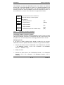
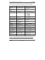
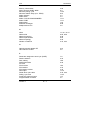
Contents
1
Introduction
1-1
2
System Overview
2-1
2.1
SINEC Overview
2-3
2.2
The PROFIBUS-Compatible Network
SINEC L2/L2FO
Standards
Network Access Technique
Transmission Techniques
Transmission According to RS-485
Transmission with Fiber Optic Cables (FO)
2
2
2
2
2
2
2.2.1
2.2.2
2.2.3
2.2.3.1
2.2.3.2
2.3
2.3.1
-
5
7
10
14
14
15
Network Topology
Topology of an Electrical SINEC L2 Network for
the RS-485 Technique
Topology of an Optical SINEC L2FO Network
Topology of a Combined Electrical / Optical
SINEC L2/L2 FO Network
2 - 21
2.4
2.4.1
2.4.2
Configuring the Network
Configuring a SINEC L2 Network for RS-485
Configuring a SINEC L2FO Network
2 - 23
2 - 23
2 - 25
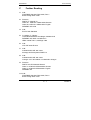
3
Fundamentals of the Model
3-1
3.1
ISO/OSI Reference Model for Communication
3-2
3.2
3.2.1
3.2.1.1
3.2.1.2
3.2.2
3.2.2.1
Architecture <-> OSI Environment
Communications Model
Relationship between Application Processes
Logical Data Exchange
Communication Relations
Addressing Model for Explicit Communication
(for S5-S5, free layer 2 and FMA)
Addressing Model for Implicit Communication
(GP, DP ZP)
3
3
3
3
3
2.3.2
2.3.3
3.2.2.2
I
2 - 18
2 - 18
2 - 20
-3
-6
-6
-7
-7
3-8
3-9
Volume 1
Contents
B8976060/02
3.3
3.3.1
3.3.1.1
3.3.1.2
3.3.1.3
3.3.2
3.3.2.1
3.3.2.2
3.3.2.3
Application Interfaces of Layer 2 Communication
Explicit Communication
S5-S5 Communication
Free Layer 2 Communication with FDL Services
Fieldbus Management with FMA Services
Implicit Communication
Global I/Os (GP)
Cyclic I/Os (ZP), only with CP 5430 TF
Distributed I/Os (DP)
3
3
3
3
3
3
3
3
3
4
Technical Description and Installation of the
CP 5430 TF/CP 5431 FMS
4-1
4.1
4.1.1
4.1.1.1
4.1.1.2
4.1.2
4.1.2.1
4.1.3
4.1.3.1
4.1.3.2
4.1.3.3
4.1.3.4
4.1.3.5
4.1.3.6
4.1.3.7
4.2
4.2.1
-
11
11
11
12
14
15
16
17
18
Technical Description
4-1
Communications Processor CP 5430 TF/CP 5431 FMS 4 - 1
Mode Indicators (RUN and STOP LEDs)
4-3
Fault LED
4-6
Data Exchange between the CPU and
CP 5430 TF/CP 5431 FMS
4-7
Hardware Monitoring (Watchdog)
4 - 11
Technical Data of the CP 5430 TF/CP 5431 FMS
4 - 12
Interfaces
4 - 12
Operating and Environmental Conditions
4 - 12
Mechanical and Electrical Data
4 - 13
Logical Characteristics
4 - 13
Performance Data CP 5430 TF
4 - 14
Performance data of the CP 5431 FMS
4 - 16
Interface Assignments
4 - 18
Memory Submodules
Memory Submodule Types for the
CP 5430 TF/CP 5431 FMS
4 - 20
4.3
4.3.1
4.3.1.1
Installation Guidelines
Basic Configuration
CP 5430 TF/CP 5431 FMS Slots in the various PLCs
4 - 21
4 - 21
4 - 21
4.4
4.4.1
Ways of Connecting PGs on the SINEC L2 Bus
Structure and Functions of the Bus Terminal
4 - 26
4 - 29
Volume 1
II
4 - 20
B8976060/02
Contents
4.4.2
Example of Transmission with RS 485 Bus Terminals
4 - 29
5
Selecting the Type of Communication
5-1
5.1
Data Transmission with HDBs (S5-S5)
5-3
5.2
Data Transmission with HDBs (Free Layer 2 Access)
5-4
5.3
Data Transmission with Global I/Os (GP)
5-5
5.4
Data Transmission with Cyclic I/Os (ZP)
(CP 5430 TF)
5-7
5.5
Data Transmission with Distributed I/Os (DP)
5-8
5.6
Communication with TF (CP 5430 TF)
5-9
5.7
Communication with FMS (CP 5431 FMS)
5 - 11
6
Basics of Configuration with NCM
6-1
6.1
6.1.1
6.1.2
6.1.3
6.1.4
SINEC NCM
The Keyboard
Menu Structure and Operation
COM Screen Layout and Operation
Special Windows
6
6
6
6
6
6.2
Installation and Start
6 - 10
6.3
General Guidelines for Working with your Software
6 - 12
6.4
Overview of Basic Configuration
6 - 14
6.5
6.5.1
6.5.2
6.5.3
6.5.3.1
Screens for Basic Configuration
Editing
CP Init
Network Parameters
Global Network Parameters
6
6
6
6
6
III
-
-
2
3
4
6
9
17
17
20
24
25
Volume 1
Contents
B8976060/02
6.5.3.2
6.5.4
6.5.4.1
6.5.4.2
6.5.4.3
6.5.4.4
6.5.4.5
6.5.4.6
Local Network Parameters
Network Functions
Network Overview
Network Matching
GP Consistency
Default S5-S5 Links
Network Documentation
Archiving
6
6
6
6
6
6
6
6
-
28
33
34
36
38
40
42
44
6.6
6.6.1
6.6.1.1
6.6.1.2
6.6.1.3
6.6.2
6.6.3
6.6.4
6.6.4.1
6.6.4.2
6.6.4.3
6.6.4.4
6.6.4.5
Transfer Functions
Start CP / Stop CP / CP Status
Start CP
Stop CP
CP Status
Delete CP
Delete FD
CP Database Transfer
FD -> CP
CP -> FD
FD -> EPROM
EPROM -> FD
FD -> FD
6
6
6
6
6
6
6
6
6
6
6
6
6
-
46
47
47
48
48
49
50
51
51
53
55
56
57
6.7
Link Configuration
6 - 59
6.8
6.8.1
6.8.2
Basic Configuration
Block Overview CP 5430 TF
Block Overview CP 5431 FMS
6 - 60
6 - 62
6 - 63
7
Data Transmission Using Configured S5-S5 Links
7-1
7.1
7.1.1
7.1.2
Basics of Data Transmission with HDBs
on Configured S5-S5 Links
Sequence of the Data Transmission
Checking with ANZW and PAFE
7-2
7-4
7-6
7.2
7.2.1
Configuring
Configuring S5-S5 Links
7 - 10
7 - 11
Volume 1
IV
B8976060/02
7.3
7.3.1
7.3.1.1
7.3.1.2
7.3.2
7.3.3
8
8.1
8.1.1
8.1.2
8.1.3
8.1.4
8.1.5
8.2
Contents
Example of a Program for an S5-S5 Link
Outline of the Task
Program for PLC 1 (S5-155 U)
Program for PLC 2 (S5-115 U)
Transferring the Configuration Data for the
CP 5430 TF/CP 5431 FMS and the STEP 5
User Program
Monitoring the Data Transmission
7 - 20
7 - 22
Data Transmission by Direct Access to
Layer 2 Services
8-1
Basics of Data Transmission using Layer 2 Services
FDL Services implemented in a
CP 5430 TF/CP 5431 FMS for Data Transmission
How Data Transmission by Direct Access to
Layer 2 Services Functions
Handling the Individual Data Transmission Services
from the Point of View of the Control Program
Checking the Data Transmission in the
Control Program using ANZW and PAFE
Sequence of the Data Transmission
7
7
7
7
-
15
17
19
20
8-2
8-3
8-9
8 - 13
8 - 13
8 - 18
Transmitting Multicast Messages by Direct
Access to Layer 2 Services
8 - 28
8.3
8.3.1
Configuring
Configuring Free Layer 2 Links
8 - 31
8 - 32
8.4
8.4.1
8.4.1.1
8.4.1.2
8.4.2
Example of a Layer 2 Link
Program Description
Program for PLC 1
Program for PLC 2
Transferring the Configuration Data for the
CP 5430 TF/CP 5431 FMS and the
STEP 5 User Program
8
8
8
8
V
-
35
36
37
37
8 - 38
Volume 1
Contents
B8976060/02
9
Data Transmission with Global I/Os
9-1
9.1
9.1.1
Basics of Data Transmission with Global I/Os
Checking the Data Transmission with
ANZW and the GP Station List
9-3
9 - 18
9.2
9.2.1
9.2.2
9.2.3
Configuring
I/O Areas CP 5430 TF
I/O Areas CP 5431 FMS
Editor for Global I/Os
9
9
9
9
-
23
24
28
32
9.3
Example of Data Transfer with Communication
using Global I/Os
Program Description
Start-up Response
Cyclic Mode
Transferring the Configuration Data for the
CP 5430 TF/CP 5431 FMS and the
STEP 5 User Program
9
9
9
9
-
35
36
42
46
9.3.1
9.3.1.1
9.3.1.2
9.3.2
9 - 47
10
Data Transmission with Cyclic I/Os (CP 5430 TF)
10 - 1
10.1
10.1.1
Basics of Data Transmission with Cyclic I/Os (ZP)
Checking the Data Transmission with
ANZW and the ZP Station List
10 - 3
10.2
10.2.1
10.2.2
Configuring
I/O Areas
ZP Editor
10 - 20
10 - 21
10 - 24
10.3
10.3.1
10.3.1.1
10.3.1.2
10.3.2
Example of using the Cyclic I/Os
Program Description
Program for PLC 1
Program for PLC 2 (S5-95U)
Transferring the Configuration Data for the
CP 5430 TF and the STEP 5 User Program
10
10
10
10
Volume 1
VI
10 - 16
-
27
28
29
29
10 - 30
B8976060/02
Contents
11
Data Transmission with Distributed I/Os
11 - 1
11.1
11.1.1
Basics of SINEC L2-DP
The SINEC L2-DP Interface for the
CP 5430 TF/CP 5431FMS
11 - 4
11.2
CP 5430 TF/CP 5431 FMS L2-DP Functions
11 - 7
11.3
Communication Between the DP Master and the
DP Slave Station
11 - 9
Basics of Data Transmission Using the
DP Service of the CP
11 - 10
11.4
11.5
11 - 6
11.5.2
11.5.3
Updating the Input and Output Areas
with the DP Service
Consistency of the Input and Output Bytes
with the DP Service of the CP
How the FREE Mode Functions
How the CYCLE-SYNCHRONIZED Mode Functions
11.6
11.6.1
11.6.2
11.6.3
11.6.4
Configuring
I/O Areas
Assigning Parameters to DP Slaves
DP Editor
Example of using the DP service
11
11
11
11
11
-
22
23
26
31
37
11.7
11.7.1
11.7.2
11.7.2.1
11.7.3
11.7.4
11.7.5
L2-DP Diagnostics with the User Program
Overview
Examples of Practical Applications
Reading out the DP station list
Reading Out the DP Diagnostic List
Request Single DP Station Diagnostic Data
Example of a Program for Requesting
Single DP Station Diagnostics
11
11
11
11
11
11
-
40
40
45
45
48
51
Sending Control Commands to the DP Slave
Function of the Control Commands Sync and Unsync
Function of the Control Commands Freeze and Unfreeze
11 - 66
11.5.1
11.8
11.8.1
11.8.2
VII
11 - 11
11 - 11
11 - 12
11 - 15
11 - 52
11 - 67
11 - 68
Volume 1
Contents
11.8.3
B8976060/02
Cyclic and Acyclic Transmission of
Global_Control Commands
Special Job "STOP DP polling list processing"
11 - 69
11 - 74
Service and Diagnostic Functions on the
SINEC L2 Bus using FMA Services
12 - 1
12.1
Use and Types of FMA Service
12 - 2
12.2
Fundamentals of using the FMA Services
12 - 5
12.3
12.3.1
12.3.2
FDL_READ_VALUE
FDL_READ_VALUE_Request
FDL_READ_VALUE_Confirmation
12 - 13
12 - 13
12 - 14
12.4
12.4.1
12.4.2
LSAP_STATUS
LSAP_STATUS_Request
LSAP_STATUS Confirmation
12 - 17
12 - 18
12 - 19
12.5
12.5.1
12.5.2
FDL_LIFE_LIST_CREATE_LOCAL
FDL_LIFE_LIST_CREATE_LOCAL Request
FDL_LIFE_LIST_CREATE_LOCAL Confirmation
12 - 22
12 - 22
12 - 23
12.6
12.6.1
12.6.2
FDL_IDENT
FDL_IDENT Request
FDL_IDENT Confirmation
12 - 25
12 - 25
12 - 26
12.7
12.7.1
12.7.2
FDL_READ_STATISTIC_CTR
FDL_READ_STATISTIC_CTR Request
FDL_READ_STATISTIC_CTR Confirmation
12 - 28
12 - 28
12 - 29
12.8
12.8.1
12.8.2
FDL_READ_LAS_STATISTIC_CTR
FDL_READ_LAS_STATISTIC_CTR Request
FDL_READ_LAS_STSTISTIC_CTR Confirmation
12 - 32
12 - 32
12 - 33
12.9
12.9.1
12.9.2
Examples
Program Example for the FDL_READ_VALUE Service
Program Example for the LSAP_STATUS Service
12 - 35
12 - 35
12 - 40
11.8.4
12
Volume 1
VIII
B8976060/02
12.9.3
12.9.4
12.9.5
12.9.6
12.9.7
Contents
Program Examples for the
FDL_LIFE_LIST_CREATE_REMOTE Service
Program Example for the
FDL_LIFE_LIST_CREATE_LOCAL Service
Program Example for the FDL_IDENT Service
Program Example for
FDL_READ_STATISTIC_CTR Service
Program Example for
FDL_READ_LAS_STATISTIC_CTR Service
12 - 42
12 - 43
12 - 45
12 - 48
12 - 51
13
Clock Services
13 - 1
13.1
Network Topology, Clock Master/Slave Functions
13 - 3
13.2
How the Clock Functions
13 - 6
13.3
Several CP 5430 TF/CP 5431 FMS Modules
on a SINEC L2 Bus
Setting and Reading the Time in the
Programmable Controller
13.3.1
13.4
13 - 8
13 - 9
Setting and Reading the Time with
COM 5430 TF/CP 5431 FMS
13 - 14
13.5
Restrictions / Tips
13 - 17
13.6
Accuracy
13 - 18
14
Documentation and Testing
14 - 1
14.1
Documentation Functions
14 - 1
14.2
14.2.1
14.2.1.1
14.2.1.2
14.2.2
14.2.2.1
Test
S5-S5/ Free L2 - Test Functions
Total Status
Single Status
GP Test Functions
Total Status of the GP Jobs
14
14
14
14
14
14
IX
-
3
4
5
10
13
13
Volume 1
Contents
B8976060/02
14.2.2.2
14.2.2.3
14.2.3
14.2.3.1
14.2.3.2
14.2.3.3
14.2.4
14.2.4.1
14.2.4.2
14.2.5
14.2.5.1
14.2.5.2
14.2.5.3
Display of the GP Output Values
Display of the GP Input Values
ZP Test Functions (CP 5430 TF)
Total Status of the ZP Jobs
Display of the ZP Output Values
Display of the ZP Input Values
DP Test Functions
DP Total Status
DP Single Status
FMA Test Functions
Local Life List
Station-oriented Statistics
Bus-oriented Statistics
14
14
14
14
14
14
14
14
14
14
14
14
14
15
Utilities
15 - 1
15.1
15.1.1
15.1.2
15.1.3
PG Functions on the SINEC L2 Bus
Bus Selection - Creating Paths in Path Files
Editing a Path
Activating the Edited Path
15
15
15
15
15.2
Change Submodule Size
15 - 10
15.3
Convert CP 5430 Database old - new (CP 5430 TF)
15 - 12
16
Working with the Application Examples
16 - 1
17
Appendix
17 - 1
17.1
Job Numbers for the CP 5430 TF
17 - 1
17.2
Job Numbers for the CP 5431 FMS
17 - 3
17.3
SAP - Job Number Assignment
17 - 5
17.4
Overview of the Error Messages
17 - 6
Volume 1
X
-
-
15
18
21
21
24
27
29
29
32
35
35
36
37
2
5
6
8
B8976060/02
17.4.1
Contents
17.4.2
17.4.3
17.4.4
Messages in the status word for predefined
S5S5 links, free layer 2 and FMA
Global I/Os - Error Bits
Cyclic I/Os Error Messages
DP Error Displays
17
17
17
17
17.5
Overview of the FMA Services
17 - 21
17.6
17.6.1
Calculation of the Target Rotation Time (TTR)
Overview
17 - 24
17 - 24
17.7
Calculating the Switch-off and Reaction Times
of the Global I/Os
17 - 30
A
Abbreviations
A-1
C
Index
B-1
C
Further Reading
C-1
XI
-
6
10
14
17
Volume 1
Contents
Volume 1
B8976060/02
XII
B8976060/02
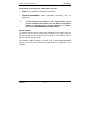
1
Introduction
Introduction
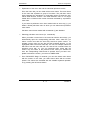
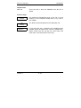
The manual for the CP 5430 TF and CP 5431 FMS is divided into two
volumes. This volume, Volume 1 of the manual describes the PROFIBUS
(PROcess FIeld BUS) communication available with the two CPs.
Differences in communication and performance are pointed out in the
appropriate chapters. The communications processors are configured with
COM 5430 TF/COM 5431 FMS under SINEC-NCM.
PROFIBUS is a bus system for applications in automation engineering in
areas closely associated with the process and allows easy implementation
of bus interfaces. With the PROFIBUS, SIMATIC S5 programmable
controllers, programmers, AT-compatible PCs and other control systems
and, of course, PROFIBUS-compatible devices from various manufacturers
can be networked.
The CP 5430 TF is used to connect SIMATIC S5 programmable controllers
to the SINEC L2/L2FO local area network and complies with the
PROFIBUS standard (DIN 19245) Part 1 /1/. The range of performance
described in Volume 2 extends the functions of the CP by the services
described in the TF standard for SINEC TF. The CP 5430 TF also provides
the L2-DP (distributed I/Os) service.
The CP 5431 FMS communications processor is used to connect
programmable controllers of the SIMATIC S5 range to the local area
network SINEC L2/L2FO and complies with the PROFIBUS standard (DIN
19245) both in Part 1 and Part 2 /10/ as an active station on the bus
(PROFIBUS multivendor network). The CP 5431 FMS also provides the
L2-DP (distributed I/Os) service.
SINEC L2-DP is the Siemens implementation of DIN E19245 Part 3
PROFIBUS-DP /11/. The L2-DP protocol uses a subset of the functions
specified in DIN 19245 Part 1 for layers 1 and 2 and supplements these for
the special applications in distributed I/Os.
The performance of the CP 5431 FMS described in Volume 2 extends the
functions of the CP by the services described in the FMS standard.
1-1
Volume 1
Introduction
B8976060/02
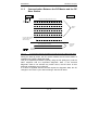
The network is configured with COM 5430 TF/COM 5431 FMS under
SINEC NCM (Network and Communication Management). The configuration
tool can be run on the PG 710, 730, 750 and 770 under the S5-DOS/ST
operating system.
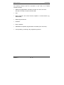
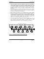
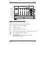
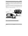
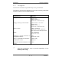
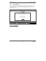
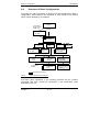
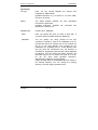
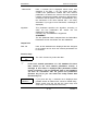
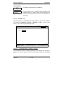
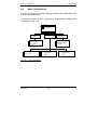
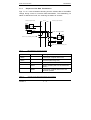
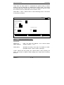
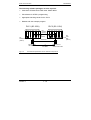
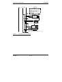
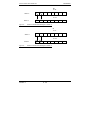
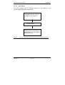
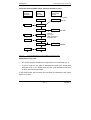
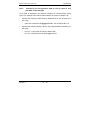
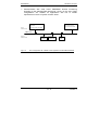
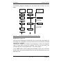
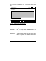
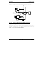
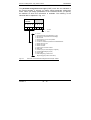
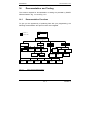
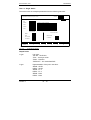
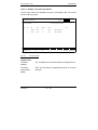
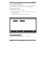
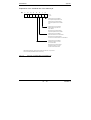
Active SINEC L2 / PROFIBUS stations
S5
CP 5430
SINEC L2/
L2FO
PROFIBUS
PG
CP 5410
Field
device
S5
CP 5430 TF
Field
device
S5
CP 5431 FMS
Field
device
PC
CP 5412
Field
device
o. vendor
device
Passive SINEC L2 / PROFIBUS stations
Bus terminal with line terminator connected
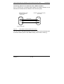
Bus terminal
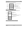
Fig. 1.1
Example of PROFIBUS L2 Configuration
The handling of the communications protocols for layers 1 and 2 described
in this volume is microprocessor-controlled. The host system is therefore
relieved of specific communications tasks.
To allow a wide range of applications, the PROFIBUS communications
system provides the user system with a variety of services for open
communication.
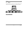
The information in this manual is intended for the following users:
➣ The planner and designer of a communications network
➣ Programmers of communications relations
➣ Customers wishing to use SINEC L2/L2FO in the SIMATIC S5 system
Volume 1
1-2
B8976060/02
Introduction
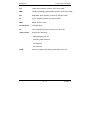
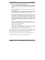
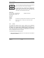
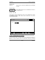
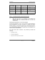
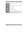
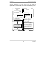
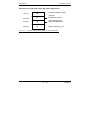
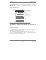
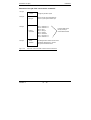
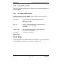
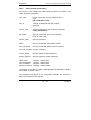
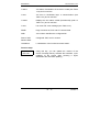
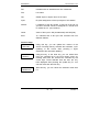
General symbols:
Active star coupler
Twisted pair
Bus terminal (terminating resistor connected)
Bus terminal (terminating resistor disconnected)
DTE
Data Terminal Equipment
Fiber optic cable
Optical bus terminal
SF repeater adapter
R
Table 1.1
✔
☞
mm
RS 485 repeater
Symbols for SINEC L2/L2FO
This character indicates an activity or operation for you to perform.
This symbol highlights special features and dangers.
The dimensions in diagrams and scale drawings are specified in
millimeters.
1-3
Volume 1
Introduction
B8976060/02
Requirements of the user
To understand the examples, you should have the following:
➣ Knowledge of programming with STEP 5
➣ Basic knowledge of the use of handling blocks (HDBs). The description
of the HDBs can be found in the manual for your programmable
controller or in separate descriptions of the programmable controllers.
Training offer
Siemens provides SINEC users with a comprehensive range of training
opportunities.
For more detailed information contact
Informations- and Trainings-Center
für Automatisierungstechnik
AUT 6 Kursbüro
Postfach 21 12 62
76181 Karlsruhe
Germany
or your local Siemens office.
Order numbers for the products mentioned in this manual can be found in
the current catalogs.
Volume 1
1-4
B8976060/02
Introduction
To help you find your way through this manual (Volume 1) the remainder of
this section outlines the chapters briefly.
Chapter 2
System Overview
This chapter supports you when structuring your network and provides an
overview of the standards, techniques, devices and structure of the
PROFIBUS-compatible network SINEC L2/L2FO. You will also find general
information about different topologies, functions and network planning and
design of the SINEC L2/L2FO bus system.
Chapter 3
Fundamentals of the Model
This chapter provides an introduction to the communications model by
explaining terminology and inter-relationships and illustrates the interface to
the SIMATIC S5 user.
Chapter 4
Technical Description and Installation Guidelines for the CP 5430
TF/CP 5431 FMS
This chapter describes in detail the hardware of the CP 5430 TF/CP 5431
FMS (technical data, interfaces, operating statuses, memory modules) and
also deals with PG connections and the module slots in various PLCs.
Chapter 5
Selecting the Type of Communication
This chapter helps you to select the type of communication for your specific
task by briefly outlining the essential characteristics of different types of
communication. The detailed descriptions of the possible types of
communication can then be found in Chapters 7 to 11 in Volume 1 and for
the FMS or TF services in Volume 2. Each chapter contains a specific
description of the basics and of configuration.
1-5
Volume 1
Introduction
B8976060/02
Chapter 6
Basics of Configuration with NCM
This chapter contains an introduction to working with SINEC NCM and
COM 5430 TF/COM 5431 FMS. It is intended to familiarize you with the
basics of configuring, i.e. how to use general guidelines and the basic
configuration screens and their application.
Chapter 7
S5-S5 Communication
This chapter describes the communication with handling blocks on
pre-configured S5-S5 links between active SIMATIC S5 programmable
controllers.
Chapter 8
Free Layer 2 (FL2) Communication
This chapter describes the data exchange with handling blocks using the
layer 2 access of the CP.
The free layer 2 access allows communication with passive and/or
non-Siemens PROFIBUS stations which also have free layer 2 access.
Chapter 9
Global I/Os (GP) Communication
This chapter describes event-driven data transmission using the global I/Os
(GP) via the I/O area of the SIMATIC S5 programmable logic controller.
Chapter 10
Cyclic I/Os (only CP 5430 TF)
This chapter describes the cyclic data exchange to normally passive field
devices using the cyclic I/Os service (ZP) via the I/O area of the SIMATIC
S5 programmable controller.
Chapter 11
Distributed I/Os (DP) Communication
This chapter describes the cyclic communication with standard DP slave
stations via the I/O area of the SIMATIC S5 programmable controller.
Volume 1
1-6
B8976060/02
Introduction
Chapter 12
FMA Services
This chapter describes the different types of communication including a
detailed description of the basics and the configuring procedure. At the end
of each section there is an example to illustrate the type of communication.
Chapter 13
Clock Services
This chapter describes the data formats for the time of day and explains
how the clock master and clock slave roles function.
Chapter 14
Documentation and Test
This chapter contains a description of the test and documentation functions
referred to in earlier chapters
Chapter 15
Utilities
The "bus selection" utility is described in this chapter. This tool is used to
create paths that can be activated using the menu command Bus Selection.
You can also use this tool to modify the memory module size and with the
CP 5430 TF, you can convert databases of the CP 5430 to new databases.
Chapter 16
Using the Application Examples
This chapter describes the general procedure for the application examples.
Chapter 17
Appendix
Here, you will find important information you require regularly, for example
the significance of error messages, basic calculations for important bus
parameters, notes on the simultaneous use of different types of data
transmission etc.
1-7
Volume 1
Introduction
B8976060/02
Chapter A and B
Abbreviations and Index
The list of abbreviations will help you considerably when working with this
manual since you can check the meaning of unknown abbreviations quickly.
You can use the index to find a term quickly.
Chapter C
Further Reading
This section lists publications and manuals dealing with related aspects
(marked in the text with /x/).
Volume 2 of the CP 5431 FMS manual explains the range of functions of
the FMS protocol architecture.
The user interface to the corresponding FMS services is described for
SIMATIC S5.
It provides you with the following information:
➣ Handling
Acyclic communication or
Cyclic communication on the basis of FMS
➣ Documentation and Test
➣ Request Editor
Volume 2 of the CP 5430 TF manual explains the range of communication
with layer 7 (application layer). It describes the user interface to the
corresponding SINEC technological functions (TF) for SIMATIC S5 and for
TF configuration.
This volume provides important information for:
➣ Detailed configuration of the communications processor under TF and
how to configure communication objects (variables, domains etc.)
➣ Operating the interfaces supported by the CP under TF
➣ This volume also introduces the additional packages belonging to the
functional range of the COM system program for menu-guided support
of the TF client interface with the Request Editor. ❑
Volume 1
1-8
B8976060/02
2
System Overview
System Overview
The performance of control systems is no longer simply determined by the
programmable controllers but also to a great extent by the accessory
equipment. Apart from plant visualization, operating and monitoring this also
means a high-performance communications system.
Distributed automation systems are being used increasingly in production
and process automation. This means that a complex control task is divided
into smaller "handier" subtasks with distributed control systems. As a result,
efficient communication between the distributed systems is an absolute
necessity.
Such distributed structures have, for example, the following advantages:
➣ Independent and simultaneous start-up of individual sections of plant
➣ Smaller, clearer programs.
➣ Parallel processing by distributed automation systems
with the following results:
- shorter reaction times
- reduced load on the individual processing units
➣ Supervisory controllers can handle additional diagnostic and logging
functions
➣ Increased plant availability since the failure of a substation does not
stop the whole plant
A comprehensive, high-performance communications system is a must for a
distributed plant structure.
With SINEC, Siemens provides an open heterogeneous communications
system with various local area networks (LANs) for industrial environments.
The SINEC communications system is based on national and international
standards according to the ISO/OSI reference model.
2-1
Volume 1
System Overview
B8976060/02
LANs form the basis of the communications system and can be
implemented
➣ electrically
➣ optically
➣ as an electrical/optical combination.
Volume 1
2-2
B8976060/02
2.1
System Overview
SINEC Overview
SINEC (SIEMENS Network Architecture for Automation and Engineering) is
the name of the communications network for SIEMENS programmable
controllers, process computers workstations and personal computers.
SINEC includes the following:
➣ The communications network comprising the transmission medium, link
and transmission components and the appropriate transmission
technique.
➣ Protocols and services for data transmission between the devices
mentioned above.
➣ The modules of the automation system or computer providing the link to
the communications network (communications processor "CP").
To handle the variety of tasks in automation engineering SINEC provides
different communications networks to suit the particular situation.
The topology of rooms, buildings, factories and complete company
complexes and the prevalent environmental conditions mean different
requirements. The networked automation components also make different
demands on the communications system.
To meet these various requirements, SINEC provides the following
communications networks complying with national and international
standards:
➣ SINEC H3,
a high-speed optical network (FDDI standard).
➣ SINEC H1/H1FO,
a communications network using baseband technology according to
IEEE 802.3 with the CSMA/CD medium access technique operating on
The following media:
2-3
Volume 1
System Overview
B8976060/02
- triaxial cable (50 Ω)
- fiber-optic cable
- twisted pair
➣ SINEC L2/L2FO,
a communications network for the cell and field area according to
PROFIBUS with hybrid medium access techniques token bus and
master-slave operating on
- twisted pair
- fiber-optic cable
The various communications networks can be used either independently of
each other or in different combinations as required.
Volume 1
2-4
B8976060/02
2.2
System Overview
The PROFIBUS-Compatible Network
SINEC L2/L2FO
Within the open, heterogeneous SINEC communications system, SINEC
L2/L2FO is the network for the cell and field area, intended particularly for
industrial environments.
The SINEC L2 network complies with the German process and field bus
standard PROFIBUS DIN 19245.
SINEC L2 is the electrical network based on a shielded, twisted pair.
The optical network SINEC L2FO (FO = fiber-optic) is the optical version
of SINEC L2, i.e. the data transmission between two components (DTE =
data terminal equipment) is on fiber-optic cables.
SINEC L2/L2FO has the following characteristics:
➣ Low installation costs
➣ High flexibility in its communications options, i.e. open communication
by using standards
➣ A variety of possible network topologies using repeaters
The SINEC L2/L2FO bus system can be used in a variety of areas of
application, e.g.
➣ Process engineering
➣ Production engineering
➣ Mechanical engineering
➣ Power engineering
➣ Building automation
2-5
Volume 1
System Overview
B8976060/02
The following devices could be connected to each other via a SINEC
L2/L2FO network:
➣ SIMATIC programmable controllers, S5-95U, S5-115U, S5-115H,
S5-135U, S5-150U, S5-155U and S5-155H
➣ PCs
➣ Motor protection and control devices capable of communication (e.g.
SIMOCODE)
➣ Measuring transducers
➣ Actuators
➣ Field controllers
➣ PROFIBUS-compatible programmable controllers (PLC and CNC)
➣ Local operating, monitoring and programming devices
Volume 1
2-6
B8976060/02
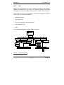
2.2.1
System Overview
Standards
SINEC L2 is based on the reference model of the International Standards
Organization ISO for "Open System Interconnection" (OSI, Fig. 2.1). The
aim of this model is the connection of devices from different manufacturers
via a common "communications system".
The area of application of SINEC L2 bus systems ranges from simple field
bus applications to the networking of production cells (cell bus). In keeping
with this broad area of application, three protocol standards are available
with SINEC L2:
➣ SINEC L2-TF (technological functions)
is suitable for cell networking and allows communication with higher
SINEC H1 networks. /2/ /13/
➣ SINEC L2-FMS (field bus message specification)
is a version intended for networking in the field area with devices of
different manufacturers which comply with Part 2 of DIN 19245. /10/
/12/
➣ SINEC L2-DP (distributed I/Os)
is for the fast connection of distributed I/O systems and corresponds to
DIN E19245 Part 3 PROFIBUS-DP. /11/
All three versions use the PROFIBUS link protocol, i.e. Part 1 of DIN 19245
/1/. All three protocols can be operated simultaneously on a SINEC L2 bus
system, however, communication is only possible between stations with the
same protocol structure.
2-7
Volume 1
System Overview
B8976060/02
SIMATIC S5 provides the following connections for these three protocol
standards:
➣ The SINEC L2-TF connection with the CP 5430 TF
➣ The SINEC L2-FMS connection with the CP 5431 FMS
➣ The SINEC L2-DP connection
CP 5430 TF/CP 5431 FMS.
with
the
IM308
B
and
the
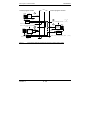
This manual (Volume 1) describes the common functions of the CP 5430
TF/CP 5431 FMS (layer 2). The layer 7 communication of the TF services
on SINEC L2 is described in Volume 2 for each module separately.
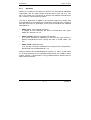
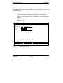
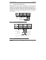
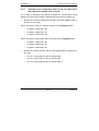
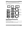
SINEC
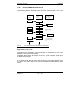
L2-DP SINEC L2-FMS
SINEC L2-TF
USER
PROGRAMS
I/O
I/O
I/O
I/O
Layer
7 Application
CI
User interface
SINEC TF = MMS
SINEC AP
S5S5
FL2
ZP
GP
DP
ALI
FMS
LLI
6 Presentation
empty
5 Session
4 Transport
3 Network
2 Data Link
1 Physical
empty
L2 transport
empty
PROFIBUS standard DIN 19245 T.1
Transmission - Fiber Optic
Fiber optic cable
Fig. 2.1
Volume 1
Layered Structure with SINEC L2/L2FO
2-8
Transmission - RS 485
Shielded twisted pair
B8976060/02
System Overview
The ISO/OSI reference model is divided into 2 different areas:
➣ Transport-oriented layers: 1 - 4
➣ Application-oriented layers: 5 - 7
In SINEC L2/L2FO the lower layers 1 (physical layer) and 2 (data link layer)
comply with the PROFIBUS standard DIN 19245 Part 1. SINEC L2 supports
various transmission techniques (layer 1):
➣ RS-485 transmission technique (complying with the PROFIBUS
standard) /4/
➣ Fiber-optic transmission technique
The medium access control technique (layer 2) in SINEC L2/L2FO is a
hybrid technique operating according to the
➣
Token bus principle for "active stations"
and the
➣ Master-slave principle between "active" and "passive" stations.
Layer 2 provides the standardized FDL interface "Fieldbus Data Link" for
the higher layers. Frames can be processed on this interface with two
different priorities (high, low).
L2 transport as layer 4 provides functions such as segmentation, link
establishment and link termination.
Explanations of the layer 2 communication model for SIMATIC S5 are in
Chapter 3 of this manual (Volume 1) in Chapter 3.
Explanations of the FMS model for SIMATIC S5 are in Volume 2 of the
manual for the CP 5431 FMS.
Explanations of the TF communications model for SIMATIC S5 are in
Volume 2 of the manual for the CP 5430 TF.
2-9
Volume 1
System Overview
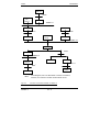
2.2.2
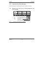
B8976060/02
Network Access Technique
The medium access technique in SINEC L2/L2FO complies with the token
bus technique for active stations and master-slave technique for passive
stations as stipulated in DIN 19245 Part 1.
Active stations
➣ can send data to other stations without being requested to
➣ can request data from other stations.
Passive stations
➣ can only send data after a request from an active station.
Whether or not a station is active or passive depends on the particular
device. Simple field devices, e.g. motor controllers are usually passive,
"intelligent" devices such as programmable controllers, on the other hand,
are normally active. Many devices can be assigned an active or passive
role. The CP 5430 TF/CP 5431 FMS can only be assigned parameters as
an active station.
The access technique is not dependent on the transmission medium.
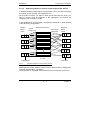
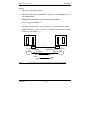
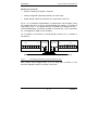
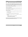
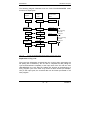
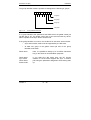
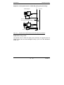
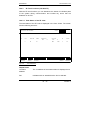
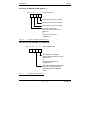
Fig. 2.2 illustrates the hybrid technique with active and passive stations.
This is explained briefly below:
➣ All active stations form the logical token ring in a fixed order, each
active station being aware of the other stations and their order in the
logical ring.
➣ The token (right to transmit) is passed from active station to active
station. The following applies to all active stations: a token rotation
takes place between transmitting the token and receiving it again.
Volume 1
2 - 10
B8976060/02
System Overview
➣ Every active station "knows" the addresses of the other active stations.
An active station checks the address area between itself and the next
active station cyclically, this is known as the GAP address area. With
this check, the station recognizes whether an active or passive station
has been included in the ring or whether a passive station has been
removed.
The GAP update factor specifies the interval at which an active station
checks its complete GAP address area. When a new station is added to
the ring, it receives the token immediately.
➣ When a station has the token, it can transmit providing its token holding
time has not elapsed. The token holding time is calculated according to
a special method each time the token is circulated and indicates how
long the station is permitted to keep or hold the token. If the token
holding time has already elapsed when the token is received, the
station can nevertheless transmit one high-priority frame.
➣ If an active station has the token and if links to passive stations have
been configured, these passive stations are then polled (e.g. read
values) or data is transmitted to them (e.g. transfer of a setpoint).
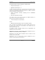
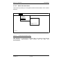
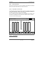
Token rotation (logical ring)
Active stations on bus
DTE
DTE
DTE
DTE
DTE
Master-slave
DTE
DTE
DTE
DTE
DTE
Passive stations on bus
Fig. 2.2
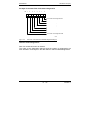
Principle of the SINEC L2 Hybrid Access Technique
2 - 11
Volume 1
System Overview
B8976060/02
Within the token mechanism for the active stations, various procedures are
defined for the following special situations:
➣ Initializing the logical token ring
➣ Duplication of the token
➣ Loss of the token
➣ Addition or deletion of an active station in the logical ring
The way in which the SINEC L2/L2FO network functions results in two
special cases:
1.
When only one station is active and all others are passive, the bus
operates on a master-slave principle.
2.
When all stations are active the technique is token passing.
A token rotation takes a certain amount of time. The maximum permitted
rotation time must be programmed and is known as the target rotation time.
Even when there is a large amount of data traffic, the set target rotation
time must be kept to. To keep within this time, SINEC L2/L2FO uses a
principle explained below.
Volume 1
2 - 12
B8976060/02
System Overview
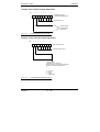
Each station measures the actual token rotation time and calculates the
difference between the target rotation time and the actual rotation time (=
token holding time). During this time, the station can transmit (first the
frames with high priority and then the frames with low priority). Once the
token holding time has elapsed, the token must be passed on.
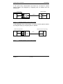
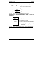
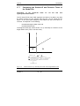
Fig. 2.3
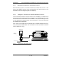
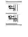
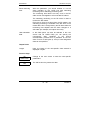
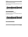
Distribution of the Target Rotation Time (1)
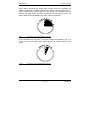
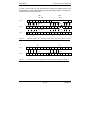
If the transmitter has very little or no token holding time available, (Fig. 2.4)
it can only send one high priority frame before it is forced to pass on the
token.
Fig. 2.4
Distribution of the Target Rotation Time (2)
2 - 13
Volume 1
System Overview
2.2.3
B8976060/02
Transmission Techniques
With SINEC L2/L2FO there are two different transmission techniques
available (RS-485, FO) for two different transmission media (twisted pair or
fiber-optic cable). The SINEC L2/L2FO communications processors (CPs)
generally support both transmission techniques (refer to the manuals for the
specific CPs). The transmission technique is selected along with the SINEC
L2/L2FO bus terminal type.
2.2.3.1
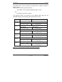
Transmission According to RS-485
The transmission technique RS-485 corresponds to symmetrical data
transmission with NRZ coding according to the USA standard EIA RS-485
/4/. The PROFIBUS standard DIN 19245 Part 1 stipulates RS-485 as
transmission technique version 1 on a twisted pair transmission medium.
The maximum length of a bus segment depends on the data rate and the
cable used.
RS-485 has the following electrical characteristics:
Topology
bus, terminated at both ends by its characteristic impedance; connecting cables to SINEC L2 station
max. 3 m.
Medium:
shielded, twisted pair
characteristic impedance:
loop impedance:
operating capacitance:
attenuation:
wire cross section:
Data rate (dr):
160 Ω
110 Ω
30 nF/km
0.9 dB/100 m (200 kHz)
0.34 mm2
9.6 / 19.2 / 93.75 / 187.5 / 500 / 1,500 Kbps
1,200 m for dr <= 93.75 Kbps
Cable length
(per bus segment): 1,000 m for dr = 187.5 Kbps
400 m for dr = 500.0 Kbps
200 m for dr = 1,500.0 Kbps
Volume 1
2 - 14
B8976060/02
System Overview
(only when using the SINEC L2 bus cable)
Various cables are available from Siemens for SINEC
L2
Number of stations:
max. 32 per bus segment
max. 127 per network when using repeaters
The SINEC L2 bus terminal is used to structure the network. The bus
terminals can be connected to any standardized L2 connector (9-pin sub-D
socket). The pin assignment of the terminal connector corresponds to the
PROFIBUS standard. When supplied, the bus terminal is fitted with a cable
for connection to the CP 5430 TF/CP 5431 FMS communications
processor.
☞
2.2.3.2
For disturbance-free operation with the terminator connected,
the bus terminal requires the 5 V supply voltage from the
DTE. The DTE at the end of the bus must be switched on.
Transmission with Fiber Optic Cables (FO)
The fiber-optic version of SINEC L2 is implemented by an active star
coupler and optical bus terminals. Owing to the physical characteristics of
the fiber-optic cable, SINEC L2FO is structured as a star network.
The data terminal equipment DTEs (e.g. SIMATIC S5 programmable
controllers) are connected to the modules of the active star coupler in
point-to-point links (star) via the bus terminals and glass or plastic
fiber-optic cables.
The length of these point-to-point links depends on the data rate and can be
up to 1400 m long with the SINEC L2FO standard cable 62.5 / 125 µm.
Several active star couplers can be cascaded to form more complex
networks (greater number of DTEs, branched networks, wider spread). The
number of active star couplers that can be connected in series, however, is
reduced at higher data rates.
2 - 15
Volume 1
System Overview
B8976060/02
A point-to-point link between 2 SINEC L2FO bus terminals (without an
active star coupler) is possible.
Characteristics of the fiber-optic technique:
➣ long distance between two DTEs when star couplers are cascaded
(max. 17 x 1.4 km = 23.8 km at dr = 187.5 kbps1)
➣ immune to electromagnetic interference
➣ terminal equipment electrically isolated
➣ supports glass and plastic fiber-optic technology.
The fiber-optic transmission technique has the following characteristics:
Topology:
star network with active star couplers as central components
Medium:
glass fiber-optic cable 62.5/125 µm multimode graded
index
optional 50/125 µm or 100/140 µm multimode graded
index fiber-optic cable
plastic fiber-optic cable 980/1000 µm step index
Data rate (dr):
9.6 / 19.2 / 93.75 / 187.5 / 500 / 1.500 Kbps
Cable length:
0...1.400 m
Cascading depth
23.8 km at 187.5 Kbps 1)
(max. 16 star couplers in cascade)
8.4 km at 500 Kbps 1)
(max. 5 star couplers in cascade)
4.2 km at 1.500 Kbps 1)
(max. 2 star couplers in cascade)
No. of stations:
max. 16 per star coupler
max. 127 per network
1)
for all data rates listed
1) When using the SINEC L2FO standard fiber 62.5 / 125 µm
Volume 1
2 - 16
B8976060/02
System Overview
For more information about fiber-optic cables, refer to Fundamentals, Cable
Technology /5/, VDI/VDE 3692 page 2 /6/ and the SINEC L2/L2FO Network
Manual /9/.
2 - 17
Volume 1
System Overview
B8976060/02
2.3
Network Topology
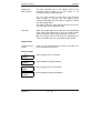
2.3.1
Topology of an Electrical SINEC L2 Network for
the RS-485 Technique
In an electrical SINEC L2 network, the bus cable is a shielded, twisted pair
(SINEC L2 bus cable). The characteristic impedance is 160 ohms. All the
stations are connected to the SINEC L2 bus cable using SINEC L2 bus
terminals. Each SINEC L2 bus segment must be terminated at both ends.
This line terminator is integrated in each bus terminal and is connected in
the two bus terminals at the end of the cable.
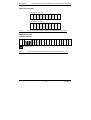
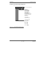
Fig. 2.5 illustrates the typical structure of a SINEC L2 network for RS-485.
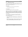
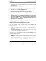
The SINEC L2 topology is a linear bus. By using the SINEC L2 repeater,
several SINEC L2 bus segments can be connected together extending the
SINEC L2 bus system length and increasing the number of stations.
Bus segment
DTE
DTE
DTE
R
DTE
DTE
R
DTE
DTE
Fig. 2.5
DTE
DTE
DTE
DTE
Topology of SINEC L2 for RS-485
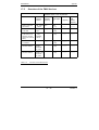
RS-485 allows 32 connections (bus terminals or repeaters) per bus
segment. The maximum length of a segment depends on the data rate
used. The following table (2.1) lists the upper limits for a SINEC L2 bus
cable.
Volume 1
2 - 18
B8976060/02
System Overview
Data rate
9.6
19.2
93.75
187.5
500.0
1,500
Table 2.1
Max. segment length
Kbps
Kbps
Kbps
Kbps
Kbps
Kbps
1.200 m
1.200 m
1.200 m
1.000 m
400 m
200 m
Upper Limits of the Data Rate
Using the repeater as a structuring element, SINEC L2 bus systems can be
implemented in rows and tree structures.
2 - 19
Volume 1
System Overview
2.3.2
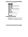
B8976060/02
Topology of an Optical SINEC L2FO Network
Using an active star coupler (AS 501) several stations can be connected
together in a star network ( Fig. 2.6).The connection between the DTE and
the active star coupler or between active star couplers is a plastic fiber-optic
cable (980/1000 µm) or glass fiber-optic cable (62.5/125 µm).The maximum
distance between a DTE and the active star coupler determines the
maximum distance of 2800 m between any two DTEs. By cascading star
couplers, the maximum distance is increased by a further 1400 m with each
active star coupler. Apart from the star coupler, modular fiber-optic
components are available under the name ’optical link module’ (OLM) for
glass and plastic fibers.
DTE
DTE
DTE
*
DTE
*
DTE
DTE
Fig. 2.6
DTE
DTE
Star Couplers with DTEs
By connecting two DTEs directly with a fiber-optic cable, an optical
point-to-point link can be implemented. No active star coupler is required.
The maximum distance between DTEs with glass fiber-optic cables is 1,400
m ( Fig. 2.7).
DTE
DTE
Fig. 2.7
Volume 1
DTEs in a Point-to-Point Link
2 - 20
B8976060/02
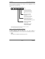
2.3.3
System Overview
Topology of a Combined Electrical / Optical SINEC L2/L2 FO
Network
Using a SINEC L2 RS-485 repeater with an SF optical repeater adapter,
an electrical L2 network (RS-485) can be connected to the active star
coupler of an optical L2 network (see Fig 2.8). It is also possible to connect
two electrical L2 networks optically by means of repeaters with optical
repeater adapters (for interconnecting optical links, see Fig. 2.9). In these
optical point-to-point links, no active star coupler is required.
DTE
R
DTE
DTE
DTE
*
DTE
Fig. 2.8
DTE
DTE
Repeater Connected to Optical Star Coupler with DTEs
DTE
R
DTE
DTE
DTE
R
DTE
Fig. 2.9
DTE
Interconnecting Optical Link
2 - 21
Volume 1
System Overview
B8976060/02
To connect a SINEC L2 repeater to an active star coupler using an SF
optical repeater adapter, the maximum distance of 1400m applies just as for
a direct optical connection between two repeaters using SF optical repeater
adapters.
Volume 1
2 - 22
B8976060/02
System Overview
2.4
Configuring the Network
2.4.1
Configuring a SINEC L2 Network for RS-485
When configuring a purely electrical network the following values are
important:
➣ max. segment length
➣ max. number of stations
➣ max. length of the connecting cables
➣ cascading rules for SINEC L2 repeaters.
Fig. 2.5 shows the typical structure of a SINEC L2 network for RS-485,
comprising several segments connected by repeaters.
Owing to the frequency-dependent attenuation of the cable, the maximum
segment length depends on the data rate. Table 2.1 shows the maximum
segment lengths for a SINEC L2 bus cable.
Number of stations
The maximum number of addressable stations with SINEC L2 (and
PROFIBUS DIN 19245) is 127. A maximum of 32 stations are possible per
bus segment (stations and repeaters).
Connecting cables
The segment lengths indicated here can only be achieved when certain
frequency-dependent capacitances caused by the connecting cables to the
stations are not exceeded. It may be necessary to reduce the total length of
the connecting cables. (see Table 2.2).
2 - 23
Volume 1
System Overview
B8976060/02
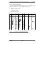
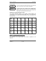
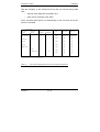
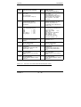
The following connecting cables are permitted for the data rates listed:
Data rate
Max. number of
connectable RS-485 bus
terminals with 1.5 m
connecting cables
Max. number of
connectable RS-485 bus
terminals with 3 m
connecting cables
9.6
Kbps
32
32
19.2
Kbps
32
32
93.75 Kbps
32
32
187.5 Kbps
32
25 *
500
20 *
10 *
6*
3*
Kbps
1500 Kbps
*These values apply to version 1 of the RS-485 bus terminal. On request, there is a
different version of the bus terminal which has no connecting cables, allowing a larger
number to be connected.
Table 2.2
☞
Data Rate and Connecting Cables
Make sure that at data rates 187.5 Kbps, 500 Kbps or 1500
Kbps the total length of the connecting cables does not
exceed 75 m, 30 m or 10 m respectively.
Cascading rules for repeaters
The permitted cascading depth depends on the data rate. At 1500 Kbps, a
maximum of four and at lower rates a maximum of seven repeaters can be
cascaded. A repeater causes a delay of approximately 1.5 bit times. This
delay time which is dependent on the data rate must also be taken into
account when calculating the slot time (refer also to Chapter 6).
Volume 1
2 - 24
B8976060/02
2.4.2
System Overview
Configuring a SINEC L2FO Network
When planning a SINEC L2FO network the following parameters are
important:
➣ maximum signal attenuation/attenuation calculation
➣ cascading rules
You will find detailed information about planning a SINEC L2FO network in
the SINEC L2/L2FO Network Manual /9/. Further reading /7/8/. ❑
2 - 25
Volume 1
NOTES
B8976060/02
3
Fundamentals of the Model
Fundamentals of the Model
To understand the procedure and to be able to work with the system, the
user must be familiar with the model and the terminology. This chapter first
explains the architecture, then the communications model and its
terminology and finally the simulation on programmable controllers.
To keep the explanation of terminology clear, some general terms are
explained in the appendix.
The basic aims of the communication described in this volume are as
follows:
➣ Simple data exchange via layer 2 (ISO/OSI),
➣ Limited volume
performance,
of
transmitted
and
received
data
to
improve
➣ Simple handling.
This model includes two basic types of communication:
➣ Implicit communication is handled in the SIMATIC PLC by means of I/O
bytes, consisting of the distributed I/Os (DP) cyclic I/Os (ZP) and global
I/Os (GP). Implicit communication is controlled by the communications
processor (CP).
The exceptions in this case are the cycle-synchronized communication
modes of the DP, ZP and GP. Here, handling blocks are used for
synchronization.
The cyclic I/Os (ZP) mode is only possible with the CP 5430 TF.
➣ Explicit communication is handled in the SIMATIC PLC by the handling
blocks within the system, consisting of S5-S5, FMA and free layer 2
communication.
3-1
Volume 1
Fundamentals of the Model
3.1
B8976060/02
ISO/OSI Reference Model for Communication
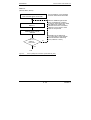
To obtain a structured architecture, the communications tasks were divided
into seven layers (refer to Fig. 3.1). Each device (station) within the network
has the same structure. The layers are hierarchical and each layer provides
a series of services to the next higher layer. With each service, the
executing layer of the local station communicates with the peer layer of the
remote station (logical data exchange). This communication uses a virtual
link with a protocol for the specific layer.
LAYER
7
Application Layer
TASK
Interface to application process,
provides basic functions
6
Presentation Layer
Negotiation of the coding of the data
to be transmitted,
transformation of local into transfer syntax
5
Session Layer
Control of the communication,
Synchronization
4
Transport Layer
Non network-dependent transport service
flow control, fragmentation,
separation of application from the
transport links
3
Network Layer
Routing of traffic within the network,
establishment and termination of links
2
Data Link Layer
Distribution, flow control,
error detection and correction
1
Physical Layer
Transmission and reception of unstructured
bit streams, electrical representation of signals
relevant for CP communication in this volume
Fig. 3.1
Volume 1
The Seven Layers of the ISO/OSI Reference Model
3-2
B8976060/02
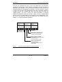
3.2
Fundamentals of the Model
Architecture <-> OSI Environment
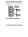
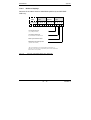
The architecture of the CP 5430 TF is illustrated in Fig. 3.2, that of the CP
5431 FMS in Fig. 3.3, (refer also to Fig. 2.1). The components are briefly
explained after the figures.
in
Vol. 2 (CP 5430 TF)
COM
USER PROGRAMS
I/O
ISO/OSI
Layer
7 Application
6 Presentation
FMA
PG
S5S5
FL2
TF
GP DP ZP
functions
empty
5 Session
4 Transport
3 Network
2 Data Link
1 Physical
L2 transport
L2 transport
CP
empty
empty
PROFIBUS standard DIN 19245 T.1 FDL/MAC/FMA
Technology
Fiber Optic FO
Technology
RS 485
SINEC technological functions (TF) described in Volume 2
Fig. 3.2
Protocol Architecture of the CP 5430 TF
3-3
Volume 1
Fundamentals of the Model
B8976060/02
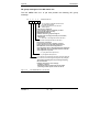
in
Vol. 2 (CP 5431 FMS)
COM
USER PROGRAMS
I/O
ISO/OSI
Layer
7 Application
CI / ALI
FMA
PG
S5S5
FL2
GP
DP
FMS
6 Presentation
functions
LLI
5 Session
4 Transport
3 Network
CP
L2 transport
empty
empty
2 Data Link
1 Physical
PROFIBUS standard DIN 19245 T.1 FDL/MAC/FMA
Technology
Fiber Optic FO
Technology
RS 485
PROFIBUS DIN 19245 T2 (FMS) described in Volume 2
Fig. 3.3
Protocol Architecture of the CP 5431 FMS
Key:
S5-S5:
SIMATIC S5 PLC-PLC communication (Chapter 7)
FL2:
Free layer 2 communication (Chapter 8)
GP:
Global I/Os (Chapter 9)
ZP:
Cyclic I/Os (Chapter 10) CP 5430 TF
DP:
Field bus management layer (Chapter 11) CP 5430 TF/CP 5431 FMS
FMA:
Field bus management layer (Chapter 12)
FDL:
Field bus data link
the services belonging to layer 2 are also known as FDL
(field bus data link) services
Volume 1
3-4
B8976060/02
Fundamentals of the Model
LLI:
Lower layer interface (Volume 2) CP 5431 FMS
FMS:
Fieldbus messaging specification (Volume 2) CP 5431 FMS
ALI:
Application layer interface (Volume 2) CP 5431 FMS
CI:
Cyclic interface (Volume 2) CP 5431 FMS
MAC:
Media access control
L2-Transport:
Transport layer
TF:
Technological functions (Volume 2) CP 5430 TF
PG functions:
Used for the following:
- loading/deleting the CP
- executing COM functions
- bus selection
- test functions
COM:
Used to configure and assign parameters to the CP
3-5
Volume 1
Fundamentals of the Model
3.2.1
B8976060/02
Communications Model
This section is intended to introduce you to the communications world and
to provide explanations of the model and terminology to establish the
relationship between theory and practice.
In terms of communication, an application process includes all the
programs, resources and tasks not assigned to a communication layer.
These include, for example, operating systems, real application processes,
application programs and communication drivers.
3.2.1.1
Relationship between Application Processes
There are logical relationships between application processes which are
used to exchange information. These communication relations must all be
established before data exchange begins. An application process can
participate in communication via communication end points. One or more
communication end points are assigned on a fixed basis and uniquely to an
application process. These are addressed by the application process using
local communication references (address of the communication end point).
The communication references are specific to a device. Between two
application processes, there are one or more communication relationships
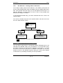
which are uniquely assigned to communication end points (see Fig. 3.4).
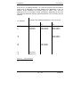
1 O
Application
Communication
relation
process A
20 O
9
O
Communication
end point no. 20
Application
process
C
Fig. 3.4
Volume 1
O 7
Application
process B
O22
O 12
Relationship Between Application Processes
3-6
B8976060/02
3.2.1.2
Fundamentals of the Model
Logical Data Exchange
FDL services are available for issuing jobs. Jobs are transferred via the
specified communication relations (logical channels as connection) to the
communication partner in PDUs.
DEVICE X
Data exchange
Application
process
transparent
DEVICE Y
Application
process
Layer 2
2
2
1
1
physical data
transmission
Fig. 3.5
Logical Data Exchange
To the user, it appears as if the application processes exchange data
directly. In fact, the data are passed down from layer 2 on one side,
transmitted on the physical medium and passed up again to layer 2 through
the communications layers.
3.2.2
Communication Relations
From the point of view of the user, communication with the application
processes of the communication partner takes place on logical channels.
These logical channels to the communication partners are defined in the
configuration phase.
For each communication relationship the following information is stored:
➣ address of the remote station
➣ local and remote service access point
3-7
Volume 1
Fundamentals of the Model
B8976060/02
The communications start and end point of a logical channel between two
stations on the bus is known as a Service-Access Point (SAP). A SAP is a
further address criterion in addition to the station address. You must specify
a SAP number for each channel to be able to use layer 2 services.
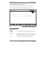
3.2.2.1
Addressing Model for Explicit Communication
(for S5-S5, free layer 2 and FMA)
An interface to the user process is specified for SIMATIC S5 by the
interface number and job number.
In the CP itself, a job is identified and managed using only the job number
(Fig. 3.6).
Process A
ANR
1 2 3
Process B
ANR
4 5 6
Process C
ANR
7 8 ...
Job numbers
all unique
PLC
ANR
SSNR
1,3
0
4, 5, 6
2
2
1
8. ...
7, ...
3
n
CP
SAP
11,13
22
34, 35, 36
L2 address 2
47
48
L2 bus
Fig. 3.6
Addressing Model for Communication on the CP
The assignment of the job number to the SAP must be unique both (local
and remote). When configuring the CP 5430 TF/CP 5431 FMS, the
communication relations to other stations must be specified.
Volume 1
3-8
B8976060/02
3.2.2.2
Fundamentals of the Model
Addressing Model for Implicit Communication (GP, DP ZP)
In data transmission using implicit communication via L2, the data exchange
is handled via the I/O area of the SIMATIC PLC.
All I/O bytes via which you want to send and all I/O bytes via which you
want to receive must be assigned to the appropriate I/O protocol by
configuring the I/O areas in COM.
In GP (global I/Os) communication, I/O bytes are assigned to global objects
of the GP during configuration.
Sending
station
Unique
assignment
active
PLC
CP
PLC
CP
PLC
CP
PLC
Non-unique
assignment
CP
Output areas
Fig. 3.7
Global objects (GOs)
Receiving
station
active
CP
PLC
CP
PLC
CP
PLC
CP
PLC
CP
PLC
"L2 bus"
Input areas
Addressing Model for Communication with GP
Sending and receiving stations must be active. Both functions, sending and
receiving are possible in one station.
Communication is via global objects which form the connection (the "bus").
3-9
Volume 1
Fundamentals of the Model
B8976060/02
In ZP (cyclic I/Os) communication (CP 5430 TF), I/O areas of certain
passive stations are assigned by configuring their L2 address and the
remote SAP.
Active station
Input area
Passive station
CP
Input
buffer
L2 bus
PLC
Output
area
Fig. 3.8
SAP
SAP
Output
buffer
Field
device
Addressing Model for Communication with ZP
In DP (distributed I/Os) communication, I/O areas of certain passive stations
are assigned simply by configuring their L2 address.
Station active (DP master)
Input
area
PLC
Output
area
Fig. 3.9
Volume 1
Station passive/active (DP slave)
CP
DP polling
list
L2 bus
Input
area
Output
area
Addressing Model for Communication with DP
3 - 10
Field
device
B8976060/02
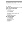
3.3
Fundamentals of the Model
Application Interfaces of Layer 2 Communication
In this model, as already mentioned, there are two basic types of
communication:
Explicit communication using the existing handling blocks:
➣ S5-S5 communication
➣ Free layer 2 communication
➣ FMA services.
Implicit communication using I/O bytes:
➣ Global I/Os (GP)
➣ Cyclic I/Os (ZP) with the CP 5430 TF
➣ Distributed I/Os (DP).
3.3.1
3.3.1.1
Explicit Communication
S5-S5 Communication
With this type of communication, the CP generates frames from the data
records of the SIMATIC S5 PLC which meet the requirements of the
PROFIBUS standard (Part 1). The services of the first layer and the
FDL-SDA (send data with acknowledge) service of the second layer of the
ISO/OSI reference model are used. Communication between SIMATIC S5
PLCs is achieved using HDBs via S5-S5 links. The job numbers 1 to 32 are
available for transmit jobs via layer 2 and 101 to 132 for receive jobs. The
links to be established between the maximum 32 active stations on SINEC
L2 (static SAP relationships), can be configured with the aid of the COM.
The size of the frames is restricted to a maximum of 128 bytes.
With this type of data transmission, you do not need to know about PDU
structure or service IDs, since the CP does the encoding. To control
3 - 11
Volume 1
Fundamentals of the Model
B8976060/02
communication with the SIMATIC S5 PLC, it is necessary to check and
evaluate the status words of the HDB during the communication.
The basic sequence of communication via S5-S5 links is described in
Chapter 7 .
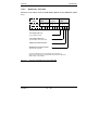
STATION 1
STATION 2
PLC
PLC
CP
CP
transmitted
Data to be
received
in data block (DB)
in data block (DB)
Data to be
HDB
SEND
ANR 1
ANZW
Job active
Fig. 3.10
3.3.1.2
B
U
F
F
E
R
SDA frame
Acknowledgment
B
U
F
F
E
R
SAP 3
station
address
SAP 2
station
address
HDB
RECEIVE
ANR 101
ANZW
Job complete with/
without error, data
acceptance successful
Handling an S5-S5 Link
Free Layer 2 Communication with FDL Services
For communication with passive or active and heterogeneous stations on
the SINEC L2 bus, the CP provides a free access to layer 2.
With this type of data transmission, it is valuable to understand the services
of layer 2 of the model.
Volume 1
3 - 12
B8976060/02
Fundamentals of the Model
The layer 2 firmware of the CP provides various services for reliable data
transmission which you can use in the control program. In concrete terms,
this means that you request layer 2 services for data transfer and evaluate
confirmations (including error messages) made available by this layer in the
control program. You must also evaluate layer 2 indications when a frame is
received by the CP.
The FDL services specified in PROFIBUS (DIN 19245/1) and implemented
in the CP for data transmission are as follows:
➣ FDL_DATA.-req/-ind/-conf (SDN service)
➣ FDL_DATA_ACK.-req/-ind/-conf (SDA service)
➣ FDL_DATA_REPLY.-req/-ind/-conf (SRD service)
➣ FDL_SEND_UPDATE.-req/-ind/-conf (RPL_UPD_S)
➣ FDL_REPLY_UPDATE.-req/-ind/-conf (RPL_UPD_M).
You use these services provided by the layer 2 firmware of the CP in your
STEP 5 control program by calling handling blocks which refer to job
buffers. The job buffer (PDU) must be completed by the user. The first 8
bytes ("header") of the job buffer to be transferred contain control
information for the layer 2 firmware. The receiver can evaluate the first 8
bytes of the received block of data as status information (this also includes
error messages).
With the data transmission services SDA, SDN and SRD, the CP
5430 TF/CP 5431 FMS uses the control information from the header of the
block of data to "pack" the data in a frame which can then be transmitted
via the SINEC L2 bus. The remaining 242 bytes are available for the user
data when transmitting and receiving.
3 - 13
Volume 1
Fundamentals of the Model
B8976060/02
The basic procedure for communication with the free layer 2 access is
described in Chapter 8.
The job numbers ANR 134 to ANR 186 are available for these layer 2
functions.
3.3.1.3
Fieldbus Management with FMA Services
The FMA services are provided on the CP 5430 TF/CP 5431 FMS for
service and information purposes. The execution of an FMA service
corresponds to that of an FL2 service. The following reading (passive) FMA
services are available to the user on the CP:
➣ FDL_READ_VALUE
➣ LSAP_STATUS
➣ FDL_LIFE_LIST_CREATE_LOCAL
➣ FDL_IDENT
➣ FDL_READ_STATISTIC_CTR
➣ FDL_READ_LAS_STATISTIC_CTR.
To start an FMA service, the job buffer (8 byte "header") must be
transferred to layer 2. The data for the job are then returned in the
confirmation.
The basic procedure for the FMA services using FL2 access is described in
Chapter 12. The special job number ANR 200 is available for these
management functions.
Volume 1
3 - 14
B8976060/02
3.3.2
Fundamentals of the Model
Implicit Communication
If you use implicit communication, the communications processor (CP)
controls the communication. The types of communication in DP, ZP and GP
in which communication is synchronized with the cycle and for which
handling blocks are used to update information are exceptions.
The difference between GP and DP/ZP is as follows:
➣ GP is used for communication only between active stations
➣ DP/ZP is used for communication between an active and a passive
station.
➣ DP data exchange is only controlled by one master (polling).
3 - 15
Volume 1
Fundamentals of the Model
3.3.2.1
B8976060/02
Global I/Os (GP)
The term "global I/Os" means that part of the I/O area is not used by I/O
modules but for global data exchange between SIMATIC PLCs. Global data
exchange involves the CP sending the entire changed output area assigned
to the global I/Os and cyclically updating the entire input area assigned to
the global I/Os with the received data once again. The global I/O area is in
the I/O area of the controller and is also used by the PLC program. The
address areas are processed with STEP 5 operations. The mode can either
be synchronized with the cycle or free. With the cycle-synchronized mode, a
CP-HDB must be called at the checkpoints required by the user to ensure
the consistency of inputs and outputs. This HDB also triggers a group job
for data transmission.
An important characteristic of global I/Os is that changes in the data bytes
are recognized and only the changes transmitted.
This data transmission is suitable for the transfer of single bytes between
active SIMATIC S5 programmable controllers.
The CP 5430 TF/CP 5431 FMS uses the SDN transmission service to
transmit the data "packed" in a frame via the SINEC L2 bus.
The basic procedure for this communication is explained in Chapter 9.
Volume 1
3 - 16
B8976060/02
3.3.2.2
Fundamentals of the Model
Cyclic I/Os (ZP), only with CP 5430 TF
The demanding requirements of cyclic communication for automation
functions of a field device cannot be met by direct HDB calls. Instead of
cyclic HDB calls, the CP 5430 TF also provides the POLL or cyclic I/Os
service.
The term "cyclic I/Os" means that part of the I/O area is not used by I/O
modules, but rather for cyclic data exchange between SIMATIC
programmable controllers and passive stations. "Cyclic data exchange"
involves the CP 5430 TF transmitting the entire output area assigned to the
cyclic I/Os and updating the entire input area assigned to the cyclic I/Os
with the received data cyclically. The cyclic I/O area is in the I/O area of the
controller and is also used by the PLC program. The address areas are
processed with STEP 5 operations. The mode can either be synchronized
with the cycle or free. With the cycle-synchronized mode, a CP-HDB must
be called at the checkpoints required by the user to ensure the consistency
of inputs and outputs. This HDB also triggers a group job for data
transmission.
ZP data transmission is suitable for communication between SIMATIC S5
PLCs and field devices. Field devices are passive stations which cannot
access the bus themselves and must then be constantly or cyclically polled
by active L2 stations.
The CP 5430 TF uses the SRD transmission service to send data to the
slave stations on the SINEC L2 bus.
The basic procedure for this communication is described in Chapter 10
3 - 17
Volume 1
Fundamentals of the Model
3.3.2.3
B8976060/02
Distributed I/Os (DP)
Data transmission using L2-DP (distributed I/Os) provides a standardized
interface for communication between SIMATIC S5 PLCs and field devices
(DP slave), with the PROFIBUS DP protocol complying with DIN E19245
Part 3.
Data transmission with DP is simple to implement.
The programming and handling is reduced to a minimum for the user. When
using the DP service, part of the I/O area of the PLC is occupied by the
connected DP slaves. The CP 5430 TF/CP 5431 FMS structures the I/O
bytes used in the direction of the CPU.
This means that access by the user program to the I/O bytes used by
L2-DP is acknowledged by the CP 5430 TF/CP 5431 FMS.
Using the L2-DP protocol, the CP 5430 TF/CP 5431 FMS exchanges the
input and output data assigned to the individual DP slaves cyclically.
The basic sequence of this communication is described in Chapter 11.❑
Volume 1
3 - 18
B8976060/02
Technical Description and Installation of the CP 5430 TF/CP 5431 FMS
4
Technical Description and Installation of
the CP 5430 TF/CP 5431 FMS
4.1
Technical Description
4.1.1
Communications Processor CP 5430 TF/CP 5431 FMS
The elements of the CP 5430 TF/CP 5431 FMS important for operation can
be seen in Fig. 4.1.
The description of the indicators and interfaces can be found on the
following page.
X5
X5
S1
X1
S1
H1/H2
H1
H3
H2
H3
X4
Eprom 2
..
..
.
..
..
..
..
X4
..
..
..
..
.
X3
Eprom 1
X3
SPC
X2
X6
70325
X8
X7
X9
X7
DC/DC converter 24V - 5V
Fig. 4.1
Design of the CP 5430 TF/CP 5431 FMS
4-1
Volume 1
Technical Description and Installation of the CP 5430 TF/CP 5431 FMS
Explanation of Fig. 4.1:
Mode indicator
H1 : RUN (refer to Table 4.1)
H2 : STOP (refer to Table 4.1)
H3 : CP-FAULT (refer to Table 4.2)
Mode selector switch:
S1 : STOP/RUN (refer to Table 4.1)
Interfaces:
X1 : backplane connector (refer to Table 4.3)
X2 : backplane connector (refer to Table 4.3)
X3 : L2 interface (refer to Table 4.4)
X4 : PG interface (AS511) (refer to Table 4.5)
X5 : slot for memory submodule
X6 : medium connector (intended for extensions)
X7 : L2FO interface, provides FO link for plastic fiber optic cable
X8 : test jumper
X9 : test jumper
Eprom 1/2:
contains the firmware for the CP 5430 TF/CP 5431 FMS
Volume 1
4-2
B8976060/02
B8976060/02
4.1.1.1
Technical Description and Installation of the CP 5430 TF/CP 5431 FMS
Mode Indicators (RUN and STOP LEDs)
Table 4.1 explains the significance of the RUN and STOP LEDs
Mode changes
The mode can change in a variety of situations. Fig. 4.2 illustrates the
factors causing a particular change.
FROM
Actions
TO
RUN
STOP
NOT
SYNCHRON
- Set STOP/RUN switch on front panel of CP 5430 TF/
CP 5431 FMSto RUN.
- Trigger PG function "START CP" (only when mode switch
is set to RUN).
During the STOP -> RUN transition, all pending jobs
are deleted.
RUN
Synchron HDB call in a start-up OB of the programmable
controller; STOP/RUN switch on the front panel of the
CP 5430 FMS set to RUN.
RUN
STOP
NOT
SYNCHRON
RUN or
STOP
- Set START/STOP switch on front panel of the CP
from RUN to STOP.
- trigger PG function "stop CP".
STOP
- Set START/STOP switch on front panel of the CP
from RUN to STOP.
- Trigger PG function "stop CP".
NOT
SYNCHRON
Only after power outage:
- the programmable controller is in the STOP
mode
or
- No SYNCHRON HDB in start-up OB
Fig. 4.2
Mode Changes
4-3
Volume 1
Technical Description and Installation of the CP 5430 TF/CP 5431 FMS
B8976060/02
LED
Status of the
CP 5430 TF/
CP 5431 FMS
Meaning
Green
RUN LED
lit, red unlit
RUN
- All types of data transmission are possible,
both from the CPU control program and via
PG bus functions.
- The memory submodule of the CP 5430 TF/CP
5431 FMS can be read, but not written to.
Red STOP
LED lit,
green unlit
STOP
- HDB data exchange between CP and CPU
via the backplane bus blocked (evaluation of
the PAFE error message possible: refer to
Section 7.3.2 or 8.1.3).
- CP can be assigned parameters via AS 511
interface (memory submodule can be written to).
- Data exchange via PG bus function possible,
management services possible.
Green
RUN LED
and red
STOP
LED lit
NOT
SYNCHRON
- No data transmission possible
(data exchange with the CPU via the
backplane bus blocked).
- CP cannot be assigned parameters via the
AS 511 interface.
- The memory submodule of the CP 5430 TF/CP
5431 FMS can be read but not written to.
Cause: HDB SYNCHRON run incorrectly.
Remedy: call HDB SYNCHRON.
Neither
green
RUN LED
nor
STOP
LED lit
Table 4.1
Volume 1
Cause:
- POWER OFF
- CP not correctly plugged in.
- Fault indicated by the fault LED
(refer to Table 4.2).
Result: no data transmission possible
(data exchange with the CPU via the
backplane bus blocked).
Meaning of the LEDs
4-4
B8976060/02
Technical Description and Installation of the CP 5430 TF/CP 5431 FMS
The START /STOP response
The CP is a slave processor system in the S5 rack and must therefore
follow the START/STOP response of the master (here the PLC). After
switching on the power supply, the CP runs through a hardware test
program. Following this, it sets up a management block in the non-backed
up RAM area for every job defined in the module card for internal program
management. It then waits for the start signal from the PLC. In this idle
status, all the programs which process the system tasks or operate the PG
interface are released, however, data exchange with the PLC or with the
bus system is blocked.
The STOP status is defined as follows:
➣ The system programs and the PG interface are enabled.
➣ The virtual links remain established, or continue to be established.
➣ Data transfer on the bus system and interfaces to the PLC are blocked.
The RUN status is defined as follows:
➣ All the programs of the CP and interfaces to the PLC are enabled.
➣ The PG interface is enabled and all ONLINE PG functions can be
performed (exception: changing the database).
➣ Data transfer is enabled and can be monitored with the COM test
functions.
The CP runs through a warm restart whenever the status changes from
STOP to RUN and from RUN to STOP and to RUN again
(resynchronization by repeatedly activating the START/STOP switch on the
PLC). All previously established links are cleared and then re-established.
All buffered data on the CP is lost during this status change
With the COM functions START CP and STOP CP, the PG can also set the
START or STOP request. A STOP status triggered with the START/STOP
switch can only be changed with the START/STOP switch.
4-5
Volume 1
Technical Description and Installation of the CP 5430 TF/CP 5431 FMS
4.1.1.2
B8976060/02
Fault LED
The fault LED is lit permanently or flashes when the firmware of the CP
detects an error (refer to Table 4.2).
Note: when the CP fault LED flashes/is lit, the RUN and STOP LEDs are
irrelevant!
LED
Meaning
Fault LED
flashes
- No data transmission possible (data exchange with the
CPU via the backplane bus blocked).
- Parameters can be assigned on the AS 511 interface.
- Data exchange using PG bus functions not possible.
- User module detected as invalid during start-up.
- Management services remain possible.
Possible causes:
- memory submodule fault/error
- firmware and configuration not compatible
The COM test functions provide further diagnostic tools (refer to
Section 12.2).
flashes 2x
Too many links programmed.
flashes 3x
Memory problem (not enough resources) ot incomplete
database (OB1 missing)
flashes 4x
SAP configuration incorrect (e.g. configured twice).
flashes 5x
Incorrect bus parameters.
flashes 6x
Incorrect application associations (layer 7).
flashes 7x
DP slave parameter assignment error
CP fault LED
lit
Hardware fault.
Tabelle 4.2
Volume 1
Meaning of the Fault LED
4-6
B8976060/02
4.1.2
Technical Description and Installation of the CP 5430 TF/CP 5431 FMS
Data Exchange between the CPU and CP 5430 TF/CP 5431
FMS
The following section explains how the CP 5430 TF/CP 5431 FMS receives
data for transmission from the CPU and how it passes on data it has
received to the CPU.
The following programmable controllers of the SIMATIC S5 family are
supported:
➣ S5-115U with CPU 942, 943, 944, 941B, 942B, 943B, 944B, 945
➣ S5-115H
➣ S5-135U (single and multiprocessor system) with CPU 922, 928, 928B
➣ S5-155U (single and multiprocessor system) with CPU 922, 928, 928B,
946/947, 948
➣ S5-155H.
Depending on the type of data transmission, the CPU and CPs in the same
PLC exchange data in different ways:
➣ Using the I/Os
➣ Using job buffers and the dual-port RAM
Data exchange via I/Os
With data transmission using GP/DP/ZP (refer to Chapters 9 and 10 and
11) the data exchange takes place using the I/O address area. Depending
on the address, this area in the STEP 5 control program can either be
addressed via the process image of inputs and outputs (PII and PIQ) or
directly.
☞
This data exchange is only possible using the base interface
number of the CP (see Fig. 4.3). R In the multiprocessor
mode, data exchange via I/Os is only possible with CPU 1
(other CPUs have no access to the base interface).
4-7
Volume 1
Technical Description and Installation of the CP 5430 TF/CP 5431 FMS
B8976060/02
Data exchange using the job buffers of the dual-port RAM
With S5-S5 data transmission and free layer 2 access (refer to Chapters 7
and 8) data is exchanged using the dual-port RAM of the CP 5430 TF/CP
5431 FMS. All data and functions passing through the dual-port RAM of the
CP 5430 TF/CP 5431 FMS must be provided by handling blocks from the
point of view of the control program.
The principle of the PLC-CP link
The interface between CPs and the PLC is a dual-port RAM (DPR) which is
organized in the same way in all S5 CPs. The CP 5430 TF/CP 5431 FMS
has four such DPR interfaces so that in multiprocessor PLCs each central
processing unit (CPU) can communicate with the CP independently of the
others. The STEP 5 user program controls the CP via the DPR using
handling blocks (HDBs). The STEP 5 user cannot access CPs directly
(without using handling blocks). The following system calls (i.e. HDBs) are
available:
➣ SEND
transfer data to the CP
➣ RECEIVE
receive data from the CP
➣ RESET ALL
warm restart on the module
➣ CONTROL
request the status of a job
➣ SYNCHRON
start up and synchronize the PLC and CP
All these handling blocks must be assigned an interface number and a job
number (SYNCHRON only requires an interface number).
The job number (ANR) identifies both a task on the CP and in the PLC.
On the CP, the job number also involves a parameter set which defines the
assignment to a virtual circuit, the data direction and the priority class.
Volume 1
4-8
B8976060/02
Technical Description and Installation of the CP 5430 TF/CP 5431 FMS
The interface number (SSNR) consists of the base interface number and
the page number of the CP.
For the data exchange between the CP 5430 TF/CP 5431 FMS and the
PLC-CPU a 4 Kbyte dual-port RAM (DPR) is available which is divided into
4 pages each of 1 Kbyte.
In the address area of the CPU, the memory area F400H ... F7FFH (1
Kbyte) is available for addressing the dual-port RAM of CPs/IPs with page
addressing. To allow more than one CP/IP to use this memory area to
exchange data with a CPU, the page numbers must not overlap. To ensure
a unique assignment, the pages as seen by the PLC are numbered from 0
to 255.
The CP 5430 TF/CP 5431 FMS always occupies 4 pages, beginning with
the page number assigned to it with the "base interface number" parameter.
For this reason, the base interface number beginning at 0 can only be set in
steps of 4 (0, 4, 8, 12, ..., 248).
The grouping of pages into four for the CP is only necessary with the
multiprocessor PLCs to prevent the page numbers overlapping which would
result in double addressing (refer to Fig. 4.3).
In the multiprocessor PLCs, the assignment of CPU and page number is as
illustrated in Fig. 4.3.
Multiprocessor PLCs
0
1
2
3
CPU3
base SSNR 4
CP 1
Fig. 4.3
4
CPU4
5
6
CP 2
7
...
base SSNR 248
base SSNR 0
CPU2
base SSNR 8
CPU1
Interface Addressing with a Multiprocessor PLC
4-9
Volume 1
Technical Description and Installation of the CP 5430 TF/CP 5431 FMS
B8976060/02
For monoprocessor PLCs, it makes sense to use only the base interface
number (refer to Fig. 4.4).
Monoprocessor PLCs
0
1
2
3
base SSNR 4
4
CP 1
5
6
CP 2
7
...
base SSNR 248
base SSNR 0
base SSNR 8
CPU
pointless
Fig. 4.4
Interface Addressing with a Monoprocessor PLC
The link between the STEP 5 user program and a particular action on the
CP is the SSNR/ANR combination. To prevent the system reacting
incorrectly, an ANR must only be assigned once per connected CP. Fig. 4.5
illustrates the relationship between a STEP 5 user program and the
parameter set on the CP.
Volume 1
4 - 10
B8976060/02
Technical Description and Installation of the CP 5430 TF/CP 5431 FMS
PLC
CP
DPR
(HDB call in
user program)
SSNR x+1
SEND
x
y
SSNR x
SSNR
ANR
Link block
ANZW
QTYP
DBNR
QANF
QLAE
SSNR x
ANR y
PAFE
Link
parameters
Job buffer
Link to another
station on the
SINEC L2 bus
Status
bits
Fig. 4.5
☞
4.1.2.1
Assignment: Calls in the User Program -> Parameter Lists on the CP
For more details about handling blocks for the individual
PLCs (particularly when the blocks are integrated in the
operating system) refer to the descriptions of the relevant
programmable controllers
Hardware Monitoring (Watchdog)
If an error occurs in the module which cannot be corrected by the firmware,
the hardware monitoring (watchdog) responds and resets the module (cold
restart).
4 - 11
Volume 1
Technical Description and Installation of the CP 5430 TF/CP 5431 FMS
4.1.3
Technical Data of the CP 5430 TF/CP 5431 FMS
4.1.3.1
Interfaces
PG interface:
TTY
max. 1 km long
transmission protocol Siemens AS 511
9.6 Kbps
L2 interface:
RS 485
L2FO interface:
Plastic HP duplex
☞
4.1.3.2
B8976060/02
The L2FO interface and the 9-pin RS 485 connector must
never be both connected at the same time. If the L2FO
interface is not being used, it must be closed with the rubber
plug supplied. Light falling on the receiver diode can cause
disturbances.
Operating and Environmental Conditions
Type of protection:
IP00
Permitted ambient
temperature:
0 ... 55 °C
Permitted storage
temperature:
- 40 ... + 70 °C
Humidity class:
F complying with DIN 40040
(15 ... 95 % no condensation at 25 °C)
Operating altitude:
up to approx. 3,000 m above sea level
Volume 1
4 - 12
B8976060/02
4.1.3.3
Technical Description and Installation of the CP 5430 TF/CP 5431 FMS
Mechanical and Electrical Data
Current consumption:
5V
typically 450 mA
24 V
typically 70 mA for RS 485
Power loss:
1.9 W for RS 485
5.3 W at 5V2/500 mA
Back-up current:
typically 20 pA
Vibration:
10 ... 57 Hz 0.15 mm; 57 ... 150 Hz 2 g complying
with IEC 68-2-6
Electrical isolation:
no
Weight of the
module
approx. 0.4 kg
Weight of the
approx. 0.1 kg
memory submodule:
Card size:
double Eurocard format (160 x 233.4 mm)
Front panel width:
20.32 mm (1 1/3 standard slot)
4.1.3.4
Logical Characteristics
Static RAM 384 Kbytes
DPR 4 Kbytes, 4 pages each 1024 bytes
EPROM 384 Kbytes (maximum)
4 - 13
Volume 1
Technical Description and Installation of the CP 5430 TF/CP 5431 FMS
4.1.3.5
B8976060/02
Performance Data CP 5430 TF
S5-S5
Maximum number of links:
32
Maximum amount of data:
128 bytes per job
Free Layer 2
Maximum number of links:
Maximum amount of data:
32 (55 without S5-S5)
242 bytes per job
ZP (cyclic I/Os)
Max. polling list entries:
128
Maximum number of job:
242 bytes per ZP slave
(max., however 256 bytes in total)
Maximum number of outputs:
242 bytes per ZP slave
(max. however 256 bytes in total)
GP (global I/Os)
Maximum number of GP objects:
2048 throughout the network
Maximum number of inputs:
256 bytes per station
Maximum number of outputs:
64 bytes per station
Maximum number of stations:
32
If ZP and GP are used together, a maximum of 256 inputs and 256 outputs
can be used.
Volume 1
4 - 14
B8976060/02
Technical Description and Installation of the CP 5430 TF/CP 5431 FMS
DP (distributed I/Os)
Number of DP slaves per master:
32
Maximum number of inputs:
242 bytes per DP slave
(max. however 256 bytes in total)
Maximum number of outputs:
242 bytes per DP slave
(max. however 256 bytes in total)
TF (technological functions)
Maximum no. of application associations
24 for PDU size 512 bytes
Maximum PDU size:
9999 bytes
Maximum number of configurable
variables:
of which max. 242
defined variables per scope
800
242 VMD-specific
242 domain-specific
242 per application association
Maximum name length:
☞
32 bytes
Simultaneous operation of DP, GP and ZP is not possible.
The total number of SAPs (links) required for S5-S5/free layer
2 and TF must not exceed 55.
4 - 15
Volume 1
Technical Description and Installation of the CP 5430 TF/CP 5431 FMS
4.1.3.6
B8976060/02
Performance data of the CP 5431 FMS
ALI
Number of links:
32
Number of variables
(indexes):
approx. 256
Maximum length
of a variable:
233 bytes
Maximum PDU size:
241 bytes (data: 233 bytes)
Link attributes:
master-master and master-slave
(without slave initiative)
No connectionless services
CI
Number of links:
32
Maximum PDU size:
32 bytes
Maximum number of inputs:
232 bytes per CI slave (max. however
256 bytes in total)
Maximum number of outputs:
232 bytes per CI slave (max. however
256 bytes in total)
DP (distributed I/Os)
Maximum number of DP slaves
per Master:
32
Maximum number of inputs:
242 bytes per DP slave (max. however
256 bytes in total)
Maximum number of outputs:
242 bytes per DP slave (max. however
256 bytes in total)
Volume 1
4 - 16
B8976060/02
Technical Description and Installation of the CP 5430 TF/CP 5431 FMS
GP (global I/Os)
Maximum number of GP objects:
2048 throughout the network
Maximum number of inputs:
256 bytes per station
Maximum number of outputs:
64 bytes per station
Maximum number of stations:
32
If CI and GP are used together, a maximum of 256 inputs and 256 outputs
can be used.
☞
1. The specifications for CI only apply when no ALI links are
programmed (MMAC, MSAC).
2. The sum of ALI and CI links must not exceed 48.
3. The number of possible ALI links (MMAC, MSAC) can be
reduced by the following:
the number of CI links
the number of job numbers per communication reference
the number of entries in the "access to variables" field of
the communication references (Get OL).
4. Simultaneous operation of DP and CI is not permitted.
5. Simultaneous operation of GP and CI is not possible.
4 - 17
Volume 1
Technical Description and Installation of the CP 5430 TF/CP 5431 FMS
4.1.3.7
B8976060/02
Interface Assignments
This section specifies the electrical interfaces of the CP 5430 TF/CP 5431
FMS (refer to Tables 4.3 - 4.5). The interfaces are as follows:
➣ Backplane connector X1/X2
➣ L2 interface socket X3
➣ PG interface socket X 4
X1
Pin
no.
D
Signal
name
B
Signal
name
Z
Signal
name
X2
Pin
no.
D
Signal
name
B
Signal
name
Z
Signal
name
2
4
6
8
10
12
14
16
18
20
22
24
26
28
30
32
UBATT
ADB12
ADB13
ADB14
ADB15
IRA
IRB
IRC
IRD
ODSI
-
M5
ADB0
ADB1
ADB2
ADB3
ADB4
ADB5
ADB6
ADB7
ADB8
ADB9
ADB10
ADB11
BASP
M5
P5
MEMR
MEMW
RDY
DB0
DB1
DB2
DB3
DB4
DB5
DB6
DB7
-
2
4
6
8
10
12
14
16
18
20
22
24
26
28
30
32
TxD
-
M5
RxDs
M5
P5
NAU
M24
P24
Table 4.3
Volume 1
Pinout Table of the Backplane Connectors X1 and X2
4 - 18
B8976060/02
Technical Description and Installation of the CP 5430 TF/CP 5431 FMS
L2 interface socket X3 (RS 485)
Table 4.5
X3
Pin
no.
Signal
name
PROFIBUS
designation
1
2
3
4
5
6
7
8
9
PE
SIL
RxD/TxD-P
RTS (AG)
M5V2
P5V2
BATT
RxD/TxD-N
RTS (PG)
Protective earth
Data line - B
Control - A
Data ref. potential
Power supply +
Data line - A
Control - B
occ. with
RS 485
yes
yes
yes
yes
yes
yes
-
Pinout Table of the L2 Interface Socket X3
PG interface socket X4
Table 4.4
X4
Pin
no.
Signal
name
1
2
3
4
5
6
7
8
9
10
11
12
13
14
15
M-EXT (external ground))
TTY INP24
MASSE (internal ground))
TTY OUT+
TTY OUTM-EXT (external ground))
TTY IN+
M24
20 mA (control source for transmitter))
MASSE (internal ground)
20 mA (control source for receiver))
Master poll
MASSE (internal ground))
Pinout Table of the PG Interface Socket X4
4 - 19
Volume 1
Technical Description and Installation of the CP 5430 TF/CP 5431 FMS
B8976060/02
4.2
Memory Submodules
4.2.1
Memory Submodule Types for the CP 5430 TF/CP 5431 FMS
To store the parameter data in the CP 5430 TF/CP 5431 FMS, the following
memory submodule types can be used:
Type of submodule
Type
Memory capacity
EPROM NMOS/CMOS
376
16Kbytes x 8
EPROM NMOS/CMOS
376
32Kbytes x 8
EPROM NMOS/CMOS
376
64Kbytes x 8
RAM
377
16Kbytes x 8
RAM-Modul
377
32Kbytes x 8
RAM
377
64Kbytes x 8
Table 4.6
Volume 1
Memory Submodules Available for the CP 5430 TF/CP 5431 FMS
4 - 20
B8976060/02
Technical Description and Installation of the CP 5430 TF/CP 5431 FMS
4.3
Installation Guidelines
4.3.1
Basic Configuration
Fig. 4.6 illustrates the minimum configuration of a SINEC L2 bus system.
➣ Communications processor CP 5430 TF/CP 5431 FMS
➣ Bus terminal with terminal cable
➣ Bus cable
P
L
C
C
P
.
PG
interface
(AS 511)
C
P
L2
interface
bus cable
.
Bus terminal 1
with terminal cable
Fig. 4.6
4.3.1.1
Bus terminal 2
with terminal cable
SINEC L2 Components
CP 5430 TF/CP 5431 FMS Slots in the various PLCs
The CP 5430 TF/CP 5431 FMS communications processor is designed as a
board in double Eurocard format. The front panel is 1 1/3 standard slots
wide.
The CP 5430 TF/CP 5431 FMS can be used in the CP slots of the PLCs
listed in Section 4.1.2.
The module is supplied in a compact design and can be operated without a
fan. If the module is to be inserted in the S5-115U, an adapter casing is
required.
4 - 21
Volume 1
Technical Description and Installation of the CP 5430 TF/CP 5431 FMS
☞
B8976060/02
Modules must only be inserted or removed when no voltage
is applied. The rules for working with electrostatically
sensitive devices (ESD guidelines) must be adhered to.
Depending on the range of performance and the configuration of the control
system, there are several subracks available for the central controller (CC)
(S5 115U) and for expansion units (EU).
The slot assignments in SIMATIC PLCs are as follows:
SIMATIC S5 115U
Central controllers:
Subrack CR 700-0LB. .
C
P
U
P
S
0
1
2
3
I
M
Subrack CR 700-2LA. .
C
P
U
P
S
0
1
2
4
3
5
6
I
M
1
2
4
3
5
6
I
M
Subrack CR 700-3LA. .
C
P
U
P
S
0
CP 5430 TF/CP 5431 FMS slots in the S5-115U
CP 5430 TF/CP 5431 FMS slots in the S5-115U
which must left free when no fan is used
Fig. 4.7
Volume 1
Slots for the CP 5430 TF/CP 5431 FMS in the S5-115U 115U
4 - 22
B8976060/02
Technical Description and Installation of the CP 5430 TF/CP 5431 FMS
Expansion unit (EU):
Subrack ER 701-3LA..
PS
0
1
2
3
4
5
6
7
IM
4
5
6
7
IM
Subrack ER 701-3LH..
PS
Fig. 4.9
0
1
2
3
Slots for the CP 5430 TF/CP 5431 FMS in the Expansion Unit ER 701-3L
SIMATIC S5-135U
Central controller
3
11
19
27
35 43
51
59
67
75
83
91
99
107 115 123 131 139 147 155 163
without interrupt line
Fig. 4.8
Slots for the CP 5430 TF/CP 5431 FMS in the Central Controller CC 135U
4 - 23
Volume 1
Technical Description and Installation of the CP 5430 TF/CP 5431 FMS
B8976060/02
SIMATIC S5-155U
Central controller:
3
11
19
27
35
43
51
59 67
75
83
91
99 107 115 123 131 139 147 155 163
without interrupt line
Fig. 4.10
Slots for the CP 5430 TF/CP 5431 FMS in the Central Controller CC 155U
In the S5 155U, in certain situations (Manual S5-155U) further slots may be
available for the CP
Expansion unit EU 185U:
3
11
19
Fig. 4.11
27
35
43
51
59
67
75
83
91
99
107 115 123 131 139 147 155 163
Slots for the CP 5430 TF/CP 5431 FMS in the Expansion Unit EU 185U
Expansion unit EU 186U:
3
19
Fig. 4.12
Volume 1
35
51
67
83
99
115
131
147
Slots for the CP 5430 TF/CP 5431 FMS in the Expansion Unit EU 186U
4 - 24
163
B8976060/02
Technical Description and Installation of the CP 5430 TF/CP 5431 FMS
SIMATIC S5-135U/155U
3
11
19
27 35
43
51
59 67
75
83
91
99 107 115 123 131 139 147 155 163
without interrupt line
Fig. 4.13
Slots for the CP 5430 TF/CP 5431 FMS in the Central Controller CC 188U
4 - 25
Volume 1
Technical Description and Installation of the CP 5430 TF/CP 5431 FMS
4.4
B8976060/02
Ways of Connecting PGs on the SINEC L2 Bus
With the following L2 communications processors you can connect a PG or
a PC/AT directly to a bus terminal and therefore to the L2 bus.
Product name
Application
Functions
CP 5410-S5DOS/ST
PG 730 / 750 / 770
with STEP5/ST
PG functions via SINEC
L2/L2FO
CP 5410-S5DOS/MT
PG 730 / 750 / 770
with STEP5/MT
PG functions via SINEC
L2/L2FO
TF-NET 5412/MSDOS,
Windows
PG 730 / 750 / 770
AT-compatible PCs
with MSDOS or
WINDOWS
FDL functions (layer 2)
TF functions (layer 7)
Table 4.14
Possible Connections
Connection of PGs to programmable controllers with CPs is possible in
various ways depending on the configuration and application.
The simplest case is direct connection of the PG to the CP (refer to Fig.
4.15).
Volume 1
4 - 26
B8976060/02
Technical Description and Installation of the CP 5430 TF/CP 5431 FMS
If there are several CPs in one rack as for example in the multiprocessor
PLC S5-135U, the modules can be connected using the PG-MUX 757.
C
P
U
.. .
. .. ... ...
PG interface
(AS 511)
Programmer
(PG 710, PG 730, PG 750, PG770)
Fig. 4.15
Direct Connection from the PG to the CP
4 - 27
Volume 1
Technical Description and Installation of the CP 5430 TF/CP 5431 FMS
B8976060/02
If several PLCs are networked with one SINEC L2 bus system, you can
also program the CPUs via the bus. In practice, this means that a centrally
installed PG, e.g. in a control room, can reach all the PLCs connected to
the bus system.
With the SINEC L2 bus system, the following programmers can be used:
PG 710, PG 750, PG 730 and PG 770. The PGs are operational when they
are connected using the PG interface (AS 511) of the CP 5430 TF/CP 5431
FMS.
If you want to connect a PG 730, 750 or 770 directly to the bus, the
products shown in Table 4-14 must be used.
CP
L2 interface
Point to point link
between CP and CPU
C
P
U
}
.. .
. .. ... ...
.
Bus terminal 2
with terminal cable
.
Bus cable
Bus terminal 1
with terminal cable
Fig. 4.16
Volume 1
Communication Path PG/CPU on the SINEC L2 Bus System
4 - 28
PG interface
(AS 511)
B8976060/02
4.4.1
Technical Description and Installation of the CP 5430 TF/CP 5431 FMS
Structure and Functions of the Bus Terminal
Bus terminals connect a CP 5430 TF/CP 5431 FMS, CP 5412 or a CP
5410 to the SINEC L2 bus. As the end terminal, they also function as the
terminator of the bus segment (refer to Chapter 2).
4.4.2
Example of Transmission with RS 485 Bus Terminals
The RS 485 bus terminal connects devices with a SINEC L2 interface and
which use the RS 485 transmission technique to the SINEC L2 bus. If the
bus terminal is the last station on the SINEC L2 bus, a terminating resistor
can be switched in (switch setting "bus terminated"). These bus terminals
are suitable for all data rates.
One version of the RS 485 bus terminal has a PG/OP interface (see Fig.
4.17). This bus terminal allows the connection of PGs and OPs to the bus
without additional wiring.
Small device
PG/OP
interface
.
......
Fig. 4.17
...
Bus Terminal with PG/OP Interface
4 - 29
Volume 1
Technical Description and Installation of the CP 5430 TF/CP 5431 FMS
B8976060/02
Connecting cable for bus terminals with a PG/OP interface
Fig. 4.18 shows the connecting cable between the PG/OP interface of the
RS 485 bus terminal and the interface of the CP 5410 (PG).
PG/OP interface* of the
RS 485 bus terminal
(9-pin male)
.. ..
.. ...
Interface * of the CP 5410 (PG)
(9-pin male)
5
9
4
8
3
7
2
6
1
.. ..
.. ...
5
RXD/TXD(A)
RXD/TXD(B)
PE
9
4
8
3
7
2
6
1
* View of solder side
Fig. 4.18
Cable Between PG/OP Interface and CP 5410
You can order a specially prepared connection cable for bus terminals with
a PG/OP interface (refer to the SINEC catalog for the order number).❑
Volume 1
4 - 30
B8976060/02
5
Selecting the Type of Communication
Selecting the Type of Communication
Chapter 3 explained that there are various mechanisms available for data
transmission that can, in practical terms, be divided into five different types
as follows:
➣ Data transmission with HDBs on links (S5-S5)
➣ Data transmission with HDBs by direct access to layer 2 services (FL2)
➣ Data transmission with global I/Os (GP)
➣ Data transmission with cyclic I/Os (ZP) with the CP 5430 TF
➣ Data transmission with distributed I/Os (DP)
This chapter contains basic information about the different types of
communication to help you select the type of data transmission most
suitable for your applications.
Criteria influencing the selection of the type of data transmission are as
follows:
➣ Speeds necessary for the data transmission (performance)
➣ Size of the messages
➣ Number and type of communications partners
➣ Monitoring mechanisms
➣ Priority of the transmission
Section 5.6 provides a brief overview of SINEC TF. Volume 2 of the CP
5430 TF manual contains the complete description of communication with
SINEC TF and the services available.
5-1
Volume 1
Selecting the Type of Communication
B8976060/02
Chapter 5.7 provides a brief overview of SINEC FMS. In Volume 2 (CP
5431 FMS), you will find the complete description of communication with
SINEC FMS and the services available.
Volume 1
5-2
B8976060/02
5.1
Selecting the Type of Communication
Data Transmission with HDBs (S5-S5)
Data transmission with HDBs on configured links is suitable for the
transmission of related blocks of data up to 128 bytes long between active
SIMATIC S5 programmable controllers.
This type of communication has the following characteristics:
➣ The data transmission is via S5-S5 links configured in the PLC program
and triggered by HDBs.
➣ The station relationship is a 1 : 1 relationship between two stations:
station 1 (PLC<->CP) -----> (CP<->PLC) station 2.
➣ The data structures to be transmitted are related blocks of data of 1 to
128 bytes.
➣ The PLC cycle time load as transmitter and receiver is high compared
with implicit communication (GP/ZP/DP).
➣ The L2 service used is SDA.
➣ The priority of the L2 frame can be selected: L (low) / H (high) / I (high
with interrupt).
Special features:
A frame with the priority I (interrupt) can trigger an interrupt in the remote
PLC.
5-3
Volume 1
Selecting the Type of Communication
5.2
B8976060/02
Data Transmission with HDBs (Free Layer 2
Access)
This type of data transmission is suitable for communication between
SIMATIC S5 programmable controllers and remote PROFIBUS compatible
automation or field devices. SIMATIC S5 programmable controllers can also
communicate with each other with this type of data transmission, although
for this situation, data transmission via S5-S5 links is much easier to handle
(refer to Chapter 7).
With data transmission by direct access to layer 2 services, you can
transmit or receive blocks of data with a length of maximum 242 bytes.
This type of communication has the following characteristics:
➣ The data transmission is by direct access to layer 2 services after being
triggered by an HDB in the PLC program.
➣ The station relationship is a 1 : 1 relationship or a 1 : n relationship
between stations: station (PLC<->CP)----->(CP<->PLC) or non-S5
device station.
➣ The data structures to be transmitted are related blocks of data of 1 to
242 bytes.
➣ The PLC cycle time load as transmitter and receiver is high compared
with implicit communication (GP/ZP/DP).
➣ The L2 service used is SDA, SDN, SRD, RPL_UPD_S, RPL_UPD_M.
Depending on the type of service selected, various security
mechanisms accompany the data transmission.
➣ The priority of the L2 frame is selectable (L (low) / H (high)).
Volume 1
5-4
B8976060/02
5.3
Selecting the Type of Communication
Data Transmission with Global I/Os (GP)
Data transmission with global I/Os (I/O interface) is suitable for
communication between SIMATIC S5 PLCs. The data transmission using
global I/Os is suitable for the transmission of single bytes between active
SIMATIC S5 programmable controllers. Data with the following
characteristics can be transmitted:
➣ Small volumes of data
➣ Time-critical data
➣ Data with few changes.
This type of communication has the following characteristics:
➣ The data transmission takes one of the two following forms:
–
synchronized with the cycle, triggered by the PLC program using
the I/Os (the PLC determines when the data transmission takes
place), or
–
free, initiated by the CP using the I/Os (the CP determines when
the data transmission takes place).
➣ The station relationship is a 1 : n relationship :
1 station (PLC<->CP) -----> n stations (CP<->PLC).
➣ The priority of the L2 frame is H (high).
➣ The data structures to be transmitted are as follows: for all stations
there are a maximum of 2048 GP bytes (GPB 0...GPB 2047) available
(per station a maximum of 64 GP output bytes and 256 GP input bytes).
5-5
Volume 1
Selecting the Type of Communication
B8976060/02
Special features:
With this type of communication, the base interface is always used. Data is
only transmitted when the status of bytes has changed. If you use GP,
global objects must also be configured on the CP as well as the
input/output bytes.
☞
Configured I/O bytes must not overlap the addresses of
inserted I/O cards.
Volume 1
5-6
B8976060/02
5.4
Selecting the Type of Communication
Data Transmission with Cyclic I/Os (ZP)
(CP 5430 TF)
Data transmission with cyclic I/Os is suitable for communication between
SIMATIC S5 PLCs and PROFIBUS compatible field devices. The field
devices are passive stations that cannot access the bus themselves and
must normally be polled cyclically by active L2 stations.
The "cyclic I/Os (ZP)" type of data transmission is easy to use, i.e. far less
programming is required compared with the other types of data
transmission, for example the "free layer 2 access" (Chapter 8).
This type of communication has the following characteristics:
➣ The data transmission takes one of the two following forms:
–
synchronized with the cycle, triggered by the PLC program using
the I/Os (the PLC determines when the data transmission takes
place)
or
–
free, initiated by the CP using the I/Os (the CP determines when
the data transmission takes place).
➣ The station relationship is a 1 : 1 relationship:
station (PLC<->CP) <-----> station
➣ The data structures to be transmitted are related blocks of data of 1 to
242 bytes.
Special features:
With this type of communication, the base interface is always used.
5-7
Volume 1
Selecting the Type of Communication
5.5
B8976060/02
Data Transmission with Distributed I/Os (DP)
Data transmission via L2-DP (distributed I/Os) provides a standardized
interface for communication between SIMATIC S5 PLCs and field devices
(DP slaves).
Data transmission with DP is simple to handle.
For the user, the programming and handling is reduced to a minimum.
When using the DP service, part of the I/O area of the PLC is occupied by
the connected DP slaves with the CP modeling the I/O bytes towards the
CPU. This means that access by the user program to the I/O bytes used for
L2-DP is acknowledged by the CP.
Using the L2-DP protocol, the inputs and outputs assigned to the individual
DP slaves are exchanged cyclically by the CP (see Chapter 11).
This type of communication has the following characteristics:
➣ Data transmission uses one of the following two methods:
–
Synchronized with the cycle, determined by the STEP 5 control
program.
–
Free, initiated by the CP (no influence by the STEP 5 control
program).
➣ The CP can only be operated as DP master of class 1 on the SINEC L2
bus.
➣ The L2-DP interface of the CP operates according to the PROFIBUS
standard DIN E 19254, Part 3.
Special features:
With this type of communication, the base interface is always used.
Volume 1
5-8
B8976060/02
5.6
Selecting the Type of Communication
Communication with TF (CP 5430 TF)
Owing to its complexity, TF communication is discussed in detail in Volume
2 (CP 5430 TF). This section simply provides an overview of the services
available and their advantages. For more information about the model and
programming, refer to Volume 2 (CP 5430 TF).
The SINEC technological functions (TF) form the application protocol (layer
7 ISO/OSI) for communication in a heterogeneous automation network with
the CP. They provide the user with services to allow problem-free
interaction between different automation components (e.g. PLC, NC
controls, robots, open-loop controllers, PCs, mini-computers and host
computers etc.). TF services also allow the exchange of information
(messages) using a standard language. In contrast to data-oriented
protocols in which "pure bits" are transmitted, in message-oriented protocols
contents are transmitted. The standardization is intended to permit the
implementation of open systems, reducing the time and expense required
for the software engineering. A further advantage is the monitoring of the
application association.
The basis on which the TF services are defined is the international standard
for application protocols in the area of industrial automation:
ISO 9506, MMS (Manufacturing Message Specification).
The uniform, standardized language for exchange of information has
the following advantages:
➣ The use of TF services for the exchange of information makes the job
of the programmer much easier. The protocol "disguises" the specific
characteristics of the end system behind a standardized, uniform
representation of the system and the data. This means that negotiations
between programmers regarding system structures and methods of
representation are no longer necessary. The programmer can
concentrate on implementing his own particular tasks
➣ The simple integration of components of other manufacturers is made
possible by TF.
➣ The protocol is independent of the underlying communication system:
SINEC L2, SINEC H1 or SINEC MAP. This provides flexibility in
5-9
Volume 1
Selecting the Type of Communication
B8976060/02
program development (the system grows with the requirements of the
user) and also means a reduction of training costs.
➣ Bridges can be implemented without problems.
➣ By using TF, the time and expense of software development can be
greatly reduced.
Advantage of using the TF infrastructure
➣ Increased reliability with logical acknowledgment of messages.
➣ Chronological and logical monitoring of the TF jobs.
TF services:
➣ Variable services: To ensure continuity despite different end systems,
the data is simulated on variable objects.
➣ Application association management: To manage communication
relations between applications.
➣ VMD services: To obtain information about the programmable logic
controller.
Further functions::
➣ Clock services: To synchronize the time of day throughout the
network.
Volume 1
5 - 10
B8976060/02
5.7
Selecting the Type of Communication
Communication with FMS (CP 5431 FMS)
FMS communication is discussed in detail in Volume 2 (CP 5431 FMS).
Here, there is only a overview of the services available. For further
information about the model and configuring, refer to Volume 2 (CP 5431
FMS).
SINEC L2-FMS (Fieldbus Messaging Specification), is the version for
application with the completely standardized PROFIBUS.
The interface of the CPs to FMS can be divided into the following:
–
Cyclic interface (CI)
–
Application layer interface (ALI)
➣ Data transfer with cyclic communication (using CI)
This type of communication is always suitable when values only need to
be written or read cyclically. The jobs to be processed cyclically are
specified during configuration. Only the variable values are exchanged
between the PLC and CP. The CP creates the appropriate FMS-PDUs
automatically.
➣ Data exchange with acyclic communication (using ALI)
☞
This type of communication is advantageous when the
services used and the time they are used is controlled by the
user program. Job buffers containing a job description and
possibly also data are exchanged between the PLC and CP.
The PDU is created based on the content of the job buffer.❑
5 - 11
Volume 1
NOTES
B8976060/02
6
Basics of Configuration
Basics of Configuration with NCM
To configure the CP you require the corresponding software package COM
5430 TF/COM 5431 FMS, simply called COM from now on, which can be
run on all PGs with S5-DOS Stage VI (or higher) or on PC/ATs with
S5-DOS Stage VI. The COM under SINEC NCM (Network and
Communication Management) allows menu-controlled programming of all
the required parameters for the CP. A distinction is made between
parameters which do not depend on the type of data transmission (basic
configuring) and parameters which depend on the selected type of data
transmission. The documentation and test functions are explained in
Chapter 14.
This chapter introduces you to the basics of configuring, configuring the
individual types of data transmission is discussed in the chapters dedicated
to the specific type.
To familiarize you with handling the software package, the following topics
are introduced in this chapter:
➣ The structure of SINEC NCM and how to work with it.
➣ The structure of the COM screens and how to use them.
➣ The procedure for installing the software package.
➣ The structure and procedure for basic programming.
➣ The transfer of files to/from the CP or PLC and the required
preparations.
6-1
Volume 1
Basics of Configuration
6.1
B8976060/02
SINEC NCM
To make it easier to handle the increasing number of different configuring
and test tools, SINEC COM products now have the management interface
SINEC NCM. SINEC NCM is the menu manager which unites the COMs of
completely different end systems under one user interface.
The SINEC NCM user interface has the following characteristics:
➣ Configuring is made more understandable and clearer by the method of
representation.
➣ The menu guidance is based on the SAA standard with keyboard
shortcuts and cursor operation (mouse operation from S5-DOS/ST
Stage VI onwards).
➣ Settings made in the project currently being worked on are saved in
their up-to-date status and are reconstructed when you return to the
project.
➣ Operation and input with various COMs is standardized.
➣ Specially selected hierarchical steps provide an easy overview.
Volume 1
6-2
B8976060/02
6.1.1
Basics of Configuration
The Keyboard
Functions are executed using standard keys or key combinations.
The following list shows the assignment of the most commonly used COM
functions to the keys on the PG/PC keyboard.
COM functions
Keyboard
Paging, searching for files backwards
<Arrow up> or one of the
function keys
"page-1" "line-1" or
mouse click on the function key
Paging, searching for files forwards
<Arrow down> or one of the
function keys
"page+1" "line+1" or
mouse click on the function key
Return or abort
<ESC> or break key
mouse click on "End" field in the
upper right corner of the input screen
Enter
<F7> or enter key
mouse click on F7
Selection, i.e. possible parameters are
displayed for selection
<F8>
mouse click on F8
Help, i.e. input fields now have direct
help texts for the user
<HELP> (PG)
SHIFT F8
Delete the information displayed on the
screen
<DEL>
☞
Other key assignments may be possible depending on the
PC/PG you are using.
6-3
Volume 1
Basics of Configuration
6.1.2
B8976060/02
Menu Structure and Operation
This chapter briefly explains the structure, functions and operation of SINEC
NCM.
The user interface is designed so that a menu bar is displayed in which you
can see all the function groups as a menu item, which provides for
programming and testing. The bottom edge of the screen contains the help
line, in which a specific help text is available for each pull-down menu item
(explanation see Fig. 6.1). The area between the menu bar and the help
line is for the user dialog. Here, the pull-down menu items, help texts,
special windows etc. are displayed.
Menu item
Menu
bar
{
=
Context
Init Edit
Pull-down
menu
opened
CP XXX
Functions
{
Example 1
Example 2 >
Example 3
Example 4
Test 1
Test 2
Test 3
Test 4
Pull-down menu items
*
}
> i.e.: second pull-down
menu exists
Second pull-downmenu opened
* i.e. menu item cannot be
activated at present
Help line text
Help
line
Test 3 can be activated
{
highlighted i.e. activated
E
Fig. 6.1
Volume 1
highlighted letter or number (hotkey),
i.e. menu item selection possible by typing this character
SINEC NCM Screen Layout
6-4
B8976060/02
Basics of Configuration
➣ Explanation of the menu bar and the individual pull-down menus.
From the menu bar you can obtain all the menu items. The menu items
in the menu bar represent a group of functions. The pull-down menu
items represent the operations or commands used to activate the individual COM function screens. The NCM selection menu is no longer
visible when a COM function screen has been activated by a pull-down
menu item.
If you select a pull-down menu item marked with an arrow tip (>), you
obtain a further pull-down menu in which you can select other pull-down
menu items.
Pull-down menu items marked with an asterisk (*) are disabled.
➣ Selecting pull-down menu items (i.e. commands):
When you select a menu item in the menu bar with the arrow keys, you
automatically open the corresponding pull-down menu. After this, you
select a menu item with the arrow keys and then press <enter>. To
activate a menu point you can also use the keyboard shortcut, i.e. the
highlighted letter in the menu item title. You can, for example, select the
Edit menu from the menu bar with <E> and the Init command from the
pull-down menu with <I>. You can terminate every action with the
<ESC> key and return to the previous menu. After you activate the
item, the corresponding COM screen is opened. Once you have completed work with the screen, you return to SINEC NCM.
➣ From S5-DOS/ST Stage VI onwards, you can also select menu items
with the mouse. In this case, you select menu items with the mouse
pointer. The actions are activated with the suitable keyboard operation
or by pressing the left mouse button.
6-5
Volume 1
Basics of Configuration
6.1.3
B8976060/02
COM Screen Layout and Operation
The COM software is operated exclusively via screens and softkey menus.
The softkey menus display the possible branches and functions that can be
triggered by the function keys F1 to F8.
The four cursor keys (arrow keys left, right, up, down) are used to position
the cursor within a screen. The input fields in the screens are completed
using the ASCII keyboard. The OK key validates the string you have input.
The cancel or ESC key returns you to the previous screen or aborts the
currently active function.
Dialog screen explanation
Screen name
Title
bar
{
Context
CP x x x
Source:
Explanation screen
CP type:
CP0000
File name:
Test
Output field
Input field
Comment text
Message line
{ This is a message
{
F
F
F
F
F
F
F
1
2
3
4
5
6
7
F
OK
8 SELECT
Function keys
Fig. 6.2
Screen Layout
The line on the screen above the softkeys is the message line. Here, the
PG displays warnings, errors, operating instructions etc. A message
remains displayed until you press a key.
Volume 1
6-6
B8976060/02
Basics of Configuration
Screen title bar:
Screen name:
Description of the path in abbreviated form, e.g. "Init
Edit"
Context:
Screens specific to the CP: name of the CP otherwise
SINEC NCM
Source:
Module file/bus parameter file/path name
Message line:
Current messages are described in the line above the softkeys (warnings,
errors, operating instructions etc.). A message remains displayed until you
press a key.
Keys:
Function keys F1 to F8 for activating functions.
General information about input:
Highlighted field:
If the input field is displayed in inverse video,
modifications or inputs can be made. You can delete
the input fields character by character by using the
special key "crossed out zero".
Field not
highlighted:
This is purely a display field.
General notes on operation:
➣ You can only make inputs or changes in highlighted fields selected with
the cursor positioning keys.
➣ To obtain a list of possible selections, press F8 (Select).
➣ After you have made your selection with the cursor keys you can enter
it with <CR> or the OK key.
➣ With the help key on the PG and SHIFT F8 on the PC, you can obtain
a help text explaining your selection.
6-7
Volume 1
Basics of Configuration
B8976060/02
➣ Once you have processed a screen completely and want to enter the
data, press F7 or the enter key to transfer the data to the database
displayed as the "source".
<ESC> discards your entries and aborts the function.
Volume 1
6-8
B8976060/02
6.1.4
Basics of Configuration
Special Windows
These windows are used by NCM to provide help and information and are
displayed automatically or after selecting a pull-down menu item of the
INFO menu item ’=’.
Explanatory screen
Special window
This is a help text
or
a copyright display
OK
This is a message
F
F
F
F
F
F
F
1
2
3
4
5
6
7
Fig. 6.3
F
OK
8 SELECT
Special Window
6-9
Volume 1
Basics of Configuration
6.2
B8976060/02
Installation and Start
Free working memory capacity of at least 590 Kbytes is required to use
SINEC NCM.
Make sure that you have enough free space on the hard disk. You should
make approximately 1.2 Mbytes of hard disk available per COM (see the
Readme file). When you install the COM under MS-DOS, the installation
tool checks that there is sufficient space.
Procedure:
✔ Start the operating system.
✔ Insert the COM diskette in a floppy disk drive.
✔ Change to your installation diskette e.g.: >A.
✔ Activate the installation routine on the installation diskette, e.g.: >install
c:\SINEC i.e.: the software is installed from drive A: to drive C:\SINEC
in the SINEC directory. The directory (in this example SINEC) must
already exist.
☞
Protect the files you have transferred from being accidentally
overwritten.
Volume 1
6 - 10
B8976060/02
Basics of Configuration
✔ Call the command interpreter (KOMI) with >S5, then press the <insert>
or <OK> key.
–
Selecting the package under S5 DOS stage V
Activate SINEC NCM in the KOMI screen with the "package
selection" key <F1> (or <Insert> or OK) (for more detailed
information, refer to the S5-DOS manual).
–
Selecting the package under S5 DOS stage VI
Under the "OTHERS" menu item, you can navigate to the COM
5430/5431 directory. If you selected the correct path, the COM can
be started with the OK key.
After activating SINEC NCM, a window displaying the copyright appears
and after acknowledging this window you can begin working with SINEC
NCM.
☞
Please remember that the databases configured in the
following sections are stored in the default working directory
under S5 DOS stage VI.
6 - 11
Volume 1
Basics of Configuration
6.3
B8976060/02
General Guidelines for Working with your Software
When designing your bus system, follow the procedure outlined below:
➣ Find out how many PLCs and field devices are required for your
application. Assign the L2 station addresses carefully since renaming
the L2 station addresses once you have configured them is time
consuming.
➣ All the configuration data should be stored in one file, i.e. whenever
possible, work "OFFLINE FD" with the PG hard disk.
Creating user files
As already mentioned, the CP 5430 TF/CP 5431 FMS has a receptacle for
a memory submodule. These submodules can be RAMs or EPROMs.
Depending on the particular submodule, 16 Kbytes to 64 Kbytes of memory
are available (for memory submodules refer to Section 4.2). The CP
expects to find the description of a link and the general parameters (user
data) in this memory submodule.
For the system-wide identification (S5 system) of submodules, there is a
system identification block (Edit -> CP Init: SYSID).
There are two ways of configuring (making entries/modifications) in the Init
-> Edit screen:
OFFLINE FD: you create the blocks on disk and transfer the created
parameter set directly to a RAM submodule using the transfer function
Transfer -> CP Database Transfer -> FD -> CP. The transfer function is
only possible when the CP is in the STOP mode (Transfer -> Start CP/Stop
CP) or when the switch on the CP is set to STOP.
The transfer (blowing) of the parameter set to an EPROM submodule is
also possible with the transfer function Transfer -> CP Database Transfer ->
FD -> EPROM. An EPROM must be plugged into the EPROM interface.
ONLINE CP: you create the blocks directly on the CP. Modifying and
transferring blocks is only permitted in the stop mode of the CP (Transfer ->
Start CP/Stop CP or switch on the CP set to STOP):
Volume 1
6 - 12
B8976060/02
Basics of Configuration
With ONLINE, you select the ONLINE functions of the COM. It is assumed
that the PG is connected directly to a CP or to a remote bus station via a
bus selection path (bus selection utility). The selected ONLINE functions
basically provide the same possibilities as with the OFFLINE functions on
the hard disk. The content of the submodule is organized as follows:
SYSID
Subfield
1
Subfield
2
.
System identification block: identifies the
submodule uniformly in the S5 System
Sub fields e.g.:
Network parameters
(UB)
Peripheral block
(UB/PB)
Layer 2 link block
(PB)
Layer 7 link block
(VBs)
Variables block (CP 5431 TF/5431 FMS)
(OB)
.
Subfield
n
Fig. 6.4
Organization of the Memory Submodule
Centralized loading via the bus system
If the SYSID block is entered ("original initialization of the CP with the COM
via the PG interface of the CP"), a central PG can set up a PG link via a
bus path to the CP and transport the remaining parameter sets to the CP.
Modifying blocks
If you want to modify existing blocks already contained in the memory
submodule of the CP (transfer functions in Section 6.6), proceed as follows:
✔ Transfer the blocks from the CP/EPROM to the database file (Transfer
-> CP Database Transfer -> CP -> FD or Transfer -> CP Database
Transfer -> EPROM -> FD).
✔ Modify the block.
✔ Transfer the block back to the CP/EPROM (Transfer -> CP Database
Transfer -> FD -> CP or Transfer -> CP Database Transfer -> FD ->
EPROM).
6 - 13
Volume 1
Basics of Configuration
6.4
B8976060/02
Overview of Basic Configuration
To provide you with an overview of the structure and procedures involved in
configuration, these aspects are explained in more detail in this section
which is then followed by an example.
Opening display
Copyright
1st time direct
change to initial
screen form
otherwise
Initial screen form
Init->Edit
= Init Edit ...
SINEC NCM
Menu item
Init
Initial screen
Init->Edit
Edit->CP Init
screen
(SYSID)
Further items
possible
Menu item
Edit
Network
Further
menu items
Network overview
Network matching
GP consisitency
Quit
SINEC NCM
End
Edit -> Global network
parameters
screen
Edit ->
Documentation
sub menu
Edit -> Local network
parameters
screen
Edit -> Links
screen
not described in this chapter
Fig. 6.5
Basic Structure of Configuring
The menu items introduced in the following sections and the screens
connected with them should be processed in the hierarchical order
illustrated in Fig. 6.5.
Volume 1
6 - 14
B8976060/02
Basics of Configuration
When you first call SINEC NCM, the screen Init -> Edit appears
automatically. Unless this screen is filled out correctly and completely, you
cannot proceed any further. Once you exit SINEC NCM with a correct
initialization screen, you no longer automatically obtain this screen and can
only select it from a menu, for example to change the CP type and to load a
different COM.
The following sections provide information about the layout of the screens
that must be completed for each type of data transmission.
When the copyright window appears, press any key to change to the menu.
Info
=
CP type
appears after
selection
Pull-down menus
Init
Network
Edit
. SINEC NCM . . .
Network Matching
Edit
CP Init
.
.
.
Global Network Paras
Local Network Paras
Quit
.
.
.
}
CP XXX
4. Network->Network
Matching
Archive
2. Edit->CP Init
3. Edit->Network Parameters
5. Init->Quit
1. Init->Edit
Overview of the submodule files in a network file
only for documentation purposes
Fig. 6.6
Part of a SINEC NCM Menu
The following numbering refers to Fig. 6.6.
1.
Init -> Edit "CP TYPE and project database name"
Basic initialization screen whose data are automatically saved in a
file. If you call up SINEC NCM again, the last defined values are
entered in all the input fields.
6 - 15
Volume 1
Basics of Configuration
B8976060/02
2.
Edit -> CP Init basic initialization (SYSID) block
Here you program the system parameters which describe the general
allocation of the CP to a programmable controller. The parameters
also provide information about the firmware and software version of
the CP.
3.
Edit -> Global/Local Network Parameters "network parameters/network initialization"
Here you can specify the network parameters. These include various
processing times and the highest L2 station address. The COM
screen proposes values which you can correct if you require.
In the global network parameters screen you can define all the bus
parameters for all stations on the network. These bus parameters can
be transferred to all the databases belonging to the network using
Network -> Network Matching. The global network parameters screen
is only supported OFFLINE. It is advisable to define all the network
stations first and then finally to edit and match the global network
parameters.
The local network parameters screen allows you to edit the bus parameters for a specific station (e.g. optimization) OFFLINE or to
change the bus parameters ONLINE.
4.
Network -> Network Matching
With "Network -> Network Matching" you can transfer the bus parameters edited in the global network parameters screen to all the
databases belonging to the network (refer also to point 3).
Since the connections depend on the type of data transfer which means
that different screens can exist, these screens are explained in the
individual chapters for the corresponding types of data transfer.
The menu item Transfer and its commands are explained in Section 6.6.
The remaining menu items are dealt with in separate chapters.
Volume 1
6 - 16
B8976060/02
Basics of Configuration
6.5
Screens for Basic Configuration
6.5.1
Editing
When you first call SINEC NCM, you are requested to select a CP type in
the Init-Edit screen. Using the selection function, you can select the
required CP type from a list. The name of the module then appears in the
title line. You can then only exit this screen when all the required
parameters have been set or you abort the function with <ESC>. The
settings made in the screen for the COM belonging to the CP you have
selected are stored in a configuration file and read in when you activate
SINEC NCM again.
A module file (database file) is set up for each CP module. This contains all
the parameters for operating the CP.
SINEC NCM (EXIT)
Basic Settings
CP type
:
Database file
:
Documentation
: Footer
Printer output
Status :
:
Printer file
Footer file
OFF
ON
:
:
:
:
DR.INI
F1.INI
F
F
F
F
F
F
F
1
2
3
4
5
6
7
Fig. 6.7
F
OK
HELP
8 SELECT
Init -> Edit Screen
6 - 17
Volume 1
Basics of Configuration
B8976060/02
Input fields:
CP type:
Here, you can choose between the various CPs
integrated in SINEC NCM:
(possible selections: e.g. CP 5430 TF, CP 5431 FMS,
CP 5412, CP 5470)
Status:
The status decides whether the next executable
functions are performed:
(possible selections: ONLINE CP, OFFLINE FD)
description in Section 6.3
Database file:
Format: drive : database
- Drive:
Here, you specify the drive you want to work with. If
you press F8 the possible drives are displayed.
- Database:
You can specify any string (except for the first
character) to assign a name to the database of a CP
(module file). Each CP module has its own module file
set up on the data diskette. This contains all the
parameters for operating the CP. If files already exist
and you press the F8 selection key, the directory is
searched for appropriate entries and the files displayed
for selection. You can change this name, however, the
first letter must be an "O" for the CP 5430 TF or a "Q"
for the CP 5431 FMS (possible selections:
alphanumeric characters and the period).
Under S5 DOS stage 6, the database files are saved in
the working directory. You can change the working
directory in the S5 stage 6 presets screen.
Volume 1
6 - 18
B8976060/02
Basics of Configuration
Documentation:
Footer:
With this you decide whether you want a footer printed
out at the end of each page (refer to footer file, possible
selections: ON/OFF).
Printer output:
Controls the output either only on the screen or on the
printer and screen (possible selections: ON/OFF).
Printer file:
Format: drive : printer file
- Drive:
Here, you specify the drive you want to work with. If
you press F8 the possible drives are displayed.
- Printer file:
In this file, you specify printer parameters that can be
created with the S5-DOS utility "printer file" (possible
selections: alphanumeric characters and the period).
Footer file:
Format: drive : footer file
- Drive:
Here, you specify the drive you want to work with. If
you press F8 the possible drives are displayed.
- Footer file:
If you want printouts with a footer, the footer file must
be specified. The footer is created with the "footer
editor" utility (possible selections: alphanumeric
characters and the period).
With "Printer output OFF/ON" the printout is switched on or off. With "Footer
OFF/ON" the printout of a footer at the end of a page is switched on or off.
If you want to print with a footer you must specify the footer file.
☞
You must first enable the drives you want to work with as
default drives in the S5-KOMI.
6 - 19
Volume 1
Basics of Configuration
B8976060/02
Function keys
F7
OK
The "OK" function key enters the data. If the module file
does not yet exist it is set up after confirmation.
F8
SELECT
If you press this key, a selection list is displayed with
possible entries for fields which cannot be edited freely.
Select entries from the list with the cursor keys and
enter them in the field with the return key.
Other keys:
(PC with stage V) BACKSPACE
(PC with stage VI) SHIFT F8
(PG) HELP:
RETURN
ENTER
INSERT:
The values in the help window are entered in the input field.
ESC:
6.5.2
Displays a help text
Aborts the function - returns you to the basic screen
of the menu.
CP Init
The SYSID block edited with this screen contains all the initialization
parameters of the CP which are only adopted during system start-up, i.e. at
the transition from STOP to RUN or following power up. Modifications or
new entries in the SYSID block are therefore allowed only in the STOP
mode. Some parameters are processed in the SYSID block, others are only
used for management functions in the COM.
The SYSID block has the following tasks:
➣ Uniform identification and assignment of the module within the SIMATIC
S5 system with SINEC L2.
Volume 1
6 - 20
B8976060/02
Basics of Configuration
➣ Transfer of parameters which define certain responses of the module.
➣ Display of the firmware version of the module.
When you set up a new module file, the screen is automatically displayed
for entering the Submodule size and Base SSNR.
Select Edit -> CP Init to call the COM screen. The screen is structured as
shown below::
Edit - CP Init Basic Initialization
SINEC NCM
Source:
SIMATIC details :
Init. data:
L2 address
Active / passive
Network file
:
:
:
:
Base SSNR
No. of interfaces :
:
:
:
:
:
Submodule size
Informative parameters:
Submodule type
Module ID
Firmware version
Date created
Plant designation
F
F
F
F
F
F
F
1
2
3
4
5
6
7
Fig. 6.8
:
F
OK
HELP
8 SELECT
Edit -> CP Init Screen
Input fields:
Init. data:
L2 address
Any station address is possible but must be unique on
the bus (range of values: active stations on the bus 1 to
126).
6 - 21
Volume 1
Basics of Configuration
B8976060/02
Active / passive
The CP 5430 TF/CP 5431 FMS must be active.
Network file
Here, the local system is assigned to a network. The
network is managed independently of the database. As
the default, the name of the last network processed is
displayed. The assignment to a network is necessary to
establish a consistent bus parameter field in all the
databases belonging to the network using the menu
item Network -> Network Matching.
(Range of values: alphanumeric characters and the
period format: xxxxxNCM.NET, only the characters in
the name marked with x are freely selectable. If you
type in more characters, a message is displayed.)
SIMATIC details:
Base SSNR:
The value corresponds to the address of page 0 (range
of values: 0 to 248 in steps of 4).
No. of interfaces:
This parameter specifies how many interfaces (pages)
can be addressed. (Range of values: 1 to 4)
Informative parameters:
Submodule size:
☞
Memory capacity of the submodule in Kilobytes (range
of values: 16, 32, 64).
Example: "Submodule type: EPROM Submodule size:
32 Kb".
Recommended submodule size:
16 Kbytes for PLC links and for access to layer 2
services
64 Kbytes for TF applications
You can change the submodule size with the appropriate
utility (see Section 15.2)
Volume 1
6 - 22
B8976060/02
Basics of Configuration
Date created:
Date (max. 8 ASCII characters)
Plant designation:
Designation of the plant (possible selections: ASCII
characters).
Output fields
Submodule type:
This parameter is updated in the online mode and is
used to display the read submodule type. The following
memory types are allowed: "RAM", "EPROM".
Module ID:
The module ID is entered by the firmware when an
upload is performed. The COM enters the expected
module ID.
Online:
specific hardware ID entered by the firmware.
Offline:
entry based on the module type.
Firmware version:
Firmware version in the form "V X.YZ".
Function keys
F7
OK
F8
SELECT
The "OK" function key enters the data. If the module file
does not yet exist it is set up after confirmation.
If you press this key, a selection list is displayed with
possible entries for fields which cannot be edited freely.
Select entries from the list with the cursor keys and
enter them in the field with the return key.
6 - 23
Volume 1
Basics of Configuration
6.5.3
B8976060/02
Network Parameters
If you do not make entries in the network parameter screens, the COM
automatically enters the default values.
The network parameters are fundamental to the functioning of the whole
network and the individual stations. When configuring the network
parameters the following distinction is made:
➣ configuring global network parameters
➣ configuring local network parameters.
The "Global network parameters" screen allows you to edit the bus
parameters belonging to a network. These bus parameters are stored in a
file with the extension ".BPB". The screen can only be selected in the
OFFLINE mode. The edited parameters can be included in all the OFFLINE
databases belonging to the network using the function Network -> Network
Matching. The network matching ensures the consistency of the network.
The "Local network parameters" screen allows you to edit station-oriented
bus parameters. Local editing is useful for optimization.
☞
Remember that any input that is not compatible with the
network can reduce the performance of your network.
The parameters are only adopted on the CP during system start-up; i.e.
during the transition from the STOP to the RUN mode or after power up.
Parameters can therefore only be modified with the CP in the STOP mode.
Volume 1
6 - 24
B8976060/02
6.5.3.1
Basics of Configuration
Global Network Parameters
In this screen you can modify the bus parameters for the whole network.
The screen is divided into three logical areas, as follows:
➣ Cumulative topology data
➣ Bus parameters
➣ Bus parameter data.
The first two areas contain information for calculating the default bus
parameter values. With F1 <Calculate>, you can obtain these default
values. The modified parameters are entered in the local databases with the
Network -> Network Matching function.
Select Edit -> Global network parameters to call the COM screen. The
screen has the following layout:
Edit Global Network Parameters
Source:
SINEC NCM (EXIT)
Highest active L2 station address in the network file :
Cumulative topology info :
Highest station address (HSA) :
No. of remote active stations :
Bus parameters :
Data rate
:
Default SAP
:
Maximum no. of retries
:
Medium redundancy
:
bps
Bus parameter data :
F
Slot time (TSL)
Setup time (TSET)
:
bit times
msec
:
bit times
msec
Minimum station delay (min TSDR)
Maximum station delay (max TSDR)
:
:
bit times
msec
bit times
msec
Target rotation time (TTR)
GAP update factor (G)
:
bit times
msec
F
1 CALCULATE 2
Fig. 6.9
F
3
:
F
4
F
5
F
6
HELP
F
F
7
8 SELECT
OK
Edit -> Global Network Parameters Screen
6 - 25
Volume 1
Basics of Configuration
B8976060/02
Input fields
Cumulative topology info:
No. of remote
active stations
The number of active stations not included in the
topology file. These are normally stations of other
manufacturers. This parameter is required to calculate
the bus parameter field. (Range of values: 0..(HSA
(number of configured active stations.))
Highest station
address (HSA):
Highest Station Address, specifies the highest station
address of an active station in the bus system.
Addresses for passive stations can be higher than the
HSA (range of values: highest active address in the
network .. 126).
Bus parameters:
Data rate:
Data rate on the bus (range of values: 9.6 Kbps, 19.2
Kbps, 93.75 Kbps, 187.5 Kbps, 500 Kbps and 1.5
Mbps).
Default SAP:
If an L2 frame is received without a destination SAP
number, the CP automatically selects the default SAP.
Maximum no. of
retries
Call repetition counter for unsuccessful transmission. It
specifies how often a call is repeated by the initiator
when no correct acknowledgment frame has been
received (range of values: 1 to 8).
Medium
redundancy:
(Range of values: no redundancy)
Bus parameter data:
Slot time (TSL):
Volume 1
Monitoring time during which the transmitter (initiator) of
a frame waits for an acknowledgment from the
responder. When this time elapses, transmission is
repeated according to the "maximum no. of retries"
value (range of values: 80 to 4095 bit times, however at
least 2 ms!).(see Table 6.1).
6 - 26
B8976060/02
Basics of Configuration
Setup time (TSET): Minimum "dead time" between the reception of an
acknowledgment before sending a new call frame by
the initiator (range of values: 1 to 255 bit times*) (see
Table 6.1).
Minimum station
(Minimum protocol processing time)
delay (min TSDR): A remote responder must not send an acknowledgment
of a received call frame until this time has elapsed. The
smallest time between receiving the last bit of a frame
before sending the first bit of the next frame (range of
values: 0 to 255 bit times*) (see Table 6.1).
Maximum station (Maximum protocol processing time)
delay (max. TSDR): An initiator must wait at least this time after transmitting
before sending a further call frame. The largest time
between receiving the last bit of a frame to transmitting
the first bit of the next frame (range of values: 1 to 1024
bit times*) (see Table 6.1).
Target rotation
time (TTR):
Preset target rotation time within which the token must
pass round the logical ring. When the token is received,
this time is constantly compared with the actual token
rotation time already elapsed. This comparison decides
whether and which frames can be sent by the station
(refer also to Section 2.2.2) (range of values: 3000 to
1048575 bit times*). This time must be matched to the
requirements of the bus system (for calculation, see
Appendix).
GAP update
factor (G):
After the time "G * TTR" has elapsed, a free address
area between two active stations (GAP) is checked by
the station with the lower address to see whether a
further station wishes to enter the logical ring (range of
values: 1 to 100).
You must match this factor to the requirements of the
bus system. (see Table 6.1).
* Bit time
This is the time required to transmit a bit (reciprocal of the data rate in bps). The unit "bit time" has the advantage that the
parameters are not dependent on the transmission speed used.
To calculate the time in milliseconds from the number of bit time units, use the following formula:
time (in milliseconds) = number of the bit time units / transmission rate (in Kbps).
6 - 27
Volume 1
Basics of Configuration
B8976060/02
Function keys
F1
CALCULATE
F7
OK
The "OK" function key enters the data. If the module file
does not yet exist it is set up after confirmation.
F8
SELECT
6.5.3.2
This key triggers the calculation of the bus parameter
databased on the information.
If you press this key, a selection list is displayed with
possible entries for fields which cannot be edited freely.
Select entries from the list with the cursor keys and
enter them in the field with the return key.
Local Network Parameters
In this screen, you can edit the bus parameters of the local database for
special optimization. The local database can be either a file or be on the CP
(online). The parameters can be freely edited. In the offline mode, a locally
edited file is declared as local. If network matching is later performed, the
user is informed that this file has been specially edited. Before overwriting
the bus parameters with the global bus parameters you must confirm your
intention.
☞
Remember that any input that is not compatible with the
network can reduce the performance of your network.
Volume 1
6 - 28
B8976060/02
Basics of Configuration
Select Edit -> Local Network Parameters to call the COM screen. The
screen has the following layout:
Edit Local Network Parameters
Source:
SINEC NCM (EXIT)
L2 station address :
Cumulative topology data :
Highest station address (HSA) :
Bus parameters :
Data rate
:
Default SAP
:
Maximum no. of retries
:
Medium redundancy
:
bps
Bus parameter data :
:
bit times
msec
Setup time (TSET)
:
bit times
msec
Minimum station delay (min TSDR)
bit times
msec
Maximum station delay (max TSDR)
:
:
bit times
msec
Target rotation time (TTR)
:
bit times
msec
GAP update factor (G)
:
bit times
msec
Slot time (TSL)
F
F
F
F
F
F
F
1
2
3
4
5
6
7
Fig. 6.10
F
OK
HELP
8 SELECT
Edit -> Local Network Parameters Screen
Input fields:
Highest station
address (HSA):
Highest station address, specifies the highest station
address of an active station in the bus system.
Addresses for passive stations can be higher than the
HSA (range of values: highest active address in the
network .. 126).
Bus parameters:
Data rate:
Data rate on the bus (range of values: 9.6 Kbps, 19.2
Kbps, 93.75 Kbps, 187.5 Kbps, 500 Kbps and 1.5
Mbps).
6 - 29
Volume 1
Basics of Configuration
B8976060/02
Default SAP:
When an L2 frame is received without a destination
SAP number, the layer 2 firmware automatically selects
the default SAP.
Maximum no. of
retries
Call repetition counter for unsuccessful transmission. It
specifies how often a call is repeated by the initiator
when no correct acknowledgment frame has been
received (range of values: 1 to 8).
Medium
redundancy
(Range of values: no redundancy)
Bus parameter data:
Slot time (TSL):
Monitoring time during which the transmitter (initiator) of
a frame waits for an acknowledgment from the
responder. When this time elapses, transmission is
repeated according to the "maximum no. of retries"
value (range of values: 80 to 4095 bit times, however at
least 2 ms!) (see Table 6.1).
Set-up time (TSET):Minimum "dead time" between the reception of an
acknowledgment before sending a new call frame by
the initiator (range of values: 1 to 255 bit times*) (see
Table 6.1).
Minimum station
(Minimum protocol processing time)
delay (min TSDR): A remote responder must not send an acknowledgment
of a received call frame until this time has elapsed. The
smallest time between receiving the last bit of a frame
before sending the first bit of the next frame (range of
values: 0 to 255 bit times*) (see Table 6.1).
* Bit time
This is the time required to transmit a bit (reciprocal of the data rate in bps). The unit "bit time" has the advantage that the
parameters are not dependent on the transmission speed used.
To calculate the time in milliseconds from the number of bit time units, use the following formula:
time (in milliseconds) = number of the bit time units / transmission rate (in Kbps).
Volume 1
6 - 30
B8976060/02
Basics of Configuration
Maximum station (Maximum protocol processing time)
delay (max. TSDR): An initiator must wait at least this time after transmitting
before sending a further call frame. The largest time
between receiving the last bit of a frame to transmitting
the first bit of the next frame (range of values: 1 to 1024
bit times*) (see Table 6.1).
Target rotation
time (TTR):
Preset target rotation time within which the token must
pass round the logical ring. When the token is received,
this time is constantly compared with the actual token
rotation time already elapsed. This comparison decides
whether and which frames can be sent by the station
(refer also to Section 2.2.2) (range of values: 3000 to
1048575 bit times).
This time must be matched to the requirements of the
bus system (for calculation, see Appendix).
GAP update
factor (G):
After the time "G * TTR" has elapsed, a free address
area between two active stations (GAP) is checked by
the station with the lower address to see whether a
further station wishes to enter the logical ring (range of
values: 1 to 100).
You must match this factor to the requirements of the
bus system. (refer to Table 6.1).
* Bit time:
This is the time required to transmit a bit (reciprocal of the data rate in bps). The unit "bit time" has the advantage that the
parameters are not dependent on the transmission speed used.
To calculate the time in milliseconds from the number of bit time units, use the following formula:
time (in milliseconds) = number of the bit time units / transmission rate (in Kbps).
Output field:
L2 station
address
The station address was assigned in the Init screen.
6 - 31
Volume 1
Basics of Configuration
B8976060/02
Function keys:
F7
OK
F8
SELECT
The "OK" function key enters the data. If the module file
does not yet exist it is set up after confirmation.
If you press this key, a selection list is displayed with
possible entries for fields which cannot be edited freely.
Select entries from the list with the cursor keys and
enter them in the field with the return key.
Guidelines for network parameter values:
The network parameters depend on the number of active stations, the
characteristics of the end systems and the data rates. The bus parameters
are calculated in the global network parameters screen according to the
following values:
Baud
rate
(Kbps)
9.6
19.2
93.75
187.5
500
1500
100
170
240
400
1000
3000
10
15
45
80
60
80
Minimum
station
delay
12
15
45
80
80
150
Maximum
station
delay
60
65
200
360
360
980
2
4
6
20
30
50
Slot time
Setup
time
Gap
factor
(G)*
Table 6.1
Network Parameters (suggested values)
The calculation of the target rotation time (TTR) is explained in the
appendix.
Volume 1
6 - 32
B8976060/02
6.5.4
Basics of Configuration
Network Functions
Under the main menu item Network, you can call all the functions for the
network. sind.
Init Edit
=
Network
Transfer Test
Utilities
Network Overview
Network Matching
GP Consistency
Default S5-S5 Links
Documentation
Archive
SINEC CP 54xx
>
Overview of the module files in a network file
F
F
F
F
F
F
F
F
1
2
3
4
5
6
7
8
Fig. 6.11
☞
Network Screen
The network file assigned to a database file is selected in the
"Edit -> CP Init" screen.
6 - 33
Volume 1
Basics of Configuration
6.5.4.1
B8976060/02
Network Overview
The network overview displays all the database files belonging to a network
(i.e. nodes) in a list. By selecting a node, you can start the required COM.
SINEC-NCM (EXIT)
Source: NETZ1NCM.NET
Network - Network Overview
No. of stations:
3
Highest station address (HSA):
31
Node name / database file
L2 address
Q11
11
Type
CP 5431
Q21
21
CP 5430
Q11
17
DPSLAVE
F
PAGE +
F
PAGE -
F
F
F
1
LINE +
2
LINE -
3
4
5
Fig. 6.12
DELETE
F
F
6
7
F
OK
HELP
8 SELECT
Network overview Screen
Output field:
Source:
Displays the selected network file
No. of stations:
Here, the number of all the passive and active stations
belonging to a network is displayed.
Highest station
address
With global network parameters, the highest set station
address is displayed.
Node name/
database file:
List of all the database files assigned to the selected
network file.
Volume 1
6 - 34
B8976060/02
Basics of Configuration
L2 address:
Bus address of the station
Bus station
type:
CP or DP slave
Function keys:
SHIFT F1
PAGE +
Page one page down
SHIFT F2
PAGE -
Page one page up
F1
LINE +
Page one line down
F2
LINE -
Page one line up
F5
DELETE
F7
OK
F8
SELECT
Delete database file
Start the selected COM
Select a new network file
6 - 35
Volume 1
Basics of Configuration
6.5.4.2
B8976060/02
Network Matching
In the global network parameters screen you can define all the bus
parameters for all stations on the network. These bus parameters can be
transferred to all the databases belonging to the network using Network ->
Network Matching. The global network parameters screen is only supported
OFFLINE. It is advisable to define all the network stations first and then
finally to edit and match the global network parameters.
Network - Matching
SINEC NCM (EXIT)
Network file
:
Dest file
:
Algorithm
F
1
F
F
2
Fig. 6.13
:
3
F
4
F
5
F
6
F
F
7
OK
HELP
8 SELECT
Network Matching Screen
Input field:
Network file:
Format: drive : network file name
- Drive:
Here, you specify the drive you want to work with. You
can display possible drives with F8.
Volume 1
6 - 36
B8976060/02
Basics of Configuration
- Network file:
Here, a network file is displayed whose name was
assigned in the Edit -> CP Init screen and which
contains bus parameters created with Edit network
parameters. As default, the name of the last processed
network is displayed (possible selections: alphanumeric
characters and the period, format: xxxxxNCM.NET only
the characters in the name marked with x are freely
selectable. If you type in more characters, a message is
displayed.)
Algorithm
This parameter specifies the algorithm according to
which the bus parameters are written into the
databases of the network.
Currently only "STANDARD" is supported.
STANDARD:
The bus parameter field is adopted from the Global Bus
Parameters screen and written into the databases.
Output field
Dest. file
Here, all the databases are displayed that are assigned
to the network and in which the network parameters will
be inserted.
Function keys
F7
OK
☞
The "OK" function key enters the data.
If the local network parameters of a CP database file have
been edited (in the local network parameters screen), a
message to this effect is displayed (Bus parameters edited
locally, overwrite?). The bus parameter field of this database
can then be overwritten with the global bus parameters
(function key F1).or you can retain the locally edited data
(function key F3).
F8
SELECT
If you press this key, a selection list is displayed with
possible entries for fields which cannot be edited freely.
Select entries from the list with the cursor keys and
enter them in the field with the return key.
6 - 37
Volume 1
Basics of Configuration
6.5.4.3
B8976060/02
GP Consistency
This function starts a consistency check of the global I/Os within a network
file. If the check detects that GP output bytes overlap, an error message is
displayed. You can now decide whether the GP output byte will be deleted
in station A or B or whether the function should be canceled.
The GP input bytes are also checked in the same way. If an unreferenced
GP input byte is found (i.e. not assigned to a GP output), you will be asked
whether or not to delete the entry or whether a remote active station is
involved.
CP type:
Netw. GP Consistency
Network file :
Update :
(EXIT)
: @@@@@NCM.NET
NO CHANGE
Status :
File :
F
F
F
F
F
F
F
1
2
3
4
5
6
7
Fig. 6.14
F
OK
HELP
8 SELECT
GP Consistency Screen
Input field:
Network file:
Format: Drive : Network file name
- Drive:
Here, you specify the drive you want to work with. You
can display possible drives with F8.
Volume 1
6 - 38
B8976060/02
Basics of Configuration
- Network file:
As default, the name of the last network you worked on
is displayed.
Update:
Range of values:
CYCLE SYNCHRONIZED: All configuration settings are
set to cycle synchronized.
FREE: All configuration settings are set to free.
NO CHANGE: No changes are made.
Output field:
Status:
Displays the status of the consistency check.
File:
Displays the name of the database file being checked
for consistency.
Function keys:
F7
OK
F8
SELECT
Starts the GP consistency check
If you press this key, a selection list is displayed with
possible entries for fields which cannot be edited freely.
Select entries from the list with the cursor keys and
enter them in the field with the return key.
6 - 39
Volume 1
Basics of Configuration
6.5.4.4
B8976060/02
Default S5-S5 Links
This menu item allows simple configuration of an S5-S5 link. Default links
are generated between all the systems on the network according to the
following pattern:
–
local SAP (SSAP) corresponds to the remote station address +1
–
remote SAP (DSAP) corresponds to the local station address +1
–
send job number (ANR Send) corresponds to the remote station
address
–
receive job number (ANR receive) corresponds to the local station
address +100
Network - Generate S5-S5 Default Links
Network file name:
@@@@@NCM.NET
:
Selection:
SINEC NCM (EXIT)
All
Status:
F
1
START
Fig. 6.15
Volume 1
F
F
F
F
F
F
F
2
3
4
5
6
7
8 SELECT
S5-S5 Default Links Screen
6 - 40
HELP
B8976060/02
Basics of Configuration
Input field:
Network file:
Format: Drive : Network file name
- Drive:
Here, you specify the drive you want to work with. You
can display possible drives with F8.
- Network file
name:
As default, the name of the last network you worked on
is displayed.
Selection:
All: S5-S5 links are generated for all databases in the
network file.
CP 5430: Only the default S5-S5 links for CP 5430
database files are generated.
CP 5431: Only the default S5-S5 links for CP 5431
database files are generated.
Output field:
Status:
Displays the status of the currently active default S5-S5
function.
Function keys:
F1
START
Generates default links
F8
SELECT
If you press this key, a selection list is displayed with
possible entries for fields which cannot be edited freely.
Select entries from the list with the cursor keys and
enter them in the field with the return key.
6 - 41
Volume 1
Basics of Configuration
6.5.4.5
B8976060/02
Network Documentation
This function provides you with global network documentation of the various
services.
=
Init Edit
Network
Transfer Test
Utilities
SINEC CP 54xx
Network Overview
Network Matching
GP Consistency
Default S5-S5 Links
Documentation
Archive
All
Topology
ZP
CI
GP
DP
Application Associations
FMS Links
Output all
Fig. 6.16
Network Documentation Screen
After selecting the required documentation filter, you change to the network
documentation (documentation filter) screen and can start your
documentation.
Volume 1
6 - 42
B8976060/02
Basics of Configuration
The following documentation filters are available:
All:
complete documentation of the network
(starting with the network overview list).
Topology:
output of the network overview list.
ZP:
output of the ZP configuration (CP 5430 TF) incl. I/O
area.
CI:
output of the CI configuration (CP 5431 FMS) incl. I/O
area.
GP:
output of the GP configuration (CP 5430 TF/CP 5431
FMS) incl. I/O area.
DP:
output of the DP configuration (CP 5430 TF/CP 5431
FMS) incl. I/O area.
Application
Associations:
output of the SINEC application
configuration of all CP 5430 TF stations.
FMS Links.:
output of the FMS links of all CP 5431 FMS stations.
6 - 43
association
Volume 1
Basics of Configuration
6.5.4.6
B8976060/02
Archiving
With this function, you can archive a whole network on disk. .
Netw. - Network Archiving
SINEC NCM (EXIT)
Network file :
C : @@@@@NCM.NET
Dest. drive:
A
Status:
F
F
F
F
F
F
F
1
2
3
4
5
6
7
Fig. 6.17
F
OK
HELP
8 SELECT
Archiving Screen
Input field:
Network file:
Format: Drive : Network file name
- Drive:
Here, you specify the drive you want to work with. You
can display possible drives with F8.
- Network file
name:
Name under which the network file will be archived.
Dest drive:
All S5 drives except for the currently selected drive of
the network file can be specified.
Volume 1
6 - 44
B8976060/02
Basics of Configuration
Output field:
Status:
Displays the status of the currently active archiving
function.
Function keys:
F7
OK
F8
SELECT
Starts the archiving
If you press this key, a selection list is displayed with
possible entries for fields which cannot be edited freely.
Select entries from the list with the cursor keys and
enter them in the field with the return key.
6 - 45
Volume 1
Basics of Configuration
6.6
B8976060/02
Transfer Functions
Using the transfer functions, a parameter set, e.g. a submodule file of a CP
created locally can be transferred. The commands start, stop and delete are
used. In addition to this, it is possible to transfer data from one file to
another and to transfer files to the PLC. When transferring from a memory
submodule to hard disk, the parameter Submodule type is automatically set
to "EPROM" in the SYSID block, regardless of the actual type of
submodule. When transferring from a diskette or hard disk to a memory
submodule, the Submodule type parameter is automatically matched to the
current type of memory submodule.
After selecting the Transfer function in the menu bar, the menu items shown
in Fig. 6.18 appear in the pull-down menu.
= Init Edit ...
SINEC NCM
Menu item
Transfer
Further
menu items
Transfer->Start CP
Transfer->Stop CP
Transfer->CP status
dialog box
dialog box
dialog box
Transfer->Delete CP
Transfer->Delete FD
Transfer->
CP Database Transfer
screen
screen
sub menu
CP Database Transfer
CP Database Transfer
->FD->CP
->CP->FD
screen
screen
screen
CP Database Transfer
CP Database Transfer
->EPROM->FD
->FD->EPROM
screen
Transfer->
PLC Database Transfer
screen
CP Database Transfer
->FD->FD
screen
Fig. 6.18
Volume 1
NCM Menu Transfer Function
6 - 46
B8976060/02
Basics of Configuration
In the ONLINE mode, the transfer is between the hard disk (= FD) and the
memory submodule of the CP. If the memory submodule is an EPROM,
only transfer from EPROM to diskette is possible ONLINE.
6.6.1
Start CP / Stop CP / CP Status
The CP recognizes the modes RUN and STOP. The RUN mode is the
normal operating status of the CP. In this mode, it is not possible to modify
the database. It is only possible to read from the CP. In contrast, in the
STOP mode, the CP can be written to. For this reason, before using the
functions "Transfer -> FD -> CP" or "Transfer -> Delete CP", the CP must
be switched to the STOP mode. The CP can be stopped directly with the
START/STOP switch or by a COM function.
The following functions are available:
➣ Start CP
➣ Stop CP
➣ CP status.
The functions can be activated directly from the NCM menu and logically
belong to the "Transfer" menu item.
6.6.1.1
Start CP
Select Transfer -> Start CP to call the function. This function switches the
CP to the RUN mode. A dialog box which you can exit by pressing a key or
clicking with the mouse informs you whether the function was successful or
not.
6 - 47
Volume 1
Basics of Configuration
6.6.1.2
B8976060/02
Stop CP
Select Transfer -> Stop CP, to call the function. This function changes the
CP to the STOP mode. A dialog box which you can exit by pressing a key
or clicking with the mouse informs you whether the function was successful
or not.
6.6.1.3
CP Status
Select Transfer -> CP Status, to call the function. This function allows you
to inquire about the CP status. The status or an error message is displayed
in a dialog box which you can exit by pressing a key or clicking with the
mouse.
Volume 1
6 - 48
B8976060/02
6.6.2
Basics of Configuration
Delete CP
With the delete CP command, you can delete the content of a RAM
submodule. To prevent you deleting data accidentally, this command must
be confirmed.
Select Transfer -> Delete CP to call the COM screen. The screen has the
following layout:
Init Edit
=
Network Transfer Test Utilities
SINEC CP 54xx
Delete CP ?
F
1
YES
Fig. 6.19
F
F
2
3
NO
F
F
F
F
F
4
5
6
7
8
Transfer -> Delete CP Screen
In the message line, the prompt: Delete CP? appears to which you respond
using the function keys.
Function keys:
F1
YES
CP will be deleted.
F3
NO
CP contents are retained.
6 - 49
Volume 1
Basics of Configuration
6.6.3
B8976060/02
Delete FD
With the Delete FD command you can delete the contents of a database
file. To prevent data being accidentally deleted, this command must be
confirmed.
Select Transfer -> Delete FD to call the COM screen. The screen has the
following layout:
=
Init Edit
Network
Transfer
Test Utilities
SINEC CP 54xx
Delete file ?
F
1
YES
Fig. 6.20
F
F
2
3
NO
F
F
F
F
F
4
5
6
7
8
Transfer -> Delete FD Screen
The following prompt appears in the message line: drive: source file name:
Delete file?, to which you can respond with the function keys.
Function keys:
F1
YES
Source file will be deleted.
F3
NO
Source file is retained.
Volume 1
6 - 50
B8976060/02
6.6.4
Basics of Configuration
CP Database Transfer
Select Transfer -> CP Database Transfer, to change to the submenu.
6.6.4.1
FD -> CP
Submodule files created OFFLINE are transferred to the CP. The PG must,
however, be connected ONLINE (via the PG interface or the bus) with the
CP at the time of the transfer. There must be a RAM submodule inserted in
the CP. As the submodule file, the database file specified in the Init -> Edit
screen is used. Select CP Database Transfer -> FD -> CP, to call the
COM screen. The screen has the following layout:
CP Type :
Source :
Transfer - Database - FD ->CP
(EXIT)
Dest. : CP
F
1
Fig. 6.21
F
SINGLE
2
TOTAL
HELP
F
F
F
F
F
F
3
4
5
6
7
8 SELECT
Database Transfer -> FD -> CP Screen
The COM asks whether single blocks or all blocks are to be transferred. If
the network belonging to the database is inconsistent, a warning is
displayed. If you acknowledge the message, the function is continued. You
can abort the function with ESC
6 - 51
Volume 1
Basics of Configuration
B8976060/02
Function keys:
F1
SINGLE
The blocks are transferred singly to the CP. For the
meaning of the individual blocks refer to Fig. 6.27/6.28
in this chapter.
F2
TOTAL
The blocks are all transferred to the CP.
F8
SELECT
☞
If you press this key, a selection list is displayed with
possible entries for fields which cannot be edited freely.
Select entries from the list with the cursor keys and
enter them in the field with the return key.
Make sure that the size of the RAM submodule matches the
submodule size set with "Edit CP Init" (Fig. 6.8).
Volume 1
6 - 52
B8976060/02
6.6.4.2
Basics of Configuration
CP -> FD
The submodule files are transferred from the CP to FD. The PG must,
however, be ONLINE with the CP at the time of the transfer. The default
destination file is the database file specified in the Init -> Edit screen. Select
CP Database Transfer -> CP -> FD, to call the COM screen. The screen
has the following layout:
CP type :
Source :
Transfer - Database - Eprom->FD
Dest. file
F
1
:
F
SINGLE
Fig. 6.22
2
TOTAL
(EXIT)
:
HELP
F
F
F
F
F
F
3
4
5
6
7
8 SELECT
CP Database Transfer -> CP -> FD Screen
If the file already exists, a message appears in the message line asking you
whether you want to delete the file on the destination station by overwriting
it.
6 - 53
Volume 1
Basics of Configuration
B8976060/02
Output fields:
Dest. file
This is the file in which the database from the CP is
stored.
Function keys:
F1
SINGLE
The blocks are transferred singly to the CP. For the
meaning of the individual blocks refer to Fig. 6.28 in
this chapter.
F2
TOTAL
The blocks are all transferred to the destination file.
F8
SELECT
Volume 1
If you press this key, a selection list is displayed with
possible entries for fields which cannot be edited freely.
Select entries from the list with the cursor keys and
enter them in the field with the return key.
6 - 54
B8976060/02
6.6.4.3
Basics of Configuration
FD -> EPROM
The data records on FD (diskette or hard disk) are written directly to the
EPROM (blown). Select CP Database Transfer -> FD -> EPROM to call
the COM screen. The screen has the following layout:
Input fields:
CP type :
Source :
Transfer - Database -> Eprom
(EXIT)
Programming number :
F
F
F
F
F
F
F
1
2
3
4
5
6
7
Fig. 6.23
OK
HELP
8 SELECT
CP Database Transfer -> FD -> EPROM Screen
Programming
number:
☞
F
Here, you enter the programming number of the
EPROM type you are using. You can select this from
the NCM selection menu.
Make sure that the EPROM type matches the programming
number. If the assignment is wrong, the EPROM submodule
is destroyed.
You should also make sure that the size of the EPROM
matches the submodule size preset in "Edit CP Init" (Fig. 6.8).
6 - 55
Volume 1
Basics of Configuration
B8976060/02
Function keys:
F7
OK
The data are transferred to the EPROM.
F8
SELECT
6.6.4.4
If you press this key, a selection list is displayed with
possible entries for fields. Select entries from the list
with the cursor keys and enter them in the field with the
return key.
EPROM -> FD
The data records on the EPROM are copied directly to the default database
file. Select CP Database Transfer -> EPROM -> FD to call the COM
screen. The screen has the following layout:
CP type :
Source :
Transfer - Database - Eprom-> FD
Dest. file:
F
F
1
SINGLE 2
Fig. 6.24
(EXIT)
:
TOTAL
F
F
F
F
F
3
4
5
6
7
F
OK
HELP
8
CP Database Transfer -> EPROM -> FD Screen
If the file already exists, a message appears in the message line asking you
whether you want to delete the file on the destination station by overwriting
it.
Volume 1
6 - 56
B8976060/02
Basics of Configuration
Output fields
Dest. file
This is the file in which the database from the EPROM
is stored.
Function keys:
F7
OK
6.6.4.5
All the data are read from the EPROM and stored in
the destination file.
FD -> FD
This function is used to duplicate the source in the destination file. Select
CP Database Transfer -> FD -> FD to call the COM screen. The screen
has the following layout:
CP type :
Source :
Transfer - Database
Dest. file :
F
1
:
F
SINGLE
Fig. 6.25
2
(EXIT)
TOTAL
HELP
F
F
F
F
F
F
3
4
5
6
7
8 SELECT
Database Transfer -> FD -> FD Screen
If the file already exists, a message appears in the message line asking you
whether you want to delete the file on the destination station by overwriting
it.
6 - 57
Volume 1
Basics of Configuration
B8976060/02
Input fields:
Dest. file
Here, you specify the drive (e.g. A: for floppy disk or B:
for a hard disk) and the name of the destination file
(possible values drive: "A" to "Z", file name:
alphanumeric characters and the period).
Function keys:
F1
SINGLE
The data are read from the EPROM into the destination
file in blocks. Refer to Figs. 6.27 and 6.28 in this
chapter for the meaning of the individual blocks.
F2
TOTAL
All the data are read from the EPROM and stored in
the destination file.
F8
SELECT
If you press this key, a selection list is displayed with
possible entries for fields which cannot be edited freely.
Select entries from the list with the cursor keys and
enter them in the field with the return key.
Volume 1
6 - 58
B8976060/02
6.7
Basics of Configuration
Link Configuration
This menu item is available in all SINEC NCM COMs but the screen layout
differs depending on the protocol or type of data transmission and is
therefore described in the relevant chapters.
6 - 59
Volume 1
Basics of Configuration
6.8
B8976060/02
Basic Configuration
For basic configuring, the software package COM 5430 TF/COM 5431 FMS
is used under SINEC NCM.
The screens required for basic configuration are provided by SINEC NCM
as illustrated in Fig. 6.26.
= Init Edit ...
SINEC NCM
Menu item
Init
Menu item
Edit
Network->
Network matching
screen
Initial screen
Init->Edit
Screen (SYSID)
Edit->CP Init
Fig. 6.26
Volume 1
Menu item
Network
Edit->Global network
parameters
screen
Basic Configuration
6 - 60
Edit->Local network
parameters
screen
B8976060/02
Basics of Configuration
General Procedure:
During configuration, the following must be done for each station:
➣ A database file must be assigned in the Init -> Edit screen per station
and the status OFFLINE entered.
➣ The Edit -> CP Init screen must be completed, i.e.:
–
assignment of an L2 address
–
setting of the base interface
–
entering of a valid network file for each station on the bus
–
entry of the plant designation and the date created (optional)
➣ In the Edit -> Global network parameters screen:
–
entry of the highest station address (HSA)
–
entry of the "bus parameters"
–
entry of the "bus parameter data"
The global network parameters only need to be entered once, since they
are automatically available to the other stations when the network file is
entered.
Once these data have been entered for every station in the network, the
network matching function is then required to match the global network
parameters. This is performed with the menu item (Network -> Network
Matching).
Other global network functions are described in Section 6.5.4.
6 - 61
Volume 1
Basics of Configuration
6.8.1
B8976060/02
Block Overview CP 5430 TF
Block
Meaning
PB1
Link list for S5-S5 links
PB2
GP inputs
PB3
GP outputs
PB4
ZP list
PB7
DP list
OB2
SAP list for FL2 access
OB3
Start I/O area I/Os list
OB5
Variable description VMD
OB6
Configuration parameters
OB8
Network data return reference
VB 0...X
TF data link block
UB1 (UL1)
Initialization block (bus parameter field)
Fig. 6.27
Volume 1
Block Overview CP 5430 TF
6 - 62
B8976060/02
6.8.2
Basics of Configuration
Block Overview CP 5431 FMS
Block
Meaning
PB1
Link list for S5-S5 links
PB2
GP inputs
PB3
GP outputs
PB5
ZI list
PB7
DP list
OB2
SAP list for FL2 access
OB3
Start I/O area I/Os list
OB5
Variable description VMD
OB8
Network data return reference
VB 0...X
FMS data link block
UB1 (UL1)
Initialization block (bus parameter field)
Fig. 6.28
Block Overview CP 5431 FMS
❑
6 - 63
Volume 1
NOTES
B8976060/02
7
S5-S5 Communication
Data Transmission Using Configured S5-S5
Links
This chapter describes how to transmit data using handling blocks via
configured S5-S5 links. The following aspects are explained:
➣ The applications for which this type of data transmission is suitable.
➣ The principles of this type of data transmission.
➣ What is meant by "links" between the stations on the bus.
➣ How to assign parameters for these "links" and configure the CP 5430
TF/CP 5431 FMS modules using COM 5430 TF/COM 5431 FMS
(example Section 7.3).
➣ The structure of STEP 5 programs for this type of data transmission
(example Section 7.3).
➣ How to recognize and clear errors.
Areas of application for data transmission with HDBs via configured
S5-S5 links
This type of data transmission is suitable for transmitting blocks of data of
up to 128 bytes between active SIMATIC S5 programmable controllers.
7-1
Volume 1
S5-S5 Communication
7.1
B8976060/02
Basics of Data Transmission
Configured S5-S5 Links
with
HDBs
on
The following applies for the CP 5430 TF/CP 5431 FMS:
The firmware of the module generates frames from the data records of the
SIMATIC S5 PLC which meet the requirements of the PROFIBUS standard.
The services of the first and second layers of the ISO/OSI reference model
are used.
You should understand the following points:
➣ What is meant by S5-S5 links and what are the characteristics of such
links?
➣ How is data transmission via such links controlled?
Characteristics of the S5S5 link
➣ S5-S5 links allow reliable data exchange between two SIMATIC PLCs
using the SEND and RECEIVE handling blocks.
➣ The start and end points of an S5-S5 link are service access points
(SAPs).
➣ An SAP manages the link and provides the application process with
services for data transmission.
➣ 64 SAPs are defined, of which the SAPs 2 to 54 are available for this
type of transmission.
➣ The links between the PLCs created with COM 5430 TF/COM 5431
FMS use SAPs 2 to 54. Each SAP can be assigned a particular send or
receive job number (refer to Table 7.1). The number of possible SAPs
may be restricted if other types of data transmission are used.
➣ An S5-S5 link must be assigned the priority "Low", "High" or "Interrupt"
(refer to Section 7.2.1).
Volume 1
7-2
B8976060/02
S5-S5 Communication
Link to station
with L2 address
with SEND-ANR
and RECEIVE-ANR
1
2
1
101
2
3
2
102
3
4
3
103
.
.
.
.
.
.
.
.
31
32
31
131
Table 7.1
☞
via LSAP no.
SAP-ANR (Job Numbers) - Assignment Proposed by COM
Make sure there can be no overlapping of job numbers and
LSAPs for FMS links. COM 5431 FMS does not check this
automatically.
Checking data transmission in the control program
If frames are transmitted by a PLC, the PLC expects an acknowledgment.
This acknowledgment can either be positive or negative and simply
indicates whether or not the frame arrived at the communications partner.
The acknowledgment provides information about the processing status of
the frame and can be evaluated by the updated status word (ANZW) of the
HDBs CONTROL/SEND/RECEIVE.
The status word (refer to Section 7.1.2) informs you about the
following:
➣ The status of a job
➣ The data management
➣ Any errors which may have occurred
7-3
Volume 1
S5-S5 Communication
7.1.1
B8976060/02
Sequence of the Data Transmission
Figs. 7.1 to 7.3 are schematics showing how the relevant bits of the ANZW
change during correct or incorrect data transmission. The transmitting L2
station is defined as "local", the receiving L2 station as "remote".
Control program sender
SSNR
ANR
FB
ANZW
S5-Adr. SEND
CP
BUS
CP
Control program receiver
PAFE
e.g. :DB
(data)
Anzw = RECEIVE possible
Anzw = Job_active
SSNR
ANR
ANZW
PAFE RECEIVE S5 add.
FB
Anzw = Job_complete_without_error
e.g. :DB
Anzw = Job_complete_without_error
Fig. 7.1
Job Processing - No Error Occurred
ANZW local
ANZW remote
Meaning
0004H
Previous job complete without error
0002H
Job active (data being sent)
0008H
Job complete with error
Table 7.2
Volume 1
0001H
Receive possible (data can be fetched from
the CP)
0005H
Previous job complete without error and
RECEIVE possible
Changes in the Status Word During Job Processing
7-4
B8976060/02
S5-S5 Communication
If errors occur during the data transmission, the acknowledgment may be
from either the remote or local CP depending on the error.
Control program sender
SSNR
ANR
FB
ANZW
S5 add. SEND
CP
BUS
CP
PLC (remote)
PAFE
e.g..:DB
(data)
Anzw = Job_active
Anzw = Job_complete_with_error
Fig. 7.2
Job Processing with Error Message from Local CP
CP
Control program sender
SSNR
ANR
ANZW
S5 add.
BUS
CP
PLC (remote)
FB
SEND
PAFE
e.g..:DB
(data)
Anzw = Job_active
Anzw = Job_complete_with_error
Fig. 7.3
Job Processing with Error Message from Remote CP
7-5
Volume 1
S5-S5 Communication
7.1.2
B8976060/02
Checking with ANZW and PAFE
The status word is part of a double word specified in the calling HDB. The
second part of the double word is formed by the length word which
indicates how much data has already been transferred for the current job.
Following synchronization, the status words of all the HDBs (ANR) assigned
parameters with COM 5430 TF/COM 5431 FMS contain the value 0008H. If
the ANR used is incorrectly or not configured in the COM, the ANZW has
the value 0F0AH.
Not
used
Error
bits
Data
mgment.
15 14 13 12 11 10 9 8
If
bit
set
7 6
5 4
Status
bits
3 2 1 0
Job complete with error
Job complete without error
Job active
Receive possible
Fig. 7.4
Structure of the Status Word, here: Status Bits
Not
used
Error
bits
Data
mgment.
15 14 13 12 11 10 9 8
7 6 5 4
Status
bits
3 2 1 0
For meaning of
the error bits:
refer to table 7.3
Data acceptance/transfer
enable/disable
Data acceptance/
transfer active
Data transfer
Data acceptance complete
complete on CP
(The data management is the responsibility of the appropriate HDB)
Fig. 7.5
Volume 1
Structure of the Status Word, here: Data Management
7-6
B8976060/02
Bits
8 -11
S5-S5 Communication
Meaning of the error bits
0H
No error.
If bit 3 "job complete with error" is nevertheless set, this means that
the CP has set up the job again following a cold restart or RESET.
1H
Wrong type specified in block call (QTYP/ZTYP).
2H
Memory area does not exist (e.g. not initialized).
3H
Memory area too small.
The memory area specified in the HDB call (parameters Q(Z)TYP,
Q(Z)ANF, Q(Z)LAE) is for too small for the data transmission.
4H
Timeout (QVZ).
Acknowledgment from the memory cell is absent during data transfer.
Remedy: check and if necessary replace the memory submodule or
check and correct the source/destination parameters.
5H
Incorrect parameters assigned to status word.
The parameter "ANZW" was specified incorrectly. Remedy: correct the
parameter or set up the data block correctly in which the ANZW is to
be located.
6H
Invalid source/destination parameter.
Parameter ID "NN" or "RW" was used or the data length is too small
(=0) or longer than 128 bytes. Remedy: use the correct Q(Z)TYP
parameter; "NN" and "RW" are not allowed for this type of data
transmission. Check the data length.
7H
Local resources bottleneck.
There are no data buffers available for processing the job. Remedy:
retrigger the job, reduce the CP load.
8H
Remote resources bottleneck.
No free receive buffer on the remote CP. Remedy: in the remote PLC,
accept "old" data with the receive HDB, in the transmitting PLC repeat
the transmit job.
Table 7.3
Error Bits (bits 8...11) in Status Word
7-7
Volume 1
S5-S5 Communication
Bits
8 -11
B8976060/02
Meaning of the error bits
9H
Remote error.
The remote CP has acknowledged the job negatively because e.g. the
SAP assignment is incorrect. Remedy: reassign parameters for the link.
AH
Connection error.
The sending PLC or receiving PLC is not connected to the bus.
Remedy: switch systems on/off or check bus connections.
BH
Handshake error.
The HDB processing was incorrect or the HDB monitoring time was
exceeded. Remedy: start the job again.
CH
System error.
Error in the system program. Remedy: inform Siemens service.
DH
Disabled data block.
The data transmission is or was disabled during the HDB processing.
EH
Free
FH
Link or ANR not specified.
The job is not defined on the CP. Remedy: program the job (link) or
correct the SSNR/ANR in the HDB call.
Table 7.4
Volume 1
Error Bits (bits 8..11) in Status Word (continued)
7-8
B8976060/02
S5-S5 Communication
Error
number
7 6 5 4
3 2 1 0
0 - no error
1 - error
0 - no error
1 - wrong ORG format /ZTYP illegal (PLC or CP)
2 - area does not exist (DB does not exist/illegal)
3 - area too short
4 - QVZ (timeout) error no access possible
5 - wrong status word
6 - no source or destination parameters for SEND/RECEIVE
7 - interface does not exist
8 - interface not ready
9 - interface overload
A - interface busy with other modules
B - illegal ANR
C - interface (CP) not acknowledging or negatively
D - parameter/BLGR illegal (1st byte)
E - error in HDB
F - HDB call illegal (e.g. double call or
illegal change)
Fig. 7.6
Structure of the Parameter Assignment Error Byte "PAFE"
The parameter assignment error byte (PAFE) informs you about various
parameter assignment errors. When assigning parameters for the individual
blocks, you specify the address at which this information can be called. The
meaning of the individual bits is explained in Fig. 7.6
7-9
Volume 1
S5-S5 Communication
7.2
B8976060/02
Configuring
To assign parameters for S5-S5 functions, the software package COM 5430
TF/COM 5431 FMS is used under SINEC NCM.
The screen forms required in addition to the basic initialization screen forms
for assigning parameters are provided by SINEC NCM as shown in Fig. 7.7:
➣ Link editor
➣ Documentation and test functions.
= Init Edit ...
Documentation and
SINEC NCM
Menu item
Edit
S5-S5 Link
Editor
Links ->S5-S5 Links
Dealt with in separate chapters
Fig. 7.7
Volume 1
S5-S5 Parameter Assignment
7 - 10
Test in Chapter 12
B8976060/02
S5-S5 Communication
General procedure:
To implement a simple task (transferring data from PLC 1 to PLC 2 via
pre-configured links with HDBs) the following procedure is required:
➣ The links between the PLCs must be configured (as mentioned in the
general guidelines). For planning the link, refer to Characteristics of the
S5-S5 Link (Section 7.2.1).
➣ Assigning parameters to the individual CP modules. This involves
creating the SYSID and INIT blocks (refer to Chapter 6).
➣ Configuring the links between the PLCs. This involves creating the link
blocks (refer to Section 7.1) according to the planned task.
➣ Programming the CPUs of the PLCs according to the task. This
involves HDBs, OBs, FBs and DBs.
SEND / ANR 2
SAP 2
SAP3
RECEIVE / ANR 101
L2 link
STATION 1
Fig. 7.8
7.2.1
STATION 1
Schematic Representation of a Link Between 2 Stations
Configuring S5-S5 Links
With the link editor of the COM 5430 TF/COM 5431 FMS software package
you assign parameters for the links between two stations on the bus. You
can also generate default S5-S5 links valid throughout the network (refer to
Section 6.5.4.4).
7 - 11
Volume 1
S5-S5 Communication
B8976060/02
These links are either saved in a submodule file (offline mode) or written
directly to the CP submodule or modified there (online mode). This means
that submodule files created offline can also be loaded on the CP or that
the contents of the CP submodule can be saved in a file.
Select Edit -> Links -> S5-S5 Links to call the following screen. The screen
is structured as follows:
CP type:
Source:
Link Editor S5-S5 Links
(EXIT)
Local L2 station address:
Remote L2 station address:
PRIO (H/L/I):
SSAP
:
DSAP
:
Parameters sending:
Parameters receiving:
SSNR:
SSNR:
ANR:
ANR:
Block does not exist
F
1
F
+1
-1
2
Fig. 7.9
F
F
3
4
F
INPUT
5
DELETE
F
F
6
7
OK
F
HELP
8
SELECT
S5-S5 Links Configuration Screen
Input fields
Remote L2
station address
Here, you enter the address of the remote station
(range of values: 1 .. 31)
PRIO (H/L/I):
Specifies the priority of the jobs. The default is "LOW".
(Possible entries: "LOW", "HIGH" "Interrupt").
"LOW": frames with this priority are normal frames. After receiving the
token, and if there is sufficient token holding time, frames with low priority
are sent.
Volume 1
7 - 12
B8976060/02
S5-S5 Communication
"High": frames with this priority are given preference during data exchange.
This means that if an L2 station has no more token time available when it
receives the token, it can still transmit a high priority frame.
"Interrupt": these frames are handled just like high priority frames during
data exchange. They also trigger an interrupt in the receiving PLC
(IR-A/B/C/D).
SSAP:
Local (Source) Service Access Point. (range of values:
2 .. 33).
Make sure you exclude the possibility of
overlapping with LSAPs for FMS links.
DSAP:
Remote (Destination) Service Access Point. (range of
values: 2 .. 33, 56).
Make sure you exclude the possibility of
overlapping with LSAPs for FMS links.
Parameters
Parameters for the local station for transmitting and
sending/receiving: receiving are entered here.
SSNR:
Interface number, corresponds to the number of the
CPU and therefore forms the CPU-CP interface. (range
of values 0..3).
ANR:
Job number via which the job is triggered. (range of
values transmitting :1..32, range of values receiving
:101..132).
Make sure you exclude the possibility of
overlapping with job numbers (ANR) for FMS links.
Output fields
Local L2 station
address:
L2 address currently being processed.
7 - 13
Volume 1
S5-S5 Communication
B8976060/02
Function keys:
F1
+1
Page forwards through the links for several S5-S5 links.
F2
-1
Page backwards through the links for several S5-S5
links.
F4
INPUT
Prepare next input.
F5
DELETE
Delete the input link.
F7
OK
F8
SELECT
Volume 1
Enter the data in the link block.
If you press this key, a selection list is displayed with
possible entries for fields which cannot be edited freely.
Select entries from the list with the cursor keys and
enter them in the field with the return key.
7 - 14
B8976060/02
7.3
S5-S5 Communication
Example of a Program for an S5-S5 Link
The aim of the example is to set up a communication system that allows
simple control of the activity on a SINEC L2 bus system. It should be
possible to formulate the basic information required to set up and operate a
SINEC L2 bus system and to control the activity on the bus system. The
example illustrates how to program the CPU and assign parameters for the
CP as well as triggering and checking the data transmission.
You should have worked through Chapters 3 to 6 of this manual and be
familiar with the handling blocks and STEP 5.
Hardware and software requirements
The following hardware is necessary:
➣ Two SIMATIC S5 programmable controllers (PLC 1: S5-155U and
PLC 2: S5-115U)
➣ One CP 5430 TF or CP 5431 FMS per PLC
➣ One EPROM or RAM submodule per CP 5430 TF or CP 5431 FMS
➣ One RS 485 bus terminal per CP
➣ SINEC L2 bus cable
➣ At least one PG 710, PG 730, PG 750 or PG 770,
or PC
7 - 15
Volume 1
S5-S5 Communication
B8976060/02
The following software packages are also required:
➣ COM 5430 TF/COM 5431 FMS under SINEC NCM
➣ PG software for STEP 5 programming
➣ Appropriate handling blocks for the PLCs
➣ Diskette with the example program.
PLC1 (S5-155U)
P
L
C
C
P
PLC2 (S5-115U)
PG
interface
(AS511)
P
L
C
C
P
L2
interface
PG
interface
(AS511)
.
Bus terminal 1
with terminal cable
Fig. 7.10
Volume 1
Terminator
activated
Bus cable
.
Bus terminal 2
with terminal cable
Schematic Representation of the Hardware Components
7 - 16
PGinterface
(AS511)
B8976060/02
7.3.1
S5-S5 Communication
Outline of the Task
Data from PLC 1 will be transmitted via configured links using HDBs to PLC
2 and data will be transmitted via configured links using HDBs from PLC 2
to PLC 1. The following tasks must be performed in the individual PLCs:
PLC 1
➣ DW 1 is incremented in DB 10.
➣ After incrementing DW 1, this is transmitted to PLC 2 using the handling
block SEND.
➣ HDB SEND is assigned the values ANR = 2 and SSNR = 0.
➣ PLC 1 has the L2 address 1.
➣ The data word received from PLC 2 is stored in DB 12 DW 1.
➣ HDB RECEIVE is assigned values ANR=102 and SSNR=0.
7 - 17
Volume 1
S5-S5 Communication
B8976060/02
PLC 2
➣ DW 1 is incremented in DB 20.
➣ After DW 1 has been incremented in DB 20, this is transmitted to PLC 1
using HDB SEND.
➣ HDB SEND is assigned the values ANR=1 and SSNR=4.
➣ PLC 2 has the L2 address 2.
➣ The data sent from PLC 1 are received in PLC 2 and stored in DB 22.
➣ HDB RECEIVE is used for this. The HDB is assigned the values
A-NR=101 and SSNR=4.
PLC 1
C
P
U
1
C
P
2
C
P
1
RS485
L2 add 1
SAP
2
Send-ANR 1
SSNR 0
DB 10
DW 1
L2
RS485
RECEIVE-ANR 101
SSNR 4
DB 22
DW 1
DB 12
DW 1
Fig. 7.11
Volume 1
PLC 2
C
P
U
2
L2 add 2
SAP
3
DB 20
DW 1
System Configuration for the Example of Data Transmission with HDBs
7 - 18
B8976060/02
7.3.1.1
S5-S5 Communication
Program for PLC 1 (S5-155 U)
When the PLC starts up, the CP interface is synchronized with the
SYNCHRON handling block.
PLC 1 increments data word DW 1 in DB10 and then transmits it to PLC 2.
Once the job is completed, i.e. the status of the ANZW is "complete without
error", the data word is incremented again and transmitted to PLC 2.
Transmission is triggered in PLC 1 with a SEND HDB. This is called in FB
2. Before each SEND call, the data bytes of DW 1 are incremented in DB
10. This takes place in FB 1. The function blocks and FB 2 are called in OB
1.
Before triggering a new send job, the following statuses must be checked:
➣ Has the corresponding DW been incremented (F2.0 =1)?
➣ Is the previous SEND job complete (F11.1 = 0) and free of error
(F 11.2 =1)?
➣ Has no parameter assignment error occurred (F15.0 = 0)?
In addition to this, PLC 1 receives a DW from PLC 2 which must be written
to DW 1 in DB 12.
If the status of ANZW FW 110 in FB 102 is "receive possible", the
RECEIVE HDB is called and the receive word stored in the DB.
➣ Is "RECEIVE possible" (F111.0=1)?
➣ Has no parameter assignment occurred (F115.0=0).
7 - 19
Volume 1
S5-S5 Communication
7.3.1.2
B8976060/02
Program for PLC 2 (S5-115 U)
The CP interface of PLC 2 must also be synchronized during start-up using
the SYNCHRON handling block. The SYNCHRON calls must therefore be
programmed for the PLC used in blocks OB 21 (for manual warm restart)
and OB 22 (warm restart following power down).
The synchronization is triggered and checked in FB 111 STARTUP (not a
standard FB). If an error occurs, a flag bit is set which can be evaluated by
the user program.
The transmit trigger in PLC 2 uses a SEND HDB. This is called in FB 10.
Before each SEND call, the data bytes must be incremented. This occurs in
FB 20. Function blocks FB 1 and FB 2 are called in OB 1.
The data transmitted by PLC 1 are received in PLC 2 using the RECEIVE
handling block. This HDB is called in FB 101.
7.3.2
Transferring the Configuration Data for the CP 5430 TF/CP
5431 FMS and the STEP 5 User Program
To be able to implement the practical example for S5-S5 communication,
follow the procedure outlined below (and refer to Chapter 16):
➣ Transfer the following COM 5430 TF/COM 5431 FMS database files to
the CPs you are using:
When using the CP 5430 TF under the network file AGAGONCM.NET
–
for station 1 OAGAG.155
–
for station 2 OAGAG.115.
Volume 1
7 - 20
B8976060/02
S5-S5 Communication
When using the CP 5431 FMS under the network file AGAGQNCM.NET
–
for station 1 QAGAG.155
–
for station 2 QAGAG.115.
➣ Transfer the following STEP 5 files to the programmable controllers you
are using:
–
For PLC 1 (S5-155U) the file AGAGT1ST.S5D
–
For PLC 2 (S5-115U) the file AGAGT2ST.S5D.
7 - 21
Volume 1
S5-S5 Communication
7.3.3
B8976060/02
Monitoring the Data Transmission
The data transmission can be monitored best by using two PGs. Connect
one PG to one CPU and display the data blocks, the status word (ANZW)
and the parameter assignment error byte (PAFE) with which the data
transmission can be monitored. The following table lists the blocks, flag
words and flag bytes relevant for checking this example.
PLC 1
DB transmitted/received
data
DB 10 (DW 1)
DB 12 (DW 1)
ANZW
FB 120 SEND
FB 121 RECEIVE
FW 10
FW 110
FB 244 SEND
FB 245 RECEIVE
PAFE
FB 120 SEND
FB 121 RECEIVE
DB 20 (DW 1)
DB 22 (DW 1)
FW 20
FW 210
FY 15
FY 115
FY 25
FY 215
FB 244 SEND
FB 245 RECEIVE
Table 7.5
PLC 2
DB Transmitted and Received Data, Status Words and PAFE Codes
The data words in the DBs must change in rapid succession. If this is not
the case, there is a transmission or parameter assignment error and the
type of error can be found by evaluating the ANZW and PAFE bits.
Section 7.1.2 explains the significance of the bits in ANZW and PAFE.
These bytes must be continuously evaluated to check the data transmission
and to be able to localize and remedy any errors which may occur. ❑
Volume 1
7 - 22
B8976060/02
8
Free Layer 2 Communication
Data Transmission by Direct Access to
Layer 2 Services
This chapter explains the following aspects:
➣ The devices and applications for which "data transmission by direct
access to layer 2 services" is suitable.
➣ How this type of data transmission functions.
➣ How this "link" is configured with COM 5430 TF/COM 5431 FMS and
how to assign parameters for the CP 5430 TF/CP 5431 FMS module
(example program in Section 8.4).
➣ The STEP 5 programs for this type of data transmission (example
program in Section 8.4).
➣ How to detect and remedy errors.
Areas of application for data transmission by direct access to layer 2
services
This type of data transmission is suitable for communication between two
SIMATIC S5 programmable controllers and remote PROFIBUS compatible
programmable controllers or field devices. SIMATIC S5 programmable
controllers can also communicate with each other with this type of data
transmission; however, for this situation, data transmission via S5-S5 links
is easier to implement (refer to Chapter 7).
With data transmission by direct access to layer 2 services you can transmit
or receive blocks of data with a maximum length of 242 bytes.
8-1
Volume 1
Free Layer 2 Communication
8.1
Basics of
Services
B8976060/02
Data
Transmission
using
Layer
2
The following applies to the CP 5430 TF/CP 5431 FMS:
The firmware of the modules generates S5 frames from the data records of
the SIMATIC S5 PLC which comply with the requirements of the
PROFIBUS standard. The services of the first and second layer of the
ISO/OSI reference model are used. The services of layer 2 are also known
as FDL (Fieldbus Data Link) services. The terms used are explained in the
model or in the appendix.
What you need to know
➣ Which layer 2 services are available for data transmission?
➣ How do you use these services for data transfer?
➣ How does this type of data transmission function and how is it used
correctly?
➣ How to handle and check data transmission using these services from
the point of view of the control program.
Volume 1
8-2
B8976060/02
8.1.1
Free Layer 2 Communication
FDL Services implemented in a CP 5430 TF/CP 5431 FMS for
Data Transmission
The layer 2 firmware of the CP 5430 TF/CP 5431 FMS provides various
services for reliable data transmission which can be used in the control
program. In concrete terms this means that the control program can request
layer 2 data transmission services and can evaluate confirmations (and
error messages) made available by this layer. You must also evaluate
indications from layer 2 when a frame is received by the CP.
SDA (Send
Data with
Acknowledge):
Data is sent to the
acknowledges reception.
remote
station
and
this
SDN (Send
Data with No
Acknowledge):
Data is sent to the remote station but this does not
acknowledge reception.
SRD (Send and
Request Data):
Data is sent to the remote station and at the same time
data is requested from it. The requested data must
already be prepared by the remote station in a transfer
buffer.
RPL_UPD_S
(RePLyUPDate-Single):
With this service the transfer buffer is filled with data to
be fetched by the communications partner using the
SRD service. Once the data have been fetched, the
buffer is empty.
RPL_UPD_M
(RePLy-UPDate
-Multiple):
With this service the transfer buffer is filled with data to
be fetched by the communications partner using the
SRD service. The data are not deleted after they have
been fetched (they remain available until they are
overwritten).
You use these services provided by the layer 2 firmware of the CP 5430
TF/CP 5431 FMS in the STEP 5 control program by programming handling
block calls.
8-3
Volume 1
Free Layer 2 Communication
B8976060/02
Using the services for the actual data transfer
The data to be transmitted (max. 242 bytes "net data") and the received
data (also max. 242 bytes) should be stored in a data block; it can,
however, also be stored in the flag area.
The data to be transmitted and received is always preceded by an 8 byte
header containing control and status information for the layer 2 firmware.
When calculating the memory required for transmitted and received data
(parameters QLAE or ZLAE when calling a handling block) these 8 bytes
must be taken into account. The data including the header form the general
interface for calling the services, known as the "job buffer". The action is
triggered by an application program via the job buffer. The job buffers are
transferred to the interface module via the dual-port RAM using the
standard handling blocks. The job buffer itself is used to transfer the
parameters for correct execution of the service on the interface module. Job
buffers must always be in the data block area or in the extended data block
area and are restricted to a maximum length of 250 bytes. Each job buffer
consists of a header and a data .
Fig. 8.1 illustrates the basic structure of a job buffer. The description of the
header is in the key to the figure. The user must create the job buffer for
specific services.
Volume 1
8-4
B8976060/02
Free Layer 2 Communication
Byte
Header
0
com_class
1
user_id
2
service_code
3
link_status
4
service_class
5
DSAP/RSAP
6
rem_add_station
7
rem_add_segment
8
Data
249
Fig. 8.1
Structure of the Header with a Job Buffer to be Sent/Received
Description of the parameters in the header
com_class:
1 byte, format: KH
FDL request
=00H in transmit buffer:
Service request to layer 2
FDL confirmation=01H in receive buffer:
Acknowledgment from layer 2 after FDL request
FDL indication =02H in receive buffer:
Indicates that the data was received.
user_id:
1 byte, format: KH
Freely assignable ID which is returned unchanged with
a confirmation. In an indication the value is "0". With the
user_id it is possible to establish a unique assignment
between request and confirmation.
8-5
Volume 1
Free Layer 2 Communication
service_code:
B8976060/02
1 byte, format: KH
This identifies the type of service requested for the
transmitting job buffer:
SDA=00H
SDN=01H
SRD=03H
RPL_UPD_S=06H
RPL_UPD_M=07H
This identifies the type of service provided by layer 2
for the received job buffer.
SDA=00H
SDN=01H
SRD=03H
only with FDL confirmation:
RPL_UPD_S=06H
RPL_UPD_M=07H
only with FDL indication:
SDN_MULTICAST=7FH
link_status:
1 byte, format: KH
Table 8.1 describes the link_status for a confirmation
Table 8.2 describes the link_status for an SRD
indication
service-class:
1 byte, format: KH
Service class specifies the priority of the service
Low = 00H
High = 10H
DSAP/RSAP:
1 byte, format: KH
When transmitting, number of the destination SAP
coded in hexadecimal (default SAP = FFH)
When receiving, number of the remote SAP, coded in
hexadecimal (default SAP = FFH)
Volume 1
8-6
B8976060/02
rem_add_station:
Free Layer 2 Communication
1 byte, format: KH
When transmitting, this indicates the station address of
the receiver station, coded in hexadecimal.
When receiving, this indicates the station address of the
transmitting station, coded in hexadecimal.
rem_add_segment: byte, format: KH
Logical segment address, FFH always entered (at
present, no other segments can be addressed)
Data:
241 bytes, format: KH
When transmitting, the data to be transmitted are
entered here
When receiving, this contains the received data (only
with indication and SRD confirmation)
8-7
Volume 1
Free Layer 2 Communication
Value of
Abbreviation
link_status PROFIBUS
B8976060/02
Meaning
SDA
00H
01H
02H
OK
UE
RR
03H
11H
12H
RS
NA
DS
positive acknowledgment, service executed.
positive acknowledgment, remote user/FDL interface error
positive acknowledgment, resources of the remote FDL
controller not available.
service or rem_add on remote SAP not activated.
no reaction (Ack./Res.) from the remote station.
local FDL/PHY not in the logical token ring or not connected
to bus.
SDN
00H
OK
12H
DS
positive acknowledgment, transfer of data by local FDL/PHY
controller completed.
local FDL/PHY not in the logical token ring or not connected
to bus.
SRD
08H
0AH
01H
02H
DL
DH
UE
RR
03H
09H
RS
NR
0CH
RDL
0DH
RDH
11H
12H
NA
DS
positive acknowledgment, reply data low exist.
positive acknowledgment, reply data low exist.
positive acknowledgment, remote user/FDL interface error.
positive acknowledgment, resources of the remote FDL
controller not available.
service or rem_add on remote SAP not activated.
positive acknowledgment, resources of the remote FDL
controller not available.
reply data (low) exist, but negative acknowledgment for
transmitted data, 09H (NR).
reply data (high) exist, but negative acknowledgment for
transmitted data , 09H (NR).
no reaction (Ack./Res.) from the remote station.
local FDL/PHY not in the logical token ring or not connected
to bus.
REPLY_UPDATE_SINGLE/REPLAY_UPDATE_MULTIPLE
00H
12H
OK
LR
positive acknowledgment, data area loaded.
response resource currently being used by MAC.
SDA/SDN/SRD/REPLY_UPDATE_SINGLE/REPLAY_UPDATE_MULTIPLE
10H
15H
Table 8.1
Volume 1
LS
IV
service on local SAP not activated.
invalid parameters in the request header.
Meaning of the Values in Byte 3 (link_status) in the Confirmation Header
8-8
B8976060/02
Value of
link_status
Free Layer 2 Communication
Abbreviation
PROFIBUS
Meaning
SRD (Indication)
20H
LO
in this SRD exchange, the reply was with low priority
data.
21H
HI
in this SRD exchange, the reply was with high priority
data.
22H
NO_DATA
in this SRD exchange, no reply data were sent
Table 8.2
8.1.2
Meaning of the Values in Byte 3 (Link Status) in the Indication Header
How Data Transmission by Direct Access to Layer 2 Services
Functions
The first 8 bytes of the block of data to be transmitted (in the header)
contain control information for the layer 2 firmware. The receiver can also
evaluate the first 8 bytes of the received block of data as status information
(e.g. error messages (link_status)).
With the data transmission services SDA, SDN and SRD, the CP 5430
TF/CP 5431 FMS uses the control information from the header of the data
to "package" the transmitted data in a frame which is then transmitted by
the SINEC L2 bus.
The basic sequence of communication via the free layer 2 access is
illustrated in Fig. 8.2.
8-9
Volume 1
Free Layer 2 Communication
CPU memory
B8976060/02
CP 5430
HDB (SEND)
Firmware
Header
layer1
Data
field
HDB (RECEIVE)
Fig. 8.2
L2
frame
layer2
Basic Sequence of Communication using Free Layer 2 Access
The link to communication end points is via so-called channels. To
communicate via the free layer 2 access, a link must be configured using
"channels" with the link editor (Section 8.3.1).
Characteristics of the free channels
The communication start and end point of a channel between two stations
on the bus is known as a service access point (SAP). An SAP is a further
address criterion in addition to the station address. As already mentioned in
the model, a channel (SAP) is addressed by a job number (ANR). An SAP
number must be specified for each channel to be able to use layer 2
services (refer to Fig. 8.3). The assignment of ANR and local SAP is made
when configuring with the COM.
☞
Make sure that any possibility of overlapping with SAPs used
for DP is excluded.
Volume 1
8 - 10
B8976060/02
Free Layer 2 Communication
SIMATIC S5 PLC
PROFIBUS-compatible L2 station
(REMOTE)
(LOCAL)
CP
CPU
Control
program
ANR
SAP
no.
layer 2
Channel
services
layer 2
services
LOCAL SAP
Fig. 8.3
SAP
no.
Control
program
REMOTE SAP
Access to Layer 2 Services via Service Access Points (SAPs)
With the link editor you specify the following:
➣ The interface number
➣ The assignment between:
–
SEND/RECEIVE job numbers ANR (range: 134 to 186). The same
ANR is used both for transmitting and receiving.
–
Number of the local service access point (SAP; range 2...54, 56)
➣ Priority of the link.
With the link editor, the link parameters of the local station can be selected.
The missing information must be stored in the header of the
corresponding data package; this includes the following:
➣ DSAP (destination SAP) of the remote station
➣ Address of the remote station
➣ Required layer 2 service (SDA, SDN or SRD).
8 - 11
Volume 1
Free Layer 2 Communication
☞
B8976060/02
The firmware of the CP 5430 TF/CP 5431 FMS activates all the
specified SAPs for the services SDA, SDN and SRD (both for
the initiator and responder functions). The L2 address range
of the remote station is not restricted.
Once the "channels" have been assigned parameters with the link editor for
every L2 station with a CP 5430 TF/CP 5431 FMS that is intended to
communicate via the free layer 2 access, the required data transfer must be
coordinated in the control program.
Volume 1
8 - 12
B8976060/02
8.1.3
Free Layer 2 Communication
Handling the Individual Data Transmission Services from the
Point of View of the Control Program
The SEND block can be used to transfer an FDL request. FDL
confirmations or FDL indications are accepted in the PLC with a RECEIVE
HDB. Via the bits in the status word which can be updated with the
CONTROL block, the SEND or RECEIVE HDBs can be controlled.
The status word contains information about the status of a job, information
about data management and error bits. In the figures illustrating the
sequence of the control program (refer to Figs. 8.7 to 8.11) the change in
the status word (ANZW) is always visible.
8.1.4
Checking the Data Transmission in the Control Program
using ANZW and PAFE
If messages are sent by a PLC, the PLC expects an acknowledgment. This
acknowledgment can be either positive or negative and simply indicates
whether the frame arrived at the communications partner or not. The
acknowledgment provides information about the processing status of the
frame and can be evaluated from the updated status word (ANZW) of the
CONTROL/SEND/RECEIVE HDBs.
The status word informs you about the following:
➣ the status of the job
➣ the data management
➣ any errors
Following synchronization, the status words of all the links (ANR) assigned
parameters with COM 5430 TF/COM 5431 FMS contain the value 0008H. If
the link was not defined, the ANZW has the value 0F0AH
8 - 13
Volume 1
Free Layer 2 Communication
B8976060/02
The status word is part of a double word defined by the parameter ANZW in
the HDB call. The second part of the double word is the length word which
indicates how many data have already been transferred for the current job.
The structure of the status word is basically identical to that for S5-S5
communication, however, it is handled differently.
Structure of a status word
Not
used
Error
bits
15 14 13 12 11 10 9 8
Data
mgment
Status
bits
7 6 5 4
3 2 1 0
Job complete with error
Error transferring a request or when accepting
an indication or confirmation
Job complete without error
(with SEND HDB: correct transfer of an FDL request
with the RECEIVE HDB: correct transfer of
a confirmation or indication)
Job active
(Request being processed or confirmation of request
not yet received) only set when the SAP is disabled or
not yet released
Receive possible
Confirmation or indication exists and can be accepted with the
RECEIVE HDB
Fig. 8.4
☞
Structure of the Status Word, here: Status Bits
Apart from the status word, you must also evaluate the
"link_status" byte from the confirmation header (or indication
header of an SRD indication) in the control program. The
significance of the information in the "link_status" byte (or in
the indication header of an SRD indication) can be seen in
Table 8.1/8.2.
Volume 1
8 - 14
B8976060/02
Free Layer 2 Communication
If the bit "job complete with error" is set in the status bits, the "error bits"
provide the coding of the cause. With the "channels" only the PLC error is
indicated (error numbers 1 to 6). Errors processing an FDL request are
transferred with the corresponding confirmation. The error number 15 (0FH)
is set by the CP when the corresponding SAP was not enabled. With this
number, the bits "job complete with error" and "job active" are also set
(ANZW 0F0AH). The way in which this data transmission is handled
between two SIMATIC PLCs can be seen in Figs. 8.7 to 8.11. Before these
figures, there is an explanation of the sequence of the transmission. Figs.
8.7 to 8.11 also take into account the status bits in the status word (e.g.
ANZW....1H" means "RECEIVE possible").
Error
bits
11 10 9 8
For meaning of
the error bits:
refer to Table 8.3
Data
mgment.
Status
bits
7 6 5 4
3 2 1 0
Reserved
Data transfer complete on CP
(FDL request was transferred),
This bit is reset by the HDB
Data acceptance complete
(FDL indication or FDL confirmation
transferred to PLC)
This bit is reset by the HDB
Data acceptance/transfer
(enable/disable bit)
This bit is not required here, no
fragmentation
Fig. 8.5
Structure of the Status Word, here: Data Management
8 - 15
Volume 1
Free Layer 2 Communication
Bits
8-11
B8976060/02
Meaning of the error bits
0
No error.
If bit 3 "job complete with error" is nevertheless set, this means that the CP has
set up the job again following a cold restart or RESET.
1
Wrong type specified in block call (QTYP/ZTYP).
2
Memory area does not exist (e.g. not initialized)
3
Memory area too small.
The memory area specified in the HDB call (parameters Q(Z)TYP, Q(Z)ANF,
Q(Z)LAE) is too small for the data transmission.
4
Timeout (QVZ).
Acknowledgement from the memory cell is absent during data transfer. Remedy:
check and if necessary replace the memory submodule or check and correct the
source/destination parameters.
5
Incorrect parameters assigned to status word.
The parameter "ANZW" was specified incorrectly. Remedy: correct the
parameter or set up the data block correctly in which the ANZW is to be located.
6
Invalid source/destination parameter.
Parameter ID "NN" or "RW" was used or the data length is too small (=0) or
longer than 128 bytes. Remedy: use the correct Q(Z)TYP parameter; "NN" and
"RW" are not allowed for this type of data transmission. Check the data length.
7
Local resource bottleneck.
There are no data buffers available for processing the job. Remedy: retrigger the
job, reduce the CP load.
B
Handshake error.
The HDB processing was incorrect or the HDB monitoring time was exceeded.
Remedy: start the job again.
C
System error !
Illegal service code service_code or error in system program.
Remedy: check service_code or inform Siemens service.
D
Data field blocked!
The data transmission is or was disabled during HDB execution (control bit
disable/enable in status word set to disable).
E
free
F
Job or channel not programmed !
Programming error or incorrect HDB call (parameter SSNR/ANR).
Remedy: program job number (ANR) as "free channel" (type:FREE) or correct
SSNR/ANR for HDB call.
Table 8.3
Volume 1
Error Bits (bits 8..11) in the Status Word
8 - 16
B8976060/02
Free Layer 2 Communication
Structure of the parameter assignment error byte
The parameter assignment error byte (PAFE) informs you about various
parameter assignment errors. When you assign parameters to the individual
blocks, you specify the address at which this information is available. The
meaning of the individual bits is explained in Fig. 8.6.
Error
number
7 6 5 4
3 2 1 0
0 - no error
1 - error
0 - no error
1 - wrong ORG format /ZTYP illegal (PLC or CP)
2 - area does not exist (DB does not exist/illegal)
3 - area too short
4 - QVZ (timeout) error no access possible
5 - wrong status word
6 - no source or destination parameters for SEND/RECEIVE
7 - interface does not exist
8 - interface not ready
9 - interface overload
A - interface busy with other modules
B - illegal ANR
C - interface (CP) not acknowledging or negatively
D - parameter/BLGR illegal (1st byte)
E - error in HDB
F - HDB call illegal (e.g. double call or
illegal change)
Fig. 8.6
Structure of the Parameter Assignment Error Byte "PAFE"
8 - 17
Volume 1
Free Layer 2 Communication
8.1.5
B8976060/02
Sequence of the Data Transmission
To understand how the services are handled, the following section shows
how a data exchange must be coordinated in the control program
depending on the data transmission service used. It is assumed that the
transmitter and receiver are SIMATIC PLCs which exchange data via the
CP 5430 TF/CP 5431 FMS.
Data are transmitted with the SEND HDB, data and acknowledgments
(confirmation, indication) are received with the RECEIVE HDB. To be able
to monitor the data exchange, you must constantly evaluate the status word
for this job.
☞
As long as an indication is waiting to be accepted by the
PLC, the corresponding SAP does not have a receive buffer.
Volume 1
8 - 18
B8976060/02
Free Layer 2 Communication
Start-up OBs for SIMATIC S5 PLCs
You must call the SYNCHRON handling block for the interface number of
the CP 5430 TF/CP 5431 FMS in the start-up OB.
Transmitting and receiving data with acknowledgment (service: SDA)
Sequence of the transmission
RECEIVER
SENDER
Request to layer 2
1
The data preceded by an
8-byte header are sent
with the SEND HDB
Indication
Confirmation
The receiver is informed
that data have been
received
3
The sender is informed that
an acknowledgment has
arrived from the receiving CP
(Evaluation of the status word))
5
The sender fetches the
confirmation consisting of an
8-byte header from the CP.
To do this it uses the
RECEIVE HDB
2
(Evaluation of the status word))
The receiver fetches the
4
received data with the RECEIVE
HDB from the CP.
The first 8 bytes contain
management information (header)
(Evaluation of the status word))
(Evaluation of the status word)
☞
SEND and RECEIVE job numbers must match the
programmed job numbers (link editor of the COM 5430
TF/COM 5431 FMS).
If the link was not programmed with the link editor of COM
5430 TF/COM 5431 FMS, the job (triggering the SEND HDB) is
blocked by the firmware of the CP (ANZW 0F0AH)!
8 - 19
Volume 1
Free Layer 2 Communication
Control program sender
SSNR
FB
ANR
SEND
ANZW
SDAS5 add.
PAFE
Request
e.g..:DB
Header
DATA
Anzw = Job_active
B8976060/02
CP
BUS
CP
1
2
(data)
(...5 H )
Anzw = RECEIVE possible (...1H ) or
if previously
(...4 H )
3
SSNR
ANR
FB
ANZW
PAFE RECEIVE S5 add.
(...2 H )
Anzw = Job_active receive possible
(...3 H )
4
SSNR
ANR
FB
ANZW
S5-Adr. RECEIVE
Control program receiver
5
e.g..:DB
Header
PAFE
DATA
e.g.:DB
Header
Anzw = Job_complete_without_error
Anzw = Job_complete_without_error
(...4 H )
Fig. 8.7
Volume 1
Transmitting and Receiving Data with Acknowledgment (Service SDA)
8 - 20
(...4 H )
B8976060/02
Free Layer 2 Communication
Transmitting and receiving data without acknowledgment (service:
SDN)
Sequence of the transmission
RECEIVER
SENDER
Request to layer 2
1
The data preceded by an
8-byte header are sent
with the SEND HDB
Indication
2
The receiver is informed
that data have been
received
(Evaluation of the status word))
The receiver fetches the
3
received data with the RECEIVE
HDB from the CP.
The first 8 bytes contain
management information (header)
(Evaluation of the status word))
☞
In contrast to the SDA service, the sender does not receive
an acknowledgment from the receiver CP with the SDN
service, but simply an acknowledgment from its own local
CP.
8 - 21
Volume 1
Free Layer 2 Communication
Control program sender
SSNR
FB
ANR
SEND
ANZW
S5 add. SDNPAFE
Request
e.g..:DB
Header
DATA
Anzw = Job_active
B8976060/02
CP
BUS
CP
1
2
(data)
(...2 H )
Anzw = Job_active receive possible
(...3 H )
4
SSNR
ANR
FB
ANZW
S5-Adr. RECEIVE
Control program receiver
5
PAFE
B
U
F
F
E
R
(...5 H )
Anzw = RECEIVE possible (...1H ) or
if previously
(...4 H )
3
SSNR
ANR
FB
ANZW
PAFE RECEIVE S5 add.
e.g..:DB
Header
DATA
e.g.:DB
Header
Anzw = Job_complete_without_error
(...4 H )
Anzw = Job_complete_without_error
(...4 H )
Fig. 8.8
Transmitting and Receiving Data without Acknowledgment (Service: SDN)
Transmitting data with request to receiver to return data (service: SRD)
Sequence of the transmission:
Before the sender requests data from the receiver, the receiver must
prepare the requested data in a CP buffer (responder function). The
receiver either uses the "reply update single (RPL_UPD_S)" or the "reply
update multiple (RPL_UPD_M)" service.
The RPL_UPD_S service prepares the requested data once. After the
requesting station has read the data from the buffer the buffer is empty and
must be filled again with an RPL_UPD_S service. The user is informed that
the data have been fetched in the SRD indication (link_status). If the
requesting station finds an empty buffer, it is informed by an error message
in the confirmation header (link_status).
Volume 1
8 - 22
B8976060/02
Free Layer 2 Communication
With the RPL_UPD_M service, the data remain in the buffer until the buffer
is overwritten. This means that the data can be read out more than once.
How the data are written to the buffer:
RECEIVER
1
The receiver supplies the
buffer with data (responder
function), which the sender
fetches with the SRD service.
To allow this, the receiver sends
this data with an 8-byte header
to its own CP with the SEND HDB
(Evaluation of status word))
Confirmation
2
When the data are entered in
buffer, the condition code word
of the receiver changes.
The acknowledgment consists
of an 8-byte header and can
be received with the
RECEIVE HDB
(Evaluation of status word))
Fig. 8.9
RPL_UPD_S service
8 - 23
Volume 1
Free Layer 2 Communication
CP
BUS
B8976060/02
(remote)
CP
1
B
U
F
F
E
R
as soon as data are read out of
the buffer by the sender, it must
be filled again (otherwise error
message on the sender).
This only applies to the service
RPL_UPD_S
SSNR
FB
ANR
SEND
ANZW
RPL_UPD_S S5 add.
PAFE
Anzw = Job active (...2
H)
e.g..:DB
Header
Request data
DATA2
Anzw = Receive possible (...3 H )
2
SSNR
ANR
ANZW
RECEIVE S5 add.
FB
PAFE
e.g..:DB
Header
Anzw = Job_complete_without_error (...4H )
Fig. 8.10
Volume 1
RPL_UPD_S service (continued)
8 - 24
B8976060/02
Free Layer 2 Communication
Once the requirements for the SRD service are met, the sender can
transmit data to the receiver and fetch the data from the receiver’s buffer.
Fig. 8.11 is the logical continuation of the procedure outlined in Fig. 8.10.
RECEIVER
SENDER
Request to layer 2
1
The data preceded by an
8-byte header are sent
with the SEND HDB
Indication
Confirmation
3
The sender is informed that
an acknowledgment has
arrived from the receiving CP
(Evaluation of the status word))
5
The sender fetches the
confirmation with a RECEIVE
HDB. It consists of an 8-byte
header and the data from the
buffer of the (receiver) CP
(Evaluation of the status word)
2
The receiver is informed
that data have been
received
(Evaluation of the status word))
The receiver fetches the
4
received data with the RECEIVE
HDB from the CP. The first 8 bytes
contain management info (header)
The data previously provided by the
receiver were automatically returned
with the confirmation. The now
empty buffer can be filled with data
again.
(Evaluation of the status word))
8 - 25
Volume 1
Free Layer 2 Communication
CP
Control program sender
SSNR
FB
ANR
SEND
ANZW
S5 add. SRD
request
e.g..:DB
Header
B8976060/02
BUS
CP
1
PAFE
2
(data)
DATA1
Anzw = Job_active
Anzw = RECEIVE possible
(...2 H )
(...1H ) or
(...5 H )
4
SSNR
FB
ANR
ANZW
RECEIVE
PAFE SRD ind S5 add.
Anzw = Job_active receive possible
(...3 H )
3
SSNR
ANR
FB
ANZW
S5 add. RECEIVE
Control program receiver
5
(data)
PAFE
e.g..:DB
Header
DATA1
e.g.:DB
Header
Data2
Anzw = Job_complete_without_error
Anzw = Job_complete_without_error
(...4 H )
Fig. 8.11
Volume 1
Transmitting Data with Request for Receiver to Return Data ( SRD)
8 - 26
(...4 H )
B8976060/02
Free Layer 2 Communication
Special case: requesting data (service: SRD with 0 bytes of data to be
transmitted)
Sequence of the transmission
If the sender does not have data to transmit to the receiver, but only wants
to request data from the receiver, use the SRD service with 0 bytes of data
to send. The terms "sender" and "receiver" are retained even if the "sender"
has no data to transmit, but only requests data.
The "receiver" transfers the requested data to the buffer using the "reply
update single (RPL_UPD_S)" service or the "reply update multiple
(RPL_UPD_M)" service. How the data are transferred to the buffer and
handled in the buffer has already been described above. The sequence is
illustrated schematically in Figs. 8.10 and 8.11 with the special feature that
in Fig. 8.11 there are no data to be transmitted with the SRD request (data
1 = 0).
8 - 27
Volume 1
Free Layer 2 Communication
8.2
B8976060/02
Transmitting Multicast Messages by Direct Access
to Layer 2 Services
If the transmitted data are intended for several stations simultaneously
(using layer 2 services) you must use the following procedure:
➣ Program the same (local) SAP number (range 2..54) for each receiver
of the multicast message.
➣ Create the (request) header for the block of data to be transmitted, as
follows:
Byte
0
...........
1
...........
2
3
4
service_code =01 H (SDN)
...........
...........
5
DSAP/RSAP=no. of the SAP programmed
for each receiver
6
rem_add_station = 7F H (global address)
7
...........
The station address 7FH is a global address for this application. Multicast to
all stations is only possible when the same (local) SAP is set up for every
L2 station and this SAP is entered as the DSAP/RSAP in the request
header of the sender. Fig. 8.12 illustrates which stations receive an SDN
frame with DSAP/RSAP 10 and address 7FH.
Volume 1
8 - 28
B8976060/02
Station 1
Free Layer 2 Communication
Station 2
SAP 10
Station 3
SAP 10
SDN frame with DSAP/RSAP 10 and address 7F
Fig. 8.12
Station 4
SAP 10
Station 5
SAP 12
H
Sending Multicast Messages with the SDN Service
Another way of sending multicast messages to all stations is to use the
default SAP. This SAP which can be programmed with the Init editor of the
COM 5430 TF software package has the following function:
All receive messages with DSAP/RSAP information are automatically
assigned to the default SAP by the layer 2 firmware. To reach all stations
on the bus you must simply follow the procedure below:
➣ Assign a default SAP (range: 2..54) to each station
➣ Assign byte 2 (service_code) the value 01H (service: SDN)
➣ Make sure that the sender generates a frame without DSAP/RSAP
information. To do this, enter the value FFH in byte 5 of the request
header (DSAP/RSAP)
and
➣ Enter the value 7FH (global address) in byte 6 (rem_add_station) of the
request header
8 - 29
Volume 1
Free Layer 2 Communication
Station 1
B8976060/02
Station 2
Default
SAP
Station 3
Default
SAP
Station 4
Default
SAP
SDN frame with DSAP/RSAP FF and address 7F H
H
Fig. 8.13
Receiving Multicast Messages using the Default SAP
Fig. 8.13 illustrates how all the stations assigned a default SAP in the range
2..54 can receive a multicast frame.
☞
COM 5430 TF/COM 5431 FMS automatically assigns the same
default SAP number to all CP 5430 TF/CP 5431 FMS stations.
Volume 1
8 - 30
B8976060/02
8.3
Free Layer 2 Communication
Configuring
The software package COM 5430 TF/COM 5431 FMS is used under SINEC
NCM to configure free layer 2 communication.
The screens required for configuration are provided by SINEC NCM as
shown in Fig. 8.14:
➣ Link editor
➣ Documentation and test functions
= Init Edit ...
SINEC NCM
Documentation and
Test in Chapter 14
Menu item
Edit
Links->Free
Layer 2 Links
dealt with in separate chapters
Fig. 8.14
Free Layer 2 Configuration
8 - 31
Volume 1
Free Layer 2 Communication
B8976060/02
General procedure:
To implement a simple task (transferring data from PLC 1 to the remote
device via pre-programmed links with HDBs) the following procedure is
required:
➣ The links between the PLC and remote device must be programmed
(as mentioned in the general guidelines). For planning the link, refer to
Characteristics of the S5-S5 Link.
➣ Assigning parameters to the CP module. This involves creating the
SYSID block (refer to Chapter 6)
➣ Configuring the links between the PLC and the remote device.
➣ Programming the CPUs of the PLCs i.e. HDBs, OBs, FBs and DBs and
creating the frames with service-specific headers (refer to Section 8.1)
according to the planned task..
8.3.1
Configuring Free Layer 2 Links
With the link editor of the COM 5430 TF/COM 5431 FMS software package
you assign parameters for the links between two stations on the bus.
These links are either stored in a submodule file (offline mode) or written
directly to the CP submodule or modified there (online mode).
This means that submodule files created offline can also be loaded on the
CP or that the contents of the CP submodule can be saved in a file.
Volume 1
8 - 32
B8976060/02
Free Layer 2 Communication
Select Edit -> Links -> Free layer 2 Links to call the following screen. The
screen is structured as follows:
CP type:
Source:
Link Editor Free Layer 2 Links
(EXIT)
Local L2 station address:
PRIO (H/L) :
Parameters sending/receiving:
SSAP :
SSNR :
ANR
:
F
1
F
+1
-1
2
Fig. 8.15
F
F
3
4
F
INPUT
5
DELETE
F
F
6
7
F
OK
HELP
8 SELECT
Layer 2 Link Configuration Screen
Output fields
L2 station
address:
L2 address you are currently working with
Input fields
PRIO (H/L):
Specifies the priority of the jobs. The default is "LOW".
(Possible entries:: "LOW", "HIGH").
Parameters
Send or receive parameters are entered here.
sending/receiving:
SSAP:
Local Service Access Point (range of values: 2 - 54,
56).
8 - 33
Volume 1
Free Layer 2 Communication
B8976060/02
SSNR:
Interface number corresponding to the PLC DPR page
number and therefore forming the CPU-CP interface.
The interface number must be uniform for all jobs via a
link. It can therefore only be entered in the first field and
is automatically repeated for further parallel services
(range of values: 0..3).
ANR:
Job number via which the job is triggered. (Range of
values: 134 .. 186)
Function keys
F1
+1
Page forwards through the links for several free layer 2
links
F2
-1
Page backwards through the links for several free layer
2 links
F4
INPUT
F5
DELETE
F7
OK
F8
SELECT
Volume 1
Prepare next input.
Delete the input link.
Enter the data in the link block.
If you press this key, a selection list is displayed with
possible entries for fields which cannot be edited freely.
Select entries from the list with the cursor keys and
enter them in the field with the return key.
8 - 34
B8976060/02
8.4
Free Layer 2 Communication
Example of a Layer 2 Link
This section describes how two stations can be configured with COM 5430
TF/COM 5431 FMS to be able to exchange data via direct access to layer 2
services.
You should have worked through Chapters 3 to 6 of this manual and be
familiar with the handling blocks and STEP 5.
Hardware and software requirements
The following hardware is necessary:
➣ Two SIMATIC S5 programmable controllers (PLC 1: S5-155U and
PLC 2: S5-115U)
➣ One CP 5430 TF or CP 5431 FMS per PLC
➣ One RAM submodule per CP 5430 TF or CP 5431 FMS
➣ One RS 485 bus terminal per CP
➣ SINEC L2 bus cable
➣ At least one PG 710, PG 730, PG 750 or PG 770,
or PC
The following software packages are also required:
➣ COM 5430 TF or COM 5431 FMS under SINEC NCM
➣ PG software for STEP 5 programming
➣ Appropriate handling blocks for the PLCs
➣ Diskette with the example programs.
8 - 35
Volume 1
Free Layer 2 Communication
B8976060/02
PLC1 (S5-155U)
P
L
C
PLC2 (S5-115U)
PG
interface
(AS511)
C
P
C
P
P
L
C
L2
interface
PG
interface
(AS511)
.
Bus terminal 1
with terminal cable
Fig. 8.16
8.4.1
.
Terminator
activated
Bus cable
PGinterface
(AS511)
Bus terminal 2
with terminal cable
System Structure with all Hardware Components
Program Description
Two SIMATIC programmable controllers with the L2 addresses 1 and 2 are
to exchange data via the SINEC L2 bus. The transmitted and received data
will be written to data blocks (DB).
Station 1, an S5 155U PLC, uses SAP 2 as the service access point. For
station 2, an S5 115U PLC, SAP 3 has been selected.
The data exchange uses an SRD service on station 1 and an RPL_UPD_S
service on station 2.
Volume 1
8 - 36
B8976060/02
8.4.1.1
Free Layer 2 Communication
Program for PLC 1
During the PLC start up, the CP interface is synchronized with the
SYNCHRON handling block.
Four data words will be sent from PLC 1 to PLC 2. At the same time, four
data words will be requested from PLC 2 (SRD). PLC 2 transfers the
requested data to a buffer using an RPL_UPD_S job.
The data (request) are transmitted with the SEND HDB, the receive data
and "acknowledgments" (confirmations/indication) are received with the
RECEIVE HDB.
To be able to monitor the data exchange, you must evaluate the status
word for this job continuously. The status word contains information about
the status of the job, information about data management and error codes.
8.4.1.2
Program for PLC 2
PLC 2 receives 4 data words. At the same time, 4 data words are
requested by PLC 1 and are transmitted or transferred to the buffer
(RPL_UPD_S).
8 - 37
Volume 1
Free Layer 2 Communication
8.4.2
B8976060/02
Transferring the Configuration Data for the CP 5430 TF/CP
5431 FMS and the STEP 5 User Program
To be able to implement the practical example for free layer 2
communication, follow the procedure outlined below (and refer to Chapter
16):
➣ Transfer the following COM 5430 TF/COM 5431 FMS database files to
the CPs you are using:
When using the CP 5430 TF under the network file LAY2ONCM.NET
–
for station 1 OLAY2T1.155
–
for station 2 OLAY2T2.115
When using the CP 5431 FMS under the network file LAY2QNCM.NET
–
for station 1 QLAY2T1.155
–
for station 2 QLAY2T2.115
➣ Transfer the following STEP 5 files to the programmable controllers you
are using:
–
For PLC 1 (S5-155U) the file LAY2T1ST.S5D
–
For PLC 2 (S5-115U) the file LAY2T2ST.S5D.❑
Volume 1
8 - 38
B8976060/02
9
Communication with Global I/Os
Data Transmission with Global I/Os
This chapter explains the following:
➣ The applications for which data transmission with global I/Os is suitable.
➣ How this type of data transmission functions.
➣ How to assign parameters for the CP 5430 TF/CP 5431 FMS for this
type of transmission when programmable controllers exchange data via
the global I/Os (GP).
➣ How to use this type of data transmission based on an example
including a STEP 5 program (example in Section 9.3).
Areas of application:
Communication with global I/Os is only allowed via the base interface
number base SSNR!
Data transmission with global I/Os (I/O interface) is
communication between SIMATIC PLCs.
suitable for
Data transmission with global I/Os is suitable for the transmission of single
bytes using high priority broadcast frames between active SIMATIC S5
programmable controllers. Data with the following characteristics may be
considered for this type of communication.
➣ Small volumes of data
➣ Time-critical data
➣ Data which does not change constantly
This, for example, might include control commands, messages, measured
values and analog values.
9-1
Volume 1
Communication with Global I/Os
B8976060/01
An important characteristic of the global I/Os is that changes in the data
bytes are recognized and only these changes transmitted. The changed
data bytes are then transmitted more quickly compared with data
transmission using HDBs (refer to Chapter 7).
The term "global I/Os" means that part of the I/O area is not used by I/O
modules but for global data exchange between SIMATIC PLCs. Global data
exchange involves the CP sending the entire changed output area assigned
to the GP and updating the entire input area assigned to the GP with the
received data once again cyclically. You can use these I/Os as normal
inputs and outputs. The address areas are processed with STEP 5
operations.
The mode can either be synchronized with the cycle or free. With the
cycle-synchronized mode, an HDB must be called at the checkpoints
required by the user to ensure the consistency of inputs and outputs.
Ideally with the global I/Os, you should transmit data which change rarely
relative to the target rotation time (the rate of change should be a multiple
of the target rotation time). If, however, the data bytes to be transmitted
change constantly (compared with the target rotation time), the advantage
of minimum bus load, the main characteristic of GP, is lost.
☞
Simultaneous use of GP and DP is not possible.
Volume 1
9-2
B8976060/02
9.1
Communication with Global I/Os
Basics of Data Transmission with Global I/Os
This section describes the functions of the global I/Os from the point of view
of the CPU control program.
➣ Data exchange via I/Os
➣ How the data transmission functions
➣ Updating the I/Os with GP
In data transmission with global I/Os the data exchange takes place using
the I/Os of the SIMATIC PLC, as follows:
➣ The data for transmission are assigned to the output area of the I/Os in
the control program.
➣ The received data are stored in the input area of the I/Os.
➣ Transmitted and received data can be processed with STEP 5
operations.
The term "global I/Os" conveys the fact that part of the I/O area of a
programmable controller is not assigned "locally" to the corresponding input
and output modules but is "globally" available to all programmable
controllers on the L2 bus.
➣ Data for transmission via the output area
➣ Received data via the input area
All I/O bytes via which you want to transmit and all I/O bytes via which you
want to receive must be designated as I/Os. To do this, you reserve I/O
areas of each station taking part in the GP communication for GP using the
COM.
9-3
Volume 1
Communication with Global I/Os
B8976060/01
➣ Each output I/O byte via which you want to transmit must be assigned
to a "global object" (GO). A GO is a global I/O byte (GPB).
➣ The GOs are numbered.
➣ Each input I/O byte via which you want to receive, must also be
assigned to a GO.
A GO always consists of the following:
➣ One I/O output byte for one sender and
➣ One or more I/O input bytes for the receivers
The way in which areas are reserved for the GP and how I/O bytes are
assigned to global objects is described in Section 9.2.
➣ Configuring I/O areas for GP
The GP frames automatically have the priority "high" for the CP 5430 TF/CP
5431 FMS; i.e. the CP 5430 TF/CP 5431 FMS gives priority to a GP frame.
Functions:
By configuring with the GP station editor, the CP becomes the "distributor".
Transmission on the CP:
➣ The output data of the PLC are read out.
➣ All values changed since the last time the output data were read out are
detected.
➣ All changed values including object information is packed into change
frames.
➣ The frame is transmitted as a broadcast to all GP stations.
Volume 1
9-4
B8976060/02
Communication with Global I/Os
Receiving: on the CP
➣ A frame containing changes is received.
➣ Locally configured objects are filtered out of the frame.
➣ All the filtered values are entered in the input area of the PLC.
Fig. 9.1 is a schematic representation of transmission and reception using
the "global I/Os area". A byte to be transmitted from station 1 is written to
output byte 7 (PY 7). The global I/Os byte 10 (GPB 10) is assigned to PY 7.
The transmitted byte is received at station 2 as input byte 1 (PY 1) because
PY 1 is assigned to GPB 10 in this station.
PY 7 of station 1 is therefore in a sense directly "wired" to PY 1 of station 2
via GPB 10.
Station 1
CPU1
0
1
1
PY7
0
1
0
1
1
L2 bus cable
Fig. 9.1:
CP 5430 TF
CP 5431 FMS
PY7=>GPB10
CP 5430 TF
CP 5431 FMS
GPB10=>PY1
Station 2
0
0
CPU2
PY1
1
1
0
1
0
1
1
0
GPB10
Transmitting and Receiving Using the Global I/O Area
Each station which assigns GPB 10 to an input byte as shown in the
previous example is also the receiver of this byte.
9-5
Volume 1
Communication with Global I/Os
B8976060/01
Updating the input and output bytes of the global I/Os
The times at which the CP 5430 TF/CP 5431 FMS updates the GP bytes
to be transmitted are either
➣ FREE mode: decided by the CP (the STEP 5 control program has no
influence) or
➣ CYCLE-SYNCHRONIZED mode: decided by the control program using
a send handling block call with job number 210.
The times at which the CP 5430 TF/CP 5431 FMS transfers the received
GP bytes to the CPU input area are also either
➣ FREE mode: decided by the CP (or influenced by the STEP 5 control
program) or
➣ CYCLE-SYNCHRONIZED mode: decided by the control program using
a RECEIVE handling block call with job number 211.
Consistency of the input and output bytes of the GP
➣ FREE mode: guaranteed consistency of one byte.
➣ CYCLE-SYNCHRONIZED mode: guaranteed consistency over the
whole area.
Special features
➣ CYCLE-SYNCHRONIZED mode: when a GP station fails, the input
bytes assigned to this station are reset on the other stations (to the
value 0). Notes on the calculation of this "switch off time" can be found
in the appendix of this manual.
If the PLC changes from the RUN to the STOP mode, its GP output bytes
are reset (to the value 0). Since the CP 5430 TF/CP 5431 FMS registers
this change, each of these bytes which previously had a value other than
"0" is transmitted with the value "0".
Volume 1
9-6
B8976060/02
Communication with Global I/Os
The FREE and CYCLE-SYNCHRONIZED modes are now explained in
more detail.
Send GP (free)
PLC
program
execution
GPB
that transmits
GP
GPB I/O
area in
CP-DPR
GPB10
PY7
???
0
1*
1
100
100
to the BUS
0
Internal
cycle
Comparison
100
Internal
cycle
Comparison
100
5
Internal
cycle
5
5
5
t
* not transferred, skipped
by internal cycle
??? undefined status
Fig. 9.2:
How the Mode Transmit FREE Functions
Explanation of Fig. 9.2:
In the free mode, there is no synchronization with the PLC cycle. The
consistency of the I/Os can therefore only be guaranteed for one byte. The
time at which the output byte is evaluated (i.e. the new/old comparison) is
determined solely by the CP (e.g. after sending the previous GP frame). In
the free mode, a cycle overflow of the PLC cannot be detected. A cycle
overflow means that the data of a PY were updated at least twice by the
control program before the GP was able to perform a "new/old" comparison.
9-7
Volume 1
Communication with Global I/Os
B8976060/01
In the PLC program, the control program changes the output byte to be
transmitted (PY 7).
In the CP cycle, the CP checks all (GP) output bytes for changes (new/old
comparison) and transmits only the GP bytes whose values have changed
since the last comparison.
Result: the CP 5430 TF/CP 5431 FMS only sends a GP byte when its
value has changed between two consecutive "new/old" comparisons.
The value of the GP byte at the time of the new/old comparison is decisive.
If, in the meantime, a bit has changed its value more than once, but has
returned to its original value when the next comparison is made, these
changes are not recognized. Information about calculating the "reaction
times" of the global I/Os in the FREE mode can be found in the appendix of
this manual.
Volume 1
9-8
B8976060/02
Communication with Global I/Os
Receive GP in the free mode
PLC
program
execution
GPB I/O
area in
CP-DPR
GPB
that receives
GP
GPB10
PY1
???
0
0
0
from BUS
20
20
Bus
cycle
20
20
Bus
cycle
40
40
Bus
cycle
30
30
30
t
??? undefinined status
Fig. 9.3:
How the Mode Receive FREE Functions
Explanation of Fig. 9.3:
When a frame containing changes is received, the data are entered in the
DPR independently of the PLC cycle. This means that the consistency of
the received data, just as with sending, can only be guaranteed for one
byte. In the free mode, a cycle overflow cannot be detected by the bus. A
cycle overflow means that the data of a PY from the bus were updated at
least twice before the control program was able to evaluate the PY data.
9-9
Volume 1
Communication with Global I/Os
B8976060/01
➣ In the bus cycle, GP bytes are only received when the data have
changed on the sender.
➣ In the PLC, the control program evaluates the received input byte
(PY 1).
The value of the GP byte at the time the control program accesses it in the
PLC is decisive. If data is received several times between two accesses by
the PLC, only the current value is passed on to the control program. All
intermediate values are lost.
Essential features of the FREE mode:
➣ Minimum cycle load (corresponds to the cycle load that would occur
simply by plugging in the corresponding input/output modules.
➣ Minimum load on the CP 5430 TF/CP 5431 FMS.
➣ Simple programming (single handling block call; HDB SYNCHRON
during start-up).
☞
If GP bytes need to be transferred together because they form
a logical unit (e.g. a control parameter requiring a word), the
FREE update mode must under no circumstances be
selected. With this mode, there is no guarantee that the GP
bytes which belong together are actually transferred together.
The receiver would then process inconsistent values.
Volume 1
9 - 10
B8976060/02
Communication with Global I/Os
Transmit GP cycle-synchronized
PLC
program
execution
GPB I/O
area in
CP-DPR
GPB10
PY7
???
0
100
100
HDB execution
100
PLC
cycle
100
100
HDB execution
100
5
5
HDB execution
5
t
t
PLC
cycle
GPB
that transmits
GP
to the BUS
0
Comparison
100
Comparison
5
??? undefined status
Fig. 9.4:
How the Mode Transmit CYCLE-SYNCHRONIZED Functions
Explanation of Fig. 9.4:
In the cycle-synchronized mode, the consistency of the I/O bytes of a PLC
cycle is guaranteed. The output byte is only transferred to the CP at the
cycle checkpoint (HDB execution) of the PLC. The cycle checkpoint must
be made known to the CP by a handling block.
9 - 11
Volume 1
Communication with Global I/Os
B8976060/01
➣ The PLC control program changes the output byte to be transmitted
(PY 7).
➣ At the point when the HDB is executed, the CP 5430 TF/CP 5431 FMS
rechecks all the (GP) output bytes for changes (new/old comparison)
and only transmits the GP bytes which have changed since the last
"new/old" comparison.
Result: the CP 5430 TF/CP 5431 FMS only transmits a GP byte in the
cycle-synchronized mode, when its value has changed between two
consecutive new/old comparisons.
The value of the GP byte at the time of the new/old comparison which you
decide in the control program (by means of an HDB send call with job
number 210) is decisive. If a byte changes its value several times but has
returned to its original value at the time of the "new/old" comparison, these
changes are not detected.
Volume 1
9 - 12
B8976060/02
Communication with Global I/Os
Receive GP (cycle-synchronized)
PLC
program
execution
GPB I/O
area in
CP-DPR
GPB10
PY1
PLC
cycle
GPB
that receives
GP
???
0
0
0
0
20
HDb execution
20
20
20
HDB execution
60
40 *
60 *
PLC
cycle
60
60
HDB execution
20
t
from BUS
Bus
cycle
Bus
cycle
Bus
cycle
20
t
* cycle overrun is entered in the station list
??? undefined status
Fig. 9.5:
How the Mode Receive CYCLE-SYNCHRONIZED Functions
Explanation of Fig. 9.5:
The consistent acceptance of the input byte by the CP takes place at the
cycle checkpoint. The cycle checkpoint must be made known to the CP with
a handling block.
➣ At the point when the HDB is executed, all changed PYs are entered in
the DPR by the CP. Once the HDB has been executed, the PLC can
access this current data of the PY.
9 - 13
Volume 1
Communication with Global I/Os
B8976060/01
➣ The PLC control program accepts the received input byte (PY 1).
The value of the GP byte at the time of the HDB execution (HDB receive
call with job number 211) is decisive. If a GP byte has changed its value
several times between two HDB executions, the current value is accepted.
This cycle overflow is indicated in the GP station list by the bus.
☞
With short PLC cycle times (< 50 ms) the HDB
SEND/RECEIVE calls with job numbers 210/211 may extend
the PLC cycle time. The load on the CP 5430 TF/CP 5431 FMS
may also increase so that the transmission times of the
global I/Os deteriorate. If you have short PLC cycle times,
make sure that the time between two HDB calls is greater
than 50 ms (e.g. by programming HDB SEND/RECEIVE calls
with job numbers 210/211 in every nth PLC cycle).
Sequence of the data transmission
The start-up OBs have the following task with the global I/Os data
transmission mode;
➣ They must synchronize the CP 5430 TF/CP 5431 FMS interface.
➣ They can make sure that the PLC only starts up when certain or all
stations are ready to transmit and receive (i.e. when there are no GP
error messages).
➣ If you have selected the CYCLE-SYNCHRONIZED update mode, the
complete GP should be received at the end of a start-up OB.
The SEND synchronization point is indicated by the SEND-HDB (ANR 210).
The parameter QTYP must be assigned the value "NN". DBNR, QANF,
QLAE are irrelevant. The ANZW should be assigned to a data or flag word.
The RECEIVE synchronization point is indicated by the RECEIVE HDB
(ANR 211). The remaining assignment of parameters to the HDBs is the
same as for the SEND synchronization point.
Volume 1
9 - 14
B8976060/02
Communication with Global I/Os
The following figure (Fig. 9.6) illustrates one way of integrating the HDBs in
the cold or warm restart branch of the PLC.
(OB 20, OB21, OB 22)
HDB SYNCHRON call for the SSNR
of the CP 5430 TF/CP 5431 FMS
Synchronization of the interface
PLC-CP 5430 TF/CP 5431 FMS
With this HDB call (job number
201), the station list is read in
by the CP 5430 TF/CP 5431 FMS.
The station list contains the
statuses of the CPs of all active
stations on the bus from which
input GP is expected.
HDB RECEIVE call with
ANR 211
HDB RECEIVE call with
ANR 201
GP of
stations
1and 2 ok?
no
Evaluation of the station list
i.e. interrogation of the statuses
which should have started up
(here, stations 1 and 2).
yes
end
Fig. 9.6:
HDBs in the Cold or Warm Restart Branch of the PLC
Both in the cold restart branch (OB 20) and in the warm restart branch
(OB 21/22) each CP interface to be used later must be synchronized
(SYNCHRON HDB). From the cold restart branch, the PLC operating
system branches directly to the first cycle checkpoint. The process image of
the inputs (PII) is read in for the first time at this point. The first RECEIVE
synchronization point for the CP 5430 TF/CP 5431 FMS is therefore already
in the cold restart branch. At this point (i.e. at the end of OB 20) the CP can
also be monitored to check that the GP image is complete. For this
purpose, the CONTROL HDB can be integrated and called in a loop
repeatedly until the CP no longer signals an error in the GP image using
the control status word.
9 - 15
Volume 1
Communication with Global I/Os
B8976060/01
Cyclic operation
The cyclic program has the following structure for all stations in the CYCLE
SYNCHRONIZED update mode:
Call HDB SEND with
ANR 210
(at the start of the cyclic
program)
Cycle
checkpoint
Control program
HDB RECEIVE call with
ANR 211
(last statement in cyclic
program before the end
of the block)
Fig. 9.7:
Structure of the Cyclic Program for all Stations
In cyclic operation, the SEND synchronization point is immediately at the
start of OB 1; the RECEIVE synchronization point at the end of the PLC
cycle. The division into a SEND and a RECEIVE synchronization point is
necessary, since the CP must make the received GP bytes available to the
PLC before the PLC cycle control point and on the other hand the CP can
only process the GP output byte after output of the PIQ.
If one of the SIMATIC S5 PLCs fails, the switch off safety strategy for I/O
signals is used for the "global I/Os". If a PLC stops, all outputs and
therefore all GP output bytes sent by this PLC are set to zero. This means
that these GP bytes are automatically sent to all other receiving stations.
The failure of a complete station (e.g. caused by a power failure) can be
detected by the CP 5430 TF/CP 5431 FMS using ANR 201.
Volume 1
9 - 16
B8976060/02
Communication with Global I/Os
Possibilities of error detection
➣ Group error message in ANZW (RECEIVE ANR 210)
➣ Reading the station list (ANR 201).
Error statuses within the bus system including GP processing are written to
the station list. Using a cyclic CONTROL call and a RECEIVE handling
block call, the user program can read out the station list. In the status byte
for GP processing (ANR = 210) an error which occurs in the GP processing
is indicated as a "group error message" so that the station list must only be
read out in case of an error. If the cycle-synchronized processing mode is
set, "cycle overflow" is also entered in the station list. A cycle overflow can
occur when changes in the GP output bytes cannot be transmitted owing to
a lack of bus capacity (PLC cycle is faster than the bus token cycle). The
failure of a GP transmitter is also indicated in the station list. The station list
can be read out with ANR 201 using the RECEIVE block.
9 - 17
Volume 1
Communication with Global I/Os
9.1.1
B8976060/01
Checking the Data Transmission with ANZW and the
GP Station List
Structure of the status word with HDB SEND (ANR 210) and RECEIVE
(ANR 211):
Not
used
Error
bits
Data
mgment.
15 14 13 12 11 10 9 8
7 6 5 4
Status
bits
3 2 1 0
Job complete with error*
(e.g. invalid job number)
Job complete without error
Synchronization done without error
SEND synchronization disabled
RECEIVE synchronization possible
(Input GP was received)
* Bit 3 of the status bits is not connected with the error bits (8..11).
When bit 3 is set, the error is not specified by the error bits. All the errors
listed in table 7.3 are possible.
Fig. 9.8:
Structure of the Status Word, here: Status Bits
Bits 8... 11 (error bits) are group error messages; more detailed information
about the errors that have occurred in GP processing can be obtained from
the GP station list.
Volume 1
9 - 18
B8976060/02
Bit
Communication with Global I/Os
11
10
9
of the status word
8
Transmission delay in the other station, i.e. the
PLC cycle was faster than the transfer capacity
of the L2 bus (transmitted data of the remote
station could not be fetched quickly enough
by the L2 bus).
or
Reception delay in the local PLC, i.e. the transfer
capacity of the L2 bus was faster than the PLC
cycle (while the received data was being evaluated
in the local PLC, the L2 bus had supplied new data
data which could no longer be evaluated).
At least one remote station is in the STOP status
GP image is incomplete
(either not all stations have started up
or
at least one station has dropped out)
Reserved for ZP error message
Fig. 9.9:
☞
Meaning of the Error Bits in the Status Word
If there is a group error message, bit 3 of the error status
word is not set!
If a station has failed, the corresponding GP input I/O bytes
on the other stations are automatically reset by the CP 5430
TF/CP 5431 FMS (to value 0). This also applies to the start-up!
9 - 19
Volume 1
Communication with Global I/Os
B8976060/01
Evaluation of the GP station list (HDB RECEIVE with ANR 201)
Each CP 5430 TF/CP 5431 FMS which receives global I/Os manages an
internal GP station list. This has a length of 32 bytes.
Each of these 32 bytes provide information about the operating statuses of
all active L2 stations (maximum 32 stations) connected via global objects to
the stations which evaluate the station list.
Table 9.1 illustrates the structure of the GP station list, Fig. 9.10 the
structure of a status byte. You can read the GP station list with the HDB
RECEIVE (ANR 201).
Byte no
Status byte from stations
0
status byte station 1 (L2 station address 1)
1
status byte station 2 (L2 station address 2)
...
31
Table 9.1:
status byte station 32 (L2 station address 32)
Structure of the GP Station List
You can only evaluate the station list when HDB RECEIVE (with ANR 201)
was executed without an error.
If no GP input byte was defined, the value "AH" is entered in the status bit
of the status word for this job.
Volume 1
9 - 20
B8976060/02
Communication with Global I/Os
Fig. 9.10 takes this difference into account in the explanation of the
individual bits of the status byte:
Bit
7
6
5
4
3
2
1
0
0=no
1=yes
Status byte of the local station:
The complete expected GP is OK
Status byte of the remote station:
Input GP expected from this station
is ok
Status byte of the local station:
Station expects input GP from
other stations
Status byte of the remote station:
Input GP expected from this station
Status byte of the local station:
All remote stations are in RUN status
Status byte of the remote station:
The PLC of the remote station is in RUN status
Status byte of the local station:
send/receive delay* in at least
one remote station
Status byte of the remote station:
send/receive delay* in at least
one GO of the remote station
*With send/receive delay, GOs have changed more often than they could be
sent or received (intermediate values can be lost)
Fig. 9.10:
Structure of a Status Byte in the Station List
A further distinction must be made as to the mode (FREE or
CYCLE-SYNCHRONIZED) in which the station list is evaluated, as follows:
➣ FREE:
the station list is updated continuously by the CP.
9 - 21
Volume 1
Communication with Global I/Os
B8976060/01
➣ CYCLE-SYNCHRONIZED:
the station list is updated by the CP at the point when the HDB
RECEIVE with job number 211 is called in the control program (GP
receive).
Volume 1
9 - 22
B8976060/02
9.2
Communication with Global I/Os
Configuring
The PG package SINEC NCM with COM 5430 TF/COM 5431 FMS is used
to configure the functions.
The screens you require for programming are provided by SINEC NCM as
shown in Fig. 9.11.
➣ I/O areas
➣ GP editor
➣ Documentation and test
➣ GP consistency
= Init Edit ...
Documentation and
SINEC NCM
Test in Chapter 14
Pull-down menu item
Edit -> I/Os
Basic initialization screen
I/O areas
I/Os -> I/O Areas
Menu item Network
Basic initialization screen
GP station
I/Os ->
GP Station Editor
GP consistency
in Section 6
dealt with in separate chapters.
Fig. 9.11:
GP Configuration
9 - 23
Volume 1
Communication with Global I/Os
9.2.1
B8976060/01
I/O Areas CP 5430 TF
The assignment of input and output areas in the SIMATIC PLC is made for
the global I/Os in a screen.
If you specify areas for ZP at the same time, you require only three limits
for the input and output areas since one limit is always implicitly specified.
☞
Simultaneous use of GP and DP is not possible.
Select Edit -> I/Os -> I/O Areas to call the following screen. The screen has
the following structure:
(EXIT)
CP type:
Source:
Input/Output (I/O) Areas:
L2 station address:
GP update:
ZP/DP update:
Stations from which global I/Os are expected:
1
2
3
4
5
6
17
18
19
20
21
22
7
8
23
24
9
10
11
12
25
26
27
28
13
29
14
30
15
16
31
32
INPUT AREAS:
ZP/DP STA:
GP STA:
GP END:
ZP/DP END:
GP STA:
GP END:
ZP/DP END:
OUTPUT AREAS:
ZP/DP STA:
F
F
F
F
F
F
F
1
2
3
4
5
6
7
Fig. 9.12:
Volume 1
Screen for Assigning Input/Output Areas CP 5430 TF
9 - 24
OK
F
HELP
8
SELECT
B8976060/02
Communication with Global I/Os
Input fields:
GP senders:
All the stations from which GP bytes are expected must
be marked with "X".
Recommendation: only enter an X for the stations
from which GP data are expected, otherwise the bus
load is increased.
Update:
Cycle-synchronized: update at the cycle checkpoint by
the HDB.
Free: implicit update of the I/O areas by the CP.
Input areas
GP STA:
Beginning of the (continuous) input area for the GP.
(Range of values PY 0 .. 254, OY 0 .. 254)
GP END:
End of the (continuous) input area for the GP.
(Range of values PY 1 .. 255, OY 1 .. 255)
Output areas
GP STA:
Beginning of the (continuous) output area for the GP.
(Range of values PY 0 .. 254, OY 0 .. 254)
GP END:
End of the (continuous) output area for the GP.
(Range of values PY 1 .. 255, OY 1 .. 255)
Output fields:
L2 station
address:
The address of the currently addressed station is
displayed.
9 - 25
Volume 1
Communication with Global I/Os
B8976060/01
Function keys:
F7
OK
The "OK" key enters the data. If the module file does
not yet exist, it is set up when you confirm the entries.
F8
SELECT
If you press this key, a selection list is displayed with
possible entries for fields which cannot be edited freely.
Select values from the list with the cursor keys and
enter them in the field with the return key.
☞
The input or output area must always begin with an even byte
number and must always end with an odd byte number.
The fields remain empty if no input or output areas are required for the GP.
If you make errors in the entries, these are rejected by the COM. After you
press the OK key, an error message appears in the message line.
If you want to reserve areas for the cyclic I/Os (ZP), remember the following
when you are reserving areas:
➣ The area for the "global I/Os" (i.e. the area shared by all stations
involved) can be a maximum of 2048 bytes long (GPB0 to GPB2047).
➣ Per station, a maximum of 64 bytes can be used as output GPs. These
64 output bytes must be a continuous block in the P or O extended
input and output area.
➣ Per station, a maximum of 256 bytes can be used as input GPs. These
bytes can also only be located as a continuous block in the P or O
extended input and output area.
Volume 1
9 - 26
B8976060/02
Communication with Global I/Os
➣ GP and ZP/DP input areas must not overlap.
➣ GP and ZP/DP output areas must not overlap.
➣ The reserved input area for GP and ZP/DP must not include gaps.
➣ The reserved output area for GP and ZP/DP must not include gaps.
➣ The input area per station for GP and ZP/DP together must not exceed
a maximum of 256 bytes.
➣ The output area per station for GP and ZP/DP together must not
exceed a maximum of 256 bytes, of which a maximum of 64 bytes are
reserved for GP.
Input and output I/O areas can be selected independent of each other (refer
to Fig. 9.12). They can be shifted "up" or "down".
☞
The I/O area reserved for the GP and ZP/DP must not be used
by other I/O modules.
An online modification of the GP or ZP/DP area only becomes
effective after the CP 5430 TF has gone through power
off/power on.
9 - 27
Volume 1
Communication with Global I/Os
9.2.2
B8976060/01
I/O Areas CP 5431 FMS
The assignment of input and output areas in the SIMATIC PLC is made for
the global I/Os in a screen.
If you specify areas for ZI at the same time, you require only require three
limits for the input and output areas since one limit is always implicitly
specified.
☞
Simultaneous use of GP and DP is not possible.
Select Edit -> I/Os -> I/O areas to call the following screen. The screen has
the following structure:
(EXIT)
CP type:
Source:
Input/Output (I/O) Areas:
L2 station address:
GP update:
DP update:
Stations from which global I/Os are expected:
1
2
3
4
5
6
17
18
19
20
21
22
7
8
23
24
9
10
11
12
25
26
27
28
13
29
14
30
15
16
31
32
INPUT AREAS:
CI/DP STA:
GP STA:
GP END:
CI/DP END:
GP STA:
GP END:
CI/DP END:
OUTPUT AREAS:
CI/DP STA:
F
F
F
F
F
F
F
1
2
3
4
5
6
7
Fig. 9.13
Volume 1
Screen for Assignning Input/Output Areas CP 5431 FMS
9 - 28
F
OK
HELP
8 SELECT
B8976060/02
Communication with Global I/Os
Input fields:
GP senders:
All the stations from which GP bytes are expected must
be marked with "X".
Recommendation: only enter an X for the stations
from which GP data are expected, otherwise the bus
load is increased.
Update:
Cycle-synchronized: update at the cycle checkpoint by
the HDB.
Free: implicit update of the I/O areas by the CP.
Input areas
GP STA:
Beginning of the (continuous) input area for the GP.
(Range of values PY 0 .. 254, OY 0 .. 254)
GP END:
End of the (continuous) input area for the GP.
(Range of values PY 1 .. 255, OY 1 .. 255)
Output areas
GP STA:
Beginning of the (continuous) output area for the GP.
(Range of values PY 0 .. 254, OY 0 .. 254)
GP END:
End of the (continuous) output area for the GP.
(Range of values PY 1 .. 255, OY 1 .. 255)
Output fields:
L2 station
address:
The address of the currently addressed station is
displayed.
9 - 29
Volume 1
Communication with Global I/Os
B8976060/01
Function keys:
F7
OK
The "OK" key enters the data. If the module file does
not yet exist, it is set up when you confirm the entries.
F8
SELECT
If you press this key, a selection list is displayed with
possible entries for fields which cannot be edited freely.
Select values from the list with the cursor keys and
enter them in the field with the return key.
☞
The input or output area must always begin with an even byte
number and must always end with an odd byte number.
The fields remain empty if no input or output areas are required for the GP.
If you make errors in the entries, these are rejected by the COM. After you
press the OK key, an error message appears in the message line.
If you want to reserve areas for the cyclic interface (ZI), remember the
following when you are reserving areas:
➣ The area for the "global I/Os" (i.e. the area shared by all stations
involved) can be a maximum of 2048 bytes long (GPB0 to GPB2047).
➣ Per station, a maximum of 64 bytes can be used as output GPs. These
64 output bytes must be a continuous block in the P or O extended
input and output area.
➣ Per station, a maximum of 256 bytes can be used as input GPs. These
bytes can also only be located as a continuous block in the P or O
extended input and output area.
Volume 1
9 - 30
B8976060/02
Communication with Global I/Os
➣ GP and ZI/DP input areas must not overlap.
➣ GP and ZI/DP output areas must not overlap.
➣ The reserved input area for GP and ZI/DP must not include gaps.
➣ The reserved output area for GP and ZI/DP must not include gaps.
➣ The input area per station for GP and ZI/DP together must not exceed a
maximum of 256 bytes.
➣ The output area per station for GP and ZI/DP together must not exceed
a maximum of 256 bytes, of which a maximum of 64 bytes are reserved
for GP.
Input and output I/O areas can be selected independent of each other (refer
to Fig. 9.13). They can be shifted "up" or "down".
☞
The I/O area reserved for the GP and ZI/DP must not be used
by other I/O modules.
An online modification of the GP or ZI/DP area only becomes
effective after the CP 5431 FMS has gone through power
off/power on.
9 - 31
Volume 1
Communication with Global I/Os
9.2.3
B8976060/01
Editor for Global I/Os
Once you have reserved the input/output areas for the global I/Os, you must
assign the individual inputs and outputs of the stations to objects of the
global I/Os (abbreviation GO) using the GP editor. These GOs are global
I/O bytes (GPB).
Select Edit -> I/Os -> GP station editor to call the following screen. The
screen has the following structure:
CP type:
Source:
GP Editor (station-oriented)
L2 station address:
Input area:
Output area:
from
from
to
GO
Output
Symbol
F
F
F
1
2
3
Fig. 9.14:
Volume 1
Q <-> I
to
GO
F
F
4
5
Screen for GP Editor
9 - 32
INSERT
Input
F
F
6
DELETE 7
F
OK
8 SELECT
B8976060/02
Communication with Global I/Os
Output fields:
L2 station address: The address of the currently addressed station is
displayed.
Input/output
area:
Here, the I/O area is displayed in which the variables to
be programmed will be simulated.
From: the first byte of the block in the I/O area
To: the last byte of the block in the I/O area
(Range of values: area programmed in the I/O area.)
Input fields:
Output:
Output byte to be transmitted. (Range of values PY 0 ..
254, OY 0 .. 254).
GO:
Global object or "global I/O byte" (GPB). (Range of
values 0 .. 2047).
Symbol:
Symbolic ID of the GO (Range of values 8 ASCII
characters ).
Input:
Input byte to be read in. (Range of values PY 0 .. 254,
OY 0 .. 254).
Function keys:
F3
Q<->I
Change between inputs and outputs.
F5
INSERT
An empty line is inserted at the current cursor position.
F6
DELETE
Deletes the line marked by the cursor in the input or
output area.
F7
OK
The "OK" key enters the data. If the module file does
not yet exist, it is set up when you confirm the entries.
9 - 33
Volume 1
Communication with Global I/Os
F8
SELECT
Volume 1
B8976060/01
If you press this key, a selection list is displayed with
possible entries for fields which cannot be edited freely.
Select values from the list with the cursor keys and
enter them in the field with the return key.
9 - 34
B8976060/02
9.3
Communication with Global I/Os
Example of Data Transfer with Communication
using Global I/Os
The following example describes an application with cycle-synchronized
global I/Os.
Hardware and software requirements
The following hardware is necessary:
➣ Three SIMATIC S5 programmable controllers (PLC 1: S5-155U and
PLC 2: S5-115U and PLC 3: S5-135U)
➣ One CP 5430 TF/CP 5431 FMS per PLC
➣ One RAM submodule per CP 5430 TF/CP 5431 FMS
➣ One RS 485 bus terminal per CP
➣ SINEC L2 bus cable
➣ At least one PG 710, PG 730, PG 750 or PG 770,
or PC
9 - 35
Volume 1
Communication with Global I/Os
B8976060/01
The following software packages are also required:
➣ COM 5430 TF/COM 5431 FMS under SINEC NCM
➣ PG software for STEP 5 programming
➣ Appropriate handling blocks for the PLCs
➣ Diskette with the example program.
9.3.1
Program Description
Station 1
S5-155U
with CPU 946/947
Station 2
S5-115U
with CPU 944
Station 3
S5-135U
with CPU 928
L2 bus cable
Fig. 9.15:
Example of Global I/Os (System Configuration)
Three programmable controllers (S5-155U, S5-115U and S5-135U) of a
manufacturing unit are to be connected via the SINEC L2 bus (-> Fig. 9.14).
Volume 1
9 - 36
B8976060/02
Communication with Global I/Os
The distribution of the tasks is as follows:
PLC
Bus station
number
Task
S5-155U
1
"head control"
- Sends program selection number and control
commands for both manufacturing subunits 1
and 2 (bus stations 1 and 2)
- Receives acknowledgement and position
messages from the manufacturing subunits
S5-115U
2
"manufacturing subunit 1"
- Acknowledges the control commands received
from the head control
- Signals positions and faults to the head
control
- Signals faults to manufacturing subunit 2
S5-135U
3
"manufacturing subunit 2"
- Acknowledges the control command received
from the head control
- Signals positions and faults to the head
control
- Signals faults to manufacturing subunit 1
Table 9.2:
Distribution of Tasks in the "Manufacturing Unit" Example
9 - 37
Volume 1
Communication with Global I/Os
B8976060/01
The following specification of the transmitted and received data includes the
assignment of the I/O bytes (PY) to the global I/O bytes (GB).
Input/output bytes used for data
transmission
Assignment: input and
output words to
global I/Os
QB
PY 2
PY 2 -> GPB 10
QB
PY 3
-Send the control commands to
stations 2 and 3
-Send the program selection
(number) to stations 2 and 3
IB
PY 2
PY 2 <- GPB 100
IB
PY 3
-Receive the ack. from
station 2
-Receive the position and fault
message from station 2
IB
PY 4
PY 4 <- GPB 102
IB
PY 5
-Receive the ack. from
station 3
-Receive the position and fault
messages from station 3
IB
PY 10 -Receive the control commands
from station 1
PY 11 -Receive the program selection
from station 1
PY 12 -Receive the fault messages from
station 3
PY 10 <- GPB 10
PY 20 -Send the ack. to stn. 1
PY 21 -Send the position and fault
messages to station 1
PY 22 -Send the fault messages to
station 3
PY 20 -> GPB 100
IB
PY 110
PY 110 <- GPB 10
IB
PY 111
IB
PY 112
-Receive the control commands
fromstation 1
-Receive the program selectionl
from station 1
-Receive the fault messages from
Station 2
QB
PY 120
PY 120 -> GPB 102
QB
PY 121
QB
PY 122
-Send the ack. to
station 1
-Send the position and fault
messages to station 1
-Send the fault messages to
station 2
Bus
stn.
no.
1
IB
IB
output
GP
PY 3 -> GPB 11
input GP
PY 3 <- GPB 101
input GP
PY 5 <- GPB 103
input GP
PY 11 <- GPB 11
PY 12 <- GPB 122
2
QB
QB
QB
output
GP
PY 21 -> GPB 101
PY 22 -> GPB 22
input GP
PY 111 <- GPB 11
PY 112 <- GPB 22
3
Table 9.3:
Volume 1
output
GP
PY 121 -> GPB 103
PY 122 -> GPB 122
Specification of the Transmitted and Received Data and the Assignment to GP
9 - 38
B8976060/02
Communication with Global I/Os
In Figs. 9.16 to 9.20 you can see that the I/O input and output bytes of the
three stations in the manufacturing unit are practically directly connected or
"wired" to each other by the GP.
QB
PY 130
Station 1
Auto
Man Start
Stop
QB
PY 3
PROGRAM SELECTION
IB
PY 10
IB
PY 11
IB
PY 110
IB
PY 111
Station 2
Station 3
Fig. 9.16:
Station 1 Sends Control Commands and Program Selection to Stations 2 and 3
IB
IB
PY 2
PY 3
QB
PY 148
QB
PY 149
Station 1
Station 2
Auto
Man Start
PO51 PO52 Fault Fault
1
2
Stop
Position and fault messages
Fig. 9.17:
Station 2 Sends Acknowledgment, Position and Fault Messages to Station 1
9 - 39
Volume 1
Communication with Global I/Os
B8976060/01
QB
PY 22
Station 2
Fault
1
Fault
2
IB
PY 112
Station 3
Fig. 9.19:
Station 2 Sends Fault Messages to Station 3
IB
PY 12
Station 2
QB
PY 122
Station 3
Fig. 9.18:
Volume 1
Fault Fault
2
1
Station 3 Sends Fault Messages to Station 2
9 - 40
B8976060/02
Communication with Global I/Os
IB
PY 4
IB
QB
QB
PY 121
PY 5
Station 2
PY 120
Station 3
Auto
Man Start
PO51 PO52 Fault Fault
1
2
Stop
Position and fault messages
Fig. 9.20:
Station 3 Sends Acknowledgment, Position and Fault Messages to Station 1
9 - 41
Volume 1
Communication with Global I/Os
9.3.1.1
B8976060/01
Start-up Response
During a PLC "cold restart" the various PLCs process the following start-up
OBs:
Start-up OB
OB 20
OB 21
OB 22
Cold restart after
STOP-RUN
transition (manual)
Cold restart after
power down
(automatic)
Warm restart
(manual)
Warm restart
(automatic)
Device
S5-115U
S5-135U
S5-155U
Table 9.4:
Cold restart
(manual)
Start-Up OBs for the Various Programmable Controllers
The start-up OBs have the following task with the global I/Os data
transmission mode;
➣ They must synchronize the CP 5430 TF/CP 5431 FMS interface.
➣ They can make sure that the PLC only starts up when certain or all
stations are ready to transmit and receive (i.e. when there are no GP
error messages).
➣ If you have selected the CYCLE-SYNCHRONIZED update mode, the
complete GP should be received at the end of a start-up OB.
Volume 1
9 - 42
B8976060/02
Communication with Global I/Os
For the "manufacturing unit" example, the three stations should have
different start-up responses:
Station No.
Start-up response
1
S5-155U
(head control)
The controller should always start up even if there is a
GP error message such as PLC STOP, voltage OFF, no
bus connection to the manufacturing subunits 1 and 2.
2
S5-115U
(manufacturing
subunit 1)
The controller should always start up when the head
control is active, i.e. when there are no GP error
messages for station 1. GP error messages for
manufacturing subunit 2 are ignored.
3
S5-135U
(manufacturing
subunit 2)
This controller must only start up when both the head
controller and the manufacturing subunit 1 are running,
i.e. there are no GP error messages.
Table 9.5:
Description of the Start-up Response for the Stations of the Manufacturing Unit
As a result of the conditions listed above, the following start-up variations
are required:
Station 1:
(OB 20, OB21, OB22)
HDB SYNCHRON call
for the SSNR of the CP 5430 TF/CP 5431 FMS
Fig. 9.21:
Start-up Response of Station 1 (Manufacturing Unit)
9 - 43
Volume 1
Communication with Global I/Os
B8976060/01
Station 2:
(OB 20, OB21)
HDB SYNCHRON call for the SSNR
of the CP 5430 TF/CP 5431 FMS
Job number 211 causes the
first reception of the GP, i.e.
inputs and station list are
updated (only necessary in
the CYCLE-SYNCHRONIZED
mode)
HDB RECEIVE call with
ANR 211
HDB RECEIVE call with
ANR 201
Is GP of
station 1
ok?
no
end
Volume 1
With this HDB call (job number
201) the station list is read in
by the CP 5430 TF/
CP 5431 FMS. The station
list contains the statuses of
the CPs of all active stations
from which input GP is expected.
The structure of the station list
is explained following this
figure.
Evaluation of the station list
i.e. interrogation of the statuses
of all stations which should have
started up.
yes
Fig. 9.22:
Synchronization of the interface
PLC-CP 5430 TF/CP 5431 FMS
Start-up Response of Station 2 (Manufacturing Unit)
9 - 44
B8976060/02
Communication with Global I/Os
Station 3:
(OB 20, OB21, OB 22)
HDB SYNCHRON call for the SSNR
of the CP 5430 TF/CP 5431 FMS
Synchronization of the interface
PLC-CP 5430 TF/CP 5431 FMS
With this HDB call (job number
201), the station list is read in
by the CP 5430 TF/CP 5431 FMS.
The station list contains the
statuses of the CPs of all active
stations on the bus from which
input GP is expected.
HDB RECEIVE call with
ANR 211
HDB RECEIVE call with
ANR 201
GP of
stations
1and 2 ok?
no
Evaluation of the station list
i.e. interrogation of the statuses
which should have started up
(here, stations 1 and 2).
yes
end
Fig. 9.23:
Start-up Response of Station 3 (Manufacturing Unit)
9 - 45
Volume 1
Communication with Global I/Os
9.3.1.2
B8976060/01
Cyclic Mode
The cyclic program has the following structure in all stations for the
CYCLE-SYNCHRONIZED update mode.
HDB SEND call with ANR 210
(at start of cyclic program)
Control program
HDB RECEIVE call with ANR 211
(last statement in cyclic program
before block end)
Fig. 9.24:
Volume 1
Structure of the Cyclic Program (OB 1) for all Stations. (Manufacturing Unit)
9 - 46
B8976060/02
9.3.2
Communication with Global I/Os
Transferring the Configuration Data for the CP 5430 TF/CP
5431 FMS and the STEP 5 User Program
To be able to implement the practical example for communication using
global I/Os, follow the procedure outlined below (and refer to Chapter 16):
➣ Transfer the following COM 5430 TF/COM 5431 FMS database files to
the CPs you are using:
When using the CP 5430 TF under the network file GPO@@NCM.NET
–
for station 1 OGPTLN1.155
–
for station 2 OGPTLN2.115
–
for station 3 OGPTLN3.135.
When using the CP 5431 FMS under the network file GPQ@@NCM.NET
–
for station 1 QGPTLN1.155
–
for station 2 QGPTLN2.115
–
for station 3 QGPTLN3.135.
➣ Transfer the following STEP 5 files to the programmable controllers you
are using:
–
For PLC 1 (S5-155U) the file GP155UST.S5D
–
For PLC 2 (S5-115U) the file GP115UST.S5D
–
For PLC 3 (S5-135U) the file GP135UST.S5D.❑
9 - 47
Volume 1
Communication with Global I/Os
B8976060/01
Notes
Volume 1
9 - 48
B8976060/02
10
Communication with Cyclic I/Os
Data Transmission with Cyclic I/Os
(CP 5430 TF)
This chapter contains the following information:
➣ The devices and applications for which data transmission with cyclic
I/Os (ZP) is suitable.
➣ How this type of data transmission functions.
➣ How to assign parameters to the CP 5430 TF for this type of data
transmission when an S5 programmable controller is to exchange data
with a field device (example in Section 10.3).
➣ The STEP 5 program for this example.
Applications for data transmission with cyclic I/Os (ZP)
The high, cyclic communications demands for the automation function of a
field device cannot be met with direct HDB calls. Instead of cyclic HDB
calls, the CP 5430 TF therefore provides the cyclic I/Os service.
Data transmission with cyclic I/Os is suitable for communication between
SIMATIC S5 PLCs and field devices. Field devices are passive stations on
the bus which cannot access the bus themselves and must be constantly
(normally cyclically) polled by active L2 stations.
The main feature of data transmission with cyclic I/Os (ZP) is that it is easy
to use, i.e. it involves far less programming compared with other types of
data transmission, for example "free layer 2 access" (refer to Chapter 8).
The term "cyclic I/Os" means that part of the I/O area is not used by I/O
modules but rather for the cyclic data exchange between SIMATIC
programmable controllers and passive stations on the bus. "Cyclic data
exchange" means that the CP 5430 TF sends the whole of the output area
assigned for ZP cyclically and updates the whole input area assigned for ZP
with the received data. You can use these virtual I/Os as proper inputs or
outputs. These addressed areas are processed normally with STEP 5
commands. The mode is cycle-synchronized or free. With the
CYCLE-SYNCHRONIZED mode, an HDB must be called at the checkpoints
10 - 1
Volume 1
Communication with Cyclic I/Os
B8976060/02
required by the user to ensure the consistency of inputs and outputs. This
HDB also serves to trigger a group job for data transmission.
The volume of data to be transmitted with ZP should be small.
This would, for example, include control commands, messages, measured
values and analog values.
☞
Simultaneous use of ZP and DP is not possible
Volume 1
10 - 2
B8976060/02
10.1
Communication with Cyclic I/Os
Basics of Data Transmission with Cyclic I/Os (ZP)
When you have specified a SIMATIC S5 PLC with a CP 5430 TF as being
an active station, you can program data transmission with "cyclic I/Os" for
this PLC and exchange (poll) data with PROFIBUS-compatible field devices.
The communication between the SIMATIC S5 PLC and field device
functions according to the master slave method.
This section describes the functions of the cyclic I/Os from the point of view
of the CPU control program
In data transmission with cyclic I/Os the data exchange takes place via the
I/Os of the SIMATIC PLC, as follows
Communication using cyclic I/Os is only permitted using the base interface
number (base SSNR).
➣ The data for transmission are assigned to the output area of the I/Os in
the control program.
➣ The received data are stored in the input area of the I/Os.
➣ Transmitted and received data can be processed with STEP 5
operations.
–
Data for transmission via the output area
–
Received data via the input area
All I/O bytes via which you want to transmit and all I/O bytes via which you
want to receive must be designated as cyclic I/Os. To do this, you program
I/O areas using COM 5430 TF (refer to section 10.2).
10 - 3
Volume 1
Communication with Cyclic I/Os
B8976060/02
Configuring I/O areas for ZP
Fig. 10.1 illustrates the basic function of the cyclic I/Os. The field device
(slave) can only be addressed by the CP 5430 TF when it knows both the
L2 address and the corresponding service access point (SAP) of this field
device. Both the L2 address of the slave and the SAP number must be
specified using the ZP editor of the COM 5430 TF software package.
CPU
CP 5430 TF
Field device
Peripherals
Output
area
Input
buffer
L2 bus
SAP 61
SAP ?
Output
buffer
Input
area
Dual-port RAM of the CP 5430 TF
Fig. 10.1:
SAP (with the CP 5430 TF, SAP 61 is used for ZP)
The SAP of the field device must be assigned with
COM 5430 TF
Outline of the Functions of Cyclic I/Os
The CP 5430 TF becomes the "distributor" after it is configured with the ZP
editor. It performs the following functions:
➣ receives the trigger for data transmission via an HDB or CP internal
cycle
➣ reads the ZP output area of the CPU
➣ allocates the L2 address and destination SAP to the corresponding field
device
➣ "packs" all the output bytes belonging together in frames
➣ sends these frames to the addressed field devices and at the same
time requests reply frames from these field devices
Volume 1
10 - 4
B8976060/02
Communication with Cyclic I/Os
➣ receives the reply frames and assigns them to the configured ZP input
bytes of the CPU
The following information is important:
➣ With field devices, different data (e.g. programming data in contrast to
signal data) can be assigned to different SAPs.
➣ ZP transmits and receives exclusively using SAP number 61.
➣ ZP uses the PROFIBUS layer 2 service SRD (send and request data)
for data transmission.
➣ The frames of the cyclic I/Os always have low priority. This means that
when there is a large volume of traffic on the bus from other stations
with higher priority, it cannot be guaranteed that ZP frames are
transmitted during a token rotation.
➣ if ZP is to transmit via the default SAP, SAP61 must be set as the
default SAP
Updating the input and output areas of the cyclic I/Os
The times at which the CP 5430 TF updates the ZP bytes to be
transmitted are either
➣ FREE mode: decided by the CP (the STEP 5 control program has no
influence) or
➣ CYCLE-SYNCHRONIZED mode: decided by the control program using
a send handling block call with job number 210.
The times at which the CP 5430 TF transfers the received ZP bytes to the
CPU input area are also either
➣ FREE mode: decided by the CP (not influenced by the STEP 5 control
program) or
➣ CYCLE-SYNCHRONIZED mode: decided by the control program by
means of a RECEIVE handling block call with job number 211.
10 - 5
Volume 1
Communication with Cyclic I/Os
B8976060/02
Consistency of the input and output bytes of the ZP
➣ FREE mode: guaranteed consistency of one byte.
➣ CYCLE-SYNCHRONIZED mode: guaranteed consistency over the
whole area.
☞
The ZP update points depend on the communication via the
L2 bus. Communication between the CP 5430 TF and passive
stations is constant (cyclic) and not dependent on handling
block calls (SEND/RECEIVE with ANR 210/211).
Special features
If a passive station fails, the input bytes assigned to this station are reset
(to the value 0). If the PLC changes from the RUN to the STOP mode, its
ZP output bytes are also reset so that the value "0" is transmitted. This is
also the reaction during start-up.
The following pages describe the FREE and CYCLE-SYNCHRONIZED
modes; how to set these modes with COM 5430 TF is described in the
example.
Volume 1
10 - 6
B8976060/02
Communication with Cyclic I/Os
Procedure with the FREE mode: master transmits to slave
PLC
program
execution
The byte
transmitted
by ZP
I/O
area in
CP- DPR
to the BUS
PY1
0
0
7
7
7
7
8
8
9
9
Internal
CP cycle=
"after processing
the polling list"
9
9
1
1
t
Fig. 10.2:
t
How the FREE Mode Functions: Master Transmits to Slave
Explanation of Fig. 10.2:
➣ The control program modifies the output byte to be transmitted (PY 1).
➣ In the CP cycle, the CP 5430 TF transmits the whole of the output area
assigned to ZP. In the FREE mode, the CP cycle determines the point
at which the data is transmitted.
In the FREE mode, the time when the CP 5430 TF transmits the ZP output
bytes is not fixed.
10 - 7
Volume 1
Communication with Cyclic I/Os
B8976060/02
Procedure with the FREE mode: master receives from slave
PLC
program
execution
The byte
received
by ZP
I/O
area in
CP-DPR
PY1
from BUS
?
0
0
10
10
10
10
10
10
Internal CPcycle =
"after processing
the polling list"
9
9
t
9
9
t
? undefined status
Fig. 10.3:
FREE Mode: Master Receives from Slave
Explanation of Fig. 10.3:
➣ The byte received by ZP is transferred to the I/O area of the DPR within
the internal CP cycle.
➣ The control program can then work with these values under PY1.
Volume 1
10 - 8
B8976060/02
☞
Communication with Cyclic I/Os
If ZP bytes need to be transferred together because they form
a logical unit (e.g. a control parameter requiring a word), the
FREE update mode must under no circumstances be
selected. With this mode, there is no guarantee that the ZP
bytes which belong together are actually transferred together.
The receiver (PLC or slave) would then process inconsistent
values.
Essential features of the FREE mode:
➣ Minimum cycle load (corresponds to the cycle load that would occur
simply by plugging in the corresponding input/output modules.
➣ Minimum load on the CP.
➣ Simple programming (single handling block call; HDB SYNCHRON
during start-up).
10 - 9
Volume 1
Communication with Cyclic I/Os
B8976060/02
Procedure with the CYCLE-SYNCHRONIZED mode: master transmits to
slave
PLC
program
execution
I/O
area in
CP-DPR
The byte
transmitted
by ZP
PY1
to the BUS
0
0
7
7
HDB
execution
7
Bus
cycle
7
8
8
9
9
HDB
execution
9
PLC
cycle
9
1
1
t
Fig. 10.4:
t
t
CYCLE-SYNCHRONIZED Mode: Master Transmits to Slave
Explanation of Fig. 10.4:
➣ The control program changes the output byte to be transmitted (PY1).
Volume 1
10 - 10
B8976060/02
Communication with Cyclic I/Os
➣ At the point when the HDB is executed, the CP 5430 TF transmits all
the output bytes assigned to the ZP. In contrast to the FREE mode, you
determine this point in time in the control program by means of an HDB
SEND call with job number 210.
Procedure with the CYCLE-SYNCHRONIZED mode: master receives
from slave
PLC
program
execution
I/O
area in
CP-DPR
The byte
received
by ZP
PY0
?
from BUS
0
HDB
execution
10
10
10
10
10
HDB
execution
9
9
9
PLC
cycle
0
10
Bus
cycle
7
t
t
9
t
? undefined status
Fig. 10.5:
CYCLE-SYNCHRONIZED Mode: Master Receives from Slave
Explanation of Fig. 10.5:
➣ The byte received by ZP is transferred to the I/O area of the DPR at the
point determined by the execution of the HDB.
10 - 11
Volume 1
Communication with Cyclic I/Os
B8976060/02
➣ The control program can then work with these values under PY0.
The advantage of the CYCLE-SYNCHRONIZED mode is that the time at
which the ZP is sent or received is fixed in the control program.
To ensure that the ZP input area of the CPU is also updated at a defined
point in time, an HDB RECEIVE with job number 211 must be called in the
control program, normally at the end of the cyclic control program.
To ensure that the ZP output area of the CPU is also updated at a defined
point in time, an HDB SEND with job number 210 must be called in the
control program, normally at the start of the cyclic control program.
☞
With short PLC cycle times (< 50 ms) the HDB
SEND/RECEIVE calls with job numbers 210/211 may extend
the PLC cycle time. The load on the CP 5430 TF may also
increase so that the transmission times of the global I/Os
deteriorate.
If you have short PLC cycle times, make sure that the time between two
HDB calls is greater than 50 ms (e.g. by programming HDB
SEND/RECEIVE calls with job numbers 210/211 in every nth PLC cycle).
The normal safety philosophy of SIMATIC control systems, resetting all the
output bytes if the PLC stops and clearing the input bytes belonging to an
I/O device if this fails, is also used here. The total number of GP and ZP I/O
bytes processed by the CP must not exceed 256 input or output bytes, but
can be assigned to the P or O areas (O area only with S5 135U, S5 150U
and S5 155U).
Sequence of the data transmission
The start-up OBs have the following task with the cyclic I/Os data
transmission mode;
➣ They must synchronize the CP 5430 TF interface
➣ They can make sure that the PLC only starts up when certain or all
stations are ready to transmit and receive (i.e. when there are no ZP
error messages)
Volume 1
10 - 12
B8976060/02
Communication with Cyclic I/Os
➣ If you have selected the CYCLE-SYNCHRONIZED update mode, the
complete ZP should be received at the end of a start-up OB
The SEND synchronization point is indicated by the SEND-HDB (ANR 210).
The parameter QTYP must be assigned the value "NN". DBNR, QANF,
QLAE are irrelevant. The ANZW should be assigned to a data or flag word.
The RECEIVE synchronization point is indicated by the RECEIVE HDB in
the "direct mode" and ANR 211. The remaining assignment of parameters
to the HDBs is the same as for the SEND synchronization point.
The following figure (Fig. 10.6) illustrates one way of integrating the HDBs
in the cold or warm restart branch of the PLC.
(OB 20, OB21, OB 22)
HDB SYNCHRON call
for the SSNR of the CP 5430 TF
This HDB call (job number 211)
causes the ZP to be received
the first time, i.e. the inputs and
station list are updated. (only
required in CYCLE-SYNCHR.
mode).
HDB RECEIVE call with
ANR 211
With this HDB call (job number
202), the station list is read in
by the CP 5430 TF.
The station list contains the
statuses of the CPs of all slaves
addressed by the ZP.
HDB RECEIVE call with
ANR 202
ZP of
stations
1and 2 ok?
no
Evaluation of the station list
i.e. interrogation of the statuses
of all slaves which must have
started up.
yes
end
Fig. 10.6:
HDBs in Cold or Warm Restart of the PLC
10 - 13
Volume 1
Communication with Cyclic I/Os
B8976060/02
Both in the cold restart branch (OB 20) and in the warm restart branch (OB
21/22) each CP interface to be used later must be synchronized
(SYNCHRON HDB). From the cold restart branch, the PLC operating
system branches directly to the first cycle checkpoint. The process image of
the inputs (PII) is read in for the first time at this point. The first RECEIVE
synchronization point for the CP 5430 TF is therefore already in the cold
restart branch.
After the warm restart (OB21/22) the PLC cycle is resumed at the point at
which it was interrupted. The old PII is still valid for the remainder of the
PLC cycle and is only updated at the next PLC cycle checkpoint. If a check
of the ZP image is required with a warm restart, the control HDB should be
called in a loop at the end of OB21/22 until the status word contains no
further relevant error bits.
Cyclic operation
The cyclic program has the following structure for all stations in the CYCLE
SYNCHRONIZED update mode:
Call HDB SEND with
ANR 210
(at the start of the cyclic
program)
Cycle
checkpoint
Control program
HDB RECEIVE call with
ANR 211
(last statement in cyclic
program before the end
of the block)
Fig. 10.7:
Volume 1
Structure of the Cyclic Program
10 - 14
B8976060/02
Communication with Cyclic I/Os
In cyclic operation, the SEND synchronization point is immediately at the
start of OB 1; the RECEIVE synchronization point at the end of the PLC
cycle. The division into a SEND and a RECEIVE synchronization point is
necessary, since the CP must make the received ZP bytes available to the
PLC before the PLC cycle control point and on the other hand the CP can
only process the ZP output byte after the PIQ has been output.
10 - 15
Volume 1
Communication with Cyclic I/Os
10.1.1
B8976060/02
Checking the Data Transmission with ANZW and the ZP
Station List
Not
used
Error
bits
Data
mgment.
15 14 13 12 11 10 9 8
7 6 5 4
Status
bits
3 2 1 0
Job complete with error*
(e.g. invalid job number)
Job complete without error
Synchronization done without error
SEND synchronization disabled
RECEIVE synchronization possible
(Input GP was received)
* Bit 3 of the status bits is not connected with the error bits (8..11).
When bit 3 is set, the error is not specified by the error bits. All the errors
listed in table 7.3 are possible.
Fig. 10.8:
☞
Structure of ANZW for HDB SEND (ANR 210) and RECEIVE (ANR 211), here:
Status Bits
If there is a group error message, bit 3 of the status word
(status bit) is not set.
Volume 1
10 - 16
B8976060/02
Communication with Cyclic I/Os
Error bits for the RECEIVE-HDB (ANR 211)
Bit 11 10
9
8
of the status word
Reserved for GP error message
Reserved for GP error message
Reserved for GP error message
ZP image is incomplete
(either all stations have not yet
started up
or
at least one station has
dropped out)
Fig. 10.9:
Error Bits in RECEIVE HDB (ANR 211)
Error bits of the ZP station list (ANR 202)
Bit
11
10
9
8
of the status word
ZP image is incomplete
(either all stations have not yet
started up
or
at least one station has
dropped out)
Only relevant with the IM 318B
(there is a request from the
IM 318B to fetch diagnostic
data)
Fig. 10.10:
Error Bits of the ZP Station List
10 - 17
Volume 1
Communication with Cyclic I/Os
B8976060/02
Structure of the ZP station list
The station list has a length of 16 bytes, with each bit assigned to a station
address.
All stations configured for ZP and which respond correctly are marked with
"0". Stations not responding correctly or from which a diagnosis request
exists (only with IM318B) are marked with a "1" in the station list.
The last bit in the station list is irrelevant, since the permitted station
addresses on the L2 bus are in the range from 0 to 126.
0
Byte
1
Bit
7
6
5
4
3
2
1
Station
address
0
1
2
3
4
5
6
Fig. 10.11:
4
15
2 - 14
0
7
6
5
3
2
1
0
7
8
9
10 11 12 13 14 15 16 - 119 120
7
6
5
4
3
2
1
0
127
Structure of the ZP Station List
Error bits and updating the station list during data transmission:
During start-up, the station list is initialized with "0". After the RECEIVE
HDB has been executed the first time, all stations which do not respond
correctly are marked with bit value "1". Note: the RECEIVE HDB is only
released when the complete polling list has been run through once.
As long as one station does not respond correctly, the corresponding group
error message is set both in the status word of the RECEIVE HDB (ANR
211) and in the status word of the ZP station list (ANR 202).
As soon as a station responds correctly, it is cleared from the station list
and the bit in the station list is set to "0".
Volume 1
10 - 18
B8976060/02
Communication with Cyclic I/Os
If an error occurs, (one or more links not in the data transfer phase), the ZP
station list can be read out at any point. If all the links are functioning
correctly in the data transfer phase, the RECEIVE HDB for the ZP station
list is disabled.
A further distinction must be made as to the mode (FREE or
CYCLE-SYNCHRONIZED) in which the station list is evaluated, as follows:
FREE:
the station list is updated continuously by the CP.
CYCLE-SYNCHRONIZED:
the station list is updated by the CP at the point when the HDB RECEIVE
with job number 211 is called in the control program (ZP receive)
10 - 19
Volume 1
Communication with Cyclic I/Os
10.2
B8976060/02
Configuring
The PG package SINEC NCM with COM 5430 TF is used to configure the
functions.
The screens you require for configuring are provided by SINEC NCM as
shown in Fig. 10.12.
➣ I/O areas
➣ ZP editor
➣ Documentation and test
= Init Edit ...
SINEC NCM
Documentation and
Test in Chapter 14
Menu item
Edit
ZP editor
Edit -> I/Os
-> ZP Editor
I/O area
Edit -> I/Os
-> I/O areas
dealt with in separate chapters
Fig. 10.12:
Volume 1
Configuring Cyclic I/Os
10 - 20
B8976060/02
10.2.1
Communication with Cyclic I/Os
I/O Areas
Input and output areas of the SIMATIC PLC for cyclic I/Os are assigned in
a screen.
If you also specify areas for GP, you only require three area limits for the
input and output areas since one limit is always specified implicitly.
☞
Simultaneous use of ZP and DP is not possible
Select Edit -> I/Os -> I/O areas to call the following screen. The screen has
the following structure:
CP type:
Source:
Input/Output (I/O) Areas:
(EXIT)
L2 station address:
GP update:
ZP/DP update
Stations from which global I/Os are expected:
1
2
3
4
5
6
17
18
19
20
21
22
7
8
23
24
9
10
11
12
25
26
27
28
13
29
14
30
15
16
31
32
INPUT AREAS:
ZP/DP STA:
GP STA:
GP END:
ZP/DP END:
GP STA:
GP END:
ZP/DP END:
OUTPUT AREAS:
ZP/DP STA:
F
F
F
F
F
F
F
1
2
3
4
5
6
7
Fig. 10.13:
F
OK
HELP
8 SELECT
Screen for Assigning I/O Areas (CP 5430 TF)
10 - 21
Volume 1
Communication with Cyclic I/Os
B8976060/02
Input fields:
Update:
Cycle-synchronized: update at the cycle checkpoint by
the HDB.
Free: implicit update of the I/O areas by the CP.
Input areas
ZP/DP STA:
Beginning of the (continuous) input area for the cyclic
I/Os. (Range of values PY 0 .. 254, OY 0 .. 254)
ZP/DP END:
End of the (continuous) input area for the cyclic I/Os.
(Range of values PY 1 .. 255, OY 1 .. 255)
Output areas
ZP/DP STA:
Beginning of the (continuous) output area for the cyclic
I/Os. (Range of values PY 0 .. 254, OY 0 .. 254)
ZP/DP END:
End of the (continuous) output area for the cyclic I/Os.
(Range of values PY 1 .. 255, OY 1 .. 255)
Output fields:
L2 station
address:
The address of the currently addressed station is
displayed.
Function keys:
F7
OK
The "OK" key enters the data. If the module file does
not yet exist, it is set up when you confirm the entries.
F8
SELECT
If you press this key, a selection list is displayed with
possible entries for fields which cannot be edited freely.
Select values from the list with the cursor keys and
enter them in the field with the return key.
Volume 1
10 - 22
B8976060/02
☞
Communication with Cyclic I/Os
The input or output area must always begin with an even byte
number and must always end with an odd byte number.
The fields remain empty if no input or output areas are required for the
cyclic I/Os.
The input area/output area for ZP must not exceed a maximum of 256
bytes.
If you want to reserve areas for the global I/Os (GP), remember the
following when you are reserving areas:
➣ GP and ZP input areas must not overlap.
➣ GP and ZP output areas must not overlap.
➣ The reserved input area for GP and ZP must not include gaps.
➣ The reserved output area for GP and ZP must not include gaps.
➣ The input area per station for GP and ZP together must not exceed a
maximum of 256 bytes.
➣ The output area per station for GP and ZP together must not exceed a
maximum of 256 bytes, of which a maximum of 64 bytes are reserved
for GP.
☞
The I/O area reserved for the GP and ZP must not be used by
other I/O modules.
An online modification of the GP/ZP area only becomes
effective after the CP 5430 TF has gone through power
off/power on.
10 - 23
Volume 1
Communication with Cyclic I/Os
10.2.2
B8976060/02
ZP Editor
Once you have reserved the input/output areas for cyclic I/Os, you must
now assign part of the reserved area to each field device (slave) using the
ZP editor.
Select Edit -> I/Os -> ZP editor to call the following screen. The screen has
the following structure:
L2 station address:
Default SAP:
Output area:
from
Rem. add.
(EXIT)
CP type:
Source:
ZP Editor
DSAP
from
Input area:
from
to
to
from
F
F
F
F
F
1
2
3
4
5
Fig. 10.14:
to
F
INSERT
6
to
M
F
DELETE
7
OK
F
HELP
8
SELECT
"ZP Editor" Screen
Input fields
rem. add:
In this column, you specify the L2 address of the slave
station.
DSAP:
The SAP of the slave station must also be specified.
(Range of values: 2 .. 64, empty = default SAP)
Volume 1
10 - 24
B8976060/02
Communication with Cyclic I/Os
Output area
If you intend to define an output block for the corresponding slave on the
DSAP, this block of continuous bytes is specified here.
from:
The first byte of the output block.
to:
The last byte of the output block.
It is possible to assign the output areas more than once using a different L2
address.
Input area
If an input block is intended, it is defined here. Multiple assignment is,
however, not possible.
from:
The first byte of the input block.
to:
The last byte of the input block.
M:
Here, the number of entries in the internal polling list is
specified. This also specifies the priority of the link
(range of values: default 1, otherwise 1...4).
Output fields:
L2 station
address:
The L2 station address of the station for which inputs
and outputs are to be assigned to a slave station.
Input/output area
Here, the I/O area in which the variables to be configured will be simulated,
is displayed.
Default SAP:
Here, the specified default SAP is displayed (refer to
Section 6.5.3 network parameters). If the CP 5430 TF
is to transmit via the default SAP with ZP, the default
SAP must be set to SAP number 61.
from:
The first byte of the block.
to:
The last byte of the block.
(range of values in I/O area, configured area).
10 - 25
Volume 1
Communication with Cyclic I/Os
B8976060/02
Function keys:
F5
INSERT
F6
DELETE
F7
OK
F8
SELECT
☞
An empty line is inserted at the current cursor position.
Deletes the line marked by the cursor in the input or
output area.
The "OK" key enters the data. If the module file does
not yet exist, it is set up when you confirm the entries.
If you press this key, a selection list is displayed with
possible entries for fields which cannot be edited freely.
Select values from the list with the cursor keys and
enter them in the field with the return key.
After saving and reading out the input/output areas, the
entries are displayed in descending order of priority (M).
Volume 1
10 - 26
B8976060/02
10.3
Communication with Cyclic I/Os
Example of using the Cyclic I/Os
The following example describes an application using cycle-synchronized
cyclic I/Os.
Hardware and software requirements
The following hardware is necessary:
➣ Two SIMATIC S5 programmable controllers (PLC 1: S5-115U and
PLC 2: S5-95U)
➣ One CP 5430 TF
➣ One RAM submodule per CP
➣ Two RS 485 bus terminals
➣ SINEC L2 bus cable
➣ At least one PG 710, PG 730, PG 750 or PG 770,
or PC
The following software packages are also required:
➣ COM 5430 TF under SINEC NCM
➣ PG software for STEP 5 programming
➣ Appropriate handling blocks for the PLCs
➣ Diskette with the example programs.
10 - 27
Volume 1
Communication with Cyclic I/Os
10.3.1
B8976060/02
Program Description
Two programmable controllers (S5-115U and S5-95U) must be linked via
the SINEC L2-BUS.
Station 2
Station 1
S5-115U
with CPU 944
S5-95U
L2 bus cable
Fig. 10.15:
Programmable Controllers
For the example, a simple data exchange of two bytes in both
communications directions has been selected. PLC 1 sends changing data
to PLC 2. In PLC 2, these data are returned to PLC 1.
Station number
Inputs and outputs used for
data transmission
1
PY
PY
PY
PY
2
PY 100
DW 1 transmitted word
output ZP
DW 10 received word
input ZP
Table 10.1:
Volume 1
10
11
12
13
-
transmit I/Os
transmit I/Os
receive I/Os
receive I/Os
output ZP
output ZP
input ZP
input ZP
Specification of the Transmitted and Received Data and Assignment to ZP
10 - 28
B8976060/02
Communication with Cyclic I/Os
10.3.1.1 Program for PLC 1
When a PLC starts up, the CP interface must be synchronized using a
SYNCHRON HDB.
PLC 1 sends DW 10 of DB 100 to PLC 2 and fetches the DW 1 of DB 100.
10.3.1.2 Program for PLC 2 (S5-95U)
PLC 2 receives the ZP from PLC 1 via DW 10 in DB 100. FB 150 transfers
the received DW 10 to DW 1 of DB 100 and therefore sends it back to PLC
1.
Assignment of DB 1 parameters of the S5 95U for L2
SL2
STA 2
STA PAS
BDR 187.5
SDT 1 12
ST 380
ZPDB 100
ZPSS FY 100
ZPSA DW 1-1
ZPSE DW 10-10
DB 1
0:
12:
24:
36:
48:
60:
72:
84:
96:
108:
->
->
->
->
->
->
->
->
->
->
L2 parameters
own L2 address
station is passive
transmission rate 187.5 Kbps
smallest station delay 12 bit times
slot time 380
transmit and receive DB of the ZP, DB 100
status byte of the ZP (FY 100)
output area of the ZP (DW 1)
input area of the ZP (DW 10)
C:DZP95UST.S5D
KS
KS
KS
KS
KS
KS
KS
KS
KS
Table 10.2:
=
=
=
=
=
=
=
=
=
"DB 1
"SL2: STA 2 STA PAS
"BDR 187.5 SDT 1 12
"ST 380
"ZPDB DB100 ZPSS FY 100
"ZPSA DW 1 DW 1
"ZPSE DW 10 DW 10;
"ERT: ERR DB 255 DW ;1
"END
";
";
";
";
";
";
";
";
";
DB 1
10 - 29
Volume 1
Communication with Cyclic I/Os
10.3.2
B8976060/02
Transferring the Configuration Data for the CP 5430 TF and
the STEP 5 User Program
To be able to implement the practical example for communication using
cyclic I/Os, follow the procedure outlined below (and refer to Chapter 16):
➣ Transfer the following COM 5430 TF database file to the CP 5430 you
are using:
–
under the network file ZP@@@NCM.NET, the file OZPTLN1.115
➣ Transfer the following STEP 5 files to the programmable controllers you
are using:
–
For PLC 1 (S5-115U) the file ZP115UST.S5D
–
For PLC 2 (S5-95U) the file [email protected]❑
Volume 1
10 - 30
B8976060/02
11
Distributed I/Os (DP)
Data Transmission with Distributed I/Os
With the distributed I/Os system SINEC L2-DP, you can use a large number
of distributed I/O modules and field devices in close proximity to the
process.
Distributed means that there can be large distances between your
programmable controller and the I/O and field devices which can be bridged
by a field bus or (twisted pair or fiber optic).
This chapter describes the functions of the DP from the point of view of the
CPU control program.
Data exchange with distributed I/Os (DP) is handled via the I/O area of the
SIMATIC PLC:
–
In the control program, the data for transmission are assigned to
the output area of the I/Os.
–
The received data are stored in the input area of the I/Os.
All I/O bytes via which you want to send data and all I/O bytes via which
you want to receive data must be marked as DP. You do this by configuring
the I/O areas in COM 5430 TF/COM 5431 FMS (see Section 11.6.1).
This chapter describes the following:
➣ How data transmission with DP functions.
➣ Configuring the data exchange with the connected DP slaves.
➣ Diagnostics using the control program.
11 - 1
Volume 1
Distributed I/Os (DP)
B89060/02
The distributed I/Os system SINEC L2-DP consists of active and passive
stations on the bus.
Active stations (masters) are:
–
the programmable controllers
S5-115U/H, S5-135U, S5-150U, S5-155U/H with the master
modules IM308-B and CP 5430 TF/CP 5431 FMS
–
PCs or PGs with the appropriate interface card
–
programmable controllers of other manufacturers
Passive stations (slaves) are, for example:
–
ET200U-DP
–
S5-95U L2-DP
–
OP 15/20
–
DP slaves of other manufacturers
Data transmission using L2-DP (distributed I/Os) provides a standardized
interface for communication between SIMATIC S5 PLCs and field devices
(DP slaves).
Data transmission using DP is particularly easy to handle.
Programming and handling is reduced to a minimum for the user. When
using the DP service, distributed I/Os can be used as if they were modules
plugged into a central controller. With DP, part of the I/O area of the PLC is
occupied by the connected DP slaves with the CP modeling the I/O bytes
used in the direction of the CPU.
This means that access by the user program to the I/O bytes used for
L2-DP, is acknowledged by the CP in place of the distributed I/Os.
Using the L2-DP protocol, the inputs and outputs assigned to the DP slaves
are exchanged cyclically be the CP (see Fig. 11.1).
Volume 1
11 - 2
B8976060/02
Distributed I/Os (DP)
ONLINE test and diagnostics with the COM 5430 TF/COM 5431 FMS
package are described in Section 14.2.4 .
S5 backplane bus
DP polling list
CP5430 TF/
CP 5431 FMS
I/O area
Slave x
Q bytes
L2 bus
DP slave x
Q bytes
QX1
QX1
QX2
QX2
QX3
QX3
QX4
QX4
I bytes
I bytes
IX1
CPU
IX2
IX1
IX2
Slave y
Q bytes
QY1
DP slave y
Q bytes
QY2
QY1
QY2
I bytes
IY1
I bytes
IY2
IY1
IY3
IY2
IY4
IY3
IY4
Fig. 11.1
☞
How the Data Transmission between CPs and DP Slaves Functions
Simultaneous use of GP/ZP and DP is not possible.
Simultaneous use of GP/CI and DP is not possible.
11 - 3
Volume 1
Distributed I/Os (DP)
11.1
B89060/02
Basics of SINEC L2-DP
SINEC L2-DP is the Siemens implementation of the DIN E19245 Part 3
PROFIBUS-DP.
The L2-DP protocol uses the functions specified in DIN 19245 Part 1 for
layers 1 and 2, and supplements these for the special requirements of
distributed I/Os.
The data exchange in a pure SINEC L2-DP bus system is characterized by
the master- (active station on the bus) slave (passive station on the bus)
relationship. The main purpose of such a SINEC L2-DP bus system is fast
data exchange between the master (PLC) and the distributed slave stations
(for example, I/Os of the ET200U station).
Because the L2-DP protocol is based on Part 1 of the PROFIBUS standard
and the hybrid bus access method it specifies, it also possible to operate
MASTER - MASTER communication in addition to the L2-DP MASTER
-SLAVE communication.
With SINEC L2-DP/PROFIBUS-DP the following configurations are possible:
➣ Communication function of the DP MASTER class 1
The class 1 MASTER polls the slaves assigned to it cyclically and
handles the configured data exchange using its requester
and
responder functions.
➣ Communication function of the DP MASTERS, class 2
In SINEC L2-DP/PROFIBUS, a programming, diagnostic or
management device used for diagnostic and service functions is known
as a class 2 MASTER.
Volume 1
11 - 4
B8976060/02
Distributed I/Os (DP)
➣ Communication with other active PROFIBUS devices functioning
according to the standard DIN 19245 Part 1 and 2 on the bus. These
configurations are suitable for applications with low to middle
requirements in terms of system reaction times .
Active
station on bus
DP master (class1)
- IM 308 B
- CP 5430 TF/CP 5431 FMS
DP master (class 2)
PG7xx with CP 5410 B
SINEC L2 bus
Passive
station on bus
DP slave
ET200U-DP
Fig. 11.2
DP slave
S5 95U L2-DP
DPslave
OP20
Bus Configuration with a SINEC L2-DP Application to PROFIBUS Standard
11 - 5
Volume 1
Distributed I/Os (DP)
B89060/02
CP 5430 TF/CP 5431 FMS
als DP-Master (classe 1)
CP 5431 FMS
CP 5431 FMS
Active
station on bus
SINEC L2 bus
Passive
station on bus
DP slave
Fig. 11.3
11.1.1
DP slave
FMS
slave
DP slave
Bus Configuration with SINEC L2-DP in a Multi-Master Application
The SINEC L2-DP Interface for the CP 5430 TF/CP 5431FMS
Characteristics of the SINEC L2-DP interface of the CP 5430 TF/
5431 FMS:
➣ The CP can only be operated as DP master, class 1 on the SINEC L2
bus.
➣ The L2-DP interface of the CP functions in accordance with the
PROFIBUS standard DIN E19254, Part 3.
The L2-DP interface can be operated parallel to the FMS interface (CP
5431 FMS) or to the TF interface (CP 5430 TF) (combined applications).
Volume 1
11 - 6
B8976060/02
11.2
Distributed I/Os (DP)
CP 5430 TF/CP 5431 FMS L2-DP Functions
The following SINEC L2-DP functions are implemented on the CP 5430
TF/CP 5431 FMS:
➣ Assignment of parameters to the DP slave (Set_Prm_Request)
Using this function, the connected DP slave is assigned parameters
during the start up or restart phase of the DP system.
➣ Reading out configuration data of a DP slave (Get_Cfg_Request)
This function allows configuration data to be read from a DP slave.
➣ Configuration of a DP slave (Chk_Cfg_Request)
Using this function, the configuration data are transferred to the DP
slave .
➣ Productive data exchange (Data_Exchange_Request)
This function handles the cyclic I/O data exchange between the DP
master (class 1) and the DP slaves assigned to it.
➣ Send control command to the DP slave (Global_Control_Request)
This allows specific control commands to be sent to the DP slaves.
➣ Read DP slave information (Slave_Diag_Request)
This function allows the diagnostic data of a DP slave to be read out.
➣ Read master diagnostic data information (Get_master_Diag_Response)
Using this function the diagnostic data stored on the CP (DP master,
class 1) belonging to the DP slaves assigned to it can be read by a DP
master (class 2).
11 - 7
Volume 1
Distributed I/Os (DP)
B89060/02
With the exception of the functions that the user can execute using HDB
calls
–
read DP slave diagnostic information and
–
send control command to DP slave,
all the functions listed above run automatically on the CP when the L2-DP
service is activated.
Type of service
DP slave
DP master
service
service
CP 5430 TF/CP 5431 FMS as
Requester
Responder
Layer 2 service
used
SSAP used
Data_Exchange
X
SRD
Slave_Diag
X
SRD
62
60
Set_Prm
X
SRD
62
61
X
SRD
62
62
X
SDN
62
58
SRD
62
59
SRD
54
54
Chk_Cfg
Global_Control
Get_Cfg
X
Get_Master_Diag
X
Default SAP *
DSAP used
* As default SAP, SAP 61 must be configured in the COM
Network Parameters screen (see Section 6.5.3).
Table 11.1
Volume 1
DP Functions Supported by the CP and Their SAP Assignment
11 - 8
Default SAP *
B8976060/02
11.3
Distributed I/Os (DP)
Communication Between the DP Master and the DP
Slave Station
DP slave
DP master
Request slave diagnostic data 1st time
Repeat job until
the slave replies
Send parameter assignment data
Fetch configuration data
Start-up
phase
Send configuration data
Request slave diagnostic data 2nd time
If no error was signalled
continue with cyclic
data exchange
Send output data to DP slave
Receive input data from DP slave
Cyclic data
exchange
phase
Request
Response
Fig. 11.4
Communication between DP Master CP 5430 TF/CP 5431 FMS and DP Slave
During the start-up phase, the CP checks whether the DP slave station is
operational by fetching diagnostic data.
This job is repeated (controlled cyclically using the DP polling list ) until the
slave responds with the requested diagnostic data. If the received
diagnostic data do not indicate any further errors, the DP slave is then
assigned parameters and configured.
If no error is signaled after the second request for diagnostic data, the CP
changes to the mode "cyclic data exchange" with the DP slave.
11 - 9
Volume 1
Distributed I/Os (DP)
11.4
B89060/02
Basics of Data Transmission Using the DP Service
of the CP
This section describes the functions of the DP service from the point of view
of the CPU control program.
With data transmission using L2-DP, the data exchange is handled via the
I/O area of the SIMATIC PLC.
This means the following:
➣ The transmitted data are transferred to the CP by the control program
with STEP-5 commands directly or using the operating system function
PIQ (Output process image of the outputs).
➣ The received data are fetched from the CP by the control program with
STEP-5 commands directly or using the operating system function PII
(Update process image of the inputs).
All the I/O bytes you want to use for sending and for receiving must be
identified as DP I/Os when the I/O areas are configured in the COM.
Communication with distributed I/Os is only permitted using the base
interface number (base SSNR) .
☞
Simultaneous use of DP and GP is not possible
Volume 1
11 - 10
B8976060/02
11.5
Distributed I/Os (DP)
Updating the Input and Output Areas with the DP
Service
Depending on the selected mode, the CP distinguishes between two times
when the DP output bytes for transmission can be accepted:
➣ FREE mode: decided by the CP (the STEP 5 control program has no
influence)
➣
CYCLE-SYNCHRONIZED mode: decided by the control program using
a send handling block call with job number 210.
Depending on the selected mode, the CP distinguishes between two times
when the DP input bytes received can be transferred:
➣ FREE mode: decided by the CP (not influenced by the STEP 5 control
program)
➣ CYCLE-SYNCHRONIZED mode: decided by the control program using
a RECEIVE handling block call with job number 211.
11.5.1
Consistency of the Input and Output Bytes with the DP
Service of the CP
The consistency of the DP I/O bytes depends on the selected mode.
➣ FREE mode: guaranteed consistency of only one byte for the I/O DP
area.
➣ CYCLE-SYNCHRONIZED mode: The data of the whole I/O DP area is
consistent. Whenever you want to work with consistent I/O areas, for
example, when using the analog I/Os in the ET200U, you must select
the CYCLE-SYNCHRONIZED mode.
11 - 11
Volume 1
Distributed I/Os (DP)
11.5.2
B89060/02
How the FREE Mode Functions
The following diagram illustrates how the FREE mode functions for output
bytes.
PLC
Program
L KH 0007
TPY 1
Output
area
in CP
PY1 : 7
PY1 : 7
L KH 0003
TPY 1
PY1 : 5
PY1 : 5
L KH 0000
TPY 1
nth processing of
the DP polling
list
PY1 : 5
PY1 : 00
(n+1) processing
of the DP polling
list
(m+1) PLC cycle
Fig. 11.5
PY1 : 7
PY1 : 3
mth PLC cycle
L KH 0005
TPY 1
Data information
transmitted on
the L2 bus
CP 5430 TF/CP 5431 FMS Sends to L2-DP Slave
Explanation of Fig. 11.5:
The output byte information to be transmitted is transferred to the output
area of the CP by the user program.
This takes place, either at the end of the PLC cycle using the "PIQ output
or by direct I/O access.
In the FREE mode, the DP polling list processing cycle alone decides when
the data in the output area of the CP are accepted for transmission on the
L2 bus.
Volume 1
11 - 12
B8976060/02
Distributed I/Os (DP)
The following diagram illustrates how the FREE mode functions for input
bytes.
PLC
Program
Input
area
in CP
L PY 1
PY1 : 1
L IB 1
PY1 : 4
L IB 1
PY1 : 4
nth processing
of the DP polling
list
mth PLC cycle
L IB 1
Data information
transmitted on
the L2 bus
PY1 : 9
PY1 : 9
PY1 : 9
(n+1) processing
of the DP polling
list
(m+1). PLC cycle
Fig. 11.6
CP 5430 TF/CP 5431 FMS Receives from L2-DP Slave
Explanation of Fig.11.6:
The input byte information received from the L2 bus when processing the
DP polling list, is transferred to the input area of the CP after each DP data
exchange is completed.
Following the "update PII" function at the beginning of each CPU program
cycle or using direct access (for example, LPY) to the input bytes, the
received data can be processed further in the user program.
In the FREE mode, the DP polling list processing cycle of the CP alone
decides when the data received from the L2 bus are transferred to the input
area of the CP.
11 - 13
Volume 1
Distributed I/Os (DP)
☞
B89060/02
If DP bytes need to be transferred together (e.g. analog
values/counted values with word or double word length), the
FREE update mode must under no circumstances be
selected. With this mode, there is no guarantee that the DP
bytes which belong together are actually transferred in one
frame.
Essential features of the FREE mode:
➣ Minimum cycle load (corresponds to the cycle load that would occur
simply by plugging in the corresponding input/output modules..
➣ Minimum load on the CP, since no HDB calls are required for
communication.
➣ Simple programming of data exchange (single handling block call; HDB
SYNCHRON for the CP during start-up of the PLC).
Volume 1
11 - 14
B8976060/02
11.5.3
Distributed I/Os (DP)
How the CYCLE-SYNCHRONIZED Mode Functions
The following diagram illustrates how the CYCLE-SYNCHRONIZED mode
functions for output bytes.
PLC
Program
Output
area
Data information
transferred on
the L2 bus
in CP
0
PY 1:
0
L KH 0007
TPY 1
PY1 : 7
HTB-SEND
210 CALL
PY1 : 7
nth processing
of the DP polling
list
PY 1:
L KH 0008
TPY 1
7
PY1 : 8
L KH 0009
TPY 1
PY1 : 9
HTB-SEND
210 CALL
PY1 : 9
L KH 0001
TPY 1
PY1 : 1
PY 1:
(n+1) processing
of the DP polling
list
(n+2) processing
of the DP polling
list
9
Fig. 11.7
CYCLE-SYNCHRONIZED Mode: Master Sends to Slave
Explanation of Fig. 11.7:
The output byte information to be transmitted is transferred to the output
area of the CP by the user program.
This transfer is made at the end of the PLC cycle using the "output PIQ"
function, or as shown in the diagram, by direct I/O access.
11 - 15
Volume 1
Distributed I/Os (DP)
B89060/02
In the CYCLE-SYNCHRONIZED mode, all the data located in the output
area of the CP are accepted and buffered when the HDB send 210 is
called. At the beginning of the next DP polling list cycle, this data is
transmitted to the connected DP slaves.
Volume 1
11 - 16
B8976060/02
Distributed I/Os (DP)
The following diagram illustrates how the CYCLE-SYNCHRONIZED mode
functions for input bytes.
PLC
Program
Input
area
Data information
received on the
L2 bus
in CP
PY1: 0
PY1 : 0
PY1 : 0
HDB-RECEIVE
211 CALL
PY1 : 10
PY1 : 10
nth processing
of the DP
PY1: 10
PY1 : 10
PY1 : 7
PY1: 10
PY1 : 10
polling list
(n+1) processing
of the DP
HDB-RECEIVE
211 CALL
PY1 : 9
PY1: 9
PY1 : 9
Fig. 11.8
PY1 : 9
polling list
CYCLE-SYNCHRONIZED Mode: Master Receives from Slave
Explanation of Fig. 11.8:
The input byte information received from the L2 bus when processing the
DP polling list is buffered by the CP after it completes the DP polling list
cycle and transferred completely to the input area of the CP with the next
HDB RECEIVE 211 call. After the "update PII" function at the beginning of
every program cycle of the CPU or by means of direct access (for example,
LPY) to the input bytes, the received data can be further processed in the
user program.
11 - 17
Volume 1
Distributed I/Os (DP)
B89060/02
In the CYCLE-SYNCHRONIZED mode, you as user decide when the DP
input and output data is accepted or transferred by the CP by calling the
HDB checkpoints SEND 210/RECEIVE 211.
As can be seen in Figs. 11.9 and 11.10, in the CYCLE-SYNCHRONIZED
mode for DP, the processing of the DP polling list and the calls for the HDB
checkpoints (PLC cycle) are independent of each other.
☞
The processing of the DP polling list in the
CYCLE-SYNCHRONIZED mode is only started after the first
call of one of the HDB checkpoints (SEND 210/RECEIVE 211).
Volume 1
11 - 18
B8976060/02
Distributed I/Os (DP)
Relationship between the HDB SEND 210 call and DP polling list cycle
The information transferred to the output area of the CP with the HDB
SEND 210 call, is only transferred to the bus as allowed by the processing
of the DP polling list.
PLC program processing
CPU
DP polling list processing
CP 5430 TF/CP 5431 FMS
L2 bus
Call HDB SEND 210
(with data information "X")
DP polling list cycle n
Call HDB SEND 210
(with data information "A")
Transmitted
data information "X"
Call HDB SEND 210
(with data information "B")
DP polling list cycle n+1
Call HDB SEND 210
(with data information "C")
Transmitted
data information "C"
Call HDB SEND 210
(with data information "D")
DP polling list cycle n+2
Fig. 11.9
Relationship Between HDB SEND 210 Call and DP Polling List Cycle
11 - 19
Volume 1
Distributed I/Os (DP)
B89060/02
Relationship between the HDB RECEIVE 211 call and the DP polling
list cycle
The data information received during the processing of the DP polling list is
only transferred to the input area of the CP at the end of the polling cycle.
PLC program processing
DP polling list processing
CP 5430 TF/CP 5431 FMS
L2 bus
CPU
DP polling list cycle n
Received
data information "A"
Call HDB RECEIVE 211
(with data information "A")
Received
data information "B"
Call HDB RECEIVE 211
(with data information "A")
DP polling list cycle n+1
Call HDB RECEIVE 211
(with data information "A")
Received
data information "C"
Call HDB RECEIVE 211
(with data information "B")
DP polling list cycle n+2
Fig. 11.10
Volume 1
Relationship Between HDB RECEIVE 211 Call and DP Polling List Cycle
11 - 20
B8976060/02
Distributed I/Os (DP)
The DP update times are in no way connected to the communications
taking place on the L2 bus.
The data exchange with the L2-DP service between the CP and the L2-DP
slaves is constant (cyclic according to the DP polling list entry) regardless of
the call cycle of the handling blocks SEND 210 and RECEIVE 211. To start
the DP polling list processing in the CYCLE-SYNCHRONIZED mode, at
least one HDB checkpoint (SEND 210/RECEIVE 211) must be called.
PLC cycle
I/O area
of the CP 5430 TF/CP 5431 FMS
Write outputs
L2 bus
t
SEND-HDB
A-NR 210
User
Processing the
DP polling list
Read inputs
RECEIVE-HDB
A-NR 211
Fig. 11.11
:
:
Function of the CYCLE-SYNCHRONIZED Mode
Using the status word bits 8 - 11 of the HDB checkpoint, diagnostic
information can be analyzed.
11 - 21
Volume 1
Distributed I/Os (DP)
11.6
B89060/02
Configuring
The PG package SINEC NCM with COM 5430 TF/COM 5431 FMS is used
to configure the DP functions.
The screens you require for configuring are provided by SINEC NCM as
shown in Fig. 10.12.
➣ Assignment/reservation of the I/O areas required for the DP service
➣ Assignment of parameters to the DP slaves to be addressed
➣ Entry of the DP polling list in the DP editor
➣ Documentation and Test
= Init Edit ...
SINEC NCM
Dokumentation and
Test in Chapter 14
Menu item
Edit
Menu item
I/Os
I/O Areas
Assign parameters
to DP slave
DP Editor
dealt with in separate chapters
Fig. 11.12
☞
DP Configuration
When you transfer a database CP->FD, the DP slaves
configured in the database are not entered in the network
table. The DP slaves can be entered by entering the lines
individually in the DP editor (Section 11.6.3).
Volume 1
11 - 22
B8976060/02
11.6.1
Distributed I/Os (DP)
I/O Areas
The I/O areas used with the DP service are selected in the I/O area editor
screen.
☞
Simultaneous use of GP/ZP and DP is not possible
Simultaneous use of GP/CI and DP is not possible.
The I/O area editor is different for the CP 5430 TF and CP 5431 FMS.
CP type:
Source:
Input/Output (I/O) Areas:
L2 station address:
10
GP update:
CYCLE-SYNCHRON
ZP/DP update:
CYCLE-SYNCHRON
GP Sender :
(EXIT)
1
2
3
4
5
6
7
8
17
18
19
20
21
22
23
24
9
10
11
12
25
26
27
28
13
29
14
30
15
16
31
32
INPUT AREAS:
ZP /DP STA:
ZI
PY 100
GP STA:
GP END:
ZP
ZI /DP END:
PY 119
GP STA:
GP END:
ZP
ZI /DP END:
PY 119
OUTPUT AREAS:
ZP
/DP STA:
ZI
PY 100
F
F
1
Fig. 11.13
F
2
3
F
4
F
5
F
6
F
F
HELP
7
8
SELECT
OK
Input/Output Areas Screen
In the DP Update (CP 5431 FMS) or ZP/DP Update (CP 5430 TF), you
select when the I/O between the CPU and CP are updated.
Cyclesynchronized:
Updating at the call points of the HDBs SEND 210 and
RECEIVE 211 (cycle checkpoint). The DP polling list
processing is only started after the first HDB checkpoint
has been called (SEND 210/RECEIVE 211).
11 - 23
Volume 1
Distributed I/Os (DP)
Free:
B89060/02
The point at which the I/O areas are updated is decided
by the CP.
Input areas:
(CP 5431 FMS)
CI/DP STA:
(CP 5430 TF)
ZP/DP STA:
(CP 5431 FMS)
CI/DP END:
(CP 5430 TF)
ZP/DP END:
Beginning of the (continuous) input area for the
distributed I/Os.
Range of values: PY0-254, OY0-254. Only even
addresses allowed.
End of the (continuous) input area for the distributed
I/Os.
Range of values: PY1-255, OY1-255. Only odd
addresses allowed..
Output areas:
(CP 5431 FMS)
CI/DP STA:
(CP 5430 TF)
ZP/DP STA:
(CP 5431 FMS)
CI/DP END:
(CP 5430 TF)
ZP/DP END:
Beginning of the (continuous) output area for the
distributed I/Os.
Range of values: PY0-254, OY0-254. Only even
addresses allowed.
End of the (continuous) output area for the distributed
I/Os.
Range of values: PY1-255, OY1-255. Only odd
addresses allowed.
Output fields:
L2 station
address:
Volume 1
The bus address of the station of the currently selected
database is displayed here.
11 - 24
B8976060/02
Distributed I/Os (DP)
Function keys:
F7
OK
F8
SELECT
☞
The "OK" key enters the data. If the module file does
not yet exist, it is set up when you confirm the entries.
If you press this key, a selection list is displayed with
possible entries for fields which cannot be edited freely.
Select values from the list with the cursor keys and
enter them in the field with the return key.
The input or output area must always begin with an even byte
number and must always end with an odd byte number.
Note:
The fields remain empty if no input or output areas are required for the
distributed I/Os.
The input area/output area for DP must not exceed a maximum of 256
bytes.
☞
The I/O area reserved for the DP must not be used for I/O
modules! Online modification of the DP area is only
recognized by the CP after POWER OFF/POWER ON!
11 - 25
Volume 1
Distributed I/Os (DP)
11.6.2
B89060/02
Assigning Parameters to DP Slaves
For each DP slave to be addressed with the DP service, parameters must
be assigned using the screen "Edit->I/Os->DP Slave Parameters". This
information such as "Slave L2 address" and "Slave Vendor Identification", is
required later separately for each DP slave during data exchange. 32 DP
slaves can be assigned.
CP type:
Source:
DP Slave Parameter Assignment
(EXIT)
Slave L2 address
:
Slave vendor ID
:
0000
Slave name
:
Slave group ID
:
00000000
:
:
Check slave sync mode
Check slave freeze mode
Slave watchdog time
:
OFF
OFF
ON
User-selectable data :
F
1
F
+1
Fig. 11.14
2
Length :
F
-1
3
F
NEW
0
F
4 DUPLICATE 5 DELETE
F
F
F
6 USER PAR 7
OK
HELP
8 SELECT
DP Slave Parameter Assignment Screen
DP slave parameter assignment can only be called when no CI (CP 5431
FMS) or ZP (CP 5430 TF) has been configured and an I/O area has been
reserved for DP.
Once you have entered more than 25 bytes of user assigned data, the
symbol ">" appears at the end of the field. To enter more than 25 bytes,
you must change to the next screen User-Specific Parameters by selecting
F6 USER PAR.
Volume 1
11 - 26
B8976060/02
Distributed I/Os (DP)
The second slave parameter screen (Fig. 11.14) selected with F6 USER
PAR.
CP type:
Source:
User-Specific Parameters
User-selectable data :
Length :
0
F
F
F
F
F
F
F
1
2
3
4
5
6
7
Fig. 11.15
(EXIT)
F
OK
HELP
8
DP Slave Parameter Assignment Screen II
Input fields:
Slave L2 address: Here, you enter the L2 bus address of the DP slave
(Range of values: 1-124).
Slave vendor ID:
Here, the four-digit vendor identification listed in the
device documentation of the slave must be entered for
the DP slave.
Slave group ID:
The group identifier specified here is only relevant when
jobs will be processed using the global control function
with Sync/Unsync or Freeze/Unfreeze.
11 - 27
Volume 1
Distributed I/Os (DP)
B89060/02
The group identifier makes it possible to distinguish the following 8 groups.
0
0
0
0
0
0
0
0
1st group
2nd group
3rd group
:
:
8th group
Fig. 11.16
Group Identifier Structure
If no group identifier was specified at the HDB call for the global control job
(all bits set to "0"), the global control job is sent and executed by all DP
slaves capable of the Sync and/or freeze mode.
If the group identifier is not zero, the conditions for execution are as follows:
–
Sync and/or freeze mode must be supported by the DP slave.
–
At least one group of the global control job and of the group
identifier must match.
Slave name:
Here, it is possible to assign up to 10 ASCII characters
long to the slave for documentation purposes.
Check slave
sync mode/
Check slave
freeze mode:
If you select the ON mode here, the CP checks
whether or not the slave supports the Sync. or Freeze
jobs using the parameter assignment frame during start
up.
Volume 1
11 - 28
B8976060/02
Slave watchdog
time:
Distributed I/Os (DP)
With this parameter, you decide whether or not the
slave operates on the L2-DP bus with watchdog
monitoring ON or watchdog monitoring OFF.
The monitoring time itself is set only once in the DP
editor screen and applies to all connected DP slaves.
The watchdog monitoring on the DP slave is used to
monitor the DP master.
Each time a frame is received from the DP master, the
watchdog monitoring is restarted in the DP slave. If the
master fails, this is recognized by the DP slave after the
monitoring time elapses and the slave changes to a
safe state (for example, all outputs are reset).
User-selectable
data:
In this field (which can also be selected in the next
screen with F6 USER PAR) you can specify the
user-specific
data
contained
in
the
device
documentation provided this is permitted for the DP
slave. From 0 to 235 bytes (0: none) of user assignable
data can be specified.
Output fields:
Length:
Here, the length of the user-specific data entered is
displayed in bytes.
Function keys:
F6
USER PAR
F7
OK
Change to the next screen to enter the user-specific
parameters.
The OK function key enters the data.
11 - 29
Volume 1
Distributed I/Os (DP)
F8
SELECT
B89060/02
If you press this key, a selection list is displayed with
possible entries for fields which cannot be edited freely.
Select values from the list with the cursor keys and
enter them in the field with the return key.
Once a slave has had parameters assigned with F7 OK, the following
function keys are available in the screen:
F1
+1
Page forwards in the DP slave parameters (only if more
than one DP slave has had parameters assigned).
F2
-1
Page backwards in the DP slave parameters (only if
more than one DP slave has had parameters
assigned).
F3
NEW
Assign parameters to new DP slave .
All the input fields in the screen are deleted or display
default values.
F4
DUPLICATE
Duplicate DP slave parameter assignment for new DP
slave.
With the exception of the slave L2 address, slave name
and input/output areas (in the DP editor Section 11.6.3),
all the values entered for the open DP slave are
adopted .
F5
DELETE
All the parameters of the selected DP slave are
deleted.
Volume 1
11 - 30
B8976060/02
11.6.3
Distributed I/Os (DP)
DP Editor
Once you have reserved the input/output areas for distributed I/Os and have
entered the parameter data for the slaves to be addressed, you must now
assign part of the required I/O area of the CP to each DP slave using the
DP editor.
CP TYP:
Quelle:
Edit - DP Editor
Watchdog time:
200 x 10 ms
Clear DP:
NO
Slave
Input areas:
L2 address
100 x 10 ms
Output areas:
Name
from: PB 0
to: PB 255
F
PAGE +
F
PAGE -
F
1
LINE +
2
LINE -
3 GLOB.DAT. 4
Fig. 11.17
Min. poll. cyc. time:
(ENDE)
F
from:
PB 0
to: PB 255
F
F
F
5 DELETE
6
7
F
OK
HELP
8 SELECT
DP Editor Screen
The DP editor can only be called when at least one DP slave has been
configured.
The fields, Watchdog time, Min. polling cycle time and Clear DP can only
be modified after selecting function key F3 GLOB.DAT. With F3 LIST, you
exit this modification mode.
11 - 31
Volume 1
Distributed I/Os (DP)
B89060/02
Input fields:
Input areas:
Here, you assign the input bytes of the configured DP
slaves to the reserved input area of the CP.
The permitted range of values is from one byte (from
PYxxx to PYxxx, xxx = same address) to the I/O byte
limit specified in the I/O area editor for the I area (up to
a maximum of 242 bytes). If the DP slave does not
have an I area, these fields remain empty. Multiple
assignment for different DP slave stations is not
possible.
Output areas:
Here, the output areas of the configured DP slaves are
assigned to the Q area of the CP.
The permitted range of values is from one byte (from
PYxxx to PYxxx, xxx = same address) to the I/O byte
limit specified in the I/O area editor for the Q area (up
to a maximum of 242 bytes). If the DP slave does not
have a Q area, these fields remain empty. Multiple
assignment for different DP slave stations is not
possible.
Watchdog
time:
The time specified here is the timeout value for all DP
slaves with activated watchdog monitoring ("DP slave
parameter assignment" screen).
The watchdog monitoring time, transferred to the DP
slave during the start-up phase in the parameter
assignment frame is used to monitor the DP master.
Each time a frame is received from the DP master, the
watchdog monitoring is restarted in the DP slave.
If the master fails, this is recognized by the DP slave
after the monitoring time elapses and the slave
changes to a safe state (for example, all outputs are
reset).
The time set here, is directly related to the token
rotation and the processing time of the DP polling list.
Volume 1
11 - 32
B8976060/02
Min. polling
cycle time:
Distributed I/Os (DP)
Here you select the time intervals at which the DP
polling list is processed.
Once all the jobs in the DP polling list have been
executed, the processing of the DP polling list is only
restarted after this cycle time has elapsed.
Setting the times:
For the configured times:
- Minimum polling cycle time
- Highest min. slave interval
- Watchdog time
of the slaves, the following four conditions must be met:
(1) Min polling cycle time >= 2 x highest min.. slave
interval
(2) 10 ms <= min. Polling cycle time <= (watchdogtime - 30 ms)
(3) Watchdog time <= 9900 ms
(4) Watchdog time must be divisible by 100.
The configured min. polling cycle time is also checked
by the CP to make sure that the CP can operate
correctly with the time.
The minimum value depends directly on the number of
active slaves and corresponds to the lowest min. polling
cycle time. If you select a value below this when
configuring, the error LED flashes to indicate a DP
slave parameter assignment error (see Section 4.1.1.2).
Note:
- All three times apply to all slaves!
- The I/O list for the configured slaves can be re-called
with (F3) LIST.
11 - 33
Volume 1
Distributed I/Os (DP)
Highest min.
slave interval
B89060/02
The time specified here is the highest value of the
minimum slave interval of all DP slaves to be
processed using the DP polling list.
The min. slave interval of a DP slave is the time the
slave requires to process the last polling frame
received. Following this, the slave is ready to receive
the next polling frame.
The value of the min. slave interval can be found in the
documentation for the particular slave.
Clear DP:
Yes: The output data of the CPU are only transferred
when all the DP slaves are in the cyclic data transfer
phase. Otherwise, all the output data are sent as "0".
No: The output data of the CPU are transferred as
soon as the slave is in the cyclic data transfer phase.
Output fields:
L2 address and
name:
Here, all the configured L2-DP slaves are listed with
their bus address and name.
Function keys:
F1
LINE +
Move display one line forwards.
SHIFT F1
PAGE +
Move display one page forwards.
F2
LINE -
Move display one line backwards.
SHIFT F2
PAGE -
Move display one page backwards.
Volume 1
11 - 34
B8976060/02
F3
GLOB.DAT.
F5
DELETE
Distributed I/Os (DP)
Change to the fields watchdog monitoring time, min.
Polling cycle time and clear DP.
Delete the input and output areas of a L2-DP slave.
F7
OK
With the OK function key, you enter the data. If the
module file does not yet exist it is created after you
press this key.
F8
SELECT
If you press this key, a selection list is displayed with
possible entries for fields which cannot be edited freely.
Select values from the list with the cursor keys and
enter them in the field with the return key
This function key appears only after you press the function key F3
GLOB.DAT.:
F3
LIST
Change to the I/O area entries for the DP
slaves.
Assignment of the DP I/O areas to the I/O modules in the slave
The following rules apply:
➣ The selected I (input) area is assigned to the input modules beginning
at the left without gaps.
➣ The selected Q (output) area is assigned to the output modules
beginning at the left without gaps.
11 - 35
Volume 1
Distributed I/Os (DP)
B89060/02
ET200U-DP example of a configuration
The following I/O assignments were made with the help of the COM for the
ET200U-DP station 10 described below:
I/O area editor:
DP-mode: cycle-synchronized
Input area DP STA: PY100 Input area DP-END: PY107
Output area DP STA: PY80 Output area DP-END: PY85
DP-Editor:
Station 10, Input area: PY100 to 107/Output area PY80 to PY85
ET200U-DP
Station 10
DQ
PS IM
318B 440
Occupied address area (bytes)
DQ
441
1
1
2
PY80
PY81
1) Number of channels used can be selected
In this case 2.
2) The bytes be handled in the user program
as being word size (e.g. PY82 and PY83 = PW82).
This is only guaranteed in the "cycle-synchronized" mode
Table 11.2
Volume 1
4
PY100
PY101
I peripheral byte
address assignment
Q peripheral byte
address assignment
AQ DI
DI
422 470 430
ET200U-DP Example of a Configuration
11 - 36
1
PY102
PY82
PY83 2)
PY84
PY85 2)
DI AI 1) empty
421 464
1
4
PY103 PY104
PY105 2)
PY106
PY107 2)
B8976060/02
11.6.4
Distributed I/Os (DP)
Example of using the DP service
The following example describes the use of the cycle-synchronized DP.
Task:
Three ET200U-DP station are to be connected to a programmable controller
(S5 115U) as distributed I/Os using the DP service.
The ET200U-DP stations have the following data:
Vendor identification:
Sync mode:
Freeze mode:
Watchdog:
8008H
OFF
OFF
ON
1. L2 station
L2 bus address:
I inputs:
Q outputs:
20
3xDI each with 8 bits
2xDQ each with 8 bits
2. L2 station
L2 bus address:
I inputs
:
Q outputs:
21
2xDI each with 8 bits
1xDQ each with 8 bits
3. L2 station
L2 bus address:
I inputs:
Q outputs:
22
1xDI each with 8 bits
1xDQ each with 8 bits
11 - 37
Volume 1
Distributed I/Os (DP)
B89060/02
The distributed I/O bytes will be assigned to the input addresses from
PY100 and the output byte addresses from PY108 .
I/O bytes of the
L2 bus address ET200U-DP station
3 x DI
20
2 x DQ
2 x DI
21
1 x DQ
1 x DI
22
1 x DQ
Table 11.3
CP 5431
PY100-102
PY108-109
PY103-104
PY110
PY105
PY111
L2 I/O Assignment
This means a DP input area from PY100 - PY105 and a DP output area
from PY108 - PY111 must be reserved in the I/O area editor!
Volume 1
11 - 38
B8976060/02
Distributed I/Os (DP)
Configuring with COM 5430 TF/COM 5431 FMS
To assign parameters to the CP 5430 TF/CP 5431 FMS for the DP service,
several steps are required:
➣ First, the basic configuration of the CP must be specified. This is
described in detail in Chapter 6.
➣ After the basic configuration, the input/output area for the I/Os used
must be specified.
➣ Using "DP slave parameter assignment", you specify the parameters for
each DP slave to be addressed.
➣ Finally, in the "DP editor" screen, the I/Os intended for data exchange
must be assigned to the individual DP slaves.
To be able to use the practical example of the DP service, proceed as
follows (see also Chapter 16).
➣ Transfer the following COM 5430 TF/COM 5431 FMS database file to
the CP you are using.
–
When using the CP 5430 TF under
DPO@@NCM.NET the file ODPTLN1.115.
the
network
file
–
When using the CP 5431 FMS under
DPQ@@NCM.NET, the file QDPTLN1.115.
the
network
file
➣ Transfer the STEP 5 file DP115UST.S5D to the PLC you are using
(S5-115U). The example files are on the COM application file diskette.
11 - 39
Volume 1
Distributed I/Os (DP)
B89060/02
11.7
L2-DP Diagnostics with the User Program
11.7.1
Overview
To allow you to monitor the data exchange with the configured DP slaves
from the user program, the CPs provide the following functions:
➣ Read out DP station list
The DP station list provides information about the status of all slaves
and has a length of 16 bytes (128 bits). Each bit of the station list
corresponds to one of the possible bus addresses of a DP slave station.
0
Byte
1
15
2 - 14
Bit
7
6
5
4
3
2
1
0
7
6
5
Station
address
0
1
2
3
4
5
6
7
8
9
10 11 12 13 14 15 16 - 119 120
4
3
2
1
0
7
6
5
4
3
124
*) The first and last two bits in the station list are not relevant, since the permitted
station address on the L2 bus must be in the range 1-125
Fig. 11.18
Structure of the DP Station List
Meaning of the bits
Bit code
Meaning
0
Station is in the cyclic data transfer phase or the station
address is not assigned.
1
Station is not in the cyclic data transfer phase
Volume 1
11 - 40
2
1
0
127 *)
B8976060/02
Distributed I/Os (DP)
All the bits of the DP slave stations, for which there was no configuration in the DP editor, (-> no input/output areas configured), are identified
with "0". These DP slave stations are known as passive DP stations
and are ignored in the station list.
This also applies to DP stations with which cyclic data exchange is
running free of error.
For all DP slave stations not in the cyclic data transfer phase, the DP
station bit is set to "1"
This is the case when the DP slave station does not acknowledge on
the bus or is not yet completely initialized.
When a DP station is first initialized, the DP station bit is kept at "0"
during the initialization.
➣ Read out DP diagnostic list
The DP diagnostic list indicates whether there are any new diagnostic
data from the DP slaves and has a length of 16 bytes (128 bits).
Each bit of the DP diagnostic list corresponds to one of the possible
bus addresses of the DP slave stations.
0
Byte
1
15
2 - 14
Bit
7
6
5
4
3
2
1
0
7
6
5
Station
address
0
1
2
3
4
5
6
7
8
9
10 11 12 13 14 15 16 - 119 120
4
3
2
1
0
7
6
5
4
3
2
124
1
0
127 *)
*) The first and last two bits in the station list are not relevant, since the permitted
station address on the L2 bus must be in the range 1-125
Fig. 11.19
Structure of the DP Diagnostic List
11 - 41
Volume 1
Distributed I/Os (DP)
B89060/02
Meaning of the bits
Bit coding
Meaning
0
Station does not exist or there are no new diagnostic data .
1
There are new diagnostic data .
All the bits of the DP slave stations for which there are no new diagnostic data or which are not configured and all the passive stations are
identified by "0" in the diagnostic list.
If there are new diagnostic data from a DP station, the DP station diagnostic bit is set to "1".
When the DP station is first initialized, the DP diagnostic bit is set to
zero.
The new diagnostic data reported by the slave can be requested from
the slave using the function "single diagnostics".
➣ Read out DP slave single diagnostics
With this function, further diagnostic data about the specific slave can
be requested.
The information provided consists of the following:
The general DP slave diagnostic data:
–
Station status 1 - 3
–
Master address (address of the DP-master (class 1), which
assigned parameters to the DP slave).
–
Vendor ID of the DP slave.
Volume 1
11 - 42
B8976060/02
Distributed I/Os (DP)
The extended DP slave diagnostic data:
–
Device-related diagnostics
(Vendor and device-specific diagnostic data)
–
ID-related diagnostics
(Configuration-dependent listing of the I/O channels).
All I/O channels for which diagnostics are available are marked.
–
Channel-related diagnostics
(reason for diagnosed channels).
11 - 43
Volume 1
Distributed I/Os (DP)
B89060/02
Structure of the diagnostic data according to the DP standard
Byte 1
Station status 1
2
Station status 2
3
Station status 3
4
Master address
General DP slave
diagnostic data
5
Vendor ID
6
7
:
:
Other DP slave-specific
diagnostic data, such as:
- device-related
- ID-related
- channel-related
diagnostics
:
:
*)
*) can be extended to max. 242 bytes
Fig. 11.20
Volume 1
Structure of the Single DP Slave Diagnostic Data
11 - 44
B8976060/02
11.7.2
Distributed I/Os (DP)
Examples of Practical Applications
11.7.2.1 Reading out the DP station list
Whenever the cyclic data exchange is disturbed with at least one DP slave
station, the DP station list can be read out with the HDB call RECEIVE
A-NR: 202.
If there is no fault/error, i.e. all DP slave stations are in the cyclic data
transfer phase, the HDB RECEIVE 202 call is blocked with the ANZW bit
"Receive possible".
11 - 45
Volume 1
Distributed I/Os (DP)
B89060/02
DP Group messages with HDB Receive 202 ANZW
The DP ANZW bits 8-11 of the HDB Receive job 202 create the following
DP group message:
Bit 11 10
9
8
of ANZW/A-NR: 202
0 = no error, all the configured DP slaves are in
the data transfer phase
1= at least one DP slave is not in the data
transfer phase
Cause of error, what to do:
To find out which slave(s) is affected, you must
read out the DP station list using
HDB-RECEIVE A-NR: 202.
Possible causes of a group message are;
- DP slave, does not reply on the bus (not connected,
switched off)
0 = there are no new diagnostic data for DP slave
1= there are diagnostic data for a DP slave
Cause of error, what to do:
To find out which slave(s) is affected, you must
use the special service "DP station diagnostic list"
HTB-A-NR: 209, to read out the diagnostic list
Using the special service "Read single DP slave diagnostic
data", HTB-A-NR: 209, it is possible to obtain an accurate
error analysis for every slave.
0 = cyclic global control job not sent
1= cyclic global control job sent
0 = no timeout occurred during processing of the DP polling list
1= a timeout occurred during processing of the DP polling list
The selected monitoring time for processing the polling
list was exceeded.
Possible causes of this error message:
- problems on the bus
- delayed DP polling list processing due to parallel
processing of other acyclic services on the CP.
Fig. 11.21
DP Group Messages Using the HDB Receive 202 ANZW
To update the group messages bits 8 - 11 in the ANZW of the HDB job
202, it is sufficient to call HDB-CONTROL A-NR: 202.
Volume 1
11 - 46
B8976060/02
Distributed I/Os (DP)
Programming example of reading out the DP station list and updating
DP group messages
FB202 "STAT-LIS" makes all DP group messages available by means of bit
formal operands.
If a slave leaves the cyclic data transfer phase, the DP station list is read
and saved in data block DB202 from DW0 onwards.
Description of the FB202 "STAT-LIS" formal operands:
STAF
DIAG
ZYGC
TOUT
:
:
:
:
DP station failed
New DP diagnostic data exist
Cyclic global control job active
Timeout processing the DP polling list
Function block FB202 with the corresponding data block DB202 for use in a
CPU of the S5-115U series is in the STEP 5 file STATIOST.S5D on the
COM/application example diskette.
11 - 47
Volume 1
Distributed I/Os (DP)
11.7.3
B89060/02
Reading Out the DP Diagnostic List
The message that a slave has new diagnostic data causes the
corresponding bit in the DP diagnostic list to be set to "1". As soon new
diagnostic data exist for at least one connected slave, this is indicated in
the group status ANZW HDB/A-NR202 (DP station list) bit 9.
Using the HDB special service, A-NR209, the diagnostic list can be read
out. When the diagnostic list is read out by the user program, the currently
set diagnostic message bits and the group diagnostic status bits are reset
on the CP.
The DP diagnostic list can always be read out regardless of group bit 9
(HDB job 202).
Volume 1
11 - 48
B8976060/02
Distributed I/Os (DP)
Example of a program for reading out the DP diagnostic list
The following figure shows the sequence of the HDB special service A-NR
209 for reading out the DP diagnostic list.
CP
L2-DP bus
Control program
SSNR
FB
ANR
SEND
ANZW
S5-Adr. A-NR:
209
PAFE
Job
field
Anzw = job_active
Job
(...2 H )
Anzw = job_active receive possible (...3
) H
SSNR
FB
ANR
ANZW RECEIVE
S5-Adr. A-NR: 209 PAFE
Ack.
Data
Anzw = job_complete_without_error
(...4 H )
Fig. 11.22
Sequence of HDB Special Service, A-NR: 209 for Read Out DP Diagnostic List
Explanation of Fig. 11.22:
The "DP diagnostic list" special service is triggered with SEND A-NR: 209
and acknowledged with RECEIVE A-NR: 209. The acknowledgment is
made with the local CP data.
11 - 49
Volume 1
Distributed I/Os (DP)
B89060/02
Structure of the job field "DP diagnostic list"
1st byte
2nd byte
3rd byte
04
Length of the job field in bytes
01
Job type
Diagnostics request
01
Diagnostics type
DP station diagnostics list
4th byte
Fig. 11.23
not occupied with this function
Structure of the Job Field "DP Diagnostic List"
Structure of the Acknowledgment field for "DP diagnostic list"
1st byte
Length in bytes
2nd byte
Acknowledgment
3rd byte
Diagnostics list
:
:
- with negative ack. -> 2
- with positive ack. -> 18
00 hex ok
01 hex syntax error in job field
02 hex error in HDB handling
0B hex CP job cannot be executed, since the DP polling
list processing is in the STOP mode
DP station diagnostics list for
stations 1 - 125
:
:
18th byte
Fig. 11.24
Volume 1
Structure of the Acknowledgment for "DP Diagnostic List"
11 - 50
B8976060/02
Distributed I/Os (DP)
Example of programming for reading out the DP diagnostic list
FB209 "DIAG-LIS" requests the diagnostic list from the CP with the special
service HDB A-NR. 209 and enters it in DB209 from DW4 onwards (incl.
acknowledgment).
Function block FB 209 signals that the job has been done by resetting the
assigned trigger bit "ANST".
Function block FB 209 with the corresponding data block 209, for use in a
CPU of the S5-115U series is in the STEP 5 file DIAG@@ST.S5D on the
COM/Application examples diskette.
11.7.4
Request Single DP Station Diagnostic Data
With the special service "single DP station diagnostics", you can request DP
slave-specific diagnostic data from a slave connected to the bus.
The diagnostic data of a single DP slave, can be requested from a DP
slave at any time regardless of the "New diagnostic data" message in the
DP diagnostic list .
En entry in the DP diagnostic list indicating that new diagnostic data exist is
deleted when the diagnostic data are read.
11 - 51
Volume 1
Distributed I/Os (DP)
11.7.5
B89060/02
Example of a Program for Requesting Single DP Station
Diagnostics
The following figure shows the sequence of the HDB special service, A-Nr:
209 single DP station diagnostics.
CP
L2-DP bus
Control program
SSNR
FB
ANR
SEND
ANZW
S5-Adr. A-NR:
209
PAFE
Request diagnostic
Job
field
Anzw = job_active
data
Job
Acknowl. with
(...2 H )
DP slave
diagnostic data
Anzw = job_active receive possible (...3
) H
SSNR
FB
ANR
ANZW RECEIVE
S5-Adr. A-NR: 209 PAFE
Ack.
Data
Anzw = job_complete_without_error
(...4 H )
Fig. 11.25
Sequence of HDB Special Service, A-Nr: 209 for Single DP Station Diagnostics
Explanation of Fig. 11.25:
The special service "single DP station diagnostics" is triggered with SEND
A-NR: 209 and acknowledged with RECEIVE A-NR: 209.
It is acknowledged with the diagnostic data requested from the DP slave.
Volume 1
11 - 52
B8976060/02
Distributed I/Os (DP)
Structure of the job field "single DP station diagnostics"
04
Length of job field in bytes
01
Job type
Diagnostics request
3rd byte
02
Type of diagnostics
Single DP diagnostics
4th byte
03
Station address (e.g. 3)
1st byte
2nd byte
Fig. 11.26
Structure of the Job Field "Single DP Station Diagnostics"
11 - 53
Volume 1
Distributed I/Os (DP)
B89060/02
Structure of the acknowledgment field for "single DP station
diagnostics"
1st byte
- with negative acknowl. -> 2
- with positive acknowl. 8 - 244
Length in bytes
2nd byte
Acknowledgment
3rd byte
Station status
byte 1
00 hex ok
01 hex syntax error in job field
02 hex error in HDB handling
03 hex CP not in logical ring
04 hex slave station not configured
05 hex slave nor replying (failed)
0A hex DP slave configuration error detected by master
when configuring the DP slave
0B hex DP polling list processing is in the
STOP mode
5th byte
Station status
byte 2
Station status
byte 3
6th byte
Master address
Bus address of the DP master, which assigned
parameters to the slave
8th byte
Ident_number
Vendor ID, dependent of DP slave type
9th byte
Extended
diagnostics
4th byte
Structure of thestation status bytes
7th byte
DP slave-specific diagnostic information
34th byte *
* can be extended up to 244 bytes
Fig. 11.27
Structure of the Acknowledgment Field for "Single DP Station Diagnostics"
Causes of errors in the acknowledgment 0AH "DP slave configuration
error detected by DP master when configuring the DP slave" are as follows:
–
Configured I/O area for the DP slave does not match the DP slave
I/O configuration or
–
DP slave works with consistent I/O areas, but the free mode is
configured on the CP.
Volume 1
11 - 54
B8976060/02
Distributed I/Os (DP)
Structure of the station status bytes
Station status byte 1
Bit no.
Meaning
Explanation
7
Master_Lock
The DP slave was assigned parameters
by a different DP master.
This bit is set by the CP (DP master)
when the master address in the byte
is not FFH and not the CP bus
address.
6
Parameter_Fault
The last parameter frame received
contained an error.
5
Invalid_Slave_
Response
This bit is set by the CP (DP master)
when no plausible response was
received from the slave.
4
Not_Supported
The requested functions are not
supported by the DP slave
3
Ext_Diag
Bit = 1 means: slave-specific diagn.
data exist.
Bit = 0 means: slave signals own
status, with or without extended
diagnostic information.
Ext_Status-Message
2
Slv_Cfg_Chk_Fault
Configuration data received from
master do not match the configuration
expected in the DP slave.
1
Station_Not_Ready
The DP slave is not ready for the
data exchange.
0
Station_Non_Existent The DP slave does not reply on the bus.
This bit is set by the CP (DP master).
Table 11.4
Station Status Byte 1
11 - 55
Volume 1
Distributed I/Os (DP)
B89060/02
Station status byte 2
Bit no.
Meaning
Explanation
7
Deactivated
6
Reserved
5
Sync_Mode
Set by the DP slave after receiving
sync command.
4
Freeze_Mode
Set by the DP slave after receiving
freeze command.
3
WD_On
Watchdog on (response monitoring)
DP slave is active (bit = "1").
2
Status_From_Slv
The slave sets this permanently to
"1".
1
Stat_Diag
Static diagnostics
If this bit is set, the DP master must
fetch diagnostic data from the
DP until the DP slave can make
valid network data available so that
this bit can be reset.
0
Prm_Req
This bit is set by the DP slave when it
has new parameters assigned and
must be configured.
Table 11.5
This bit is set by the CP (DP master)
when the DP slave no longer exists
in the DP pollin list.
Station Status Byte 2
If bit 1 and bit 0 are set at the same time, bit 0 has the higher priority.
Volume 1
11 - 56
B8976060/02
Distributed I/Os (DP)
Station status byte 3
Bit no.
Meaning
Explanation
7
Ext_Diag_Data
_Overflow
If this bit is set, there is more
diagnostic information than specified
in the extended diagnostic data.
6-0
reserved
Table 11.6
Station Status Byte 3
Structure of the byte "master address"
Bit
7
6
5
4
3
2
1
0
- Station address of the DP master which
assigned parameters to the slave
- If the DP slave has not yet had parameters
assigned, FFH is entered here.
Fig. 11.28
Structure of the "Master Address" Byte
11 - 57
Volume 1
Distributed I/Os (DP)
B89060/02
"Ident_Number" bytes
These two bytes contain the vendor ID for exact identification of a DP slave
type.
Structure of the extended DP slave diagnostics
The extended DP slave diagnostics is divided into 3 groups depending on
the DP slave device type and type of error signaled.
➣ Device-related diagnostics
➣ ID-related diagnostics and
➣ Channel-related diagnostics.
In contrast to device-related diagnostics in which general diagnostic data
are stipulated depending on vendor and device type, the structure of the
ID-related diagnostic data and channel-related data is stipulated in the
DP-standard DIN E19245 Part 3 .
Volume 1
11 - 58
B8976060/02
Distributed I/Os (DP)
The three diagnostic groups are distinguished by the header or identification
bytes. The order of the groups is unimportant. Each group can also occur
more than once.
Device-related diagnostics
Bit
7
6
5
4
3
2
1
0
Header byte for the data field
(group) device-related diagnostics
Field length in bytes (incl. header
byte) 2 to 63
(Field length can also be "0")
0
Identification for
device-related diagnostics
0
2nd byte
:
:
:
:
xth byte
Fig. 11.29
Structure of the Header Byte for Device-Related Diagnostics
The evaluation of the device-related diagnostics can be found in the
documentation for the device. This information varies from vendor to
vendor.
ID-related diagnostics
In ID-related diagnostics, the list following the header byte contains a bit
reserved for every configured module (ID).
This list indicates the ID number for which diagnostic data exist (bit "1").
The list of ID-related diagnostics is rounded up to a byte boundary.
Non-configured modules are indicated by "0".
11 - 59
Volume 1
Distributed I/Os (DP)
B89060/02
1st byte of the data field of ID-related diagnostics
Bit
7
6
5
4
3
2
1
0
Header byte for the data field
(group) ID-related diagnostics
Field length in bytes (incl. header
byte) 2 to 63
(Field length can also be "0")
1
Identification for
device-related diagnostics
0
Fig. 11.30
Structure of the Header Byte for ID-Related Diagnostics
2nd byte of the data field of ID-related diagnostics
Bit 7
6
5
4
3
2
1
0
ID number 0 has diagnostic data
:
:
:
ID number 7 has diagnostic data
Fig. 11.31
Volume 1
Structure of the Field of ID-Related Diagnostics Byte 2
11 - 60
B8976060/02
Distributed I/Os (DP)
3rd byte of the data field of ID-related diagnostics
Bit
7
6
5
4
3
2
1
0
ID number 8 has diagnostic data
:
:
:
ID number 15 has diagnostic data
usw.
Fig. 11.32
Structure of the Field of ID-Related Diagnostics Byte 3
Channel-related diagnostics
Part of a module is known as channel.
The order of the diagnosed channels and the reason for diagnostics are
each entered in three bytes in the data field for channel-related diagnostics.
11 - 61
Volume 1
Distributed I/Os (DP)
B89060/02
1st byte of the channel-related diagnostics
Bit
7
6
5
4
3
2
1
0
Identification byte for
channel-related diagnostics
ID number 0 to 63
0
Identification for
channel-related
diagnostics
1
Fig. 11.33
Channel-Related Diagnostics Byte 1
2nd byte of the channel-related diagnostics
Bit
7
6
5
4
3
2
1
0
Byte channel number
Channel number 0 to 63
Input/output ID *
* ID bytes which contain both
inputs and outputs, the direction is indicated.
by bits 7 and 6 of the ID number byte
00
01
10
11
Fig. 11.34
Volume 1
reserved
input
output
input/output
Channel-Related Diagnostics Byte 2
11 - 62
B8976060/02
Distributed I/Os (DP)
3rd byte of the channel-related diagnostics
Bit
7
6
5
4
3
2
1
0
Byte for error and channel type
Error type
00000 reserved
00001 short circuit
00010 undervoltage
00011 overvoltage
00100 overload
00101 overtemperature
00110 line break
00111 upper limit exceeded
01000 lower limit exceeded
01001 error
01010 reserved
:
:
01111 reserved
10000 vendor-specific
:
:
11111 vendor-specific
channel type
000
reserved
001
bit
010
2 bits
011
4 bits
100
byte
101
word
110
2 words
111
reserved
Fig. 11.35
Channel-Related Diagnostics Byte 3
11 - 63
Volume 1
Distributed I/Os (DP)
B89060/02
Example: Structure of a complete data field "extended diagnostics"
Bit
7
6
5
4
3
2
1
0
0
0
0
0
0
0
1
1
2 bytes vendor-specific
Meaning explained in in DP slave
documentation.
diagnostic data
0
1
0
0
0
1
Device-related diagnostics
0
0
ID-related diagnostics
-> ID number 1 with diagn.
1
1
-> ID number 11 with diagn.
1
-> ID number 23 with diagn.
1
0
0
0
0
0
1
0
Channel-related diagnostics
with ID number 1
0
0
0
0
0
1
0
0
Channel 4
0
0
1
0
0
0
0
1
Short circuit, channel organized in bits
1
0
0
0
1
0
1
1
Channel-related diagnostics
with ID number 11
0
1
0
0
0
1
0
1
Channel 5, input
0
0
1
0
0
1
1
0
1
0
0
1
0
1
1
1
1
0
0
0
1
1
0
0
Line break, channel organized in
bits
Channel-related diagnostics
with ID number 23
Channel 12, output
1
0
1
0
0
1
1
1
Fig. 11.36
Volume 1
Upper limit exceeded,
organized in words
Structure of a Complete Data Field "Extended Diagnostics"
11 - 64
B8976060/02
Distributed I/Os (DP)
Example of a program for read single DP slave diagnostics
Functions block FB 208 "EINZ-DIA" requests the diagnostic data of a single
DP slave using the CP 5430 TF/CP 5431 FMS special service HDB A-NR
209. The corresponding DP slave station number is transferred to the
function block with the formal operand "STAT".
FB 208 signals that the job has been done by resetting the FB trigger bit
"ANST".
Function block FB208 with the corresponding data block 208, for use in a
CPU of the S5 115U series can be found in the STEP 5 file EINZELST.S5D
on the COM/application example diskette.
11 - 65
Volume 1
Distributed I/Os (DP)
11.8
B89060/02
Sending Control Commands to the DP Slave
Using the special HDB A-NR: 209, the "Global_Control" DP service can be
used to send various control commands to the DP slaves.
These Global_Control jobs can be used, for example, to synchronize the I/O
data from some or all of the connected DP slaves .
In general, the following rules apply for sending Global_Control jobs:
➣ A DP slave only accepts control commands from the master that
assigned parameters to it and configured it.
➣ By using the "group identifier" (see COM function DP slave parameter
assignment, Section 11.6.2) it is possible to control commands:
–
to a particular DP slave (single)
–
to certain groups of DP slaves (multicast), or
–
to all connected DP slaves (broadcast)
Global_control jobs are not acknowledged on the L2 bus, i.e. the reception
of a global_control frame is not confirmed by the DP slaves .
At the handling block-user program level for the special HDB A-NR: 209
there is only a confirmation in the job acknowledgment field indicating that
the global_control frame was sent.
Volume 1
11 - 66
B8976060/02
11.8.1
Distributed I/Os (DP)
Function of the Control Commands - Sync and Unsync
Sync
The output data last received with the "Sync" control command are output
by the DP slave and frozen.
All the output data received after this are ignored until the next Sync control
command or the control command "Unsync" is received.
Unsync
The control command "Unsync" cancels the function of the control
command "Sync".
L2-DP master
L2-DP bus
Q data info
0
DP slave
Outputs
1
0
1
0
1
0
1
0
1
0
1
1
0
1
0
1
1
0
0
Control command "Sync"
Q data info
Q data info
Q data info
1
0
1
1
0
0
Control command "Sync"
Q data info
1
1
Control command "Unsync"
Q data info
Fig. 11.37
0
0
Function of the Control Commands - Sync and Unsync
11 - 67
Volume 1
Distributed I/Os (DP)
11.8.2
B89060/02
Function of the Control Commands - Freeze and Unfreeze
Freeze
When the control command "Freeze" is received, the current statuses of the
inputs are read in by the DP slave and frozen.
The frozen input data are transferred to the L2-DP master during cyclic
transfer until the next "Freeze" control command or the control command
"Unfreeze" is received.
Unfreeze
Cancels the function of the control command "Freeze".
L2-DP master
L2-DP bus
I data info
1
DP slave
Inputs
0
1
1
0
0
Control command "Freeze"
I data info
1
0
0
0
I data info
1
0
1
1
0
0
0
1
0
1
Control command "Freeze"
I data info
0
0
Control command "Unfreeze"
I data info
Fig. 11.38
Volume 1
0
1
Function of the Control Commands - Freeze and Unfreeze
11 - 68
B8976060/02
11.8.3
Distributed I/Os (DP)
Cyclic and Acyclic Transmission of
Global_Control Commands
When a control command is sent with the special HDB A-NR: 209, the CPs
distinguish between the two job types in the transferred job field:
➣ Acyclic transmission of control commands
➣ Cyclic transmission of control commands
Acyclic transmission of control commands
With the job type, "acyclic transmission", the CPs send the required control
command once at the end of a DP polling list cycle.
If any of the DP slaves relevant for the control command job are not in the
cyclic data transfer phase with the CPs, the job is not executed and is
acknowledged negatively.
Cyclic transmission of control commands
In contrast to the "acyclic transmission" of control commands, in the job
type "cyclic transmission", once the control command has been activated, it
is sent by the CPs at the end of every DP polling list cycle (Unsync,
Unfreeze).
The cyclic transmission of a control command is terminated by sending a
new control command.
Sending control commands with the job type "cyclic transmission" is only
possible when the mode "cycle-synchronized" was selected during
configuration of the I/O areas with the COM package.
11 - 69
Volume 1
Distributed I/Os (DP)
B89060/02
If any of the DP slaves relevant to the control command job are not in the
cyclic data transfer phase with the CPs when the job field is transferred, the
job is acknowledged negatively when it is transferred to the CP or may be
deactivated later.
A cyclic global control job that only deactivates the mode Sync and /or
Freeze is converted to a cyclic control job. The requirement for this is a
Group ID other than "0".
Checking the cyclic control command job
The cyclic transmission of global control commands can be monitored using
the group status bit of the ANZW HDB A-NR: 202 (DP station list).
The bit has the following significance:
bit 10 = "1" Global_Control command is sent cyclically.
"0" The cyclic transmission of Global_Control commands
is not active (has been deactivated).
Here, there are two different situations:
a) no Global_Control command was sent with the
job type cyclic transmission.
b) at least one of the DP slave stations relevant for the
job is no longer in the cyclic data transfer phase
with the CP.
☞
The cyclic transmission of Global_Control and control
commands must be activated again by the PLC.
Volume 1
11 - 70
B8976060/02
Distributed I/Os (DP)
Program example of sending a control command to a DP slave
CP
L2-DP bus
Control program
SSNR
FB
ANR
SEND
ANZW
S5-Adr. A-NR:
209
PAFE
Job
field
Control command
Job
DP slave
Anzw = job_active
(...2 H )
Anzw = job_active receive possible (...3
) H
SSNR
FB
ANR
ANZW RECEIVE
S5-Adr. A-NR: 209 PAFE
Ackn.
field
Anzw = job_complete_without_error
(...4 H )
Fig. 11.39
Sequence of HDB Special Service A-NR: 209 for Global_Control
Explanation of Fig. 11.39:
The special service to send "Global_Control commands" to the DP slave is
triggered with SEND A-NR: 209 (job field transferred) and acknowledged
locally by the CP with RECEIVE A-NR: 209.
11 - 71
Volume 1
Distributed I/Os (DP)
B89060/02
Structure of the job field "send control command"
1st byte
04 hex
2nd byte
Job type
3rd byte
Control
command
4th byte
Fig. 11.40
Volume 1
Group
identifier
Length of job field in bytes
02 hex acyclic synchronization job
03 hex cyclic synchronization job
Bit 7 = reserved = 0
Bit 6 = reserved = 0
Bit 5 = Sync
Bit 4 = Unsync
Bit 3 = Freeze
Bit 2 = Unfreeze
Bit 1 = not used = 0
Bit 0 = reserved = 0
Function table for the
bits Sync/Unsync
and Freeze/Unfreeze
As assigned with COM in the DP slave
parameter assignment or 00 Hex
as general broadcast frame
Structure of the Job Field of "Send Control Command"
11 - 72
B8976060/02
Distributed I/Os (DP)
Control Command Byte
Bit
7
6
5
4
3
2
1
0
reserved = 0
reserved = 0
Unfreeze
Freeze
Unsync
Sync
reserved = 0
reserved = 0
Fig. 11.41
Function Table for Control Command Byte
Structure of the acknowledgment field for "send control command"
Length in bytes
1st byte
02 hex
2nd byte
Acknowledgment
00 hex OK
01 hex syntax error in job field
02 hex error in HDB handling
06 hex slave stations not all in the
data transfer phase
07 hex cyclic control command not possible
because "Free" mode is set.
08 hex illegal command code
09 hex no DP slave with the relevant group identifier
is active.
0B hex job cannot be executed because DP polling list
processing is in the STOP mode
Fig. 11.42
Structure of the Acknowledgment Field for "Send Control Command"
11 - 73
Volume 1
Distributed I/Os (DP)
B89060/02
Meaning of the bits for Un-/Sync and Un-/Freeze
bit 2 or 4
0
0
1
1
11.8.4
bit 3 or 5
0
1
0
1
Meaning
No function
Function is activated
Function is deactivated
Function is deactivated.
Special Job "STOP DP polling list processing"
Using the special job "STOP DP polling list processing" with special HDB
A-NR: 209, you can stop the cyclic processing of the DP polling list.
Polling list processing is continued again as soon as a new cycle
checkpoint is sent with HDB SEND 210 or RECEIVE 211.
The following rules apply to sending the special job "STOP DP polling list
processing":
➣ The special job "STOP DP polling list processing" is only effective in the
"cycle-synchronized" DP mode.
➣ The stop job only takes effect at the end of a DP polling list cycle.
➣ Polling list processing is continued by calling the cycle check HDBs
(SEND 210 or RECEIVE 211).
➣ As long as DP polling list processing is in the STOP mode, it is not
possible to send Global_Control commands or to read the diagnostic
list.
➣ When DP polling list processing is resumed with the cycle check HDBs,
the connected DP slaves are assigned new parameters and
reconfigured.
Volume 1
11 - 74
B8976060/02
Distributed I/Os (DP)
Sequence of the special service "STOP DP polling list processing"
CP
L2-DP bus
Control program
SSNR
FB
ANR
SEND
ANZW
S5-Adr. A-NR:
209
PAFE
Job
field
Anzw = job_active
Job
(...2 H )
Anzw = job_active receive possible (...3
) H
SSNR
FB
ANR
ANZW RECEIVE
S5-Adr. A-NR: 209 PAFE
Ackn.
Data
Anzw = job_complete_without_error
(...4 H )
Fig. 11.43
Sequence of the Special Service "STOP DP Polling List Processing"
Explanation of Fig. 11.43:
The special service "STOP DP polling list processing" is triggered with the
SEND A-NR: 209 and acknowledged locally by the CP with RECEIVE
A-NR: 209.
11 - 75
Volume 1
Distributed I/Os (DP)
B89060/02
Structure of the job field "STOP DP polling list processing"
1st byte
04
2nd byte
04
Length of the job field in bytes
Job type: STOP-DP polling list processing
3rd byte
Not used with this function
4th byte
Fig. 11.44
Structure of the Job Field "STOP DP Polling List Processing"
Structure of the acknowledgment field for "STOP DP polling list
processing"
1st byte
Length in
bytes
2nd byte
Acknowl.
Fig. 11.45
always 2 bytes
00 hex ok
01 hex syntax error in job field
07 hex stop DP polling list processing not possible,
because the DP "Free" mode is set.
0B Hex stop DP polling list processing unnecessary
DP polling list processing already in the
STOP mode.
Structure of the Acknowledgment Field for "STOP DP Polling List Processing"
❑
Volume 1
11 - 76
B8976060/02
12
Service and Diagnostics using FMA Functions
Service and Diagnostic Functions on the
SINEC L2 Bus using FMA Services
This chapter describes the administrative fieldbus management (FMA)
services available to you as the user and the corresponding parameters.
The chapter informs you of the following:
➣ What is understood by FMA services
➣ Why FMA services are used
➣ Which FMA services are relevant for the SINEC L2 bus system
➣ How FMA services are called
➣ How the corresponding request and confirmation frames are structured.
Requirements for understanding this chapter are as follows:
➣ Knowledge of the PROFIBUS standard (DIN 19245, Part 1)
➣ Knowledge of data transmission by direct access to layer 2 services.
12 - 1
Volume 1
Service and Diagnostics using FMA Functions
12.1
B8976060/02
Use and Types of FMA Service
The fieldbus management (FMA) organizes the initialization, monitoring and
error handling between the FMA user and the logical functions in layers 1
and 2.
The management therefore serves as mediator between the local user and
layers 1 and 2. Service requests which may be specified by the
management are passed on to layers 1 or 2 and the user of the FMA
services receives an acknowledgement with a confirmation.
The FMA services permitted for the SINEC L2 bus system allow diagnosis
of all the systems belonging to the bus and their links.
When using the FMA services and the clock function at the same time, the
following feature of the CP must be noted:
☞
If the CP is the clock master on the L2 bus and if an FMA
service is triggered at the same time, this can lead to delays
in the transmission of the cyclic time of day frame.
Volume 1
12 - 2
B8976060/02
Service and Diagnostics using FMA Functions
To avoid dangerous plant states in the bus system, only the following
reading (passive) FMA services are permitted with the CP 5430 TF/CP
5431 FMS:
Services
Function
FDL_READ_VALUE
Reading the current bus parameters.
LSAP_STATUS
Reading the status values of an SAP.
FDL_LIFE_LIST_CREATE_LOCAL
Creating the current overview of all the
systems connected to the bus system
by means of station-internal
information.
FDL_IDENT
Reading the identification of the local
or a remote station on the SINEC L2
bus system.
FDL_READ_STATISTIC_CTR
Reading the station-oriented statistical
information.
FDL_READ_LAS_STATISTIC_CTR
Reading the bus-oriented statistical
information.
Table 12.1
FMA Services
12 - 3
Volume 1
Service and Diagnostics using FMA Functions
B8976060/02
The following table lists some of the characteristics of the individual
services.
Characteristics of the FMA service FMA service
can be used requests
FMA services
when
info from
CP 5430 TF: CP 5430 TF:
CP 5431 FMS:CP 5431 FMS:
FMA services
active passive local remote
FDL_READ_VALUE
X
X
LSAP_STATUS
X
X
FDL_LIFE_LIST_CREATE_LOCAL
X
X
X
X
X
X
For the FMA service the
following bytes in the FMA
header are relevant:
0
1
2
X
X
X
X
X
X
3
4
5
6
7
X X
X
X
X
X
X
X
X
FDL_IDENT
FDL_READ_STATISTIC_CTR
X
X
X
X
FDL_READ_LAS_STATISTIC_CTR
X
X
X
X
Table 12.2
Characteristics of the FMA Services
Before using the FMA services, you must perform the following tasks for the
CP 5430 TF/CP 5431 FMS:
➣ create the SYSID block
➣ assign parameters for the required HDBs SYNCHRON, CONTROL,
SEND or RECEIVE
➣ set up a data block with the request header and space for the
confirmation.
The creation of the SYSID block is described in detail in Chapter 6.
Volume 1
12 - 4
B8976060/02
12.2
Service and Diagnostics using FMA Functions
Fundamentals of using the FMA Services
The request for an FMA service by the CP 5430 TF/CP 5431 FMS and the
transfer of the confirmation to the CPU of the PLC is the responsibility of
the handling blocks SEND and RECEIVE.
For FMA services, use job number ANR 200 when calling the HDBs SEND
and RECEIVE.
If an FMA service is requested, the following procedure is executed:
SENDER
1
An 8-byte header (request block)
is sent with HDB SEND
(Evaluation of status word)
2
Indication that an "acknowledgment"
(confirmation) has arrived from
receiver CP
(Evaluation of condition code word)
(Evaluation of status word)
The confirmation is fetched with
an HDB RECEIVE; it consists of
an 8-byte header and the
requested data or parameters.
3
(Evaluation of status word)
Fig. 12.1
Schematic Sequence of the FMA Services
12 - 5
Volume 1
Service and Diagnostics using FMA Functions
B8976060/02
A distinction is made between local and remote FMA services
Local control program
SSNR
FB
ANR
SEND
ANZW FMAS5-add.Request PAFE
e.g.:DB
CP
BUS
1
(data)
Header
Anzw = Job_active
(...2H )
2
Anzw = Job_active receive possible
(...3 H)
3
SSNR
ANR
FB
ANZW
S5-add.RECEIVE PAFE
e.g.:DB
Header
Anzw = Job_complete_without_error
Fig. 12.2
Schematic Sequence of an FMA Service (local)
Local control program
CP
SSNR
FB
ANR
SEND
ANZW
FMAS5-add..
PAFE
Request
e.g.:DB
BUS
CP
Remote station
1
(data)
Header
Anzw = Job_active
(...2
H
)
2
Anzw = Job_active receive possible
(...3 H )
3
SSNR
ANR
FB
ANZW
S5-add..RECEIVE PAFE
e.g.:DB
Header
Anzw = Job_complete_without_error
(...4 H )
Fig. 12.3
Volume 1
Schematic Sequence of an FMA Service (remote)
12 - 6
B8976060/02
Service and Diagnostics using FMA Functions
An FMA request consists of an 8-byte header. Depending on the service,
the confirmation consists of a maximum of 250 bytes, of which the first 8
bytes are occupied by the confirmation header (FMA header).
Fig. 12.4 shows the structure of a block of data to be transmitted or
received. The designations of the header bytes are taken from the
PROFIBUS standard.
The FMA header contains the following parameters which are not
completely evaluated by all functions.
Byte
Header
0
com_class
1
user_id
2
service_code
3
link_status
4
service_class
5
DSAP/RSAP
6
rem_add_station
7 rem_add_segment
8
data
249
Fig. 12.4
Structure of the FMA Header for Request and Confirmation
12 - 7
Volume 1
Service and Diagnostics using FMA Functions
B8976060/02
Storing the request header and confirmation data
The data to be transferred (8 bytes) and the received data (max. 250 bytes)
should be stored in a data block. Correct storage of the header information
in a DB (see Fig. 12.4) is necessary for error-free use of an FMA service. It
is advisable to provide enough space for the confirmation data in the same
DB.
Note
The following rules apply to FMA services:
➣ If parameters occupy two bytes (one word) the order in which these
bytes are stored in the data word of a data block is important:
–
left data (DL): low byte of the parameter
–
right data (DR): high byte of the parameter.
The header bytes are explained as necessary in the service descriptions
starting in Section 12.3.
The program example is described in detail for the FMA service
FDL_READ_VALUE. Setting up the DB is also illustrated as
comprehensively as the user program.
The user program for the other FMA services has an analogous structure.
The only difference is that a different DB must be called with parameters
assigned for the particular service (e.g. service_code).
Volume 1
12 - 8
B8976060/02
Service and Diagnostics using FMA Functions
Controlling the data exchange
To be able to control the data exchange between the CPU and CP 5430
TF/CP 5431 FMS, you must evaluate the status word (ANZW) for this job.
The condition contains information about the status of the job, information
about data management and error bits (refer to Figs. 12.5/12.6).
The figures illustrating the sequence of the control program (refer to Figs.
12.2/12.3) illustrate the changes in the status word.
Not
used
Error
bits
Data
mgment.
15 14 13 12 11 10 9 8
7 6 5 4
Status
bits
3 2 1 0
Job complete with error
Error transferring a request or when accepting
an indication or confirmation
Job complete without error
(with SEND HDB: correct transfer of an FMA request
with the RECEIVE HDB: correct transfer of
a confirmation)
Job active
(Request being processed or confirmation of request
not yet received)
Receive possible
Confirmation exists and can be accepted with the
RECEIVE HDB
Fig. 12.5
Structure of the Status Word, here: Status Bits
12 - 9
Volume 1
Service and Diagnostics using FMA Functions
Error
bits
11 10 9 8
For meaning of
the error bits:
refer to Table 12.3
Data
mgment.
7 6 5 4
B8976060/02
Status
bits
3 2 1 0
Reserved
Data transfer complete on CP
(FMA request was transferred),
This bit is reset by the HDB
Data acceptance complete
(FMA indication or FDL confirmation
transferred to PLC)
This bit is reset by the HDB
Data acceptance/transfer
(enable/disable bit)
This bit is not required here, no
fragmentation
Fig. 12.6
Volume 1
Structure of the Status word, here: Data Management
12 - 10
B8976060/02
Bits
8-11
0H
Service and Diagnostics using FMA Functions
Meaning
No error
If bit 3 "job complete with error" is nevertheless set, this means that the CP has
set up the job again following a cold restart or RESET.
1H
Wrong type specified in block call (QTYP/ZTYP).
2H
Memory area does not exist (e.g. not initialized)..
3H
Memory area too small.
The memory area specified in the HDB call (parameters Q(Z)TYP, Q(Z)ANF,
Q(Z)LAE) ist for too small for the data transmission.
4H
Timeout (QVZ).
Acknowledgement from the memory cell is absent during data transfer. Remedy:
check and if necessary replace the memory submodule or check and correct the
source/destination parameters.(types AS, PB and OY specified).
5H
Incorrect parameters assigned to status word.
The parameter "ANZW" was specified incorrectly. Remedy: correct the
parameter or set up the data block correctly in which the ANZW is to be located.
(DB-No. and DB length).
6H
Invalid source/destination parameter.
Parameter ID "NN" or "RW" was used or the data length is too small (=0) or
longer than 128 bytes. Remedy: use the correct Q(Z)TYP parameter; "NN" and
"RW" are not allowed for this type of data transmission.
7H
Local resource bottleneck.
There are no data buffers available for processing the job. Remedy: retrigger
the job, reduce the CP load.
BH
Handshake error.
The HDB processing was incorrect or the HDB monitoring time was exceeded.
Remedy: start the job again.
CH
System error.
Error in the system program. Remedy: inform Siemens service
DH
Disabled data block.
The data transmission is or was disabled during the HDB processing. (control bit
disable/ enable in status word disable).
EH
Free
FH
Job or "channel not programmed.
programming error or wrong (SSNR/ANR). Remedy: program ANR as "channel"
(FREE) or correct SSNR/ANR in HDB call
Table 12.3
Error Bits (bits 8...11) in the Status Word
12 - 11
Volume 1
Service and Diagnostics using FMA Functions
B8976060/02
The parameter assignment error byte (PAFE) must also be evaluated in
the control program. It informs you about various parameter assignment
errors. When you assign parameters to the individual blocks, you specify
the address at which this information is available. The meaning of the
individual bits is explained in Fig. 12.7.
Error
number
7 6 5 4
3 2 1 0
0 - no error
1 - error
0 - no error
1 - wrong ORG format /ZTYP illegal (PLC or CP)
2 - area does not exist (DB does not exist/illegal)
3 - area too short
4 - QVZ (timeout) error no access possible
5 - wrong status word
6 - no source or destination parameters for SEND/RECEIVE
7 - interface does not exist
8 - interface not ready
9 - interface overload
A - interface busy with other modules
B - illegal ANR
C - interface (CP) not acknowledging or negatively
D - parameter/BLGR illegal (1st byte)
E - error in HDB
F - HDB call illegal (e.g. double call or
illegal change)(only with S5 135U/155U)
Fig. 12.7
Volume 1
Structure of the Parameter Assignment Error Byte "PAFE"
12 - 12
B8976060/02
12.3
Service and Diagnostics using FMA Functions
FDL_READ_VALUE
This service allows the FMA user to read out the current bus parameters of
the local station.
12.3.1
FDL_READ_VALUE_Request
For the structure of the FDL_READ_VALUE request you must enter the
following parameters in the header:
com_class
0. byte: format KH, service request to layer 2
here:
FDL request =00H
user_id
1st byte: freely assignable ID, which is returned
unchanged with a confirmation
(optional)
service_code
2nd byte: format KH, type of service requested:
FDL_READ_VALUE=0BH
link_status /
service_class/
SAP number/
rem_add_station/
rem_add_segment
3rd-7th byte: irrelevant
The arrangement of the data in a DB from which they can then be read by
the HDB SEND is explained in more detail in Section 12.9.1.
12 - 13
Volume 1
Service and Diagnostics using FMA Functions
12.3.2
B8976060/02
FDL_READ_VALUE_Confirmation
In the FDL_READ_VALUE confirmation, the values for the header and bus
parameters are stored as follows:
com_class
0. byte: format KH, service request to layer 2 here:
FDL confirmation =01H
user_id
1st byte: ID assigned with FDL request
(optional)
service_code
2nd byte: format KH, type of service requested:
FDL_READ_VALUE=0BH
link_status
3rd byte: format KH, OK or error message
(refer to Table 12.4)
4th-7th byte: irrelevant
service_class/
SAP number/
rem_add_station/
rem_add_segment
Bus parameter
block
from 8th byte: (refer to Table 12.5)
The storage of the block data in a DB by HDB RECEIVE is described in
detail in Section 12.9.1.
The parameter link_status of the confirmation indicates the success or
failure of the previous FMA request.
Volume 1
12 - 14
B8976060/02
Service and Diagnostics using FMA Functions
The following messages can occur with the FMA service
FDL_READ_VALUE:
Value of
link_status
Abbrev.
PROFIBUS
Meaning
FDL_READ_VALUE
00H
OK
Positive acknowledgment: service executed, bus
parameters read
15H
IV
Negative acknowledgment: "...RESET" currently
active or no receive buffer
Table 12.4
link_status Message for FDL_READ_VALUE Confirmation
The reaction in the user program when this message is received is not
fixed.
12 - 15
Volume 1
Service and Diagnostics using FMA Functions
B8976060/02
Structure of the bus parameter block (see also network parameters):
Parameter
Meaning
Range of values/Code
hsa (byte)
Highest station address
2 to 126 (display of the value set
in the Init block)
loc_add._station
(byte)
Address of the local station
1 to 126
station_typ (word)
Active / passive
00H = passive 01H = active
baud_rate (word)
Baud rate
00H = 9.6 Kbps
01H = 19.2 Kbps
02H = 93.75 Kbps
03H = 187.5 Kbps
04H = 500 Kbps
07H = 1.5 Mbps
medium_red (word)
Redundancy
00H = not redundant
retry_ctr
Number of retries
01H = once 02H = twice
default_sap (byte)
Default SAP if no SAP
specified
2 to 54, 57, 61
network_connection_s
ap (byte)
Number of network
connection SAP
0 (not used)
tsl (word)
Slot time
20 to 216 -1 bit time unit
tqui (word)
Modulator quiet time
reserved
tset (word)
Setup time
0 to 216 bit time unit
min_tsdr (word)
Min. station delay time
20 to 216 -1bit time unit
max_tsdr (word)
Max. station delay time
20 to 216 -1bit time unit
ttr (Doppelwort)
Target rotation time
20 to 224 -1 bit time unit
g (byte)
GAP update factor
1 to 100
in_ring_desired
(word)
Request to enter ring
true = 1(im low byte)
false = 0
physical_layer (word)
Physical bus characteristics
00H = RS 485 / FO
Table 12.5
Volume 1
Values of the Bus Parameter Block for FDL_READ_VALUE Confirmation
12 - 16
B8976060/02
12.4
Service and Diagnostics using FMA Functions
LSAP_STATUS
This service allows the FMA user to read out the services and functions
assigned to a particular SAP of a remote or local station.
Services
➣ SDA
➣ SDN
➣ SRD
➣ CSRD (not possible for CP 5430 TF/CP 5431 FMS)
Functions
➣ Initiator
➣ Responder
➣ Initiator and Responder
➣ Service not activated
12 - 17
Volume 1
Service and Diagnostics using FMA Functions
12.4.1
B8976060/02
LSAP_STATUS_Request
The LSAP_STATUS request block must be structured as follows:
com_class
0. byte: format KH, service request to layer 2
here:
FDL request =00H
user_id
1st byte: freely assignable ID, which is returned
unchanged with a confirmation.
(optional)
service_code
2nd byte: format KH, type of service requested:
LSAP_STATUS=19H
link_status /
service_class/
3rd-4th byte: irrelevant
RSAP
5th byte: format: KH,
Range of values of the remote SAP no.: (0 .. 63)
rem_add_station
6th byte: format KH
Range of values of the station address: (0 .. 126)
rem_add_segment 7th byte: format KH, irrelevant
The arrangement of the data in a DB from which they can then be read by
the HDB SEND is explained in more detail in Section 12.9.2.
Volume 1
12 - 18
B8976060/02
12.4.2
Service and Diagnostics using FMA Functions
LSAP_STATUS Confirmation
The values for the header and LSAP status are stored as follows in the
LSAP_STATUS confirmation:
com_class
0. byte: format KH, service request to layer 2
here:
FDL confirmation =01H
user_id
1st byte: ID assigned with FDL request
(optional)
service_code
2nd byte: format KH, type of service requested:
LSAP_STATUS=19H
link_status
3rd byte: format KH, OK or error message
(refer to Table 12.6)
service_class
4th byte: irrelevant
RSAP
5th byte: format KH, remote SAP number
rem_add_station
6th byte: format KH, station number of sender
rem_add_segment 7th byte: irrelevant
access_station
8th byte: station access restrictions
access_segment
9th byte: segment access restrictions
LSAP status
(The arrangement
may be different
with other devices)
10th
11th
12th
13th
byte:
byte:
byte:
byte:
Status_SDA
Status_SDN
Status_SRD
Status_CSRD
The storage of the data in a DB by HDB RECEIVE is illustrated in detail in
the example in Section 12.9.2.
The parameter link_status of the confirmation indicates the success or
failure of the previous FMA request.
12 - 19
Volume 1
Service and Diagnostics using FMA Functions
B8976060/02
The following messages can occur with the FMA service LSAP_STATUS
Value of
link_status
Abbrev.
PROFIBUS
00H
OK
Positive acknowledgment, status was read
RS
LSAP not activated on the remote FDL controller
NA
No plausible reaction (ack/res) from remote station
DS
Local FDL/PHY not in logical token ring or is disconnected
from the bus line
NR
Negative acknowledgment, reply data (L_sdu) not available
on the remote FDL controller
IV
Negative acknowledgment:
- "FDL_RESET" currently active
- invalid parameter in the application block
- passive station (with remote request)
- other FMA service currently active (MAC)
15H
Table 12.6
Meaning
link_status Message for LSAP_STATUS Confirmation
The reaction in the user program to receiving this message is not fixed.
The status bytes of the service descriptions are structured as follows:
Bit
7
6
5
4
Role_in_service
Fig. 12.8
Volume 1
3
2
Service_type
Structure of the LSAP_STATUS Byte
12 - 20
1
0
B8976060/02
Service and Diagnostics using FMA Functions
The entries in the right or left nibble have the following significance:
Service_type
Bit
3
2
1
Enabled service
0
0
0
0
0
SDA enabled
0
0
0
1
SDN enabled
0
0
1
1
SRD enabled
0
1
0
1
CSRD enabled
7
6
5
4
SAP function for the enabled
services
0
0
0
0
Initiator
0
0
0
1
Responder
0
0
1
0
Initiator and Responder
0
0
1
1
Service not activated
Bit
Role_in_service
Table 12.7
Meaning of the Status Byte Entries
12 - 21
Volume 1
Service and Diagnostics using FMA Functions
12.5
B8976060/02
FDL_LIFE_LIST_CREATE_LOCAL
This service supplies status information about all active stations and all
passive stations located in the GAP area of the service requesting station.
To provide the status information, no information is requested from remote
station, i.e. the bus is not subjected to extra load by this service.
12.5.1
FDL_LIFE_LIST_CREATE_LOCAL Request
The FDL_LIFE_LIST_CREATE_LOCAL request block must be structured as
follows:
com_class
0. byte: format KH, service request to layer 2
here:
FDL request =00H
user_id
1st byte: freely assignable ID, which is returned
unchanged with the confirmation
(optional)
service_code
2nd byte: format KH, type of service requested:
FDL_LIFE_LIST_CREATE_LOCAL=1BH
link_status /
service_class/
SAP number/
rem_add_station/
rem_add_segment
3rd-7th byte: irrelevant
The arrangement of the data in a DB from which they can then be read by
the HDB SEND is explained in more detail in Section 12.9.4.
Volume 1
12 - 22
B8976060/02
12.5.2
Service and Diagnostics using FMA Functions
FDL_LIFE_LIST_CREATE_LOCAL Confirmation
The values for the header and station status are stored as follows in the
FDL_LIFE_LIST_CREATE_LOCAL confirmation:
com_class
0. byte: format KH, service request to layer 2
here:
FDL confirmation =01H
user_id
1st byte: ID assigned with FDL request
(optional)
service_code
2nd byte: format KH, type of service provided:
FDL_LIFE_LIST_CREATE_LOCAL=1BH
link_status
3rd byte: format KH, OK or error message
(refer to Table 12.9)
4th-7th byte: irrelevant
service_class/
SAP number/
rem_add_station
rem_add_segment
Status bytes
8th byte: status byte station (STA) 00
9th byte: status byte station (STA) 01
(hsa+8th byte):
status byte station (STA) hsa
The storage of the status data in a DB by the HDB RECEIVE is illustrated
in detail in the example (Section 12.9.4).
The parameter link_status of the confirmation indicates the success or
failure of the previous FMA request.
12 - 23
Volume 1
Service and Diagnostics using FMA Functions
B8976060/02
The following messages can occur with this FMA service:
Value of
link_status
Abbrev.
PROFIBUS
Meaning
FDL_LIFE_LIST_CREATE_LOCAL
00H
15H
Table 12.8
OK
Positive acknowledgment, life list was
created
IR
Resources of the local FDL controller not
available or not adequate (no life list buffer)
IV
Negative acknowledgement:
- "FDL_RESET" currently active
- passive station
- another FMA service currently active
link_status Message for FDL_LIFE_LIST_CREATE_LOCAL Confirmation
The reaction of the user program to receiving this message is not fixed.
The confirmation block contains status bytes of the active stations and
passive stations located in the GAP area of the service requesting station.
The status bytes are structured as follows:
Byte val.
Meaning
10
Station does not exist
20
Station active and ready
30
Station active
00
Station passive
Fig. 12.9
Volume 1
FDL_LIFE_LIST_STATUS Byte
12 - 24
B8976060/02
12.6
Service and Diagnostics using FMA Functions
FDL_IDENT
With this service, identification information can be requested from a station
connected to the bus. This can involve both the local or a remote station.
The identification contains the manufacturers name, the PROFIBUS
interface module type, the hardware and software versions.
12.6.1
FDL_IDENT Request
The FDL_IDENT request block must be structured as follows:
com_class
0. byte: format KH, service request to layer 2
here:
FDL request =00H
user_id
1st byte: freely assignable ID, which is returned
unchanged with the confirmation
(optional)
service_code
2nd byte: format KH, type of service requested:
FDL_IDENT=1CH
link_status /
service_class/
SAP number
3rd-5th byte: irrelevant
rem_add_station
6th byte: format: KH:,
Range of values of the station address: (0 .. 126)
rem_add_segment 7th byte: irrelevant
The arrangement of the data in a DB from which they can then be read by
the HDB SEND is explained in more detail in Section 12.9.5.
12 - 25
Volume 1
Service and Diagnostics using FMA Functions
12.6.2
B8976060/02
FDL_IDENT Confirmation
The values for the header and station Ident parameters are stored in the
FDL_IDENT confirmation as follows:
com_class
0. byte: format KH, service request to layer 2 here:
FDL confirmation =01H
user_id
1st byte: ID assigned with FDL request
(optional)
service_code
2nd byte: format KH, type of service provided:
FDL_IDENT=1CH
link_status
3rd byte: format KH, OK or error message
(refer to Table 12.10)
service_class/
SAP number
4th-5th byte: irrelevant
rem_add_station
6th byte: format: KH:
Number of the station: (0 .. 126)
rem_add_segment 7th byte: irrelevant
Ident bytes
8th byte: LE1 (length byte 1)
9th byte: LE2 (length byte 2)
10th byte: LE3 (length byte 3)
11th byte: LE4 (length byte 4)
12th byte: hardware version
(12+LE1) byte: controller PROFIBUS interface module
(12+LE1+LE2) byte: vendor name
(12+LE1+LE2+LE3) byte: software release
max. 200th byte
The storage of the status data in a DB by the HDB RECEIVE is illustrated
in detail in the example (Section 12.9.5).
Volume 1
12 - 26
B8976060/02
Service and Diagnostics using FMA Functions
The parameter link_status of the confirmation indicates the success or
failure of the previous FMA request.
The following messages can occur with this FMA service:
Value of
link_status
Abbrev.
PROFIBUS
Meaning
FDL_IDENT
00H
OK
Positive acknowledgment, Ident was read
11H
NA
No plausible reaction (ack/res) from remote
station)
12H
DS
Local FDL/PHY not in logical token ring or
disconnected from the bus line
09H
NR
Negative acknowledgment for IDENT data since
not available on remote controller
LR
Resources of the local FDL controller not
available or inadequate
IV
Negative acknowledgment:
- "FDL_RESET" currently active
- passive station
- other FMA service currently active.
15H
Table 12.9
link_status Message for FDL_IDENT Confirmation
The reaction in the user program to receiving this message is not fixed.
12 - 27
Volume 1
Service and Diagnostics using FMA Functions
12.7
B8976060/02
FDL_READ_STATISTIC_CTR
This service is used to read station-oriented statistical information. In the
appropriate bytes, counters indicate how often certain statuses occurred in
the bus system. The counters are set to 0 at each cold restart and
whenever they are read. This means that the values always relate to a
defined period. If the counters overflow, this is not indicated. When the
upper limit is reached, the counters stop.
12.7.1
FDL_READ_STATISTIC_CTR Request
The FDL_READ_STATISTIC_CTR request block must be structured as
follows:
com_class
0. byte: format KH, service request to layer 2
here:
FDL request =00H
user_id
1st byte: freely assignable ID, which is returned
unchanged with the confirmation
(optional)
service_code
2nd byte: format KH, type of service requested:
FDL_READ_STATISTIC_CTR=1DH
3rd-7th byte: irrelevant
link_status /
service_class/
SAP number/
rem_add_station/
rem_add_segment
The arrangement of the block data in a DB from which they can then be
read by the HDB is explained in detail in the example (refer to Section
12.9.6).
Volume 1
12 - 28
B8976060/02
12.7.2
Service and Diagnostics using FMA Functions
FDL_READ_STATISTIC_CTR Confirmation
The values for the header and station statistics parameters are stored in the
FDL_READ_STATISTIC_CTR as follows:
com_class
0. byte: format KH, service request to layer 2
here:
FDL confirmation =01H
user_id
1st byte: ID assigned with FDL request
(optional)
service_code
2nd byte: format KH, type of service provided:
FDL_READ_STATISTIC_CTR=1DH
link_status
3rd byte: format KH, OK or error message
(refer to Table 12.10)
4th-7th byte: irrelevant
service_class/
SAP number/
rem_add_station/
rem_add_segment
Statistics
parameters field
from 8th byte: (refer to Table 12.11)
The storage of the status data in a DB by the HDB RECEIVE is illustrated
in detail in the example (Section 12.9.6).
The parameter link_status of the confirmation indicates the success or
failure of the previous FMA request.
12 - 29
Volume 1
Service and Diagnostics using FMA Functions
B8976060/02
The following messages can occur with this FMA service:
Value of
link_status
Abbrev.
PROFIBUS
Meaning
FDL_READ_STATISTIC_CTR
00H
OK
Positive acknowledgment: service executed,
statistics read
15H
IV
Negative acknowledgment: "..._RESET"
currently active or no receive buffer or no
statistics buffer exists
Table 12.10
link_status Message for FDL_READ_STATISTIC_CTR Confirmation
The reaction of the user program to receiving this message is not fixed.
Volume 1
12 - 30
B8976060/02
Service and Diagnostics using FMA Functions
The values in the statistics block provide information about how often the
following processing statuses occurred:
Parameter
Meaning
invalid_start_delimiter_ctr
Received frame with invalid start delimiter
invalid_fcb_fcv_ctr
Received frame with invalid FCB/FCV.
invalid_token_ctr
Token frame:
- does not match LAS
- DA and SA > bus_parameter.hsa.
collision_ctr
Unexpected response frame
wrong_fcs_or_ed_ctr
Received frame with wrong FCS or ED.
frame_error_ctr
- Gap in received frame
- Receive buffer too short
char_error_ctr
-
retry_ctr
Frame repetition
start_delimiter_ctr
Received frame with valid start delimiter (=reference)
stop_receive_ctr
Reception aborted, because:
- receive buffer too short
- invalid start delimiter
- collision
- duplicate address
- invalid DA, SA, DAE, SAE or LE
- wrong fcs or ed
- SD1, SD2, SD3 received in LISTEN_TOKEN
send_confirmed_ctr
Number of transmitted "confirmed" requests
send_sdn_ctr
Number of transmitted SDN requests.
Table 12.11
Serial error (framing, parity, overrun error)
Invalid start delimiter
Frame with invalid SD2 header
Wrong FCS or ED.
Info in the Statistics Parameter Block for FDL_READ_STATISTIC_CTR Confirmation
12 - 31
Volume 1
Service and Diagnostics using FMA Functions
12.8
B8976060/02
FDL_READ_LAS_STATISTIC_CTR
This service is used to read bus-oriented statistical information. In the
appropriate bytes, counters indicate how often certain statuses occurred in
the bus system. The counters are set to 0 at each cold restart and
whenever they are read. This means that the values always relate to a
defined period. If the counters overflow, this is not indicated. When the
upper limit is reached, the counters stop.
12.8.1
FDL_READ_LAS_STATISTIC_CTR Request
The FDL_READ_LAS_STATISTIC_CTR request block must be structured
as follows:
com_class
0. byte: format KH, service request to layer 2
here:
FDL request =00H
user_id
1st byte: freely assignable ID, which is returned
unchanged with the confirmation
(optional)
service_code
2nd byte: format KH, type of service requested:
FDL_READ_LAS_STATISTIC_CTR=1EH
3rd-7th byte: irrelevant
link_status /
service_class/
SAP number/
rem_add_station/
rem_add_segment
The arrangement of the block data in a DB from which they can then be
read by the HDB is explained in detail in the example (refer to Section
12.9.7).
Volume 1
12 - 32
B8976060/02
12.8.2
Service and Diagnostics using FMA Functions
FDL_READ_LAS_STSTISTIC_CTR Confirmation
The values for the header and statistical data are stored in the
FDL_READ_LAS_STATISTIC_CTR confirmation as follows:
com_class
0. byte: format KH, service request to layer 2
here:
FDL confirmation =01H
user_id
1st byte: ID assigned with FDL request
(optional)
service_code
2nd byte: format KH, type of service provided:
FDL_READ_LAS_STATISTIC_CTR=1EH
link_status
3rd byte: format KH, OK or error message
(refer to Table 12.13)
4th-7th byte: irrelevant
service_class/
SAP number/
rem_add_station/
rem_add_segment
Statistics
parameter block
from 8th byte: (refer to Table 12.13)
The storage of the status data in a DB by the HDB RECEIVE is illustrated
in detail in the example (Section 12.9.7).
The parameter link_status of the confirmation indicates the success or
failure of the previous FMA request.
12 - 33
Volume 1
Service and Diagnostics using FMA Functions
B8976060/02
The following messages can occur with this FMA service:
Value of
link_status
Abbrev.
PROFIBUS
Meaning
FDL_READ_LAS_STATISTIC_CTR
00H
OK
Positive acknowledgment: service executed,
statistics read.
15H
IV
Negative acknowledgment: "..._RESET"
currently active or no receive buffer or
passive station.
Table 12.12
link_status Message for FDL_READ_LAS_STATISTIC_CTR Confirmation
The reaction of the user program to receiving this message is not fixed.
The statistics provide information about the number of token rotations and
the number of received tokens in the individual active stations.
Parameter
Meaning
las_cycle_ctr
Number of token rotations (reference)
station x
Number of received tokens station x
station y
Number of received tokens station y
.
.
.
.
station z
Number of received tokens station z
Table 12.13
Volume 1
Info in the Statistics Block for FDL_READ_LAS_STATISTIC_CTR Confirmation
12 - 34
B8976060/02
12.9
Service and Diagnostics using FMA Functions
Examples
The program example is described in detail for the FMA service
FDL_READ_VALUE. Setting up the DB is also illustrated as
comprehensively as the user program.
The user program for the other FMA services has an analogous structure.
The only difference is that a different DB must be called with parameters
assigned for the particular service (e.g. service_code).
12.9.1
Program Example for the FDL_READ_VALUE Service
For this example, DB 140 is set up to store the request and confirmation
data.
The following parameters must be specified for the FMA service
FDL_READ_VALUE:
com_class
service_code
: 00H = request
: OBH = FDL_READ_VALUE
After accepting the confirmation block with the HDB RECEIVE, the values
are entered in the DB and can then be processed further by the user
program.
12 - 35
Volume 1
Service and Diagnostics using FMA Functions
B8976060/02
Word
DB 140
0:
1:
2:
3:
4:
5:
6:
7:
8:
9:
KH = 0000;
KY = 000,000
KY = 011,000
KY = 000,000
KY = 000,000
KH = 0000;
KY = 000,000
KY = 000,000
KY = 000,000
KY = 000,000
***Request-Header****
com_class / user_id
service_code / no significance
no significance
no significance
****Confirmation-Header****
com_class / user_id
service_code / link_status
no significance/no significance
no significance/no significance
10:
11:
12:
13:
14:
15:
16:
17:
18:
19:
20:
21:
22:
23:
24:
25:
26:
27:
KY = 000,000
KH = 0000;
KH = 0000;
KH = 0000;
KH = 0000;
KY = 000,000
KH = 0000;
KH = 0000;
KH = 0000;
KH = 0000;
KH = 0000;
KH = 0000;
KH = 0000;
KY = 000,000
KY = 000,000
KY = 000,000
KY = ..
KY = ....
hsa / loc_add.station
station_type
baud_rate
medium_red
retry
default_sap / network_con._sap
tsl (slot-time)
tqui (modulator quiet time)
tset (set-up time)
min_tsdr (min. station delay)
max_tsdr (max. station delay)
ttr (target rotation time)
ttr (target rotation time)
g (gap_up) / in_ring_desired
in_ring_desired / physical_Layer
physical_Layer / no significance
.....
.....
Table 12.14
Explanation
DB 140
The user program is structured as follows:
After evaluating the ANZW, to determine whether a previous job is still
active, the request is sent. If no PAFE occurs and the SEND job is
completed, the ANZW is checked to determine whether a confirmation has
been received. If this is the case, this is transferred with HDB RECEIVE to
the CPU and the parameters can be processed in the user program or
evaluated as a check. An error check has already been performed with
ANZW, PAFE and link_status.
Volume 1
12 - 36
B8976060/02
Service and Diagnostics using FMA Functions
FB140
Explanation
Segment 1
Name: READ-Val
DECL:ANST I/Q/D/B/T/C: I BI/BY/W/D:
BI
0008
:
0009
:
000A
:
000B
:
000C
:
000D
: JU FB 123
000E Name: CONTROL
000F SSNR: KY 0,0
0010 A-NR : KY 0,200
0011 ANZW: FW 140
0012 PAFE: FY 145
0013
:
0014
:
0015
: AN =ANST
0016
: O F 141.1
0017
: JC =CONF
0018
:
0019
:
001A
:
001B
: JC FB 120
001C Name: SEND
001D SSNR: KY 0,0
001E A-NR : KY 0,200
001F ANZW: FW 140
0020 QTYP : KS DB
0021 DBNR : KY 0,140
0022 QANF : KF +1
0023 QLAE : KF +4
0024 PAFE : FY 144
0025
:
0026
: O F 141.3
0027
: O F 144.0
0028
: BEC
Table 12.15
FMA service read_value "OBH"
FMA read_value REQUEST and
CONFIRMATION
**************************************
read status for FMA job
job number for FMA service
**************************************
transmit trigger for FMA service
ANZW job active
jump to receive confirmation
**************************************
FMA-REQUEST_SEND
job number for FMA function
FMA-REQ header is in
DB 140
from DW 1 onwards
REQUEST length is 4 words
ANZW error
PAFE with last SEND?
FB 140 (part 1 of 3)
12 - 37
Volume 1
Service and Diagnostics using FMA Functions
FB 140 (continued)
0029
:
002A
: RB =ANST
002B
:
002C
:
002D CONF:
002E
:
002F
: A F 141.0
0030
: BEC
0031
:
0032
: JC FB 121
0033 Name : RECEIVE
0034SSNR : KY 0,0
0035 A-NR : KY 0,200
0036 ANZW: FW 140
0037 ZTYP : KS DB
0038 DBNR: KY 0,140
0039 ZANF : KF +6
003A ZLAE : KF -1
003B PAFE: FY 146
003C
:
003D
:
003E
: O F 141.3
003F
: O F 146.0
0040
: BEC
0041
:
Table 12.16
Volume 1
B8976060/02
Explanation
reset transmit trigger
***************************************
ANZW-CONFIRMATION received?
FMA-CONFIRMATION-RECEIVE
job number for FMA service
FMA confirmation to be stored in
DB 140
from DW 6
"joker length"
evaluation whether RECEIVE activated
ANZW error
PAFE-error
FB 140 (part 2 of 3)
12 - 38
B8976060/02
Service and Diagnostics using FMA Functions
FB 140 (continued)
0042
0043
0044
0045
0046
0047
0048
0049
004A
004B
004C
004D
004E
004F
0050
0051
0052
0053
0054
0055
Table 12.17
:
:
:
Explanation
***************************************
evaluation of link_status
: C DB 140
:
: L KB 0
: L DR 1.1
:!=F
: BEC
:
:
:
:
:
:
:
:
:
:
: BE
status "ok"
load FMA link_status
program end here if
confirmation link_status positive
***************************************
user program for evaluation
of FMA-CONFIRMATION error
message
**************************************
FB 140 (part 3 of 3)
12 - 39
Volume 1
Service and Diagnostics using FMA Functions
12.9.2
B8976060/02
Program Example for the LSAP_STATUS Service
For the example, DB 141 is set up to store the request and confirmation
data.
The following parameters must be specified for the FMA service
LSAP_STATUS.
com_class
00H
=
request
service_code
19H
=
LSAP_STATUS
Remote SAP no.
30H
=
dest SAP
rem_add_station
0AH
=
address of the receiver
rem_add-segment
FFH
=
irrelevant, always enter FFH
After accepting the confirmation block with the HDB RECEIVE, the values
are entered in the DB and can then be processed further by the user
program.
DB 141
0:
1:
2:
3:
4:
5:
6:
7:
8:
9:
KH = 0000;
KY = 000,000
KY = 025,000
KY = 000,061
KY = 002,255
KH = 0000;
KY = 000,000
KY = 000,000
KY = 000,000
KY = 000,000
10:KM = 00000000 00000000
11:KM = 00000000 00000000
12:KM = 00000000 00000000
13:KH = 0000;
14:KH = 0000;
15:KH = 0000;
Table 12.18
Volume 1
Explanation
**** REQUEST_HEADER******
com_class / user_id
service_code / no significance
no significance / remote SAP-Nr.
no significance / rem_add_segment
******CONFIRMATION*******
com_class / user_id
service_code / link_status
no significance / remote SAP-Nr.
rem_add_station/ rem_add_segment
statusbyte 1 / statusbyte 2
Status SDA / Status SDN
Status SRD / Status CSRD
DB 141
12 - 40
B8976060/02
Service and Diagnostics using FMA Functions
The structure of the user program for sending the request and receiving the
confirmation is exactly as described for the FMA service
FDL_READ_VALUE (refer to Section 12.9.1). The differences simply result
from using a different DB for storing the request or confirmation block.
☞
Remember that when reading a remote station of a different
manufacturer, the position of the status bytes in the data field
may be different.
For the CP 5430 TF/CP 5431 FMS, the positions of the status bytes are as
described in the manual.
12 - 41
Volume 1
Service and Diagnostics using FMA Functions
12.9.3
B8976060/02
Program Examples for the FDL_LIFE_LIST_CREATE_REMOTE
Service
This service is not implemented
Volume 1
12 - 42
B8976060/02
12.9.4
Service and Diagnostics using FMA Functions
Program Example for the FDL_LIFE_LIST_CREATE_LOCAL
Service
For the example, DB 143 is set up to store the request and confirmation
data.
The following parameters must be specified for the FMA service
FDL_LIFE_LIST_CREATE_LOCAL:
com_class
service_code
:
:
00
1BH
=
=
request
FDL_LIFE_LIST_CREATE
_LOCAL
After accepting the confirmation block with the HDB RECEIVE, the values
are entered in the DB and can then be processed further by the user
program.
DB 143
0:
1:
2:
3:
4:
5:
6:
7:
8:
9:
KH = 0000;
KY = 000,000
KY = 027,000
KY = 000,000
KY = 000,000
KH = 0000;
KY = 000,000
KY = 000,000
KY = 000,000
KY = 000,000
10:KM =
11:KM =
12:KM =
13:KM =
14:KM =
15:KM =
16:KM =
17:KM =
Table 12.19
00000000 00000000
00000000 00000000
00000000 00000000
....
....
....
....
....
Explanation
**** REQUEST_HEADER******
com_class / user_id
service_code / no significance
no significance / no significance
no significance / no significance
******CONFIRMATION*******
com_class / user_id
service_code / link_status
no significance / no significance
no significance / no significance
Status TN 00 / Status TN 01
Status TN 02 / Status TN 03
Status TN 04 / Status TN 05
.....
.....
.....
.....
.....
DB 143
12 - 43
Volume 1
Service and Diagnostics using FMA Functions
B8976060/02
The structure of the user program for sending the request and receiving the
confirmation is exactly as described for the FMA service
FDL_READ_VALUE (refer to Section 12.9.1). The differences simply result
from using a different DB for storing the request or confirmation block.
Volume 1
12 - 44
B8976060/02
12.9.5
Service and Diagnostics using FMA Functions
Program Example for the FDL_IDENT Service
For the example, DB 144 is set up to store the request and confirmation
data.
The following parameters must be specified for the FMA service
FDL_IDENT:
com_class
:
service_code
:
rem._add._station :
00H =
1CH =
0AH =
request
FDL_IDENT
address of the receiver
After accepting the confirmation block with HDB RECEIVE, the values are
entered in the DB and can be read out.
DB 144
0: KH = 0000;
1: KY = 000,000
2: KY = 028,000
3: KY = 000,000
4: KY = 002,000
5: KH = 0000;
6: KY = 001,000
7: KY = 028,000
8: KY = 000,000
9: KY = 002,000
10:KH = 0000;
11:KH = 0000;
12:KS = ’
13:KS = ’
14:KS = ’
Table 12.20
Explanation
’;
’;
’;
**** REQUEST_HEADER******
com_class / user_id
service_code / no significance
no significance / no significance
rem_add_station / no significance
******CONFIRMATION*******
com_class / user_id
service_code / link_status
no significance / no significance
rem_add_station / no significance
ident buffer (LE1/LE2)
(LE3/LE4)
....
....
....
DB 144
12 - 45
Volume 1
Service and Diagnostics using FMA Functions
B8976060/02
Example of DB 144 with identification data of the station:
DB144
0:
1:
2:
3:
4:
5:
6:
7:
8:
9:
KH = 0000;
KY = 000,000
KY = 028,000
KY = 000,000
KY = 002,000
KH = 0000;
KY = 001,000
KY = 028,000
KY = 000,000
KY = 002,000
10:KH = 020A;
11:KS = ????;
15:KH = 3232;
16:KS = ????;
23:KH = ????;
24:KS = ????;
27:KH = ????;
28:KS = ????;
32:KS = ????;
33:KH = 0101;
34:KH = 0101;
35:KH = 0101;
36:KH = 0101;
37:KH = 0101;
38:KH = 0101;
39:KH = 0101;
40:KH = 0101;
41:KH = 0101;
42:KH = 0101;
43:KH = 0101;
44:KH = 0101;
Table 12.21
Volume 1
Explanation
**** REQUEST_HEADER******
com_class / user_id
service_code / no significance
no significance / no significance
rem_add_station / no significance
******CONFIRMATION*******
com_class / user_id
service_code / link_status
no significance / no significance
rem_add_station / no significance
Length byte 1; Length byte 2
Length byte 3, Length byte 4
CP 5430 TF
Siemens AG
V x.y
DB 144
12 - 46
B8976060/02
Service and Diagnostics using FMA Functions
The structure of the user program for sending the request and receiving the
confirmation is exactly as described for the FMA service
FDL_READ_VALUE (refer to Section 12.9.1). The differences simply result
from using a different DB for storing the request or confirmation block.
12 - 47
Volume 1
Service and Diagnostics using FMA Functions
12.9.6
B8976060/02
Program Example for FDL_READ_STATISTIC_CTR Service
For the example, DB 145 is set up to store the request and confirmation
data.
The following parameters must be specified for the FMA service
FDL_READ_STATISTIC_CTR:
com_class
:
00H
=
request
service_code
:
1DH
=
FDL_READ_STATISTIC_CTR
Volume 1
12 - 48
B8976060/02
Service and Diagnostics using FMA Functions
After accepting the confirmation block with HDB RECEIVE, the values are
entered in the DB and can be read out.
DB 145
0:
1:
2:
3:
4:
5:
6:
7:
8:
9:
KH = 0000;
KY = 000,000
KY = 029,000
KY = 000,000
KY = 010,000
KH = 0000;
KY = 000,000
KY = 000,000
KY = 000,000
KY = 000,000
10:KH
11:KH
12:KH
13:KH
14:KH
15:KH
16:KH
17:KH
18:KH
19:KH
20:KH
21:KH
22:KH
23:KH
24:KH
25:KH
26:KH
=
=
=
=
=
=
=
=
=
=
=
=
=
=
=
=
=
Table 12.22
0000;
0000;
0000;
0000;
0000;
0000;
0000;
0000;
0000;
0000;
0000;
0000;
0000;
0000;
0000;
0000;
0000;
Explanation
**** REQUEST_HEADER******
com_class / user_id
service_code / no significance
no significance /no significance
no significance / no significance
******CONFIRMATION*******
com_class / user_id
service_code / link_status
no significance / no significance
no significance/ no significance
invalid_start_delimiter_ctr
invalid_fcb_fcv_ctr
invalid_token_ctr
collision_ctr
wrong_fcs_or_ed_ctr
frame_error_ctr
char_error_ctr
retry_ctr
start_delimiter_ctr
stop_receive_ctr
send_confirmed_ctr
send_sdn_ctr
DB 145
12 - 49
Volume 1
Service and Diagnostics using FMA Functions
B8976060/02
The structure of the user program for sending the request and receiving the
confirmation is exactly as described for the FMA service
FDL_READ_VALUE (refer to Section 12.9.1). The differences simply result
from using a different DB for storing the request or confirmation block.
Volume 1
12 - 50
B8976060/02
12.9.7
Service and Diagnostics using FMA Functions
Program
Service
Example
for
FDL_READ_LAS_STATISTIC_CTR
For the example, DB 146 is set up to store the request and confirmation
data.
The following parameters must be specified for the FMA service:
FDL_READ_LAS_STATISTIC_CTR:
com_class
service_code
:
:
00H
1EH
=
=
request
FDL_READ_LAS_STATISTIC_CTR
After accepting the confirmation block with HDB RECEIVE, the values are
entered in the DB and can be read out.
DB 146
0:
1:
2:
3:
4:
5:
6:
7:
8:
9:
KH = 0000;
KY = 000,000
KY = 030,000
KY = 000,000
KY = 000,000
KH = 0000;
KY = 000,000
KY = 000,000
KY = 000,000
KY = 000,000
Explanation
**** REQUEST_HEADER******
com_class / user_id
service_code / no significance
no significance / no significance
no significance / no significance
******CONFIRMATION*******
com_class / user_id
service_code / link_status
no significance / no significance
no significance / no significance
10:KH = 0000;
11:KY = 000,000;
12:KH = 000,000;
13:KH = 000,000;
14:KH = 000,000;
15:KH = 000,000;
las_cycle_ctr (reference)
1st act. station / 2nd act. station
3rd act. station / 4th act. station
:
:
:
1x:KH = 000,000;
nth act. station
Table 12.23
12 - 51
Volume 1
Service and Diagnostics using FMA Functions
B8976060/02
The structure of the user program for sending the request and receiving the
confirmation is exactly as described for the FMA service
FDL_READ_VALUE (refer to Section 12.9.1). The differences simply result
from using a different DB for storing the request or confirmation block. ❑
Volume 1
12 - 52
C8976060/02
13
Clock Services
Clock Services
The CP 5430 TF/CP 5431 FMS clock function is implemented by a clock
chip and clock software that uses the clock chip (clock task).
There are two basic clock functions:
1.
The clock keeps the time on the CP 5430 TF/CP 5431 FMS within the
absolute limits of accuracy described in the technical data. This clock
continues to run during a power down as long as the battery voltage is
present.
2.
The clock can also be used to synchronize synchronization frames so
that all the CP 5430 TF/CP 5431 FMS modules connected to the
SINEC L2 network and involved in synchronization have a relative deviation of 20 ms from each other. The transmitter of the clock message
must be the CP 5430 TF/CP 5431 FMS.
The clock message has a fixed format for SINEC which corresponds to the
TF standard (refer to Fig. 13.1). The transmitter has SAP 55 reserved for
transmitting the time of day message. The user does not need to assign
parameters to this, since the clock software does this automatically.
When using the FMA services and clock function at the same time,
remember the following special feature of the CP:
☞
If the CP is the active time transmitter (clock master) on the
L2 bus and an FMA service is triggered at the same time, this
may lead to the cyclic transmission of the time of day being
delayed.
13 - 1
Volume 1
Clock Services
C8976060/02
8--------------------1
Bit position for serial
transmission via L2
0000t t t t
Time of day:
More significant part
t t t t t t t t
Milliseconds relative
to 0:00 o’clock
t t t t t t t t
Less significant part
t t t t t t t t
Date:
dddddddd
Days relative to
01.01.84
dddddddd
Sccc c 0 0
reserved
Correction value (in 1/2 h)
for representing local time
Status
Sign for correction
(0=forwards, 1= backwards)
00taajen
1 = synchronization failed
Alternative synchronization
on LAN (not implemented)
1 = time jump
(not implemented)
Resolution: 01 = 10 ms
Time value not correct
(not implemented)
reserved
Fig. 13.1
Volume 1
Representation of Time and Status on the Bus
13 - 2
C8976060/02
13.1
Clock Services
Network Topology, Clock Master/Slave Functions
Within a SINEC L2 network, all the CP 5430 TF/CP 5431 FMSs can
execute clock functions. The aim is to achieve network-wide clock
synchronization.
Station n
CP 5430 TF
CP 5431 FMS
L2
CP 5430 TF
CP 5431 FMS
Station I
Fig. 13.2
CP 5430 TF
CP 5431 FMS
Station II
Network Topology
The synchronization can be performed by one selected CP 5430 TF/CP
5431 FMS.
The station that transmits the clock synchronization frames is known as the
"clock master".
In this case, all other stations are "clock slaves".
The CP 5430 TF/CP 5431 FMS can take over the functions of the clock
master if programmed accordingly.
The transmission of clock frames can be selected within a range between 1
and 60 seconds. The value used by COM 5430 TF/CP 5431 FMS as the
default value is 10 s. This means that all slaves expect a synchronization
frame from the clock master after a maximum of 10 s. Otherwise, the clock
slaves attempt to take over the clock master function (only the highest
priority clock slave station is successful, provided this is programmed as
DYNAMIC CLOCK MASTER in COM 5430 TF/CP 5431 FMS).
The order of priority in which the stations take over the clock master
function is selected when the station address is assigned.
13 - 3
Volume 1
Clock Services
C8976060/02
The station address is defined as the L2 address:
Based on the L2 address, a time is stipulated after which the station
attempts to become clock master.
The following terms are important:
➣ Delay Time,
corresponds to the L2 address in seconds.
➣ Update Time,
selected time interval for transmitting clock synchronization frames.
➣ Undefined Time
sum of the delay time and update time.
By taking the L2 address as the delay time, a priority is established for
stations attempting to take over the clock master functions.
Volume 1
13 - 4
C8976060/02
Clock Services
Example:
the following table shows which station takes over the clock master function
and if this fails, which station will replace it.
Status
Master possible
Master not
possible
Dyn. Master
Delay Time
Master
Y
03
Slave
Y
07
Slave
Y
08
Slave
Y
10
Slave
Y
12
Slave
Y
13
Slave
N
18
Slave
N
21
Slave
N
01
etc.
☞
Priority assigned based
on the delay time
!=!
Since in L2 the individual station addresses must be different
from each other, the delay times cannot overlap.
This concept ensures that there is always clock synchronization within the
network.
13 - 5
Volume 1
Clock Services
13.2
C8976060/02
How the Clock Functions
The clock can have the following statuses:
Power
OFF
1
2
Clock
invalid
Start-up
8
3
Clock
valid
9
7
4
Clock
slave
5
6
Clock
master
= "invisible" CP operating statuses
= "visible" CP operating statuses
Fig. 13.3
Clock Statuses
Description of the status transitions
1.
When the CP starts up, the hardware clock of the CP 5430 TF/CP
5431 FMS is checked.
2.
The status of the hardware clock was recognized as invalid. The clock
must be reset.
3.
The status of the hardware clock was recognized as valid, i.e. the
hardware clock has already been set.
4.
If during the CP start-up the clock is recognized as valid, the CP automatically assumes the "clock_slave" status.
Volume 1
13 - 6
C8976060/02
Clock Services
5.
During the undefined time, no synchronization frame was received. The
CP therefore attempts to take over the clock master function.
6.
The current clock master has received a synchronization frame from a
higher priority CP 5430 TF/CP 5431 FMS. The station once again assumes the status of clock slave.
7.
The CP with the clock slave status recognizes an invalid time (e.g.
defective hardware clock).
8.
This status change is possible after receiving a valid clock frame from
the clock master from the PG or from the PLC.
9.
The CP with the clock master status recognizes an invalid time (e.g.
defective hardware clock).
13 - 7
Volume 1
Clock Services
13.3
C8976060/02
Several CP 5430 TF/CP 5431 FMS Modules on a
SINEC L2 Bus
Dynamic clock masters can be configured on an L2 bus. The L2 address
determines which CP 5430 TF/CP 5431 FMS assumes the clock master
function. A double definition is not possible.
The clock is programmed in the Edit->Clock_Init screen.
CP Type:
Clock Master Editor
Source:
Clock master
:
N
Sync cycle
:
10
sec.
F
F
F
F
F
F
F
1
2
3
4
5
6
7
Fig. 13.4
F
OK
8 SELECT
Edit -> Clock Init Screen
The values entered in the screen correspond to the defaults.
Clock master (Y/N):
Y
The CP 5430 TF/CP 5431 FMS can become the clock master if it has
the highest priority and can transmit clock synchronization frames.
Volume 1
13 - 8
C8976060/02
N
Clock Services
The CP 5430 TF/CP 5431 FMS receives synchronization frames if they
exist in the L2 network.
Sync cycle:
10 (sec) default
If the CP 5430 TF/CP 5431 FMS is the clock master, it sends clock
synchronization frames to the SINEC L2 network at the time intervals
specified above.
Possible values: 1 - 60 sec.
F7
OK
The data edited in the screen are entered as the
current data.
F8
SELECT
Activating this key displays a selection list for each
input field that cannot be freely edited. Values can be
selected in the list using the cursor keys and entered
directly in the input field with the return key.
13.3.1
Setting and Reading the Time in the
Programmable Controller
The CP 5430 TF/CP 5431 FMS has the job number 218 available for
processing the time.
A SEND with this job number writes the CP’s time, a RECEIVE, reads the
CP’s time.
These services are possible on the synchronized CP interfaces using the
standard HDBs for the PLC.
☞
When the CP starts up, internal test functions can lead to a
waiting time of 1 second before the clock can be read out
reliably from the PLC.
To provide the time for the programmable controller, the following
representation is used:
13 - 9
Volume 1
Clock Services
C8976060/02
Data format of the time in a DB of the PLC (S5 155 U format)
15
12
11
8
7
4
3
0
DW n:
tens sec
units sec
1/10 sec
1/100 sec
DW n+1:
tens hr
units hr
tens min
units min
DW n+2:
tens day
units day
weekday
0
DW n+3:
tens year
units year
tens month
DW n+4:
units month
correction value
Possible values (hexadecimal):
1/100
1/10
units
tens
units
tens
units
seconds:
seconds
seconds
seconds
minutes
minutes
hours
0...9
0...9
0...9
0...5
0...9
0...5
0...9
tens
hours
0...1 / 0...2
bit 15 = 1: 24-hour format
bit 14 = 0: AM
bit 15 = 1: PM
Weekday
Mo...Su = 0...6
units
tens
units
tens
units
tens
0...9
0...3
0...9
0...1
0...9
0...9
days
days
months
months
years
years
Correction value:
The correction value corresponds formally to the correction value for
representing the local time (refer to Fig. 13.1) from the SINEC clock frames
Bit 0...5 deviation in 1/2 hour 0..24
Bit 7 sign 0 = plus (+) / 1 = minus (-)
Volume 1
13 - 10
C8976060/02
Clock Services
The following identifiers are possible replies to a "set time" job from the
PLC.
Reply
(decoded IDs)
Identifier
OK, no error
00H
Command could be executed
without error.
Protocol error
01H
Time is invalid (was not set etc.).
System error
0EH
System error (e.g. invalid command).
Hardware clock
0FH
Hardware clock has failed.
13 - 11
Meaning
Volume 1
Clock Services
C8976060/02
The following identifiers are possible as the reply to a "read time" job of the
PLC.
Reply
Identifier
Meaning
System error
0EH
System error (e.g. with invalid
command).
Hardware clock
0FH
Hardware clock has failed.
Clock_Master
06H
CP is clock master and
executes this function.
Clock_Slave
07H
CP is clock slave.
Clock_Slave, + invalid
08H
Station has an invalid clock
chip, clock must be reset.
Clock_Slave, + asynchronous
09H
Station not receiving clock
frame.
Slave, >master
0BH
Master,>slave
0AH
CP is clock slave; prepare for
master function.
CP is clock master; prepare for
slave function.
Subst synchron
0CH
Volume 1
13 - 12
CP is synchronized by a CP
5430 TF/CP 5431 FMS.
C8976060/02
Clock Services
Receive possible
Job active
ANZW
Set clock
Read clock
0 0
yes
no
0 1
yes
yes
1 0
no
no
06H..0FH free
1 1
no
yes
Identifier
X X
Length word
Fig. 13.5
ID in the Status Word of the Handling Blocks (HDBs)
When the CP is starting up, the lower two bits of the status word are set to
"set clock" and "read clock" not possible. During normal operation, these
bits are set according to the CP clock status.
After the HDB has been run through successfully (Receive or Send), the
number of accepted or transferred data is entered in the length word.
13 - 13
Volume 1
Clock Services
13.4
C8976060/02
Setting and Reading the Time with COM 5430
TF/CP 5431 FMS
Using COM 5430 TF/CP 5431 FMS, it is possible to both set the hardware
clock of the CP 5430 TF/CP 5431 FMS as well as to read the current time
cyclically.
The clock can only be read when it is in one of the following statuses:
➣ Clock master
➣ Clock slave substitute sync
➣ Clock slave asynchronous
➣ Slave > master
➣ Master > slave.
The time can be set in the following statuses:
➣ Clock master
➣ Clock slave substitute sync
➣ Clock slave invalid
Volume 1
13 - 14
C8976060/02
Clock Services
In the NCM menu, the following screen can be called under the menu item
Utilities -> Clock Functions.
CP type:
Read Date/Time
(EXIT)
Source:
WEEKDAY:
DATE TODAY:
CURRENT TIME:
TIME DIFFERENCE (1/2 H):
CLOCK MASTER :
CP CLOCK STATUS:
F
1
F
UPDATE
Fig. 13.6
SET
2
F
F
F
F
F
F
3
4
5
6
7
8
Clock Functions Screen
A clock read frame is then sent to the selected CP 5430 TF/CP 5431 FMS.
The screen is completed with the received data and functions are available
depending on the CP clock status.
When reading the time, an ID byte is supplied to the CP protocol which
provides information about the current status of the clock chip. The decoded
IDs are entered in the field "CP clock status".
F1
UPDATE
The PG requests the time cyclically. The CP clock
status is also updated.
13 - 15
Volume 1
Clock Services
F2
SET
C8976060/02
The time can only be set when the CP status is "master
clock" or "clock_slave_asynchronous" or when the clock
chip of the CP 5430 TF/CP 5431 FMS is marked as
invalid.
Displays in the COM 5430 TF/CP 5431 FMS screen
WEEKDAY:
MONDAY - SUNDAY
DATE TODAY:
e.g. 29. 10. 1993
The data can be set within the limits 01.03.1984 to
31.12 2083.
CURRENT TIME:
e.g. 15:23:43
TIME DIFFERENCE (1/2 H):
"+" or "-" and range between 0 and 24
CLOCK MASTER: Indicates whether the current CP 5430 TF/CP 5431
FMS is the clock master or is a clock slave.
CP CLOCK
STATUS:
Volume 1
CLOCK MASTER
the clock sends synchronization frames
CLOCK SLAVE
the clock receives synchronization frames
CLOCK SLAVE,+ INVALID
the clock must be set
CLOCK SLAVE,+ ASYNCHR
clock does not receive synchronization frames
SLAVE <--> MASTER
clock status change
TRANSMITTER ASYNCHR
time transmitter is itself asynchronous
SUBST SYNCHRON
the clock is synchronized from a CP 5430 TF/CP 5431
FMS
SYSTEM ERROR
an internal error has occurred
HW CLOCK FAILURE
hardware clock has failed
13 - 16
C8976060/02
13.5
Clock Services
Restrictions / Tips
The time should be read or set by the programmable controller (with
RECEIVE) at a time interval > 10 ms.
a)
The hardware clock of the CP 5430 TF/CP 5431 FMS itself only has a
resolution of 10 ms.
b)
By reading or setting the clock too quickly (cyclically) PLCs, the CP
5430 TF/CP 5431 FMS can be influenced to such an extent that the
module is disabled for other activities.
To avoid loading the SINEC L2 bus with unnecessary time frames, a
synchronization time greater than 10 seconds should be selected.
To ensure that the CP functions correctly, the following points must be
taken into account:
➣ The cycle time for synchronization frames on every CP 5430 TF/CP
5431 FMS must be the same. The default cycle time is 10 seconds (can
be modified in the Clock Init screen).
➣ At least one dynamic clock master must be configured.
13 - 17
Volume 1
Clock Services
13.6
C8976060/02
Accuracy
The hardware clock of the CP 5430 TF/CP 5431 FMS has a maximum
deviation of 11.94 s/day or 8.3 ms/min. This deviation is based on a
calculation involving the quartz inaccuracy and temperature fluctuation.
➣ Absolute accuracy
The absolute accuracy of the clock chip on the CP 5430 TF/CP 5431
FMS is in the worst case +/- 11.94 sec per day.
For this reason, it is necessary to compensate for this deviation in the
CP 5430 TF/CP 5431 FMS hardware clock by receiving synchronization
frames.
The time is kept on the hardware clock of the CP 5430 TF/CP 5431
FMS with a resolution of 10 ms.
To achieve a system-wide clock accuracy in the programmable
controllers, a time difference of 20 ms must not be exceeded. This is
achieved by time of day synchronization.
➣ Relative accuracy
If the times on the SINEC H1 relative to each other should not deviate
by more than 20 ms, the relationship between the Ethernet address (ID)
and cycle time of the synchronization frame must be borne in mind.
Once it is running, if the CP sends a synchronization frame, the
following deviations are possible providing the CP is only functioning as
clock master.
Cycle time
1 sec
10 sec
60 sec
Deviation
0.28 ms/s
2.77 ms/10s
16.6 ms/min
Table 13.1
Volume 1
Accuracy
13 - 18
C8976060/02
Clock Services
If the CP is in a transitional status, i.e. it has not received a synchronization
frame, and is attempting to become master, then depending on the L2
address, larger deviations are possible (refer to Table 13.2). The bus
parameters are not included in these calculations. Depending on the real
CP load and parameter settings, greater deviations in the accuracy may be
possible.
Cycle time and resulting deviations in the time of day
L2 address
1s
1
2
:
10 s
0.55 ms/s
0.83 ms/s
:
3.04 ms/10s
3.32 ms/10s
:
10
11
:
30
31
Table 13.2
16.58 ms/min
16.86 ms/min
:
19.38 ms/min
19.66 ms/min
:
:
20
21
:
60 s
:
8.36 ms/10s
8.64 ms/10s
:
:
:
8.67 ms/s
8.95 ms/s
Status Transitions
❑
13 - 19
Volume 1
NOTES
B8976060/02
14
Documentation, Test
Documentation and Testing
The screens required for documentation or testing are provided by SINEC
NCM as listed in Fig. 14.1 and Fig. 14.2.
14.1
Documentation Functions
To give you the opportunity of producing lists with your programming, the
following documentation and print functions are integrated.
= Init Edit ...
CP 5430 TF
SINEC NCM
CP 5431 FMS
Menu item Edit
Edit -> Documentation
I/Os
Basic functions
Cyclic
I/Os
DP Slave
Parameters
Global
I/Os
DP Editor
CP Init
Fig. 14.1
Global Netw.
Parameters
Local Netw.
Parameters
FMS Objects
TF Objects
I/O
Areas
Cyclic
Interface
All
AA
Table
Application
Associations
S5-S5
Links
VFD
Table
VMD
Table
All
All
Free L2
Links
Menu Structure Documentation
14 - 1
Volume 1
Documentation, Test
B8976060/02
= Init Edit ...
SINEC NCM
Menu item Network
Network -> Documentation
Menu item Utilities
Request Editor -> Documentation
All
Topology
All
Applic. Associations
ZP
CI
GP
Overview
Job
Buffer
DP
Applic. Associations
CP 5430 TF
CP 5431 FMS
Fig. 14.2
Menu Structure Network Documentation
With footer on/off in the "Init -> Edit" screen (Chapter 6, Fig. 6.7) you can
specify a footer file in which you saved a footer for the printout using the
S5-DOS footer editor.
With "Printer output on/off" in the screen (Chapter 6, Fig. 6.7) you can
decide whether to output solely on the screen or on both printer and screen.
☞
Make sure that your printer is switched on.
To activate the documentation functions, select the
appropriate menu item in the documentation menu in SINEC
NCM.
Volume 1
14 - 2
B8976060/02
14.2
Documentation, Test
Test
Suitable test and diagnostic tools are particularly important when installing
SINEC L2 networks. For this reason, the software package COM 5430
TF/COM 5431 FMS under SINEC NCM provides a number of test functions.
To allow you to test your configuration, the test and diagnostic functions
shown in Fig. 14.3 were integrated in
➣ S5-S5/free layer 2
➣ GP (global I/Os)
➣ ZP (cyclic I/Os) (only with CP 5430 TF)
➣ DP (distributed I/Os)
➣ FMA
The TF/FMS test functions are described in Volume 2.
= Init Edit ...
SINEC NCM
Test
Test S5S5/Free L2
Links
Total Status
Cyclic Interface
Global I/Os
Output Values
Distributed I/Os
FMA Test Functions
Test App. Ass.
(Volume 2)
Input Values
Total Status
ALI Total Status
(Volume 2)
Total Status
Cyclic I/Os
Single Status
Single Status
Total Status
Output Values
Input Values
Local Life List
Station Statistics
Bus Statistics
CP 5430 TF
CP 5431 FMS
Fig. 14.3
Menu Structure Test
14 - 3
Volume 1
Documentation, Test
☞
14.2.1
B8976060/02
With the test functions, only the data exchange between the
PLC and CP via the S5 backplane bus is monitored. The data
transmission from the CP on the L2 bus cannot be checked
with the test functions (to check this traffic, use the SINEC L2
bus monitor "SCOPE L2"). If PLC or bus errors occur, COM
5430 TF/COM 5431 FMS uses the various messages contained
in the status word (ANZW) of the handling blocks and the
link_status of the confirmation header.
S5-S5/ Free L2 - Test Functions
With the S5-S5 / free L2 link test functions, you can determine the status of
individual parts of the system during communication and localize any errors
that are detected.
Volume 1
14 - 4
B8976060/02
Documentation, Test
14.2.1.1 Total Status
The screen has the following structure (examples of parameters):
(EXIT)
CP Type:
Total Status S5S5 / Free Layer 2 Links
L2 station address:
Sel.
Source:
8
SSNR
ANR
L status
0
0
1
0120
1
0
101
0120
2
0
200
0120
POS
J type
J status
J error
Send- S5S5
0001
0000
Recv- S5S5
0001
0000
Send- FMA
0001
0000
Cha
Message line
F
1
F
UPD ON
Fig. 14.4
HELP
F
F
F
F
F
F
2 SING STAT 3
4
5
6
7 SELECT
8 DESELECT
Total Status Screen
Output fields:
L2 station
address
Station, with which the test functions are performed.
Sel:
Indicates a selection.
POS:
Number of the link.
SSNR:
Page number via which the communication between the
CP and PLC is handled.
ANR:
Job number, identifies the configured links.
L status:
Link status displayed coded in hex (see Table 14.1).
14 - 5
Volume 1
Documentation, Test
B8976060/02
J type:
Job type: the following job types can be distinguished:
SEND - S5-S5
RECV - S5-S5
SEND - FL 2
RECV - FL 2
SEND - FMA
RECV - FMA
J status:
Job status (see Table 14.2).
J error:
Job error with S5-S5/free layer 2 communication.
Cha:
Indicates a status change with " * " .
Function keys:
F1
UPD ON
Using this key, you can update the content of the
screen. Pressing this key activates the automatic, cyclic
updating of the screen data, pressing it again
deactivates the automatic updating.
F2
SING STAT
Changes to the single status of the link shown on a
gray background.
F7
SELECT
F8
DESELECT
Volume 1
Select the lines marked by the cursor.
Undo the selections.
14 - 6
B8976060/02
Documentation, Test
Link statuses
Based on the link statuses, you can see the current status of a configured
link.
Hex value
ID
Meaning
0120H
LINK_LAYER_2
Layer 2 link is established.
0180H
CANNOT_EST
Layer 2 link cannot be established.
Table 14.1
Link Statuses
14 - 7
Volume 1
Documentation, Test
B8976060/02
Job status
Hex
Meaning
0000H
Initial status, no current job exists
0001H
No job processing at preset
0021H
Await-Indication Request field sent to layer 2.
0022H
Data being transferred to PLC
0023H
CP waiting for transfer of an indication.
0024H
Error in indication transfer (FL2).
0025H
Error in the indication ( S5-S5) -> Await-Request field to layer 2.
0026H
Incorrect request field transfer with send direct
0031H
Request field transfer to layer 2.
0032H
CP waiting for request trigger from PLC
0033H
CP waiting for transfer of a confirmation.
0034H
Error in confirmation transfer (FL2).
0035H
Error in the confirmation ( S5-S5) -> CP expects new trigger.
0036H
Incorrect data acceptance with receive direct (S5-S5).
Table 14.2
Volume 1
Job Statuses
14 - 8
B8976060/02
Documentation, Test
Errors in S5-S5/free layer 2 communication
Error ID
Meaning
0000H
No error
0001H
Wrong block type for SEND-DIRECT.
0002H
Memory area does not exist on PLC
0003H
Memory area too small
0004H
Timeout
0005H
Error in status word
0006H
Data too long or short for S5-S5 and FL2.
0007H
No local resources
0008H
No remote resources.
0009H
Remote error
000AH
Link error
000CH
System error
Table 14.3
Errors in S5-S5/Free Layer 2 Communication
14 - 9
Volume 1
Documentation, Test
B8976060/02
14.2.1.2 Single Status
The screen with the example parameters has the following structure:
CP Type:
Source:
Single Status S5-S5 / Free Layer 2 Links
L type
J ID
(EXIT)
S5S5
SEND- S5S5
J status
0001
No job processing at present
J error
0000
No error
L status
0120
Layer 2 link established
L error
0000
ACK positive
Local test data
Remote test data
SSNR
0
ANR
1
Source SAP
2
L2 address
Remote SAP
3
L2 address
1
1
F
F
F
F
F
F
F
F
1 UPD ON
2
3
4
5
6
7
8
Fig. 14.5
Single Status Screen
Output fields:
L type:
Link type:
"S5-S5" : S5-S5 link
"FDL" : free layer 2 link
"FMA" : FMA link
"DEFAULT" : link via default SAP
J type:
Representation of the job in text form.
SEND - S5-S5
RECV - S5-S5
SEND - FL 2
RECV - FL 2
SEND - FMA
RECV - FMA
Volume 1
14 - 10
HELP
B8976060/02
Documentation, Test
J status:
Job status. Presentation of the action coded (see Table
14.2) and in text form.
J error:
Job error in S5-S5/free layer 2 communication (see
Table 14.3) and in text form.
L status:
Displays the link status coded (hexadecimal) (refer to
Table 14.1) and in text form.
L error:
Link error FDL error message (see Table 14.4).
SSNR:
Page via which the PLC and CP communicate.
ANR:
Job number. Identifies the configured link
Source SAP/
Remote SAP:
Configured SAP; local or remote.
L2 address:
L2 addresses of the local and remote station.
Function keys:
F1
UPD ON
Using this key, you can update the content of the
screen. Pressing this key activates the automatic, cyclic
updating of the screen data, pressing it again
deactivates the automatic updating.
14 - 11
Volume 1
Documentation, Test
B8976060/02
FDL error messages
These error messages are returned
acknowledgment (Confirmation).
ID
link_status
as
the
link
status
in
Meaning
L2_LST_OK
0x0000
ack. positive
L2_LST_UE
0x0001
rem. user interface error
L2_LST_RR
0x0002
no remote resources
L2_LST_RS
0x0003
rem service or SAP error
L2_LST_DL
0x0008
resp. data low available
L2_LST_NR
0x0009
no resp. data rem.
L2_LST_DH
0x000a
resp. data high available
L2_LST_RDL
0x000c
neg. ack., resp. data low available
L2_LST_RDH
0x000d
neg. ack., resp. data high available
L2_LST_LS
0x0010
service not allowed locally
L2_LST_NA
0x0011
no reaction from rem. station
L2_LST_DS
0x0012
local station not in ring
L2_LST_NO
0x0013
neg. ack., function-dependent
L2_LST_LR
0x0014
no local resources
L2_LST_IV
0x0015
invalid parameter in request
L2_LST_LO
0x0020
low resp. data send
L2_LST_HI
0x0021
high resp. data send
L2_LST_NO_DA
TA
0x0022
no data resp. data send
Table 14.4
Volume 1
FDL Error Messages
14 - 12
the
B8976060/02
14.2.2
Documentation, Test
GP Test Functions
With the GP test functions, the user can determine the statuses of individual
parts of the system and localize any errors from the PG.
14.2.2.1 Total Status of the GP Jobs
The total status of the GP jobs provides you with an overview of all or some
of the data transmission statuses. The status job requests the statuses of
the station from the point of view of the local station.
Up to 32 stations and their statuses can be displayed in two columns. The
local station is highlighted. Other functions are explained with the softkeys.
The screen has the following layout:
CP type:
Test Functions / GP Total Status
L2
add
GP inp
PLC stat
L2
add
Cycle
error
1
3
5
7
9
11
13
15
17
19
21
23
25
27
29
31
F
1
UPD ON
Fig. 14.6
(EXIT)
Source:
GP inp
PLC stat
Cycle
error
2
4
6
8
10
12
14
16
18
20
22
24
26
28
30
32
F
F
F
F
F
F
F
2
3
4
5
6
7
8
HELP
GP-Total Status
14 - 13
Volume 1
Documentation, Test
B8976060/02
Output fields:
L2 add:
Here, the L2 addresses of the master stations in the
logical ring are displayed.
GP inp:
"X" indicates all the stations from which GP input bytes
are expected.
PLC stat:
Indicates the PLC status. The status can only be RUN
or STOP.
Cycle errors:
A data delay is indicated by "X".
Function keys:
F1
UPD ON
Volume 1
Using this key, you can update the content of the
screen. Pressing this key activates the automatic, cyclic
updating of the screen data, pressing it again
deactivates the automatic updating.
14 - 14
B8976060/02
Documentation, Test
14.2.2.2 Display of the GP Output Values
The GP output values are displayed as bytes in ascending order.
The screen with the example parameters has the following structure:
L2 station address:
Sel.
Source:
Status of GP:
2
Pos.
Output
GO
0
PY20
GPY 100
KH= 0
KM= 0000 0000
1
PY21
GPY 101
KH= 0
KM= 0000 0000
F
1
(EXIT)
CP type:
Test Functions / GP Outputs
F
UPD ON
2
Fig. 14.7
F
STOP
3
Symbol
F
START
4
STEP
RUN
Value
F
F
F
5
6
7
F
SELECT
HELP
8 DESELECT
GP Output Values
Output fields:
L2 stationaddress:
The L2 address of the master station is displayed here.
Status of GP:
Indicates the current status of the GP. The status can
only be RUN (GP active) or STOP (GP was stopped).
Sel:
Indicates with an asterisk that a line is selected.
14 - 15
Volume 1
Documentation, Test
B8976060/02
Pos:
Line index.
Output:
Physical assignment of the output bytes of this station.
GO:
Global Object or object name of the output.
Symbol:
Symbolic name of the output.
Value
Value of the output in KH (hexadecimal) and KM (bits).
Function keys:
F1
UPD ON
Using this key, you can update the content of the
screen. Pressing this key activates the automatic, cyclic
updating of the screen data, pressing it again
deactivates the automatic updating.
F2
STOP
With this key, you can send a stop message to the GP.
The output values are then no longer updated. The
status field then changes to STOP.
F3
START
With this key, you can send a start message to the GP.
The output values are then no longer updated. The
status field then changes to RUN.
F4
STEP
With this key, you can update the GP output bytes
once. The status field then changes to STOP.
F7
SELECT
Using this key, or the enter key, you can select lines
from the complete list of the outputs screen by marking
them with the inverse bar controlled by the cursor keys.
These selected lines are then the only lines displayed
after pressing the update key F1. You exit this mode
with the ESC key.
Volume 1
14 - 16
B8976060/02
F8
DESELECT
Documentation, Test
With this key, you can cancel the selection made with
F7.
With the page up and page down keys you can page through the lines of
the screen if they cannot all be displayed.
14 - 17
Volume 1
Documentation, Test
B8976060/02
14.2.2.3 Display of the GP Input Values
The GP input values are displayed as byes in ascending order. The screen
has the following layout:
L2 station address:
Sel.
2
Incorrectly programmed station:
Pos.
GO
Input
Sender
Value
0
GPB 10
PB 10
n.e.
KH= 0
KM= 0000 0000
1
GPB 11
PB 11
n.e.
KH= 0
KM= 0000 0000
Error
F
F
F
F
F
F
F
1 UPD ON
2
3
4
5
6
7
Fig. 14.8
(ENDE)
CP type:
Source:
Test Functions / GP Inputs
F
SELECT
HELP
8 DESELECT
GP Input Values
Output fields:
L2 station
address:
The L2 address of the master station is displayed here.
Incorrectly
programmed
station:
Here, the first station is displayed that sent an incorrect
GP byte.
Volume 1
14 - 18
B8976060/02
Documentation, Test
Sel:
Indicates with an asterisk that a line is selected.
Pos:
Line index.
GO:
Global object or object name of the input.
Input:
Physical assignment of the input bytes of this station.
Sender:
L2 address of the GP sender. A GP byte, that has not
yet been received cannot be assigned to a sender and
is marked as n.e. (non-existent).
Value:
Value of the input in KH (hexadecimal) and KM (bits).
Error:
"X" indicates that a GP byte was received from two
different stations.
Function keys:
F1
UPD ON
Using this key, you can update the content of the
screen. Pressing this key activates the automatic, cyclic
updating of the screen data, pressing it again
deactivates the automatic updating.
F7
SELECT
Using this key, or the enter key, you can select lines
from the complete list of the input values screen by
marking them with the inverse bar controlled by the
cursor keys. These selected lines are then the only
lines displayed after pressing the update key F1. You
exit this mode with the ESC key.
F8
DESELECT
With this key, you can cancel the selection made with
F7.
14 - 19
Volume 1
Documentation, Test
B8976060/02
With the page up and page down keys you can page through the lines of
the screen if they cannot all be displayed.
Volume 1
14 - 20
B8976060/02
14.2.3
Documentation, Test
ZP Test Functions (CP 5430 TF)
With the ZP test functions you can determine the status of individual parts
of the system during communication and localize any errors that are
detected on the PG.
14.2.3.1 Total Status of the ZP Jobs
The total status of the ZP Jobs is displayed in the form of lists. The screen
has the following structure:
CP Type:
Source:
Test Functions / ZP Total Status
L2 station address:
Sel.
Pos.
1
Rem. add.
DSAP
Output area
from
0
F
1
60
F
UPD ON
Fig. 14.9
2
(EXIT)
3
OUTPUTS
from
PB 8
44
F
INPUTS
Input area
to
M
Status
4
FO
to
PB 8
F
F
F
F
4
5
6
7
F
SELECT
HILFE
8 DESELECT
ZP Total Status
Output fields:
L2 station
address:
The L2 address of the master station is displayed here.
Sel:
Indicates with an asterisk that the line is selected.
14 - 21
Volume 1
Documentation, Test
B8976060/02
Pos:
Display position. links are displayed in ascending order
(0-255).
rem. add.:
Address of the remote station.
DSAP:
Remote SAP of the configured link.
Output area:
Physical output area of a ZP link.
Input area:
Physical output area of a ZP link.
M:
Specifies how often a station is entered in the polling
list.
Status:
Provides the status of the selected station
(hexadecimal) (see Table 14.4 and Table 14.5).
Function keys:
F1
UPD ON
Using this key, you can update the content of the
screen. Pressing this key activates the automatic, cyclic
updating of the screen data, pressing it again
deactivates the automatic updating.
F2
INPUTS
This calls the screen for the inputs of the currently
selected link. Using the cursor keys, you can select a
line with the inverse bar and examine it more closely.
F3
OUTPUTS
This calls the screen for the outputs of the currently
selected link. Using the cursor keys, you can select a
line with the inverse bar and examine it more closely.
F7
SELECT
Using this key, or the enter key, you can select lines
from the complete list of the input values screen by
marking them with the inverse bar controlled by the
cursor keys. These selected lines are then the only
lines displayed after pressing the update key F1. You
exit this mode with the ESC key.
F8
DESELECT
With this key, you can cancel the selection made with
F7.
Volume 1
14 - 22
B8976060/02
Documentation, Test
ID
Status
Meaning
ZP_ERR_START
0x00F0
Start-up ID
ZP_ERR_DIAG_REQ
0x00F1
Diagnostics request from ET200U
ZP_ERR_INP_TOO
_LONG
0x00F3
Input area> receive_len of frame
ZP_ERR_I_FRA_TOO
_LONG
0x00F4
Input area < receive_len of frame
Table 14.5
ZP Internal Errors
14 - 23
Volume 1
Documentation, Test
B8976060/02
14.2.3.2 Display of the ZP Output Values
The ZP output values are displayed as byes in ascending order. The screen
has the following layout:
(EXIT)
CP Type:
Test Functions / ZP Outputs
L2 station address:
Sel.
Source:
2
Pos.
Output
Rem. add.
DSAP
Value
0
PB32
60
44
KH= 0
F
F
1 UPD ON
2
Fig. 14.10
F
STOP
RUN
ZP status:
3
F
START
4
STEP
KM= 0000 0000
F
F
F
5
6
7
F
SELECT
HELP
8 DESELECT
ZP Outputs
Output fields:
L2 station
address
Here, the L2 address of the local station is displayed.
ZP status:
Displays the current status of the ZP. The status can
only be RUN (ZP active) or STOP (ZP was stopped).
Sel:
Indicates with an asterisk that the line is selected.
Pos:
Line index
Volume 1
14 - 24
B8976060/02
Documentation, Test
Output:
Physical assignment of the output bytes of this station.
Rem. add:
Remote L2 address or address of the remote station.
DSAP:
Remote SAP of the configured link.
Value
value of the output in KH (hexadecimal) and KM (bits).
Function keys:
F1
UPD ON
Using this key, you can update the content of the
screen. Pressing this key activates the automatic, cyclic
updating of the screen data, pressing it again
deactivates the automatic updating.
F2
STOP
With this key, you can send a stop message to the ZP.
The output values are then no longer updated. The
status field then changes to STOP.
F3
START
With this key, you can send a start message to the ZP.
The output values are then no longer updated. The
status field then changes to RUN.
F4
STEP
With this key, you can update the ZP output bytes
once. The status field then changes to STOP.
F7
SELECT
Using this key, or the enter key, you can select lines
from the complete list of the outputs screen by marking
them with the inverse bar controlled by the cursor keys.
These selected lines are then the only lines displayed
after pressing the update key F1. You exit this mode
with the ESC key.
14 - 25
Volume 1
Documentation, Test
F8
DESELECT
B8976060/02
With this key, you can cancel the selection made with
F7.
With the page up and page down keys you can page through the lines of
the screen if they cannot all be displayed.
Volume 1
14 - 26
B8976060/02
Documentation, Test
14.2.3.3 Display of the ZP Input Values
The GP input values are displayed as byes in ascending order. The screen
has the following layout:
(EXIT)
CP type:
Test Functions / ZP Inputs
L2 station address:
Sel.
2
Pos.
Input
Rem. add.
DSAP
Value
0
PB36
60
44
KH= 0
KM= 0000 0000
1
PB37
60
44
KH= 0
KM= 0000 0000
2
PB38
60
44
KH= 0
KM= 0000 0000
F
1
Source:
UPD ON
F
F
F
F
F
F
2
3
4
5
6
7
Fig. 14.11
F
SELECT
HELP
8 DESELECT
ZP Inputs
Output fields:
L2 stationaddress:
The L2 address of the master station is displayed here.
Sel:
Indicates with an asterisk that a line is selected.
Pos:
Line index.
Input
Physical assignment of the input bytes of this station.
Rem. add
Address of the remote station.
14 - 27
Volume 1
Documentation, Test
B8976060/02
DSAP:
Remote SAP of the configured link.
Value:
Value of the input in KH (hexadecimal) and KM (bits).
Function keys:
F1
UPD ON
Using this key, you can update the content of the
screen. Pressing this key activates the automatic, cyclic
updating of the screen data, pressing it again
deactivates the automatic updating.
F7
SELECT
Using this key, or the enter key, you can select lines
from the complete list of the input values screen by
marking them with the inverse bar controlled by the
cursor keys. These selected lines are then the only
lines displayed after pressing the update key F1. You
exit this mode with the ESC key.
F8
DESELECT
With this key, you can cancel the selection made with
F7.
With the page up and page down keys you can page through the lines of
the screen if they cannot all be displayed.
Volume 1
14 - 28
B8976060/02
14.2.4
Documentation, Test
DP Test Functions
With the DP Test Functions you can find out the statuses on individual DP
slaves and the DP master ONLINE and to localize any errors.
14.2.4.1 DP Total Status
The test function total status of the DP jobs displays a list of the
communications statuses of all configured DP slaves. The screen has the
following layout:
(EXIT)
CP Type:
Source:
Test Functions / DP Total Status
PLC status
:
DP station poll. cyc. timeout
:
DP station status
:
Cycl. global control from PLC
:
DP station L2 add.
:
Sel.
Slv.add.
3
Name
ET200DP
1
Vendor ID
Group ID
8008
00000000
Passive
Transfer
F
F
F
F
F
F
F
1 UPD ON
2 SING STAT 3
4
5
6
7
Fig. 14.12
Diagn.
F
SELECT
HELP
8 DESELECT
DP Total Status
Output fields:
PLC status:
Indicates the PLC status. The status can only be RUN
or STOP.
14 - 29
Volume 1
Documentation, Test
B8976060/02
DP station
status:
Local DP master mode with the following meaning:
RUN: DP polling list is processed.
STOP: DP polling list is not processed.
Clear: DP polling list is processed, all output data bytes
are sent with the value "0".
DP station
L2 add:
Bus address of the DP master (CP).
DP station
poll. cyc. timeout:
An asterisk indicates that the DP polling list could not
be processed in the set time.
Cycl. global
control from PLC:
An asterisk indicates that a cyclic
global_control control command is currently being
processed.
Sel:
Indicates with an asterisk that a line is selected.
Slave address:
Bus address of the DP slave.
Name:
The names of the DP slaves specified in parameter
assignment are displayed here.
Vendor ID:
The configured vendor identifier of the DP slave is
shown here.
Group ID:
The group ID of the DP slave specified in parameter
assignment is displayed here.
Pass.:
An asterisk here indicates that there is no parameter
assignment for this slave (neither an input nor output
area was specified in the DP editor).
Transfer:
An asterisk here indicates that this slave is in the cyclic
data transfer phase with the master.
Diagn.:
An asterisk here indicates that there are new diagnostic
data from the slave.
Volume 1
14 - 30
B8976060/02
Documentation, Test
Function keys:
F1
UPD ON
This key switches on automatic cyclic updating of the
screen data.
F1
UPD OFF
This key switches off automatic cyclic updating of the
screen data.
F2
SING-STAT
This key branches to the screen for the DP single
status. The selection criterion is the cursor position
(inverse bar).
F7
SELECT
Using this key, or the enter key, you can select lines
from the complete list of the outputs screen by marking
them with the inverse bar controlled by the cursor keys.
These selected lines are then the only lines displayed
after pressing the update key F1. You exit this mode
with the ESC key.
F8
DESELECT
With this key, you can cancel the selection made with
F7.
14 - 31
Volume 1
Documentation, Test
B8976060/02
14.2.4.2 DP Single Status
The screen for the test function "DP single status", which can be called in
the total status screen, has the following layout:
(EXIT)
CP type:
Test Functions / DP Single Status
Source:
Data being updated - CP in RUN
Slave
Slave
Master
Vendor
Group
L2 address
name
L2 address
ID
ID.
:
:
:
:
:
Station diagnos.:
StationNonExistent
StationNotReady
InvalidSlaveResponse
ServiceNotSupported
MasterLock
WatchdogOn
Device diagn.:
3
ET200DP
PLC status
DP station status
DP station L2 address
DP station in ring
DP station - slave
8008
00000000
:
:
:
:
:
:
StaticDiag
ExtStatusMessage
ExtDiagMessage
ExtDataOverflow
SyncMode
FreezeMode
:
:
:
:
:
:
:
:
:
:
:
1
pass.
ParameterRequest
ParameterFault
SlaveConfigCheckFault
MasterConfigCheckFault
SlaveDeactivated
StatusFromSlave
:
:
:
:
:
:
No diagnostic data received
F
F
F
F
F
F
F
F
1 UPD ON
2
3 ID&C DIAG 4
5
6
7
8
Fig. 14.13
HELP
DP Single Status
Output fields:
Slave L2
address:
Station address of the DP slaves.
Slave name:
The name of the DP slave specified in parameter
assignment is displayed here.
Master L2
address:
Station address of the DP master, which assigned
parameters to and configured the DP slave.
Volume 1
14 - 32
B8976060/02
Documentation, Test
Vendor ID:
The configured vendor ID or (if possible) the vendor ID
sent by the slave is displayed here.
Group ID:
The group ID of the DP slave specified in parameter
assignment is displayed here.
PLC status:
The mode of the PLC is displayed here (RUN/STOP).
DP station status:
Local DP master mode with the following meaning:
RUN: DP polling list is processed.
STOP: DP polling list is not processed.
Clear: DP polling list is processed, all output data bytes
are sent with the value "0".
DP Status
Poll active
slaves
Q data:
PLC -> Slaves
I data:
Slaves-> PLC
STOP
CLEAR
RUN
no
yes
yes
no
yes, Q data= zero
yes
no
yes
yes
DP station L2
address:
Bus address of the DP master station (CP), on which
you have just selected the single status function.
DP station in
ring:
yes/no: indicates whether or not the DP master station
(CP), on which you have just selected the single status
function is in the logical ring.
DP station
slave:
active/passive, indicates whether the DP slave was
configured with (-> active) or without I/Os (-> passive)
in the DP editor.
Station
diagn.:
For the meaning of the bits, refer to Section 11.7
"Single DP Slave Diagnostics").
Master Config
Check Fault:
An asterisk here indicates that the DP master of the DP
slave detected a configuration error during the
initialization phase. Possible causes are:
- configured I/O area for the slave does not match the
14 - 33
Volume 1
Documentation, Test
B8976060/02
DP slave I/O configuration
- DP slave works with consistent I/O areas,
but the free mode is configured on the CP.
Device
diagn.:
Here, the general DP slave device-specific diagnostic
messages are displayed, see documentation of the DP
slave).
As soon as ID and/or channel-related diagnostic information exists, this is
indicated by COM.
After stopping the DP single status updating with F1, you can branch to the
ID and channel-related diagnostics with F3 "ID&C DIAG".
Function keys:
F1
UPD ON
This key switches on automatic cyclic updating of the
screen data.
F1
UPD OFF
This key switches off automatic cyclic updating of the
screen data.
F3
ID&C DIAG
This key branches to the ID and channel-related
diagnostics.
Volume 1
14 - 34
B8976060/02
14.2.5
Documentation, Test
FMA Test Functions
These test functions are used to read out the Layer 2 statistics.
14.2.5.1 Local Life List
This screen contains a list of all the active and passive stations on SINEC
L2.
The screen has the following structure:
CP type:
Source:
Local Life List
L2 address
1
Station status
1
Active station in logical token ring
2
Active station in logical token ring
F
F
PAGE +
2
Fig. 14.14
(EXIT)
PAGE -
F
F
F
F
F
F
3
4
5
6
7
8
Local Life List
Output fields:
L2 address:
The L2 addresses of all the stations in the logical ring
are displayed.
Station
status:
Possible entries: "active station in the logical token ring"
or "passive station in the logical token ring".
14 - 35
Volume 1
Documentation, Test
B8976060/02
Function keys:
F1
PAGE +
Page one page forwards.
F2
PAGE -
Page one page backwards.
14.2.5.2 Station-oriented Statistics
This screen contains station-related statistical information.
The screen has the following structure:
(EXIT)
CP type:
Station-oriented Statistics
Source:
Received frame with invalid start delimiter
:
0
Received frame with invalid FCB / FCV
:
0
Invalid token frames
:
0
Unexpected response frames
:
0
Received frame with wrong FCS or ED
:
0
Gaps in received frames
:
0
Transmission error (framing, parity, overrun)
:
0
Received frame with valid start delimiter
:
00017003
Reception aborted
:
00000000
F
F
F
F
F
F
F
F
1
2
3
4
5
6
7
8
Fig.: 14.15
Volume 1
Station-oriented Statistics
14 - 36
B8976060/02
Documentation, Test
Output fields:
Counted values about station statuses.
14.2.5.3 Bus-oriented Statistics
This screen contains bus-oriented
assessment of the bus response.
statistical
information
to
allow
The screen has the following layout:
CP type:
Bus-Oriented Statistics
(EXIT)
Source:
Number of token rotations : 36149 (= reference)
Active
station
Active
station
Received token
1
36149
2
Active
station
Received token
Received token
36149
F
F
F
F
F
F
F
F
1
2
3
4
5
6
7
8
Fig.: 14.16
Bus-oriented Statistics
Output:
Counted values about statuses that occurred on the bus. ❑
14 - 37
Volume 1
NOTES
B8976060/02
15
Utilities
Utilities
The following figure is an overview of all the utilities available under the
Utilities menu item. The individual utilities are described in this chapter.
= Init Edit ...
SINEC NCM
Menu item
Utilities
Request Editor
Volume 2
Fig. 15.1
Bus
Selection
Sec. 15.1
Clock Functions
Chap. 13
Convert
(CP 5430 TF)
Sec. 15.3
Change Subm.
Size
Sec. 15.2
Overview of the Utilities
15 - 1
Volume 1
Utilities
15.1
B8976060/02
PG Functions on the SINEC L2 Bus
The PG functions on the SINEC-L2 Bus allow you to obtain, monitor and
configure stations (CPs, CPUs) in the network topology from a central PG.
A link from a PG to the required station is known as a path. Using this path,
all the normal programming functions can be executed as if a direct
point-to-point link existed. The selected devices or CPs on the path are
known as nodes.
There are basically two ways of configuring a path.
The PG has only one AS 511 interface:
PG
AS 511
"Aux. CP"
L2
ENDP
"Dest CP"
(e.g. CPU connected to
dest. CP with a
"swing cable")
Fig. 15.2
☞
PG via AS 511 (Path_1)
If the end point is an S5-95U with a SINEC L2 interface and
there is no other station on the bus, it may not be possible to
establish the path on the PG interface.
Volume 1
15 - 2
B8976060/02
Utilities
The PG has an internal L2 interface:
PG
e.g.CP L2
L2
ENDP
"Dest CP"
(e.g. CPU connected to
dest. CP with a
"swing cable")
Fig. 15.3
PG via Internal L2 Interface (Path_2)
This path (see Fig. 15.2,15.3), symbolized by the path name can be used to
monitor the selected station and if necessary to reconfigure it using the
appropriate software packages (COM, LAD/CSF/STL).
The two paths shown here are examples that can be extended and modified
to fit other topologies. It is, for example, possible to implement gateways
between H1 and L2 networks (see Fig. 15.4).
Before you can use a path, you must first edit it using a suitable tool (Bus
selection). This utility can be obtained both under SINEC NCM as well as
under the normal S5 interface (KOMI).
15 - 3
Volume 1
Utilities
B8976060/02
PG 511
MUX *
PG
CP-H1
CP-H1
SINEC H1
CP-H1
PG 511
MUX *
MUX *
PG
CP-H1
CP-L2
CP-L2
SINEC L2
CP-L2
MUX *
CP-L2
SINEC L2
ENDP
CP-L1
CP-L2
SINEC L1
MUX *
ENDP
ENDP
MUX *
In the diagram, this is an alternative to a direct connection,
however, the maximum number of MUX levels is two.
Fig. 15.4
Volume 1
Overview of the Paths Possible on SINEC L2
15 - 4
B8976060/02
15.1.1
Utilities
Bus Selection - Creating Paths in Path Files
To be able to obtain remote active stations on the SINEC L2 bus with the
PG, the "BUS SELECTION" utility is available under the SINEC NCM menu
item. This provides tools with which you can edit paths and store them in a
path file. Selecting a remote station via the L2 bus is only possible with
S5-DOS from Stage VI onwards.
In the BUS SELECTION utility, you edit a dedicated link from a PG to the
required station.
You can then activate this path to the required station under the menu item
Init in the Path selection screen.
= Init Edit ...
SINEC NCM
Menu item
Init
Menu item
Utilities
Path Definition
Bus Selection
Init-> Path Definition
Utilities ->Bus Selection
BUS SELECTION is described in the manual for your PG
Fig. 15.5
Menu Structure of the PG Functions on the Bus
You can edit the paths with the corresponding station addresses both in the
OFFLINE and ONLINE mode of the programmer. In the OFFLINE mode,
the PATH is stored in the PATH FILE on diskette or hard disk, i.e. you edit
the PATH on the screen and store it on diskette or hard disk. You can only
activate a PATH in the ONLINE mode by calling up a PATH from diskette
or hard disk or by activating the PATH you have just edited.
15 - 5
Volume 1
Utilities
B8976060/02
With the TERMINATE command of this utility, or by calling a different
PATH, you can terminate a dedicated link again.
Example of a Path::
PG-->COR/MUX-->CP 5430 TF-->CP 5430 TF-->COR/MUX-->ENDP
15.1.2
Editing a Path
The method of editing a path is described in the manual for your PG under
the utility "BUS SELECTION". Here, the procedure for the paths
represented in Figs. 15.2 and 15.3 will be illustrated.
Path_1: (PG via AS511)
✔ Set the AS 511 interface in the PG
✔ Call the bus selection package
✔ Specify the path name and path file (this combination later selects the
node in the application programs e.g. LAD/CSF/STL, NCM)
✔ Edit and store the path
✔ Check the path by attempting to activate it
Path_2: (PG via internal L2 interface)
✔ Set the L2 interface in the PG
✔ Call the bus selection package
✔ Specify the path name and path file
✔ Edit and store the path
✔ Check the path
Volume 1
15 - 6
B8976060/02
Utilities
–
Activate the path only as far as the internal L2 interface module.
–
Check and if necessary match the internal SYSID.
The set bus parameters of the internal L2 interface module must
not collide with the bus parameters of the external L2 CPs (e.g.
data rate).
–
Activate the remaining nodes of the path.
15 - 7
Volume 1
Utilities
15.1.3
B8976060/02
Activating the Edited Path
Before activating a path starting from a CP L2, the local (SYSID)
parameters of the CP L2 must be matched to the L2 bus parameters.
How is the PATH activated?
An edited path can be activated as follows:
➣ In the NCM menu under menu item Init->Path selection (>screen: INIT
PATH DEFINITIONS).
➣ In an S5 program package intended for path selection.
DR
CP link:
Path file
:
Path name
.INI
F
F
F
F
F
F
F
1
2
3
4
5
6
7
Fig. 15.6
F
OK
Screen for Activting a Path
By activating a path, the link is established to a remote station.
Volume 1
(EXIT)
SINEC NCM
Path Definitions
15 - 8
HELP
8 SELECT
B8976060/02
Utilities
The screen for Init->Path selection has the following structure
Input fields:
CP link
/Path file:
Format: drive: file
Drive
Here, you must specify the drive you wish to work with.
If you press F8, possible drives are displayed for
selection.
Path file
Paths with different path names can be stored in this
PATH FILE. A path file can contain up to 100 different
paths. The path files are all of the type AP.INI (range of
values: max. 6 ASCII characters).
Path name:
☞
☞
Each edited PATH in the path file is assigned a path
name which you supply here in order to select the
required PATH. (Range of values: max. 19 ASCII
characters, first character must be a letter.)
If a path name is entered in the corresponding field, online
operation is not possible via the AS 511 interface.
Once a path name has been entered, it is stored by SINEC
NCM even if the PG is switched off.
Function keys:
F7
OK
F8
SELECT
The "OK" key enters the data.
If you press this key, a selection list is displayed with
possible entries for fields which cannot be edited freely.
Select entries from the list with the cursor keys and
enter them in the field with the return key
15 - 9
Volume 1
Utilities
15.2
B8976060/02
Change Submodule Size
You can change the submodule size (16/32/64 bytes) using the menu item
with this name in the Utilities menu.
Change Submodule Size
SINEC NCM (EXIT)
Database file
:
Current submodule size
: 32 KByte
Currently requiered submudule size
: 31200
New submodule size
: 64 KByte
C :
QDPDP1
Byte
F
F
F
F
F
F
F
1 BACK
2
3
4
5
6
7
Fig. 15.7
F
OK
HELP
8 SELECT
Change the Submodule Size
Input fields:
Database file:
Format: drive: database
- Drive:
Here, you specify the drive with which you want to
work. Press F8 to display a list of drives for selection.
- Database:
All existing CP 5430/5431/5412 databases
New submodule
size:
Possible entries 16/32/64 Kbytes
Volume 1
15 - 10
B8976060/02
Utilities
Output fields:
Current submodule size:
Memory capacity of the submodule in Kbytes (values:
16/32/64)
Currently required Memory requirements of the currently selected
submodule size
database file in bytes; (minimum submodule size)
Function keys:
F1
BACK
F7
OK
F8
SELECT
With the BACK function, you can reverse the change.
The old submodule size is selected again.
Starts the conversion to the new submodule size.
If you press this key, a selection list is displayed with
possible entries for fields which cannot be edited freely.
Select entries from the list with the cursor keys and
enter them in the field with the return key.
15 - 11
Volume 1
Utilities
15.3
B8976060/02
Convert CP 5430 Database old - new
(CP 5430 TF)
The CP 5430 TF has its own menu item under "Utilities" with which you
can convert old CP 5430 databases to new ones.
SINEC NCM (EXIT)
Convert CP 5430 Database old - new
Source file
:
C
Network file
:
C :
Dest:
:
NETZ1NCM.NET
F
F
F
F
F
F
F
1
2
3
4
5
6
7
Fig. 15.8
F
OK
8
SELECT
Convert CP 5430 Database old - new Screen
Input fields:
Source file:
Format: drive: source file name
- Drive:
Here, you specify the drive with which you want to
work. Press F8 to display a list of drives for selection.
- Source file name: Database file name of a database created with COM
5430 (A0).
Volume 1
15 - 12
B8976060/02
Utilities
Network file:
Format: drive: network file name
- Drive:
Here, you specify the drive with which you want to
work. Press F8 to display a list of drives for selection.
- Network file
name:
Destination network file where the new database will be
saved. The new database name is displayed in the
"Dest:" output field and matches that specified with "Init
-> Edit". The database file specified for conversion must
be new.
F7
OK
F8
SELECT
This function key starts the conversion.
If you press this key, a selection list is displayed with
possible entries for fields which cannot be edited freely.
Select entries from the list with the cursor keys and
enter them in the field with the return key.❑
15 - 13
Volume 1
NOTES
B8976060/02
16
Working with the Application Examples
Working with the Application Examples
On the COM 5430 TF/COM 5431 FMS diskette, you will find all the COM
and STEP 5 user files required to work through the application examples.
The application examples were written for RAMs on both the CPs and the
CPUs.
The following general procedure is recommended for working with the
example programs:
➣ Delete the CPUs and switch to the STOP mode.
➣ In the SIMATIC S5 package, select the preset ON and select the
program file you want to work with.
➣ Transfer all the blocks from FD to the CPUs.
➣ Switch the CPs you are using to STOP with the mode selector switch.
➣ Call the COM and select the required database file on diskette in the
menu item "INIT -> EDIT".
➣ Transfer the database files to the CP with menu item "TRANSFER ->
CP Database Transfer -> FD -> CP" and the key F2 TOTAL.
➣ Switch the CPs to RUN.
➣ Once the configuration data have been transferred to the CPs, you
must switch the power off and on again so that the CPs accept the new
configuration (SSNR, I/O area being used).
➣ Switch the CPUs of the programmable controllers to RUN.
16 - 1
Volume 1
Working with the Application Examples
B8976060/02
The following list include all the COM and STEP 5 files required for the
application examples:
List of example programs for the CP 5430 TF:
S5-S5
AGAGT1ST.S5D
AGAGT2ST.S5D
OAGAG.115
OAGAG.155
AGAGONCM.NET
AGAGONCM.BPB
LAYER2
LAY2T1ST.S5D
LAY2T2ST.S5D
LAY2ONCM.NET
LAY2ONCM.BPB
OLAY2T1.155
OLAY2T2.115
GP
OGPTLN1.155
OGPTLN2.115
OGPTLN3.135
GP115UST.S5D
GP155UST.S5D
GP135UST.S5D
GPO@@NCM.NET
GPO@@NCM.BPB
DP
DIAGNOST.S5D
STATIOST.S5D
EINZELST.S5D
ODPTLN1.115
DP115UST.S5D
DPO@@NCM.NET
DPO@@NCM.BPB
Volume 1
16 - 2
B8976060/02
Working with the Application Examples
ZP
OZPTLN1.115
ZP115UST.S5D
[email protected]
ZP@@@NCM.NET
ZP@@@NCM.BPB
TF
TF115UST.S5D
OTFTLN1
OTFTLN2
TF@@@NCM.NET
TF@@@NCM.BPB
List of example programs for the CP 5431 FMS:
S5-S5
AGAGT1ST.S5D
AGAGT2ST.S5D
QAGAG.115
QAGAG.155
AGAGQNCM.NET
AGAGQNCM.BPB
LAYER2
LAY2T1ST.S5D
LAY2T2ST.S5D
LAY2ONCM.NET
LAY2ONCM.BPB
QLAY2T1.155
QLAY2T2.115
16 - 3
Volume 1
Working with the Application Examples
B8976060/02
GP
QGPTLN1.155
QGPTLN2.115
QGPTLN3.135
GP115UST.S5D
GP155UST.S5D
GP135UST.S5D
GPQ@@NCM.NET
GPQ@@NCM.BPB
DP
DIAGNOST.S5D
STATIOST.S5D
EINZELST.S5D
QDPTLN1.115
DP115UST.S5D
DPQ@@NCM.NET
DPQ@@NCM.BPB
FMS
FERTIGST.S5D
[email protected]
QFERTIG.TN1
QLAGER.TN2
QZIBEIS.TN1
[email protected]
[email protected]
ZIBEISST.S5D
[email protected]
[email protected]❑
Volume 1
16 - 4
B8976060/02
Appendix
17
Appendix
17.1
Job Numbers for the CP 5430 TF
ANR
HDB
0
1 - 32
33 - 96
Send or Receive All
Send via Layer 2
Send or Receive via L2 Transport (TF)
97 - 100
Disabled
101-132
Receive via Layer 2 (S5S5 link)
133
134-186
Free access to Layer 2
187-199
Disabled
200
FMA services
201
Read out the GP station list
202
Read out the ZP station list
203
Fileserver associations
205
Local jobs (PI, domain)
206-209
Disabled
210
Synchronization GP/ZP/DP output byte
211
Synchronization GP/ZP/DP input byte
212-217
218
Table 17.1
Disabled
Disabled
Transfer or receive the time of day
219-223
Disabled
224-255
Does not exist
Overview of the Job Numbers for the CP 5430 TF
17 - 1
Volume 1
Appendix
B8976060/02
SAP
Use
ANR
0
Disabled
------------
1
Disabled
------------
2
.
.
.
33
These SAPs are normally used for
S5S5. Their use for free layer 2
access or FMS application
associations is possible as long as
the memory limits are kept to (total
number of links); double use of a
SAP must, however, be avoided.
1 - 32 Send S5S5 link
101-132 Receive S5S5 link
34
.
.
.
53
These SAPs are normally used for
free layer 2 access. If they are not
used for this purpose, they can be
used for FMS application
associations. (Caution: make sure
the SAPs are only used by one
service!)
134-185 Free layer 2 access
134-199 FMS application associations
54
DP master class 2 response
55
Clock function
218 Read/set clock
56
S5-95 standard link
57
Free
206-209 free 212-217 free 219-223 free
200 FMA services
201 Read out GP station list
58
Polling SAP for cyclic FMS
application association
59
Reserved for PG links
60
Reserved for GP broadcast
61
Default SAP for DP
62
Reserved for GP
Request frame and for DP slave
services
63
Disabled
Table 17.2
Volume 1
ANR not assigned to a service
Assignment of the SAPs to the ANR for the CP 5431 FMS
17 - 2
B8976060/02
17.2
Appendix
Job Numbers for the CP 5431 FMS
ANR
HDB
0
1 - 32
Send or Receive All
Send via layer 2 (S5S5 ) *
33 - 100
FMS application associations
101-132
Receive über Layer 2 (S5S5 link) *
133
134-186
Free access to layer 2 *
187-199
FMS application associations
200
FMA services
201
Read out the GP station list
202
Read out the ZI station list/DP station list
203-208
Disabled
209
DP- special services
210
Synchronization GP/DP output byte
211
Synchronization GP/DP input byte
212-217
218
Table 17.3
FMS application associations
Disabled
Transfer/receive the time of day
219-223
Disabled
224-255
Does not exist
Overview of the Job Numbers for the CP 5431 FMS
* These job numbers can also be used for FMS application associations. Make sure, however
that there are no double assignments. The ANR is assigned either to an S5S5 link or a free
layer 2 link or and FMS application association.
17 - 3
Volume 1
Appendix
B8976060/02
SAP
Use
ANR
0
Disabled
------------
1
Disabled
------------
2
.
.
.
33
These SAPs are normally used for
S5S5. Use as "free channels" is
only possible when less than the
maximum number of links have
been defined.
1 - 32 Send S5-S5 link
101-132 Receive S5-S5 link
34
.
.
.
53
These SAPs are not used by the
system program of the CP 5430
TF and are available as "free
channels" .
- free layer 2, PG access
(caution, make sure there is not
double assignment!)
33 - 96 Application associations
97 -100 free
134-186 Free Layer 2 access
54
DP master class 2 response
55
Clock function
218 clock function
56
S5-95 standard link
57
Free
58
Free
187-199 free 206-209 free
212-217 free 219-223 free
200 FMA services
201 read out GP station list
202 read out ZP station list
59
Reserved for PG- links
-----------
60
Reserved for GP broadcast
210 synch. GP/ZP output bytes
61
Reserved for ZP/DP
210 synch. GP/ZP/DP output bytes
211 synch. GP/ZP/DP input bytes
62
Reserved for GP
request frame
211 synch. GP/ZP input bytes
63
Disabled
224-255 not defined
Table 17.4
Volume 1
Assignment of the SAPs to the ANR for the CP 5430 TF
17 - 4
B8976060/02
17.3
Appendix
SAP - Job Number Assignment
Before you can work with free channels, the SAPs involved must be
configured with the free layer 2 links.
While the dual-port RAM sizes are limited to 128 bytes for the predefined
S5S5 links, data units of up to 256 bytes can be exchanged using "free
channels". This allows transmission of blocks of data with a maximum
length of 242/256 bytes. The first 8 bytes of these 256 bytes are used for
the header.
17 - 5
Volume 1
Appendix
17.4
B8976060/02
Overview of the Error Messages
The error messages are listed here to provide you with an overview.
17.4.1
Messages in the status word for predefined S5S5 links, free
layer 2 and FMA
Not
used
Error
bits
Data
mgment.
15 14 13 12 11 10 9 8
If
bit
set
Fig. 17.1
Volume 1
7 6 5 4
Job complete with error
Job complete without error
Job active
Receive possible
Structure of the Status Word here: Status Bits
17 - 6
Status
bits
3 2 1 0
B8976060/02
Bits
8 -11
Appendix
Meaning of the error bits
0H
No error.
If bit 3 "job complete with error" is nevertheless set, this means that
the CP has set up the job again following a cold restart or RESET.
1H
Wrong type specified in block call (QTYP/ZTYP).
2H
Memory area does not exist (e.g. not initialized).
3H
Memory area too small.
The memory area specified in the HDB call (parameters Q(Z)TYP,
Q(Z)ANF, Q(Z)LAE) is for too small for the data transmission.
4H
Timeout (QVZ).
Acknowledgment from the memory cell is absent during data transfer.
Remedy: check and if necessary replace the memory submodule or
check and correct the source/destination parameters.
5H
Incorrect parameters assigned to status word.
The parameter "ANZW" was specified incorrectly. Remedy: correct the
parameter or set up the data block correctly in which the ANZW is to
be located.
6H
Invalid source/destination parameter.
Parameter ID "NN" or "RW" was used or the data length is too small
(=0) or longer than 128 bytes. Remedy: use the correct Q(Z)TYP
parameter; "NN" and "RW" are not allowed for this type of data
transmission. Check the data length.
7H
Local resources bottleneck.
There are no data buffers available for processing the job. Remedy:
retrigger the job, reduce the CP load.
8H*
Remote resources bottleneck.
No free receive buffer on the remote CP. Remedy: in the remote PLC,
accept "old" data with the receive HDB, in the transmitting PLC repeat
the transmit job.
Table 17.5
Error Bits (Bits 8..11) in the Status Word (continued in Table 17.6)
17 - 7
Volume 1
Appendix
Bits
8 -11
B8976060/02
Meaning of the error bits
9H*
Remote error.
The remote CP has acknowledged the job negatively because e.g. the
SAP assignment is incorrect. Remedy: reassign parameters for the link.
AH*
Connection error.
The sending PLC or receiving PLC is not connected to the bus.
Remedy: switch systems on/off or check bus connections.
BH
Handshake error.
The HDB processing was incorrect or the HDB monitoring time was
exceeded. Remedy: start the job again.
CH
System error.
Error in the system program. Remedy: inform Siemens service.
DH
Disabled data block.
The data transmission is or was disabled during the HDB processing.
EH
Free
FH
Link or ANR not specified.
The job is not defined on the CP. Remedy: program the job (link) or
correct the SSNR/ANR in the HDB call.
* only applies to S5-S5 links. With free layer 2 and FMA jobs, the errors are
identified in greater detail by the link_status in the confirmation header
Table 17.6
Volume 1
Error Bits (Bits 8..11) in the Status Word (continued from Table 17.5)
17 - 8
B8976060/02
Appendix
The following table lists the Profibus error IDs (link_status) modeled on the
S5-S5 error messages.
PROFIBUS
Meaning
ANZW error ID
00 OK
No error
0 No error
01 VE
Negative acknowledgment
9 Remote error
02 RR
Remote resources not available
8 Resources remote
03 RS
Remote SAP not defined
9 Remote error
10H LS
Station not defined
C System error
11H NA
No reaction from station
A Link error
12H DS
Station not in ring
A Link error
15H IV
Invalid parameter
C System error
Table 17.7
Profibus Error ID (link_status)
17 - 9
Volume 1
Appendix
17.4.2
B8976060/02
Global I/Os - Error Bits
Structure of the status word for HDB SEND (ANR 210) and RECEIVE (ANR
211)
Not
used
Error
bits
Data
mgment.
15 14 13 12 11 10 9 8
7 6 5 4
Status
bits
3 2 1 0
Job complete with error*
(e.g. invalid job number)
Job complete without error
Synchronization done without error
SEND synchronization disabled
RECEIVE synchronization possible
(Input GP was received)
* Bit 3 of the status bits is not connected with the error bits (8..11).
When bit 3 is set, the error is not specified by the error bits. All the errors
listed in table 7.3 are possible.
Fig. 17.2
Volume 1
Structure of the status word, here: Status Bits
17 - 10
B8976060/02
Bit
Appendix
11
10
9
8
of the status word
Transmission delay in the other station, i.e. the
PLC cycle was faster than the transfer capacity
of the L2 bus (transmitted data of the remote
station could not be fetched quickly enough
by the L2 bus).
or
Reception delay in the local PLC, i.e. the transfer
capacity of the L2 bus was faster than the PLC
cycle (while the received data was being evaluated
in the local PLC, the L2 bus had supplied new data
data which could no longer be evaluated).
At least one remote station is in the STOP status
GP image is incomplete
(either not all stations have started up
or
at least one station has dropped out)
Reserved for ZP error message
Fig. 17.3
Meaning of the Error bits in the Status Word in RECEIVE
17 - 11
Volume 1
Appendix
B8976060/02
Evaluation of the GP station list (HDB RECEIVE with ANR 201)
Every CP that receives global I/Os manages a GP station list internally.
This list is 32 bytes long.
Each of the 32 bytes provides information about the status of an active L2
station (max. 32 stations) using global objects with which the stations
evaluating the station list are "connected".
Byte no.
Status byte of the stations
0
Status byte station 1 (L2 station address 1)
1
Status byte station 2 (L2 station address 2)
...
31
Table 17.8
Volume 1
Status byte station 32 (L2 station address 32)
Structure of the GP Station List
17 - 12
B8976060/02
Appendix
Explanation of the individual bits of the status byte:
7
Bit
6
5
4
3
2
1
0
0=no
1=yes
Status byte of the local station:
The complete expected GP is OK
Status byte of the remote station:
Input GP expected from this station
is ok
Status byte of the local station:
Station expects input GP from
other stations
Status byte of the remote station:
Input GP expected from this station
Status byte of the local station:
All remote stations are in RUN status
Status byte of the remote station:
The PLC of the remote station is in RUN status
Status byte of the local station:
send/receive delay* in at least
one remote station
Status byte of the remote station:
send/receive delay* in at least
one GO of the remote station
*With send/receive delay, GOs have changed more often than they could be
sent or received (intermediate values can be lost)
Fig. 17.4
Structure of a Status Byte of the Station List
17 - 13
Volume 1
Appendix
17.4.3
B8976060/02
Cyclic I/Os Error Messages
Not
used
Error
bits
Data
mgment.
15 14 13 12 11 10 9 8
Status
bits
7 6 5 4
3 2 1 0
Job complete with error*
(e.g. invalid job number)
Job complete without error
Synchronization done without error
SEND synchronization disabled
RECEIVE synchronization possible
(Input GP was received)
* Bit 3 of the status bits is not connected with the error bits (8..11).
When bit 3 is set, the error is not specified by the error bits. All the errors
listed in table 7.3 are possible.
Fig. 17.5
Volume 1
Structure of Status Word
HDB SEND (ANR210)
17 - 14
and
RECEIVE (ANR 211),
Status Bits
B8976060/02
Appendix
Error bits for RECEIVE-HDB (ANR 211)
Bit
11 10
9
8
of the status word
Reserved for GP error message
Reserved for GP error message
Reserved for GP error message
ZP image is incomplete
(either all stations have not yet
started up
or
at least one station has
dropped out)
Fig. 17.6
Error Bits in RECEIVE-HDB (ANR 211)
Error bits for the ZP station list (ANR 202)
Bit 11 10
9
8
of the status word
ZP image is incomplete
(either all stations have not yet
started up
or
at least one station has
dropped out)
Only relevant with the IM 318B
(there is a request from the
IM 318B to fetch diagnostic
data)
Fig. 17.7
Error Bits of the ZP Station List
17 - 15
Volume 1
Appendix
B8976060/02
Structure of the ZP station list (ANR 202)
The station list has a length of 16 bytes, with each bit assigned to a station
address.
0
Byte
1
15
2 - 14
Bit
7
6
5
4
3
2
1
0
7
6
5
Station
address
0
1
2
3
4
5
6
7
8
9
10 11 12 13 14 15 16 - 119 120
Fig. 17.8
Volume 1
4
3
Structure of the ZP Station List
17 - 16
2
1
0
7
6
5
4
3
2
1
0
127
B8976060/02
17.4.4
Appendix
DP Error Displays
Structure of the status word for HDB SEND (ANR 210) and RECEIVE
ANR 211).
Not
used
Error
bits
Data
mgment.
15 14 13 12 11 10 9 8
7 6 5 4
Status
bits
3 2 1 0
Job complete with error*
(e.g. invalid job number)
Job complete without error
Synchronization done without error
SEND synchronization disabled
RECEIVE synchronization possible
(Input DP was received)
* Bit 3 of the status bits is not connected with the error bits (8..11).
When bit 3 is set, the error is not specified by the error bits. All the errors
listed in table 7.3 are possible.
Fig. 17.9
Structure of the Status Word, here: Status Bits
17 - 17
Volume 1
Appendix
B8976060/02
DP group messages of the DP station list
The DP ANZW bits 8-11 of job 202 provide the following DP group
message:
Bit
11
10
9
8
of ANZW/A-NR: 202
0 = no error, all the configured DP slaves are in
the data transfer phase
1= at least one DP slave is not in the data
transfer phase
Cause of error, what to do:
To find out which slave(s) is affected, you must
read out the DP station list using
HDB-RECEIVE A-NR: 202.
Possible causes of a group message are;
- DP slave, does not reply on the bus (not connected,
switched off)
0 = there are no new diagnostic data for DP slave
1= there are diagnostic data for a DP slave
Cause of error, what to do:
To find out which slave(s) is affected, you must
use the special service "DP station diagnostic list"
HTB-A-NR: 209, to read out the diagnostic list
Using the special service "Read single DP slave diagnostic
data", HTB-A-NR: 209, it is possible to obtain an accurate
error analysis for every slave.
0 = cyclic global control job not sent
1= cyclic global control job sent
0 = no timeout occurred during processing of the DP polling list
1= a timeout occurred during processing of the DP polling list
The selected monitoring time for processing the polling
list was exceeded.
Possible causes of this error message:
- problems on the bus
- delayed DP polling list processing due to parallel
processing of other acyclic services on the CP.
Fig. 17.10
Volume 1
The ANZW Bits 8-11 of Job 202
17 - 18
B8976060/02
Appendix
Structure of the DP station list (ANR 202)
The DP station list has a length of 16 bytes (128 bits). Each bit of the DP
station list corresponds to one of the possible station addresses on the bus
of the DP slave stations.
0
Byte
1
15
2 - 14
Bit
7
6
5
4
3
2
1
0
7
6
5
Station
address
0
1
2
3
4
5
6
7
8
9
10 11 12 13 14 15 16 - 119 120
4
3
2
1
0
7
6
5
4
3
2
1
0
127 *)
124
*) The first and last two bits in the station list are not relevant, since the permitted
station address on the L2 bus must be in the range 1-125
Fig. 17.11
Structure of the DP Station List
Structure of the DP diagnostic list (ANR 209)
The DP diagnostic list has a length of 16 bytes (128 bits). Each bit of the
DP diagnostic list corresponds to one of the possible station addresses on
the bus of the DP slave stations.
0
Byte
1
15
2 - 14
Bit
7
6
5
4
3
2
1
0
7
6
5
Station
address
0
1
2
3
4
5
6
7
8
9
10 11 12 13 14 15 16 - 119 120
4
3
2
1
0
7
6
5
4
3
2
124
1
0
127 *)
*) The first and last two bits in the station list are not relevant, since the permitted
station address on the L2 bus must be in the range 1-125
Fig. 17.12
Structure of the DP Diagnostics List
17 - 19
Volume 1
Appendix
B8976060/02
Meaning of the acknowledgment messages for special job ANR 209
Acknowledgment:
00 Hex
01 Hex
02 Hex
03 Hex
04 Hex
05 Hex
06 Hex
07 Hex
08 Hex
09 Hex
0A Hex
0B Hex
0C Hex
Volume 1
No error
Syntax error in job field.
Error in HDB handling.
CP not in logical token ring.
Slave station not configured.
Slave not responding (failed).
Slave station not in data transfer phase
CP not in cycle-synchronized mode
Global_Control: mode not allowed
Global_Control: no active slave selected
CP check of slave configuration detected error
DP STOP status
Global_Control: acyclic Global_Control
17 - 20
B8976060/02
17.5
Appendix
Overview of the FMA Services
Relevant bytes in the request field
You want to....
.. then
use the
service
FDL
request
(byte 0)
Service
code (byte
2)
SAP no.
Read current bus
parameters
FDL_READ
_VALUE
00H
OBH
(= 11)
_____
______
Read status values
of an SAP
LSAP_STATUS
00H
19H
(= 25)
2...63
0...126
Obtain an overview
of all stations connected to the bus
(query the local stations)
FDL_LIFE
_LIST_
CREATE_
LOCAL
00H
1BH
(= 27)
_____
______
Read identification
of a station
FDL_IDENT
00H
1CH
(= 28)
______
0...126
Read stationoriented statistics
FDL_
READ_
STATIST
IC_CTR
00H
1DH
(= 29)
______
______
Read stationoriented statistics
FDL_
00H
READ_LAS_
STATIST
IC_CTR
1EH
(= 30)
______
______
Table 17.9
(byte 5)
rem
add
station
(byte 6)
Overview of the FMA Services
17 - 21
Volume 1
Appendix
Byte
0
B8976060/02
Field to be sent (request)
Byte
com_class
Field received
(Confirmation/Indication)
0
com_class
FDL confirmation = 01H
(acknowledgment from layer 2
firmware after FDL request) or
FDL Indication = 02H (data
received)
FDL request=00
(service request to layer 2)
1
user_id
Freely assigned ID that is
returned unchanged in the
confirmation
1
user_id
Identifier assigned in an FDL
request (only relevant for
confirmation; with indication the
value is "0")
2
service_code
Type of requested service:
SDA
= 00 H
SDN
= 01H
SRD
= 02 H
RPL_UPD_S
= 06 H
RPL_UPD_M
= 07 H
2
service_code
Type of service provided by the
layer 2 firmware
= 01H
SDA = 00 H / SDN
SRD = 32 H
Only with FDL confirmation:
RPL_UPD_S = 06 H
RPL_UPD_M = 07 H
Only with FDL indication:
SDN_MULTICAST = 7FH
3
link_status
only relevant for confirmation
relevant
3
link_status
(see table 17.11)
4
service_class (priority)
Low = 0H, High = 1H
4
service_class (priority)
Low = 0H, High = 1H
5
DSAP/RSAP
Number of the destination SAP
(default SAP = FFH)
5
DSAP/RSAP
Number of the remote SAP
(=Source-SAP) (default SAP =
FFH)
6
rem_add_station
station address of the receiving
station
6
rem_add_station
station address of the receiving
station
7
rem_add_segment
logical segment address; always
enter FFH
7
rem_add_segment
logical segment address; always
enter FFH
Table 17.10
Volume 1
Structure of the Confirmation/Indication/Request Header
17 - 22
B8976060/02
Value of
link_status
Appendix
Abbreviation
PROFIBUS
Meaning
SDA
00H
01H
02H
OK
UE
RR
03H
11H
12H
RS
NA
DS
Positive-acknowledgment, service executed.
Negative-acknowledgment, remote user/FDL interface error.
Negative-acknowledgment, resources of remote FDL
controller not available.
Service or rem_add on remote SAP not activated.
No reaction (Ack./Res.) from remote station.
Local FDL/PHY not in logical ring or disconnected from the
bus.
SDN
00H
OK
12H
DS
Positive acknowledgment, transmission of data from local
FDL/PHY controller completed.
Local FDL/PHY not in logical token ring or disconnected
from the bus.
SRD
08H
0AH
01H
02H
DL
DH
UE
RR
03H
09H
RS
NR
0CH
RDL
0DH
RDH
11H
12H
NA
DS
Positive acknowledgment, reply data low exist.
Positive acknowledgment, reply data high exist .
Negative acknowledgment, remote user/FDL interface error.
Negative acknowledgment, resources of the remote FDL
controller not available.
Service or rem_add on remote SAP not activated.
Negative acknowledgment, resources of the remote FDL
controller not available.
Reply data (low) exist but negative acknowledgment of
transmitted data 09H (NR).
Reply data (high) exist but negative acknowledgment of
transmitted data, 09H (NR).
No reaction (Ack./Res.) from remote station.
Local FDL/PHY not in the logical ring or disconnected from
the bus.
REPLY_UPDATE_SINGLE/REPLY_UPDATE_MULTIPLE
00H
12H
OK
LR
Positive acknowledgment, data area loaded.
Response resource being used by MAC.
SDA/SDN/SRD/REPLY_UPDATE_SINGLE/REPLY_UPDATE_MULTIPLE
10H
15H
Table 17.11
LS
IV
Service not activated on local SAP.
Invalid parameter in request header.
Meaning of the Values in byte 3 (link_status) in the Confirmation Header
17 - 23
Volume 1
Appendix
17.6
B8976060/02
Calculation of the Target Rotation Time (TTR)
The TTR is dependent to a great extent on the data rate and the number of
active stations (NAS).
17.6.1
Overview
Parameter
Retry-Counter
Slot-Time*
Explanation
Number of attempts to re-transmit when
transmission unsuccessful.
Wait to recieve time (or wait for reaction time).
This is the time the sender(initiator) of a request
has to wait until the addressed station reacts.
It does not matter whether the frame is a message
or the token frame.
Range: 1....65535 bit times
Setup-Time
"Dead time": this is the maximum time between an
event (e.g. reception of characters or end of an
internal monitoring time) and the reaction to the
event.
Range: 1....255 bit times
Minimum Station
Delay*
Minimum time between receiving the last bit of
a frame and sending the first bit of the next
frame.
Range: 1....255 bit times
Maximum Station
Delay*
Maximum time between receiving the last bit of
a frame and sending the first bit of the next
frame.
Range: 1....255 bit times
Target Rotation
Time *
Preset token rotation time. This time is compared
with the actual token rotation time that has elapsed
when the token is received. The result of the
comparison decides whether and which frames
can be sent by the station.
Range: 1....16777215 bit time units*.
You must select this time to match the
requirements of the bus system.
* Times are entered as bit times. This is the time required
to send one bit (reciprocal of the data rate in bps)
Table 17.12
Volume 1
Overview: INIT Parameters
17 - 24
B8976060/02
Appendix
Parameter
GAP Update
Factor
Explanation
The address area between the local station
address of an active station and the address
of the next active station is known as the GAP.
The GAP addresses are checked cyclically
to obtain the status of stations in the GAP
address area ("not ready", "ready" or "passive").
If the status is "ready", the station is a new
active station and the token is passed to it.
The GAP update factor "G" is a factor for
calculating the time = (G*TTR) after which the
station with the lower address checks whether
a further station is requesting to enter the
ring.
Range 1 to 100
You must select this factor to match the
requirements of your bus system.
HSA
(highest L2 station
address)
Default SAP
Bus characteristics
Range: 2....126.
If an L2 frame is received without a destination
SAP number, the layer 2 firmware automatically
selects the default SAP.
If you want to use FDL services, you must
select the number of the default SAP in the
range 2 to 54, since the FDL service only
only accesses these DAPs.
RS 485
* Times are entered as bit times. This is the time required
to send one bit (reciprocal of the data rate in bps)
Table 17.13
Overview: INIT Parameters (continued)
17 - 25
Volume 1
Appendix
B8976060/02
Orientation values for the INIT parameters
Recommended default parameters:
Data rate
(in Kbps))
9.6
19.2
93.75
187.5
500
1500
Slot Time
100
170
240
400
1000
3000
Setup Time
10
15
45
80
60
80
Minimum
Station Delay
12
25
45
80
80
150
Maximum
Station Delay
60
65
200
360
360
980
The next sections explain how to do the following,
➣ calculate the target rotation time
➣ select the GAP update factor
➣ the effects of the HSA setting "HSA" (highest station address).
Assuming that you have used the recommended default INIT parameters,
the target rotation time can be calculated relatively accurately for
➣ S5-S5 links
➣ Data transmission with direct access to layer 2 services.
Volume 1
17 - 26
B8976060/02
Appendix
Proceed as follows to calculate the required target rotation time:
➣ Work out the maximum possible number of frames from all stations that
can occur in one token rotation distinguishing between the different
types of frame (e.g. SDN, SDA frames). Frames on predeifined S5-S5
links count as SDA frames.
➣ Calculate the "worst case" target rotation time using Table 17.13. You
must then add 11 bit time units for every data byte to the basic
overhead from the table (BTU).
➣ Then multiply the "worst case" target rotation time by the correction
factor 0.6.
Data rate in Kbps
Type of
frame
9.6
19.2
93.75
187.5
500
1500
Token (LAS<3)
88
97
195
320
750
2700
Token (LAS>3)
88
97
195
320
215
450
GAP
165
195
410
690
1650
4950
SDN
195
160
270
450
850
1950
SDA
215
225
295
465
1100
3150
SRD
345
295
430
610
1300
3150
Table 17.14
Basic Overheads of the Frames Relative to the Data Rate (in BTU)
17 - 27
Volume 1
Appendix
B8976060/02
Selecting the GAP update factor:
The GAP update factor decides how many token rotations take place before
all the active stations check their GAP area.
If you require a low bus load, select a high GAP update factor. Stations that
have dropped out of the ring and wish to re-enter it are registered later in
this case.
If, on the other hand, you want such stations to be included in the ring as
soon as possible, then select the GAP update factor as small as possible.
This increases the bus load (more frames due to additional GAP frames).
The more stations connected to the bus, the lower the relative load caused
by GAP frames. If the station addresses and HSA are selected optimally, a
GAP update factor on 1 can be selected.
Example of calculating the target rotation time (TTR) with the following
bus configuration:
Three stations are connected to the SINEC L2 bus:
Addresses:
HSA:
GAP update factor:
Data rate (in Kbps):
1, 2 and 3
3
1
187.5
Volume of frames:
station 1:
1 SDN frame with 10 bytes
station 2:
1 SDN frame with 10 bytes
station 3:
1 SDN frame with 10 bytes
1 SRD frame with 20 bytes
bytes of received data.
Volume 1
of
of
of
of
17 - 28
transmitted
transmitted
transmitted
transmitted
data
data
data
data and 10
B8976060/02
Appendix
Calculation of the volume of frames and time required:
Type of frame
Number
Overheads from column 187,5
Kbps Table 17.13
Token
3 (stations)
x 320
960
GAP
1 (GAP upd.)
x 690
690
SDN
3 (SDN with 10
bytes transmitted
data)
x (450 + 10 (bytes) x 11 BTU)
1680
SRD
1 (SRD with 30
bytes transmitted
and received data)
x (610 + 30 (bytes) x 11 BTU)
940
The total is the "worst-case" target rotation time
Result
(in BTU)
4270
From this you can select the target rotation time:
4270 ("worst-case" target rotation time) x 0.6 (correction factor) = 2562 BTU
(target rotation time)
Optimizing the target rotation time:
➣ Assign the station addresses in ascending order
(1, 2, ..)
➣ The selected HSA should be the same as the highest station address
on the L2 bus.
17 - 29
Volume 1
Appendix
17.7
B8976060/02
Calculating the Switch-off and Reaction Times of
the Global I/Os
Calculation of the switch-off
cycle-synchronized modes
times
Tso
for
the
free
and
The CP 5430 TF/CP 5431 FMS "registers" the failure of a station only after
the switch-off time Tso has expired. After this time, the CP resets the GP
inputs, i.e. the input bytes assigned to this station are set to the value "0".
The time Tso depends on the following
-
the selected target rotation time and
the selected data rate.
The diagram shows the switch-off time Tso (in seconds) as a function of the
target rotation time (TTR; in bit time units).
Tso/s
T
somin
2
1
TTR/ bit time units
TTR limit
Explanation of areas
1
and
:
2
1
If TTR is less than TTR limit , the CP switches off
the failed station at the latest after time T
has elapsed
2
If TTR is greater than TTR
somin
,there
limit
is a linear relationship
according to the equaiton (TTR in bit time units, data rate in
bps, T in seconds):
so
24
Tso=----------------*TTR
data rate
Fig. 17.13
Volume 1
Switch-off Time T so (in seconds) as Function of the Target Rotation Time
17 - 30
B8976060/02
Appendix
The shape of the curve is similar for all data rates; it always consists of
areas 1 and 2.
The curves for different data rates differ in
-
The position of the "dog-leg" separating areas 1 and 2.
and
-
The angle of the curve in area 2.
The switch-off times (in seconds) for the different data rates can be
calculated based on the following table (BTU=bit time units):
Switch-off time in area 1
Data rate
Switch-off time in area 2
TTRlimit = 317 BTU
9.6 Kbps
TTR< 317 BTU:
>T so = T somin = 0.8 s
TTR > 317 BTU:
>T so = 0.0025xTTR(s)
TTRlimit = 590 BTU
19.2 Kbps
TTR> 590 BTU:
>T so = 0.00125xTTR(s)
TTR< 590 BTU:
>T so =T somin = 0.8 s
TTRlimit = 4125 BTU
93.75 Kbps
TTR> 2883 BTU:
>T so= 0.000256xTTR(s)
TTR< 2883 BTU:
>T so =T somin = 0.8 s
TTRlimit = 8250 BTU
187.5Kbps
TTR< 5766 BTU:
>T so =T somin = 0.8 s
TTR> 5766 BTU:
>T so = 0.000128xTTR(s)
TTRlimit = 15375 BTU
500 Kbps
TTR< 15375 BTU:
>T so =T somin = 0.8 s
TTR> 15375 BTU:
>T so = 0,.0005xTTR(s)
TTRlimit = 46125 BTU
1.5 Kbps
TTR< 46125 BTU:
>T so =T somin = 0.8 s
Table 17.15
TTR> 46125 BTU:
>T so = 0,.0002xTTR(s)
Switch-off times (in seconds) for the Different Data Rates
17 - 31
Volume 1
Appendix
B8976060/02
Calculation of the reaction time TR of the global I/Os
In the CYCLE-SYNCHRONIZED mode, the time interval between HDB
SEND (RECEIVE) calls in the control program determines the reaction
times of the global I/Os.
In the FREE mode, you can calculate the minimum time interval between
two consecutive "changed value frames" (the CP sends only data whose
values have changed!).
This minimum interval, called the "reaction time" (TR) is a function of the
data rate and the selected target rotation time (TTR).
TR
TR
Min
2
1
TTR/bit time units
TTR limit
Explanation of areas
1
1
and
2
:
If TTR is less than TTR limit , the CP sends changed
GP output bytes at the latest after a reaction time T
2
.
RMin
If TTR is greater than TTR limit , there is a linear relationship
according to the following equation (TTR in bit time units,
data rate in bps, T inR seconds):
4
TR =---------------- *TTR
data rate
Fig. 17.14
Volume 1
Reaction Times TR
17 - 32
B8976060/02
Appendix
The shape of the curve is similar for all data rates; it always consists of
areas 1 and 2.
The curves for different data rates differ in
-
The position of the "dog-leg" separating areas 1 and 2.
and
-
The angle of the curve in area 2.
The reaction times (in milliseconds) for the different data rates can be
calculated based on the following table.
Data rate
Switch-off time in area 1
Switch-off time in area 2
TTRlimit = 3177 BTU
9.6 Kbps
TTR< 317 BTU:
>T R = T RMin = 132 ms
TTR > 317 BTU:
>T R = 0.417xTTR(ms)
TTRlimit = 590 BTU
19.2 Kbps
TTR< 590 BTU:
>T R = T RMin = 132 ms
93.75 Kbps
TTR> 590 BTU:
>T R = 0.208xTTR(ms)
TTRlimit = 2883 BTU
TTR< 2883 BTU:
>T R = T RMin = 132 ms
TTR> 2883 BTU:
>T R = 0,043xTTR(ms)
TTRlimit = 5766 BTU
187.5 Kbps
500 Kbps
TTR< 5766 BTU:
TTR> 5766 BTU:
>T R = T RMin = 132 ms
>T R = 0.021xTTR(ms)
TTRlimit = 15375 BZE
TTR< 15375 BTU:
>T R = T RMin = 132 ms
TTR> 15375 BTU:
>T R = 0.008xTTR(ms)
TTRlimit = 46125 BTU
1.5 Mbps
Table 17.16
TTR< 46125 BTU:
>T R = T RMin = 132 ms
TTR> 46125 BTU:
>T R = 0.003xTTR(ms)
Reaction Times (in milliseconds) for the Different Data Rates
17 - 33
Volume 1
Appendix
B8976060/02
Example:
You have set a TTR of 4000 BTU at a data rate of 187.5 Kbps. Based on
the table this means:
Switch-off time Tso = Tsomin = 1.06 s
Reaction time TR = TRMin = 132 ms
Now increase the TTR to 10,000 BTU at the same data rate.
Result:
Switch-off time Tso = 0.000128xTTR(s) = 1.28 s
Reaction time TR = 0.016xTTR(ms) = 160 ms. ❑
Volume 1
17 - 34
B8976060/02
A
Abbreviations
Abbreviations
Abbreviations
A
ALI
Application Layer Interface
ANR
Job number (for handling blocks)
ANZW
Status word
AP
Automation protocol layers 5 to 7 of the ISO/OSI
reference model
AS
Active star coupler
AS 511
511 interface, protocol for the communication between
PLC and PG
ASCII
American Standard Code of Information Interchange
B
B
Block
BCD
Binary coded decimal
BE
Block end
C
CC
Central controller
CI
Cyclic interface
CIM
Computer Integrated Manufacturing
COM
Abbreviation for programming software for SIMATIC S5
CPs
A-1
Volume 1
Abbreviations
B8976060/02
COR
Coordination module
CP
Communications Processor
CPU
Central Processing Unit
CSF
Control System Flowchart, graphical representation of
automation tasks with symbols
CSMA/CD
Carrier sense multiple access with collision detect
D
DA
Destination Address
DB
Data block
DCE
Data Communication Equipment
DIN
Deutsches Institut für Normung (German Standards
Institute)
DIR
Directory of data medium and files
DMA
Direct Memory Access
DOS
Operating system
DP
Distributed I/Os
DPR
Dual Port RAM
DTE
Data Terminal Equipment
DW
Data word (16 bits)
DX
Extended data block
Volume 1
A-2
B8976060/02
Abbreviations
E
EG/EU
Expansion unit
EIA
Electronic Industries Association
EPROM
Erasable Programmable Read Only Memory
ET 200
Electronic Terminal 200
F
F
Flag bit
FB
Function block
FD
Floppy Disk (data medium)
FD
Flag double word
FDDI
Fiber Distributed Data Interface
FDL
FDL2
Fieldbus Data Link (subfunction of layer 2)
Free layer 2 communications
FlexOs
Multitasking operating system
FMA
Fieldbus Management Layer
FMS
Fieldbus Message
PROFIBUS)
FO
Fibre Optic
FW
Flag word
FY
Flag byte
A-3
Specification
(complying
with
Volume 1
Abbreviations
B8976060/02
G
GO
Global Object
GP
Global I/Os
GPW
Global Peripheral Word
GPY
Global Peripheral Byte
GRAPH 5
Software package for planning
sequence controllers
and programming
H
HDB
Handling blocks
HSA
Highest Station Address
I
IB
Input byte
IEC
International Electronics Commission
IEEE
Institution of Electrical and Electronic Engineers
IP
Intelligent peripheral module
ISO
International Standardization Organization
IW
Input word
K
KOMI
Command interpreter
L
LAD
Volume 1
Ladder Diagram, graphical representation of
automation task with symbols of a circuit diagram
A-4
the
B8976060/02
Abbreviations
LAN
Local Area Network
LB
Link block
LED
Light Emitting Diode
LEN
Length of a block
LLC
Logical Link Control
LLI
Lower Layer Interface
LSB
Least Significant Bit
M
MAC
Medium Access Control
MAP
Manufacturing Automation Protocol
MMS
Manufacturing Message Specification
N
NCM
Network and Communication Management
O
OB
Organization block
OSI
Open System Interconnection
OW
Word from the extended I/Os
OY
Byte from the extended I/Os
P
PAFE
Parameter assignment error
PB
Program block
A-5
Volume 1
Abbreviations
B8976060/02
PC
Personal Computer
PCI
Protocol Control
protocol)
PCP/M-86
Operating system Personal CP/M-86
PDU
Protocol Data Unit (frames consisting of PCI and SDU)
PG
Programmer
PI
Program invocation
PI
Process image
PII
Process image of the inputs
PIQ
Process image of the outputs
PLC
Programmable controller
PNO
PROFIBUS user organization
PRIO
Priority
PROFIBUS
PROcess Field BUS
PW
Peripheral word
PY
Peripheral byte
Information
Q
QB
Output byte
QW
Output word
R
RAM
Volume 1
Random Access Memory
A-6
(for
coordinating
a
B8976060/02
Abbreviations
RLO
Result of logic operation (code bits)
RS
Recommended Standard
RS 485
EIA standard (multipoint
electrical data transmission
capability)
standard
for
S
S5-S5
Special type of communication PLC with PLC
SA
Source Address
SAP
Service Access Point. Logical interface points on the
interface between the layers via which the PDUs are
exchanged between service users.
SB
Sequence block
SDA
Send Data with Acknowledge
SDN
Send Data with No Acknowledge
SDU
Service Data Unit. Information about the service used
and the user data contained within it.
SINEC
Siemens network architecture for coordination and
engineering
SINEC AP
SINEC automation protocol
SINEC H1
SINEC bus system for industrial applications based on
CSMA/CD
SINEC H1FO
SINEC bus system for industrial applications based on
CSMA/CD with fiber optics
SINEC H3
SINEC bus system for industrial applications based on
FDDI
A-7
Volume 1
Abbreviations
B8976060/02
SINEC L2
SINEC bus system for industrial applications based on
PROFIBUS
SINEC L2-FO
SINEC bus system for industrial applications based on
PROFIBUS with fiber optics
SINEC L2-FMS
SINEC bus system for industrial applications based on
PROFIBUS with the FMS protocol
SINEC L2-DP
SINEC bus system for industrial applications based on
PROFIBUS with the DP protocol
SINEC L2TF
SINEC bus system for industrial applications based on
PROFIBUS with the TF protocol
SINEC TF
SINEC technological functions
SRD
Send and Request Data
SSNR
Interface number
STEP 5
Programming language for programming programmable
controllers of the SIMATIC S5 range
STL
Statement List, STEP 5 method of representation as a
series of mnemonics of PLC commands (complying
with DIN 19239)
Sub-D
Subminiature D (connector)
SYM
Symbolic addressing
SYSID
Block for system identification
S5-KOMI
S5 command interpreter
S5-DOS/MT
S5 operating system based on FlexOS
Volume 1
A-8
B8976060/02
Abbreviations
T
TF
Technological functions
TSAP
Transport Service Access Point
TSAP-ID
Transport Service Access Point Identifier
TSET
Set-up time
TSDR
Station delay
TSL
Slot-time
TTR
Target rotation time
TPDU
Transport Protocol Data Unit (size of the block of data
transferred by the transport system)
TSDU
Transport Service Data Unit (size of the block of data
transferred to the transport system with a job for
transportation via a transport relation)
TSEL
Transport selector, term used as an alternative for
TSAP-ID
V
VB
Code
for
application
association-specific
abbreviation (code) for data link block.
VFD
Virtual Field Device
VMD
Virtual Manufacturing Device
and
Z
ZP
Cyclic I/Os
A-9
Volume 1
Notes
B8976060/02
Index
Index
A
Ack. field for DP station single diagnosis
Active and passive stations on the bus
Active star coupler (AS 501)
Active stations
Acyclic communication
ANZW
Assignment of parameters to the DP slave
11-54
11-2
2-20
2-10
5-11
7-6
11-7
B
Backplane connector
Base interface number
Basic configuration
Bit time
Bus cable
Bus characteristics
Bus selection
Bus terminal
4-18
4-9
6-17
6-27, 6-30
2-18
6-26
15-5
2-15
C
Channel-related diagnostics
Clear DP
Communications model
Configuration of a DP slave
Connecting cables (to stations)
Connecting PGs via bus
Consistency of the I/Os with DP service
Control command
Control commands
CP 5430 TF/CP 5431 FMS technical description
CP database transfer
CP INIT
CP starting/stopping/status
CP status
B-1
11-61
11-34
3-6
11-7
2-23
4-26
11-11
11-7
11-66
4-1
6-51
6-20
6-47
6-48
Volume 1
Index
B8976060/02
Cycle-synchronized
Cyclic and acyclic transmission
Cyclic communication
10-6
11-69
5-11
D
Data rate
Delete CP
Medium connector
Device-related diagnosis
DIN E19245 Part 3 PROFIBUS-DP
DP diagnostic list
DP editor
DP group message
DP MASTER, class 1
DP MASTER, class 2
DP polling list cycle
DP polling list, processing time
DP slave
DP slave diagnostic information
DP slave single diagnosis
DP slave, parameter assignment
DP station list
DPR page
DSAP
Dual-port RAM
6-26
6-49
4-2
11-59
11-4
11-41
11-22
11-46
11-4
11-4
11-19
11-32
11-22
11-7
11-42
11-26
11-40
4-9
7-13
4-8
F
Fault LED
Fieldbus-Data-Link services (FDL)
Freeze
4-6
8-2
11-68
G
GAP address area
GAP update factor
GAP update factor (G)
Glass fiber optic cable
Global I/Os
Global network parameters
Volume 1
2-11
2-11
6-27
2-16, 2-20
9-1
6-24, 6-25
B-2
B8976060/02
Index
Global_Control
GP station list
Group identifier
11-66
9-18, 9-20
11-27
H
Handling block (HDB)
HDB Receive 202 ANZW
HDB RECEIVE 211
HDB SEND 210
Highest station address
4-8
11-46
11-20
11-19
6-26, 6-29
I
I/O area
I/O areas
ID-related diagnostics
Ident_Number
Installation and start
Installation guidelines
Interface assignments
Interface number
Interrupt
11-22
9-24, 9-28
11-59
11-58
6-10
4-21
4-18
4-9
7-13
J
Job number
4-8
L
L2 interface socket
Layer 2 service
link_status
Local network parameters
4-18
8-1
8-6
6-24, 6-28
M
Master diagnostic data information
Maximum retry limit
Maximum station delay (max. TSDR)
Medium
B-3
11-7
6-26
6-27
2-14
Volume 1
Index
B8976060/02
Memory submodules
Menu structure SINEC NCM
Minimum polling cycle
Minimum station delay (min. TSDR)
Mode changes
Mode LEDs
Mode: CYCLE-SYNCHRONIZED
Mode: FREE
Multi-master
Multicast messages
Multiprocessor PLC
4-20
6-4
11-33
6-27
4-3
4-3
11-11
11-11
11-6
8-28
4-9
N
NCM
Network file
Network matching
Network parameters
Network topology
Number of stations
1-2, 6-1, 6-10
6-22, 6-36
6-36
6-24
2-18
2-15, 2-23
O
Optical repeater adapter SF
OSI reference model
2-21
3-2
P
Parameter assignment error byte (PAFE)
Passive stations
Path, editing
Peripherals editor
PG 4-26
PG functions
PG interface
PG interface socket
PIQ output
Plastic fiber optic cable
Polling cycle time
Productive data exchange
Programmable controller
Volume 1
B-4
7-9
2-10
15-6
9-32
15-2
4-12
4-18
11-12
2-16, 2-20
11-33
11-7
4-7
B8976060/02
Index
R
Response monitoring
RPL_UPD_M
RPL_UPD_S
11-29
8-3
8-3
S
S5-S5 links
characteristics
Screen layout
SDA
SDN
Service access point (SAP)
Setup time (TSET)
SINEC
SINEC L2
SINEC L2 repeater
SINEC L2-DP
SINEC L2-TF
SINEC L2FO
SINEC technological functions (TF)
Slot time (TSL)
Slots
SRD
SSAP
Start CP
START/STOP response
Status word
Stop CP
STOP DP polling list processing
Sync
Sync mode/Freeze mode
SYSID block
7-1
7-2
6-6
5-3, 8-3
8-3
3-8
6-27
2-3
2-5
2-18
11-1
2-7
2-5
5-9
6-26
4-21
8-3
7-13
6-47
4-5
7-3, 7-6
6-48
11-74
11-67
11-28
6-20
T
Target rotation time (TTR)
Technical data CP 5430 TF/CP 5431 FMS
Token
Token ring
B-5
6-27
4-12
2-10
2-10
Volume 1
Index
B8976060/02
Token rotation
Token rotation time
Transfer functions
Transmission according to RS 485
Transmission medium
Transmission with fiber optic cables
2-10
2-12
6-46
2-14
2-16
2-15
U
Unfreeze
Unsync
Update PII
11-68
11-67
11-13
V
Vendor identification
11-27
W
Watchdog
4-11
Z
ZP editor
ZP station list
Volume 1
10-24
10-18
B-6
B8976060/02
C
Further Reading
Further Reading
/1/ N.N.:
PROFIBUS Standard DIN 19245, Part 1
Beuth-Verlag Berlin 1988
/2/ Siemens:
SINEC TF, Manual for
Order No. 6GK1971-1AB00-0AA0 German
Order No. 6GK1971-1AB00-0AA1 English
SIEMENS AG 12/90
/4/ N.N.:
EIA RS 485 Standard
/5/ G. Mahlke, P. Gössig.:
Lichtwellenleiterkabel: Grundlagen, Kabeltechnik
SIEMENS AG, Berlin und München
ISBN 3-8009-1501-4, 2Auflage 1988
/6/ N.N.:
VDI VDE 3692 Sheet 2
/7/ N.N.:
Arbeitsrichtlinie AR 463-2-220
Montage des Bussystems SINEC L2
/8/ N.N.:
Arbeitsrichtlinie AR 320-3-220
Verlegen von LWL-Kabeln in industriellen Anlagen
/9/ Siemens:
SINEC L2/L2FO Network Manual
Order no. 6GK1970-5CA00-0AA0 German
Order no. 6GK1970-5CA00-0AA1 English
SIEMENS AG
/10/ N.N.:
PROFIBUS Standard DIN 19245, Part 2
Beuth-Verlag Berlin 1994
C-1
Volume 1
Further Reading
B8976060/02
/11/ N.N.:
PROFIBUS Standard DIN E19245, Part 3
Beuth-Verlag Berlin 1994
/12/ Siemens:
CP 5431 FMS with COM 5431 FMS, Volume 2
Order no. refer to latest SINEC Catalog
Siemens AG 07/94
/13/ Siemens:
CP 5430 TF with COM 5430 TF, Volume 2
Order no. refer to latest SINEC Catalog
Siemens AG 07/94❑
Volume 1
C-2