1
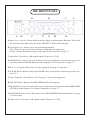
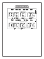
CONTENTS
INTRODUCTION
THE FRONT PANEL and SIGNAL FLOW
Input Selection
Input/Output Level Trims
Inserts 1-3 (SUM-DIFFERENCE processing)
Inserts 4, 5 (swap!)
Inserts 6-8
Mix/Fade Knob
THE BACK PANEL
THE GUTZ
Top Board
Bottom Board
INTERNAL TRIMS
SOME THOUGHTS FROM OUR LAB
TROUBLESHOOTING
SPECIFICATIONS
WARRANTY
WARRANTY REGISTRATION
APPENDIX 1 – EXAMPLE SETTINGS
APPENDIX 2 – TEMPLATE FOR STORING SETTINGS
INTRODUCTION
THANK YOU!…
…for purchasing the Manley Laboratories Mastering Insert Switcher. This product is the culmination
of many custom Manley mastering consoles and mastering processors. It all started back around 1990
when the only option for mastering houses was to commission custom pieces needed for their art. Several of the top mastering engineers approached us and requested audiophile grade consoles and special
mastering versions of our compressors and EQs. We were happy to listen and oblige - and frankly,
somebody had to support that neglected side of the business.
Over the next dozen years, mastering businesses flourished and branched, and many more audio
companies developed products aimed specifically for mastering. In fact, a whole new sub-category of
mastering grew out of this, most often called “project mastering”. Manley was getting deluged with
requests for custom projects at a point in time when it was difficult to keep up with orders for standard
products. We had to limit the number we could accept, and even those were beginning to take too long
to build and test, before we finally declined any new custom consoles. Meanwhile, several smaller
companies were beginning to market non-custom off-the-shelf mastering consoles (some remarkably
similar to Manley’s). This at least helped fill the void, which is why we did it in the first place.
However, even with several companies building reasonable mastering consoles, we were still getting requests for something similar; not custom, but “Manley, like the famous guys use.” The Manley
Laboratories Mastering Insert Switcher is one part of our solution. In fact, it represents an evolution in
performance from where we left off performing custom work.
The Manley Laboratories Mastering Insert Switcher is built with a unique electronic topology that
maintains a fully balanced signal path through 95% of the console. All other designs require the balanced signals to be converted to unbalanced before sections that, for example, allow you to boost or cut
level, then inversely need to be converted back to balanced to feed the outside world. In other words,
this new topology not only does it in one stage rather than 3 or 4, but also does it as cleanly and quietly
as any single stage that we know of, including fully discrete approaches. This topology also provides
better common mode rejection and power supply rejection than conventional approaches. This is significant especially in the “Sum-Difference” functions.
Each of the 10 gain blocks and all of the switches are on connectors, which means, if the need ever
arises for service, it can likely be done quickly without the need for a technician or soldering iron – just
a medium-small Philips screwdriver. No expense was spared in the quality of the parts, so one should
expect many years of continuous professional use.
Please note that this is not a “Monitor Control Box.” It is simply a device that helps route various
analog processors with maximum fidelity or allows you to maintain the shortest possible signal paths
while providing some flexible central control functions. This unit is not supposed to color your sound in
the least; it just exists to let you use your favorite outboard gear in more creative ways.
THE FRONT PANEL
A
B
D
C
F
E I
G
K
H
J
A. Input selector switches: Choose which of the three inputs to run through the Backbone. This switch
also determines what input comes out of the “SEL INPUT” XLR on the back panel.
B. Left-Right Reverse: Allows you to swap left and right channels.
Gains: When lit, bypasses all active electronics for the input and output gains.
Polarity: Changes the absolute polarity of the signal. For more on this, see page ???
C. Input Gains: 24-position, ½ dB stepped controls. From +6 to -5.5 dB.
D. SUM-DIF Rotary Switch: Lets you use Inserts 2 & 3 for sum-difference (mid-side) processing. Activated only when the SUM-DIF button (F in this diagram) is lit. For more info, see page ???
E. Inserts 1-8: Controls which inserts are in the signal path. See page ??? for details.
F. SUM-DIF Button: When lit, brings the SUM-DIF rotary switch into the circuit for processing of Inserts 2 & 3.
G. Swap: Swaps the order of Inserts 4 & 5. See page ??? for info and suggestions.
H. MIX-FADE Button: Brings in the MIX-FADE knob (I in this diagram)
I. MIX-FADE Knob: Acts as a master fader or mixer, depending on the position of the FADER MODE
SWITCH (J in this diagram). For a detailed explanation, see page ???
J. FADER MODE Switch: Selects the function of the MIX-FADE KNOB (I in this diagram). See page
??? for more info.
K. Output Gains: 24-position, ½ dB stepped controls. From +6 to -5.5 dB.
SIGNAL FLOW
The signal-flow through the console is simple enough to describe and mostly follows the front panel
left-to-right layout. Three pairs of XLRs on the back panel are balanced line inputs associated with the
client‘s source format. These could typically be a superb DAC (or two) and an analog tape machine.
INPUT SELECTION
Next come a pair of XLRs that are direct outputs of the chosen input. Typically these outputs would
feed a pair of monitor control box inputs and are used for comparing the raw tracks that were brought
in versus the effect of the mastering process. Mastering engineers may use this as a “confidence check”
and as an immediate way to show the client the “before and after pictures”. There are other outputs
that can be used to check the final output after processors, and for a mid-point in the processor chain if
desired.
The chosen input then can be Left-Right swapped just for those occasional sessions when either the
mixing studio accidentally swapped cables or the mix seems to sound better in the opposite perspective.
The mix can also be polarity flipped. This reverses the “phase” (polarity is the correct term) of both the
left and right channels. Probably one wants the kick drum pushing the speaker out rather than sucking
the speaker inward. Most of the time, “Polarity Reverse” is a subtle effect and with some mixes the effect is inaudible. Strangely, the effect is often most pronounced on reed instruments and some types of
vocal character. It is usually worth a quick check to verify which way seems to sound best and/or seems
to have the kick pushing the woofer outward. If in doubt, leave the polarity alone.
The Input Selection, Left-Right Swap and Polarity Reverse are accomplished purely passively, and
are highly unlikely to damage the signals at all. This is achieved with simple sealed gold-contact relay closures. In fact, the Left channel and Right channel signal paths are generally on separate circuit
boards and/or widely separated physically to maintain ideal channel separation and cross-talk. Where a
signal meets a connector, two gold contact pins and two wires are used for extreme reliability. That feature is called “redundancy” so that if one expects one failure in one thousand without, one might expect
one failure in a million, given redundancy (1,000 X 1,000).
INPUT LEVEL SWITCHES
Next up are the two INPUT LEVEL rotary switches that provide 24 precise ½ dB gain steps. The
range is from 6 dB of boost to -5.5 dB of attenuation. Ultra-low distortion thin film 0.1% tolerance
resistors are combined with sealed gold contact Greyhill switches. As described earlier, the gain stage is
that new-topology fully balanced circuit followed by a pair of unity gain high current buffers.
There is a BYPASS switch that removes all active electronics for both the INPUT LEVEL and
OUTPUT LEVEL control circuits. This is one more form of confidence check that allows you to compare whether two sets of gain stages have any hint of possible signal degradation. It also allows one to
run the console in a 100% passive mode.
Generally the INPUT and OUTPUT LEVELS are meant to correct for any losses or unintentional
gains from the source machines or in any of the outboard processing gear. However, these controls
really open a lot of possibilities in terms of driving gear hotter or softer especially when one considers
combining that concept with setting up outboard gain settings away from a standard unity gain setting.
The issue here is “the sweet spot” or “gain staging” and the fortunate or unfortunate aspect of many devices that just seem to sound best when driven a little harder or softer than the designer intended. One
can think of it a bit like a guitar amp with its input pot and master volume to get the right amount of
distortion at a comfortable stage volume. Or, one might be more familiar with analog mixing consoles
and liken it to finding that magic combination of individual fader levels and mix-bus fader level.
***In some cases, for “absolute purist fanatics”, even these buffers can be bypassed/removed
(by removing the chips and inserting small jumper wires between pins 3 and 8 on the dip socket)
for one less gain stage in the path – BUT in general they serve a number of beneficial purposes
(including isolating the cable and destination electronics from the gain stage’s feedback loop)
whereas buffer-ectomy may have more of an imaginary benefit . If you can’t hear any change of
quality bypassing ALL the electronics in the console (and so far that is the unanimous opinion),
then don’t even think of possible mods and variations (especially a mod that might be a detriment
in practice). Keep in mind, it also isn’t the kind of change that can be truly A-B compared…***
INSERTS 1-3…SUM-DIFFERENCE PROCESSING
OK, back to the idiosyncrasies of this Insert Box. Next in the signal path is INSERT #1. Pushing
the button marked INSERT 1 engages whatever box might be connected there. When the button is NOT
pushed and lit the main audio path is hard-wire bypassed, of course. However, a little isolation amplifier is engaged to feed that box. This is to pre-drive a compressor so that it is already doing appropriate
gain reduction at the moment that you do insert it. This prevents momentary level changes.
INSERT 2 and INSERT 3 are special. Below these button is another button labeled SUM-DIF
which engages a complete set of Sum / Difference encoders and decoders (or is it the other way
around?). Some people refer to this as M-S (or Mid-Side) but there are also those who insist that these
terms are reserved for mic techniques.
These circuits allow Insert 2 and 3 to act on both the mono (sum) and the side (difference) parts of
the original stereo signal. The left side becomes sum and the right side becomes the difference. So if
you just want to narrow the width of the extreme lows to help cut a lacquer, just cut lows on what was
the right channel of your outboard EQ and is now the “Difference Channel”. After passing through
Insert 2 and 3 the signals are decoded back to left and right. If the SUM-DIFF button is not in, Insert 2
& 3 just operate as the other inserts do, as normal stereo left and right.
There is also a 24 position switch that adjusts the level of the difference signal over a -5.5 dB (more
mono) to +6.0 dB (wider) range. Alternatively, one can mix the difference signal either treated or
untreated into the stereo mix near the end of the chain (more on that later). In other words, you should
have more than enough options to mangle the stereo image especially if you also have yet more sumdiff tools in your digital arsenal. Using it as a cheap trick to impress a client may have less desirable
consequences later. Just beware of mono compatibility and FM radio transmission issues, difficulties in
cutting vinyl records, diminished lead vocals, bass and drums in the mix (which might be more important to record sales) and reverb balances.
INSERTS 4 & 5…SWAP!
INSERT 4 and INSERT 5 are also special. You can reverse the order of these two using the button below marked SWAP. With the button pushed, Insert 5 precedes Insert 4. Whatever processors you
choose for these inserts, verify that with both units NOT bypassed and “flat” (e.g. zero compression),
that there are no unwanted effects related to the patch order, including other processors potentially in
the chain (especially Inserts 3 and 6 which are nearest 4 & 5).
It might be interesting to put compressor/limiters on these inserts. Depending on settings and the
order, there can be benefits in how each responds dynamically, especially if one unit tends to overshoot
a bit. Of course, the SWAP button will be appreciated by those who are tormented with the decision
of whether EQ should precede compression or vice versa. Usually, “it just depends.” With the gentle
processing typical in mastering, there isn’t much difference.
INSERTS 6-8
Next in the signal flow are INSERT 6 and INSERT 7, which are not special (like their neighbors
are, at least). Some engineers prefer these inserts for their main processors and some for their alternative or “occasional” processors. We know that was an ambiguous sentence, but what we mean is, use
these inserts for whatever you’d like to. We don’t mind either way.
INSERT 8 is special if for no other reason than being the last process in the chain. This, of course,
is likely the most appropriate place for your final limiter. The Manley Mastering SLAM! with the converter option can be highly advantageous here because even if it is followed by your favorite mastering
quality A to D converter, it gives you an superb alternative converter and a contender for a new favorite. We might suggest that this processor insert be used to sometimes push the level, after keeping the
signal at more reasonable and conventional levels earlier in the chain.
Between INSERT 7 and INSERT 8 is a multi-purpose function. Pushing the button labeled MIX
FADE below them engages the large Penny and Giles rotary knob to the right of INSERT 8. This is especially handy for “Producer Fades”. Most of the time, fades are simply done graphically in the workstation, but there are occasions when one wants a manual fade and big knob to ride the volume down
(or up). This rotary knob is called the...
MIX/FADE KNOB
There is a small toggle switch associated with this circuit that sets up alternative functions. With the
switch down, the FADER is a fader. Simple. With the switch in the middle, the knob becomes a precision stereo mixer. Lastly, in the “up” position, the mixer uses the “DIFF” signal from that earlier part of
the console so one can blend in a little extra width.
The basic MIX function is typically used for several purposes. One is the so-called “parallel compression” which generally employs a limiter set for somewhat drastic settings. When it is blended into
the main path, it has the effect of raising lower level signals without squashing transients, which sort of
translates to less quiet dynamics and increased ambiance. It can be considered a technique for manipulating quiet sections rather as opposed to normal limiting that affects the louder passages.
One could also try lightly mixing in extreme EQ or compression settings on the SUM or DIFF parts
of the signal, via the back panel XLRs. If you’re interested, more details on MIX/FADE techniques follow later on in the manual...
OUTPUT LEVEL SWITCHES
Right after the FADER/MIX stage is the final active stage, which are the OUTPUT LEVEL switches. Like the INPUT LEVEL switches, you have 24 ½ dB steps filling a -5.5 dB to +6dB range. And
this stage together with the INPUT LEVEL controls can be bypassed/engaged with the button marked
GAINS.
Now, it’s time for an...
*IMPORTANT PARAGRAPH*
Note that both the FADER/MIX and OUTPUT LEVEL controls precede INSERT 8. This way you
can patch your final limiter in 8 and semi-permanently set thresholds and gains, and use the OUTPUT
LEVEL controls as a very hand way to set how hard the signal is feeding the limiter and thusly how
many dB it is typically limiting. Sometimes this even negates the need for a special “mastering version”
limiter, because the most critical controls, threshold and output level, stay “calibrated” while the Mastering Switcher OUTPUT LEVEL controls become something like a “drive” or “input level” control.
THE BACK PANEL
*Note: The panel shown is for the Sub-D connections option. For the other configuration, connectors F, G and H are replaced with a pair of 56-pin ELCO connectors.
A
B
C
D
E
F
G
H
I
J
A. Power Switch: Where the IEC power cable is inserted, the fuse is placed, and the power is switched
off and on. Complex, yes, but most users should be familiar with this feature set.
B. Output L/R (x2): Two sets of balanced outputs, typically going to your favorite A/D converter and a
monitor controller/VU meters.
C. Mix Input L/R: These inputs feed the FADER in MIX mode. See page ??? for more details.
D. SUM-DIF Outputs: The outputs for the raw encoded signals (unprocessed by Inserts 2 & 3). SUM
signal is attenuated 6dB, DIF is boosted 6 db to bring them to “normal” levels that are easier to
process.
E. PATCHABLE Sends/Returns: Factory-wired to patch into Insert 6, but internally user-adjustable. See
page ??? for details.
F. Inserts 5-8 connectors: DB-25 (or 56-pin ELCO) connections for the last 4 inserts.
G. SUM-DIF jack: DB-9 connector for Sum/Difference input and output.
H. Inserts 1-4 connectors: DB-25 (or 56-pin ELCO) connections for the first 4 inserts.
I. SEL Input L/R: The selected input’s dry signal comes out here.
J. Inputs: 3 sets of inputs for whatever you want to plug into the Backbone. We recommend audio
sources; you can try plugging in your toaster, but it probably won’t sound very good.
BACK PANEL
As previously described, you have 3 Input XLRs per side followed by an Output XLR that reflects
the chosen input. These are factory set-up as AC coupled (the inputs are protected by capacitors, which
may prevent some clicks or pops when switching), which implies the signal has to flow through capacitors. If these capacitors are unwanted, there are jumpers (no soldering required) to bypass them and
provide DC coupled inputs (similar jumpers exist for the outputs). The diagram describing the jumper
locations is on page ???.
Next are Multi-Pin connectors that handle all of the INSERT inputs and outputs. One version of the
Mastering switcher uses EDAC/ELCO 56-pin connectors. These are very reliable and allow for pretty
bulky audiophile wires that many mastering engineers prefer. The other version uses 25-way sub-D
connectors, which are cheaper, easier to purchase pre-made, and semi-compatible with industry standard cable harnesses. The big difference between the industry standard and what the Mastering Switcher uses has to do with the XLR “sex”. The standard may have either all male or all female XLRs, while
what you need here is half male, half female. So, worst case scenario, buy one of each ‘standard’ cable,
and spend an hour or two swapping half of the XLRs (16). Better case scenario, buy a few pre-made
and tested from Manley, which use Mogami multi-pair. Best case scenario, have a good tech build some
audiophile wire (maybe silver conductor) cut-to-length, tailor-made ELCO cables. The pin-outs for
both the EDAC/ELCO and 25-way Sub-D connectors are on page ???.
Next comes an interesting pair of XLRs marked “PATCHABLE”. There are a number of points
internally in the console where these XLRs can be patched. Of course, this means opening up the Mastering Switcher, opening up the manual, attempting to interpret the map on page ???, and moving some
ribbon cables, but dealing with ribbon cables seems to be par for the course if you’ve had a PC in your
life. The three intended purposes for these are:
-An alternative to the multi-pins for one pair of inserts. You might use those for “producer-processors” or new gear you are evaluating. In that case, you probably don’t want to have anything
plugged into the corresponding XLRs off the multipins. For example, the Manley factory presets
that “PATCHABLE” to INSERT 6, so use either the multi-pin Insert 6 XLRs or these. Actually, just
watch out for the female XLRs or inputs because you don’t want the outputs from two different
boxes feeding into each other. The alternative set of male XLRs can be considered a parallel output,
so it can feed something. Which brings us to…
-A feed to the monitor controller for checking the processing half-way into the chain. Typically
a mastering engineer may want to compare the dry signal (“Selected Input” XLR), the analog
processed signal (Main Output 2), and maybe somewhere part way through the processing, which
these jacks allow.
-A feed for some of those unusual processing tricks described in the FADER/MIX section on
page ???.
Next on the back panel are outputs for SUM and DIFF. These are the raw encoded signals (unprocessed by Insert 2 & 3). These XLRs could be used to send to processors, in which case probably either
but not both would be used. You can also send these signals to VU meters. **Note that the SUM signal
is attenuated 6 dB and the DIFF signal is boosted 6 dB, so that with typical stereo music mixes these
outputs have similar levels as the left and right signals (easier to process).**
After that, you get MIX INPUTS. These feed the FADER in MIX mode. As described on page ???,
if you use these as a return from processing the DIFF signal (but not the SUM), you should get a special Y cable where the right XLR is wired out-of-phase.
Last is a pair of stereo outputs. One pair generally goes to your main Analog to Digital Converter
and the other goes to the monitor controller or VU meters.
THE GUTZ
GUTZ
There is a 4-deck sandwich arrangement of printed circuit boards that make up the active electronics that process audio. Two long boards are so-called motherboards that hold 5 small PCBs each. There
are separate motherboards for left and right, and the left is the top board, while the bottom takes care
of the right. Each mother has about 36 relays and a dozen connectors, plus about 4 ICs that feed a fake
signal to bypassed inserts. There are a number of connectors on the bottom the motherboards to join
with each other.
The 5 small daughter boards on each mother can be considered gain blocks and there are 10 total.
Each is labeled to its calibrated location but there is some minor inter-changeability for troubleshooting. For example, on each mother, #1 and #5 (INPUT TRIM, OUTPUT TRIM) can be swapped and
similarly #2 and #3 (SUM-DIFF encode, decode). However, one cannot swap daughter boards from
the bottom to the top mothers because of connector inversions. Because of the precision calibrations,
especially in the SUM-DIFF circuits, we advise that after a temporary swap the boards should go back
to their original locations.
If one board or switch develops a problem and needs to be replaced, Manley has a support program
and boards in stock intended for swapping in the field (rather than sending the entire Mastering Switcher back to the factory and losing time).
Each daughter board has several trimmers and some of them should be tweaked on a routine basis
(like once a year) for best performance. These would be trims associated with gains and DC offset.
About half the trims may rarely need tweaking or perhaps can be left at factory settings and these are
only associated with common mode rejection (hum & buzz immunity). There is an complete trimmer
adjustment procedure on page ???.
Similarly, front panel boards associated with EAO buttons (which are also on sockets) and Greyhill
switches, back panel boards associated with XLRs and multi-pin connectors and power supply boards
are all on connectors and can be easily field serviced. The Mastering switcher should be operable for
decades.
GUTZ cont’d: TOP WIRES
GUTZ cont’d: BOTTOM WIRES
INTERNAL TRIMS
SOME THOUGHTS
FROM OUR LAB
GEAR SEQUENCE
Another interesting quality of much analog gear is the optimum sequence of gear. While there is
some validity to ideas of “EQ before compression” or “EQ after compression”, the practical reality
is trickier. For example, Box #1 may seem to sound best only if it drives into another box that does
not have a transformer input – it likes to see a relatively simple load and maybe really shines driving
into just one particular box for unknown reasons. Box #2 may be quite the opposite, and it just loves
to drive a transformer input. So the optimum order may just take a day or two of experimentation and
listening, rather than thinking about the function of the box. This is the biggest single reason for not
including the option which allows one to arbitrarily change the order of processors – there is almost
always an optimum order sound-wise and we want to encourage you to find that and get the elusive and
maybe mysterious optimum path, rather than promote mastering as “simple fun with expensive toys”.
While we are on that topic, there are some other interesting and not very obvious potential sequences of processors. For example, engineers might only consider a brick-wall limiter as appropriate as a
final or next-to-final process. And while that is generally a good place for one, you might find that a
limiter early in the chain helps compressors and de-essers further down from over-reacting and pumping, and might prevent EQs from clipping. We are not suggesting trying it for the sake of an idea, but
suggesting a listening experiment because, in the end, it is more about the particular collection of gear
that you have chosen and the collection of input-output idiosyncrasies that few are aware of. This hints
at why some people hate gear that others love. The “sound” of a processor has to do with what device is
patched to what, and settings of input and output levels. One might hear serious raves about some piece
and expect something dramatic, when it was actually the subtlety of the box that was so sweet, so one’s
expectations play a part in user reviews. And not everybody has the same goals, styles and requirements.
SOME SUM-DIFFERENCE MUSINGS
One school of thought suggests we use our gentlest and smoothest processors for mid-side tweaks,
mostly because there can be inherent dangers with moderate alterations of those channels. But this is
mastering, and a few dB of this or that is already verging on drastic, right? The other school of thought
suggests that sometimes a narrow notch or steep filter on either the sum or difference can effectively
treat problems that can’t be fixed any other way. Perhaps you will find that these two inserts are better
served with your best EQ’s than with dynamic processors. Equalizing in the sum-diff domain relaxes
some of the demands of precise left-right matching.
“WIDTH”
We’ve just talked about how subtle SUM-DIFF processing can be very useful. With that said, be
very careful not to mangle the stereo image too much - this is a tool that is often over-used, abused, and
very poorly understood. Certainly you have heard speakers wired out-of-phase and heard a stereo pair
and checked out what happens if one side is phase-reversed. It is not pleasant and can be rather disconcerting. Increasing the stereo width is employing the same effect but to a lesser degree.
“WIDTH” cont’d...
So we’ve all heard some “big” sounds before that result from mid-side tweaks. But did you know
this? Let’s say you increase the width by just 1 dB (which is pretty subtle). What begins with maybe
100 dB dB of separation between left and right diminishes quickly. Now a sound that was panned hard
left will also be on the right side but out-of-phase and down about -20 dB. So, what seems only a hair
wider actually reduced left-right separation from 100 dB to 20 dB. Maybe this could be a concern if
you expect some people will listen on headphones. Maybe mixes with cool dramatic hard panned tracks
might actually LOSE some width along with losing center. Hmmm.
To do what we want, an analog circuit requires that 2 signals get subtracted (and added) accurately,
and this happens twice. It relates to a common spec called “common mode rejection ratio” or CMRR.
In general, good CMRR is spec’d for a low frequency because the numbers are best there and get
worse as the frequency gets higher. For example, a typical op-amp like a MC5534 can claim a best case
scenario CMRR of 90 dB at 60 Hz. Looking at the graph, however, that number drops to 40 dB at 20
kHz. Not very impressive, if we hope for 80 dB across the entire spectrum as a base-line. A typical high
quality resistor may have a tolerance rating of 1% which means it is likely we only get 40 dB of separation in practice. Even a superb resistor might be 0.1% tolerance which translates to 60 dB. So to make a
long story short, it ain’t easy to get 80 dB of separation from 20 to 20K in a high performance sum-diff
and back circuit in analog. It is easy in digital when the operations are just a few additions and subtractions, and 24 bit math virtually guarantees numbers in the range of 144 dB. But these are just numbers
and the previous paragraph suggests that once one actually adjusts or processes sum-diff signals those
numbers become low quickly anyways.
Perhaps some of the feeling that increasing the width is practically necessary in mastering might
be due to a few common modern studio techniques that may accidentally strip some subtle localization
cues. For example, the ear uses the initial onset of transient peaks as well as phase and level differences
as localization cues, and now we have more dynamic processors (compressor plug-ins on every track,
group and mix bus) in more studios than ever before in history. We also have more tracks and denser
arrangements. We time shift tracks and use more high-pass filters (messing with phase). Not that these
things are bad, but one should be aware that there are always trade-offs, and some say that “Engineering is the art of balancing trade-offs”.
MORE ON THE MIX/FADE KNOB
Traditionally, mastering engineers used a mix function when cross-fades between two analog tape
machines were used to segue between songs. Now that is much easier done in the workstation. But
in recent years, with the availability of convolution reverb programs and sizable libraries of impulse
responses (IRs) on the internet, some mastering engineers are finding that a touch of convolution reverb
helps gel dryer mixes. The effect should not be like “reverb” in the traditional sense but more like a
naturally complex flavor. Not surprisingly, the most likely IR candidates are fast decaying real rooms
somewhat on the “dry” side. The bad news is that it can be unpredictable, which IR works best with
each session or even each song, and auditioning IRs can be time-consuming and tedious. In any event,
it is a dangerous technique and one to be used sparingly and subtly, unless the client requests to put reverb on a whole mix. But there are plenty of free “colors” to add to your palette if you have the inclination to experiment on your own time.
There are other possible sources you may want to try. For example, both the sum and difference
signals appear on the back panel XLRs and you may find that you can do some really dramatic equalization or compression on either of those and mix it lightly back into the stereo mix, similarly to what
was described in the “Sum-Difference Musings” section earlier. You would need a special XLR “Y”
cable to do this right. This cable would start with a female XLR, with two balanced lines coming out
of it to two male XLRs. Very important note: One male XLR gets wired conventionally and the other
male XLR needs to be wired reverse phase and that XLR should get boldly marked “RIGHT”. There is
a diagram of this cable on page ???.
Another possibility is introducing a processor that might ordinarily be considered too colored or
distorted for mastering but if mixed in lightly (as opposed to running the full signal through it), can be
brought in under the main signal. This technique may tend to vary dynamically depending on the nature
and depth of the distortion. For example, if it is set up to be a conventional clipping effect, during quiet
passages, there may be no clipping, during moderate levels where there is some clipping, the mixed-in
effect might seem significant. However, with even hotter passages, the clipping is preventing that effect
from gaining more output level, while the dry signal has had no such restraint, so the relative mix will
lean more toward dry. Pre-limiting that color-box can prevent the distortion from becoming too nasty.
Yet another combination that can be excellently mixed in is the limiter-EQ, where you have the
EQ set for drastic high boost or drastic “smiley face” boosted low & highs & dipped mids. What happens is that as the signal level drops, with this low threshold limiter-EQ, the proportion of “wet” signal
becomes relatively stronger. In the first case, it would give more highs and air at low levels without becoming harsh and biting once the song gets loud. The second case acts a bit like an automatic FletcherMunson EQ where both highs and lows seem bigger at lower levels (opposite of what our ears normally
do, so it sort of “compensates”) and this happens without the usual drawbacks of just boosting lows and
highs. It is probably best to have the limiter set up to be digging in at relatively lower levels, which is
quite the opposite of typical limiter settings. Note, that normal transients are passed by the “dry” part of
the chain. Also, these kinds of tricks can bring a new motivation for keeping gear that may have been
collecting dust, because it doesn’t require the ultra-high performance that you need for the primary
chain.
MAINS CONNECTIONS
Your BACKBONE has been factory set to the correct mains voltage for your country. The
voltage setting is marked on the serial badge, located on the rear panel. Check that this complies
with your local supply.
Export units for certain markets have a moulded mains plug fitted to comply with local requirements. If your unit does not have a plug fitted the coloured wires should be connected to
the appropriate plug terminals in accordance with the following code:
GREEN/YELLOW
BLUE
BROWN
EARTH
NEUTRAL
LIVE
As the colours of the wires in the mains lead may not correspond with the coloured marking
identifying the terminals in your plug proceed as follows:
The wire which is coloured GREEN/YELLOW must be connected to the terminal in the plug
which is marked by the letter E or by the safety earth symbol or coloured GREEN or GREEN
and YELLOW.
The wire which is coloured BLUE must be connected to the terminal in the plug which is
marked by the letter N or coloured BLACK.
The wire which is coloured BROWN must be connected to the terminal in the plug which is
marked by the letter L or coloured RED.
DO NOT CONNECT/SWITCH ON THE MAINS SUPPLY UNTIL ALL OTHER
CONNECTIONS HAVE BEEN MADE.
Note: This unit has been factory wired for your country. If you plan to take the unit to
countries with a different mains voltage you will need to send the Backbone to Manley Labs
for the correct wiring conversion - or use AC voltage converters.
WARRANTY
All Manley Laboratories equipment is covered by a limited warranty against defects in materials and workmanship
for a period of 90 days from date of purchase to the original purchaser only. A further optional limited 5 year transferrable warranty is available upon proper registration of ownership within 30 days of date of first purchase.
Proper registration is made by filling out and returning to the factory the warranty card attached to this general warranty statement, along with a copy of the original sales receipt as proof of the original date of purchase, or registration can be made online in the Tech Support section of www.manleylabs.com.
This warranty is provided by the dealer where the unit was purchased, and by Manley Laboratories, Inc. Under the
terms of the warranty defective parts will be repaired or replaced without charge, excepting the cost of tubes. Vacuum tubes and meter or badge lamps are warranted for six months provided the warranty registration is completed as
outlined above.
If a Manley Laboratories product fails to meet the above warranty, then the purchaser’s sole remedy shall be to first
obtain a Repair Authorization from Manley Laboratories and return the product to Manley Laboratories, where the
defect will be repaired without charge for parts and labour. All returns to the factory must be in the original packing, accompanied by the Repair Authorisation, and must be shipped to Manley Laboratories via insured freight at the
customer’s own expense. Factory original packaging can be ordered from Manley Labs. Customer will be charged
for new factory original packaging if customer fails to ship product to Manley Labs in the original factory packaging. After repair, the product will then be returned to customer via prepaid, insured freight, method and carrier to be
determined solely by Manley Laboratories. Manley Laboratories will not pay for express or overnight freight service
nor will Manley Laboratories pay for shipments to locations outside the USA. Charges for unauthorized service and
transportation costs are not reimbursable under this warranty, and all warrantees, express or implied, become null
and void where the product has been damaged by misuse, accident, neglect, modification, tampering or unauthorized
alteration by anyone other than Manley Laboratories.
The warrantor assumes no liability for property damage or any other incidental or consequental damage whatsoever
which may result from failure of this product. Any and all warrantees of merchantability and fitness implied by law
are limited to the duration of the expressed warranty. All warrantees apply only to Manley Laboratories products
purchased and used in the USA. All warrantees apply only to Manley Laboratories products originally purchased
from an authorized Manley dealer. Warranties for Manley Laboratories products purchased outside the USA will be
covered by the Manley Importer for that specific country or region. “Grey Market” purchases are not covered by
an warranty. In the case that a Manley Laboratories product must be returned to the factory from outside the USA,
customer shall adhere to specific shipping, customs, and commercial invoicing instructions given with the Return
Authorization as Manley Laboratories will not be responsible for transportation costs or customs fees related to any
importation or re-exportation charges whatsoever. Some states do not allow limitations on how long an implied warranty lasts, so the above limitations may not apply to you. Some states do not allow the exclusion or limitation of
incidental or consequential damages, so the above exclusion may not apply to you. This warranty gives you specific
legal rights and you may also have other rights which vary from state to state.
For Tech Support and Repair Authorization, please contact:
MANLEY LABORATORIES, INC.
13880 MAGNOLIA AVE.
CHINO, CA. 91710 USA
TEL: (909) 627-4256
FAX: (909) 628-2482
email: [email protected]
WARRANTY REGISTRATION
We ask, grovel and beg that you please fill out this registration form and send the bottom half to:
MANLEY LABORATORIES
REGISTRATION DEPARTMENT
13880 MAGNOLIA AVE.
CHINO, CA 91710 USA
OR you may FAX this form in to: +1 (909) 628-2482 OR you may fill in the online warranty
registration form found in the Tech Support section of our website (www.manleylabs.com) OR you can
be really diligent and register your warranty three times to see if we get confused!
Registration entitles you to product support, full warranty benefits, and notice of product
enhancements and upgrades, even though it doesn’t necessarily mean that you will get them (just
kidding!) You MUST complete and return the following to validate your warranty and registration.
Thank you again for choosing Manley gear and reading all the way through The Owner’s Manual.
(We really mean that sincerely, the bit about thanking you for choosing our gear. THANK YOU!!!)
MODEL _______________________ SERIAL #_______________________________
PURCHASE DATE ______________ SUPPLIER ______________________________
----------------------------------------------------------------------------------------------------------PLEASE DETACH THIS PORTION AND SEND IT TO MANLEY LABORATORIES
MODEL _______________________ SERIAL #_______________________________
PURCHASE DATE ______________ SUPPLIER ______________________________
NAME OF OWNER ______________________________________________________
ADDRESS _____________________________________________________________
CITY, STATE, ZIP _______________________________________________________
EMAIL ________________________________________________________________
TELEPHONE NUMBER__________________________________________________
COMMENTS OR SUGGESTIONS?_________________________________________
_______________________________________________________________________
Notes:
EXAMPLE SETTINGS