1
HIGH CURRENT
POWER AMPLIFIER
GFA-555ms
The contents of this manual are subject to change. Please check our website
www.ADCOM.com or www.ADCOM-USA.com for the most current version.
Copyright © 2011 ADCOM LLC
Rev 2.1
INTRODUCTION
Please read thoroughly these operating instructions for the GFA-555ms before connecting
or attempting to operate it. The installation and operation of the GFA-555ms are described in
the following pages. We sincerely hope you will value and enjoy the considerable attention
we have given its design and construction. This manual has been written to help you
understand the correct operation of the GFA-555ms. Please read it carefully to fully
comprehend all its features and functions and thereby derive maximum performance from its
use in your system. It is a good idea to keep this manual handy for future reference.
PREFACE
WARNING
The GFA-555ms is a very powerful amplifier capable of delivering very large peaks into low
impedances, exceeding 80 amperes per channel. Therefore, be certain to exercise
extreme caution when making connections to and from the amplifier. Always make certain
that the amplifier is disconnected from the AC outlet, and its large filter capacitors
are discharged. Please note that the power supply capacitors can take more than five
minutes to discharge. Failure to observe this precaution may result in damage to the
loudspeakers and/or blowing of the amplifier's DC RAIL FUSES, conditions which are
NOT covered by the warranty.
The GFA-555ms amplifier can drive a very broad range of loudspeakers. including those
with very low impedances, at sustained high-power levels, even when the impedances are
highly reactive. Great care was taken to insure that distortion in the amplifier would remain
extremely low, particularly when driving these highly reactive loads in which the phase
angles of the voltage and the current are substantially different. A little known fact is that
amplifiers which measure extremely well on the test bench into a resistive load may not
develop the same amount of power into a loudspeaker. Depending on the amplifier's design,
sometimes as little as one third of the power which the amplifier develops into a resistor is
delivered to a speaker load. Also, the distortion level measured when the amplifier is driving
a resistive load is degraded. in some cases quite substantially, when driving the loudspeaker.
It is, however, very difficult to measure the performance of an amplifier into a loudspeaker.
One reason why this information is not widely known is because during such high-power
tests, destruction of the loudspeaker is often the result. In order to determine the
performance of the GFA-555ms, ADCOM developed a "computer model" of a "difficult"
loudspeaker load. A computer model "mimics" the reactance of the very difficult speaker and
duplicates the actual phase angles of the voltage and current throughout the entire audio
range. In this manner, high-power testing of amplifier parameters could be undertaken
without repetitive destruction of the loudspeaker load.
To achieve the above, eight sets of specially selected TO-3-type, metal-cased bipolar output
transistors are used in the GFA-555ms in a triple-Darlington configuration of its driver and
output stages. The safe operating area of these transistors, along with their circuit topology,
insures very efficient power delivery to reactive loads, regardless of the phase angle of
voltage and current. In addition, no protection or current-limiting circuitry is used in the
GFA-555ms which could degrade the Signal.
Electronic protection, or current-limiting circuitry, would impede the delivery of large amounts
of current (power) to low-impedance, highly reactive loads, thereby constricting dynamics
and deteriorating sonically the performance of the amplifier. Therefore, only fuses on the DC
rails are used for protection.
The power supply in the GFA-555ms has enormous reserve power capability with an
extremely large transformer feeding a storage bank of 40,000uF of filter capacitance. The
transformer itself was designed for extremely good regulation, insuring stable voltages
regardless of the power demands from the amplifier. Its higher efficiency was insured by
using a toroidal design. Additionally, thermal and dynamic tracking of the bias for the
triple-Darlington driver and output stages is provided to insure that the amplifier operates in
its optimal range regardless of the length of time and the level of operation.
The GFA-555ms's circuitry is direct-coupled internally to minimize the sonic deterioration
which capacitors, when used between stages of amplification, can cause. As a result, the
GFA-555ms can amplify DC and has no limit as to low-frequency or peak-bass energy
delivery. In particular, the driver stages are designed to provide all the current required by
the output devices without limiting, compressing, or otherwise distorting the signal coming
into the power amplifier.
All internal point-to-point wiring is OFC and the highest-grade parts, consistent with their
application and voltage requirement, have been used in its construction. In especially critical
circuits, the finest quality film capacitors have been used. Among its other design
improvements are the following:
Larger potted transformer provides better overall regulation for driving lower
impedances at high power levels; also provides greater peak-current capability into
loudspeaker loads.
No electrolytic capacitors in the low-frequency signal path or feedback-loop path. Only
precision non-polarized capacitors are used.
Addition of a servo circuit minimizes DC-offset voltage at the loudspeaker outputs; this
insures that there is no woofer "biasing" with attendant low-frequency distortion.
Larger heatsinks for each channel for greater heat dissipation and better temperature
and dynamic bias tracking. Greater thermal stability is thereby insured.
More cooling vents on top cover and chassis for greater cooling efficiency and cooler
operation into lower impedances.
High-quality, gold-plated brass RCA input jacks with Teflon insulators.
Thermal overload indicator LED on front panel.
IMPORTANT NOTICE
ADCOM PROTECTION PLAN
(U.S.A ONLY)
ADCOM offers the enclosed valuable Limited Warranty. Please read the details on the
Warranty card carefully to understand the extent of the protection offered by the Warranty,
its reasonable limitations, and what you should do in order to obtain its benefits. Please
register your warranty online at www.ADCOM.com or www.ADCOM-USA.com
Be sure to verify that the serial number printed on the rear panel matches the serial number
on the outer carton. If any number is altered or missing, you should notify us immediately in
order to insure that you have received a genuine ADCOM product which has not been
opened, mishandled or tampered with in any way.
UNPACKING
Before your GFA-555ms left our plant, it was carefully inspected for physical imperfections
and tested for all electrical performance parameters as a routine part of ADCOM's
systematic Quality Control. This, along with full operational and mechanical testing, should
insure a product flawless in both appearance and performance. After you have unpacked
the GFA-555ms, inspect it for physical damage. Save the shipping carton and all internal
packing materials, as they are intended to reduce to a minimum the possibility of
transportation damage, should the amplifier ever need to be shipped again. In the unlikely
event damage has occurred, notify your dealer immediately and request the name of the
carrier so that a written claim to cover shipping damages can be initiated.
THE RIGHT TO A CLAIM AGAINST A PUBLIC CARRIER CAN BE FORFEITED IF THE
CARRIER IS NOT NOTIFIED PROMPTLY IN WRITING AND IF THE SHIPPING CARTON
AND PACKING MATERIALS ARE NOT AVAILABLE FOR INSPECTION BY THE CARRIER.
SAVE ALL PACKING MATERIALS UNTIL THE CLAIM HAS BEEN SETTLED.
INSTALLING THE GFA-555ms
The GFA-555ms is equipped with large heatsinks to dissipate the heat generated by the
output power transistors. Although during normal home operation the heatsinks will become
just warm to the touch, there are instances during high-level playback into low impedance
speakers which will cause the heatsinks to become much warmer than normal. Therefore,
adequate air circulation MUST be made available to ensure proper heat dissipation
from the heatsinks. You will ensure the amplifier's long-term, trouble-free operation if you
keep it away from external sources of heat, such as radiators, hot-air ducts or intense direct
sunlight, and provide reasonable ventilation. The GFA-555ms should never be placed with
other heat-producing components in a cabinet or enclosure lacking free air flow. You should
also provide adequate space around the amplifier to insure good air circulation.
The top, bottom and side panels of the amplifier have been provided with slots to allow
necessary cooling of the internal components of the amplifier. This GFA-555ms Required
Four Inches of Clearance on the Top and All Sides. You should ensure that these slots
are not obstructed in any way.
We advise that you refrain from stacking other components on top of the GFA-555ms. Not
only will the heat generated by the amplifier affect the performance of equipment stacked on
top of the GFA-555ms, but the free flow of air through the ventilating slots provided in the
chassis of the amplifier may be partially obstructed. If you require that the GFA-555ms be
mounted in an enclosed cabinet, it is recommended that the rear panel of the cabinet be
provided with vents or slots at the bottom and top to allow air to circulate freely through the
cabinet.
If you observe these recommendations, the GFA-555ms will perform quite reliably in any
reasonable environment. You should also pay attention to such routine considerations as
protection from excessive dust and moisture. Occasional vacuuming of accumulated dust on
the surfaces of the chassis, panels and heatsinks should be all that is required.
For use in professional installations, the GFA-555ms may be mounted in a standard 19-inch
rack using the optional RM-7 rack-mount adaptors available through ADCOM dealers. If the
GFA-555ms is to be mounted on a rack, along with other components which are
interconnected to the GFA-555ms, the amplifier's chassis must be insulated from the
metal-rack rails to prevent ground loops, especially if the rack is grounded to "earth", and to
avoid defeating the audio grounding scheme of the power amplifier (the audio-input grounds
are isolated from and above the chassis ground). Please consult the instruction sheet
packed with the optional rack-mount adaptors for more information.
CONNECTING THE GFA-555ms
The optimal performance of the GFA-555ms will ultimately depend on the care with which
you perform the connections to the amplifier, the preamplifier and the loudspeakers. All the
input- and output-signal connections should be made only with high-quality, low-loss cables
following the recommendations made in the individual sections below. Please refer to the
rear-panel diagram to identify all the connections and their locations.
NOTE
WHENEVER CONNECTIONS TO OR FROM THE GFA-555ms ARE BEING MADE, BE
CERTAIN THAT THE POWER SWITCH ON THE AMPLIFIER IS IN ITS OFF POSITION,
THE AC LINE CORD OF THE AMPLIFIER IS DISCONNECTED FROM THE AC WALL
OUTLET AND THAT ALL ASSOCIATED COMPONENTS ARE TURNED OFF.
RIGHT/LEFT INPUT
The audio inputs to the GFA-555ms are through two high-quality, gold-plated brass RCA
jacks using Teflon insulation to minimize high-frequency losses, noise, etc. They will accept
standard RCA-type plugs, one for each channel, LEFT and RIGHT, usually supplied at the
ends of interconnecting cables. To insure that the performance designed into the
GFA-555ms is preserved, you should use the highest quality plugs and cable as are feasible.
There are many cables which are designed specifically for these applications and your
ADCOM dealer can be of help in selecting the best cable for your application. Whatever
cable you finally select, it should have low capacitance. This is particularly important if you
use a long run between the preamplifier and the amplifier or if your preamplifier has a high
output impedance. Generally speaking, a cable with a capacitance of around 100pF will
work well.
The load impedance which the GFA-555ms inputs present to the source preamplifier is
100,000 ohms. This load impedance results in minimal amplifier noise and is more than
adequate for use with any associated source component regardless of its output impedance.
To preserve the correct stereophonic effects, please be certain to connect the left output of
the preamplifier to the RCA jack on the GFA-555ms labeled LEFT INPUT and the right
output of the preamplifier section to the RCA jack labeled RIGHT INPUT.
RIGHT/LEFT STEREEO SPEAKER OUTPUTS
The GFA-555ms's connections to the loudspeakers are made through high-grade 5-way,
gold-plated brass binding-post terminals located on the rear panel. These terminals will
accommodate either bare wire, tinned wire, terminal pins, spade lugs, or "banana plugs",
both single and dual. The output terminals are color-coded RED and BLACK to indicate
polarity. To insure correct stereo phasing, you must connect the RED output terminal
(labeled "+") to the loudspeaker input terminal color-coded RED (or labeled POSITIVE, "+",
POS,8OHMS or 4 OHMS). The BLACK binding post terminal on the amplifier (labeled "-")
should be connected to the BLACK loudspeaker terminal (or labeled NEG, "-", C, COM,
COMMON, G, or GROUND).
NOTE
The GFA-555ms is polarity correct; that is, it does not invert "phase". Any positive-going
signal at its inputs will appear as a positive-going signal at its outputs.
The RIGHT STEREO OUTPUT should be connected to the right-channel loudspeaker, as
you face the pair of loudspeakers, and the LEFT STEREO OUTPUT to the left-channel
loudspeaker.
Be certain, when the GFA-555ms is used in Its stereophonic mode, the
STEREO/BRIDGED MONO INPUT switch is in the STEREO position. Otherwise, the
amplifier will not operate in the stereo mode. You will amplify only the left channel through
both outputs of the amplifier. For further clarification, please refer to the section
STEREO/BRIDGED MONO INPUT/OUTPUT.
In order to insure that connections to the loudspeakers are correct, you must be able to
identify each wire conductor of the loudspeaker cables at both ends of the cables. This is
relatively easy to do since most loudspeaker cables consist of two parallel, stranded
conductors in a flexible insulation, with a coding system for wire identification. Sometimes
there is a colored "tracer" wrapped around one of the conductors; some cords have one of
the conductors colored silver and the other copper; some have a "ridge" molded on the
insulation on one of the conductors, while others are marked with a "+" and/or "_". Your
ADCOM dealer also sells special loudspeaker interconnecting cables and these are most
often labeled with respect to polarity.
Generally speaking, when making connections to the loudspeakers from the amplifier, it is
very important to use the correct type and size of wire in order to avoid unnecessary loss of
amplifier power in the cable, reduction of amplifier damping factor (DF) and other
undesirable conditions. For runs up to 12 feet, ordinary "zip" or lamp cord, made of AWG18
stranded wire and available in a variety of insulation colors may be used. For runs up to 40
feet, AWG16 stranded wire should be used to prevent power losses. For lengths over 40 feet
and not exceeding 60 feet, useAWG14stranded wire only. Runs exceeding 60 feet require
the use of heavier conductors such asAWG12stranded wire. If you find it difficult to obtain
the correct-size wire for your specific connecting length, you can parallel two runs of the next
smaller gauge of wire to keep wire resistance at a minimum. For example, if you require a
run of 35 feet to your loudspeakers and AWG16 wire is not readily available, you can parallel
two 35-foot lengths of identical AWG18 stranded wire for use with each speaker (you'll
require a total of four 35-foot lengths in such an instance) and solder the two conductors of
each wire making up each double cable, at both the speaker and amplifier ends, to insure
good electrical and mechanical connections of the conductors.
Regardless of the cables you select to connect your loudspeakers, there are some other
requirements which you should observe in order to insure maximum performance from your
amplifier. It is most important that you make certain the wiring you have selected has as
Iowa capacitance as possible. All amplifiers, particularly wide-bandwidth audio amplifiers,
are susceptible to the capacitance cables present to their outputs at extremely high
frequencies. This capacitance, in conjunction with the inductance of the wire itself and the
reactive load of the loudspeakers, can create anomalies at ultrasonic frequencies which,
although inaudible, can affect performance in the audible range.
There are different ways to connect the wiring to the RIGHT/LEFT STEREO SPEAKER
OUTPUTS. The methods used will depend on the specific type of connectors supplied with
the loudspeakers, the speaker cables, etc. As a matter of course, we prefer to use double
banana plugs because it is generally the most secure method of connection. Also, the
plated-bronze springs of the banana plugs effect a self-cleaning action which insures the
best contacts between the binding posts and the connectors themselves. There are
"sockets" provided in the center of the binding posts' studs which permit secure seating of
the banana plugs. Make certain, however, that the hexagonal head of the binding post is
securely tightened before inserting the banana plugs firmly into the binding posts' sockets.
Additionally, when connecting the cables to the amplifier and loudspeakers, it is important
that you "tin" the wires with good solder (preferably high-silver-content solder) in order to
minimize contact resistance. Tinning prevents the build-up of surface compounds which
form with copper wire and which increase its contact resistance. It is partly for this reason
that double or single banana plugs are preferred. However, make sure that the cable ends
are tinned before you make the cable connections to the banana plugs. Alternatively, you
can use "crimped" pins or other lugs to insure lowest contact resistance at the connection to
the amplifier and loudspeakers.
If you prefer to use other methods of connection, unscrew the insulated, hexagonal head of
the binding post until the hole in the binding-post stud is accessible. You can then insert the
bare or tinned wire, or terminal pin, through the hole. You can also use the many varieties of
spade lugs available by simply placing the tines of the spade lug onto the binding post stud.
Turn the insulated hex head of the binding post clockwise until the wire or connector is firmly
secured. Finger pressure is sufficient and you should not use pliers, or other tools, which
could damage or over-tighten the binding post assembly. The binding post has been
designed in such a way that finger pressure is all that is needed to cause a "pinching" action
among the different metal surfaces to insure proper connection.
All loudspeaker systems having a nominal impedance down to 2 ohms can be connected to,
and driven by, the GFA-555ms. The GFA-555ms can drive these low impedances at more
than adequate power levels with no difficulty. It should be noted here that many loudspeaker
systems which are rated, nominally, at 4 ohms drop in impedance, in some parts of their
frequency range, to as low as 2 ohms (and some others to even less than 2 ohms). You will
not experience difficulties even with these very-low-impedance loads.
In most applications, you can drive two or more sets of loudspeakers. You should note,
however, that when loudspeakers are paralleled, the impedance presented to the amplifier is
lower than the nominal impedance of each loudspeaker. In other words, if you parallel two
8-ohm sets of loudspeakers, the resultant impedance will be 4 ohms. If you parallel two sets
of 4-ohm-impedance loudspeakers, the resultant impedance of the load will be 2 ohms. If
8-ohm and 4-ohm loudspeakers are paralleled, the resultant impedance will be about 2.6
ohms. In these last two situations, and depending on the lowest impedance of the
nominally-4-ohm speakers, and when making excessive power demands from the amplifier,
you may trigger the THERMAL PROTECTION on the amplifier or blow one of the DC RAIL
FUSES. See their respective sections for more information. In those very rare instances in
which your particular application causes frequent activation of the THERMAL PROTECTION
e circuitry, you might consider use of an auxiliary fan to increase amplifier cooling.
Alternatively, and for convenient switching of multiple sets of speakers with impedance
protection for the amplifier, you may consider the use of an ADCOM speaker selector. These
are available from your ADCOM dealer.
Should you wish to verify that your loudspeakers are in-phase, once connections to the
amplifier have been made, play a recording of solo voice with single-instrument
accompaniment, at normal volume, with the preamplifier's mode switch in the mono or A+B
position. Stand about three feet in front of the loudspeakers and exactly between them. If
your loudspeakers are in-phase, the voice and accompanying instrument will appear to
originate from a point directly in front of you and exact localization will be fairly easy. If you
now move a foot or two to the left and the right of your previous position, the singer and
instrumentalist will still appear to come from a point directly in front of you. If your
loudspeakers are out-of-phase, the image of the performers will be imprecise and difficult to
pinpoint. Depending on the room, the image may appear to be coming from behind you, or
the sound will seem to surround you, and, as you move left and right from your center
position, the origin of the sound will seem to change instantaneously.
Should your connections have resulted in an out-of-phase condition, simply reverse the
leads on one of the loudspeakers; that is, switch the wire connected to the positive input
terminal of the loudspeaker to the negative terminal of the loudspeaker and vice-versa.
Repeat the listening test with the mono signal to make sure you are correct in your initial
evaluation. If you can now achieve a precise and stable image of the singer and instrument
between the two speakers, make that connection to the speaker permanent.
STEREO/BRIDGED MONO INPUT/OUTPUT
The GFA-555ms can be used as a very powerful mono amplifier to drive 8-ohm impedance
loudspeakers when in its "bridged" mode. No modification to the amplifier is necessary for
operation in the bridged mode, nor are any additional accessories required. However, you
will need two GFA-555ms for stereophonic reproduction, if you are using them in the bridged
mono mode.
To set the amplifier in bridged mono operation, flip the STEREO/BRIDGED MONO INPUT.
switch into the BRIDGED MONO INPUT position. When in the bridged mono mode, input to
the amplifier is made only through the LEFT INPUT RCA jack. The connection to the RIGHT
INPUT jack should be removed since the right-channel input portion of the amplifier is
inoperative.
Only a single loudspeaker is to be connected to the GFA-555ms when in the bridged mono
mode. Please note that connections made to the loudspeaker from the GFA-555ms, when
used in the bridged mono mode, are different from those made when the amplifier is used in
the stereo mode. The LEFT RED output binding-post terminal (labeled BRIDGED MONO
OUTPUT "+") should be connected to the loudspeaker input terminal color-coded RED (or
labeled POSITIVE, "+", POS, 8 OHMS or 4 OHMS). The RIGHT RED output binding post
terminal on the amplifier (labeled BRIDGED MONO OUTPUT "-") should be connected to
the BLACK loudspeaker terminal (or labeled NEG, "-", C, COM, COMMON, G, or GROUND).
All the wiring and phasing recommendations in the section RIGHT/LEFT STEREO
SPEAKER OUTPUT 8 apply to this connection as well. Please note that if you want to insure
correct stereo phasing with optimal bass response, you must observe these connections
precisely.
Although the GFA-555ms can generate a substantially greater amount of power in the
bridged mono mode than when it is in its normal stereo mode, it requires the use of
loudspeakers the nominal impedance of which does not drop below 4 ohms. It is not
recommended that the GFA-555ms be used in the bridged mono mode into loudspeakers, or
multiple loudspeaker loads, which drop in value substantially below 4 ohms. Otherwise, you
may trigger the THERMAL PROTECTION 0 or blow one of the DC RAIL FUSES e. Please
refer to the section RIGHT/LEFT STEREO SPEAKER OUTPUT for further clarification. A
little known fact is that when any amplifier is operated in the bridged mode, the load is "split"
between the two amplifiers in the bridged configuration. Therefore, an 8-ohm loudspeaker
will be seen by the amplifier as if it were a 4-ohm load; a 4-ohm loudspeaker load will be
seen by the amplifier as a 2-ohm load.
NOTE
If the connections described above are followed exactly, the GFA-555ms will be polarity
correct, that is, it will not invert "phase". Any positive-going signal at its input will appear
as a positive-going signal at the loudspeaker.
DC RAIL FUSES
The DC RAJ L FUSES provide protection for the output stages and power supply in the
event of excessive current demands from the amplifier, either long-term or short-term.
If the amplifier ceases to operate, either on one or both channels, particularly during
high-level passages, or long-term high-volume playback, and the POWER LED glows while
the THERMAL PROTECTION LED is out, the chances are that one or both of the DC RAIL
FUSES on that channel, or both channels, are blown.
Your ADCOM amplifier is designed to activate its protective devices reliably, particularly
when the amplifier is carelessly operated well beyond its limitations. Other types of
protection circuits, beyond the methods used in the GFA-555ms amplifier, such as current
limiting, etc., usually result in deterioration of the audio performance of the amplifier.
While the GFA-555ms will operate dependably in every normal situation, no amplifier is
impervious to abuse. There are conditions which must always be avoided if the amplifier is to
operate reliably and if triggering of protective devices is to be avoided. The preceding is
particularly true of amplifiers which have extremely wide audio bandwidth, such as ADCOM
amplifiers. Among the undertakings which must be avoided, if damage to the amplifier or to
the loudspeakers being used is to be prevented, are actions such as connecting the inputs
or outputs to or from the amplifier while the amplifier is ON, or using what has been
commonly termed the "thumb test" - that is, touching the center pin of the RCA jack on one
end of the audio interconnecting cable while the other end is plugged into the amplifier and
the amplifier is ON.
NOTE
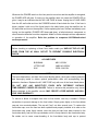
In the event that the DC RAIL FUSES need to be replaced, only one of the fuse types listed
in the table below should be used. Please note that the fuses listed in the table, and their
time-current blowing points, have been carefully selected and thoroughly tested to deliver
optimal performance while still accomplishing their protective functions. Replace these
fuses, individually, only with the specific types listed. DO NOT USE ANY SUBSTITUTE
FUSES WITH DIFFERENT RATINGS, TIME-CURRENT CURVES OR VALUES. Failure
to observe this precaution may cause serious damage to the amplifier circuits, MAY
CREATE A FIRE HAZARD, AND MAY VOID YOUR WARRANTY. For your convenience,
a replacement set of two of the correct DC RAIL FUSES is supplied with each amplifier to
facilitate restoration of the amplifier to operation in the event of a blown fuse.
The GFA-555ms has a massive power supply which remains charged for up to FIVE
MINUTES after the amplifier is turned off and the POWER LED ceases to glow. It also
remains energized when the POWER. LED glows even if the THERMAL PROTECTION
LED is ON. Therefore, you should exercise great caution when connecting arid/or
disconnecting loudspeakers to or from the RIGHT/LEFT STEREO SPEAKER OUTPUTS.
Should you inadvertently short out the RED ("+") and BLACK ("-") STEREO SPEAKER
OUTPUTS, enough power may remain in the power supply to cause sufficient current to
blow the DC RAIL FUSES on the affected channel. When connecting or disconnecting
loudspeakers to or from the RIGHT/LEFT STEREO SPEAKER OUTPUTS, always be
certain to wait at least FIVE MINUTES after turning the amplifier OFF before undertaking
any such procedure.
DC RAIL FUSES
BUSSMAN
AGC-7/250V
LITTELFUSE
BEL
3AG312007/250V
3AG 7A/125V
To remove a blown or suspect fuse from its fuse holder, use only a number 2 Phillips
screwdriver to prevent damage to the fuse holder. Simply press lightly on the fuse-holder
cap and turn counterclockwise. The cap will "pop" out after several turns. To replace the
fuse-holder cap, once the fuse has been replaced and properly installed in its seat on the
fuse-holder cap, press lightly inward, once the fuse and cap have been inserted in the
fuse-holder body, and turn the cap clockwise until it is firmly seated in the fuse-holder body.
Be certain not to cause cross-threading of the fuse-holder body and cap to prevent
damaging the fuse holder. DO NOT FORCE THE FUSE-HOLDER CAP INTO THE
THREADS. Seating of the cap in the fuse-holder body should be easily accomplished
without excessive force.
AC LINE CORD
The AC cord is a 3-conductor, heavy-duty cable supplied with a heavy-duty, molded 3-prong
AC plug. It provides the power to operate all the GFA-555ms's circuits. Its plug should be
inserted in a standard, 120V/60Hz outlet with a minimum capacity of 15amperes and should
have a dedicated branch circuit. It is not recommended that you connect the GFA-555ms
into a branch circuit on which other appliances are used. Since conventional household
branch circuits are often limited to 15amperes, when the GFA-555ms is used in conjunction
with other appliances on the circuit, you may find the current available for the GFA-555ms is
insufficient; particularly in systems using very low-impedance, highly reactive loudspeakers.
NOTE
The GFA-555ms’s power cord is supplied with a "polarized" AC plug as required by
UL/CSA standards and the National Electrical Code. To minimize the risk of electrical
shock, and to insure minimal hum from the system, do not defeat the polarity-insuring
feature of the plug (one wide blade and one narrow blade). To prevent electrical shock, do
not use the polarized plug With an extension cord or receptacle, or other outlet, unless the
blades can be fully inserted to prevent blade exposure.
AC LINE FUSE
The AC LINE FUSE protects the electronic circuits of the GFA-555ms. This fuse, normally,
will blow only if there is an overload within the GFA-555ms. Since this fuse has been
designed to protect the electronic circuits in the GFA-555ms, it is recommended that it be
replaced only with one of the fuses listed in the table below. Please note that the fuses listed
are for operation of the amplifier on 120VAC/60Hz. For the correct fuse values to operate the
GFA-555ms on other voltages and frequency, please consult the Service Manual for this
amplifier available from the ADCOM Technical Service Department.
Whenever the POWER switch on the front panel is turned on and the amplifier is energized,
the POWER LED will glow. If turning on the amplifier does not cause the POWER LED to
glow, it may be an indication that the AC LINE FUSE is blown. Unplug the AC LINE CORD
from the AC wall outlet and turn the POWER0 switch off and check the fuse. If the fuse is
blown, replace it with one of the fuses listed in the table below, plug the amplifier into its
AC-wall outlet and turn on the amplifier. If after replacing the fuse, it blows immediately upon
turning on the amplifier (POWER LED does not glow), a failed electronic component or
other internal malfunction must be suspected. Make no further attempts at fuse replacement
or operation of the amplifier. Refer the problem to competent ADCOM-authorized
service personnel.
NOTE
Before checking or replacing a blown fuse, make certain you UNPLUG THE AC LINE
CORD FROM THE AC WALL OUTLET TO PREVENT POSSIBLE ELECTRICAL
SHOCK.
AC LINE FUSES
BUSSMAN
ABC-12/250V
LITTELFUSE
SOC
3AB314012/250V
CES6-12A/125V
NOTE
The fuses listed above, and their time-current blowing points, have been carefully selected
and thoroughly tested to deliver optimal performance while still accomplishing their
protective functions. Replace the AC LINE FUSE only with one of the fuses listed above.
DO NOT USE ANY SUBSTITUTE FUSES WITH DIFFERENT RATINGS,
TIME-CURRENT CURVES OR VALUES. Failure to observe this precaution may cause
serious damage to the amplifier circuits, MAY CREATE A FIRE HAZARD, AND WILL
VOID YOUR WARRANTY.
To remove a blown or suspect fuse from its fuse holder, use only a number 2 Phillips
screwdriver to prevent damage to the fuse holder. Simply press lightly on the fuse-holder
cap and turn counterclockwise. The cap will "pop" out after several turns. To replace the
fuse-holder cap, once the fuse has been replaced and properly installed in its seat on the
fuse-holder cap, press lightly inward, once the fuse and cap have been inserted in the
fuse-holder body, and turn the cap clockwise until it is firmly seated in the fuse-holder body.
Be certain not to cause cross-threading of the fuse-holder body and cap to prevent
damaging the fuse holder. DO NOT FORCE THE FUSE-HOLDER CAP INTO THE
THREADS. Seating of the cap in the fuse-holder body should be easily accomplished
without excessive force.
AC ON/OFF SWITCH
The AC ON/OFF switch controls power to the power transformer and circuits of the
GFA-555ms. Whenever the GFA-555ms is energized, the red POWER LED will glow. Push
the top of the rocker switch to energize the GFA-555ms. Push the bottom of the rocker
switch to turn the unit off.
POWER LED
This LED will glow whenever the AC ON/OFF switch is turned on and the GFA-555ms is
energized. If the AC LINE FUSE blows, the POWER LED will cease to glow.
The POWER LED indicates that there is AC voltage being fed to the amplifier, but it does not
signify that all the amplifier's circuits are in operation. If, for example, you have blown one or
more of the DC RAIL FUSES., the amplifier will not operate - that is, the amplifier will not
produce any audio signal - even though the POWER LED glows. Similarly, if the THERMAL
PROTECTION LED glows, the amplifier will not produce sound even though the POWER
LED may still glow.
Additionally, the internal power transformer is provided with a thermostat which will interrupt
power into the transformer if its temperature exceeds 125°C. This high a temperature will
seldom, if ever, be encountered unless the amplifier is subjected to abnormal conditions,
such as operation into loads of less than 1 ohm at very high listening levels, etc. If the
POWER LED does not glow, the THERMAL PROTECTION LED is out and both the DC
RAIL FUSES and AC LINE FUSE are intact, the indication would be that the thermostat
within the transformer has opened.
Once the temperature within the transformer decreases to a normal level, the thermostat will
reset itself and normal operation will resume. If you are to avoid tripping continually the
thermostat in the transformer, you must reduce the sound level demands into such low
impedances, install auxiliary fan cooling on the amplifier, or both.
For a more detailed description of the operation of the THERMAL PROTECTION LED circuit
and the DC RAIL FUSES, please refer to their respective sections.
INSTANTANEOUS DISTORTION ALERT LEDs
The
INSTANTANEOUS
DISTORTION
ALERT
circuit
is
a
unique
ADCOM
distortion-detection system which reads all forms of non-linear distortion such as THD, 1M,
slew-induced, "clipping", etc. The INSTANTANEOUS DISTORTION ALERT LEDs will light
when distortion reaches 1% regardless of the impedance or the phase angle of the current
voltage and the reactance of the loudspeakers which the amplifier is driving. Sometimes,
when the amplifier is in use, the LEDs may occasionally flicker under high-volume listening,
particularly if you are driving low impedances. This flickering is no cause for concern. The
LEDs are simply warning you that the amplifier is approaching its maximum power output
into the specific loudspeakers which you are using. If, however, the INSTANTANEOUS
DISTORTION ALERT LEDs glow brightly or are on most of the time during playback, you
are overdriving the amplifier and should lower the volume control to reduce the
listening-level demands, or you may blow the DC RAIL FUSES, cause the THERMAL
PROTECTION to be activated or, in extreme cases, damage your loudspeakers.
THERMAL PROTECTION LED
The GFA-555ms is provided with a thermal protection circuit which will shut down the
amplifier if the temperature of either heatsinks reaches 85°C. The THERMAL PROTECTION
LED will light whenever the thermal protection circuit on either channel, or both channels,
has been triggered and the amplifier is inoperative. The thermal protection circuitry will
typically be triggered by very high-power demands into impedances much lower than the
amplifier is capable of driving at those levels. If the output of either channel of the amplifier
ceases abruptly, and the THERMAL PROTECTION LED glows, you will know that its
heatsinks temperature has become unacceptably high and the circuitry is protecting the
amplification devices. Please note that the POWER LED will remain on and the amplifier will
still be energized.
Once the temperature of the heatsinks drops to a safe operating level, the amplifier will
automatically return to operation.
If the amplifier ceases to operate and both the POWER LED and the THERMAL
PROTECTION LED are off, the condition may indicate that the AC LINE FUSE has blown.
Please refer to the section AC LINE FUSE e for instructions on replacing this fuse.
NOTE
ACTIVATION OF THE THERMAL PROTECTION CIRCUITRY IN THE GFA-555ms IS AN
INDICATION THAT THE AMPLIFIER HAS BEEN OVERDRIVEN OR THAT THE LOAD
THE LOUDSPEAKERS ARE PRESENTING TO THE AMPLIFIER IS UNREASONABLY
LOW. IF YOU WISH TO PREVENT RECURRENT ACTIVATION OF THE THERMAL
PROTECTION CIRCUITRY, YOU MUST REDUCE THE VOLUME LEVEL DEMANDS,
RECTIFY THE LOAD-IMPEDANCE CONDITION WHICH MAY BE CAUSING
ACTIVATION OF THIS CIRCUITRY, INSTALL AN AUXILIARY FAN OPTION OR, IN
EXTREME CASES, UNDERTAKE ALL THREE.
CARING FOR YOUR GFA-555ms
Great care has been taken by ADCOM to assure that your amplifier is as flawless in
appearance as it is electronically. The front panel is a heavy- gauge, high-grade aluminum
extrusion carefully finished and anodized for durability. The chassis, top cover and rear
panel are of heavy-gauge steel, both painted and baked. If the front panel, top or sides
should become dusty or fingerprinted, they can be cleaned with a soft Iintless cloth, slightly
dampened with a very mild detergent solution or non-ammonia glass cleaner.
NOTE
DO NOT SPRAY OR USE LIQUIDS OF ANY KIND ON THE SURFACES OF THE
GFA555se. DO NOT EXPOSE THE AMPLIFIER TO RAIN, WATER OR MOISTURE OF
ANY KIND.
SERVICING-North America
ADCOM has a Technical Service Department to answer questions pertinent to the
installation and operation of your unit. In the event of difficulty, please contact us for prompt
advice. If your problem can not be resolved through our combined efforts, we may refer you
to an authorized repair agency, or authorize return of the unit to our plant. To aid us in
directing you to a convenient service station, it would be helpful if you indicate which major
city is accessible to your home.
Please address mail inquiries to:
ADCOM-USA/J&B DISTRIBUTION
Phone or Fax inquiries:
Monday through Friday
PO BOX 54096
PHOENIX, AZ 85078
9:00AM to 4:00PM Arizona Time
Phone Number: 480-607-2277
U.S.A.
email: [email protected]
When calling or writing about your GFA-555ms, be sure to note and refer to its model and
serial numbers as well as the date of purchase and the ADCOM authorized dealer from
whom it was purchased. In the event the unit must be returned for service, you will be
instructed as to the proper procedure when you call or write. UNDER NO
CIRCUMSTANCES SHOULD YOUR UNIT BE SHIPPED TO US WITHOUT PRIOR
AUTHORIZATION, OR PACKED IN OTHER THAN ITS ORIGINAL CARTON AND
FILLERS.
Always ship PREPAID VIA UPS, FDX OR OTHER APPROVED CARRIER. DO NOT SHIP
VIA PARCEL POST, since the packing was not designed to withstand rough Parcel Post
handling. FREIGHT COLLECT SHIPMENTS WILL NOT BE ACCEPTED.
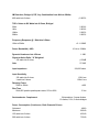
GFA-555ms SPECIFICATIONS
Power Rating (To FTC Requirements)
125 watts continuous average power into 8 ohms at any frequency between 20Hz and
20kHz with both channels driven at less than 0.04% THD.
200 watts continuous average power into 4 ohms at any frequency between 20Hz and
20kHz with both channels driven at less than 0.05% THD.
400 watts continuous average power into 8 ohms at any frequency between 20Hz and
20kHz at less than 0.09% THD, bridged.
IM Distortion (SMPTE)
1 watt to 125 watts into 8 ohms
≦0.009%
1 watt to 200 watts into 4 ohms
≦0.009%
IM Distortion (CCIF, Any Combination from 4kHz to 20kHz)
125 watts into 8 ohms
≦0.002%
200 watts into 4 ohms
≦0.003%
THD + Noise at 125 Watts into 8 Ohms
20Hz
0.004%
1kHz
10kHz
0.003%
0.006%
20kHz
0.020%
THD + Noise at 200 Watts into 4 Ohms
20Hz
0.005%
1kHz
10kHz
0.004%
0.020%
20kHz
0.030%
IM Distortion, Bridged (SMPTE)
1 watt to 400 watts into 8 ohms
≦0.05%
IM Distortion, Bridged (CCIF, Any Combination from 4kHz to 20kHz)
400 watts into 8 ohms
≦0.005%
THD + Noise at 400 Watts into 8 Ohms, Bridged
20Hz
0.004%
1kHz
10kHz
0.004%
0.020%
20kHz
0.050%
Frequency Response @ 1 Watt into 8 Ohms
10Hz to 20kHz
+0. -0.25dB
10 Hz to 100kHz
Power Bandwidth (-3dB)
1.3dB
Dynamic Headroom into 4 Ohms
Signal-to-Noise Ratio, "A" Weighted
125 watts into 8 ohms
≧102dB
27.2dB
Gain
100,000 ohms
Input Impedance
Input Sensitivity
125 watts into 8 ohms
1.38V rms
1 watt into 8 ohms
Damping Factor
123mV rms
20Hz to 20kHz
Rise Time
>400
5kHz,90V peak-to-peak square wave, 20% to 80%
Semiconductor Complement
2.3us
34 transistors, 2 zener diodes,
13 diodes, 2 ICs, 2 diode bridges
Power Consumption (Continuous, Both Channels Driven)
Quiescent
Maximum
48VA
900VA
125 watts into 8 ohms
200 watts into 4 ohms
420VA
730VA
400 watts into 8 ohms, bridged
800VA
GENERAL
Power
120VAC/60Hz
Chassis Dimensions
Maximum Dimensions
5-1/4" (134mm) x 16-15/16" (430mm) x 12-1/8" (308mm)
6” (152mm) x 17" (432mm) x 12-1/2" (318mm)
28.6lbs.(13kgs)
33 Ibs.(15kgs)
Weight
Weight, Packed
Specifications subject to change without notice.
Published by ADCOM LLC
Copyright 2011 ADCOM LLC
All rights reserved
ADCOM and the ADCOM logo are registered trademarks of ADCOM LLC
No part of this manual may be reproduced or electronically transmitted without the express written consent of ADCOM LLC.
ADCOM LLC shall not be liable for any errors contained herein or for any damages arising out of or related to this document
or the information contained herein, even if ADCOM LLC has been advised of the possibility of such damages. This
document is intended for informational and instructional purposes only.
ADCOM LLC reserves the right to make changes
in the specifications and other information contained in this document without prior notification.
any obligation to update the information contained herein.
ADCOM LLC disclaims