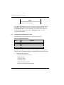
1
KZPSA PCI-to-SCSI Storage Adapter User's Guide Order Number: EK–KZPSA–UG. B01 Digital Equipment Corporation Maynard, Massachusetts Second Printing, April 1995 While Digital believes the information included in this publication is correct as of the date of publication, it is subject to change without notice. Digital Equipment Corporation assumes no responsibility for any errors that might appear in this document. Digital Equipment Corporation makes no representations that the use of its products in the manner described in this publication will not infringe on existing or future patent rights, nor do the descriptions contained in this publication imply the granting of licenses to make, use, or sell equipment or software in accordance with the description. This device complies with Part 15 of the FCC Rules. Operation is subject to the following conditions: (1) this device may not cause harmful interference, and (2) this device must accept any interference received, including interference that may cause undesired operation. This equipment has been tested and found to comply with the limits for a Class B digital device, pursuant to Part 15 of the FCC rules. These limits are designed to provide reasonable protection against harmful interference in a residential installation. Any changes or modifications made to this equipment may void the user's authority to operate this equipment. The KZPSA-BB FCC ID number is: AO9 KZPSAPS. This equipment generates, uses, and can radiate radio frequency energy and, if not installed and used in accordance with the instructions, may cause harmful interference to radio communications. However, there is no guarantee that interference will not occur in a particular installation. If this equipment does cause harmful interference to radio or television reception, which can be determined by turning the equipment off and on, the user is encouraged to try to correct the interference by one or more of the following measures: – Re-orient or relocate the receiving antenna – Increase the separation between the equipment and receiver – Connect the equipment into an outlet on a circuit different from that to which the receiver is connected – Consult the dealer or an experienced radio/TV technician for help The SCSI port should be connected only with shielded data cables. Digital recommends cables such as BN21K and BN31G. These are available in 2M, 3M, 5M and 20M lengths. The following are trademarks of Digital Equipment Corporation: AXP, the Digital logo, and StorageWorks. The following are third-party trademarks: Microsoft and MS-DOS are registered trademarks and Windows NT is a trademark of Microsoft Corporation. 1995 Digital Equipment Corporation. All rights reserved. Printed in USA Contents 1 Product Description 1.1 Introduction................................................................................................. 1–1 1.2 Standards..................................................................................................... 1–4 1.3 Specifications.............................................................................................. 1–4 2 Configuration Guidelines 2.1 2.2 2.3 2.4 2.5 2.6 2.7 2.8 2.9 2.10 2.11 3 Configuration Defaults............................................................................... 2–1 PCI Bus Configuration ............................................................................... 2–2 SCSI Bus Configuration............................................................................. 2–2 SCSI Bus Termination ............................................................................... 2–3 SCSI Termination Power............................................................................ 2–4 SCSI Fast Data Transfers ........................................................................... 2–4 SCSI Bus Reset–on–Boot........................................................................... 2–4 Device Wide Negotiation........................................................................... 2–4 Device Synchronous Negotiation ............................................................... 2–4 Device Tagged Queuing............................................................................. 2–4 Device Disconnects.................................................................................... 2–5 Installing the KZPSA Adapter 3.1 Unpacking.................................................................................................. 3–1 3.2 Hardware Installation Procedure ................................................................ 3–2 4 OpenVMS AXP and OSF/1 Systems 4.1 4.2 4.3 4.4 4.5 4.6 4.7 Software Supplied...................................................................................... 4–1 Completing the KZPSA Installation ........................................................... 4–1 KZPSA Adapter Configuration .................................................................. 4–2 KZPSA SCSI ID ........................................................................................ 4–3 SCSI Termination Power............................................................................ 4–3 SCSI Fast Data Transfer............................................................................. 4–3 KZPSA Device Booting ............................................................................. 4–4 EK–KZPSA–UG. B01 iii KZPSA PCI-to-SCSI Storage Adapter 5 Windows NT AXP Systems 5.1 Software Supplied.......................................................................................5–1 5.2 Completing the KZPSA Installation............................................................5–1 5.3 Installing the Device Driver........................................................................5–3 6 KZPSA Adapter Utilities 6.1 General Overview.......................................................................................6–1 6.2 Configuration and Diagnostic Utility ..........................................................6–2 6.3 Firmware Update Utility........................................................................... 6–10 7 Troubleshooting 7.1 7.2 7.3 7.4 Introduction ................................................................................................7–1 System Power-on Problems ........................................................................7–2 SCSI Device Problems................................................................................7–3 Boot Sequence Problems ............................................................................7–5 Appendix A Additional Information Appendix B Sample KZPSA Adapter Configurations B.1 Configuration Summary............................................................................. B–1 B.2 Bus Converter Configuration (8–bit Single–Ended) ................................... B–2 B.2.1 Single–Ended SCSI Bus Configuration................................................. B–2 B.2.2 SCSI ID Selection ................................................................................ B–2 B.2.3 SCSI Bus Termination.......................................................................... B–2 B.3 RAID Subsystem Configuration................................................................. B–3 B.3.1 Single–Ended SCSI Bus Configuration................................................. B–4 B.3.2 SCSI ID Selection ................................................................................ B–4 B.3.3 SCSI Bus Termination.......................................................................... B–4 B.4 DECsafe Available Server Environment (ASE) Configuration................... B–6 B.4.1 Single–Ended SCSI Bus Configuration................................................. B–6 B.4.2 SCSI ID Selection ................................................................................ B–8 B.4.3 SCSI Bus Termination.......................................................................... B–8 Glossary iv EK–KZPSA–UG. B01 Contents Figures 1–1 2–1 3–1 3–2 6–1 6–2 6–3 6–4 6–5 6–6 6–7 6–8 B–1 B–2 B–3 KZPSA PCI-to-SCSI Storage Adapter........................................................ 1–1 KZPSA Termination Resistor Locations..................................................... 2–3 Typical KZPSA Installations...................................................................... 3–3 Connecting SCSI Cable.............................................................................. 3–5 Initial Screen.............................................................................................. 6–4 Options ...................................................................................................... 6–5 SCSI Options ............................................................................................. 6–6 Configuring Device Specific Parameters .................................................... 6–7 Diagnostics ................................................................................................ 6–8 Error Log Example .................................................................................... 6–9 Firmware Update Utility .......................................................................... 6–10 Firmware Update Utility .......................................................................... 6–11 Bus Converter Configuration......................................................................B–3 RAID Subsystem Configuration .................................................................B–5 DECsafe Available Server Environment (ASE) Configuration ...................B–7 Tables 1–1 1–2 6–1 7–1 7–2 7–3 A–1 B–1 Standards ................................................................................................... 1–4 Specifications............................................................................................. 1–4 Keyboard Functions ................................................................................... 6–2 Power-on Problems Troubleshooting Table................................................ 7–2 SCSI Device Troubleshooting Table .......................................................... 7–3 Boot Sequence Troubleshooting Table ....................................................... 7–5 Additional Hardware Installation Items......................................................A–1 KZPSA Adapter Host-to-Storage Shelf Configurations ..............................B–1 EK–KZPSA–UG. B01 v Revision Record This Revision Record provides a concise publication history of this guide. It lists the guide revision levels, release dates, and reasons for the revisions. It also describes how the changes to affected pages are marked in the guide. The following revision history lists all revisions of this publication and their effective dates. The publication part number is included in the Revision Level column, with the last entry denoting the latest revision. This publication supports the KZPSA PCI-to-SCSI Storage Adapter. Revision Level Date Summary of Changes EK-KZPSA-UG. B01 April 1995 Adds SCSI bus termination note to Chapter 2 and describes installation of plastic card extender option (Chapter 3). EK–KZPSA–UG. B01 vii About This Guide This section identifies the audience of this guide and describes the contents (chapter-bychapter) and structure. In addition, this section includes a list of associated documents and the conventions used in this guide. This guide provides the following information for the KZPSA PCI-to-SCSI Storage Adapter, hereinafter referred to as the KZPSA Adapter, the adapter, or simply as the KZPSA: • General description of the KZPSA • Hardware and software installation procedures • Three examples of how to connect and configure the KZPSA adapter to a storage subsystem and external host Intended Audience This guide is intended for people who will install and maintain the KZPSA adapter in the field. The user should have a general understanding of basic SCSI terminology and installation procedures. Document Structure This guide contains the following chapters: Chapter 1: Product Description Product Description presents a general description of the KZPSA adapter and the PCI-to-SCSI interface. It also lists the operating standards for the adapter and its electrical and environmental specifications. Chapter 2: Configuration Guidelines Configuration Guidelines is intended to help users plan their system configuration. It discusses the SCSI bus configuration, bus termination and power, and describes the bus signals and their functions. EK–KZPSA–UG. B01 ix KZPSA PCI-to-SCSI Storage Adapter Chapter 3: Installing the KZPSA Adapter Installing the KZPSA PCI-to-SCSI Storage Adapter describes how to physically install the KZPSA adapter board into a computer. It provides unpacking and hardware installation information. Chapter 4: OpenVMS AXP and OSF/1 Systems OpenVMS AXP and OSF/1 Systems provides specific information to install and use the KZPSA adapter with either the OpenVMS AXP or OSF/1 operating systems. It explains how to verify the physical installation of the adapter in your system and how to modify some adapter parameters from the system console. Chapter 5: Windows NT AXP Systems Windows NT AXP Systems describes how to install and use the KZPSA adapter with the Windows NT AXP operating system. It explains how to verify the physical installation of the adapter in your system and how to install the KZPSA driver software in Windows NT. Chapter 6: KZPSA Adapter Utilities KZPSA Adapter Utilities describes how to run the KZPSA adapter configuration and diagnostic utility, and how to load the firmware update utility. Chapter 7: Troubleshooting Troubleshooting provides information to help diagnose problems that can occur during the installation of the KZPSA adapter. Appendix A: Additional Information Additional Information provides the Digital part number of some of the additional items you may need when you install the KZPSA adapter. x EK–KZPSA–UG. B01 About This Guide Appendix B: Sample KZPSA Adapter Configurations Sample KZPSA Adapter Configurations describes three possible configurations in which differential and single-ended SCSI devices, housed within a storage enclosure and external to the host system, are interconnected by way of the KZPSA adapter's external SCSI port connector. Associated Documents In addition to this guide, the following documentation is useful to the reader: Document Referenced AXP Systems Firmware Reference Guide Windows NT System Guide StorageWorks Manuals for Storage Shelves and Array Controllers Conventions This guide uses the following documentation conventions: Style Conventions Style Meaning boldface monospace type To be input by the user (e.g. menu picks). Text For emphasis, manual titles, chapter summaries, keyboard key names. plain monospace type italic type Special font (Courier) EK–KZPSA–UG. B01 For filenames and commands. xi 1 Product Description This chapter provides a product description of the KZPSA PCI-to-SCSI Storage Adapter. It also lists the operating standards for the adapter and its electrical and environmental specifications. 1.1 Introduction The KZPSA adapter (Figure 1–1) is a Peripheral Component Interconnect (PCI) to Small Computer System Interface-2 (SCSI-2) adapter. You install the adapter on your computer motherboard through a PCI connector for 32 bit/+5V operation. Each adapter provides connection for one fast, wide differential SCSI bus. Cabling provides the interconnect between the adapter and a storage device. The adapter supports up to 15 devices, including RAID controllers. Both 8-bit differential SCSI bus devices and 16-bit differential SCSI bus devices can be directly connected. To connect single-ended devices, you must use a differentialto-single-ended SCSI bus converter, such as a Digital DWZZA bus converter. Figure 1–1 KZPSA PCI-to-SCSI Storage Adapter EK–KZPSA–UG. B01 1–1 KZPSA PCI-to-SCSI Storage Adapter The adapter’s processor minimizes the SCSI I/O overhead of the host computer’s processor by interpreting host commands and translating them into specific device commands. This includes support for direct data transfer to host memory, coding device-specific commands into specific command scripts, and supporting internal command queues with disconnect/reconnect functionality. The KZPSA is capable of 32-bit bus master data transfers, including PCI enhanced data transfer commands. The host adapter supports most SCSI-2 functions. The host adapter supports multithreaded I/O operations, thereby allowing simultaneous operations on multiple SCSI targets or Logical Units (LUNs). In systems with multiple targets, the Disconnect/Reconnect feature optimizes SCSI bus usage. In systems that have fragmented memory buffers, the Scatter/Gather feature provides high performance. In addition to its normal role of SCSI initiator, the KZPSA provides support for target mode operations. In this mode, the KZPSA can receive incoming SCSI-2 processor commands intended for its locally connected host. This functionality makes the KZPSA, with operating system support, an integral component in advanced-system configurations such as the high availability DECsafe Available Server Environment. The KZPSA has several parameters the user can change to optimize the adapter’s functionality within the system. These parameters may be changed using the configuration utility software included with the module. This utility provides the capability of changing settings on the boards NVRAM without having to make physical changes to the host adapter board. Some of the major features of the KZPSA are: 1–2 • Compliance with Intel PCI version 2.0, ANSI X3t9.2 SCSI-2 Standard, and U.S. and international safety/emissions standards • Fast-Narrow SCSI (8-bit, 10 Mbytes per second, 7 devices) • Fast-Wide SCSI (16-bit, 20 Mbytes per second, 15 devices) • On-board NVRAM that can be customized using a configuration utility – no need to remove the computer cover to change configuration EK–KZPSA–UG. B01 Chapter 1. Product Description PCI Bus Interface • Up to 133 MB/sec data transfer rate on the PCI bus • PCI single and dual address cycles support • PCI bus address and data parity generation/verification • PCI bus master for data transfer SCSI-2 Implementation • Concurrent support for asynchronous and Fast SCSI synchronous devices • Concurrent support for 8- and 16-bit SCSI devices • Scatter/Gather • Disconnect/Reconnect • Fully multithreading/multitasking • 68-pin high density external connector • Tagged Queue support • Target Mode support • Support of multiple LUNs • SCSI termination power control • Parity handling in Data, Message, Status, Selection/Reselection, and Command phases Maximum Off-loading of Host CPU Requirements • Onboard adapter processor automates SCSI processing • Low SCSI processing overhead • Bus Master DMA implementation • Task scheduling and message-based communication Support and Information Services The KZPSA Adapter is designed for easy installation and use. If you need further assistance, please contact the Digital Customer Support Center. EK–KZPSA–UG. B01 1–3 KZPSA PCI-to-SCSI Storage Adapter 1.2 Standards The KZPSA adapter conforms to the Standards listed in Table 1–1. Table 1–1 Standards Industry Standard 1.3 Description SCSI-2 ANSI X3T9.2/86-109 - SCSI Specification. PCI PCI Local Bus Specification Rev 2.0. FCC Class B Residential use. Specifications The electrical and environmental specifications for the KZPSA adapter are listed in Table 1–2. Table 1–2 Specifications Characteristic Specification Performance: Throughput Burst Transfer Rate Operating temperature Storage temperature 1–4 Greater than 2000 single-sectored I/Os/sec. 20 MB/sec. peak (for fast wide transfers). o o o 0 to 50 C (32 F to 122 F) o o o o -10 C to 40 C (-50 F to 104 F) Operating relative humidity 10% to 90% (noncondensing) Storage relative humidity 8% to 80% (noncondensing) Minimum airflow 150 linear feet/minute (lfm) on the component side of the module and 50 lfm on the etch side. Power dissipation 10 W (typical) Current consumption 2 A at +5 V (typical) 4 A at +5V (maximum) (including SCSI termination power) Mean Time Between Failure (MTBF) > 500,000 hours 25 W (maximum) EK–KZPSA–UG. B01 2 Configuration Guidelines Before you install the KZPSA PCI-to-SCSI storage adapter in your computer, you need to become familiar with the configuration guidelines for the host adapter and its SCSI bus. This chapter will help you plan your system configuration. It discusses the SCSI bus configuration, bus termination and power, and describes bus signals and their functions. 2.1 Configuration Defaults Your KZPSA adapter has been configured at the factory as follows: Adapter Attribute Default Reason to change SCSI ID 7 If there are multiple SCSI adapters on the same SCSI bus. SCSI Termination Present Yes If KZPSA is not at one end of the bus. SCSI Termination Power Yes If too many nodes supply termination power, there is a potential safety issue because too much current is available. SCSI Fast Data Transfer Yes If there are single ended segments greater than 3 meters. SCSI Bus Reset on Boot No To allow SCSI bus resets during Boot. Device Attribute Default Reason to change Wide Negotiation Yes If the device is incompatible with wide negotiation. Synchronous Negotiation Yes If the device is incompatible with synchronous negotiation. Tagged Queuing Yes If the device is incompatible with tagged command queuing. Disconnect Yes To improve single device performance. EK–KZPSA–UG. B01 2–1 KZPSA PCI-to-SCSI Storage Adapter These defaults were chosen for optimum performance of the adapter. If they are acceptable for your configuration, proceed to Installation in Chapter 3. Each of these attributes, except for termination present, can be changed by using the configuration utility described in Chapter 6. 2.2 PCI Bus Configuration PCI Adapters are automatically configured by the power-up software. The adapter addresses and interrupts are set without jumpers. 2.3 SCSI Bus Configuration The KZPSA allows direct connection of both 8-bit (narrow) and 16-bit (wide) differential SCSI bus devices. You can connect up to 15 devices to your adapter. The total bus length should not exceed 25 meters for a differential SCSI bus. For the KZPSA to support single-ended devices, you must use a differential-tosingle-ended SCSI bus converter such as the Digital DWZZA bus converter. With a DWZZA bus converter (16-bit differential to 8-bit single-ended), you can connect up to 7 single-ended SCSI bus devices in addition to 8 wide differential SCSI bus devices to the KZPSA adapter. With a DWZZB bus converter (16-bit differential to 16-bit single-ended), you may connect up to 15 single-ended devices. The total bus length should not exceed 3 meters for a fast single-ended bus or 6 meters for a slow single-ended bus. The SCSI ID for the KZPSA adapter is defaulted to 7. If multiple adapters (see your host system manual for possibilities) are used on the same SCSI bus, the recommended SCSI IDs of the adapters should be 7, 6, 5, etc. Specific applications, such as Available Server Environment in Appendix B, may make alternative recommendations. Only one device can use the SCSI bus at a time. When two or more devices try to use the bus at the same time, the priority arbitration scheme determines which device goes first and which devices must wait. The SCSI ID priority from highest to lowest is as follows: SCSI ID 7-6-5-4-3-2-1-0-15-14-13-12-11-10-9-8. 2–2 EK–KZPSA–UG. B01 Chapter 2. Configuration Guidelines 2.4 SCSI Bus Termination Bus termination is required at each end of the SCSI bus. Typically, the SCSI bus has the KZPSA adapter at one end and some storage device at the other end. In this case, you must have termination resistor packs (Z1–Z5, Figure 2–1) installed in the KZPSA adapter; these are installed at the factory. There should not be any termination at any of the intermediate devices. If the KZPSA is used in the middle of the SCSI bus, the termination resistors should be removed from that KZPSA. NOTE When connecting a "Y-cable" (BN21W-OB) to the KZPSA, be sure to remove termination resistors Z1–Z5 from the adapter. In this configuration, the KZPSA is no longer at the end of the bus and external termination must be installed. Figure 2–1 KZPSA Termination Resistor Locations EK–KZPSA–UG. B01 2–3 KZPSA PCI-to-SCSI Storage Adapter 2.5 SCSI Termination Power It is normal for adapters, not devices, to supply termination power to the SCSI bus. The KZPSA adapter is configured at the factory to supply 1.5 amps of termination current. Although each SCSI node may supply termination power to the bus, a single source from the host adapter is sufficient. No more than four sources of termination power on a SCSI bus is recommended. 2.6 SCSI Fast Data Transfers Eight-bit devices that allow fast data transfers will transfer data at rates greater than 5 Mbytes/sec., usually at the normal 10 Mbytes/sec. rate. The actual speed is negotiated between the adapter and the device at the start of a transfer. If disabled, this will be limited to 5 Mbytes/sec. This allows for single-ended bus segments that exceed the three meter fast limit and, therefore, must be speed restricted. 2.7 SCSI Bus Reset-on-Boot For some high-availability configurations, SCSI bus resets on system boot are not desired as there may be another adapter on the same bus. This defaults to no SCSI bus resets sent on the bus during boot, but can be configured to issue them. 2.8 Device Wide Negotiation Because some older devices fail to conform to the SCSI specification for wide negotiation, they may not be recognized by the KZPSA unless wide negotiation is disabled. The adapter default allows wide negotiation. 2.9 Device Synchronous Negotiation Because some older devices fail to conform to the SCSI specification for synchronous negotiation, they may not function correctly unless synchronous negotiation is disabled. The adapter default allows synchronous negotiation. 2.10 Device Tagged Queuing Because some older devices fail to conform to the SCSI specification for tagged command queuing, they may not function correctly if tagged command queuing is allowed. The adapter default allows tagged command queuing. 2–4 EK–KZPSA–UG. B01 Chapter 2. Configuration Guidelines 2.11 Device Disconnects To optimize overall SCSI bus performance, the adapter default allows device disconnects. This means that a device that realizes a need for a lengthy delay before the next data can be transferred can disconnect this operation to allow another device to utilize the bus, and resume it later when the data is available. This disconnect may also be disabled when there is only a single device on the bus. By preventing disconnects, performance can be improved as the disconnect / reconnect protocol time is avoided. When a single device is connected to the SCSI bus, optimum performance is usually obtained by disabling disconnects. EK–KZPSA–UG. B01 2–5 3 Installing the KZPSA Adapter This chapter describes how to install the KZPSA adapter board into a computer. 3.1 Unpacking Unpack the KZPSA PCI-to-SCSI Storage Adapter kit and place the contents (board, diskettes, etc.) in an area where they are protected and accessible for installation. Perform an inventory of the contents. The kit should contain the following items: • KZPSA Adapter Board • Software Diskette • Alternate Board Extender • User’s Guide • Release Notes NOTE Refer to the Release Notes supplied with the kit for the latest Digital component part numbers. If your KZPSA kit was damaged in shipping, contact the shipping company. If you need repair or warranty service in the United States, contact the Customer Returns Center at 1-800-225-5385. For repair or warranty service outside the United States, contact the Customer Support Center for your area. Additional information about other items you may need to install the KZPSA in your computer is listed in Appendix A. EK–KZPSA–UG. B01 3–1 KZPSA PCI-to-SCSI Storage Adapter 3.2 Hardware Installation Procedure CAUTION Static electricity can destroy the circuits on the KZPSA adapter. Discharge static electricity by touching the system box's metal frame before handling the KZPSA module or any other modules. 1. Power down your computer and remove the covers to access the motherboard. Refer to your host system manual for general instructions on installing adapters. NOTE Two board extender guides are included in the KZPSA Adapter Kit; one factory-installed and one optional guide for alternate system configurations. If the installed extender does not fit in your system, replace it with the other extender as shown in Figure 3–1. 2. Install the KZPSA adapter board in your host computer; the board connector is held in place with a screw you remove from a blank panel as shown in Figure 3–1. Replace the factory-installed guide with the correct configuration for your system if necessary. 3. Replace your host computer covers; refer to your host computer manual. 4. Connect the SCSI cable as shown in Figure 3–2. 5. The KZPSA adapter is now physically installed. However, you must power on your system to have the host firmware recognize and configure the KZPSA adapter. 6. Power on your host computer. Proceed to Chapter 4 for OpenVMS AXP or DEC OSF/1 systems. Proceed to Chapter 5 for Windows NT AXP systems. 3–2 EK–KZPSA–UG. B01 Chapter 3. Installing the KZPSA Adapter Figure 3–1 Typical KZPSA Installations With factory-installed metal extender guide. With alternate metal extender guide. EK–KZPSA–UG. B01 3–3 KZPSA PCI-to-SCSI Storage Adapter Figure 3–1 Typical KZPSA Installations (continued) With alternate plastic extender guide. 3–4 EK–KZPSA–UG. B01 Chapter 3. Installing the KZPSA Adapter Figure 3–2 Connecting SCSI Cable EK–KZPSA–UG. B01 3–5 4 OpenVMS AXP and OSF/1 Systems This chapter provides information which is unique to the installation and use of your KZPSA adapter with either the OpenVMS AXP or OSF/1 operating systems. The information includes how to verify the physical installation of the adapter in your system and how to modify some adapter parameters for the console. Some adapter parameters require the use of KZPSA utilities as described in Chapter 6. 4.1 Software Supplied Your KZPSA adapter comes with a floppy diskette that contains various tools used during the installation and verification process as well as the Windows NT AXP device driver. This diskette is labeled KZPSA Alpha AXP Software. This diskette is a FAT-formatted diskette containing the KZPSA firmware update utility (fwupdate.exe) and the KZPSA configuration and diagnostic utility (cnfgdiag.exe). The diskette also holds a file containing the current firmware in the adapter. This is shipped in case the firmware in the adapter gets corrupted. It can be loaded into the KZPSA via the KZPSA firmware update utility. Refer to Chapter 6, KZPSA Utilities, for more information. Locate your diskette and make a copy of it now. Store the original in a safe place. 4.2 Completing the KZPSA Installation After the physical installation, the KZPSA adapter is ready for use. On system power-on the SRM console requests that the KZPSA adapter execute its built-in self test (BIST). BIST covers all the components on the KZPSA, excluding the SCSI Bus and PCI Bus Drivers. If an error is detected on the KZPSA, the SRM console will display: KZPSA BIST failed, %S failed (%S = SRAM, OPUS, etc.) EK–KZPSA–UG. B01 4–1 KZPSA PCI-to-SCSI Storage Adapter If there is an error, try system power-on again. If the KZPSA error persists, refer to Chapter 7, Troubleshooting. NOTE If the KZPSA passes self-test, no message is displayed at console boot. Enter "show config" at the console prompt to see if the devices on the KZPSA SCSI bus can be accessed. This command displays the system configuration as determined by the SRM console during power-up (Refer to your AXP Systems Documentation.) This display should identify the KZPSA adapter and an indented list of attached devices. 4.3 KZPSA Adapter Configuration There are three parameters that you can and may want to change before booting the operating system. For more information about the parameters, read Chapter 2, Planning your System Configuration. Each of these parameters are changed using the set command. The parameters are: • KZPSA SCSI ID • SCSI Termination Power • SCSI Fast Data Transfer If the defaults are OK, and you don’t want to use a KZPSA device as a boot device, you’re done! Boot the system and enjoy. If you want to configure a KZPSA device as a boot device, go to the last section of this chapter (KZPSA Device Booting). 4–2 EK–KZPSA–UG. B01 Chapter 4. OpenVMS AXP and OSF/1 Systems 4.4 KZPSA SCSI ID The SCSI ID of the KZPSA adapter is set by default to 7. If you want to change it, enter the console command as follows: set pk*0_host_id # where: * is the controller ID from show config and # is the SCSI_id (0-7) 4.5 SCSI Termination Power The KZPSA adapter supplies SCSI termination power by default. To change it so that the KZPSA does not supply power, enter the console command as follows: set pk*0_termpwr # where: * is the controller ID from show config, # = 0 for disable termpwr, and # = 1 for enable termpwr 4.6 SCSI Fast Data Transfer The KZPSA adapter is supplied with the speed set to fast by default. The fast speed is 10 megabytes/second for a narrow SCSI bus and 20 megabytes/second for a wide bus. The slow speed is 5 megabytes/second for a narrow bus and 10 megabytes/second for a wide bus. These parameters apply to all devices attached to this adapter. To alter SCSI speed for SCSI devices, enter the SCSI fast command at the console as follows: set pk*0_fast # where: * is the controller ID from show config, # = 0 for a slow SCSI speed, and # = 1 for a fast SCSI speed EK–KZPSA–UG. B01 4–3 KZPSA PCI-to-SCSI Storage Adapter 4.7 KZPSA Device Booting The SRM console can be used to set a default device, such as a device on the KZPSA SCSI bus, to boot the operating system. To boot the operating system from a device on the KZPSA adapter, define the default boot device at the console as follows: set bootdef_dev device_name where: device_name = name of your boot device which is identified with the show "config" or "show device" command. 4–4 EK–KZPSA–UG. B01 5 Windows NT AXP Systems This chapter provides information which is unique to the installation and use of your KZPSA adapter with the Windows NT AXP operating system. The information includes how to verify the physical installation of the KZPSA adapter in your system, and how to install the KZPSA driver software in Windows NT. Refer to Chapter 6 for a description of the KZPSA Adapter Utilities needed to perform the KZPSA adapter configuration and firmware installation. 5.1 Software Supplied Your KZPSA adapter comes with a floppy diskette that contains various tools used during the installation and verification process as well as the Windows NT AXP device driver. This diskette is labeled KZPSA Alpha AXP Software. This diskette is a FAT-formatted diskette containing the KZPSA firmware update utility (fwupdate.exe) and the KZPSA configuration and diagnostic utility (cnfgdiag.exe). The diskette also holds a file containing the current firmware in the adapter. This is shipped in case the firmware in the adapter gets corrupted. It can be loaded into the KZPSA via the KZPSA firmware update utility. Refer to Chapter 6, KZPSA Utilities, for more information. Locate your diskette and make a copy of it now. Store the original in a safe place. 5.2 Completing the KZPSA Installation To complete the installation of the KZPSA adapter in your Windows NT AXP system, perform the following steps: 1. If you have not already done so, install the KZPSA adapter into your Alpha AXP system following the procedure in Chapter 3 of this guide. EK–KZPSA–UG. B01 5–1 KZPSA PCI-to-SCSI Storage Adapter 2. Power up your system; the Alpha AXP should go through its start up sequence and then display the ARC Boot Menu on your display terminal. Typically, your display should look like the following: (Several lines of menu choices are displayed here) If you do not see this menu, refer to your system documentation for more information about initially setting up your Alpha AXP. Return to this procedure when you have the Boot Menu displayed. 3. From the Boot Menu, select the Supplementary Menu item. 4. Next, select the Display Hardware Configuration item. The system will now display several pages of information about your Alpha AXP system. 5. Press the Return or Enter key to move through the pages until your screen has the PCI Slot Information display. Your screen should look similar to the following: 5–2 Bus Virtual Slot Function Vendor Device Rev. Device Type 0 0 0 6 7 13 0 0 0 1000 8086 1011 1 482 8 2 3 1 SCSI EISA SCSI EK–KZPSA–UG. B01 Chapter 5. Windows NT AXP Systems 6. Note that the third line in the list contains a Vendor Id field of “1011” and a device type of “8”. These two values uniquely identify the KZPSA. Search your display for a line (or lines if you installed more than one KZPSA) containing these exact values. If there is no entry that corresponds to the KZPSA, your adapter may not be correctly installed. Power off your system and repeat the installation process in Chapter 3 of this guide, then this procedure. If successful, continue with the next step. Otherwise, refer to the troubleshooting information in Chapter 7. 7. When you have found all the installed KZPSA adapters listed in step 5, continue to press Enter until you have returned to the Supplementary Menu, then select the Boot Menu item to return to that menu. 8. If you need to modify the parameters of the adapter for your installation (see Chapter 2 for a discussion of adapter parameters), select Run a Program from the Boot Menu and follow the steps in Chapter 6, “KZPSA Adapter Utilities”. Continue with Section 5.3 below to install the KZPSA device driver. 5.3 Installing the Device Driver This procedure describes how to install the device driver after the Windows NT operating system is installed. Proceed as follow: 1. Log into the Windows NT system with Administrator privileges. 2. Click on the Windows NT Setup icon in the main program group. 3. Select the Options menu in the Windows NT Setup window. 4. Select the Add/Remove SCSI Adapter function. 5. Click on the Add button in the dialog box. 6. A warning message is displayed; click on the OK button in the Confirm box. 7. From the list of adapters on the display, select Other. You may have to click on the list to reveal all of the options including the "Other" option. EK–KZPSA–UG. B01 5–3 KZPSA PCI-to-SCSI Storage Adapter 8. Insert the diskette labeled KZPSA Alpha AXP Software into the floppy drive. The prompt “a:\” is displayed for the default drive. 9. Click on OK at the prompt. 10. The name of the driver (DECKZPSA.SYS) is displayed. Click on OK. 11. The Select Adapter Option box displays the name of the adapter (DECKZPSA). Click on the Install button. 12. The Windows NT Setup dialog box displays the path information from step 8 above. Click on the Continue button to copy the driver to Windows NT. 13. When the operation is completed, click on the Close button. 14. Select Exit to leave the Windows NT Setup function and remove the diskette from the drive. 15. Shut down the system and reboot Windows NT. If the system does not reboot, refer to your Windows NT System Guide for assistance. The device driver is now installed and your KZPSA adapter is ready for use with your Alpha AXP Windows NT system. There is no support for using KZPSA devices as boot devices under Windows NT AXP. 5–4 EK–KZPSA–UG. B01 6 KZPSA Adapter Utilities This chapter describes the KZPSA Adapter Utilities. It describes how to run the Configuration and Diagnostic Utility and the Firmware Update Utility. 6.1 General Overview Two of the KZPSA Utilities run from the ARC console. After you power up your system, the Alpha AXP should go through its start up sequence and then display the ARC Boot Menu on your display terminal. Typically, your display should look like the following: NOTE If you do not see this menu, refer to your system documentation for more information about initially setting up your Alpha AXP to run from the ARC console. Return to this procedure when you have the Boot Menu displayed. (Several lines of menu choices displayed here) EK–KZPSA–UG. B01 6–1 KZPSA PCI-to-SCSI Storage Adapter NOTE Refer to the Release Notes for the minimum revision levels of the ARC firmware. Select Run a program from the Boot menu. Place the utilities diskette into the floppy drive. If you want to invoke the configuration/diagnostic utility, type a:\cnfgdiag.exe <cr> at the “Program to run” prompt. If you want to invoke the firmware update utility, type a:\fwupdate.exe <cr> at the “Program to run” prompt. 6.2 Configuration and Diagnostic Utility The following keys do most of the basic operations to the utility: Table 6–1 Keyboard Functions Key Function Arrow Select items in a menu and manipulate the cursor. Spacebar Toggle a highlighted entry. Enter Select a highlighted entry. Escape Exit out of current window / stop a diagnostic test. The KZPSA configuration and diagnostic utility (cnfgdiag.exe) allows you to configure and test your KZPSA adapter by displaying the following information: • Adapter Specific Parameters: – Firmware and hardware revisions – KZPSA SCSI ID – Termpower status – Termination status – KZPSA virtual slot location – SCSI devices connected to the KZPSA 6–2 EK–KZPSA–UG. B01 Chapter 6. KZPSA Adapter Utilities • Device specific parameters: – Wide negotiation – Synchronous negotiation – Tagged queuing – Disconnect • Fast SCSI mode status • Bus reset on boot status • Hardware and firmware error logs The following information can be changed by this utility: • KZPSA SCSI ID • Termpower status • Fast SCSI mode status • Bus reset on boot status • Device specific parameters: – Wide negotiation – Synchronous negotiation – Tagged queuing – Disconnect A power-on self-test (POST) and a SCSI device self-test can be invoked from this utility. The user can also reset the SCSI bus from this utility. Figure 6–1 shows the initial screen. EK–KZPSA–UG. B01 6–3 KZPSA PCI-to-SCSI Storage Adapter Figure 6–1 Initial Screen Use the arrow keys to select the KZPSA you wish to configure or test. Once selected, press Enter to proceed to the Options Window (Figure 6–2). 6–4 EK–KZPSA–UG. B01 Chapter 6. KZPSA Adapter Utilities Figure 6–2 Options Use the arrow keys to select the option you wish to proceed with. You can select the following: • SCSI options This allows the user to see devices connected to the KZPSA and modify parameters associated with them. It also allows users to configure SCSI parameters such as fast SCSI mode, supply termpower from the KZPSA, tagged command queuing, and SCSI reset on boot. The user can also reset the SCSI bus from SCSI options. • Diagnostics Allows the user to run POST and SCSI device self-tests. • Logs Allows the user to display firmware and hardware error logs. Once the option is selected, press Enter to proceed with that option. EK–KZPSA–UG. B01 6–5 KZPSA PCI-to-SCSI Storage Adapter Figure 6–3 SCSI Options Use the arrow keys to select the following: • List existing SCSI devices • Configure device specific parameters • Reset the SCSI bus These functions are described in detail in Chapter 2. Use the spacebar to : • Change the SCSI ID (This increments the SCSI ID up to 15 and then goes back to 0) • Toggle Fast Mode and Reset-on-Boot from Enabled to Disabled • Toggle Termpower from Supplied to Not Supplied Select Save and Exit to save parameter modifications. Select Use Default Setting to return to the factory default settings. 6–6 EK–KZPSA–UG. B01 Chapter 6. KZPSA Adapter Utilities Figure 6–4 Configuring Device Specific Parameters Use the arrow keys to move through the device and parameter choices. Use the spacebar to toggle between YES and NO. Select Save and Exit to save parameter modifications. Select Use Default Setting to return to the factory default settings. The user has the ability to modify the following parameters defined in Chapter 2: • Synchronous negotiation • Wide negotiation • Tagged Queuing • Forced Disconnect A YES disables the specified device from negotiating or implementing the specified parameter. A NO allows the specified device to negotiate or implement the specified parameter. EK–KZPSA–UG. B01 6–7 KZPSA PCI-to-SCSI Storage Adapter Figure 6–5 Diagnostics The user can run the Power-On Self Test (POST) or SCSI Device Self Tests. Use the spacebar to toggle the Diagnostic Test from Power-On Self Test to SCSI Device Self Test. Press the down arrow key to select the Error Action. Use the spacebar to toggle through to possible error actions. The possible error actions are: Halt on Error The diagnostic test stops when an error occurs. Loop on Error The diagnostic test runs the specific failing test repeatedly. Continue on Error The diagnostic test continues to run saving the first 10 errors buffer. (This only occurs if Loop At End is YES). Press the down arrow key again to select Loop At End. Use the spacebar to toggle from NO to YES. Press Enter to start the test. 6–8 EK–KZPSA–UG. B01 Chapter 6. KZPSA Adapter Utilities Figure 6–6 Error Log Example EK–KZPSA–UG. B01 6–9 KZPSA PCI-to-SCSI Storage Adapter 6.3 Firmware Update Utility NOTE The KZPSA firmware requires approximately one minute to load in the following procedure. The KZPSA firmware can be loaded via the firmware update utility (fwupdate.exe). It allows the user to change the firmware without replacing the physical ROM. The first screen of the firmware update utility is shown in Figure 6–7. Figure 6–7 Firmware Update Utility Use the arrow keys to select the KZPSA you wish to update along with the firmware you wish to load as shown in the example of Figure 6–8. If there is only one KZPSA in your system and one revision of firmware on your floppy, press Enter twice to initiate loading the firmware from the floppy diskette into system memory. 6–10 EK–KZPSA–UG. B01 Chapter 6. KZPSA Adapter Utilities Figure 6–8 Firmware Update Utility Pressing Enter initiates the firmware update process. Pressing the Esc key aborts the update. Reset your system after a successful firmware update for new firmware to take effect. EK–KZPSA–UG. B01 6–11 7 Troubleshooting This chapter provides troubleshooting information to help diagnose problems that can occur during the installation of the KZPSA adapter. If you experience difficulty in installing or verifying the operation of the adapter, refer to the information in the troubleshooting tables to isolate and diagnose the problem. 7.1 Introduction Troubleshooting is the process of isolating and diagnosing problems. This chapter provides solutions to problems that can occur during the installation of the KZPSA adapter. If you experience difficulty in installing or verifying the adapter, use the information in this chapter to isolate and diagnose the problem. The troubleshooting techniques described in this chapter do not identify all possible problems with your KZPSA adapter, nor do the actions suggested remedy all problems. If a problem is not described, or if the actions suggested do not solve the problem, call your Digital services representative. For problems that may be related to the host, refer to your host system documentation. The troubleshooting information presented in this chapter is divided as follows: • System Power-on Problems (Table 7–1) • SCSI-Device Problems (Table 7–2) • Boot-Sequence Problems (Table 7–3) EK–KZPSA–UG. B01 7–1 KZPSA PCI-to-SCSI Host Adapter 7.2 System Power-on Problems After you turn on your host system, the CPU either performs a series of self-tests or enters the console mode. Table 7–1 describes possible problems that could occur during self-tests, specifies their probable cause, and provides corrective action. Table 7–1 Power-on Problems Troubleshooting Table 7–2 Symptom Probable Cause Corrective Action System self-tests halt with error message or error summary displayed on console terminal. System detected an error while running its self-test. Check that the KZPSA and system boards are firmly seated. Check connections to external peripherals. Record the number following the question mark in the error message or error summary and call your Digital service representative. EK–KZPSA–UG. B01 Chapter 7. Troubleshooting 7.3 SCSI Device Problems Table 7–2 lists a SCSI device problem, specifies the probable causes, and suggests corrective actions for each probable cause. Table 7–2 SCSI Device Troubleshooting Table Symptom Probable Cause Corrective Action SCSI device does not appear in the configuration display after the SRM console command, Device cannot negotiate wide or synchronous transfers. Use the cnfgdiag utility to disable (see Chapter 6). Duplicate SCSI IDs Ensure that each SCSI device has a unique SCSI ID. KZPSA adapter is in an unknown state. Initialize the adapter with the SRM console command, p00>>show config or, SCSI device does not appear in the List Existing SCSI Devices display selected from the cnfgdiag utility. (P00>>> init) or, by pressing the systems reset button. EK–KZPSA–UG. B01 SCSI device or bus is hung. Reset the SCSI bus via the cnfgdiag utility (see Chapter 6.) Cable is not connected to the SCSI device. Check cable connections. SCSI device(s) not plugged in and turned on before system power up. Power up all external SCSI devices, and then power up system. 7–3 KZPSA PCI-to-SCSI Host Adapter Table 7–2 SCSI Device Troubleshooting Table (Continued) Symptom Probable Cause Corrective Action SCSI device does not . . . SCSI bus not terminated properly. Ensure each end of the bus is terminated. Total length of SCSI bus too long. Check total length of SCSI bus as follows: Fast Single-ended, 3 meters, maximum. Slow single-ended, 6 meters, maximum. Fast differential, 25 meters, maximum. Defective SCSI device. 7–4 Replace SCSI device. EK–KZPSA–UG. B01 Chapter 7. Troubleshooting 7.4 Boot Sequence Problems Table 7–3 describes possible problems during the boot sequence, specifies their probable cause, and suggests corrective actions. Table 7–3 Boot Sequence Troubleshooting Table Symptom Probable Cause Boot failure Incorrect boot device was specified. Redefine the default boot device at the SRM console as described in Section 4.7 of this guide. Note: Booting "Windows NT" through the KZPSA adapter is not supported. KZPSA is not terminated properly. Ensure each end of the SCSI bus is terminated. KZPSA is in an unknown state. Initialize the adapter by either entering the SRM console “init” command or press the system reset button. KZPSA is not terminated properly. Ensure each end of the SCSI bus is terminated. Operating system not configured correctly. Reconfigure system software. Refer to system documentation. Operating system does not contain device driver or driver not installed correctly. If running Windows NT, ensure the device driver is installed. If running OSF/1, ensure that the OS revision level supports the KZPSA. Device not recognized during boot. EK–KZPSA–UG. B01 Corrective Action 7–5 Release Notes KZPSA SCSI Storage Adapter Module Be sure to read these notes before installing the KZPSA SCSI Storage Adapter module into your AXP workstation or server. Introduction The KZPSA SCSI Storage Adapter is a high-performance Peripheral Component Interconnect (PCI) option module that serves as a pathway between the system’s PCI I/O bus and a single 16-bit Fast Wide Differential SCSI bus. This document describes any known issues or restrictions when using the KZPSA SCSI Adapter within your system configuration. This document contains these sections: • • • • • PARTS LIST FOR KZPSA-BB SUPPORTED AXP SYSTEMS VERIFIED DEVICE LISTING MANDATORY CONSOLE FW UPDATE RESTRICTIONS Parts List for KZPSA-BB Part Number Description EK-KZPSA-RN Release Notes for the KZPSA-BB (this document) 54-22944-01 KZPSA PCI to FWD SCSI Module EK-KZPSA-UG KZPSA SCSI Storage Adapter User’s Guide AK-QGTNB-CA KZPSA Alpha AXP Software diskette AK-QK57A-CA AlphaServer 1000 Console Update for KZPSA AK-QK58A-CA AlphaServer 2000, 2100 Console Update for KZPSA Supported AXP Systems The KZPSA is supported on the following AXP servers: • • • AlphaServer 1000 AlphaServer 2000 AlphaServer 2100 Copyright © Digital Equipment Corporation 1995 All Rights Reserved EK-KZPSA-RN. A01 Page 1 StorageWorks KZPSA SCSI Storage Adapter Verified Device Listing Device Type Note FW REV OSF/1 8-bit Single-Ended Devices Windows NT RZ25 RZ25L RZ26 (DSP3105S) 0900 0008 X384 Pass Pass Pass Pass Pass Pass RZ26L RZ28 440C 441C Pass Pass Pass Pass RZ28B RZ73 RZ74 0006 T366 427H Pass Pass Pass Pass Pass Pass 430B 9003 Pass Pass Pass Pass 0491 04AT 045H 02B5 00X2 4.5d Pass Pass Pass Not Supported Pass Pass Pass TZ86 TZ87 1 TLZ06 TLZ07 TKZ09 TZK10 TZK11 RRD42 RRD43 RRD44 RZ26L-VW RZ28-VW RH27B-Z (RZ26) RZG73-E (RZ73) TZ87D HSZ40 (RAID Controller) Pass Pass Pass Pass 2 1084 Pass 3 1094 Pass 16-bit Single-Ended Devices 4 442E Pass 4 X442 Pass 8-bit Differential Drives 392A Pass T392 Pass 9003 Pass 16-bit Differential Drives 5 V20Z In Process Pass Pass Pass Pass Pass Pass Pass Pass HP C2247 1Gb SEAGATE ST31200WD 1 Gb SEAGATE ST12400WD 2 Gb SEAGATE ST12550WD 2 Gb 0BA4 8042 8040 0004 Pass Pass Pass Pass Pass Pass Pass DSP3107LSW 441C Pass Pass Notes: 1) Read/Write failures have been observed when this device is installed in the slot next to the power supply in a BA350 storage shelf. ALWAYS INSTALL THIS DRIVE IN THE SLOT FARTHEST FROM THE POWER SUPPLY in a BA350 shelf! 2) Use a DWZZB converter with your KZPSA to connect to the RRD43 or RRD44. 3) DWZZB-VA's do not support BA356-SB rev. AX01. Use either a DWZZB-AA or a BA356-SB rev. A01. 4) Only RAID 0 Stripping, multiple LUNs, and redundant controller configs were tested. Page 2 EK-KZPSA-RN. A01 Release Notes Mandatory Console Code Update During the qualification testing of the KZPSA, some critical problems were found with the console code for the AlphaServer systems. You need to update your systems with the new code provided on the diskettes included with this option. If you have an AlphaServer 1000, locate diskette AK-QK57A-CA from the option package. The procedure to be followed is from the AlphaServer 1000 Owner’s Guide, Order Number: EK-DTLSV-OG.A01, (page 7-5) entitled "Updating Firmware Using the Diskette Drive". The steps are as follows: Insert the diskette with the new firmware version in the diskette drive. 1. Enter the following command at the SRM console prompt: >>> boot dva0 2. Load and execute the update utility: APU-> update 3. Turn the system off and on. 4. Confirm the update: >>> show version This should report the revisions for SRM as X3.10-3798 and ARC as 4.1-19. The update has successfully completed. OK to proceed! If you have not completed successfully, please refer to your AlphaServer 1000 Owner’s Guide. If you have an AlphaServer 2000 or 2100, locate diskette AK-QK58A-CA from the option package. The procedure to be followed is from the AlphaServer 2x00 Loadable Firmware Update Utility User Guide and Release Notes that came with your system. The procedure starts on page 4-3 with "Booting the Update Utility from the OpenVMS Diskette". The steps are as follows: First, insert the firmware update diskette into the system diskette drive and boot the diskette, as shown in the following example: >>> boot dva0 # NOTE: No colon on DVA0, please This takes about 2 minutes... After several minutes the Loadable Firmware Utility menu and prompt “UPD>“ should appear on the VGA (or a serial line terminal on COM1). If the update utility has booted successfully, then skip to chapter 5. Continuing at paragraph 5.1, Steps to Update the SRM and ARC Console Firmware NOTE The update command under the LFU updates both the SRM and ARC console. 1. At the LFU prompt, UPD>, type update or update* UPD> update EK-KZPSA-RN. A01 Page 3 StorageWorks KZPSA SCSI Storage Adapter 2. Answer "yes" to the question to confirm update inquiry. Confirm update on: sbarcflash sbsrmflash [Y/N] Y CAUTION The update will take several minutes . Do not terminate the update. Allow it to complete. Failure to do so may result in an inoperable system. 3. When the update is complete, exit the LFU. UPD>exit 4. Answer No to the question “Do you want to do a manual update[y/(n)]”. Do you want to do a manual update[y/(n)] n 5. Reset the system to start running the new console code. Please reset the system As the system reboots, it should report the SRM as 3.10-33 and the ARC as 3.5-31. The update has successfully completed. OK to proceed! If you have not completed successfully, please refer to your AlphaServer 2x00 Loadable Firmware Update Utility User Guide and Release Notes. Restrictions • Miscellaneous - Certain older SCSI disk and tape devices that cannot properly handle wide SCSI transfer negotiations might not work correctly with the KZPSA adapter. For example, when you use the console command show config, the system will not display information about these older disk or tape devices, i.e. RZ58. To avoid this problem, contact your Digital services representative to verify your device contains the latest firmware revision and/or run the KZPSA Utility (described in Chapter 6 of KZPSA Users Guide) to disable Wide Negotiation for the device. OSF/1 Restrictions: • • OSF/1 supports the use of up to seven SCSI devices for each KZPSA storage adapter. The KZPSA-BB adapter is supported on DECSafe Available Server revision V TBD or greater. KZPSA-BB firmware must be revision A04 or greater to work in a DECSafe Available Server configuration. KZPSA Restrictions: The CNFGDIAG and FWUPDATE utilities do not support multiple KZPSAs in a AlphaServer 2100 at this time. The KZPSA configuration and update utilities do not support multiple KZPSAs in AlphaServer 2X00 at this time. The workaround is to install only one KZPSA at a time and to configure that one module. Configuration information is stored in non-volatile memory so each module can be set up one at a time. After all modules have been individually configured, all modules may be installed in the system. Page 4 EK-KZPSA-RN. A01 A Additional Information This appendix provides the part number of some of the additional items you may need when you install the KZPSA Adapter. Table A–1 Additional Hardware Installation Items Item Digital Part Number 1 68-pin SCSI cable BN31G-XX 1 BN21K-XX (90-degree connector) 68-pin SCSI 16-bit differential terminator H879-AA Tri-link connector H885-AA SCSI WYE cable BN21W-0B 16-bit Differential-to-8-bit-Single-Ended SCSI bus converter DWZZA-VA 16-bit Differential-to-8 or 16-bit SingleEnded SCSI bus converter DWZZB-VW XX1 = length of cable EK–KZPSA–UG. B01 A–1 B Sample KZPSA Adapter Configurations This appendix describes three possible configurations in which differential and single-ended SCSI devices, housed within a storage enclosure and external to the host system, are interconnected by way of the KZPSA adapter's external SCSI port connector. B.1 Configuration Summary Table B–1 presents a summary of three configurations of how to connect the adapter to a storage enclosure and external host. Table B–1 KZPSA Adapter Host-to-Storage Shelf Configurations Configuration Description Figure Bus Converter Illustrates an end-bus configuration whereby the KZPSA adapter interconnects, by way of a point-topoint cable connection, to a bus converter housed within a Digital storage enclosure. The bus converter, in conjunction with the storage enclosure, provides a single-ended SCSI bus in which six 8-bit SCSI devices are attached. B–1 RAID Subsystem Illustrates an end-bus configuration whereby the KZPSA adapter interconnects by way of a point-topoint cable connection to a RAID Subsystem housed within a Digital storage enclosure. The storage enclosure provides six single-ended SCSI buses in which three 8-bit SCSI devices are attached to each bus. B–2 DECsafe ASE Illustrates a dual host mid-bus configuration whereby two KZPSA adapters connect to a bus converter housed within a Digital storage enclosure. The bus converter, in conjunction with the storage enclosure, provides a single-ended SCSI bus in which six 8-bit SCSI devices are attached and shared between the two hosts. B–3 EK–KZPSA–UG. B01 B–1 KZPSA PCI-to-SCSI Storage Adapter B.2 Bus Converter Configuration (8-Bit Single-Ended) Figure B–1 shows a KZPSA adapter configured to indirectly communicate with six single-ended 8-bit SCSI devices. The DWZZA (bus converter) resides within the first (SCSI ID 0) slot of the BA350-SA storage shelf. The KZPSA directly interconnects, by way of a point-to-point cable, to the DWZZA-VA. NOTE Refer to your StorageWorks enclosure documents for specific information on how to configure a Digital BA350 storage shelf and the installation and replacement of its components. B.2.1 Single-Ended SCSI Bus Configuration The BA350 storage shelf contains two single-ended SCSI buses which are internally configured as a single bus. Six 3½-inch half-height 8-bit SCSI devices are attached to the bus. B.2.2 SCSI ID Selection The KZPSA adapter is assigned SCSI ID 7. For the SCSI devices, the device address is selected by its physical location within the storage shelf, with the slot number equating to the SCSI ID number. B.2.3 SCSI Bus Termination The differential bus is terminated at one end by the KZPSA storage adapter (internally) and at the other end by the DWZZA bus converter (internally). The single-ended bus is terminated at one end by the DWZZA bus converter (internally) and at the other end by a terminator board located behind slot 1 on the backplane of the BA350 storage shelf. B–2 EK–KZPSA–UG. B01 Appendix B. Sample KZPSA Configurations Figure B–1 Bus Converter Configuration HOST SYSTEM SYSTEM MODULE PCI Bus KZPSA ADAPTER ID 7 DWZZA Bus Converter SCSI ID 6 SCSI ID 5 SCSI ID 4 SCSI ID 3 SCSI ID 2 SCSI ID 1 BN21K-xx Cable BA350-SA STORAGE SHELF xx = length in meters B.3 NUO_010_000581_03D RAID Subsystem Configuration Figure B–2 shows a host system configured to communicate with a Digital HSZ40 RAID Subsystem containing a large array of single-ended 3½-inch halfheight SCSI devices. The KZPSA interconnects, by way of a point-to-point cable, to a disk array controller that resides within the BA350-MA controller shelf. EK–KZPSA–UG. B01 B–3 KZPSA PCI-to-SCSI Storage Adapter NOTE Refer to your StorageWorks Array Controllers documents for specific information on how to configure an HSZ40/Digital BA350-MA storage shelf and the installation and replacement of its components. B.3.1 Single-Ended SCSI Bus Configuration The BA350 storage shelves are setup in a split-bus configuration by installing the BA350 internal jumper board behind slot 1 and the terminator board behind slot 5. Each bus shares the same terminator. The HSZ40 contains six single-ended 8bit SCSI ports. The BA350-MA controller shelf is physically configured for a 6x3 bus arrangement. An array of 18 3½-inch half-height devices are attached across six single-ended SCSI buses. SCSI bus #1 through SCSI bus #6 are accessed through their respective SCSI connectors, mounted at the bottom of the controller shelf. Cables for these connectors exit through the front of the controller shelf and interconnect directly to the BA350 storage shelves containing the SCSI devices. B.3.2 SCSI ID Selection The KZPSA adapter is assigned SCSI ID 7. The RAID controller is assigned SCSI ID 6. For the SCSI devices, the device address is selected by its physical location within the storage shelf, with the slot number equating to the SCSI ID number. B.3.3 SCSI Bus Termination The differential bus is terminated at one end by the KZPSA storage adapter (internally) and at the other end by attaching a differential terminator to the unused 68-pin p-connector on the tri-link connector located on the disk array controller. The six single-ended buses are terminated at one end by active terminators internal to the disk array controller and at the other end by the BA350’s terminator board located behind slot 5 within the shelves. B–4 EK–KZPSA–UG. B01 Appendix B. Sample KZPSA Configurations Figure B–2 RAID Subsystem Configuration HOST SYSTEM SYSTEM MODULE PCI Bus KZPSA ADAPTER Tri-Link Connector H885-AA BN21K-xx Cable BA350-MA SHELF 1 2 3 4 5 6 I N SCSI ID 5 BA350-SA STORAGE SHELVES SCSI ID 4 SCSI ID 3 SCSI ID 2 SCSI ID 1 SCSI ID 0 I N I N SCSI ID 5 SCSI ID 4 SCSI ID 3 SCSI ID 2 SCSI ID 1 SCSI ID 0 I N I N SCSI ID 5 xx = length in meters EK–KZPSA–UG. B01 SCSI ID 4 SCSI ID 3 SCSI ID 2 SCSI ID 1 SCSI ID 0 I N 68-Pin Terminator H879-AA Controller HSZ40 SCSI Bus Port Connectors BN21H-xx Cables SCSI Bus #1 SCSI Bus #2 SCSI Bus #3 SCSI Bus #4 SCSI Bus #5 SCSI Bus #6 NUO_010_000581_01B B–5 KZPSA PCI-to-SCSI Storage Adapter B.4 DECsafe Available Server Environment (ASE) Configuration A DECsafe Available Server Environment provides multi-host access to SCSI devices and a generic failover mechanism for network-based applications and system services using a shared SCSI bus. Figure B–3 shows two KZPSA adapters configured in a DECsafe Available Server environment to communicate with six single-ended 8-bit SCSI devices. The DECsafe software monitors the network and the status of the systems and devices in the DECsafe environment and includes an infrastructure that automatically moves applications from one system to another if a hardware or software failure occurs. For more detailed information about ASE, consult your DECsafe Available Server documentation. As shown in Figure B–3, a KZPSA adapter is installed in a PCI Bus slot in each host system. "Y" cables are connected to the KZPSA adapter in both systems. One end of both "Y" cables is terminated to terminate the bus. A standard SCSI cable is connected to the unterminated end of both "Y" cables. The DWZZA (SCSI bus converter) is installed in the first slot of the BA350-SA storage shelf. The KZPSA adapters directly interconnect, by way of the standard SCSI cables, to the bus converter through a tri-link connector block. NOTE For this configuration, the internal termination must be removed from the KZPSA adapters and the DWZZA-VA bus converter in the BA350-SA storage shelf. Refer to your StorageWorks enclosure documents for specific information on how to configure a Digital BA350-SA storage shelf and the installation and replacement of its components. B.4.1 Single-Ended SCSI Bus Configuration The BA350-SA storage shelf contains two single-ended SCSI buses which are internally configured as a single bus. Six 3½-inch half-height 8-bit SCSI devices are attached to the bus. B–6 EK–KZPSA–UG. B01 Appendix B. Sample KZPSA Configurations Figure B–3 DECsafe Available Server Environment (ASE) Configuration HOST SYSTEM HOST SYSTEM SYSTEM MODULE SYSTEM MODULE PCI Bus PCI Bus KZPSA ADAPTER ID 0 KZPSA ADAPTER ID 7 "Y" Cable BN21W-0B 68-Pin Connectors "Y" Cable BN21W-0B BN21K-xx Cable 68-Pin Connectors DWZZA Bus Converter 68-Pin Terminator H879-AA 68-Pin Terminator H879-AA SCSI ID 6 SCSI ID 5 Note: Terminators are removed from KZPSAs and DWZZA SCSI ID 4 SCSI ID 3 BA350-SA STORAGE SHELF SCSI ID 2 SCSI ID 1 BN21K-xx Cable Tri-Link Connector H885-AA xx = length in meters NUO_010_000581_03C EK–KZPSA–UG. B01 B–7 KZPSA PCI-to-SCSI Storage Adapter B.4.2 SCSI ID Selection One KZPSA adapter is assigned SCSI ID 7 and the other KZPSA adapter is assigned SCSI ID 0. For the SCSI devices, the device address is selected by its physical location within the storage shelf, with the slot number equating to the SCSI ID number. B.4.3 SCSI Bus Termination The differential bus is terminated at each end by the terminators installed on one end of both "Y" cables. The single-ended bus is terminated at one end by the DWZZA SCSI bus converter (internally) and at the other end by a terminator board located behind slot 1 on the BA350 backplane. B–8 EK–KZPSA–UG. B01 Glossary adapter A device that converts the protocol and hardware interface of one bus type into that of another without changing the functionality of the bus. ANSI Abbreviation for American National Standards Institute, an organization that develops and publishes standards for the computer industry. array controller A hardware/software device that facilitates communications between a host and one or more devices organized in an array. antistatic wrist strap A grounded strap that connects to your wrist and the system while handling hardware devices that are sensitive to static electricity. Prevents electrostatic discharge that could result in physical damage to the hardware. boot Short for bootstrap, meaning to bring a system or device to a defined state where it can operate on its own. boot device Memory storage device that holds the software that carries out a system bootstrap procedure. bus Flat or twisted-pair cable composed of individual identical circuits. bus free No SCSI device is actively using the bus; therefore, the bus is available for use. CPU Central processing unit of the system that controls the interpretation and execution of instructions. connect Function that occurs when an initiator selects a target to start an operation. A connection can only occur between an initiator and a target. EK–KZPSA–UG. B01 G–1 KZPSA PCI-to-SCSI Storage Adapter differential SCSI bus A signal path where the signal's level is determined by the potential difference between two wires. device General name for any hardware unit connected to the system that is capable of receiving, storing, or transmitting data. device driver An operating system software module used to physically control an I/O device. failover A software process that takes place when one controller in a dual-redundant configuration fails and the other controller takes over the devices of the failed controller and services them to the host until or if the failed controller comes back or is replaced. firmware Software that is stored in flash read-only memory that contains a set of instructions designed to help the KZPSA adapter hardware perform its assigned functions. host The primary or controlling computer to which a storage subsystem is attached. host adapter Device that connects a host system to the SCSI bus. The device usually performs the lower layers of the SCSI protocol and normally operates as the initiator. LUN A Logical Unit Number is a physical or virtual peripheral device addressable through a target. LUNs use their target's bus connection to communicate on the SCSI bus. NVRAM Non-Volatile Random Access Memory. A term used to describe memory whose contents survive loss of power. PCI Peripheral Component Interconnect. System's synchronous, asymmetrical I/O channel. G–2 EK–KZPSA–UG. B01 Glossary port Socket on the front or back of the system unit to which a terminal, printer, modem or other device is connected. RAID Redundant Array of Independent Disks. A methodology in which disks are viewed as a single virtual disk. script Collection of console commands that run in a set order. SCSI Interface designed for connecting disks and other peripheral devices to a computer system. SCSI, pronounced skuh-zee, is used by many computer and peripheral vendors throughout the computer industry. SCSI Defined by the American National Standards Institute (ANSI standard; in this guide, SCSI refers to either SCSI-1 or SCSI-2.) SCSI-2 Small Computer System Interface-2 compliant with ANSI standard X3.T9.2/86109. SCSI bus Communications pathway between the Small Computer System Interface (SCSI) and other internal devices. Consists of an address bus, which selects the location of the data and a data bus, which transfers the data. SCSI controller Device that directs the operations of the Small Computer System Interface (SCSI) with asynchronous and synchronous capabilities. SCSI device Host adapter, a peripheral controller, or intelligent peripheral that can be attached to the SCSI bus. SCSI device ID Bit-significant representation of the SCSI address referring to one of the address signal lines. EK–KZPSA–UG. B01 G–3 KZPSA PCI-to-SCSI Storage Adapter SCSI jumpers Removable electrical connectors on some drives that determine the SCSI address setting of the drive. Each installed drive must have a unique address setting for proper communication between the system and all drives. See also SCSI device ID. SCSI port Hardware: the name of the logical socket at the rear of the system unit to which a SCSI device is attached. Software: the channel that controls communications to and from a specific SCSI bus in the system. SCSI switches Electrical switches on the side or rear of some drives that determine the SCSI address setting of the drive. Each installed drive must have a unique address setting for proper communication between the system and all drives. See also SCSI device ID. self-test Program test that is invoked automatically when the system starts up. slot Physical location of a module or modules. storage device Physical device that can be attached to a SCSI device, which in turn connects to the SCSI bus. For example, disks and tapes are storage devices. StorageWorks Digital's family of modular data storage products that allows customers to design and configure their own storage subsystems. Components include power, packaging, cabling, devices, controllers, and software. Customers can integrate devices and array controllers in StorageWorks enclosures to form storage subsystems. system configuration Combined layout of hardware and software that makes up a usable computer system. target SCSI device that performs an operation requested by an initiator. G–4 EK–KZPSA–UG. B01 Glossary terminator Resistor array device used for terminating a SCSI bus. A SCSI bus must be terminated at its two physical ends. A peripheral device uses a terminator only if it is at the end of the bus. wrist strap See antistatic wrist strap. EK–KZPSA–UG. B01 G–5 Reader’s Comments Manual Order Number: EK–KZPSA–UG. B01 Digital is committed to providing the best products and services. Since our manuals are important components of our products, we value your comments, corrections, and suggestions for improvements. Please take a few minutes to fill out and return this form. Attach additional sheets, if necessary. Thank you. Manual Rating Excellent Accuracy (correct presentation of facts) [ ] Completeness (adequate information) [ ] Clarity (easy to understand) [ ] Organization (logical sequence of information) [ ] Layout (easy to follow subject matter) [ ] Indexing (easy to locate desired information) [ ] Good [ ] [ ] [ ] [ ] [ ] [ ] Fair [ ] [ ] [ ] [ ] [ ] [ ] Poor [ ] [ ] [ ] [ ] [ ] [ ] Errors Noted (include page, paragraph, table or figure number) __________________ ______________________________________________________________________ Most-Liked Features:____________________________________________________ ______________________________________________________________________ Least-Liked Feature_____________________________________________________ ______________________________________________________________________ Suggestions for Improvement _____________________________________________ ______________________________________________________________________ Return Address: Digital Equipment Corporation Name Phone Title Customer Research Response Center ATTN: Nan Andrews Amish 334 South Street, SHR3-2/W3 Company Street Address Mail Stop Shrewsbury, MA 01545 City Country (if other than USA) State ZIP