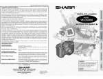
1
VE-CG30U
VE-CG40U
SERVICE MANUAL
S92Q8VE-CG30U
S72M7VL-MC500
DIGITAL STILL CAMERA
MODELS
VE-CG30U
VE-CG40U
In the interests of user-safety (Required by safety regulations in some countries) the set should be resrored to its
original condition and only parts identical to those specified
be used.
CONTENTS
Page
1. IMPORTANT SERVICE NOTES ........................................................................................................ 2
2. SPECIFICATIONS .............................................................................................................................. 4
3. PART NAMES .................................................................................................................................... 5
4. DISASSEMBLY OF THE SET ............................................................................................................ 6
5. TEST MODE FUNCTION ................................................................................................................... 9
6. TROUBLESHOOTING ...................................................................................................................... 19
7. BLOCK DIAGRAMS ......................................................................................................................... 24
8. SCHEMATIC DIAGRAMS ................................................................................................................ 30
9. SEMICONDUCTOR LEAD IDENTIFICATION ................................................................................. 64
10.PRINTED WIRING BOARD ASSEMBLIES ...................................................................................... 66
11.REPLACEMENT PARTS LIST / EXPLODED VIEWS ...................................................................... 72
12.PACKING OF THE SET ................................................................................................................... 82
SHARP CORPORATION
This document has been published to be used for after
sales service only.
The contents are subject to change wthout notice.
1
VE-CG30U
VE-CG40U
1. IMPORTANT SERVICE NOTES
connections, metal cabinet, screw heads, knobs and
control shafts, etc.) and measure the AC voltage drop
across the resistor. Reverse the AC plug (a non
polarized adaptor plug must be used but only for the
purpose of completing these checks) on the set and
repeat the AC voltage measurements for each exposed metallic part. Any reading of 0.45V rms (this
corresponds to 0.3mA rms AC.) or more is excessive
and indicates a potential shock hazard which must be
corrected before returning the video camera recorder
to the user.
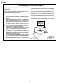
BEFORE RETURNING THE VIDEO CAMERA
RECORDER
Before returning the video camera recorder to the user,
perform the following safety checks.
1. Inspect all lead dress to make certain that leads are
not pinched or that hardware is not lodged between
the chassis and other metal parts in the video camera
recorder.
2. Inspect all protective devices such as non-metallic
control knobs, insulating materials, cabinet backs,
adjustment and compartment covers or shields, isolation resistor/capacitor networks, mechanical insulators etc.
3. To be sure that no shock hazard exists, check for
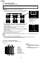
leakage current in the following manner.
· Plug the AC line cord directly into a 120 volt AC outlet
(Do not use an isolation transformer for this test).
· Using two clip leads, connect a l.5k ohm, 10 watt resistor
paralleled by a 0.15µF capacitor in series with all
exposed metal cabinet parts and a known ground,
such as a water pipe or conduit.
· Use a VTVM or VOM with 1000 ohm per volt, or higher
sensitivity or measure the AC voltage drop across the
resistor (See Diagram).
· Move the resistor connection to all exposed metal
parts having a return path to the chassis (antenna
VTVM
AC SCALE
1.5k ohms
10W
0.15 µF
TEST PROBE
TO EXPOSED
METAL PARTS
2
CONNECT TO
KNOWN EARTH
GROUND
VE-CG30U
VE-CG40U
■ PRECAUTIONS FOR USING LEAD-FREE SOLDER
1) Employing lead-free solder
"Main PWB", "Camera head PWB", "Audio I/O PWB", "Card PWB", "Inverter PWB", "Operation PWB", "DC Jack
PWB", "CCD PWB" of this model employs lead-free solder. The LF symbol indicates lead-free solder, and is attached
on the PWBs and service manuals. The alphabetical character following LF shows the type of lead-free solder.
Example:
Indicates lead-free solder of tin, silver and copper
2) Using lead-free solder
When fixing the PWB soldered with the lead-free solder, apply lead-free wire solder. Repairing with conventional
lead wire solder may cause damage or accident due to cracks.
As the melting point of lead-free solder (Sn-Ag-Cu) is higher than the lead wire solder by 40°C, we recommend you
to use a dedicated soldering bit. If you are not familiar with how to obtain lead-free solder or soldering bit, contact
our service station or service ranch in your area.
3) Soldering
As the melting point of lead-free solder (Sn-Ag-Cu) is 220°C which is higher than the conventional lead solder by
40°C, and as it has poor solderability, you may be apt to keep the soldering bit in contact with the PWB for extended
period of time. However, since the land may be peeled off or the maximum heat-resistance temperature of parts may
be exceeded, remove the bit from the PWB as soon as you confirm the steady soldering condition.
Lead-free solder contains more tin, and the end of the soldering bit may be easily corroded. Make sure to turn on
and off the power of the bit as required.
If a different type of solder stays on the tip of the soldering bit, it is alloyed with lead-free solder. Clean the bit after
every use of it.
When the tip of the soldering bit is blackened during use, file it with steel wool or fine sandpaper.
Lead-free wire solder for servicing
★
Description
Price Code
ZHNDAi123250E
J
φ0.3mm 250g(1roll)
BL
ZHNDAi126500E
J
φ0.6mm 500g(1roll)
BK
ZHNDAi12801KE
J
φ1.0mm
BM
Part No.
1kg(1roll)
3
VE-CG30U
VE-CG40U
2. SPECIFICATIONS
Digital still camera
Image Capturing Device
Operating Temperature
Storage Temperature
Operating Humidity
1/1.8" CCD image sensor (effective pixels: 4.04 megapixels(CG40U)
3.2megapixels(CG30U))
F2.0-F2.5 f=7-21mm (35mm film equivalent: 33-99mm)
1-3x in optical range, 3-9x in digital range
Auto white balance with daylight, fluorescent or tungsten
1.5" CGSilicon, 134,000pixels
AA size alkaline batteries
Ni-MH rechageble batteries
DC 6.0V with AC adapter
3.2W (CG40U), 2.9W (CG30U)
JPEG for still images
Motion JPEG for motion images (CG40U ONLY)
SD Memory Card
WAV (monaural) (CG40U ONLY)
4.5" x 2.9" x 2.4" (113.5 x 74.5 x 60 mm)
0.64lbs (290 g)(CG40U)(without batteries, card, wrist strap, and lens cap)
0.63lbs (285 g)(CG30U)(without batteries, card, wrist strap, and lens cap)
32°F to 104°F (0°C to +40°C)
-4°F to 140°F (-20°C to +60°C)
30% to 80%
Power Requirement
DC Output
Operating Temperature
Dimetions (W x H x D)
Weight
AC 100-120V, 50/60Hz
6V
32°F to 104°F (0°C to +40°C)
2.0" x 1.1" x 2.6" (50.0 x 27.0 x 65.5 mm)
0.24 lbs (108g)
Lens
Power zoom
Color Temperature Compensation
LCD monitor
Power Source
Power Consumption
Recording Format
Recording Medium
Sound Recording Format
Dimensions(W x H x D)
Weight
AC adapter
Specifications are sbject to change without notice.
SERVICE INFOMATION (FOR THE U.S.)
For the location of the nearest Sharp Authorized Service Center, or to obtain product literature, accessories,
supplies or customer assistance, please call 1-800-BE SHARP (1-800-237-4277) or visit SHARP's website
(http://www.sharpusa.com).
4
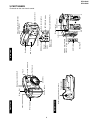
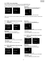
5
Tripod socket
Zoom lens
Flash sensor
Self timer indicator
Flash
Microphone (CG40 ONLY)
Shutter button
Mode Dial
Battery compartment door release
Bottom view
Wrist strap loop
Power button
Front view
DC IN jack
USB terminal
A/V OUT jack (CG40U)
VIDEO OUT jack (CG30U)
Flash /
Delete button
Macro /
Thumbnail
button
Speaker (CG40 ONLY)
SET/DISPLAY button
Data transfer button
Card slot cover
Power Zoom buttons (W: wide
angle,T: telephoto)
Diopter control
Status indicator
Jack cover
Operation button
MENU button
LCD screen
Viewfinder
Rear view
VE-CG30U
VE-CG40U
3. PART NAMES
For details on the use of each control.
VE-CG30U
VE-CG40U
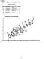
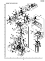
4. DISASSEMBLY OF THE SET
4-1. DISASSEMBLY OF THE SET
Note:
Before removing the cabinet, turn off the power supply, and ascertain that the battery have been removed.
1. Remove the five screws ((a)LX-HZ0063TAFF) and
two screws ((h)XiPSF17P04000).
4. After removing the one screw ((f)XiPSF17P03000)
and one screw ((g)XiPSN17P02000), disconnect
the connector and pull out the FFC to take out the
LCD unit.
a
h
FFC
LCD unit
h
a
a
a
a
2. Open the media lid and jack cover, and then open the
back cabinet turning it.
Jack cover
5. After removing the three screws ((f)XiPSF17P03000),
disconnect the connector and pull out the three
FFCs.
Pull out the CCD PWB slightly.
Back cabinet
FFC
Media lid
FFC
FFC
3. Disconnect the connector and pull out the FFC.
CCD PWB
FFC
Be sure to keep the media
lid open when attaching
the back cabinet ass'y.
6
VE-CG30U
VE-CG40U
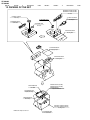
8. Remove the four screws ((f)XiPSF17P03000)
to take out the AV jack PWB and strobe unit.
6. Disconnect the two connectors to take out the CCD
PWB.
Each connector has four wires.
(For 40U, disconnect the three connectors.)
Caution:
Hold the transformer to remove the strobe unit.
Connector(CG40U only)
AV jack PWB
Connector
Connector
Transformer
CCD PWB
Strobe unit
7. Remove the one screw ((b)LX-HZ0050TAFF) and
disconnect the connector to take out the top cabinet.
Connector
b
Caution: Electric shock
When disassembling or repairing the set, do not touch the high voltage section of the main capacitor
since it contains high voltage. Be especially careful when removing and mounting the screws of the jack
unit (DUNTKB359PM) and strobe unit as well as when replacing the wires (QCNW-A562/564/565WJ).
After removing the strobe unit, prepare the following discharging jig (1) and connect it to the (2) position
as shown in the figure. Discharge main capacitor by leaving discharge jig attached for 60 seconds.
High voltage section
Clip
Clip connection
Prepare approx. 5kΩ/5W.
Figure 1
7
+
VE-CG30U
VE-CG40U
4-2. REPLACEMENT OF CCD SENSOR
4-2-1. BEFORE REPLACEMENT
1) The CCD image sensor is more sensitive to electrostatic breakage than C-MOS LSI.Therefore sufficient means
to prevent electrostatic damage must be taken when it is replaced.
• Ground the soldering iron.
• Ground also the human body, using the wrist strap(through an 1 M ohm resistor).
• Until the CCD sensor is mounted on the PWB, fit it to the conductive sponge, and short-circuit the foot lead.
2) Take utmost care so that the surface glass of CCD sensor and optical filter are not contaminated and damaged.
If any contamination is found, for example fingerprint, wipe it off with silicon paper or clean chamois skin.
3) When replacing the CCD sensor, use the static electricity prevention grounded soldering-iron, and perform
quickly soldering.
Index Mark
Index Mark
1
10
1
JAPAN
SHARP
RJ21P3
BA0PT
YYWWXX
20
10
JAPAN
SHARP
RJ21R3
BA0PT
YYWWXX
11
20
CG30
11
CG40
4-2-2. REMOVAL OF CCD
1) Unsolder the CCD sensor leads from the MAIN PWB.
2) Take out the MAIN PWB.
3) Remove the three screws (LX-HZ0013TAFF), and remove the sensor holder and CCD sensor.
4-2-3. MOUNTING OF CCD
1) Place the lens unit upright (since the CCD sensor mount ID faces upward, care must be taken so as not to
damage the front lens of unit), put the crystal filter first and then the dust protection rubber into the CCD holder
of lens unit.
Set the crystal unit with its thin side toward the lens unit.
2) Place the CCD sensor so that the its No. 1 pin is at the right lower (Positioning hole to be at right), and put the
CCD sensor into the CCD holder. For smooth and tight fitting, press the right lower part of back of CCD sensor,
and then press the left upper part.
Note: Pay attention to the direction of CCD sensor.
3) Place the sensor holder so that its two round markings be visible, and fix the sensor holder with the theree screws
(LX-HZ0013TAFF).
4) Mount the MAIN PWB so that the CCD sensor leads go thorough the PWB holes.
5) Solder the CCD sensor lead to the sensor PWB.
Note: Take care not to apply excessive heat.
Crystal
Rubber
*Refer to P.80
CCD
PFiLWA025WJZZ (CG40U)
PFiLWA026WJZZ (CG30U)
DUNTKB356QA00 (CG40U)
DUNTKB357QA00 (CG30U)
8
VE-CG30U
VE-CG40U
5.TEST MODE FUNCTION
[Note]: The meaning of TEST MODE FUNCTION Under this test mode, following things can be done.
1; Check and change EEPROM values, if required.
2; Apply several tests and adjustments.
3; Check the version # of firmware.
How to enter the test mode (TEST MODE initial screen)
Reset the user mode settings first. Download the user mode settings reset program to the SD card to create a test mode
setting card. Regarding Test Mode Setting Program("Shce0009.dat" & "Shcu0009.dat"), please refer to Service
Information. Insert this SD card for resetting the user mode settings in the camera and turn on the power while pressing
shutter. Then, "do you vertion up?; Do: Push Shutter, No: Do Not" appears on the CGS display. Next press shutter to
set the factory mode setting. (If it is not mecessary to reset the user mode setting, turn off the power and remove the
SD card.) The message changes to "vertion up start", and "version up complete" appears soon. After checking that
the power has turned on, turn it off and remove the SD card. Now restting the default settings is finished.
Shutter
Do You VersionUp?
3X
OPTICAL ZOOM
DIGITAL STILL
Do : Push Shutter
No : Do Not
Version Up Complete
Power Key
Set the camera to the factory mode in the following procedure.
1) Turn on the power by pressing the power key with the MENU key pressed down.
2) When entering the test mode, the screen on the right(TEST MODE initial screen)
or
key
TEST MODE initial screen
SET key
MENU Key
How to enter each test mode
MENU Key
1) Press the or
key to select the desired test mode.
Each time you press the or key, each test item is displayed.
Test Nos. and the corresponding test items are as follows.
TEST NOS.
Test item
TEST 0
EEPROM address change
TEST 1
LCD test pattern display
TEST 2
Default settings
TEST 3
White balance low color temp. adjustment
TEST 4
White balance high color temp. adjustment
TEST 5
CCD pixel defect correction
TEST 6
Not use in service
TEST 7
AF adjustment
TEST 8
Not use in service
TEST 9
Shutter timing adjustment (open side)
TEST A
Shutter timing adjustment (close side)
TEST B
Not use in service
TEST C
Not use in service
TEST D
Battery adjustment
TEST E
Not use in service
TEST F
Not use in service
2) If the desired test item is found, press the SET key to select it.
TEST MODE
BOOT VER xxxxx
IPL
VER xxxxx
MAIN VER xxxxx
SUB
VER xxxxx
USB
SNUM xxxxxxxx
0 CHANGE E2PROM
Display
0 CANGE E2PROM
1 TEST PATERN
2 SET SHIPPING
3 WB LOW TEMP
4 WB HIGH TEMP
5 DEFECT WHT BLK
6 DEFECT WHT BLK
7 FOCUS
8 CCD SENSITIVITY
9 SHUTTER OPEN
A SHUTTER CLOSE
B WB HIGH CALIB
C LCD POSITION
D BATTERY VOLTAGE
E WB LOW CALIB
F TEST F
[Note]: When finishing the service works, the camera must be set USER MODE again. In order to set the camera back
to USER MODE, execute TEST 2 written as "User mode settings" on page 11.
9
VE-CG30U
VE-CG40U
5-1. Test mode specifications
5-1-1. TEST 0: EEPROM address change
[Note]: If address is selected and the data is changed during adjustment, the data of EEPROM is rewritten,
so take sufficient care for operation and never fail to take a memo of the address and the data before changing
the data.
When entering the test mode 0, the screen on the right appears.
[Operation]
1. Move the triangle mark ( ) to the digit to be changed using the or button.
Then change the address value with the or button as desired.
ADDRESS
0000
ADDRESS
0000
ADDRESS
0000
VALUE
VALUE
VALUE
ADDRESS
0100
ADDRESS
0010
ADDRESS
0001
VALUE
VALUE
VALUE
ADDRESS
0000
VALUE
FF
01
0 CHANGE E2PROM
Set the address and press
the SET key.
( ) shifts to the value
change mode.
2. The value in the flash memory for the set address (upper line) and the initial
value (lower line) - if it has been set - are displayed under VALUE.
ADDRESS
Example: With the initial value 0, the upper line shows FF and the lower
0000
shows 01 at default.
3. When the address value is set, press the SET key to validate it.
VALUE
( ) shifts to the value change mode.
FF
4. As with the address value setting, change the value using the or and
or buttons.
5. When the value is set, press the SET key to validate it. ( ) shifts to the
01
address change mode.
0 CHANGE E2PROM
6. When changing other address values, repeat from step 1.
<<When displaying the battery adjustment value>>
The battery adjustment correction value may be displayed in negative. If so, “-” is displayed in front of the value
(0000).
[Exit]
When setting is complete, perform either operation below.
• To select another test mode: Press the DELETE key to return to the TEST MODE initial screen.
• To end the test mode: Press the power key to turn off the camera.
5-1-2. TEST 1: LCD test pattern display
When entering the test mode 1, the screen below appears.
Test pattern
[Operation]
Magenta White
Blue
Cyan
1: Color bar
2: BLACK
3: BLUE 10%
4: GREEN 50%
5: RED 30%
6: 50% WHITE
7: 30% WHITE
8: CROSS HATCH
9: 14 Steps Gray Scale
Red
Yellow
Green
Gray
10
• Press the or button to switch the test
pattern. See above for available test
patterns.
• Press the DELETE key to return to the
TEST MODE initial screen.
VE-CG30U
VE-CG40U
5-1-3. TEST 2: User mode settings
When finishing the service works, the camera must be set USER MODE again.
In order to set the camera back to USER MODE, execute TEST 2 as below.
[Operation]
Select the TEST 2 and press the SET key.
· Press the SET key start to [User Mode settings].
· When completed, the screen below appears.
TEST MODE
BOOT
VER
xxxxx
IPL
VER
xxxxx
MAIN
VER
xxxxx
SUB
VER
xxxxx
USB
SNUM xxxxxxxx
2 SET SHIPPING
TEST MODE 2 screen
COMPLETE
ENTER : START
DEL
: RETURN
00XX
00XX
0000
0000
0000
2 SET SHIPPING
After settng
DEL RETURN
2 SET SHIPPING
· Press the power key to end the test mode.
TEST 3,4,5,7,9,A and D are test modes for camera adjustment. See "5-2 Adjustment method" for detailed test
environment.
[Operation]
5-1-4. TEST 3: White balance low color temp.
adjustment
· Press the SET key to start adjustment.
· When completed, the screen below appears.
Select the TEST 3 and press the SET key.
COMPLETE
TEST MODE
BOOT
VER
xxxxx
IPL
VER
xxxxx
MAIN
VER
xxxxx
SUB
VER
xxxxx
USB
00XX
00XX
0000
0000
0000
ENTER : START
DEL
: RETURN
DEL RETURN
SNUM xxxxxxxx
3 WB LOW TEMP
TEST MODE 3 screen
4 WB HIGH TEMP
3 WB LOW TEMP
· To select another test mode:
Press the DELETE key to return to the TEST MODE
initial screen.
· To end the test mode:
Press the POWER key to turn off the camera.
After settng
[Operation]
· Press the SET key to start adjustment.
· When completed, the screen below appears.
COMPLETE
00XX
00XX
0000
0000
0000
5-1-6. TEST 5: CCD pixel defect correction.
adjustment
Select the TEST 5 and press the SET key.
DEL RETURN
3 WB LOW TEMP
TEST MODE
· To select another test mode:
Press the DELETE key to return to the TEST MODE
initial screen.
· To end the test mode:
Press the POWER key to turn off the camera.
BOOT
VER
xxxxx
IPL
VER
xxxxx
MAIN
VER
xxxxx
SUB
VER
xxxxx
USB
SNUM xxxxxxxx
5 DEFECT WHT BLK
TEST MODE 5 screen
COMPLETE
0XXX
0XXX
0XXX
0XXX
0XXX
TEST MODE
xxxxx
IPL
VER
xxxxx
MAIN
VER
xxxxx
SUB
VER
xxxxx
USB
SNUM xxxxxxxx
4 WB HIGH TEMP
TEST MODE 4 screen
After settng
· Press the SET key to start adjustment.
· When completed, the screen below appears.
Select the TEST 4 and press the SET key.
VER
5 DEFECT WHT BLK
[Operation]
5-1-5. TEST 4: White balance high color temp.
adjustment
BOOT
ENTER : START
DEL
: RETURN
ENTER : START
DEL
: RETURN
DEL RETURN
5 DEFECT WHT BLK
4 WB HIGH TEMP
· To select another test mode:
Press the DELETE key to return to the TEST MODE
initial screen.
· To end the test mode:
Press the POWER key to turn off the camera.
After settng
11
VE-CG30U
VE-CG40U
5-1-7. TEST 7: AF adjustment
5-1-9. TEST A: Shutter timing adjustment (open
side)
Select the TEST 7 and press the SET key.
Select the TEST A and press the SET key.
TEST MODE
BOOT
VER
xxxxx
IPL
VER
xxxxx
MAIN
VER
xxxxx
SUB
VER
xxxxx
USB
TEST MODE
ENTER : START
DEL
: RETURN
SNUM xxxxxxxx
7 FOCUS
BOOT
VER
xxxxx
IPL
VER
xxxxx
MAIN
VER
xxxxx
SUB
VER
xxxxx
USB
SNUM xxxxxxxx
7 FOCUS
TEST MODE 7 screen
A SHUTTER OPEN
After settng
TEST MODE A screen
ENTER : START
DEL
: RETURN
A SHUTTER OPEN
After settng
[Operation]
[Operation]
· Press the SET key to start adjustment.
· When completed, the screen below appears.
· Press the SET key to start adjustment.
· When completed, the screen below appears.
COMPLETE
COMPLETE
0XXX
0XXX
0XXX
0XXX
0XXX
0XXX
0XXX
0XXX
0XXX
0XXX
DEL RETURN
DEL RETURN
7 FOCUS
A SHUTTER OPEN
· To select another test mode:
Press the DELETE key to return to the TEST MODE
initial screen.
· To end the test mode:
Press the POWER key to turn off the camera.
· To select another test mode:
Press the DELETE key to return to the TEST MODE
initial screen.
· To end the test mode:
Press the POWER key to turn off the camera.
5-1-8. TEST 9: Shutter timing adjustment (close
side)
5-1-10. TEST D: Battery adjustment (open side)
Select the TEST D and press the SET key.
Select the TEST 9 and press the SET key.
TEST MODE
TEST MODE
BOOT
VER
xxxxx
IPL
VER
xxxxx
MAIN
VER
xxxxx
SUB
VER
xxxxx
USB
SNUM xxxxxxxx
9 SHUTTER CLOSE
TEST MODE 9 screen
ENTER : START
DEL
: RETURN
BOOT
VER
xxxxx
IPL
VER
xxxxx
MAIN
VER
xxxxx
SUB
VER
xxxxx
USB
SNUM xxxxxxxx
D BATTERY VOLTAGE
9 SHUTTER CLOSE
TEST MODE D screen
After settng
ENTER : START
DEL
: RETURN
D BATTERY VOLTAGE
After settng
[Operation]
[Operation]
· Press the SET key to start adjustment.
· When completed, the screen below appears.
· Press the SET key to start adjustment.
· When completed, the screen below appears.
COMPLETE
00XX
00XX
0000
0000
0000
COMPLETE
0XXX
0XXX
0XXX
0XXX
0XXX
DEL RETURN
D BATTRY VALTAGE
DEL RETURN
9 SHUTTER CLOSE
· To select another test mode:
Press the DELETE key to return to the TEST MODE
initial screen.
· To end the test mode:
Press the POWER key to turn off the camera.
· To select another test mode:
Press the DELETE key to return to the TEST MODE
initial screen.
· To end the test mode:
Press the POWER key to turn off the camera.
12
VE-CG30U
VE-CG40U
5-2. Adjustment method
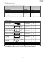
<Neccesary object of shooting, measuring instrument and jigs>
Jig name
Part code
AC adapter
UADP-A013WJZZ
2 halogen lamps
Commerical item
Gray scale chart
JiGCHART-1
Color Bar Chart
JiGCHART-4
Siemens star chart
JiGCHART-11
Illuminometer (0-3000 lux)
JiGMETER-1
Color temperature meter (1600 - 400000K)
JiGMETER-3
Color temperatute conversion filter (3200 - 6800K)
JiGHOYA-LB165
HOYA "LB-165"
Price code
AY
–
CP
DA
CE
CT
FF
BN
Remarks
<Extention Cable etc.>
Jig name
BATT.IN CHECK
Part code
Price code
QTANZA006WJZZ
AG
Shutter PWB - Main PWB
P=0.5mm
FFC
8 pin
QCNW-A561WJZZ
AB
Jack PWB - Main PWB *
&
Operation PWB - Main PWB
P=0.5mm
FFC
10 pin
QCNW-A563WJZZ
AC
Strobe Unit - Main PWB
P=0.5mm
FFC
15 pin
QCNW-A564WJZZ
AC
Jack PWB Main PWB
4 pin
Wire A'ssy
QCNW-A565WJZZ
AD
LCD I/F PWB Main PWB
P=0.5mm
FFC
18 pin
QCNW-A566WJZZ
AC
QCNWGA016WJZZ
QCNWGA017WJZZ
QCNWGA018WJPZ
AH
AH
AL
ø3.5 A/V Cable
ø3.5 Video Cable
USB Cable
* QCNW-A562WJZZ (P=0,5mm, FFC, 10 pin) is used for "Jack PWB - Main PWB" in production.
13
Remarks
14
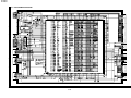
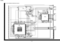
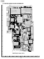
SC1002
QSOCN0672TAZZY
(reverse contact)
SC7201
QSOCN1872TAZZ
SC1803
QSOCN0672TAZZY
(reverse contact)
CGS IF PWB
Parts are monted on the back.
2
SC1801
QSOCN2472TAZZY
(reverse contact)
SC202
QSOCN0825TAN1Y
(reverse contact)
To:TOP(Shutter)
1
10 pin FFC
QCNW-A563WJZZ
OPE - MAIN
SC1001
QSOCN1672TAZZY
(reverse contact)
SC702
QSOCN1898TAZZY
(normal contact)
SC702
QSOCN1098TAZZY
(normal contact)
To: Operation
SC7201 TO:MAIN
QSOCN0871TAZZ
(normal contact)
P7201
QPLGN0276TAZZY
1mm pitch
(mounted on the back)
+
P2902
QPLGN0463TAZZY
1: GND
2: GND
3: VCC
4: VCC
SC1701
QSOCN1025TAN1Y
(reverse contact)
TO : MAIN
(mounted on the back)
P1701
QPLGN0276TAZZY
1 mm pitch
(mounted on the back)
1
2
1
2
1: GND
2: GND
3: VCC
4: VCC
SC3001 (STROBE)
QSOCN1507REN1Y
NON-ZIF Type
15 pin FFC
QCNW-A564WJZZ
STROBE - MAIN
SC401 (JACK)
QSOCN1007REN1
NON-ZIF Type
4 pin Wire
QCNW-A565WJZZ
Jack - MAIN
P2901 (DC-IN)
QPLGN0458REZZY
P1602 (MIC)
QPLGN0274TAZZY
2 1
Mic.
Speaker
VSPA016P-F18N
SC201 (SD Card)
QSOCZA035WJZZY
SC701
Do not care (Factory use)
QSOCN1007REN1
NON-ZIF Type
QTANZA006WJZZ
QSW-MA001WJZZY
—
1: GND
2: GND
3: VCC
4: VCC
normal contact
normal contact
reverse contact
SC4401
QSOCN1072TAZZY
TO : MAIN
(reverse contact)
1
10 pin FFC
QCNW-A562WJZZ
Jack - MAIN
P4401
QPLGN0463TAZZY
(mounted on the back)
QSOCN1571TAZZY
TO : MAIN
(normal contact)
(mounted on the back)
4
4: GND
3: GND
2: VCC
1: VCC
4: GND
3: GND
2: VCC
1: VCC
SC1802
QSOCN1872TAZZY
(reverse contact)
To: MAIN
18 pin FFC
QCNW-A566WJZZ
CGS IF - MAIN
8 pin FFC
QCNW-A561WJZZ
TOP - MAIN
RUNTKA028WJZZ
TEMP.DET.
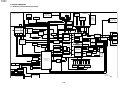
VE-CG30U
VE-CG40U
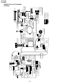
CONNECTOR LAYOUT DRAWING
VE-CG40U
15
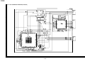
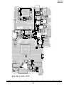
SC1002
QSOCN0672TAZZY
(reverse contact)
SC7201
QSOCN1872TAZZ
SC1803
QSOCN0672TAZZY
(reverse contact)
CGS IF PWB
Parts are monted on the back.
2
SC1801
QSOCN2472TAZZY
(reverse contact)
SC202
QSOCN0825TAN1Y
(reverse contact)
To:TOP(Shutter)
1
10 pin FFC
QCNW-A563WJZZ
OPE - MAIN
SC1001
QSOCN1672TAZZY
(reverse contact)
SC702
QSOCN1898TAZZY
(normal contact)
SC702
QSOCN1098TAZZY
(normal contact)
To: Operation
SC7201 TO:MAIN
QSOCN0871TAZZ
(normal contact)
P7201
QPLGN0276TAZZY
1mm pitch
(mounted on the back)
+
P2902
QPLGN0463TAZZY
1: GND
2: GND
3: VCC
4: VCC
SC1701
QSOCN1025TAN1Y
(reverse contact)
TO : MAIN
(mounted on the back)
SC201 (SD Card)
QSOCZA035WJZZY
SC701
Do not care (Factory use)
QSOCN1007REN1
NON-ZIF Type
QTANZA006WJZZ
QSW-MA001WJZZY
—
P2901 (DC-IN)
QPLGN0458REZZY
1: GND
2: GND
3: VCC
4: VCC
SC3001 (STROBE)
QSOCN1507REN1Y
NON-ZIF Type
15 pin FFC
QCNW-A564WJZZ
STROBE - MAIN
SC401 (JACK)
QSOCN1007REN1
NON-ZIF Type
4 pin Wire
QCNW-A565WJZZ
Jack - MAIN
1: GND
2: GND
3: VCC
4: VCC
normal contact
normal contact
reverse contact
SC4401
QSOCN1072TAZZY
TO : MAIN
(reverse contact)
1
10 pin FFC
QCNW-A562WJZZ
Jack - MAIN
P4401
QPLGN0463TAZZY
(mounted on the back)
QSOCN1571TAZZY
TO : MAIN
(normal contact)
(mounted on the back)
4
4: GND
3: GND
2: VCC
1: VCC
4: GND
3: GND
2: VCC
1: VCC
SC1802
QSOCN1872TAZZY
(reverse contact)
To: MAIN
18 pin FFC
QCNW-A566WJZZ
CGS IF - MAIN
8 pin FFC
QCNW-A561WJZZ
TOP - MAIN
RUNTKA028WJZZ
TEMP.DET.
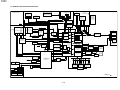
VE-CG30U
VE-CG40U
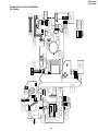
CONNECTOR LAYOUT DRAWING
VE-CG30U
VE-CG30U
VE-CG40U
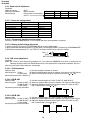
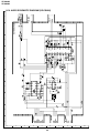
5-2-1. Power circuit adjustment
Conditions
Mode dial setting:
Measuring instrument:
Adjustment jig:
AUTO
Digital voltmeter
Dummy load is connected to
each TL.
Line name
LCD 12.0V
CAM 15.0V
CAM -7.0V
TL
TL5904
TL1
TL3
Current
8.6mA
10.0mA
8.0mA
Resistance
1.4KΩ
1.4KΩ
0.8KΩ
5-2-1-1. Power line voltage check
Power line name
1.APCON 5V
2.APCON 3.3V
3.DPCON 3.3V
4.DPCON 1.8V
5.LCD 12V
6.CAM 15V
7.CAM -7.0V
Measuring point (TL)
TL3901
TL4901
TL4902
TL6901
TP5903
TL5901
TL5902
Measured value
5.0±0.1V
3.3±0.1V
3.3±0.1V
1.8±0.1V
12.0±0.4V
15.0±0.5V
-7.0±0.35V
5-2-1-2. Temperature detection function check
Connect a resistor of 680Ω between TL770 and GND and check that the power is turned off.
5-2-1-3. Battery shutoff voltage adjustment
1) Connect the BTT.IN Check jig (QTANZA006WJZZ) to the main PWB P2902.
2) Apply 3.90±0.03V between the positive (+) and negative (-) electrodes of the BATT.IN Check jig (QTANZA006WJZZ).
3) According to the procedure of 5-1, set <TEST D> and press the SET key to adjust the voltage.
Long : (-)
Short : (+)
BATT.IN Check jig (QTANZA006WJZZ)
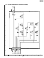
5-2-2. LCD circuit adjustment
Conditions
Mode: Set <TEST 0> according to the procedure of 5-1 and select the ADDRESS value which is specified in the
following adjustment items. Set E2PROM data to the value specified in the adjustment procedure. See 5-1-1.
Measuring instrument: Digital voltmeter, oscilloscope
5-2-2-1. VCO adjustment
Address: 0518
(1) Connect the digital voltmeter to TL1819.
Measuring point: TL1819
(2) Select the address 0518 and set the address. (No signal on the LCD Display)
TL1818 (GND)
(3) Set the data of the DC voltage to a specified value using or key.
Adjustment specification: 1.66V±0.1V
5-2-2-2. R-W/B ADJ
Address: 0501
(1) Connect the oscilloscope to TL1837 (G-OUT)/TL1838 (R-OUT).
Measuring point: TL1837 (G-OUT) (2) Select the address 0501 and set the address. (No signal on LCD Display)
TL1838 (R-OUT) (3) Adjust the difference between peak-to-peak values of TL1837 (G-OUT)
TL1832 (GND)
and TL1838 (R-OUT) using or key.
Adjustment specification: 0V±0.05V
G
R
5-2-2-3. B-W/B ADJ
Address: 0502
(1) Connect the oscilloscope to TL1837 (G-OUT)/TL1836 (B-OUT).
Measuring point: TL1837 (G-OUT) (2) Select the address 0502 and set the address. (No signal on LCD Display)
TL1836 (B-OUT) (3) Adjust the difference between peak-to-peak values of TL1837 (G-OUT)
TL1832 (GND)
and TL1838 (R-OUT) using or key.
Adjustment specification: 0V±0.05V
G
16
B
VE-CG30U
VE-CG40U
5-2-2-4. Common bias DC voltage adjustment
Address: 0509
Measuring point: TL1842
TL1832 (GND)
(1) Connect the digital voltmeter to TL1842.
(2) Select the address 0509 and set the address.
(Color Bar pattern appears onLCD Display)
(3) Set the data of the DC voltage to a specified value using
or
key.
Adjustment specification: 6.3V±0.1V
5-2-2-5. Video output level adjustment
Address: 0065
Measuring point: TL407
TL411 (GND)
(1) Connect the oscilloscope to TL407.(Video out; 75Ω termination)
(2) Select the address 0065 and set the address. (No signal on LCD Display)
(3) Set the level of H-SYNC to the adjustment specified value using or key.
Adjustment specification: 0.28V±0.01Vp-p
5-2-3. Camera circuit adjustment
• Preparation before adjustment and check items
(1) Illuminate the entire pattern evenly with luminance of approx. 2000 lux(In the white chart) (2 or more light sources
are recommended). Set the color temperature to 3200K.
(2) Use a new test pattern with no soil or color degradation.
(3) If defects are found in the electric circuit, identify the defective part using the measuring instrument and repair/
replace it before adjustment.
5-2-3-1. Focus infinity adjustment
[Purpose]
Focus point in each zoom position of the lens is memorized to correct the focus tracking position when operating
the zoom lens.
[Object]
Siemens Star Chart via the collimator or an object with simple and distinct outline.
If you do not have a collimator, perform adjustment while shooting an object with distinct outline from a long
distance.
Since the lens is automatically moved from Wide to Tele during adjustment, do not put an object in front of the
camera (do not shoot an object with a distinct outline when the lens is located at Wide).
[Procedure]
• After making the settings above, set <TEST 7> according to the procedures of 5-1 and execute it.
• Auto adjustment is performed.
Each optical zoom position is set, and the focus infinity position at that time is stored in memory.
• During adjustment, <EXECUTING> and the object are displayed on the LCD monitor.
• Data is collected while changing the zoom from Wide to Tele. Do not place any obstacles in front of the camera
until the adjustment is completed.
• If <OK> appears on the LCD monitor, adjustment is completed.
5-2-3-2. Adjustment for CCD pixel defect detection
[Purpose]
To memorize and correct the CCD imager’s white balance defect in the dark and black balance defect in the
brightness.
[Object]
An evenly illuminated white object under the lighting described in “Preparation before adjustment and check
items” (a light box can be used).
[Procedure]
• After making the settings above, set <TEST 5> according to the procedures of 5-1 and execute it.
• Auto adjustment is executed.
The lens is automatically shielded from the light and white balance in the dark is corrected.
Next, the aperture of the lens is automatically opened and black balance in the brightness is corrected while
a white object is shot.
• During adjustment, <EXECUTING> and the object appear on the LCD monitor.
• If <OK> appears on the LCD monitor, adjustment is completed.
17
VE-CG30U
VE-CG40U