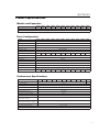
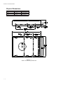
1
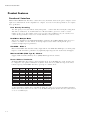
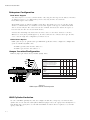
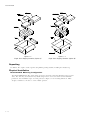
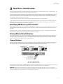
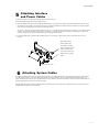
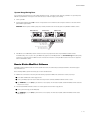
This document is a condensed version of the full Product Reference Manual. This version only includes the Maxtor Information about the Product. Information that can be found in the ANSI specification is not included in this document to reduce its over all size. Also eliminated are the Table of Contents and Glossary. This condensed version is created to allow faster downloading from Maxtor's Internet home page and MaxFax services. DiamondMax™ 2880 91152D8, 91008D7, 90845D6, 90840D6, 90720D5, 90648D5, 90576D4, 90510D4, 90432D3, 90288D2, 90256D2 Part #1390/A All material contained herein Copyright © 1998 Maxtor Corporation. DiamondMax™, DiamondMax™ 1280, DiamondMax™ 1750, DiamondMax™ 2160, DiamondMax™ 2880 and MaxFax™ are trademarks of Maxtor Corporation. No Quibble® Service is a registered trademark of Maxtor Corporation. Other brands or products are trademarks or registered trademarks of their respective holders. Contents and specifications subject to change without notice. All rights reserved. Printed in the U.S.A. 2/98 Corporate Headquarters 510 Cottonwood Drive Milpitas, California 95035 Tel: 408-432-1700 Fax: 408-432-4510 Research and Development Engineering Center 2190 Miller Drive Longmont, Colorado 80501 Tel: 303-651-6000 Fax: 303-678-2165 Revisions Manual No. 1390 REV EC NO. SECTION DESCRIPTION DATE A 78892B All Initial release. 3/10/98 Before You Begin Thank you for your interest in the Maxtor DiamondMax™ 2880 AT hard disk drives. This manual provides technical information for OEM engineers and systems integrators regarding the installation and use of DiamondMax hard drives Drive repair should be performed only at an authorized repair center. For repair information, contact the Maxtor Customer Service Center at 800-2MAXTOR or 408-432-1700. Before unpacking the hard drive, please review Sections 1 through 4. CAUTION Maxtor DiamondMax 2880 hard drives are precision products. Failure to follow these precautions and guidelines outlined here may lead to product failure, damage and invalidation of all warranties. 1 2 3 4 5 BEFORE unpacking or handling a drive, take all proper electro-static discharge (ESD) precautions, including personnel and equipment grounding. Stand-alone drives are sensitive to ESD damage. BEFORE removing drives from their packing material, allow them to reach room temperature. During handling, NEVER drop, jar, or bump a drive. Once a drive is removed from the Maxtor shipping container, IMMEDIATELY secure the drive through its mounting holes within a chassis. Otherwise, store the drive on a padded, grounded, antistatic surface. NEVER switch DC power onto the drive by plugging an electrically live DC source cable into the drive's connector. NEVER connect a live bus to the drive's interface connector. Please do not remove or cover up Maxtor factory-installed drive labels. They contain information required should the drive ever need repair. DIAMONDMAX 2880 – INTRODUCTION SECTION 1 Introduction Maxtor Corporation Maxtor Corporation has been providing high-quality computer storage products since 1982. Along the way, we’ve seen many changes in data storage needs. Not long ago, only a handful of specific users needed more than a couple hundred megabytes of storage. Today, downloading from the Internet and CD-ROMs, multimedia, networking and advanced office applications are driving storage needs even higher. Even home PC applications need capacities measured in gigabytes, not megabytes. Products Maxtor’s products meet those demanding storage capacity requirements with room to spare. They feature proven compatibility and reliability. While DiamondMax™ 2880 is the latest addition to our family of high performance desktop hard drives, the DiamondMax™ 2160 and DiamondMax™ 1750 series hard drives deliver industry-leading capacity, performance and value for many PC applications. Support No matter which capacity, all Maxtor hard drives are supported by our commitment to total customer satisfaction and our No Quibble® Service guarantee. One call – or a visit to our home page on the Internet (http://www.maxtor.com) – puts you in touch with either technical support or customer service. We’ll provide you the information you need quickly, accurately and in the form you prefer – a fax, a downloaded file or a conversation with a representative. Manual Organization This hard disk drive reference manual is organized in the following method: ❏ ❏ ❏ ❏ ❏ ❏ ❏ ❏ ❏ Section 1 Section 2 Section 3 Section 4 Section 5 Section 6 Section 7 Section 8 Appendix – Introduction – Description – Specifications – Installation – AT Interface – Host Software Interface – Interface Commands – Service and Support – Glossary Abbreviations A B B RV D E S C R I P T I O N ATA AT attachment bpi bits per inch C H S c y lin d e r - h e a d - s e c t o r d b d e c ib e ls dBA decibels, A weighted D M A d ir e c t m e m o r y a c c e s s ECC error correction code fci flux changes per inch G a c c e le r a t io n GB gigabyte H z h e rtz KB kilobyte LBA logical block address(ing) LSB least significant bit m A m illia m p e r e s 1–4 A B B RV D E S C R I P T I O N MB megabyte M b it s /s e c m e g a b it s p e r s e c o n d MB/sec megabytes per second M H z m e g a h e rtz m s m illis e c o n d M S B m o s t s ig n if ic a n t b it mV millivolts n s n an o se co n d s P IO p r o g r a m m e d in p u t /o u t p u t RPM revolutions per minute tpi tracks per inch U D M A u lt r a d ir e c t m e m o r y a c c e s s µ s e c m ic r o s e c o n d V volts W watts DIAMONDMAX 2880 – INTRODUCTION Conventions If there is a conflict between text and tables, the table shall be accepted as being correct. Key Words The names of abbreviations, commands, fields and acronyms used as signal names are in all uppercase type (e.g., IDENTIFY DRIVE). Fields containing only one bit are usually referred to as the “name” bit instead of the “name” field. Names of drive registers begin with a capital letter (e.g., Cylinder High register). Numbering Numbers that are not followed by a lowercase “b” or “h” are decimal values. Numbers that are followed by a lowercase “b” (e.g., 01b) are binary values. Numbers that are followed by a lowercase “h” (e.g., 3Ah) are hexadecimal values. Signal Conventions Signal names are shown in all uppercase type. All signals are either high active or low active signals. A dash character (-) at the end of a signal name indicates that the signal is low active. A low active signal is true when it is below ViL and is false when it is above ViH. A signal without a dash at the end indicates that the signal is high active. A high active signal is true when it is above ViH and is false when it is below ViL. When a signal is asserted, it means the signal is driven by an active circuit to its true state. When a signal is negated, it means the signal is driven by an active circuit to its false state. When a signal is released, it means the signal is not actively driven to any state. Some signals have bias circuitry that pull the signal to either a true or false state when no signal driver is actively asserting or negating the signal. These instances are noted under the description of the signal. 1–5 PRODUCT DESCRIPTION SECTION 2 Product Description Maxtor DiamondMax™ 2880 AT disk drives are 1-inch high, 3.5-inch diameter random access storage devices which incorporate an on-board ATA/Ultra DMA controller. High capacity is achieved by a balanced combination of high areal recording density and the latest data encoding and servo techniques. Maxtor's latest advancements in electronic packaging and integration methods have lowered the drive's power consumption and increased its reliability. Advanced magneto-resistive read/write heads, an state-of-the-art head/ disk assembly using an integrated motor/spindle design allow up to four disks in a 3.5-inch package. Exceptionally high data transfer rates and 9.0 ms access times make these performance series disk drives especially well-suited to high speed desktop and server applications. DiamondMax 2880 Key Features ANSI ATA-4 compliant PIO Mode 4 interface (Enhanced IDE) Supports Ultra DMA Mode 2 for up to 33 MB/sec data transfers 256 KB buffer with multi-adaptive cache manager 9.0 ms seek time Zone density and I.D.-less recording High reliability with > 500,000 hour MTBF Outstanding shock resistance at 200 Gs High durability with 50K constant start/stop cycles Advanced multi-burst on-the-fly Error Correction Code (ECC) Extended data integrity with ECC protected data and fault tolerant servo synchronization fields Supports EPA Energy Star Standards (Green PC Friendly) with ATA powering savings commands Auto park and lock actuator mechanism Low power consumption S.M.A.R.T. Capability Note: Maxtor defines one megabyte as 106 or one million bytes and one gigabyte as 109 or one billion bytes. 2–1 PRODUCT DESCRIPTION Product Features Functional / Interface Maxtor DiamondMax™ 2880 hard drives contain all necessary mechanical and electronic parts to interpret control signals and commands from an AT-compatible host computer. See Section 3 Product Specifications, for complete drive specifications. Zone Density Recording The disk capacity is increased with bit density management – common with Zone Density Recording. Each disk surface is divided into 16 circumferential zones. All tracks within a given zone contain a constant number of data sectors. The number of data sectors per track varies in different zones; the outermost zone contains the largest number of data sectors and the innermost contains the fewest. Read/Write Multiple Mode This mode is implemented per ANSI ATA/ATAPI-4 specification. Read/Write Multiple allows the host to transfer a set number of sectors without an interrupt request between them, reducing transfer process overhead and improving host performance. UltraDMA - Mode 2 Maxtor DiamondMax 2880 hard drives fully comply with the new ANSI Ultra DMA protocol, which greatly improves overall AT interface performance by significantly improving burst and sustained data throughput. Multi-word DMA (EISA Type B) - Mode 2 Supports multi-word Direct Memory Access (DMA) EISA Type B mode transfers. Sector Address Translation All DiamondMax 2880 drives feature a universal translate mode. In an AT/EISA-class system, the drive may be configured to any specified combination of cylinders, heads and sectors (within the range of the drive's formatted capacity). DiamondMax 2880 drives power-up in a translate mode: MODEL 91152D8 910 08D7 90845D6 90840D6 90720D5 90648D5 90576D4 90510D4 90432D3 90288D2 90256D2 CY L 22,332 19,540 16,383 16,276 13,957 12,555 11,166 9,925 8,374 5,583 4,960 HD 16 16 16 16 16 16 16 16 16 16 16 SPT 63 63 63 63 63 63 63 63 63 63 63 LZone (*) (*) (*) (*) (*) (*) (*) (*) (*) (*) (*) WPcom (*) (*) (*) (*) (*) (*) (*) (*) (*) (*) (*) C A PA C I T Y 11,520 MB 10,080 MB 8,455 M B 8,40 0 M B 7,20 0 MB 6,480 M B 5,760 MB 5,122 MB 4,320 M B 2,880 M B 2,560 M B (*) The fields LZone (Landing Zone) and WPcom (Write Pre-comp) are not used by the Maxtor hard drive and the values may be either 0 or the values set by the BIOS. All capacities listed in the above table are based on 106 or one million bytes. 2–2 PRODUCT DESCRIPTION Logical Block Addressing The Logical Block Address (LBA) mode can only be utilized in systems that support this form of translation. The cylinder, head and sector geometry of the drive, as presented to the host, differs from the actual physical geometry. The host AT computer may access a drive of set parameters: number of cylinders, heads and sectors per track, plus cylinder, head and sector addresses. However, the drive can’t use these host parameters directly because of zoned recording techniques. The drive translates the host parameters to a set of logical internal addresses for data access. The host drive geometry parameters are mapped into an LBA based on this formula: LBA where = (HSCA - 1) + HHDA x HSPT + HNHD x HSPT x HCYA = (HSCA - 1) + HSPT x (HHDA + HNHD x HCYA) HSCA = Host Sector Address, HHDA = Host Head Address HCYA = Host Cylinder Address, HNHD = Host Number of Heads HSPT = Host Sectors per Track (1) (2) The LBA is checked for violating the drive capacity. If it does not, the LBA is converted to physical drive cylinder, head and sector values. The physical address is then used to access or store the data on the disk and for other drive related operations. Defect Management Zone (DMZ) Each drive model has a fixed number of spare sectors per drive, all of which are located at the end of the drive. Upon detection of a bad sector that has been reassigned, the next sequential sector is used. For example, if sector 3 is flagged, data that would have been stored there is “pushed down” and recorded in sector 4. Sector 4 then effectively becomes sector 3, as sequential sectors are “pushed down” across the entire drive. The first spare sector makes up for the loss of sector 3, and so maintains the sequential order of data. This push down method assures maximum performance. On-the-Fly Hardware Error Correction Code (ECC) 33 bits, single burst, guaranteed Software ECC Correction 81 bits, single burst, guaranteed 33 bits, double bursts, guaranteed Automatic Park and Lock Operation Immediately following power down, dynamic braking of the spinning disks delays momentarily allowing the read/write heads to move to an inner mechanical stop. A small fixed magnet holds the rotary actuator in place as the disk spins down. The rotary actuator is released only when power is again applied. 2–3 PRODUCT DESCRIPTION Cache Management Buffer Segmentation The data buffer is organized into two segments: the data buffer and the micro controller scratch pad. The data buffer is dynamically allocated for read and write data depending on the commands received. A variable number of read and write buffers may exist at the same time. Read-Ahead Mode Normally, this mode is active. Following a read request, disk read-ahead begins on the first sector and continues sequentially until the allocated buffer is full. If a read request is received during the read-ahead operation, the buffer is examined to determine if the request is in the cache. If a cache hit occurs, readahead mode continues without interruption and the host transfer begins immediately. Automatic Write Reallocation (AWR) This feature is part of the write cache and reduces the risk of data loss during deferred write operations. If a disk error occurs during the disk write process, the disk task stops and the suspect sector is reallocated to a pool of alternate sectors located at the end of the drive. Following reallocation, the disk write task continues until it is complete. Write Cache Stacking Normally, this mode is active. Write cache mode accepts the host write data into the buffer until the buffer is full or the host transfer is complete. A command complete interrupt is generated at the end of the transfer. A disk write task begins to store the host data to disk. Host write commands continue to be accepted and data transferred to the buffer until either the write command stack is full or the data buffer is full. The drive may reorder write commands to optimize drive throughput. 2–4 PRODUCT DESCRIPTION Major HDA Components Drive Mechanism A brush-less DC direct drive motor rotates the spindle at 5,400 RPM (±0.1%). The dynamically balanced motor/spindle assembly ensures minimal mechanical run-out to the disks. A dynamic brake provides a fast stop to the spindle motor upon power removal. The speed tolerance includes motor performance and motor circuit tolerances. Rotary Actuator All DiamondMax™ 2880 drives employ a rotary voice coil actuator which consists of a moving coil, an actuator arm assembly and stationary magnets. The actuator moves on a low-mass, low-friction center shaft. The low friction contributes to fast access times and low power consumption. Read/Write Electronics An integrated circuit mounted within the sealed head disk assembly (near the read/write heads) provides up to eight head selection (depending on the model), read pre-amplification and write drive circuitry. Read/Write Heads and Media Low mass, low force magneto-resistive read/write heads record data on 3.5-inch diameter disks. Maxtor uses a sputtered thin film medium on all disks for DiamondMax 2880 drives. Air Filtration System All DiamondMax 2880 drives are assembled in a Class 100 controlled environment. Over the life of the drive, a 0.1 micron filter and breather filter located within the sealed head disk assembly (HDA) maintain a clean environment to the heads and disks. DiamondMax 2880 drives are designed to operate in a typical office environment with minimum environmental control. Microprocessor The microprocessor controls the following functions for the drive electronics: Command execution Cache management Data correction and error recovery Diagnostic execution Data sequencing Head positioning (including error recovery) Host interface Index detection Spin speed control Seeks Servo S.M.A.R.T. 2–5 PRODUCT DESCRIPTION Subsystem Configuration Dual Drive Support Two drives may be accessed via a common interface cable, using the same range of I/O addresses. The drives are jumpered as device 0 or 1 (Master/Slave), and are selected by the drive select bit in the Device/Head register of the task file. All Task File registers are written in parallel to both drives. The interface processor on each drive decides whether a command written to it should be executed; this depends on the type of command and which drive is selected. Only the drive selected executes the command and activates the data bus in response to host I/O reads; the drive not selected remains inactive. A master/slave relationship exists between the two drives: device 0 is the master and device 1 the slave. When J50 is closed (factory default, figure 2-1), the drive assumes the role of master; when open, the drive acts as a slave. In single drive configurations, J50 must be closed. Cable Select Option CSEL (cable select) is an optional feature per ANSI ATA specification. Drives configured in a multiple drive system are identified by CSEL’s value: – If CSEL is grounded, then the drive address is 0. – If CSEL is open, then the drive address is 1. Jumper Location/Configuration Darkened jumper pins indicate factory-installed (default) shunts. JUMPER CONFIGURATION Master/Slave Only drive in single drive system* Master drive in dual drive system* Slave drive in dual drive system C a b le S e le c t D is a b le d * E n a b le d 4092 Cylinder Limitation D is a b le d * E n a b le d J50 J48 J46 J44 J42 C C O O C O C Factor y Reser ved O Factor y Reser ved O Key * = Default C = Closed (jumper installed) O = Open (no jumper installed) Figure 2-1 PCBA Jumper Location and Configuration 4092 Cylinder Limitation On some older BIOS', primarily those that auto-configure the disk drive, a hang may occur when the drive cylinder value exceeds 4096. The 4092 Cylinder Limitation jumper reduces the capacity in the Identify Drive to 4092 allowing large capacity drives to work with older BIOS'. A software driver is required to access the full capacity of the drive. 2–6 PRODUCT SPECIFICATIONS SECTION 3 Product Specifications Models and Capacities M O DEL Formatted Capacity (MB LBA Mode) 91152D 8 91008D 7 90845D 6 90840D 6 90720D 5 90648D 5 90576D 4 90510D 4 90432D 3 90288D 2 90256D 2 11,520 10,080 8,455 8,400 7,200 6,480 5,760 5,122 4,320 2,880 2,560 90576D4 90510D4 90432D3 90288D2 90256D2 4 3 2 2 8,440,992 5,627,664 5,000,000 90432D3 90288D2 90256D2 Maxtor defines one megabyte as 106 or one million bytes and one gigabyte as 109 or one billion bytes. Drive Configuration MODEL 91152D8 91008D7 90845D6 90840D6 90720D5 Integrated Controller / Interface 90648D5 ATA-4 /EIDE Encoding Method EPR4 RLL 16/17 Interleave 1:1 Ser vo System Embedded Buffer Size / Type 256 KB SDRAM Data Zones per Surface Data Surfaces / Heads 16 8 7 6 6 Aerial Density 5 5 Tracks per Surface (Cylinders) 10,022 Track Density 9,800 tpi Flux Density 166-218 kfci Recording Density 156-205 kbpi Bytes per Sector / Block 512 Sectors per Track Sectors per Drive 4 2,000 Mb / in2 200-330 22,510,656 19,696,320 16,514,064 16,406,250 14,068,656 12,656,250 11,255,328 10,004,400 Performance Specifications M O DEL 91152D8 91008D7 90864D6 90840D6 90720D5 90640D5 90576D4 90525D4 Seek Times (typical)1 Track-to-track Average Maximum Average Latency Rotational Speed (±0.1%) Controller Command Overhead < 1.0 ms 9.0 ms < 18 ms 5.56 ms 5,400 RPM < 0.5 ms Data Transfer Rate To/from Interface (Ultra DMA - Mode 2) up to 33.0 MB/sec To/from Interface (PIO 4/Multi-word DMA - Mode 2) up to 16.7 MB/sec To/from Media up to 15.2 MB/sec Start Time (0 to Drive Ready) 1 9.0 sec typical Controller overhead not included 3–7 PRODUCT SPECIFICATIONS Physical Dimensions PARAMETER H e ig h t Length W id t h Weight STANDARD 1.02 inch 5.77 inches 4.02 inches 1.3 pounds M E T R IC 2 5 .9 m illim e t e r s 146.6 millimeters 102.1 millimeters 0 .5 9 k ilo g r a m s Figure 3 - 1 Outline and Mounting Dimensions 3–8 PRODUCT SPECIFICATIONS Power Requirements (Average) M ODE 12V ± 8% 5V ± 5% POWER Spin-up (peak) 1600 mA 200 mA 20.2 W Seek 620 mA 330 mA 9.0 W Read/Write 215 mA 350 mA 4.3 W Idle 4.1 W 245 mA 225 mA Standby 7 mA 245 mA 1.3 W Sleep 7 mA 140 mA 0.8 W Power Mode Definitions Spin-up The drive is spinning up following initial application of power and has not yet reached full speed. Seek A random access operation by the disk drive. Read/Write Data is being read from or written to the drive. Idle The drive is spinning, the actuator is parked and powered off and all other circuitry is powered on. The drive is capable of responding to read commands within 40 ms. Standby The spin motor is not spinning. The drive will leave this mode upon receipt of a command that requires disk access. The time-out value for this mode is programmable. The buffer is active to accept write data. Sleep This is the lowest power state – with the interface set to inactive. A software or hardware reset is required to return the drive to the Standby state. EPA Energy Star Compliance Maxtor Corporation supports the goals of the U.S. Environmental Protection Agency’s Energy Star program to reduce the electrical power consumption of computer equipment. Environmental Limits PARAMETER OPERATING NON-OPERATING/STORAGE Temperature 5° C to 55° C low temperature (-40° C) per MIL-STD-810E, method 502.3. high temperature (71° C) per MIL-STD-810E, method 501.3, climatic categor y; hot-induced conditions. Thermal Gradient 25° C per hour (maximum) Relative Humidity 5% to 95% (non-condensing) Wet Bulb 27° C (maximum) Altitude -200 to 10,000 feet (with any naturally occurring temperature and humidity rate within this range) Acoustic Noise (Idle mode) 36 dBA average sound power (per ISO 7779, 10 microphone) Per MIL-STD-810E, method 500.3, low pressure (altitude) test procedure I. storage; test condition 2, transport aircraft cargo compartment pressure. 3–9 PRODUCT SPECIFICATIONS Shock and Vibration PARAMETER OPERATING NON-OPERATING Mechanical Shock Random Vibration 20 Gs, 2.0 ms, no errors Per MIL-STD-810E, method 514.4, basic transportation, vertical axis PSD profile. 10 - 300 Hz at 0.004 G2/Hz 301 - 500 Hz at 0.0006 G2/Hz 200 Gs, 2.0 ms, no damage Swept Sine Vibration 5 - 20 Hz 21 - 300 Hz 10 Hz at 0.015 G2/Hz 40 Hz at 0.015 G2/Hz 500 Hz at 0.00015 G2/Hz 0.049 inches double amplitude 1.0 G peak amplitude (0 - peak) Reliability Specifications AFR < 1.7% MTBF > 500,000 hours Quality Acceptance Rate TBD (< 1,500 DPPM) Start/Stop Cycles 50,000 (minimum) Data Reliability < 1 per 1014 bits read Component Design Life 5 years (minimum) 3 – 10 The annualized average failure rate (AFR) applies to the period prior to the expiration of component design life, and is based on failures chargeable to Maxtor. Maxtor does not differentiate between various usage profiles (e.g., power-on hours, power saving modes, non-operating periods or operating temperatures within the published specification.) The quality acceptance rate indicates the percentage of Maxtor products successfully installed by our customers, and/or the number of defective parts per million (DPPM) encountered during the entire installation process. This indicates the minimum cycles for reliable start/stop function at a ≥ 60% confidence level. Data errors (non-recoverable). Average data error rate allowed with all error recovery features activated. Component design life is defined as a.) the time period before identified wear-out mechanisms impact the failure rate, or b.) the time period up to the wear-out point when useful component life expires. PRODUCT SPECIFICATIONS EMC/EMI Radiated Electromagnetic Field Emissions - EMC Compliance The hard disk drive mechanism is designed as a subassembly for installation into a suitable enclosure and is therefore not subject to Subpart J of Part 15 of FCC Rules (47CFR15) or the Canadian Department of Communications Radio Interference Regulations. Although not required, the disk mechanism has been tested within a suitable end-use product and found to comply with Class B limits of the FCC Rules and Regulations of the Canadian Department of Communications. The CE Marking indicates conformity with the European Union Low Voltage Directive (73/23/EEC) when the disk mechanism is installed in a typical personal computer. Maxtor recommends that testing and analysis for EMC compliance be performed with the disk mechanism installed within the user's end-use application. Canadian Emissions Statement This digital apparatus does not exceed the Class B limits for radio noise emissions from digital apparatus as set out in the radio interference regulations of the Canadian department of communications. Le present appareil numerique n'emet pas de bruit radioelectriques depassant les limites applicables aux appareils numeriques de Class B prescrites dans le reglement sur le brouillage radioelectrique edicte par le ministere des communications du Canada. Radiated Magnetic Field Emissions Minimum of VDE Class B and MIL-STD-461/462, Method RE01 (stand-alone test configuration). Radiated Electromagnetic Field Immunity IEC 801-3, Class 2 compliance. Radiated Magnetic Field Immunity Per MIL-STD-461/462, Method RD01(15 Hz to 100 kHz, stand-alone test configuration). Standard Test Methods Traditional hard drive specifications are open to incorrect interpretation, but internationally recognized standard test methods accurately measure how products perform in real-world conditions. These methods have gained worldwide acceptance since they reflect actual environments, have well-defined test requirements, are easily understood and provide repeatable results. They objectively demonstrate to our customers the reliable, durable design of Maxtor hard drives. Each international test specification provides the basic method and condition information needed for reference by a knowledgeable Test and Qualification Engineer. Acoustic specifications such as sound pressure are misleading because the test methods used are not controlled by recognizable standards. The sound pressure measurement itself is the least meaningful indicator of noise emissions as it relates to the human ear. The specification of sound power, loudness and sharpness are considered the most accurate acoustic measurement methodologies recognized by the leading acoustic measurement experts. ISO 7779, sound power, is a repeatable test method providing results reproducible in any properly equipped acoustic lab. Safety Regulatory Compliance All Maxtor DiamondMax™ 2880 drives comply with relevant product safety standards such as CE, CUL, TUV and UL rules and regulations. As delivered, DiamondMax 2880 hard disk drives are designed for system integration before they are used. 3 – 11 INSTALLATION SECTION 4 Handling and Installation Pre-formatted Drive This Maxtor hard drive has been formatted at the factory. Do not use a low-level formatting program. Important Notice There are a number of system BIOS’s currently in use which do not support hard drives with more than 4095 cylinders (2.1 gigabytes). This section contains information describing the conditions which may identify this limitation. In order to obtain the full capacity of your Maxtor drive, you will need to follow the recommended installation instructions. Hard Drive Handling Precautions ◆ During handling, NEVER drop, jar, or bump a drive. Handle the drive by its sides and avoid touching the printed circuit board assembly (PCBA). ◆ Hard drives are sensitive to electrostatic discharge (ESD) damage. Use proper ESD practices by grounding yourself and the computer system the hard drive will be installed in. ◆ Allow the hard drive to reach room temperature BEFORE installing it in your computer system. ◆ NEVER switch DC power onto the drive by plugging an electrically live DC source cable into the drive's connector. NEVER connect a live connector to the hard drive's IDE interface connector. Electro-Static Discharge (ESD) To avoid some of the problems associated with ESD, Maxtor advises that anyone handling a disk drive use a wrist strap with an attached wire connected to an earth ground. Failure to observe these precautions voids the product warranty. Manufacturers frequently experience “unsolved” component/hardware malfunctions often caused by ESD. To reduce the incidence of ESD-related problems, Maxtor recommends that any electronics manufacturing plans include a comprehensive ESD program, the basic elements and functions of which are outlined here: ESD Program Element Management Chief coordinator Multi-department committee Employee training ESD Program Function Institute and maintain Organize and enforce Evaluate and improve Educate and inform ESD program supplies typically include: wrist- and foot-worn grounding straps; counter-top and floor antistatic matting; wrist strap testers; ESD video and training materials. Sources for such supplies include: Static Control Systems – 3M 225-4S, 3M Center St. Paul, MN 55144 Charleswater 93 Border St. West Newton, MA 02165-9990 Maxtor also offers a complete video training package, “Care and Handling of Maxtor Disk Drives.” Contact your Maxtor representative for details. 4 – 12 INSTALLATION Unpacking and Inspection Retain any packing material for reuse. Inspect the shipping container for evidence of damage in transit. Notify the carrier immediately in case of damage to the shipping container. As they are removed, inspect drives for evidence of shipping damage or loose hardware. If a drive is damaged (and no container damage is evident), notify Maxtor immediately for drive disposition. Figure 4 - 1 Multi-pack Shipping Container 4 – 13 INSTALLATION Figure 4 - 2 Single Pack Shipping Container (Option A) Figure 4 - 3 Single Pack Shipping Container (Option B) Repacking If a Maxtor drive requires return, repack it using Maxtor packing materials, including the antistatic bag. Physical Installation Recommended Mounting Configuration The DiamondMax™ 2880 drive design allows greater shock tolerance than that afforded by larger, heavier drives. The drive may be mounted in any attitude using four size 6-32 screws with 1/8-inch maximum penetration and a maximum torque of 5-inch pounds. See Figure 3-1 for mounting dimensions. Allow adequate ventilation to the drive to ensure reliable operation. 4 – 14 INSTALLATION 1 Before You Begin IMPORTANT – PLEASE READ ! Please read this Installation Sheet completely before installing the Maxtor hard drive. It gives general information for installing a Maxtor hard drive in a typical computer system. If you don’t understand the installation steps, have a qualified computer technician install the hard drive. DO NOT use any low-level formatting software on this drive. Handling Precautions 쇵 Ꮬ Ꮬ Allow the hard drive to reach room temperature BEFORE installing it in your computer system. Hard drives are sensitive to electrostatic discharge (ESD) damage. Handle the drive by its sides. DO NOT touch the printed circuit board assembly. NEVER drop, jar, or bump the drive. DON’T connect/disconnect any drive cables when the power is on. Tools for Installation The following tools are needed to complete the installation of your Maxtor hard drive: ◆ A small (#2) Phillips head screw driver ◆ Small needle-nose pliers or tweezers ◆ Your computer user’s manual ◆ For drive capacities 8.4 GB or less, a DOS 5.0 (or higher) or Windows 95 bootable system diskette ◆ For drive capacities greater than 8.4 GB, a Windows 95 bootable system diskette Capacity Barriers Due to operating system limitations, DOS cannot access the full capacity of drives larger than 8.4 GB. The Microsoft Windows 95 operating system or equivalent (full installation), NOT a Windows 95 upgrade from DOS (Windows 3.1 or 3.11), is required to obtain the full capacity of any hard drive larger than 8.4 GB. Protecting Your Existing Data Have you backed up your hard disk? Periodic backup of important data is always a good idea. Whenever your computer is on, there is the potential for losing data on your hard drive. This is especially true when running disk utilities or any software that directly manipulates your files. Maxtor recommends that you make a backup copy of the files on any existing hard drives. If required, this data may then be copied to the Maxtor hard drive after it has been installed in your computer. Refer to your computer user’s manual for detailed data backup instructions. Capacity Calculations Maxtor defines one megabyte as 106 or one million bytes (1,000,000) and one gigabyte as 109 or one billion bytes (1,000,000,000). FDISK, CHKDSK, Windows, BIOS and hard drive manufacturers may show different capacity values for the hard drive as they use different methods and numbering systems to calculate hard drive capacities. The two most common numeric representations of the hard drive capacity are presented in the base 10 (decimal) and base 2 (binary) numbering systems. The formula to calculate the capacity of a drive is: Cylinders * Heads * Sectors * 512 This is a decimal number representing the total number of bytes (characters) that can be stored on the hard drive. To convert this number to binary megabytes (MB) or gigabytes (GB), this value must be divided by the decimal value of a binary MB or GB. The decimal equivalent of 1 MB (220) is 1,048,576 and 1 GB (230) is 1,073,741,824. Example for a 3.5 GB hard drive: 6,800 * 16 * 63 * 512 = 3,509,452,800 bytes or 3.5 GB using 106 or decimal values. The equivalent in binary MB is 3,509,452,800 / 1,048,576 = 3,346 MB. The equivalent in binary GB is 3,509,452,800 / 1,073,741,824 = 3,268 GB. 4 – 15 INSTALLATION 2 Hardware, Software and BIOS Requirements System Hardware Requirements Maxtor does not recommend installing drives greater than 8.4 GB in a 486 (50 MHz or slower), 286, 386 or older systems. These systems are not designed to support large capacity hard drives. Even if an EIDE interface card or drive management software are used the performance and reliability of the drive in older systems cannot be predicted. The minimum system recommended for drives 8.4 GB and less is a 486 DX 66 MHz system. For drives larger than 8.4 GB it is suggested that the minimum system be a Pentium class system. BIOS Requirements Most of the systems with newer BIOS; (typically with a date of July 1994 or newer) support large capacity drives. System BIOS dated prior to September 1997 do not provide support for drives greater than 8.4 GB. To obtain the full capacity of a drive larger than 8.4 GB either a BIOS upgrade, a BIOS enhancer card or the MaxBlast software (version 9.06M or newer) will be required to correctly support the drive. Ultra Direct Memory Access (UDMA) In order to utilize the drives UDMA mode it is required that the mother board or interface card have the full UDMA chip set and the UDMA drivers provided by the manufacturer installed on the system. If the mother board or interface card does not have this capability then UDMA will not be available on the drive IMPORTANT – Operating System Requirements for Drives Larger than 8.4 GB Due to limitations, DOS operating systems cannot access the full capacity of drives larger than 8.4 GB. The Windows 95 full installation operating system or equivalent – NOT a Windows 95 upgrade from DOS (Windows 3.1 or 3.11) – is required to obtain the full capacity of any hard drive larger than 8.4 GB. This means that the drive cannot be installed using a DOS operating system and then upgraded to Windows 95 or any subsequent release of this operating system, e.g. Windows 98. 4 – 16 INSTALLATION 3 Hard Drive Identification IDE stands for Integrated Drive Electronics and EIDE is Enhanced IDE. The IDE or EIDE interface is designed to support two devices – typically hard drives – on a single ribbon cable through one 40 pin connector on the mother board or interface card. Some mother boards and interface cards may have a second IDE/EIDE connector to support two additional IDE devices. The IDE/EIDE interface is identified as a primary or secondary interface. In systems with only a single connector on the mother board or interface card, it is the primary IDE/EIDE interface and requires a special interface card to add a secondary IDE/EIDE interface to the system. In systems with two connectors on the mother board or interface card, one is identified as the primary and the other as the secondary. The primary interface must be used for at least one IDE device before connecting any devices to the secondary IDE interface. The ribbon cable used is limited to a maximum length of 18 inches (per ANSI standards) and has two or three 40 pin connectors. This cable is referred to as a parallel cable and IDE devices may be connected any where on the cable. One of the connectors is attached to the IDE connector on the mother board or interface card and the remaining connector(s) are available for the IDE devices. Identifying IDE Devices on the Interface Each IDE interface (connector) supports one or two IDE devices on the ribbon cable. Each device must be identified as either the Master or Slave device on that interface (cable). Each cable must have a Master before it can have a Slave device on the cable. There cannot be two Master or two Slave devices on the same cable. IDE devices use jumpers to designate the Master/Slave identification of the device. Each manufacturer may have its own jumpering scheme to identify the device as a Master or Slave and its relationship to other IDE devices attached to the same cable. Primary/Master/Slave Definitions Some hard drive manufacturers use three definitions, Primary, Master and Slave. The manufacturers which use the three definitions define “Primary” as the only IDE device on the interface cable; “Master” as the 1st IDE device on the interface cable; and “Slave” as the 2nd device on the interface cable. Maxtor uses only two definitions that of Master and Slave devices on the IDE interface. Maxtor’s “Master” definition performs both the “Primary” and “Master” definitions used by other hard drive manufacturers with a single jumper setting. Jumper Settings A jumper is a small piece of plastic that slides over a pair of configuration pins on the drive to activate a specific function. The jumper illustration below shows three valid jumper settings for Maxtor hard drives – Master, Slave and Cable Select. Maxtor hard drives can be set as either a Master or a Slave device. There are no other jumpers to set when the Maxtor hard drive is installed on the same ribbon cable with another IDE device. Master Device Slave Device J50 J48 J46 J44 J42 Cable Select J50 J48 J46 J44 J42 EIDE Interface Connector J1 J50 J48 J46 J44 J42 Power Connector J2 J50 – Master/Slave J48 – Cable Select J46 – 4092 Cylinder Limitation J44 – Factory Reserved J42 – Factory Reserved Rear View of Maxtor Hard Drive Master, Slave and Cable Select Settings Before installing the drive in the computer, you must determine how the jumpers on the Maxtor hard drive are to be set for your system based upon the use of the Maxtor hard drive as either a Master or Slave device. Maxtor hard drives are shipped with the Master jumper setting enabled. IMPORTANT: If a Maxtor hard drive is being added to a system on the same cable with an existing IDE device, it may be necessary to re-configure the jumpers on the existing device to insure that the system will properly recognize both devices. Information regarding the correct jumper configurations on other IDE devices is available in their product documentation or from the manufacturer of that device. 4 – 17 INSTALLATION Systems Using Cable Select IMPORTANT – Most systems do not use this feature. Unless you are sure that your computer system supports Cable Select, do not set up the drive with this feature enabled. Maxtor hard drives support Cable Select. The Cable Select method of drive identification allows the system to identify Master and Slave IDE devices based upon the position (connector) the IDE device is attached to on the interface (ribbon) cable. A special IDE cable select interface (ribbon) cable is required for systems using the Cable Select feature. The ribbon cable included in Maxtor kits is a standard IDE cable and cannot be used in systems that use Cable Select. Systems that use Cable Select do not support the standard Master/Slave definitions described above and the standard IDE interface (ribbon) cable cannot be used on these systems. If your system supports this feature, refer to the system user’s manual or contact the system manufacturer for specific procedures for installing hard drives. On Maxtor DiamondMax 2880 hard drives, Cable Select is enabled by installing a jumper on J48. Relationship to Other IDE Devices IDE devices such as a CD-ROM or tape drive also have the jumper definitions for Master and Slave. The difference between a hard drive and these devices is that they require special software drivers in order to communicate properly with the system. Hard drives do not require additional drivers to communicate with the system. Because of limitations in the software drivers provided with CD-ROMs, tape drives and other IDE devices, Maxtor does NOT recommend that a hard drive be a slave to a CD-ROM or other IDE devices only to another hard drive. The software drivers for non hard drive IDE devices do not provide adequate support for communications to a hard drive as a slave device. Maxtor recommends that hard drives be the master to any other IDE devices except another hard drive. 4 Mounting Drive in System Turn the computer OFF, disconnect the power cord and remove the cover. Refer to the computer user’s manual for information on removing the cover. Each system manufacturer uses different types of cases, including desktop, mini-tower, full tower and other special configurations. As a result, there are many different possible mounting locations that could be used. In a typical system case, there are specific 3.5 inch and 5.25 inch bays available for storage devices. When a 3.5 inch mounting bay is available, mounting brackets and rails are not required. If a 5.25 inch mounting bay is used, mounting brackets (and possibly rails) will be required to mount the Maxtor hard drive in the system case. Refer to the system manufacturers user’s manual or contact the system manufacturer directly for additional information. NOTE: Some computer manufacturers have system cases that require custom mounting brackets and/or rails to physically mount a hard drive. If the ANSIstandard brackets and rails provided in the Maxtor Hard Drive Kit cannot be used in your system case, you will need to obtain custom brackets and rails from your system manufacturer. Installing 5.25-inch Mounting Brackets and Rails If the Maxtor hard drive is being mounted in a 5.25 inch drive bay, the following figure shows how to attach the brackets and/or rails to the drive. If the drive is being installed in a 3.5 inch bay which requires the use of rails, they may be installed directly on the drive without brackets. Installing in Drive Bay After the hard drive is prepared with mounting brackets/rails, if required, and the jumpers are set correctly, the drive can be mounted in a drive bay and secured. Note: The computer system the Maxtor hard drive is being installed in may use standard or a unique mounting and placement method. Refer to the computer user’s manual or contact the system manufacturer for detailed mounting instructions for that specific system. 4 – 18 INSTALLATION 5 Attaching Interface and Power Cables In order for the computer to recognize that the Maxtor hard drive is in the system, the power cable and IDE interface cable must be properly connected. 1 Attach an available IDE interface connector to J1 on the Maxtor hard drive. The connector on the cable provided with the Maxtor Hard Drive Kit is keyed and will only fit in one orientation. Do not force the connector. If the cable from the Maxtor kit is being connected to an IDE device or interface connection that is not keyed, the plastic plug in the connector at pin 20 may be removed. The striped or colored edge of the IDE interface cable indicates pin 1. Pin 1 on the IDE interface cable connector must match pin 1 on the drive IDE interface connector – closest to the drive power connector. It must also match pin 1 on the IDE connector on the mother board or IDE interface card. Refer to the system or interface card user’s manual for identification of pin 1 on their IDE interface connector. 2 Connect an available power connector to J2 on the Maxtor hard drive. This connector is keyed and will only fit in one orientation. Do not force the connector. After attaching the IDE interface cable and the power cable to the Maxtor hard drive, verify that all other cables connected to other devices, the mother board or interface cards are correctly seated. Striped/colored edge is pin 1 6 Attaching System Cables The computer system the Maxtor hard drive is being installed in will have its own cable placement and connection methodology, this means that the location of the IDE interface connectors on the mother board and/or interface card and the orientation of pin one is determined by the manufacturer. Also, older systems and interface cards may have only a single IDE interface connection, limiting the system to two IDE devices. Refer to the system or interface card user’s manual for detailed cable connection and orientation instructions. Attach the 40-pin IDE interface cable from the Maxtor hard drive to the IDE connector on the mother board or IDE interface card. Insure that the red edge of the ribbon cable is oriented to pin 1 on the interface. 4 – 19 INSTALLATION 7 System Setup The following procedures are designed for systems using the DOS 5.0 (or higher) or Windows 95 operating systems. For other operating systems (e.g., Windows NT®, OS2®, UNIX®, LINUX and Novell NetWare®), refer to the operating system user’s manual for the BIOS setting and other installation requirements. IMPORTANT: For drives with capacities larger than 8.4 GB the full installation set for Window 95a or 95b (OSR2) or equivalent is required. Operating systems that do not support extended interrupt 13 cannot access or format a drive larger than 8.4 GB. This is true regardless of BIOS, mother board or interface card support. DOS based operating systems do not support this interrupt and are limited to a maximum drive size that they can format and access of 8.4 GB. It is not possible to upgrade from a DOS operating system to Windows 95 or equivalent and obtain the full capacity of a drive larger than 8.4 GB. Setting the BIOS (CMOS) The SETUP (BIOS) program identifies the system configuration information (e.g., floppy disk drives, hard disk drives, video, etc.) used to identify devices attached to the computer during system boot. This includes the information about what kind and how many hard drives are attached to the system. IMPORTANT- Please Note: Major BIOS manufacturers like AMI, Award and Phoenix provide their core BIOS programs to system board manufacturers and OEM’s who have the capability of making modifications to some of the descriptions and definitions to meet their unique requirements. These changes include, but are not limited to, how to access the BIOS, the appearance of the information on the screens and the location of parameters within the BIOS. If you are unsure how to access the system BIOS refer to the system or BIOS manufacturers documentation or contact the system manufacturer for the correct procedure to enter the BIOS setup program for your system. System manufacturers like Compaq, IBM, AST etc., may use their own unique proprietary BIOS definitions and configurations and will have their own unique methods of accessing and setting their BIOS. If you have a system that utilizes such an unique BIOS refer to the system user’s manual or contact the manufacturer for assistance in accessing and setting the BIOS. WARNING: When entering the settings for the new Maxtor hard drive, be careful not to change any of the other BIOS settings, or other parts of the system may not work correctly. BIOS (CMOS) Parameters In order for the computer system to recognize the new Maxtor hard drive, it is necessary to set the system BIOS with the correct information about the hard drive. To do this, run the system SETUP (BIOS) program. The Maxtor hard drive must be identified to the system through the BIOS and it must be registered in the BIOS based upon its position relative to the other IDE devices connected to the system and recorded in the BIOS. Most newer BIOS’ provide the descriptions of Primary Master, Primary Slave, Secondary Master and Secondary Slave (see section 2) which identify the device configuration and location on an IDE interface and its relationship to the other IDE devices on the same interface or ribbon cable. Some older BIOS versions do not use this terminology for identification and it may be necessary to refer to the system user’s manual or BIOS documentation to determine where the drive settings should be set in that specific BIOS. If this information is not available, then it will be necessary to contact the system manufacturer for the correct terminology to correctly identify the drives within the system. The following are the typical steps to be used to set the hard drive parameters in a BIOS: A Turn the system ON. During the system start-up sequence, run the SETUP (BIOS) program or similar commands to access the system BIOS. Note: Newer systems will typically display a message (e.g., press DEL to Enter Setup) identifying how to access the SETUP (BIOS) program. B Once the SETUP (BIOS) program is active, do one of the following to set the BIOS parameters for the Maxtor hard drive. 1 Enter the BIOS menu where the hard drive definitions are displayed, select the correct entry (Primary Master, Primary Slave, Secondary Master or Secondary Slave or their equivalents) to set the parameters for the Maxtor hard drive. If the SETUP program provides an “AUTO DETECT” capability, use this feature to detect the Maxtor hard drive. If the SETUP program does not have AUTO DETECT, set the drive parameters as defined in 2 below. Typically, this feature is available for each individual IDE device. It may be necessary to exit the BIOS, re-boot the system and re-enter the BIOS before the AUTO DETECT operation will take effect. IMPORTANT After the SETUP program has detected the hard drive, verify that the Logical Block Addressing (LBA) mode is enabled for the drive - as not all BIOS versions set this feature during the AUTO DETECT process. 4 – 20 INSTALLATION Comment: When LBA is enabled, some BIOS programs (typically Award) will change the values of the cylinders and heads by dividing the cylinders by 2, 4, 8 or 16 and multiplying the heads by the same value. This operation will not change the capacity of the hard drive. If the system correctly detects the drive and does not hang during the boot process proceed to Section 9, If the system hung during the POST proceed to Section 8. If Auto Detect did not find the drive and no error message was presented proceed to step 2 below. 2 Enter the BIOS menu where the hard drive definitions are displayed and select the appropriate entry (Primary Master, Primary Slave, Secondary Master or Secondary Slave – or their equivalents) for the Maxtor hard drive. If the SETUP program does not provide an AUTO DETECT capability, the drive parameters must be set using the User Definable Type (UDT). Set the Cylinder, Head and Sector values with the values listed on the drive label. The drive label is located on the top cover of the drive. The fields LZone (Landing Zone) and WPcom (Write Pre-comp) are not used by the Maxtor hard drive. These values may be either 0 or the values set by the BIOS. Only the cylinder, head and sector values listed in the table must be entered. All other values may be zero (0). Set the LBA mode to enabled for this drive. Refer to the system user’s manual or contact the system manufacturer for information on enabling LBA. If the SETUP program does not provide the UDT, set the BIOS to the drive type with the largest capacity of those listed in the BIOS. C After the drive parameters are entered, follow the SETUP program procedures to save the settings and exit the SETUP program. After changing BIOS settings, saving the values and exiting, the SETUP program should force the system to re-boot. If you are not sure how the UDT is defined in the BIOS, refer to the computer user’s manual or contact the system manufacturer. Companies like Compaq, IBM and HP use their own unique definitions and setup procedures. 4 – 21 INSTALLATION 8 Hard Drive Preparation To finish the installation, the drive must be partitioned and formatted. Hard drive partitioning and formatting may be done with the operating system software or with MaxBlast installation software. Select A or B below to complete the preparation of the Maxtor hard drive. NOTE: Drive letter assignment is controlled by the operating system and not by the BIOS or MaxBlast. The operating system assigns drive letters to all devices as follows: (1) to all hard drives and their partitions; (2) to all other devices like CD-ROM’s and tape drives. When adding an additional hard drive to the system, the drive letters will be automatically changed by the operating system. A Preparing the hard drive using the operating system software. IMPORTANT Due to operating system limitations, DOS operating systems cannot access the full capacity of drives larger than 8.4 GB. The Windows 95 full installation, not an upgrade from DOS, operating system or equivalent is required to obtain the full capacity of any drive larger than 8.4 GB. If the system or interface card correctly supports the Maxtor hard drive, the drive may be partitioned and formatted using the operating system software. If the cylinder limitation jumper (J46) is installed or the BIOS does not support the hard drive, MaxBlast installation software must be used to prepare the hard drive. NOTE: All versions of DOS, PC-DOS, DR-DOS and Windows 95a (FAT 16 support) have a partition size limitation of 2.1 GB. For drives larger than 2.1 GB, the drive must be divided into partitions that do not exceed the 2.1 GB limitation. Windows 95b (OSR2) does not have this limitation. Windows NT®, OS2®, UNIX®, LINUX and Novell NetWare® should not have this limitation but please refer to their documentation or contact the manufacturer to verify their support or limitations. For detailed operating system installation assistance, refer to the system manufacturers user’s manual, the operating system user’s manual or contact the manufacturer directly. B Preparing the hard drive using MaxBlast installation software. 1 Boot the system with the bootable MaxBlast software installation diskette. 2 The MaxBlast installation software will load and the first screen of the program will display. Complete the information in the System Configuration Information table and follow the on-screen prompts to complete the hard drive installation. System/Drive Information The first time MaxBlast installation software is run, it will display information in a format similar to the System Configuration Information table below. Subsequent executions start at the main menu and allow the user to optionally display this information. SYSTEM /D RIV E IN FO RM A TIO N Maxtor Hard Disk Drive M odel Number S e r ia l N u m b e r Computer System Manufacturer M odel Processor (i.e., Pentium) S p e e d (i.e ., 9 0 M H z ) Interface Card Manufacturer M odel BIOS (CMOS/Setup) Manufacturer Version D a te Other Hard Disk Drive Manufacturer M odel BIOS Setting: Cylinders H e ad s SPT Other IDE Devices Type (i.e., CD-ROM) Manufacturer M odel The information in the System Configuration table must be completed for your records. This information will be requested by the Maxtor Technical Assistance representative in the event that you call for assistance. The Maxtor hard drive model number and serial number are also located on the top cover label of the hard drive. System information should be available in the computer users’s manual or in the documentation for the different devices attached to the system. Once the information in this table is copied from the screen, continue with the installation or exit the MaxBlast installation software as shown on the screen. EZMAX is a menu-driven program with on-line help to guide you through the installation process. 4 – 22 INSTALLATION System Hangs During Boot If the system hangs during the boot process after installing the Maxtor hard drive – either before or after setting the system BIOS – the system many have a BIOS with a cylinder limitation. This may occur for hard drives that exceed 2.1 GB. If this happens, do the following: 1 Turn the system OFF. 2 Install the cylinder limitation jumper (J46) on the drive. The figure below shows the Maxtor hard drive configured as a Master or Slave device with the cylinder limitation jumper installed. IMPORTANT: When the Cylinder Limitation jumper (J46) is installed, the Maxtor hard drive must be prepared using MaxBlast installation software. Master Device J50 J48 J46 J44 J42 Slave Device J50 J48 J46 J44 J42 EIDE Interface Connector J1 Cable Select J50 J48 J46 J44 J42 Power Connector J2 J50 – Master/Slave J48 – Cable Select J46 – 4092 Cylinder Limitation J44 – Factory Reserved J42 – Factory Reserved 3 If the BIOS was set to AUTO DETECT, follow the instructions in Section 7 to prepare the hard drive using the MaxBlast installation software. If other BIOS settings were used, access the system BIOS SETUP program and set the BIOS parameters to a User Definable Type with 4,092 cylinders, 16 heads and 63 sectors per track for the Maxtor hard drive. Then follow the instructions for setting the BIOS in Section 6 then Section 7 to prepare the hard drive with MaxBlast software. How to Obtain MaxBlast Software If a MaxBlast software installation diskette was not included with the hard drive, the software may be downloaded from Maxtor’s Internet home page at http://www.maxtor.com. After downloading MaxBlast, perform the following steps to create a bootable diskette: 1 If MaxBlast was downloaded to a hard drive, perform the following steps below. If MaxBlast was downloaded to a diskette, skip to step 2. ◆ Insert a blank 1.44 MB diskette in the A: floppy disk drive. ◆ Set the system DOS prompt to the hard drive letter and directory where the downloaded MaxBlast installation software is stored. ◆ Type “MAXBLAST,“ press the [Enter] key and follow the on-screen prompts. This will create a bootable diskette with MaxBlast software loaded and ready for use. Go to step 3. 2 If the downloaded MaxBlast installation software is on a diskette, place this diskette in the A: floppy disk drive. ◆ Set the system to the floppy disk drive DOS prompt. ◆ Type “MAXBLAST,“ press the [Enter] key and follow the on-screen prompts. This will create a bootable diskette with MaxBlast software loaded and ready for use. 4 – 23