1
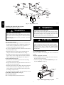
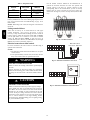
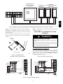
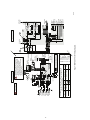
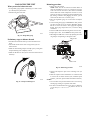
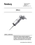
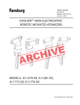
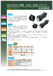
Heat Recovery Ventilator HRVXXSVU1157 Installation Instructions NOTE: Read the entire instruction manual before starting the installation. SAFETY CONSIDERATIONS Improper installation, adjustment, alteration, service, maintenance, or use can cause explosion, fire, electrical shock, or other conditions which may cause death, personal injury or property damage. Consult a qualified installer, service agency or your distributor or branch for information or assistance. The qualified installer or agency must use factory--authorized kits or accessories when modifying this product. Refer to the individual instructions packaged with the kits or accessories when installing. Follow all safety codes. Wear safety glasses, protective clothing, and work gloves. Have a fire extinguisher available. Read these instructions thoroughly and follow all warnings and cautions included in literature and attached to the unit. Consult local building codes and the current edition of the National Electrical Code (NEC) NFPA 70. In Canada, refer to the current editions of the Canadian Electrical Code CSA C22.1. A11189 HRVXXSVU1157 on Recognize safety information. When you see this symbol the unit and in instructions or manuals, be alert to the potential for personal injury. Understand the signal words DANGER, WARNING, and CAUTION. These words are used with the safety--alert symbol. DANGER identifies the most serious hazards, which will result in severe personal injury or death. WARNING signifies hazards, which could result in personal injury or death. CAUTION is used to identify unsafe practices, which may result in minor personal injury or product and property damage. NOTE is used to highlight suggestions which will result in enhanced installation, reliability, or operation. INTRODUCTION The Heat Recovery Ventilator (HRV) is used to exchange indoor stale air with outside fresh air. The HRV unit is equipped with a special heat recovery core which transfers sensible heat between the fresh incoming air and stale exhaust air. It is required to locate the HRV in a conditioned space. Special attention should be given to condensate drain, duct application, balancing the HRV, and locating unit for easy access and routine maintenance. The cross--flow design core allows entering and leaving air streams to transfer heat energy without mixing. LOCATION Inspect Equipment Move carton to final installation location. Remove the HRV from carton taking care not to damage unit. Remove all packaging and inspect unit for damage. Remove parts bag from inside unit. File claim with shipping company if shipment is damaged or incomplete. ! WARNING HRV PERSONAL INJURY, ELECTRIC PROPERTY DAMAGE HAZARD SHOCK ! OR CAUTION EQUIPMENT DAMAGE HAZARD Failure to follow this caution may result in equipment damage or improper operation. 1. To avoid premature clogged filters, turn OFF the unit during construction or renovation. 2. Please read specification label on product for further information and requirements. 3. Be sure to duct air outside – Do not intake/exhaust air into spaces within walls or ceiling or into attics, crawl spaces, or garage. 4. Intended for residential installation only in accordance with the requirements of NFPA 90B (for a unit installed in USA) or Part 9 of the National Building Code of Canada (for a unit installed in Canada). 5. Do not run any air ducts directly above or closer than 2--ft (0.61 m) to any furnace or its supply plenum, boiler, or other heat producing appliance. If a duct has to be connected to the furnace return plenum, it must be connected not closer than 9--ft 10--in (3 m) from this plenum connection to the furnace. 6. The ductwork is intended to be installed in compliance with all applicable codes. 7. When leaving the house for a long period of time (more than two weeks), a responsible person should regularly check if the unit operates adequately. 8. If the ductwork passes through an unconditioned space (e.g.: attic), the ducts must be insulated, and the unit must operate continuously except when performing maintenance and/or repair. Also, the ambient temperature of the house should never drop below 18_C (65_F). Failure to follow this warning could result in personal injury or death and property damage. 1. Use this unit only in the manner intended by the manufacturer. If you have questions, contact the manufacturer at the address or telephone number listed in the warranty. 2. We recommend that your unit be inspected by a specialized technician once a year. 3. Before servicing or cleaning the unit, disconnect power cord from electrical outlet. 4. This unit is not designed to provide combustion and/or dilution air for fuel--burning appliances. 5. When cutting or drilling into wall or ceiling, do not damage electrical wiring and other hidden utilities. 6. Do not use the units with any solid--state speed control device other than the corresponding ones listed in Table 1. 7. This unit must be grounded. The power supply cord has a 3--prong grounding plug for your personal safety. It must be plugged into a mating 3--prong grounding receptacle, grounded in accordance with the national electrical code and local codes and ordinances. Do not remove the ground prong. Do not use an extension cord. 8. Do not install in a cooking area or connect directly to any appliances. 9. Do not use to exhaust hazardous or explosive materials and vapors. 10. When performing installation, servicing or cleaning these units, it is recommended to wear safety glasses and gloves. 11. Due to the weight of the unit, two installers are recommended to perform installation. 12. When applicable local regulations comprise more restrictive installation and/or certification requirements, the aforementioned requirements prevail on those of this document and the installer agrees to conform to these at his own expenses. Table 1 – Solid State Speed Control Device UNIT CONTROL One Touch main wall control Standard main wall control HRVXXSUV11157 Basic main wall control 20 minute timer 60 minute crank timer 2 TECHNICAL DATA Air Distribution Stale air from building Fresh air from outside Stale Air to outside Stale air from building Filtered air to building HRV Fresh air to building A11190 A11191 Fig. 1 -- Normal Operation Fig. 2 -- Defrost or Recirculation Defrost Cycles HRVXXSVU1157 Outside Temperature Defrost Cycles (Minutes) Extended Defrost Cycles ( Minutes) _C Defrosting Operation Between Each Defrost Cycle Defrosting Operation Between Each Defrost Cycle 23 --5 7 25 9 23 14 --10 7 25 9 23 --17 --27 10 22 10 22 _F In a cold region (outside temperature ---17_F [---27_C] and lower), it may be necessary to setup EXTENDED DEFROST. See page 10. 23 9/16” (599 mm) 2 ¹/16” (53 mm) 3 13/16” (97 mm) 24 9/16” (624 mm) 7 7/16” (189 mm) 22 ½” (572 mm) 14 1/16” (358 mm) NOTE: Every port fits 6” round duct. 18 ¼” (464 mm) 14 15/16” (380 mm) A11192 Fig. 3 -- Dimensions HRVXXSVU1157 3 TYPICAL INSTALLATIONS Use the following illustrations as guidelines to help you decide on how the unit will be installed. All the units should be hung from the joists. If required, bathroom fans and a range hood may be used to exhaust stale air. Also, for homes with more than one level, we recommend one exhaust register at the highest level. There are 3 installation methods: Fully ducted, Central Draw Point and Simplified Installation. NOTE: An electrical outlet has to be available within 3--ft of the unit. Simplified Installation (Connection to a forced air system.) Stale air is exhausted to the outside. Fresh air from outside is filtered and supplied to the return (plenum) or the supply duct of the forced air unit. See Fig. 6. To avoid cross--contamination and achieve the highest efficiencies, the forced air system blower must always be ON. NOTE: Homes with multiple forced air systems should have one unit on each system. HRV Fully Ducted System (Primarily for homes with radiant hot water or electric baseboard heat.) Stale air coming from the registers located at the highest level of the house is exhausted to the outside. Fresh air from outside is filtered and supplied by the register located in the lowest liveable level. Homes with more than one level require at least one exhaust register at the highest level. See Fig. 4. A11195 Fig. 6 -- Simplified Installation INSTALLATION Inspect the contents of the box Inspect the exterior of the unit for shipping damage. Ensure that there is no damage to the door, ports, power cord, etc. Unit Door A11193 Fig. 4 -- Fully ducted system Central Draw Point (Connection to a forced air system.) Stale air coming from the registers located at the highest level of the house is exhausted to the outside. Fresh air from outside is filtered and supplied to the return (plenum) or the supply duct of the forced air unit. See Fig. 5. For this type of installation, it is not essential that the forced air system blower runs when the unit is in operation, but it is recommended. NOTE: Home with multiple forced air systems should have one unit on each system. HRVXXSVU1157 has one door. The unit door can be relocated on the back of the unit. This can be helpful to optimize duct configuration while keeping access for unit maintenance. To change door location, follow these steps (see Fig. 7): A. Remove both door lower mechanical screws no. 8--32 x 1--in (1) and set aside. B. Open (2) and lift out the door (3). To remove unit back panel, repeat steps A and B, but instead of removing 2 mechanical screws, there are 4 metal screws to be removed. Hang the door to the back of the unit and secure it by tightening its both lower mechanical screws. Hang back panel to the front of the unit and secure it by tightening its four metal screws. A B 3 2 1 A11196 A11194 Fig. 7 -- Hanging the door Fig. 5 -- Central Draw Point 4 Choose an appropriate location for the unit. S Within an area of the house where the ambient temperature is between 50_F (10_C) and 122_F (50_C) (basement, furnace room, closet, etc.). S Away from living areas (dining room, living room, bedroom), if possible. S So as to provide easy access to the interior of the unit, for maintenance. S Close to an exterior wall, so as to limit the length of the insulated flexible duct to and from the unit. S Away from hot chimneys and other fire hazards. S Allow for a power source (standard 3--prong grounding outlet). S Close to a drain. If no drain is close by, use a pail to collect run--off. Hang the unit with the four chains and springs provided. See Fig. 8. S If the house has two floors or more, be sure to plan for at least one exhaust register on the highest lived--in level. Calculating duct size Use Table 2 to ensure that the ducts you intend to install will be carrying air flows at or under the recommended values. Avoid installing ducts that will have to carry air flows near the maximum values and never install a duct if its air flow exceeds the maximum value. NOTE: Examples below use imperial units. The same calculation applies to metric units. A. Example of calculation: Problem: The installation requires two exhaust registers (one for the kitchen, and the other for the bathroom). The registers are connected to a main duct which will connect to the unit (high speed performance value of 140 cfm). What size of duct should be used for the main exhaust duct and for both end branches leading to the registers? (See Fig. 9.) Solution: Simplified method. (For a more detailed method of calculating duct size, refer to the ASHRAE or HRAI HANDBOOK.) Main duct: Table indicates for a 6--in ∅ duct: recommended air flow: 120 cfm, maximum air flow: 180 cfm. The 140 cfm high speed air flow is close enough to the recommended value (120) and far away enough from the maximum value (180). Therefore, a 6--in ∅ duct or larger is an appropriate choice for the main exhaust duct. End branches: Each end branch will have to transport a 70 cfm air flow (140 divided by 2). Table 2 indicates for a 5--in ∅ duct: recommended air flow: 75 cfm; maximum air flow: 110 cfm. The high speed air flow of 70 cfm is close enough to the recommended value (75) and far away enough from the maximum value (110). Therefore, a 5--in ∅ duct or larger is an appropriate choice for both end branches. NOTE: A 4--in ∅ duct would have been too small because the maximum acceptable value for a 4--in ∅ duct is 60 cfm. End branches 5-in ∅, 70 cfm A11197 Fig. 8 -- Chain spring installation ! CAUTION Main branch 6-in ∅, 140 cfm PROPERTY DAMAGE HAZARD Failure to follow this caution may result in property damage. Make sure the unit is level. Planning of the ductwork S Keep it simple. Plan for a minimum of bends and joints. S Keep the length of insulated ducts to a minimum. S Do not ventilate crawl spaces or cold rooms. Do not attempt to recover the exhaust air from a dryer or a range hood. This would cause clogging of the filters and recovery module. A11199 Fig. 9 -- Main exhaust leading to registers B. Fig. 10 is an example of a design for a fully ducted system with a unit having a high speed performance of 140 cfm. Table 2 – Ductwork Sizing Table DUCT DIAMETER RECOMMENDED AIR FLOW MAXIMUM AIR FLOW 4 inch (102 mm) round 40 CFM (19 L/S or 68 M3/H) 60 CFM (28 L/S or 102 M3/H) 5 inch (127 mm) round 75 CFM (35 L/S or 127 M3/H) 110 CFM (52 L/S or 187 M3/H) 6 inch (152 mm) round M3/H) 180 CFM (85 L/S or 306 M3/H) 120 CFM (57 L/S or 204 5 HRV Locating the unit 4-in 4-in 4-in 4-in 4-in 4-in ∅, 47 cfm 4-in ∅, 46 cfm 4-in 4-in 5-in 5-in ∅, 93 cfm 5-in ∅, 67 cfm 4-in ∅, 24 cfm 4-in ∅, 37 cfm 5-in ∅, 74 cfm 5-in ∅, 62 cfm 5-in 5-in 5-in 6-in 6-in ∅, 160 cfm 5-in ∅, 86 cfm 6-in ∅, 160 cfm HRV A11198 Fig. 10 -- Fully ducted system Installing the ductwork and registers ! Fully ducted system (see Fig. 4) ! WARNING PROPERTY DAMAGE HAZARD Failure to follow this warning could result in property damage. When performing duct connections, always use approved tools and materials. Respect all corresponding laws and safety regulations. Please refer to your local building code. PROPERTY DAMAGE HAZARD Failure to follow this warning could result in property damage. Never install a stale air exhaust register in a closed room where combustion device operates, such as a gas furnace, a gas water heater or a fireplace. ! Stale air exhaust ductwork S Install the stale air exhaust registers where the contaminants are produced: kitchen, living room, etc. Position the registers as far from the stairway as possible and in such a way that the air circulates in all the lived--in spaces in the house. S If a register is installed in the kitchen, it must be located at least 4 feet (1.2 m) from the range. S Install the registers 6 to 12 inches (152 to 305 mm) from the ceiling on an interior wall OR install them in the ceiling. S If possible, measure the velocity of the air flowing through the registers. If the velocity is higher than 400--ft/min (122 m/min), then the register type is too small. Replace with a larger one. Fresh air distribution ductwork S Install the fresh air distribution registers in bedrooms, dining rooms, living room and basement. S Keep in mind that the fresh air registers must be located as far as possible from the stale air registers. S Install the registers either in the ceiling or high on the walls with air flow directed towards the ceiling. (The cooler air will then cross the upper part of the room and mix with room air, before descending to occupant’s level.) S If a register must be floor installed, direct the airflow up the wall. WARNING CAUTION PROPERTY DAMAGE HAZARD Failure to follow this caution may result in property damage. When performing duct connections to the furnace supply duct, this duct must be sized to support the additional airflow produced by the unit. Also, the use of metal duct is highly recommended. Fresh air distribution ductwork There are 2 methods for connecting the unit to the furnace/air handler: Method 1: Supply side connection S Cut an opening into the furnace supply duct at least 18--in (0.5 m) from the furnace/air handler. S Connect this opening to the Fresh air distribution port of the unit (use metal duct, see Fig. 11). Metal duct Minimum 18-in (0.5m) Central Draw Point System (see Fig. 5) Stale air exhaust ductwork Same as for Fully Ducted System described above. A11200 Fig. 11 -- Main supply leading to registers 6 Stale air intake S Cut an opening into the furnace/air handler return duct not less than 10--ft (3.1 m) from the furnace/air handler (see Fig. 13) S Connect this opening to the Exhaust air from building port of the unit. Method 2: Return side connection S Cut an opening into the furnace return duct not less than 10--ft (3.1 m) from the furnace/air handler (A+B). S Connect this opening to the Fresh air distribution port of the unit (see Fig. 12). NOTE: For Method 2, it is not essential that the furnace/air handler runs when the unit is operation, but we recommend it. If desired, interlock (synchronize) the furnace/air handler blower operation (see page 11, ELECTRICAL CONNECTION TO FURNACE). Minimum 18-in (0.5 m) Metal duct B A A HRV S Make sure the unit duct forms an elbow inside the furnace/air handler ductwork. S If desired, interlock (synchronize) the furnace/air handler blower operation (see page 11, ELECTRICAL CONNECTION TO FURNACE). A+B = Not less than 10-ft (3.1 m) A11202 Fig. 13 -- Method 1: Supply--return connection Fresh air distribution S Same instructions as for Method 1 or Method 2. For Method 2 (Return--return), make sure there is a distance of at least 3--ft (0.9 m) between the 2 connections to the furnace/air handler. See Fig. 14. B A+B=Not less than 10-ft (3.1m) A11201 A Fig. 12 -- Return side connection Simplified installation ! B WARNING Minimum 3-ft (0.9 m) A+B = Not less than 10-ft (3.1 m) PROPERTY DAMAGE HAZARD A11203 Fig. 14 -- Method 2: Return--return connection Failure to follow this warning could result in property damage. When performing duct connections, always use approved tools and materials. Respect all corresponding laws and safety regulations. Please refer to your local building code. ! CAUTION PROPERTY DAMAGE HAZARD ! Failure to follow this caution may result in property damage. CAUTION If using Method 2, make sure the furnace/air handler blower operation is synchronized with the unit operation. See page 11, ELECTRICAL CONNECTION TO THE FURNACE. PROPERTY DAMAGE HAZARD Failure to follow this caution may result in property damage. When performing duct connections to the furnace supply duct, this duct must be sized to support the additional airflow produced by the unit. Also, the use of metal duct is highly recommended. For a Return--Return installation, the furnace blower must be in operation when the unit is in operation. NOTE: For Method 1, it is not essential to synchronize the furnace blower operation with the unit operation, but it is recommended. There are 2 methods for connecting the unit to the furnace/air handler. 7 Connecting the ducts to the unit barrier using the port strap (included in unit parts bag). To do so, insert one collar pin through vapor barrier and first strap hole, then insert the other collar pin through vapor barrier and center strap hole and close the loop by inserting the first collar pin in the last strap hole. Insulated flexible ducts Use the following procedure to connect the insulated flexible ducts to the ports of the unit (Exhaust air to outside and Fresh air from outside ports). ! ! CAUTION PROPERTY DAMAGE HAZARD PROPERTY DAMAGE HAZARD Failure to follow this caution may result in property damage. Failure to follow this caution may result in property damage. Make sure the vapor barrier on the insulated ducts does not tear during installation to avoid condensation within the ducts. If ducts have to go through an unconditioned space (e.g.: attic), always use insulated ducts. HRV CAUTION 1. Pull back the insulation to expose the flexible duct. 2. Attach the flexible duct to the port using tie wrap. 3. Pull the insulation over the joint and tuck in between the inner and outer rings of the double collar. 4. Pull down the vapor barrier (shaded part in Fig. 15) over the outer ring to cover it completely. Fasten in place the vapor Non--insulated rigid ducts Use metal screws and duct tape to connect the rigid ducts to the unit ports. Non--insulated flexible ducts Use tie wraps to connect the flexible ducts to the unit ports. 2 1 4 3 Collar pin Collar pin A11204 Fig. 15 -- Ductwork installation Non-insulated rigid ducts Non-insulated flexible ducts A11205 Fig. 16 -- Ductwork installation 8 INSTALLING TWO EXTERIOR HOODS Choose an appropriate location to install the exterior hoods: S There must be a minimum distance of 6--ft (1.8 m) between the hoods to avoid cross--contamination S There must be a minimum distance of 18--in (457 mm) from the ground Make a water trap loop in the tube to prevent the unit from drawing unpleasant odors from the drain source. Make sure this loop is located OVER the “T” as shown. Run the tube to the floor drain or to an alternative drain pipe or pail. IMPORTANT: If using a pail to collect water, locate the tube end approximately 1--in (25 mm) from the top of the pail in order to prevent water from being drawn back up into the unit. Make sure the intake hood is at least 6 feet (1.8 m) away from the following: S Dryer exhaust, high efficiency furnace vent, central vacuum vent S Gas meter exhaust, gas barbecue grill S Any exhaust from a combustion source S Garbage bin and any other sources of contamination Refer to figure beside for connecting insulated ducts to the exterior hoods. An “Anti--gust intake hood’’ should be installed in regions where a lot of snow is expected to fall. HRV ± 1” Exhaust hood A11209 Intake hood 18-in (457 mm) Fig. 19 -- Drain connection 6-ft (1.8 m) CONTROLS 6-ft (1.8 m) This unit is equipped with an integrated control located under the unit, on the recessed side of electrical compartment. Plug the unit. Unit booting sequence Optional duct location 18-in (457 mm) Tape and duct tie A11206 Fig. 17 -- Exterior hoods The unit booting sequence is similar to a personal computer boot sequence. Each time the unit is plugged in after being unplugged, or after a power failure, the unit will perform a 30--second booting sequence before starting to operate. During the booting sequence, the integrated control LED will light GREEN (unit set in normal defrost) or AMBER (unit set in extended defrost) for 5 seconds, and then will shut off for 2 seconds. After that, the LED will light RED for the rest of the booting sequence. During this RED light phase, the unit is checking and resetting the motorized damper position. Once the motorized damper position completely set, the RED light turns off and the booting sequence is done. NOTE: No command will be taken until the unit is fully booted. Integrated control Connecting the drain Cut 2 sections of the plastic tube, at least 16--in (406 mm) long, and attach them to each inner drain fitting, located under the unit. Join both short sections to the “T” junction and main tube as shown in Fig. 18. Use the push button (1) to control the unit. The LED (2) will then show on which mode the unit is in. See Fig. 20. 2 1 16" (406 mm) 16" (406 mm) Bottom of the unit A11210 Fig. 20 -- Integrated control A11208 Fig. 18 -- Drain connection Refer to Table 3 to see how to operate the unit using its integrated control. 9 Table 3 – Integrated control PRESS ON PUSH BUTTON LED COLOR RESULTS Once Amber Unit is on low speed Twice Green Unit is on high speed Three Times No Light Unit is Off Use the terminal connector included in the installation kit to perform the electrical connection for main and optional wall controls. Check if all wires are correctly inserted in their corresponding holes in the terminal block. (A wire is correctly inserted when its orange receptacle is lower than another one without wire. See Fig. 21, wire A is correctly inserted, but wire B is not.) 1 If a problem occurs during the unit operation, its integrated control LED (2) will blink. The color of the blinking light depends on the type of error detected. Refer to Troubleshooting on page 15 for further details. NOTE: When using main control, the integrated control must be turned off. 2 HRV Setting extended defrost These units are factory set to normal defrost. In cold region (outside temperature --17_F [--27_C] and lower), it may be necessary to setup extended defrost. During the first 2 seconds of booting sequence, while the integrated control LED is GREEN, press on push button for 3 seconds to set the unit in extended defrost; the LED will blink AMBER to show the unit is in extended defrost mode. After that, the LED will shut off, then light RED (the unit returns in its booting sequence). B A A11211 Fig. 21 -- Terminal connector Electrical connection to main controls For more convenience, this unit can also be controlled using an optional main wall control. NOTES: 1. The integrated control must be turned OFF to use an optional main control. 2. If an optional auxiliary control is used, if activated, this auxiliary control will override the optional main control. ! NO C NC I OC OL Y R G B Y WARNING G B Main wall control One Touch - Rear view OC G B A11212 Fig. 22 -- Electrical connection to One touch ELECTRICAL OPERATION HAZARD Failure to follow this warning could result in personal injury or death. Always disconnect the unit before making any connections. Failure in disconnecting power could result in electrical shock or damage of the wall control or electronic module inside the unit. ! NO C NC I OC OL Y R G B CAUTION PROPERTY DAMAGE HAZARD A11213 Fig. 23 -- Electrical connection to main wall control Failure to follow this caution may result in property damage. Never install more than one optional main wall control per unit. Make sure that the wires do not short--circuit between themselves or by touching any other components on the wall control. Avoid poor wiring connections. To reduce electrical interference (noise) potential, do not run wall control wiring next to control contactors or near light dimming circuits, electrical motors, dwelling/building power or lighting wiring, or power distribution panel. 10 DEHUMIDISTAT or HUMIDITY CONTROL (OPTIONAL) 20-MINUTE 60-MINUTE PUSH-BUTTON SWITCHES CRANK TIMER (5 MAXIMUM) HRV NO C NC I OC OL Y R G B A11214 Fig. 24 -- Electrical connection to dehumidistat, 20--minute lighted push button timer or 60--minute crank timer NOTE: If an optional auxiliary control is activated and then, the Dehumidistat (or Humidity Control) is being activated, the Dehumidistat (or Humidity Control) will override the auxiliary control commands. Once the control(s) connections have been made, insert the terminal connector on the recessed side of electrical compartment. See Fig. 25. NOTE: For information about the operation of the wall controls, refer to the user guide. ELECTRICAL CONNECTION TO THE FURNACE WARNING ! Terminal connector ELECTRICAL OPERATION HAZARD Failure to follow this warning could result in personal injury or death. Never connect a 120--volt AC circuit to the terminals of the furnace interlock (standard wiring). Only use the low voltage class 2 circuit of the furnace blower control Bottom of the unit A11219 Fig. 25 -- Terminal connector For a furnace connected to a cooling system: On some older thermostats, energizing the “R” and “G” terminals at the furnace has the effect of energizing “Y” at the thermostat and thereby turning on the cooling system. If you identify this type of thermostat, you must use the ALTERNATE FURNACE INTERLOCK WIRING. See Fig. 26. Standard furnace interlock wiring THERMOSTAT TERMINALS FOUR WIRES TWO WIRES heating only W R G W 4 WIRES G Y THERMOSTAT TERMINAL 2 WIRES heating only wiring nuts W RR NO NC G C C C YY Y FURNACE 24-VOLT TERMINAL BLOCK R UNIT TERMINAL CONNECTOR Y NO C NC I OC OL Y R G B G UNIT TERMINAL CONNECTOR R NO C NC I OC OL Y R G B W Alternate furnace interlock wiring FURNACE 24-VOLT TERMINAL BLOCK TWO WIRES 2 WIRES COOLING SYSTEM COOLING SYSTEM A11215 Fig. 26 -- Electrical connection to furnace 11 G B B B B B B BN BN BL BL Ref 1 J9 MED HI 3 2 1 54321 J8 W G B 2 1 See note413 2 1 2 1 1 2 F1 J10 3 1 2 3 2 1 BN Y Y BN 24 V class 2 9.5 V class 2 120 V, 60 Hz W1 J4 J7 J6 J5 nc nc P 83 V BL R 68 V 62 V neutral W B T1 J11 REF 1 ORG 3 2 1 ORG to ORG ORG to ORG RED to RED REF2 3 2 1 REF 1 RED RED to RED Factory shipped J1 R1 Override switch (optional; see notes 3 & 4) B GR Y Field wiring remote control (see notes 3 & 4) t˚ Defrost temperature sensor DAMPER ELECTRONIC ASSEMBLY 140 MED-HI (100V) & LO (62V) HI LO 120 V 100 V 83 V 68 V 62 V neutral R MED BL MED-LO P O MED-HI B Ref 1 24 V class 2 9.5 V class 2 R O Fig. 27 -- HRVXXSVU1157 wiring diagram 160 CFM MAX COLOR CODE B BLACK BL BLUE BN BROWN G GREEN O ORANGE P PURPLE R RED W WHITE Y YELLOW nc no connection Line voltage factory wiring Class 2 low voltage factory wiring Class 2 low voltage field wiring ELECTRONIC Furnace blower interlock ASSEMBLY A1 J14-1: NO J14-2: COM J14-3: nc (optional; see notes 3 & 5) HI (120V) & LO (62V) FAN SPEEDS 21 A2 10 9 J13 8 7 6 5 ICP 4 J12 3 2 12345 1 Ref J14 2 12 J2 12 54321 J3 FAN MOTORS SPEED SELECTION CAUTION: You can change REF 1 or REF 2, but not both at the same time. If you do change REF 1 and REF 2 you will inverse fan motor speeds. Supply fan M2 motor Exhaust fan motor M1 Exhaust fan motor C1 capacitor Supply fan motor C2 capacitor G O 120 V 100 V B Damper motor M3 B NOTES 1. Use specified UL listed/CSA Certified line fuse. 2. If any of the original wire, as supplied, must be replaced, use the same equivalent wire. 3. Field wiring must comply with applicable codes, ordinances and regulations. 4. Remote controls (class 2 circuit) available, see instruction manual. 5. Furnace fan circuit must be class 2 circuit only. WIRING DIAGRAM JU1 Critical characteristic. JU1 JU1 12 J8-5 J8-1 J8-2 J8-4 J9-4 J9-1 J9-2 J9-3 F1 CPU K2 1 23 K3 K1 K5 K4 K2 JU1 J10-2 HI MED 120 V, 60Hz Line J11-2 J11-1 J12-5 J12-4 K4 J12-3 J12-2 J12-1 K3 K1 Ref 2 LOGIC DIAGRAM J5-2 J2-5 J2-4 J2-3 J2-2 J2-1 J6-2 J6-1 J14-4 J14-5 J14-6 J14-7 J14-8 J14-9 J14-10 J14-2 J14-1 J14-3 J3-2 J3-1 A2 Override switch (optional; see notes 3, 4) Field wiring remote control (see notes 3, 4) Furnace blower interlock (optional; see notes 3, 5) Damper motor Supply fan motor capacitor J4-2 Supply fan motor J4-1 J4-3 Exhaust fan motor capacitor J7-2 J7-1 K5 J10-1 Exhaust fan motor J5-1 J5-3 A1 120V, 60Hz Neutral A11216 BALANCING THE UNIT 1. Set the unit to high speed. NOTE: Make sure that the furnace/air handler blower is ON if the installation is in any way connected to the ductwork of the cold air return. If not, leave furnace/air handler blower OFF. If the outside temperature is below 0_C/32_F, make sure the unit is not running in defrost while balancing. (By waiting 10 minutes after plugging the unit in, you are assured that the unit is not in a defrost cycle.) 2. Place the magnehelic gauge on a level surface and adjust it to zero. 3. Connect tubing from gauge to EXHAUST air flow pressure taps (the ones with arrows, see insets in illustration beside). Be sure to connect the tubes to their appropriate high/low fittings. If the gauge drops below zero, reverse the tubing connections. 4. Note the CFM value from balancing chart located on unit. 5. Repeat steps 3 and 4, but to FRESH air flow pressure taps. 6. Match highest CFM value to lowest by adjusting the balancing damper corresponding to the highest value. What you need to balance the unit S A magnehelic gauge capable of measuring 0 to 1 inch of water (0 to 249 Pa) and 2 plastic tubes. S The balancing chart of the unit. A11217 Fig. 28 -- Magnehelic gauge Preliminary stages to balance the unit Stale air flow S Seal all the unit ductwork with tape. Close all windows and doors. S Turn off all exhaust devices such as range hood, dryer and bathroom fans. S Make sure the balancing dampers are fully open by setting both damper balancing tools completely vertical. S Make sure all filters are clean (if it is not the first time the unit is balanced). Fresh air flow A11220 Fig. 30 -- Balancing procedure A11218 Fig. 29 -- Damper balancing tool 7. Secure both dampers in place with a fastening screw (included). 8. Write the required air flow information on a label and stick it near the unit for future reference (date, maximum speed air flows, your name, phone number and business address). NOTES: 1. Use conversion chart provided with the unit to convert magnehelic gauge readings to equivalent cfm values. 2. The unit is considered balanced even if there is a difference of ±10 cfm (or ± 5 l/s or 17 m3/h) between the two air flows. 13 HRV Balancing procedure SERVICE PARTS 2 HRV 6 1 3 4 5 7 8 8 13 9 12 11 10 A11223 Fig. 31 -- Parts ITEM QTY HRVXXSVU1157 1 Oval Port DESCRIPTION 2 18206 2 Double Collar Oval Port 2 18207 3 Exhaust Damper Spring 1 18221 4 Motor Assembly 2 18197 5 Balancing Tool 2 18220 6 Defrost Damper 1 18200 7 Damper System Assembly (including Item 6) 1 18199 8 Core Filter 2 18204 9 Heat Recovery Core 1 18203 10 Door Assembly 1 19341 11 PCB 1 19342 12 Transformer 1 18219 13 Capacitor 5 F 2 16042 14 Thermistor Kit (not shown) 1 15749 15 Hardware Kit (not shown) 1 08304 16 PCB Connector (not shown) 1 16416 14 7 The integrated control push button does not work. The 30--- second boot sequence is not completed. 15 See Unit Booting Sequence, page 9. HRV If the integrated control LED of the unit is flashing, this means the unit sensors detected a problem. See the table below to know where the problem occurs on the unit. ERROR TYPE ACTION UNIT STATUS LED flashes GREEN Thermistor error Replace thermistor Unit works but will defrost frequently LED flashes AMBER Damper error Go to point 6 Unit does not work LED flashes RED Motor error Go to point 9 Unit does not work Problems Possible causes You should try this The circuit board may be defective. Unplug the unit. Disconnect the main control and the op1 Unit does not work. tional(s) controls(s) (if need be). Jump G and B terminals. Plug the unit back and wait about 10 seconds. If the motors run on high speed and the damper opens, the circuit board is not defective. The fuse may be defective. Check if fuse F1 is blown. In that case, replace fuse F1 as per product nameplate. 2 The damper actuator does not The damper actuator or the integrated Unplug the unit. Disconnect the main control and the opwork. damper mechanism may be defective. tional controls(s) (if need be). Wait 10 seconds and plug the unit back. Check if the damper opens. If not, use a multimeter and check for 24 V AC on J12--- 1 and J12--- 2 (in electrical compartment). If there is 24 VAC, replace the entire damper assembly. NOTE: It is normal to experience a small delay (7--- 8 seconds) before detecting the 24 V AC signal at start--- up. This signal will stay during 17--- 18 seconds before disappearing. The circuit board or the transformer If there is no 24 V AC, check for 24V AC between J8--- 1 and may be defective. J8--- 2. If there is 24V AC, replace the circuit board, and if there is no 24V AC, change the transformer. The wires may be in reverse position. Ensure that the color coded wires have been connected to 3 The wall control does not work. their appropriate places. The wires may be broken. Inspect every wire and replace any that are damaged. The wire in the wall OR the wall conRemove the wall control and test it right beside the unit trol may be defective. using another shorter wire. If the wall control works there, change the wire. If it does not, change the wall control. The wires may be in reverse position. Ensure that the color coded wires have been connected to 4 The Dehumidistat (or Humidity their appropriate places. control) does not work OR the 20--- minute push button timer The Dehumidistat (or Humidity conJump the OL and OC terminals. If the unit switch to high does not work OR its indicator trol) or push button may be defective. speed, remove the Dehumidistat or push button and test it light does not stay on. right beside the unit using another shorter wire. If it works here, change the wire. If it doesn’t, change the Dehumidistat or the push button. Check if fuse F1 is blown. In that case, replace fuse F1 as 5 The supply and/or exhaust motor The fuse may be defective. per product nameplate. do not work. The jumper JU1 may be in wrong po- Make sure that jumper is properly located as per wiring sition or missing. diagram on page 12. Jumper J11 may be missing. Make sure there is a jumper on connector J11. The circuit board or transformer may NOTE: Refer to the FAN MOTOR SPEED SELECTION table be detective. of the wiring diagram on page 12 to know what the voltage reading must be. Press on the integrated control push button until the unit turn on low speed (the LED will light AMBER). Using a multimeter, check the voltage on J4--- 1 and J4--- 2 (for supply motor), and on J5--- 1 and J5--- 2 (for exhaust motor). Then set the unit on high speed by pressing on the integrated control push button one more time (the LED will light GREEN). Using a multimeter, check the voltage on J4--- 1 and J4--- 2 (for supply motor), and on J5--- 1 and J5--- 2 (for exhaust motor). If all the readings correspond to the right voltage values, the circuit board is not defective. If one or both readings are different, change the transformer. If no voltage is present, change the circuit board. The motor(s) or capacitor(s) may be Using a multimeter, check the ohms value on each motor defective connectors. For BLUE and BLACK motor wires, the right value is ± 49 ohms. For BLUE and BROWN motor wires, the right value is ± 79 ohms. For BROWN and BLACK motor wires, the right value is ± 126 ohms. If the ohms values are the same, the motor is not defective. Replace the motor capacitor. 6 The defrost cycle does not work Ice deposits may be hindering the Remove the ice. (the fresh air duct is frozen) OR damper operation. the fresh air distributed is very The damper rod or the port damper Inspect these parts and replace if necessary. cold. itself may be broken. The damper actuator or circuit board See point 2. may be defective. See Table 4, Temperature/Ohm Relationship, for valid temperature range when connected to an outside air thermistor. HRV Table 4 – Temperature/Ohm Relationship TEMP 〈°F/°C) 30/--- 1 32/0 34/1 36/2 38/4 40/5 42/6 44/7 46/8 48/9 50/10 52/11 54/12 56/14 58/15 60/16 62/17 64/18 66/19 68/20 70/21 72/22 74/24 76/25 78/26 80/27 82/28 84/29 86/30 88/31 90/32 92/33 94/34 96/35 98/36 100/38 102/39 104/40 106/41 108/42 110/43 112/44 114/46 116/47 118/48 120/49 OHMS 34,480 32,630 30,760 29,220 27,470 26,020 24,680 23,320 22,070 20,910 19,830 18,820 17,870 16,920 16,160 15,260 14,530 13,790 13,090 12,480 11,860 11,270 10,750 10,250 9,750 9,300 8,840 8,432 8,042 7,668 7,310 6,993 6,661 6,368 6,085 5,811 5,571 5,313 5,088 4,869 4,660 4,450 4,268 4,019 3,918 3,750 These products earned the ENERGY STAR® by meeting strict energy efficiency guidelines set by Natural Resources Canada and the US EPA. They meet ENERGY STAR requirements only when used in Canada. 2011 CAC / BDP D 7310 W. Morris St. D Indianapolis, IN 46231 Catalog No: IM---HRV ---01 Edition Date: 05/11 Manufacturer reserves the right to change, at any time, specifications and designs without notice and without obligations. 16 Replaces: NEW