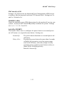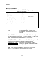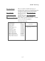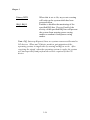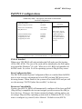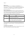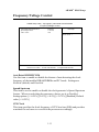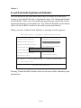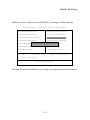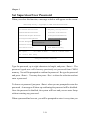
1
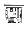
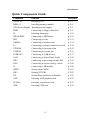
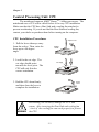
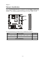
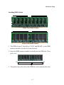
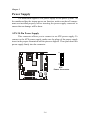
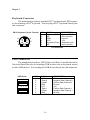
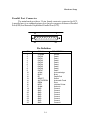
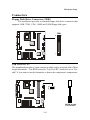
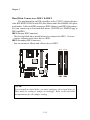
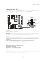
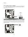
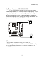
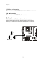
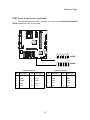
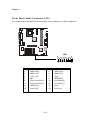
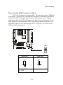
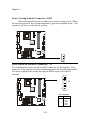
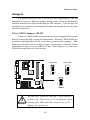
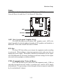
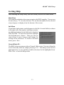
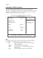
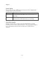
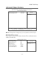
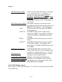
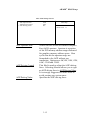
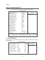
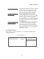
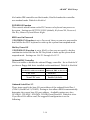
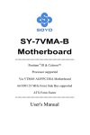
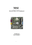
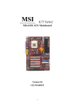
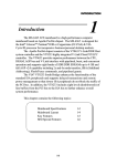
Introduction Introduction The MS6382 MICRO ATX mainboard is a high performance computer mainboard based on KT266/VT8366 and VT8233 chipset. The KT266 chipset is ideal for high quality and high integration desktop and notebook AGP/PCI/LPC computer systems based on Socket A processors. The VT8366 Host system controller provides superior perfromance between CPU, DRAM, AGP bus, and V-Link bus with pipelined, burst, and concurrent operation. The VT8233 V-Link Client controller is a highly integrated PCI/LPC controller. It supports five PCI slots of arbitration and decoding for all integrated functions and LPC bus. For sophisticated power management, the Apollo KT266 chipset provides independent clock stop control for the CPU/SDRAM, PCI, and AGP buses and Dynamic CKE control for powering down of the SDRAM. A seperate suspend-well plane is implemented for the SDRAM control signals for the Suspend-to-DRAM operation. Chapter 1 contains the following topics: Mainboard Specifications Mainboard Layout Quick Components Guide Key Features MSI Special Features 1-1 1-2 1-4 1-5 1-6 1-6 Chapter 1 Mainboard Specifications CPU ! Socket A for AMD® DuronTM/AthlonTM processor. ! Support 600MHz up to 1.5GHz processor Chipset ! VIA® VT8366 chipset. (552 BGA) - FSB @200/266MHz - AGP 4x and high bandwidth Vlink host controller - Advanced memory controller support PC200/266 DDR technology ! VIA® VT8233 chipset. (376 BGA) - High bandwidth Vlink client controller - Integrated faster Ethernet controller - Direct sound ready AC97 digital audio controller - Ultra DMA 33/66/100 master mode EIDE controller - Support both ACPI and legacy APM power management Clock Generator ! 100MHz/133MHz clocks are supported. Main Memory ! Support four memory banks using two 184-pin DDR DIMM ! Support a maximum memory size of 2GB Slots ! One (Accelerated Graphics Port) AGP slot. - AGP specification compliant - Support AGP 2.0 1x/2x/4x ! One CNR (Communication Network Riser) slot. ! Three 32-bit Master PCI Bus slots ! Supports 3.3v/5v PCI bus Interface. On-BoardIDE ! Dual Channel master mode IDE controller on the VIA® VT8233 Chipset provides IDE HDD/CD-ROM with PIO, Bus Master and Ultra DMA 33/66/ 100 operation modes. ! Can connect up to four IDE devices. 1-2 Introduction Audio ! Chip Integrated - Direct Sound AC97 Audio ! CT5880 Hardware Audio (Option) On-Board Peripherals ! On-Board Peripherals include: - 1 floppy port supports 2 FDD with 360K, 720K, 1.2M, 1.44M and 2. 88Mbytes. - 2 serial ports (COMA + COM B) - 1 parallel port supports SPP/EPP/ECP mode - 6 USB ports (2 Rear Connectors/ 2 USB Front Pin Headers - 4 ports) - 1 IrDA connector for SIR/ASKIR/HPSIR. - 1 Audio/Game port BIOS ! The mainboard BIOS provides Plug & Play BIOS which detects the peripheral devices and expansion cards of the board automatically. ! The mainboard provides a Desktop Management Interface (DMI) function which records your mainboard specifications. Dimension ! ATX Form Factor: 24.3cm x 23.4cm Mounting ! 6 mounting holes. 1-3 Chapter 1 Mainboard Layout J1 CPU FAN ATX Power Supply SOCKET 462 Top : mouse Bottom: keyboard USB Top : port 1 Bottom: port 2 J2 .,, J3 Top : LPT Bottom: COM A COM B 86&!$$ 1,- 1,- CD_IN Bottom: Line-Out Line-In Mic MODEM_IN Top : Midi / Game port BATT + JBAT1 ,,4 SW1 PCI Slot ,,4 AUX_IN AGP Slot +6#&& JMDM1 JUSB2 JUSB1 MS-6382 MICRO ATX Mainboard 1-4 JGL1 SFAN1 JAU1 J10 PCI Slot CNR BIOS 86& !! JFP1 PCI Slot JGS1 Introduction Quick Components Guide Component Socket 462 DDR1~2 ATX Power Supply FDD1 J2 IDE1 & IDE2 JFP1 JMDM1 J1 CPUFAN SYSFAN JUSB1 & 2 JAU1 JGL1 JGS1 J3 JBAT1 SW1 J10 AGP PCI Slot CNR Function Installing CPU Installing memory module Installing power supply Connecting to floppy disk drive Inserting thermistor Connecting to HDD drive Connecting to case Connecting to modem card Connecting to chassis intrusion switch Connecting to processor fan Connecting to system fan Connecting to USB devices Connecting to Front Panel Audio Connecting to powering saving LED Connecting to power saving switch Connecting to IR module Setting clear CMOS Setting CPU FSB Setting Beep on Buzzer or Speaker Inserting AGP graphics card Inserting expansion cards Inserting CNR card 1-5 Reference p. 2-2 p. 2-4 p. 2-6 p. 2-11 p. 2-11 p. 2-12 p. 2-13 p. 2-14 p. 2-14 p. 2-15 p. 2-15 p. 2-17 p. 2-18 p. 2-19 P. 2-20 p. 2-20 P. 2-21 P. 2-22 p. 2-22 p. 2-23 p. 2-23 p. 2-23 Chapter 1 Key Features ! ! ! ! ! ! ! ! ! ! Micro ATX Form Factor with PC99 color connector Support Accelerated Graphic Port (AGP) Add-On Card Support AMD® PGA Socket A Duron/Athlon processors at 200/ 266MHz System Bus Frequencies Chip Integrated Audio (CT5880 hardware option) PC Alert System Hardware Monitor Support DMI (Desktop Management Interface) through BIOS LAN Wake Up Function Modem (Internal/External) Ring Wake Up Function Support PCI 2.2 Suspend to RAM/Disk MSI Special Features The MSI special features are designed by MSI R&D which are only available in MSI mainboards. The 6382 mainboard is equipped with PC AlertTM III. 1-6 Introduction PC Alert III The PC AlertTM III is a utility you can find in the CD-ROM. The utility is just like your PC doctor that can detect the following PC hardware status during real time operation: * monitor CPU & system temperature * monitor fan speed * monitor system voltage * monitor chassis intrusion If one of the items above is abnormal, the program main screen will be immediately shown on the screen, with the abnormal item highlighted in red. This will continue to be shown until user disables warning. Features: ! Network Management - Monitoring & remote control ! Basic System Utilities - Scandisk & Defragment to maintain your HDD ! 3D Graphics Design - Enables a more friendly user interface ! Software Utilities - SoftCooler Optimized Cooling - Doctor Y2K diagnoses Y2K problems - BusRacing function adjusts F.S.B under Windows 95/98 - MoSpeed speeds up your modem transmission 1-7 Hardware Setup Hardware Setup This chapter provides you with the information about hardware setup procedures. While doing the installation, be careful in holding the components and follow the installation procedures. For some components, if you install in the wrong orientation, the components will not work properly. Besides, please use a grounded wrist strap before handling computer components. Static electricity may damage the components. . This chapter contains the following topics: Central Processing Unit (CPU) Memory Installation Power Supply Back Panel Connectors Jumpers Slots 2-1 2-2 2-4 2-6 2-7 2-11 2-21 2-24 Chapter 2 Central Processing Unit: CPU The mainboard supports AMD® DuronTM / Athlon processors. The mainboard uses a CPU socket called Socket A for easy CPU installation. Make sure that the CPU has a Heat Sink and a cooling fan attached to prevent overheating. If you do not find the Heat Sink and cooling fan, contact your dealer or purchase them before turning on the computer. CPU Installation Procedures Open Lever 1. Pull the lever sideways away from the socket. Then, raise the lever up to a 90-degree angle. Sliding Plate 2. Look for the cut edge. The cut edge should point towards the lever pivot. The CPU will only fit in the correct orientation. Cut edge 3. Hold the CPU down firmly, and then close the lever to complete the installation. ! WARNING! Close Lever Overheating will seriously damage the CPU and system. After inserting the Heat Sink and cooling fan , check if the cooling fan can work properly to protect the CPU. 2-2 Hardware Setup CPU Core Speed Derivation Procedure The mainboard can not automatically set the CPU Host Bus Frequency Clock. Please refer to 2-22 SW1 for the manual setting. If CPU Clock Core/Bus ratio then CPU core speed ! WARNING! = = = = = 100MHz (set by SW1) 7 Host Clock x Core/Bus ratio 100MHz x 7 700MHz OVERCLOCKING The motherboard are designed to support overclocking. Make sure your components are able to tolerate such abnormal setting while doing overclocking. Any attempt to operate beyond product specifications is not recommended. We do not guarantee the damages or risks caused by inadequate operation or beyond product specification. 2-3 Chapter 2 Memory Installation The mainboard provides 2 sockets for 184-pin single or double side DDR memory modules. To operate properly, at least one DDR module must be installed. The mainboard supports the memory size from 32MB to 2 GB. SOCKET 462 DDR1 DDR2 You can install memory modules in any combination as follows: Socket Memory Module Total Memory Socket 1 (Bank 0 & Bank 1) 32MB, 64MB, 128MB, 256MB, 512MB 32MB~512MB Socket 2 (Bank 2 & Bank 3) 32MB, 64MB, 128MB, 256MB, 512MB 32MB~512MB Total System Memory 2-4 32MB~2GB Hardware Setup Installing DDR Module Single Sided DDR Module Double Sided DDR Module 1. The DDR slot has 2 Notch Keys VOLT and DRAM, so the DDR memory module can only fit in one direction. 2. Insert the DDR memory module vertically into the DDR slot. Then push it in. VOLT 3. The plastic clip at the side of the DDR slot will automatically close. 2-5 Chapter 2 Power Supply The mainboard supports ATX power supply for the power system. As the mainboard has the instant power on function, make sure that all components are installed properly before inserting the power supply connector to ensure that no damage will be done. ATX 20-Pin Power Supply 11 1 20 10 This connector allows you to connect to an ATX power supply. To connect to the ATX power supply, make sure the plugs of the power supply insert in the proper orientation and the pins are aligned. Then push down the power supply firmly into the connector. SOCKET 462 ATX Power Connector 2-6 Hardware Setup Back Panel The Back Panel provides the following connectors: Mouse Keyboard Midi/Joystick Parallel USB COM A COM B L-out L-in MIC Mouse Connector The mainboard provides a standard PS/2® mouse mini DIN connector for attaching a PS/2® mouse. You can plug a PS/2® mouse directly into this connector. PS/2 Mouse (6-pin Female) 6 5 4 3 2 1 PIN 1 2 3 4 5 6 SIGNAL Mouse DATA NC GND VCC Mouse Clock NC DESCRIPTION Mouse DATA No connection Ground +5V Mouse clock No connection Pin Definition 2-7 Chapter 2 Keyboard Connector The mainboard provides a standard PS/2® keyboard mini DIN connector for attaching a PS/2® keyboard. You can plug a PS/2® keyboard directly into this connector. PS/2 Keyboard (6-pin Female) 6 5 4 3 2 1 PIN 1 2 3 4 5 6 SIGNAL Keyboard DATA NC GND VCC Keyboard Clock NC DESCRIPTION Keyboard DATA No connection Ground +5V Keyboard clock No connection Pin Definition USB Connectors The mainboard provides a UHCI (Universal Host Controller Interface) Universal Serial Bus root for attaching USB devices such as keyboard, mouse or other USB devices. You can plug the USB device directly into this connector. USB Ports 1 2 3 4 5 6 7 8 PIN 1 2 3 4 5 6 7 8 SIGNAL VCC -Data 0 +Data0 GND VCC -Data 1 +Data 1 GND DESCRIPTION +5V Negative Data Channel 0 Positive Data Channel 0 Ground +5V Positive Data Channel 1 Negative Data Channel 1 Ground USB Port Description 2-8 Hardware Setup Parallel Port Connector The mainboard provides a 25 pin female centronic connector for LPT. A parallel port is a standard printer port that also supports Enhanced Parallel Port (EPP) and Extended Capabilities Parallel Port (ECP). 13 1 14 25 Pin Definition PIN 1 2 3 4 5 6 7 8 9 10 11 12 13 14 15 16 17 18 19 20 21 22 23 24 25 SIGNAL STROBE DATA0 DATA1 DATA2 DATA3 DATA4 DATA5 DATA6 DATA7 ACK# BUSY PE SELECT AUTO FEED# ERR# INIT# SLIN# GND GND GND GND GND GND GND GND 2-9 DESCRIPTION Strobe Data0 Data1 Data2 Data3 Data4 Data5 Data6 Data7 Acknowledge Busy Paper End Select Automatic Feed Error Initialize Printer Select In Ground Ground Ground Ground Ground Ground Ground Ground1 Chapter 2 Serial Port Connectors: COM A & COM B The mainboard has two 9-pin male DIN connectors for serial port COM A and COM B. You can attach a mouse or other serial devices directly into this connector. 9-Pin Male DIN Connectors Pin Definition PIN 1 2 3 4 5 6 7 8 9 1 2 3 4 5 6 7 8 9 SIGNAL DCD SIN SOUT DTR GND DSR RTS CTS RI DESCRIPTION Data Carry Detect Serial In or Receive Data Serial Out or Transmit Data Data Terminal Ready) Ground Data Set Ready Request To Send Clear To Send Ring Indicate Joystick/Midi Connectors You can connect game joysticks or game pads to this 15-pin female connector for playing game. You can also connect MIDI devices for playing or editing professional audio. Audio Port Connectors Line Out is a connector for headphone or speakers. Line In is used for external CD player, tape players or other audio devices to be recorded by your computer or played through the Line Out. Mic is a connector for the microphone. L-out L-in 2-10 MIC Hardware Setup Connectors Floppy Disk Drive Connector: FDD1 The mainboard provides a standard floppy disk drive connector that supports 360K, 720K, 1.2M, 1.44M and 2.88M floppy disk types. FDD1 SOCKET 462 34 33 2 1 Top Tech III: J2 The mainboard provides a 2-pin connector which can be inserted with a 20cm length thermistor. The BIOS setup for Top Tech III should be set to Enable if you want to use the thermistor to detect the components temperature. SOCKET 462 20CM length Thermistor 2-11 Chapter 2 Hard Disk Connectors: IDE1 & IDE2 The mainboard has an IDE controller on the VT8233 chipset that provides IDE HDD/CD-ROM with PIO, Bus Master and Ultra DMA66/100 operations modes. It has two HDD connectors IDE1 (Primary) and IDE2 (Secondary). You can connect up to four hard disk drives, CD-ROM or 120MB Floppy to IDE1 and IDE2. IDE1 (Primary IDE Connector) - The first hard disk drive should always be connected to IDE1. You can connect a Master and a Slave drive to IDE1. IDE2 (Secondary IDE Connector) - You can connect a Master and a Slave drive to IDE2. 40 39 40 39 2 1 2 1 SOCKET 462 IDE1 IDE2 !TIP: If you install two hard disks, you must configure the second drive to Slave mode by setting its jumper accordingly. Refer to the hard disk documentation for the jumper setting. 2-12 Hardware Setup Case Connector: JFP1 The case connector block JFP1 allows you to connect the Power Switch, Reset Switch, Power LED, Speaker, Key Lock and HDD LED. SOCKET 462 Keylock 14 15 + Power Switch Dual Color LED Single Color LED Buzzer (short pin) + HDD LED Power LED Speaker Reset Switch JFP1 Power Switch Connect to a 2-pin push button switch. Reset Switch Reset switch is used to reboot the system rather than turning the power ON/OFF. Avoid rebooting while the HDD LED is lit. You can connect the Reset switch from the system case to this pin. Power LED The Power LED is lit while the system power is on. You can connect the Power LED from the system case to this pin. There are two types of LED that you can use: 3-pin single color LED or 2-pin dual color LED (ACPI request). a. 3 pin single color LED connector to pin 4,5 & 6. This LED will lit when the system is on. b. 2 pin dual color LED connector to pin 5 & 6. GREEN color: Indicate the system is in full-on mode. ORANGE color: Indicate the system is in suspend mode. Speaker Speaker from the system case is connected to this pin. If on-board Buzzer is available: Short pin 14-15: On-board Buzzer Enabled. Open pin 14-15: On-board Buzzer Disabled. HDD LED HDD LED shows the activity of a hard disk drive. Avoid turning the power off while the HDD led is lit. You can connect the HDD LED from the system case to this pin. 2-13 Chapter 2 Wake On Ring Connector: JMDM1 This connector allows you to connect to a modem card with Wake On Ring function. The connector will power on the system when a signal is received through the modem card. SOCKET 462 5VSB NC GND MDM_WAKEUP NC JMDM1 Chassis Intrusion Switch Connector: J1 This connector is connected to a 2-pin chassis switch. If the chassis is opened, the switch will be short. The system will record this status and show a warning message on the screen. To clear the warning, you must enter the BIOS utility and clear the record. SOCKET 462 J1 2-14 Hardware Setup Fan Power Connectors: CPU FAN/SYSFAN The CPUFAN (processor fan) and SYSFAN (system fan) support system cooling fan with +12V. It supports three pin head connector. When connecting the wire to the connector, always take note that the red wire is the positive and should be connected to the +12V, the black wire is Ground and should be connected to GND. As the mainboard has a System Hardware Monitor chipset on-board, you must use a specially designed fan with speed sensor to take advantage of the CPU fan control. SENSOR +12V GND CPU FAN SOCKET 462 SYSFAN GND +12V SENSOR "Note: 1. Always consult the vendor for proper CPU cooling fan. 2. CPU Fan supports the fan control. You can install the PC Alert utility that will automatically control the CPU Fan speed according to the actual CPU temperature. 2-15 Chapter 2 AUX Line In Connector This connector is used for DVD Add on Card with Line In connector. CD_In Connector This connector is for CD-ROM audio connector. Modem_In This connector is for Modem with internal voice connector. Mono_Out is connected to the Modem Speaker Out connector. Phone_In is connected to the Modem Microphone In connector. SOCKET 462 L GND R CD_IN Phone_In GND Mono_Out Modem_In L GND R AUX_IN 2-16 Hardware Setup USB Front Connectors (optional) The mainboard provides you with two optional Universal Serial Bus (USB) connectors for front panel. SOCKET 462 10 2 10 2 JUSB1 9 1 10 2 10 2 JUSB2 9 1 JUSB2 Pin Definition JUSB1 Pin Definition Pin Description Pin Description Pin Description Pin 1 VCC 2 GND 1 VCC 2 GND 3 USB0- 4 GND 3 USB2- 4 GND 5 USB0+ 6 USB1+ 5 USB2+ 6 USB3+ 7 GND 8 USB1- 7 GND 8 USB3- 9 GND 10 VCC 9 GND 10 VCC 2-17 Description Chapter 2 Front Panel Audio Connector:JAU1 You can connect an optional Front Panel audio connector to this connector. SOCKET 462 JAU1 PIN Description PIN 1 3 5 7 9 11 13 15 GND (ALO) GND (+12) +12V (1A) MIC Front Line Out (R) Front Line Out (L) GND (FLO) Line In (R) 2-18 2 4 6 8 10 12 14 16 2 16 1 15 Description GND (ALO) GND (+12) (Cut) GND (MIC) Line Next (R) Line Next (L) (Cut) Line In (L) Hardware Setup Power Saving LED Connector: JGL1 JGL1 can be connected with an LED. There are two types of LED that you can use: 3-pin LED or 2-pin LED(ACPI request). When the 2-pin LED is connected to JGL1, the light will turn green, when system is On. During sleep mode, the 2-pin LED will change color from Green to Orange. For 3-pin LED, when LED is connected to JGL1, this will light when the system is On and blinks when it is in suspend/sleep mode. See page 3-19 (Power status LED) for further instruction. SOCKET 462 JGL1 1 3 3-pin LED 2-pin LED Orange Color Green Color Green Color ! ! Orange Color 1-2 Single Color 1-3 Blink 1-2 Dual Color 2-19 Chapter 2 Power Saving Switch Connector: JGS1 This connector allows you to connect to a power saving switch. When the switch is pressed, the system immediately goes into suspend mode. You can press any key to wake up the system. SOCKET 462 JGS1 IrDA Infrared Module Connector: J3 The mainboard provides one infrared (IR) connector for IR modules. This connector is for optional wireless transmitting and receiving infrared module. You must configure the setting through the BIOS setup to use the IR function. 1 SOCKET 462 J3 3 Pin Definition 2-20 PIN SIGNAL 1 2 3 4 5 VCC NC IRRX GND IRTX Hardware Setup Jumpers The motherboard provides you with the following jumpers to set the computers function. Besides jumper setting, some of the motherboards onboard functions are adjusted through the DIP switches. This section will mention how to change your motherboards function through the use of jumpers and/or switches. Clear CMOS Jumper: JBAT1 There is a CMOS RAM on board that has a power supply from external battery to keep the data of system configuration. With the CMOS RAM, the system can automatically boot OS every time you turn on the computer . That battery has long life time for at least 5 years. If you want to clear the system configuration, you can use the JBAT1 (Clear CMOS Jumper ) to clear data. Follow the steps below to clear the data: SOCKET 462 keep data clear data 1 1 3 3 1 3 JBAT1 ! WARNING! You can clear CMOS by shorting 2-3 pin while the system is off. Then return to 1-2 pin position. Avoid clearing the CMOS while the system is on; it will damage the mainboard. 2-21 Chapter 2 CPU FSB Jumper: SW1 This jumper allows you to set CPU FSB frequency. 1 1 3 3 100MHz SOCKET 462 133MHz 1 3 SW1 Beep On Buzzer/Speaker Jumper: J10 This jumper is used to set the beep on Buzzer or Speaker function. SOCKET 462 1 1 3 3 To Buzzer To Speaker 1 3 J10 2-22 Hardware Setup Slots The motherboard provides one AGP slot, one CNR (Communication Network Riser) slot and three 32-bit Master PCI Bus Slots. AGP PCI Slot CNR AGP Slot (Accelerated Graphics Port) The AGP Slot allows you to insert AGP graphics cards. AGP is designed specially for the throughput demands of 3-D graphics and introduce a dedicated 32 bits wide channel and runs at 66MHz. PCI Slot The three PCI slots allow you to insert the expansion cards according to your needs. When adding or removing expansion cards, make sure that you unplug the power supply. Meanwhile, read the documentation for the expansion card and make any necessary hardware or software settings for the expansion card, such as jumpers, switches or BIOS. CNR (Communication Network Riser) The CNR slot allows you to insert the CNR expansion cards. CNR is a specially designed network, audio, or modem riser card for ATX family motherboards. The processing is done through software setup and controlled by the motherboards chipset. 2-23 Chapter 2 PCI Interrupt Request The IRQ, abbreviation of interrupt request line, and pronounced I-R-Q, are hardware lines over which devices can send interrupt signals to the microprocessor. The PCI IRQ pins are typically connected to the PCI bus INTA#-INTD# pins as follows. Order1 Order2 Order3 Order4 AGP INTA INTB INTC INTD PCI1 INTA INTB INTC INTD PCI2 INTB INTC INTD INTA PCI3 INTC INTD INTA INTB Audio INTD INTA INTB INTC USB1 INTD INTA INTB INTC USB2 INTD INTA INTB INTC USB3 INTD INTA INTB INTC AGP & PCI1 shared. Audio & USB1,2,3 shared. 2-24 AWARD® BIOS Setup ! AWARD® BIOS Setup The mainboard uses AWARD® BIOS ROM that provides a Setup utility for users to modify the basic system configuration. The information is stored in a battery-backed CMOS RAM so it retains the Setup information when the power is turned off. This chapter provides you with the overview of the BIOS Setup program. It contains the following topics: Entering Setup Control Keys Getting Help The Main Menu Standard CMOS Feature Advanced BIOS Features Advanced Chipset Features Integrated Peripherals Power Management Setup PnP/PCI Configurations PC Health Status Frequency/Voltage Control Load Fail-Safe/Optimized Defaults Set Supervisor/User Password Save & Exit Setup Exit Without Saving 3-1 3-2 3-2 3-3 3-4 3-6 3-9 3-13 3-16 3-23 3-29 3-31 3-33 3-34 3-36 3-38 3-39 Chapter 3 Entering Setup Power on the computer and the system will start POST (Power On Self Test) process. When the message below appears on the screen, press <DEL> key to enter Setup. Hit DEL if you want to run SETUP If the message disappears before you respond and you still wish to enter Setup, restart the system by turning it OFF and On or pressing the RESET button. You may also restart the system by simultaneously pressing <Ctrl>, <Alt>, and <Delete> keys. Control Keys <↑> Move to the previous item <↓> Move to the next item <←> Move to the item in the left hand <→> Move to the item in the right hand <Enter> Select the item <Esc> Jumps to the Exit menu or returns to the main menu from a submenu <+/PU> Increase the numeric value or make changes <-/PD> Decrease the numeric value or make changes <F1> General help, only for Status Page Setup Menu and Option Page Setup Menu <F5> Restore the previous CMOS value from CMOS, only for Option Page Setup Menu <F6> Load the default CMOS value from Fail-Safe default table, only for Option Page Setup Menu <F7> Load Optimized defaults <F10> Save all the CMOS changes and exit 3-2 AWARD® BIOS Setup Getting Help After entering the Setup utility, the first screen you see is the Main Menu. Main Menu The main menu displays the setup categories the BIOS supplies. You can use the arrow keys ( ↑↓ ) to select the item. The on-line description for the selected setup category is displayed on the bottom of the screen. Sub-Menu If you find a right pointer symbol appears to the left of certain fields (as shown in the right view), that means a sub-menu containing additional options for the field can be launched IDE Primary Master from this field. To enter the sub-menu, highlight ! IDE Primary Slave the field and perss <Enter>. Then you can use ! IDE Secondary Master control keys to move between and change the ! IDE Secondary Slave settings of the sub-menu. To return to the main ! menu, press <Esc>. General Help <F1> The BIOS setup program provides a General Help screen. You can call up this screen from any menu by simply pressing <F1>. The Help screen lists the appropriate keys to use and the possible selections for the highlighted item. Press <Esc> to exit the Help screen. 3-3 Chapter 3 The Main Menu Once you enter AWARD® BIOS CMOS Setup Utility, the Main Menu will appear on the screen. The Main Menu displays eleven configurable functions and two exit choices. Use arrow keys to move among the items and press <Enter> to enter the sub-menu. CMOS Setup Utility - Copyright(C) 1984-2001 Award Software !Standard CMOS Features !Frequency/Voltage Control !Advanced BIOS Features Load Fail-Safe Defaults !Advanced Chipset Features Load Optimized Defaults !Integrated Peripherals Set Supervisor Password !Power Management Setup Set User Password !PnP/PCI Configurations Save & Exit Setup !PC Health Status Exit Without Saving ESC : Quit F9 : Menu in BIOS ↑ ↓ ← → : Select Item F10 : Save & Exit Setup Time, Date, Hard Disk Type… Standard CMOS Features Use this menu for basic system configurations, such as time, date etc. Advanced BIOS Features Use this menu to setup the items of Award® special enhanced features. Advanced Chipset Features Use this menu to change the values in the chipset registers and optimize your systems performance. Integrated Peripherals Use this menu to specify your settings for integrated peripherals. 3-4 AWARD® BIOS Setup Power Management Setup Use this menu to specify your settings for power management. PnP/PCI Configurations This entry appears if your system supports PnP/PCI. PC Health Status This entry displays the current status of your PC. Frequency/Voltage Control Use this menu to specify your settings for frequency/voltage control. Load Fail-Safe Defaults Use this menu to load the BIOS default values for the minimal/stable performance of your PC. Load Optimized Defaults Use this menu to load the default factory settings for BIOS for optimal system performance. Supervisor Password Use this menu to set Supervisor Password. User Password Use this menu to set User Password. Save & Exit Setup Save changes to CMOS and exit setup. Exit Without Saving Abandon all changes and exit setup. 3-5 Chapter 3 Standard CMOS Features The items inside Standard CMOS Features menu are divided into 13 categories. Each category includes none, one or more setup items. Use the arrow keys to highlight the item you want to modify and use the <PgUp> or <PgDn> keys to switch to the value you prefer. CMOS Setup Utility - Copyright(C) 1984-2001 Award Software Standard CMOS Features Date (mm:dd:yy) : Time (hh:mm:ss) : Fri, Mar 2 2001 00:00:00 !IDE Primary Master !IDE Primary Slave !IDE Secondary Master !IDE Secondary Slave Menu Level ! Change the day, month, year and century Drive A Drive B 1.44 M, 3.5 in. None Video Halt On EGA/VGA All, But Keyboard Base Memory Extended Memory Total Memory Item Help 640K 65472K 1024K ↑ ↓ → ←:Move Enter:Select +/-/PU/PD:Value F10:Save ESC:Exit F1:General Help F5:Previous Values F6:Fail-Safe Defaults F7:Optimized Defaults Date This allows you to set the system to the date that you want (usually the current date). The format is <day><month> <date> <year>. day Day of the week, from Sun to Sat, determined by BIOS. Read-only. month The month from Jan. through Dec. date The date from 1 to 31 can be keyed by numeric function keys. year The year depends on the year of the BIOS. 3-6 AWARD® BIOS Setup Time This allows you to set the system time that you want (usually the current time). The time format is <hour> <minute> <second>. IDE Primary Master/Primary Slave/Secondary Master/Secondary Slave Press PgUp/<+> or PgDn/<-> to select the hard disk drive type. The specification of hard disk drive will show up on the right hand according to your selection. IDE Primary Master IDE HDD Auto-Detection Press Enter IDE Primary Master Access Mode Auto Auto Capacity 15021MB Cylinder Head Precomp Landing Zone Sector 291024 16 Access Mode Capacity Cylinder Head Precomp Landing Zone Sector 29103 63 Item Help Menu Level !! To auto-detect the HDDs size, head...on this channel 0 The settings are Auto, CHS, LBA and Large. The formatted size of the storage device. Number of cylinders. Number of heads. Write precompensation. Cylinder location of the landing zone. Number of sectors. Drive A/B This item allows you to set the type of floppy dirves installed. Available options are None, 360K, 5.25 in., 1.2M, 5.25 in., 720K, 3.5 in., 1.44M, 3.5 in., 2.88M, 3.5 in.. The default value for Floppy Drive A is 1.44M, 3.5 in, and for Floppy Drive B is None. 3-7 Chapter 3 system . Available options are EGA/VGA , CGA 40, CGA 80 and Mono. Default value is EGA/VGA. Halt On The item determines whether the system will stop if an error is detected at boot. Available options are: All Errors No Errors All, But Keyboard All, But Diskette All, But Disk/Key The system stops when any error is detected. The system doesnt stop for any detected error. The system doesnt stop for a keyboard error. The system doesnt stop for a disk error. The system doesnt stop for either a disk or a keyboard error. 3-8 AWARD® BIOS Setup Advanced BIOS Features CMOS Setup Utility - Copyright(C) 1984-2001 Award Software Advanced BIOS Features Anti-virus Protection CPU Internal Cache External Cache CPU L2 Cache ECC Checking Quick Power On Self Test First Boot Device Second Boot Device Third Boot Device Boot Other Device Swap Floppy Drive Boot Up Floppy Seek Boot Up Numlock Status Gate A20 Option Typematic Rate Setting xTypematic Rate (Chars/Sec) xTypematic Delay (Msec) Security Option OS Select for DRAM > 64MB Video BIOS Cacheable Disabled Enabled Enabled Enabled Enabled Floppy HDD-0 LS120 Enabled Disabled Enabled On Fast Disabled 6 250 Setup Non-OS2 Disabled Item Help Menu Level ! Allows you to choose the VIRUS warning feature for IDE Hard Disk boot sector protection. If this function is enabled and someone attempt to write data into this area, BIOS will show a warning message on screen and alarm beep. ↑ ↓ → ←:Move Enter:Select +/-/PU/PD:Value F10:Save ESC:Exit F1:General Help F5:Previous Values F6:Fail-Safe Defaults F7:Optimized Defaults Anti-Virus Protection The item is to set the Virus Warning feature for IDE Hard Disk boot sector protection. If the function is enabled and any attempt to write data into this area is made, BIOS will display a warning message on screen and beep. Settings are Disabled and Enabled. Default value is Disabled. CPU Internal Cache The item allows you to turn on or off CPUs internal (L1) cache. Settings are Enabled (default) and Disabled. External Cache This allows you to turn on or off L2 (Level 2) cache memory for CPU. Settings are Enabled (default) and Disabled. 3-9 Chapter 3 CPU L2 Cache ECC Checking This allows you to enable or disable the ECC (Error-Correcting Code) feature to check the data when it passes through L2 cache memory. Settings are Enabled and Disabled. Default value is Enabled. Quick Power On Self Test Setting the item to Enabled allows the system to shorten boot time since it will skip some check items. Settings are Enabled and Disabled. Default value is Enabled. First/Second/Third Boot Device The items allow you to set the sequence of boot devices where BIOS attempts to load the disk operating system. The settings are: HDD-0 The system will boot from the first HDD. HDD-1 The system will boot from the second HDD. HDD-2 The system will boot from the third HDD. HDD-3 The system will boot from the fourth HDD. Floppy The system will boot from floppy drive. ZIP100 The system will boot from ATAPI ZIP drive. LS-120 The systm will boot from LS-120 drive. SCSI The system will boot from the SCSI. LAN The system will boot from the Network drive. CD-ROM The system will boot from the CD-ROM. Disabled Disable this sequence. Boot Other Device Setting the option to Enabled allows the system to try to boot from other device if the system fails to boot from the 1st/2nd/3rd boot device. Swap Floppy Drive Setting to Enabled will swap floppy drives A: and B:. Default is Disabled. Boot Up Floppy Seek Setting to Enabled will make BIOS seek floppy drive A: before booting the system. Setting options are Disabled and Enabled. Default is Enabled. 3-10 AWARD® BIOS Setup Boot Up NumLock Status This item is to set the Num Lock status when the system is powered on. Setting to On will turn on the Num Lock key when the system is powered on. Setting to Off will allow end users to use the arrow keys on the numeric keypad. Settings are On and Off. Default is On. Gate A20 Option This item is to set the Gate A20 status. A20 refers to the first 64KB of extended memory. When the default value Fast is selected, the Gate A20 is controlled by Port92 or chipset specific method resulting in faster system performance. When Normal is selected, A20 is controlled by a keyboard controller or chipset hardware. Typematic Rate Setting This item is used to enable or disable the typematic rate setting including Typematic Rate & Typematic Delay. Typematic Rate (Chars/Sec) After Typematic Rate Setting is enabled, this item allows you to set the rate (characters/second) at which the keys are accelerated. Setting options are 6, 8, 10, 12, 15, 20, 24 and 30. Typematic Delay (Msec) This item allows you to select the delay between when the key was first pressed and when the acceleration begins. Setting options are 250, 500, 750 and 1000. OS Select for DRAM > 64MB This allows you to run the OS/2® operating system with DRAM larger than 64MB. When you choose the default value Non-OS2, you cannot run the OS/2® operating system with DRAM larger than 64MB. But it is possible if you choose OS2. Default value is Non-OS2. 3-11 Chapter 3 Security Option This specifies the type of BIOS password protection that is implemented. Setting options are described below: Option Description Setup (default) The password prompt appears only when end users try to run Setup. System A password prompt appears every time when the compuer is powered on or when end users try to run Setup. Video BIOS Cacheable Setting to Enabled allows caching of the Video BIOS ROM at C0000hF7FFFh and leads to better video performance. But any program attempt to write to this memory area will cause a system error. Default value is Disabled. 3-12 AWARD® BIOS Setup Advanced Chipset Features CMOS Setup Utility - Copyright(C) 1984-2001 Award Software Advanced Chipset Features !DRAM Clock/Drive Control !AGP & P2P Bridge Control Press Enter Press Enter Item Help Menu Level ! ↑ ↓ → ←:Move Enter:Select +/-/PU/PD:Value F10:Save ESC:Exit F1:General Help F5:Previous Values F6:Fail-Safe Defaults F7:Optimized Defaults !Note: Change these settings only if you are familiar with the chipset. DRAM Clock/Drive Control Press <Enter> to enter the sub-menu, and you will see a sub-menu screen similar to the following: DRAM Clock/Drive Control DRAM Timing by SPD xDRAM Frequency (MHz) xSDRAM CAS Latency xBank Interleave DDR 1T Command Current Host (FSB) Clock Current DRAM Frequency Current DDR Frequency Yes Auto Auto Auto Disabled 100MHz 133MHz 266MHz 3-13 Item Help Menu Level !! Chapter 3 DRAM Timing by SPD Selects whether DRAM timing is controlled by the SPD EPROM on the DRAM card. Setting to No not only makes DRAM Frequency, SDRAM CAS Latency and Bank Interleave adjustable but also sets SDRAM Precharge/RAS to CAS/RAS Pulse to 3T/3T/6T. DRAM Frequency (MHz) The chipset supports synchronous and asynchronous mode between host clock and DRAM clock frequency. The settings are: Auto: BIOS automatically determines the DRAM clock frequency. HCLK+33: The DRAM clock will be equal to Host Clock plus 33MHz. For example, if the Host Clock is 100MHz, the DRAM clock will be 133MHz. HCLK: The DRAM clock will be equal to the Host Clock. HCLK-33: The DRAM clock will be equal to the Host Clock minus 33MHz. For example, if the Host Clock is 133MHz, the DRAM clock will be 100MHz. SDRAM CAS Latency Controls the time delay (in clock cycles) before SDRAM starts a read command after receiving it. Settings are Auto, 2, 2.5 and 3. Bank Interleave Enables or disables bank interleave feature. Settings are Auto and Disabled. Current Host (FSB) Clock: Displays current host clock frequency. Current DRAM Frequency:Displays current DRAM clock frequency. Current DDR Frequency: This display-only filed appears only when DDR DRAMs are installed. AGP & P2P Bridge Control Press <Enter> to enter the sub-menu. You will see a sub-menu screen similar to the following: 3-14 AWARD® BIOS Setup AGP & P2P Bridge Control AGP Aperture Size AGP Driving Control x AGP Driving Value AGP Aperture Size AGP Driving Control AGP Driving Value 64M Auto DA Item Help Menu Level !! Selects the size of the Accelerated Graphics Port (AGP) aperture. Aperture is a portion of the PCI memory address range dedicated for graphics memory address space. Host cycles that hit the aperture range are forwarded to the AGP without any translation. Options are 4M, 8M, 16M, 32M, 64M, 128M and 256M. This filed is used to adjust the AGP driving force. Selecting Manual allows you to type an AGP driving force in AGP Driving Value. It is strongly suggested to select Auto to avoid causing any system error. Specifies the AGP driving force. 3-15 Chapter 3 Integrated Peripherals CMOS Setup Utility - Copyright(C) 1984-2000 Award Software Integrated Peripherals OnChip IDE Device !VIA OnChip PCI Device !VIA Init Display First Press Enter Press Enter PCI Slot All Enabled Disabled Enabled BUTTON ONLY Enter Ctrl-F1 Enabled 3F8/IRQ4 2F8/IRQ3 Normal Hi, Lo Enabled Half IR-Rx2Tx2 378/IRQ7 ECP EPP1.7 3 Off 201 (option) 330 (option) 10 (option) OnChip USB Controller USB Keyboard Support IDE HDD Block Mode POWER ON Function x KB Power ON Password x Hot Key Power ON Onboard FDC Controller Onboard Serial Port 1 Onboard Serial Port 2 UART Mode Select xRxD, TxD Active xIR Transmission Delay xUR2 Duplex Mode xUse IR Pins Onboard Parallel Port Parallel Port Mode xEPP Mode Select ECP Mode Use DMA PWRON After PWR-Fail Game Port Address Midi Port Address Midi Port IRQ Item Help Menu Level ! ↑ ↓ → ←:Move Enter:Select +/-/PU/PD:Value F10:Save ESC:Exit F1:General Help F5:Previous Values F6:Fail-Safe Defaults F7:Optimized Defaults VIA OnChip IDE Device Press <Enter> to enter the sub-menu, and a sub-menu similar to the following will appear. OnChip IDE Device OnChip IDE Channel0 OnChip IDE Channel1 Primary Master PIO Primary Slave PIO Secondary Master PIO Secondary Slave PIO Primary Master UDMA Primary Slave UDMA Secondary Master UDMA Secondary Slave UDMA Enabled Enabled Auto Auto Auto Auto Auto Auto Auto Auto 3-16 Item Help Menu Level ! AWARD® BIOS Setup OnChip IDE Channel0/1 Primary/Secondary Master/Slave PIO Primary/Secondary Master/Slave UDMA The integrated peripheral controller contains an IDE interface with support for two IDE channels. Choose the default value Enabled to activate each channel separately. The four fields allow you to set a PIO (Programmed Input/Output) mode for each of the four IDE devices that the onboard IDE interface supports. Modes 0~4 provide increased performance. In Auto mode, BIOS automatically determines the best mode for each IDE device. Ultra DMA implementation is possible only if your IDE device supports it and your operating environment contains a DMA driver. If both your hard drive and software support Ultra DMA, select Auto (default) to enable BIOS support. VIA OnChip PCI Device Press <Enter> to enter the sub-menu. A sub-menu screen similar to the following will appear. OnChip PCI Device VIA-3058 AC97 Audio VIA-3068 MC97 Modem VIA-3043 OnChip LAN Auto (option) Auto Disabled Item Help Menu Level 3-17 !! Chapter 3 VIA-3058 AC97 Audio VIA-3068 MC97 Modem VIA-3043 OnChip LAN Auto allows the mainboard to detect whether an audio device is used. If the device is detected, the onboard VIA AC97 (Audio Codec97) controller will be enabled; if not, the controller is disabled. Disable the controller if you want to use other controller cards to connect an audio device. Settings are Auto (default) and Disabled. Auto allows the mainboard to detect whether a modem is used. If a modem is detected, the onboard VIA MC97 (Modem Codec97) controller will be enabled; if not, the controller is disabled. Disable the controller if you want to use other controller cards to connect modems. Settings are Auto (default) and Disabled. Enables or disables VIA chip integrated LAN controller. Settings are Enalbed and Disabled (default). Init Display First This item specifies which VGA card is your primary graphics adapter. Available options are PCI Slot and AGP. Default value is PCI Slot. OnChip USB Controller The item specifies which USB (Universal Serial Bus) Port is enabled. The settings are All Enabled, 1&2 USB Port, 2&3 USB Port, 1&3 USB Port, 1 USB Port, 2 USB Port, 3 USB Port or All Disabled. Default is All Enabled. USB Keyboard Support Set to Enabled if your system installs and uses an USB keyboard. Default is Disabled. IDE HDD Block Mode This allows your hard disk controller to use the fast block mode to transfer data to and from the hard disk drive. Block mode is also called block transfer, multiple commands or multiple sector read/write. Setting to Ena3-18 AWARD® BIOS Setup bled makes IDE controller use block mode; Disabled makes the controller use standard mode. Default is Enabled. POWER ON Function This controls which button on the PS/2 mouse or keyboard can power on the sytem. Settings are BUTTON ONLY (default), Keyboard 98, Password, Hot Key, Mouse Left and Mouse Right. KB Power On Password If POWER ON Function is set to Password, then you can set a password in this field for the PS/2 keyboard to wake up the system from suspend mode. Hot Key Power ON If POWER ON Function is set to Hot Key, then you can specify a hot key combination in the field for the PS/2 keyboard to wake up the system from suspend mode. Settings are Ctrl-F1 through Ctrl-F12. Onboard FDC Controller This is to enable or disable the onboard Floppy controller. Set to Enabled if you have a floppy disk drive installed on the mainboard. Default is Enabled. If the ISA add-on card has Onboard FDC to be set at FDC exist Disabled None FDC exist Enabled (default) Onboard Serial Port 1/2 These items specify the base I/O port address of the onboard Serial Port 1 (COM 1)/Serial Port 2 (COM 2). Setting to Auto allows BIOS to automatically determine the correct base I/O port address. Available options are Auto, 3F8/IRQ4, 2F8/IRQ3, 3E8/IRQ4, 2E8/IRQ3 and Disabled. Default is Auto. If you have ISA add-on card, the suggested configuration is as the following: 3-19 Chapter 3 If the ISA add-on card has COM4 COM3 COM2 COM1 (I/O:3F8H) (I/O:3F8H) (I/O:3E8H) (I/O:2E8H) ! ! X ! X ! ! ! X X ! X X X ! ! X X ! ! ! X ! X X ! X X ! X ! X ! ! X ! ! X X X ! X ! X ! ! X X ! ! ! X X X X ! Onboard Serial port to be set at PORT1 DISABLED COM3 COM1 COM2 COM1 COM4 COM3 COM2 COM1 COM1 COM2 COM1 COM1 COM1 IRQ ASSIGNED X 4 4 3 4 3 4 3 4 4 3 4 4 4 PORT2 DISABLED COM4 COM2 COM3 COM4 DISABLED DISABLED DISABLED DISABLED COM2 COM3 COM3 COM2 COM2 IRQ ASSIGNED X 3 3 4 3 X X X X 3 4 4 3 3 UART Mode Select The item allows you to determine which Infra Red (IR) function of the onboard I/O chip. Settings are Normal(default), IrDA and ASKIR. RxD, TxD Active The item determines the active of RxD, TxD. Settings are Hi, Lo (default), Hi, Hi, Lo, Hi, Lo, Lo. IR Transmission Delay This enables or disables IR transmission delay feature. Settings are Enabled and Disabled. Default is Enabled. UR2 Duplex Mode This specifies a duplex value for the IR device connected to the IR connector. Full-Duplex mode permits simultaneous two-direction transmission. Half-Duplex mode permits transmission in one direction only at a time. Settings are Half and Full. Default is Half . 3-20 AWARD® BIOS Setup Use IR Pins Consult your IR peripheral documentation to select the correcting of the TxD and RxD signals. Settings are IR-Rx2Tx2 and RxD2, TxD2. Onboard Parallel Port This specifies the base I/O port address of the onboard Parallel Port. Settings are 378/IRQ7, 278/IRQ5, 3BC/IRQ7 and Disabled. Default is 378/ IRQ7. If you have an ISA add-on card, the suggested configuration is as below: If the ISA add-on card has Onboard parallel port to be set as LPT1 LPT2 LPT3 I/O:378H I/O:278H I/O:3BCH ! ! ! ! ! X ! X ! X ! ! ! X X X ! X X X ! X X X PORT ASSIGNED Disabled LPT3 LPT2 LPT1 LPT2 LPT1 LPT1 LPT1 IRQ ASSIGNED X 5 5 7 5 7 7 7 Note: If the onboard parallel port interrupt and ISA add-on card interrupt are in conflict, the parallel port will not work properly. Please disable one of the devices. Parallel Port Mode This item selects the operating mode for the parallel port to support: SPP, EPP, ECP or ECP+EPP. Default is SPP. EPP Mode Select The item selects the EPP version used by the parallel port if the port is set to EPP or ECP+EPP mode. Settings are EPP1.7 and EPP1.9. ECP Mode Use DMA This item automatically specifies an DMA channel 1 or 3 for the Parallel Port when it is set to ECP or ECP+EPPmode. 3-21 Chapter 3 PWRON After PWR-Fail This item specifies whether your system will reboot after a power failure or interrupts occurs. Available settings are: Off (default) Leaves the computer in the power off state. On Reboots the computer. Former-Sts Restores the system to the status before power failure or interrupt occurs. Game/Midi Port Address (option) The items disable or set an address for the onboard Game/MIDI port. Settings for Game port are Disabled, 201 and 209. Settings for Midi port are Disabled, 330, 300 and 290. Midi Port IRQ (option) This specifies an IRQ line for the Midi Port. Settings are 5 and 10. 3-22 AWARD® BIOS Setup Power Management Setup CMOS Setup Utility - Copyright(C) 1984-2000 Award Software Power Management Setup IPCA function Sleep State Power Management Option HDD Power Down Doze Mode Suspend Mode PM Control by APM MODEM Use IRQ Soft-Off by PWRBTN !IRQ/Event Activity Detect Sleep State LED Enabled S1/POS User Define Disable Disable Disable Yes 3 Instant-off Press Enter Single Item Help Menu Level ! ↑ ↓ → ←:Move Enter:Select +/-/PU/PD:Value F10:Save ESC:Exit F1:General Help F5:Previous Values F6:Fail-Safe Defaults F7:Optimized Defaults IPCA Function This item is to activate the ACPI (Advanced Configuration and Power Management Interface) Function. Settings are Enabled and Disabled. Default is Enabled. Sleep State This item specifies the power saving modes for ACPI function. Options are: S1/POS S3/STR The S1 sleep mode is a low power state. In this state, no system context is lost (CPU or chipset) and hardware maintains all system context. The S3 sleep mode is a lower power state where the information of system cofiguration and open applications/files is saved to main memory that remains powered while most other hardware components turn off to save energy. The information stored in memory 3-23 Chapter 3 will be used to restore the system when an wake up event occurs. Default value is S1/POS. Power Management Option This item is used to select the degree (or type) or power saving and is related to these modes: Doze Mode, Suspend Mode and HDD Power Down. There are three options for power management: Min Saving Minimum Power Management. Doze Mode = 1 hour, Suspend Mode = 1 hour Max Saving Maximum Power Management. Doze Mode = 1 min., Suspend Mode = 1 min. User Define Allows end users to configure each mode separately. Each of the ranges are from 1 min. to 1 hour. and disabled except for HDD Power Down which ranges from 1 min. to 15 min. and disabled. Default value is User Define. HDD Power Down If system activity is not detected for the length of time specified in this field, the hard disk drive will be powered down while all other devices remain active. Settings are Disabled and 1 Min through 15 Min. Default is Disabled. Doze Mode If system activity is not detected for the length of time specified in this field, the CPU clock will run at slower speed while all other devices still operate at full speed. Settings are Disabled, 1 Min, 2 Min, 4 Min, 6 Min, 8 Min, 10 Min, 20 Min, 30 Min, 40 Min and 1 Hour. Default is Disabled. Suspend Mode If system activity is not detected for the length of time specified in this field, all devices except CPU will be shut off. Settings are Disabled, 1 Min, 2 Min, 4 Min, 6 Min, 8 Min, 10 Min, 20 Min, 30 Min, 40 Min and 1 Hour. Default is Disabled. 3-24 AWARD® BIOS Setup PM Control by APM Setting to Yes will activate an Advanced Power Management (APM) device to enhance Max Saving mode and stop CPU internal clock. Settings are Yes and No. Default is Yes. MODEM Use IRQ Name the interrupt request (IRQ) line assigned to the modem (if any) on your system. Activity of the selected IRQ always awakens the system. Settings are 3, 4, 5, 7, 9, 10, 11 and NA. Soft-Off by PWRBTN This feature allows users to configure the power button as a normal poweron/-off button or a suspend/resume button. Settings are: Instant-Off Delay 4 Sec. The power button functions as a normal power-on/off button. Pressing the power button for more than 4 seconds will place the system in a very low-power-usage state (Soft-Off state), with only enough circuitry receiving power to detect power button activity or Wake Up On LAN/Ring activity. Default is Instant-Off. 3-25 Chapter 3 IRQ/Event Activity Detect Press <Enter> to enter the sub-menu and the following screen appears: IRQ/Event Activity Detect USB Resume from S3/S4/S5 VGA LPT & COM HDD & FDD PCI Master PowerOn by PCI Card Wake Up On LAN/Ring RTC Alarm Resume x Date (of Month) x Resume Time (hh:mm:ss) IRQs Activity Monitoring ! USB Resume from S3/ S4/S5 Disabled OFF LPT/COM ON OFF Disabled Disabled Disabled 0 0 0 10 Press Enter Item Help Menu Level !! Allows the activity of USB device to wake up the system from S3, S4 or S5 power saving modes. Settings are Enabled and Disabled. Note: S3/S4/S5 are three system states for ACPI, which reduce different amount of power consumption. S3 is STR (Suspend to RAM) sleep mode, S4 is Suspend to Disk mode and S5 is Soft-Off state. VGA, LPT & COM, HDD & FDD, PCI Master, PowerOn by PCI Card, Wake Up On LAN/Ring These items specify whether the system will be awakened from power saving modes when activity or input signal of the specified hardware peripheral or component is detected. Note: To use the function of Wake Up On LAN/Ring, you need to install a LAN card/modem supporting power on function. 3-26 AWARD® BIOS Setup RTC Alarm Resume This is to enable or disable the feature of booting up the system on a scheduled time/date. Settings are Enabled and Disabled(default). Date (of Month) Specifies the date for RTC Alarm Resume. Settings are 0~31. Resume Time (hh:mm: Specifies the time for RTC Alarm Resume. ss) Format is <hour><minute><second>. IRQs Activity Monitoring Press <Enter> to enter the sub-menu. A similar screen to the following appears: IRQs Activity Monitoring Primary INTR IRQ3 (COM2) IRQ4 (COM1) IRQ5 (LPT2) IRQ6 (Floppy Disk) IRQ7 (LPT1) IRQ8 (RTC Alarm) IRQ9 (Reserved) IRQ10 (Reserved) IRQ11 (Reserved) IRQ12 (PS/2 Mouse) IRQ13 (Coprocessor) IRQ14 (IDE Channel 0) IRQ15 (IDE Channel 1) On Enabled Enabled Enabled Enabled Enabled Disabled Disabled Disabled Disabled Enabled Enabled Enabled Disabled 3-27 Item Help Menu Level !!! Chapter 3 Primary INTR IRQ3~IRQ15 When this is set to On, any event occuring will wake up the system which has been powered down. Enables or disables the monitoring of the specified IRQ line. If set to Enabled, the activity of the specified IRQ line will prevent the system from entering power saving modes or awaken it from power saving modes. Note: IRQ (Interrup Request) lines are system resources allocated to I/O devices. When an I/O device needs to gain attention of the operating system, it singals this by causing an IRQ to occur. After receiving the signal, when the operating system is ready, the system will interrupt itself and perform the service required by the I/O device. 3-28 AWARD® BIOS Setup PnP/PCI Configurations CMOS Setup Utility - Copyright(C) 1984-2000 Award Software PnP/PCI Configurations PNP OS Installed Reset Configuration Data Resources Controlled By x IRQ Resources PCI/VGA Palette Snoop Assign IRQ For VGA Assign IRQ For USB Assign IRQ For ACPI No Disabled Auto (ESCD) Press Enter Disabled Enabled Enabled Auto Item Help Menu Level ! Select Yes if you are using a Plug and Play capable operation system Select No if you need the BIOS to configure non-boot devices ↑ ↓ → ←:Move Enter:Select +/-/PU/PD:Value F10:Save ESC:Exit F1:General Help F5:Previous Values F6:Fail-Safe Defaults F7:Optimized Defaults PNP OS Installed When set to YES, BIOS will only initialize the PnP cards used for booting (VGA, IDE, SCSI). The rest of the cards will be initialized by the PnP operating system like Windows® 95 or 98. When set to NO, BIOS will initialize all the PnP cards. So, select Yes if the operating system is Plug & Play aware. Reset Configuration Data The ESCD (Extended System Configuration Data) is a method that the BIOS uses to store resource information for both PNP and non PNP devices in a bit string format. When Enabled, the system will re-built ESCD and you will see the message ESCD Update Successfully on boot up. Resources Controlled By If select Auto(ESCD), BIOS will automatically configure all the boot and PnP (Plug & Play) compatible devices and assigns system resources like IRQ to these devices. However, this feature means absolutely nothing unless you are using a Plug and Play operating system such as Windows95/98. If you want to configure by yourself, select Manaul. Default is Auto(ESCD). 3-29 Chapter 3 IRQ Resources This item is adjustable only when Resources Controlled By is set to Manual. Press <Enter> and you will enter the sub-menu of this item. The item lists IRQ3 ~ 15 and allows you to set each IRQ a type depending on the type of device using the IRQ. Settings are PCI Device and Reserved. PCI/VGA Palette Snoop When set to Enabled, multiple VGA devices operating on different buses can handle data from the CPU on each set of palette registers on every video device. Bit 5 of the command register in the PCI device configuration space is the VGA Palette Snoop bit (0 is disabled). For example, if there are two VGA devices in the computer (one PCI and one ISA) and the: VGA Palette Snoop Bit Setting Action Disabled Data read or written by the CPU is only directed to the PCI VGA devices palette registers. Enabled Data read or written by the CPU is directed to both the PCI VGA devices palette registers and the ISA VGA devices palette registers, permitting the palette registers of both VGA devices to be identical. The setting must be set to Enabled if any ISA adapter card installed in the system requires VGA palette snooping. The Setup and BIOS default values are Disabled. Assign IRQ For VGA/USB/ACPI Set to Enabled allows BIOS to assign an IRQ to VGAcard/USB device/ACPI device. Choose Disabled if you want to release the IRQ. 3-30 AWARD® BIOS Setup PC Health Status This section is to monitor the current hardware status including CPU temperature, CPU Fan speed, Vcore etc. This is available only if there is hardware monitoring onboard. CMOS Setup Utility - Copyright(C) 1984-2000 Award Software PC Health Status Item Help CPU Warning Temperature Disabled Current System Temp. CPU Temperature Current Top Tech. III Temp. Menu Level ! Current System Fan Speed Current Power Fan Speed VTT 3.3V +5V +12V -12 -5V VBT(V) 5VSB (V) Chassis Intrusion Detect Disabled Shutdown Temperature Disabled ↑ ↓ → ←:Move Enter:Select +/-/PU/PD:Value F10:Save ESC:Exit F1:General Help F5:Previous Values F6:Fail-Safe Defaults F7:Optimized Defaults CPU Warning Temperature This item is used to specify a thermal standard for CPU. If CPU temperature reaches the specified standard, the system will issue a warning and allows you to prevent the CPU overheat problem. Settings are Disabled, 50°C/ 122°F, 53°C/127°F, 56°C/133°F, 60°C/140°F, 63°C/145°F, 66°C/151°F and 70°C/158°F. Default is Disabled. Current System Temp, Current CPU Temperature, Current Top Tech. III Temp., Current System Fan/Power Fan Speed, Vcore, VTT, 3.3/+ 5/+ 12/- 12/ - 5V, VBAT(V), 5VSB(V) These items display the current status of all of the monitored hardware devices/components such as CPU voltages, temperatures and fanss speed. 3-31 Chapter 3 Chassis Intrusion Detect This function allows you to detect the chassis intrusion. If you set Enabled, any intrusion on the system chassis will be recorded. The next time you turn on the system, it will show a warning message. To be able to clear those warnings, choose Reset. After clearning the message it will go back to Enabled. Default value Disabled. Shutdown Temperature The item allows the system to automatically shutdown if the system temperature reaches a thermal level specified here. This can prevent the system components from being damaged due to overheat. Settings are Disabled, 80°C/176°F, 85°C/185°F, 90°C/194°F. Default is Disabled. 3-32 AWARD® BIOS Setup Frequency/Voltage Control CMOS Setup Utility - Copyright(C) 1984-2000 Award Software Frequency/Voltage Control Auto Detect DIMM/PCI Clk Spread Spectrum CPU Clock Enabled +/-0.25% 100 Item Help Menu Level ! ↑ ↓ → ←:Move Enter:Select +/-/PU/PD:Value F10:Save ESC:Exit F1:General Help F5:Previous Values F6:Fail-Safe Defaults F7:Optimized Defaults Auto Detect DIMM/PCI Clk Use this item to enable or disable the feature of auto detecting the clock frequency of the installed DRAM DIMMs and PCI cards. Settings are Enabled (default) and Disabled. Spread Spectrum This item is used to enable or disable the clock generators Spread Spectrum feature. When overclocking the processor, always set it to Disabled. Setting options: [+/-0.25%] [-0.5%] [+/-0.5%] [+/-0.75%] [Disabled] Default value: [+/-0.25%] CPU Clock This item specifies the clock frequency of CPU host bus (FSB) and provides a method for end users to overclock the processor accordingly. 3-33 Chapter 3 Load Fail-Safe/Optimized Defaults The two options on the main menu allow users to restore all of the BIOS settings to the default Fail-Safe or Optimized values. The Optimized Defaults are the default values set by the mainboard manufacturer specifically for the optimal performance of the mainboard. The Fail-Safe Defaults are the default values set by the BIOS vendor for the stable system performance. When you select Load Fail-Safe Defaults, a message as below appears: CMOS Setup Utility - Copyright(C) 1984-2000 Award Software !Standard CMOS Features !Frequency/Voltage Control !Advanced BIOS Features Load Fail-Safe Defaults !Advanced Chipset Features Load Optimized Defaults !Integrated Peripherals Set Supervisor Password Fail-Safe Defaults (Y/N)? N Set User Password !Power ManagementLoad Setup !PnP/PCI Configurations Save & Exit Setup !PC Health Status Exit Without Saving ESC : Quit F9 : Menu in BIOS ↑ ↓ ← → : Select Item F10 : Save & Exit Setup Load Fail-Safe Defaults Pressing Y loads the BIOS default values for the most stable, minimal system performance. 3-34 AWARD® BIOS Setup When you select Load Optimized Defaults, a message as below appears: CMOS Setup Utility - Copyright(C) 1984-2000 Award Software !Standard CMOS Features !Frequency/Voltage Control !Advanced BIOS Features Load Fail-Safe Defaults !Advanced Chipset Features Load Optimized Defaults !Integrated Peripherals Set Supervisor Password Optimized Defaults (Y/N)? N Set User Password !Power ManagementLoad Setup !PnP/PCI Configurations Save & Exit Setup !PC Health Status Exit Without Saving ESC : Quit F9 : Menu in BIOS ↑ ↓ ← → : Select Item F10 : Save & Exit Setup Load Optimized Defaults Pressing Y loads the default factory settings for optimal system performance. 3-35 Chapter 3 Set Supervisor/User Password When you select this function, a message as below will appear on the screen: CMOS Setup Utility - Copyright(C) 1984-2000 Award Software !Standard CMOS Features !Frequency/Voltage Control !Advanced BIOS Features Load Fail-Safe Defaults !Advanced Chipset Features Load Optimized Defaults !Integrated Peripherals Set Supervisor Password !Power Management Setup Enter Password: Set User Password !PnP/PCI Configurations Save & Exit Setup !PC Health Status Exit Without Saving ESC : Quit F9 : Menu in BIOS ↑ ↓ ← → : Select Item F10 : Save & Exit Setup Change/Set/Disable Password Type the password, up to eight characters in length, and press <Enter>. The password typed now will clear any previously set password from CMOS memory. You will be prompted to confirm the password. Re-type the password and press <Enter>. You may also press <Esc> to abort the selection and not enter a password. To clear a set password, just press <Enter> when you are prompted to enter the password. A message will show up confirming the password will be disabled. Once the password is disabled, the system will boot and you can enter Setup without entering any password. When a password has been set, you will be prompted to enter it every time you 3-36 AWARD® BIOS Setup try to enter Setup. This prevents an unauthorized person from changing any part of your system configuration. Additionally, when a password is enabled, you can also have BIOS to request a password each time the system is booted. This would prevent unauthorized use of your computer. The setting to determine when the password prompt is required is the Security Option of the Advanced BIOS Features menu. If the Security Option is set to System, the password is required both at boot and at entry to Setup. If set to Setup, password prompt only occurs when trying to enter Setup. About Supervisor Password & User Password Supervisor password : Can enter and change the settings of the setup menus. User password: Can only enter but do not have the right to change the settings of the setup menus 3-37 Chapter 3 Save & Exit Setup When you want to quit the Setup menu, you can select this option to save the changes and quit. A message as below will appear on the screen: CMOS Setup Utility - Copyright(C) 1984-2000 Award Software !Standard CMOS Features !Frequency/Voltage Control !Advanced BIOS Features Load Fail-Safe Defaults !Advanced Chipset Features Load Optimized Defaults !Integrated Peripherals Set Supervisor Password to CMOS and Exit Y Set(Y/N)? User Password !Power ManagementSAVE Setup !PnP/PCI Configurations Save & Exit Setup !PC Health Status Exit Without Saving ESC : Quit F9 : Menu in BIOS ↑ ↓ ← → : Select Item F10 : Save & Exit Setup Save Data to CMOS Typing Y will allow you to quit the Setup Utility and save the user setup changes to RTC CMOS. Typing N will return to the Setup Utility. 3-38 AWARD® BIOS Setup Exit Without Saving When you want to quit the Setup menu, you can select this option to abandon the changes. A message as below will appear on the screen: CMOS Setup Utility - Copyright(C) 1984-2000 Award Software !Standard CMOS Features !Frequency/Voltage Control !Advanced BIOS Features Load Fail-Safe Defaults !Advanced Chipset Features Load Optimized Defaults !Integrated Peripherals Set Supervisor Password Without SavingSet (Y/N)? UserYPassword !Power ManagementQuit Setup !PnP/PCI Configurations Save & Exit Setup !PC Health Status Exit Without Saving ESC : Quit F9 : Menu in BIOS ↑ ↓ ← → : Select Item F10 : Save & Exit Setup Abandon All Datas Typing Y will allow you to quit the Setup Utility without saving any changes to RTC CMOS. Typing N will return to the Setup Utility. 3-39