1
Site Planning Guide
SPARC Enterprise
M8000 / M9000 Servers
English
SPARC® Enterprise
M8000/M9000 Servers
Site Planning Guide
Order No. U41685-J-Z816-2-76
Part No. 819-7885-11
September 2007, Revision A
Copyright 2007 FUJITSU LIMITED, 1-1, Kamikodanaka 4-chome, Nakahara-ku, Kawasaki-shi, Kanagawa-ken 211-8588, Japan. All rights
reserved.
Sun Microsystems, Inc. provided technical input and review on portions of this material.
Sun Microsystems, Inc. and Fujitsu Limited each own or control intellectual property rights relating to products and technology described in
this document, and such products, technology and this document are protected by copyright laws, patents and other intellectual property laws
and international treaties. The intellectual property rights of Sun Microsystems, Inc. and Fujitsu Limited in such products, technology and this
document include, without limitation, one or more of the United States patents listed at http://www.sun.com/patents and one or more
additional patents or patent applications in the United States or other countries.
This document and the product and technology to which it pertains are distributed under licenses restricting their use, copying, distribution,
and decompilation. No part of such product or technology, or of this document, may be reproduced in any form by any means without prior
written authorization of Fujitsu Limited and Sun Microsystems, Inc., and their applicable licensors, if any. The furnishing of this document to
you does not give you any rights or licenses, express or implied, with respect to the product or technology to which it pertains, and this
document does not contain or represent any commitment of any kind on the part of Fujitsu Limited or Sun Microsystems, Inc., or any affiliate of
either of them.
This document and the product and technology described in this document may incorporate third-party intellectual property copyrighted by
and/or licensed from suppliers to Fujitsu Limited and/or Sun Microsystems, Inc., including software and font technology.
Per the terms of the GPL or LGPL, a copy of the source code governed by the GPL or LGPL, as applicable, is available upon request by the End
User. Please contact Fujitsu Limited or Sun Microsystems, Inc.
This distribution may include materials developed by third parties.
Parts of the product may be derived from Berkeley BSD systems, licensed from the University of California. UNIX is a registered trademark
in the U.S. and in other countries, exclusively licensed through X/Open Company, Ltd.
Sun, Sun Microsystems, the Sun logo, Java, Netra, Solaris, Sun Ray, Answerbook2, docs.sun.com, OpenBoot, and Sun Fire are trademarks or
registered trademarks of Sun Microsystems, Inc. in the U.S. and other countries.
Fujitsu and the Fujitsu logo are registered trademarks of Fujitsu Limited.
All SPARC trademarks are used under license and are registered trademarks of SPARC International, Inc. in the U.S. and other countries.
Products bearing SPARC trademarks are based upon architecture developed by Sun Microsystems, Inc.
SPARC64 is a trademark of SPARC International, Inc., used under license by Fujitsu Microelectronics, Inc. and Fujitsu Limited.
The OPEN LOOK and Sun™ Graphical User Interface was developed by Sun Microsystems, Inc. for its users and licensees. Sun acknowledges
the pioneering efforts of Xerox in researching and developing the concept of visual or graphical user interfaces for the computer industry. Sun
holds a non-exclusive license from Xerox to the Xerox Graphical User Interface, which license also covers Sun’s licensees who implement OPEN
LOOK GUIs and otherwise comply with Sun’s written license agreements.
United States Government Rights - Commercial use. U.S. Government users are subject to the standard government user license agreements of
Sun Microsystems, Inc. and Fujitsu Limited and the applicable provisions of the FAR and its supplements.
Disclaimer: The only warranties granted by Fujitsu Limited, Sun Microsystems, Inc. or any affiliate of either of them in connection with this
document or any product or technology described herein are those expressly set forth in the license agreement pursuant to which the product
or technology is provided. EXCEPT AS EXPRESSLY SET FORTH IN SUCH AGREEMENT, FUJITSU LIMITED, SUN MICROSYSTEMS, INC.
AND THEIR AFFILIATES MAKE NO REPRESENTATIONS OR WARRANTIES OF ANY KIND (EXPRESS OR IMPLIED) REGARDING SUCH
PRODUCT OR TECHNOLOGY OR THIS DOCUMENT, WHICH ARE ALL PROVIDED AS IS, AND ALL EXPRESS OR IMPLIED
CONDITIONS, REPRESENTATIONS AND WARRANTIES, INCLUDING WITHOUT LIMITATION ANY IMPLIED WARRANTY OF
MERCHANTABILITY, FITNESS FOR A PARTICULAR PURPOSE OR NON-INFRINGEMENT, ARE DISCLAIMED, EXCEPT TO THE
EXTENT THAT SUCH DISCLAIMERS ARE HELD TO BE LEGALLY INVALID. Unless otherwise expressly set forth in such agreement, to the
extent allowed by applicable law, in no event shall Fujitsu Limited, Sun Microsystems, Inc. or any of their affiliates have any liability to any
third party under any legal theory for any loss of revenues or profits, loss of use or data, or business interruptions, or for any indirect, special,
incidental or consequential damages, even if advised of the possibility of such damages.
DOCUMENTATION IS PROVIDED “AS IS” AND ALL EXPRESS OR IMPLIED CONDITIONS, REPRESENTATIONS AND WARRANTIES,
INCLUDING ANY IMPLIED WARRANTY OF MERCHANTABILITY, FITNESS FOR A PARTICULAR PURPOSE OR NON-INFRINGEMENT,
ARE DISCLAIMED, EXCEPT TO THE EXTENT THAT SUCH DISCLAIMERS ARE HELD TO BE LEGALLY INVALID.
Please
Recycle
Copyright 2007 FUJITSU LIMITED, 1-1, Kamikodanaka 4-chome, Nakahara-ku, Kawasaki-shi, Kanagawa-ken 211-8588, Japon. Tous droits
réservés.
Entrée et revue tecnical fournies par Sun Microsystems, Incl sur des parties de ce matériel.
Sun Microsystems, Inc. et Fujitsu Limited détiennent et contrôlent toutes deux des droits de propriété intellectuelle relatifs aux produits et
technologies décrits dans ce document. De même, ces produits, technologies et ce document sont protégés par des lois sur le copyright, des
brevets, d’autres lois sur la propriété intellectuelle et des traités internationaux. Les droits de propriété intellectuelle de Sun Microsystems, Inc.
et Fujitsu Limited concernant ces produits, ces technologies et ce document comprennent, sans que cette liste soit exhaustive, un ou plusieurs
des brevets déposés aux États-Unis et indiqués à l’adresse http://www.sun.com/patents de même qu’un ou plusieurs brevets ou applications
brevetées supplémentaires aux États-Unis et dans d’autres pays.
Ce document, le produit et les technologies afférents sont exclusivement distribués avec des licences qui en restreignent l’utilisation, la copie,
la distribution et la décompilation. Aucune partie de ce produit, de ces technologies ou de ce document ne peut être reproduite sous quelque
forme que ce soit, par quelque moyen que ce soit, sans l’autorisation écrite préalable de Fujitsu Limited et de Sun Microsystems, Inc., et de leurs
éventuels bailleurs de licence. Ce document, bien qu’il vous ait été fourni, ne vous confère aucun droit et aucune licence, expresses ou tacites,
concernant le produit ou la technologie auxquels il se rapporte. Par ailleurs, il ne contient ni ne représente aucun engagement, de quelque type
que ce soit, de la part de Fujitsu Limited ou de Sun Microsystems, Inc., ou des sociétés affiliées.
Ce document, et le produit et les technologies qu’il décrit, peuvent inclure des droits de propriété intellectuelle de parties tierces protégés par
copyright et/ou cédés sous licence par des fournisseurs à Fujitsu Limited et/ou Sun Microsystems, Inc., y compris des logiciels et des
technologies relatives aux polices de caractères.
Par limites du GPL ou du LGPL, une copie du code source régi par le GPL ou LGPL, comme applicable, est sur demande vers la fin utilsateur
disponible; veuillez contacter Fujitsu Limted ou Sun Microsystems, Inc.
Cette distribution peut comprendre des composants développés par des tierces parties.
Des parties de ce produit pourront être dérivées des systèmes Berkeley BSD licenciés par l’Université de Californie. UNIX est une marque
déposée aux Etats-Unis et dans d’autres pays et licenciée exclusivement par X/Open Company, Ltd.
Sun, Sun Microsystems, le logo Sun, Java, Netra, Solaris, Sun Ray, Answerbook2, docs.sun.com, OpenBoot, et Sun Fire sont des marques de
fabrique ou des marques déposées de Sun Microsystems, Inc. aux Etats-Unis et dans d’autres pays.
Fujitsu et le logo Fujitsu sont des marques déposées de Fujitsu Limited.
Toutes les marques SPARC sont utilisées sous licence et sont des marques de fabrique ou des marques déposées de SPARC International, Inc.
aux Etats-Unis et dans d’autres pays. Les produits portant les marques SPARC sont basés sur une architecture développée par Sun
Microsystems, Inc.
SPARC64 est une marques déposée de SPARC International, Inc., utilisée sous le permis par Fujitsu Microelectronics, Inc. et Fujitsu Limited.
L’interface d’utilisation graphique OPEN LOOK et Sun™ a été développée par Sun Microsystems, Inc. pour ses utilisateurs et licenciés. Sun
reconnaît les efforts de pionniers de Xerox pour la recherche et le développement du concept des interfaces d’utilisation visuelle ou graphique
pour l’industrie de l’informatique. Sun détient une license non exclusive de Xerox sur l’interface d’utilisation graphique Xerox, cette licence
couvrant également les licenciés de Sun qui mettent en place l’interface d’utilisation graphique OPEN LOOK et qui, en outre, se conforment
aux licences écrites de Sun.
Droits du gouvernement américain - logiciel commercial. Les utilisateurs du gouvernement américain sont soumis aux contrats de licence
standard de Sun Microsystems, Inc. et de Fujitsu Limited ainsi qu’aux clauses applicables stipulées dans le FAR et ses suppléments.
Avis de non-responsabilité: les seules garanties octroyées par Fujitsu Limited, Sun Microsystems, Inc. ou toute société affiliée de l’une ou l’autre
entité en rapport avec ce document ou tout produit ou toute technologie décrit(e) dans les présentes correspondent aux garanties expressément
stipulées dans le contrat de licence régissant le produit ou la technologie fourni(e). SAUF MENTION CONTRAIRE EXPRESSÉMENT
STIPULÉE DANS CE CONTRAT, FUJITSU LIMITED, SUN MICROSYSTEMS, INC. ET LES SOCIÉTÉS AFFILIÉES REJETTENT TOUTE
REPRÉSENTATION OU TOUTE GARANTIE, QUELLE QU’EN SOIT LA NATURE (EXPRESSE OU IMPLICITE) CONCERNANT CE
PRODUIT, CETTE TECHNOLOGIE OU CE DOCUMENT, LESQUELS SONT FOURNIS EN L’ÉTAT. EN OUTRE, TOUTES LES CONDITIONS,
REPRÉSENTATIONS ET GARANTIES EXPRESSES OU TACITES, Y COMPRIS NOTAMMENT TOUTE GARANTIE IMPLICITE RELATIVE À
LA QUALITÉ MARCHANDE, À L’APTITUDE À UNE UTILISATION PARTICULIÈRE OU À L’ABSENCE DE CONTREFAÇON, SONT
EXCLUES, DANS LA MESURE AUTORISÉE PAR LA LOI APPLICABLE. Sauf mention contraire expressément stipulée dans ce contrat, dans
la mesure autorisée par la loi applicable, en aucun cas Fujitsu Limited, Sun Microsystems, Inc. ou l’une de leurs filiales ne sauraient être tenues
responsables envers une quelconque partie tierce, sous quelque théorie juridique que ce soit, de tout manque à gagner ou de perte de profit,
de problèmes d’utilisation ou de perte de données, ou d’interruptions d’activités, ou de tout dommage indirect, spécial, secondaire ou
consécutif, même si ces entités ont été préalablement informées d’une telle éventualité.
LA DOCUMENTATION EST FOURNIE “EN L’ETAT” ET TOUTES AUTRES CONDITIONS, DECLARATIONS ET GARANTIES EXPRESSES
OU TACITES SONT FORMELLEMENT EXCLUES, DANS LA MESURE AUTORISEE PAR LA LOI APPLICABLE, Y COMPRIS NOTAMMENT
TOUTE GARANTIE IMPLICITE RELATIVE A LA QUALITE MARCHANDE, A L’APTITUDE A UNE UTILISATION PARTICULIERE OU A
L’ABSENCE DE CONTREFACON.
Contents
Preface
1.
xiii
Physical and Network Specifications
1.1
Before Setting Up the System
1.2
Physical Specifications
1.2.1
1.2.2
1.2.3
1–1
1–1
1–4
System Components
1–4
1.2.1.1
Names and Corresponding Capacities and Functions
1–4
1.2.1.2
External Dimensions and Weights
1.2.1.3
System Appearance
System Installation (Space)
1–5
1–6
1–12
1.2.2.1
Size and Space Specifications
1–12
1.2.2.2
Bottom Views of the Components
1.2.2.3
Free-Access Floor Openings for Underfloor AirConditioning 1–28
1.2.2.4
Ceiling Height
1–22
1–29
Planning Your Access Route
1–30
1.2.3.1
Space Required for System Transport
1.2.3.2
Other Considerations
1–30
1–31
1.2.4
Cabinet Stabilization Measures
1–31
1.2.5
Planning Your Network Connection
1–33
v
2.
Setup and Network Connections
1.2.5.2
Platform and Domain Setup Information
1.2.5.3
Selecting a System Control Network Configuration
34
1.2.5.4
Interface Cable Connections
Environmental and Electrical Specifications
2.1
2.2
2.3
2.4
Environmental Requirements
1–33
1–34
2–1
2–1
Ambient Environmental Requirements
2.1.2
Recommended Ambient Temperature and Humidity
2.1.3
Vibration Requirements
Electrical Specifications
2–1
2–4
Single-Phase Power Supplies
2.2.2
Three-Phase Delta Power Supplies
2.2.3
Three-Phase Star Power Supplies
2–5
2–7
2–8
2–8
2.3.1
Cooling (Air-Conditioning) Requirements
2.3.2
Airflow and Heat Dissipation
Facility Power Requirements
2.4.2
2.4.3
2–2
2–4
2.2.1
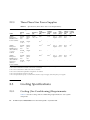
Cooling Specifications
2–8
2–9
2–12
Power Supply to Devices
2–12
2.4.1.1
Single-Phase Power Supply
2.4.1.2
Power Cable Connection Specifications
2.4.1.3
Three-Phase Power Supply
2.4.1.4
Three-Phase Star Power Supply
2–12
2–14
2–17
Circuit Breaker Capacity and Characteristics
2–19
2–21
2.4.2.1
Circuit Breaker Capacity of Customer Panel Board
21
2.4.2.2
Blockade Character of Circuit Breaker
Grounding
1–
1–38
2.1.1
2.4.1
vi
1.2.5.1
2–23
SPARC Enterprise M8000/M9000 Servers Site Planning Guide • September 2007
2–21
2–
Abbreviations
Index
Abbreviations–1
Index–1
Contents
vii
viii
SPARC Enterprise M8000/M9000 Servers Site Planning Guide • September 2007
Figures
FIGURE 1-1
SPARC Enterprise M8000 Server 1–6
FIGURE 1-2
SPARC Enterprise M8000 Server + Power Cabinet 1–7
FIGURE 1-3
SPARC Enterprise M9000 Server (Base Cabinet) 1–8
FIGURE 1-4
SPARC Enterprise M9000 Server (Base Cabinet + Expansion Cabinet) 1–9
FIGURE 1-5
SPARC Enterprise M9000 Server (Base Cabinet + Power Cabinet) 1–10
FIGURE 1-6
SPARC Enterprise M9000 Server (Base Cabinet + Expansion Cabinet + Power Cabinet) 1–
11
FIGURE 1-7
SPARC Enterprise M8000 Server Installation Area 1–12
FIGURE 1-8
SPARC Enterprise M8000 Server + Power Cabinet Installation Area 1–13
FIGURE 1-9
SPARC Enterprise M8000 Server (With an Equipment Rack) Installation Area 1–14
FIGURE 1-10
SPARC Enterprise M8000 Server (With an Equipment Rack) + Power Cabinet Installation
Area 1–15
FIGURE 1-11
SPARC Enterprise M8000 Server (With an Equipment Rack) Installation Area 1–16
FIGURE 1-12
SPARC Enterprise M8000 Server (With an Equipment Rack) + Power Cabinet Installation
Area 1–17
FIGURE 1-13
SPARC Enterprise M9000 Server (Base Cabinet) Installation Area 1–18
FIGURE 1-14
SPARC Enterprise M9000 Server (Base Cabinet) + Power Cabinet Installation Area
FIGURE 1-15
SPARC Enterprise M9000 Server (Base Cabinet + Expansion Cabinet) Installation Area 1–
20
FIGURE 1-16
SPARC Enterprise M9000 Server (Base Cabinet + Expansion Cabinet) + Power Cabinet
Installation Area 1–21
FIGURE 1-17
SPARC Enterprise M8000 Server Bottom View 1–22
1–19
ix
FIGURE 1-18
SPARC Enterprise M8000 Server + Power Cabinet Bottom View 1–23
FIGURE 1-19
SPARC Enterprise M9000 Server (Base Cabinet) Bottom View 1–24
FIGURE 1-20
SPARC Enterprise M9000 Server (Base Cabinet) + Power Cabinet Bottom View 1–25
FIGURE 1-21
SPARC Enterprise M9000 Server (Base Cabinet + Expansion Cabinet) Bottom View 1–26
FIGURE 1-22
SPARC Enterprise M9000 Server (Base Cabinet + Expansion Cabinet) + Power Cabinet
Bottom View 1–27
FIGURE 1-23
SPARC Enterprise M9000 Server (Base Cabinet + Expansion Cabinet) Floor Openings 1–
28
FIGURE 1-24
SPARC Enterprise M9000 Server (Base Cabinet + Expansion Cabinet) + Power Cabinet
Bottom View 1–29
FIGURE 1-25
Cabinet Stabilization Measure: Securing the Device to the Floor Surface 1–32
FIGURE 1-26
Cabinet Stabilization Measure: Securing the Device through a Hole in the Floor 1–33
FIGURE 1-27
XSCF Configuration A (Basic Configuration)
FIGURE 1-28
XSCF Configuration B (Restricted Configuration) 1–36
FIGURE 1-29
XSCF Configuration C (Maximum Configuration) 1–37
FIGURE 1-30
SPARC Enterprise M8000/M9000 Server Connection Schematic Diagram
FIGURE 2-1
Cooling air and exhaust flows of SPARC Enterprise M8000 Server and Rack-mountable Dual
Power Feed 2–10
FIGURE 2-2
Cooling air and exhaust flows of SPARC Enterprise M9000 Server 2–11
FIGURE 2-3
Cooling air and exhaust flows of Power Cabinet 2–11
FIGURE 2-4
Single-Phase Power Supply Connections (SPARC Enterprise M8000 Server) 2–12
FIGURE 2-5
Single-Phase Power Supply Connections (SPARC Enterprise M9000 Server) 2–13
FIGURE 2-6
Three-Phase Delta Power Supply Connections 2–17
FIGURE 2-7
Three-Phase Delta Power Supply Connections 2–18
FIGURE 2-8
Three-Phase Star Power Supply Connections 2–19
FIGURE 2-9
Three-Phase Star Power Supply Connections 2–20
FIGURE 2-10
Circuit Breaker Characteristics of Customers' Power Distribution Boards 2–22
x
1–35
SPARC Enterprise M8000/M9000 Servers Site Planning Guide • September 2007
1–38
Tables
TABLE 1-1
Checklist 1–1
TABLE 1-2
Names and Quantities 1–4
TABLE 1-3
Installation Specifications (External Dimensions and Weights) 1–5
TABLE 1-4
Space Required for Transport
TABLE 2-1
Specifications (Ambient Environmental Requirements)
TABLE 2-2
Recommended Temperature and Humidity Values for Computer Rooms 2–3
TABLE 2-3
Specifications (Allowable Vibration) 2–4
TABLE 2-4
Specifications (Single-Phase Power Requirements) 2–5
TABLE 2-5
Specifications (Three-Phase Delta Power Requirements) 2–7
TABLE 2-6
Specifications (Three-Phase Star Power Requirements) 2–8
TABLE 2-7
Specifications (Cooling and Air-Conditioning Requirements)
TABLE 2-8
Specifications (Single-Phase Power Supply Connections)
TABLE 2-9
Circuit Breaker Capacity of Customer Panel Board 2–21
1–30
2–2
2–9
2–14
xi
xii SPARC Enterprise M8000/M9000 Servers Site Planning Guide • September 2007
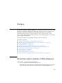
Preface
The SPARC® Enterprise M8000/M9000 server installation planning manual provides
the physical system specifications for this type of server, gives an overview of the
network specifications, and explains other items that need to be considered
beforehand when planning system installation. (These topics include system
environment requirements that must be met for safe system migration as well as the
power supply requirements.)
Carefully read this manual together with the manuals referenced.
This section explains:
■
■
■
■
■
■
■
■
■
■
■
“Structure and Contents of This Manual” on page xiii
“SPARC Enterprise M8000/M9000 Servers Documentation” on page xiv
“Text Conventions” on page xvi
“Prompt Notations” on page xvii
“Syntax of the Command Line Interface (CLI)” on page xvii
“Environment Requirements for Using This Product” on page xviii
“Conventions for Alert Messages” on page xix
“Notes on Safety” on page xx
“Alert Labels” on page xxiii
“Product Handling” on page xxvii
“Fujitsu Siemens Computers Welcomes Your Comments” on page xxviii
Structure and Contents of This Manual
This manual is organized as described below:
■
Chapter 1 Physical and Network Specifications
This chapter provides the physical system specifications and gives an overview
of the network specifications for SPARC Enterprise M8000/M9000 servers.
xiii
■
Chapter 2 Environmental and Electrical Specifications
This chapter describes the system environment requirements that must be met
for safe system migration, as well as the power supply requirements, for
SPARC Enterprise M8000/M9000 servers.
■
Abbreviations
Provides the full spellings of abbreviations used in this manual.
■
Index
Provides keywords and corresponding reference page numbers so that the
reader can easily search for items in this manual as necessary.
SPARC Enterprise M8000/M9000
Servers Documentation
xiv
Book Title
Order No.
SPARC Enterprise M8000/M9000 Servers Site Planning Guide
U41685-J-Z816-x-76
SPARC Enterprise Equipment Rack Mounting Guide
U41711-J-Z816-x-76
SPARC Enterprise M8000/M9000 Servers Getting Started Guide
U41717-J-Z816-x-76
SPARC Enterprise M8000/M9000 Servers Overview Guide
U41686-J-Z816-x-76
Important Safety Information for Hardware Systems
U41715-J-Z816-x-76
SPARC Enterprise M8000/M9000 Servers Safety and Compliance
Guide
U41687-J-Z816-x-76
External I/O Expansion Unit Safety and Compliance Guide
U41716-J-Z816-x-76
SPARC Enterprise M8000/M9000 Servers Unpacking Guide
U41718-J-Z816-x-76
SPARC Enterprise M8000/M9000 Servers Installation Guide
U41688-J-Z816-x-76
SPARC Enterprise M8000/M9000 Servers Service Manual
U41689-J-Z816-x-76
External I/O Expansion Unit Installation and Service Manual
U41679-J-Z816-x-76
SPARC Enterprise M4000/M5000/M8000/M9000 Servers RCI Build
Procedure
U41695-J-Z816-x-76
SPARC Enterprise M4000/M5000/M8000/M9000 Servers
Administration Guide
U41680-J-Z816-x-76
SPARC Enterprise M4000/M5000/M8000/M9000 Servers XSCF
User’s Guide
U41681-J-Z816-x-76
SPARC Enterprise M8000/M9000 Servers Site Planning Guide • September 2007
Book Title
Order No.
SPARC Enterprise M4000/M5000/M8000/M9000 Servers XSCF
Reference Manual
U41682-J-Z816-x-76
SPARC Enterprise M4000/M5000/M8000/M9000 Servers Dynamic
Reconfiguration (DR) User’s Guide
U41684-J-Z816-x-76
SPARC Enterprise M4000/M5000/M8000/M9000 Servers Capacity
on Demand (COD) User’s Guide
U41693-J-Z816-x-76
SPARC Enterprise M4000/M5000/M8000/M9000 Servers RCI User’s
Guide
U41693-J-Z816-x-76
SPARC Enterprise M8000/M9000 Servers Product Notes
U4173x-J-Z816-x-76
External I/O Expansion Unit Product Notes
U41740-J-Z816-x-76
Note – “x” in the order number is the version number of the manual.
1. Manuals on the Web
The latest versions of all the SPARC Enterprise Series manuals are available at the
following website:
http://manuals.fujitsu-siemens.com/
2. Provided in system
Man page of the XSCF
Note – The man page can be referenced on the XSCF shell, and it provides the same
content as the SPARC Enterprise M4000/M5000/M8000/M9000 Servers XSCF Reference
Manual.
3. Solaris Operating System Related Manuals
http://docs.sun.com
Preface
xv
Text Conventions
This manual uses the following fonts and symbols to express specific types of
information.
xvi
Fonts/symbols
Meaning
Example
AaBbCc123
What you type, when contrasted
with on-screen computer output.
This font represents the example of
command input in the frame.
XSCF> adduser jsmith
AaBbCc123
The names of commands, files, and
directories; on-screen computer
output.
This font represents the example of
command input in the frame.
XSCF> showuser -P
User Name:
jsmith
Privileges:
useradm
auditadm
Italic
Indicates the name of a reference
manual
See the XSCF User's Guide.
""
Indicates names of chapters,
sections, items, buttons, or menus
See Chapter 2, "Preparation for
Installation."
SPARC Enterprise M8000/M9000 Servers Site Planning Guide • September 2007
Prompt Notations
The following prompt notations are used in this manual.
Shell
Prompt Notations
XSCF
XSCF>
C shell
machine-name%
C shell super user
machine-name#
Bourne shell and Korn shell
$
Bourne shell and Korn shell
super user
#
OpenBoot PROM
ok
Syntax of the Command Line Interface
(CLI)
The command syntax is as follows:
■
■
■
■
■
A variable that requires input of a value must be enclosed in <>.
An optional element must be enclosed in [ ].
A group of options for an optional keyword must be enclosed in [ ] and delimited
by |.
A group of options for a mandatory keyword must be enclosed in {} and
delimited by |.
The command syntax is shown in a box.
Example:
XSCF> showuser -a
Preface
xvii
Environment Requirements for Using
This Product
This product is a computer that is intended to be used in a computer room.
xviii
SPARC Enterprise M8000/M9000 Servers Site Planning Guide • September 2007
Conventions for Alert Messages
This manual uses the following conventions to show alert messages, which are
intended to prevent injury to the user or bystanders as well as property damage, and
important messages that are useful to the user.
WARNING:
This indicates a hazardous situation that could result in death or serious personal
injury (potential hazard) if the user does not perform the procedure correctly.
CAUTION:
This indicates a hazardous situation that could result in minor or moderate personal
injury if the user does not perform the procedure correctly. This signal also indicates
that damage to the product or other property may occur if the user does not perform
the procedure correctly.
IMPORTANT:
This indicates information that could help the user to use the product more
effectively.
Alert messages in the text
An alert message in the text consists of a signal indicating an alert level followed by
an alert statement. Alert messages are indented to distinguish them from regular
text. Also, a space of one line precedes and follows an alert statement.
WARNING:
The tasks listed below for this product and optional product provided by Fujitsu
Siemens Computers should be performed only by authorized service personnel.
The user must not perform these tasks. Incorrect operation of these tasks may cause
electric shock, injury, or fire.
■
■
■
■
■
Installation and reinstallation of all components
Removal of front, rear, or side covers
Mounting/unmounting of optional internal devices
Connecting/disconnecting of external interface cables
Maintenance (repair and regular diagnosis and maintenance)
Also, important alert messages are shown in “Important Alert Messages” on
page xx.
Preface
xix
Notes on Safety
Important Alert Messages
This manual provides the following important alert signals:
Caution – The WARNING signal indicates a dangerous situation could result in
death or serious injury if the user does not perform the procedure correctly.
Task
Warning
Normal
operation
Electric shock, fire
Do not damage, break, or modify the power cables. Cable damage may
cause electric shock or fire.
xx SPARC Enterprise M8000/M9000 Servers Site Planning Guide • September 2007
Caution – The CAUTION signal indicates a hazardous situation could result in
minor or moderate personal injury if the user does not perform the procedure
correctly. This signal also indicates that damage to the product or other property
may occur if the user does not perform the procedure correctly.
Task
Warning
Normal
operation
Equipment damage
Be sure to follow the precautions below when installing the main unit.
Otherwise, the equipment may be damaged.
• Do not block ventilation slits.
• Avoid installing the equipment in a placed exposed to direct sunlight or
near equipment that becomes extremely hot.
• Avoid installing the equipment in a dusty place or a place directly
exposed to corrosive gas or salty air.
• Avoid installing the equipment in a placed exposed to strong vibration.
Also, install the equipment on a level surface so that it is stable.
• The grounding wire must be class 3 or higher. Connecting it with
another grounding wire for shared grounding may cause a malfunction.
Be sure to use a single grounding path for the grounding wire.
• Do not run any cable beneath any equipment. Also, prevent cables from
becoming taut. Never disconnect any power cable from the equipment
while power is being supplied to the equipment.
• Do not place anything on top of the main unit. Do not use the main unit
as a workspace.
• Avoid exposing the equipment to rapid changes in the ambient
temperature, such as a rapid increase during transport in winter. A
rapid increase in the ambient temperature causes moisture to condense
in the equipment. Use the equipment only after the difference between
its temperature and the ambient temperature is negligible.
• Avoid installing the equipment near a copy machine, air conditioner, or
welding machine, which is noisy.
• Take preventive action to minimize static electricity at the installation
location. Note that static electricity is easily generated in some carpets
and can cause the equipment to malfunction.
• Confirm that the power supply voltage and frequency during operation
match the rated values indicated on the equipment.
• Do not insert any object into an opening in the equipment. Components
inside the equipment use high voltage. Conductive foreign matter, such
as a metal object, inserted into the equipment, may cause a short circuit
between components, resulting in fire, electric shock, or equipment
damage.
• For maintenance of the equipment, contact your authorized service
personnel.
Preface
xxi
Task
Warning
Normal
operation
Data destruction
Confirm the items listed below before turning off the power. Otherwise,
data may be destroyed.
• All applications have completed processing.
• No user is using the equipment.
• When the main unit power is turned off, the Power LED on the
operation panel is turned off. Be sure to confirm that the Power LED is
off before turning off the main power (uninterruptible power supply
[UPS], power distribution box, main line switch, etc.).
If necessary, back up files before turning off the system power.
Data destruction
Do not forcibly stop a domain that is operating normally. Otherwise, data
may be destroyed.
Data destruction
Do not disconnect the power cable from the AC power input while power
is being supplied. Otherwise, data stored on hard disk units may be
destroyed.
xxii SPARC Enterprise M8000/M9000 Servers Site Planning Guide • September 2007
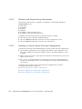
Alert Labels
The labels shown below are affixed on this product. These labels provide
information for users of the product:
Caution – Do not peel off the labels.
■
SPARC Enterprise M8000 Server
SPARC Enterprise M8000 Server (Front View)
Preface
xxiii
■
SPARC Enterprise M9000 Server
SPARC Enterprise M9000 Server (Front View)
xxiv
SPARC Enterprise M8000/M9000 Servers Site Planning Guide • September 2007
SPARC Enterprise M9000 Server (Rear View)
Preface
xxv
SPARC Enterprise M9000 Server with Expansion Cabinet (Rear View)
xxvi
SPARC Enterprise M8000/M9000 Servers Site Planning Guide • September 2007
Product Handling
Maintenance
Caution – Certain tasks in this manual should only be performed by a certified
service engineer. User must not perform these tasks. Incorrect operation of these
tasks may cause electric shock, injury, or fire.
■
Installation and reinstallation of all components, and initial settings
■
Removal of front, rear, or side covers
■
Mounting/de-mounting of optional internal devices
■
Plugging or unplugging of external interface cards
■
Maintenance and inspections (repairing, and regular diagnosis and maintenance)
Caution – The following tasks regarding this product and the optional products
provided from Fujitsu Siemens Computers should only be performed by a certified
service engineer. Users must not perform these tasks. Incorrect operation of these
tasks may cause malfunction.
■
Unpacking optional adapters and such packages delivered to the users
■
Plugging or unplugging of external interface cards
Remodeling/Rebuilding
Caution – Any modification and/or recycling of this product and its components
may be carried out only by a certified service engineer and must not be done by the
customer under any circumstances.
Otherwise, electric shock, injury or fire may result.
Preface
xxvii
Emission of Laser Beam (Invisible)
Caution – The main unit and high-speed optical interconnect cabinet contain
modules that generate invisible laser radiation.
Laser beams are generated while the equipment is operating, even if an optical cable
is disconnected or a cover is removed.
Do not look at any light-emitting part directly or through an optical apparatus (e.g.,
magnifying glass, microscope).
Fujitsu Siemens Computers Welcomes
Your Comments
We would appreciate your comments and suggestions to improve this document.
You can submit your comments by using “Reader's Comment Form” on page xxix.
xxviii SPARC Enterprise M8000/M9000 Servers Site Planning Guide • September 2007
Reader's Comment Form
Preface
xxix
FOLD AND TAPE
NO POSTAGE
NECESSARY
IF MAILED
IN THE
UNITED STATES
BUSINESS REPLY MAIL
FIRST-CLASS MAIL PERMIT NO 741 SUNNYVALE CA
POSTAGE WILL BE PAID BY ADDRESSEE
FUJITSU COMPUTER SYSTEMS
AT TENTION ENGINEERING OPS M/S 249
1250 EAST ARQUES AVENUE
P O BOX 3470
SUNNYVALE CA 94088-3470
FOLD AND TAPE
xxx SPARC Enterprise M8000/M9000 Servers Site Planning Guide • September 2007
CHAPTER
1
Physical and Network
Specifications
This chapter describes what the reader is expected to know, including physical and
network connection specifications for the SPARC® Enterprise M8000/M9000 Servers,
before planning server installation.
This chapter contains the following sections:
1.1
■
Section 1.1, “Before Setting Up the System” on page 1-1
■
Section 1.2, “Physical Specifications” on page 1-4
Before Setting Up the System
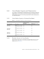
Before starting server installation, verify that the requirements listed in TABLE 1-1 are
satisfied.
TABLE 1-1
Checklist (1 of 3)
Requirements
Item
Check
System components
Have the server components been decided?
❏
Has the total number of servers been decided?
❏
Have the system administrators and operators taken the required Sun
Microsystems or Fujitsu training courses?
❏
System management
1-1
TABLE 1-1
Checklist (2 of 3)
Requirements
Item
Check
Physical specifications
Has the server installation location been decided?
❏
Does the installation floor layout satisfy the ventilation and maintenance
access requirements?
See Section 1.2.2, “System Installation (Space)” on page 1-12
❏
Does the device layout guarantee that heated air vented from one
component does not enter an air intake of another component?
See Section 1.2.2, “System Installation (Space)” on page 1-12
❏
Does the access route provide sufficient space for transport of the packed
devices? Have you confirmed that all route incline angles are within the
permitted range?
See Section 1.2.3, “Planning Your Access Route” on page 1-30
❏
If a pallet jack is to be used, have you confirmed that the device weight is
within the load limit of the pallet jack?
See Section 1.2.3, “Planning Your Access Route” on page 1-30
❏
If an elevator is to be used, have you confirmed that the elevator car is
wide enough for the device to be carried into it and that the device
weight is within the load limit of the elevator?
See Section 1.2.3, “Planning Your Access Route” on page 1-30
❏
Stabilizing the cabinet
Have cabinet stabilization measures been considered?
See Section 1.2.4, “Cabinet Stabilization Measures” on page 1-31
❏
Network specification
Do you clearly understand what data connections and feeds are required
for system startup and network connections?
See Section 1.2.5, “Planning Your Network Connection” on page 1-33
❏
Environmental
Does the computer room air handling meet temperature and humidity
requirements?
See Section 2.1, “Environmental Requirements” on page 2-1
❏
Can the computer room continuously satisfy environmental
requirements?
❏
Is the computer room adequately equipped to extinguish a fire?
❏
Is the computer room secured?
❏
Planning your access
route
1-2
SPARC Enterprise M8000/M9000 Servers Site Planning Guide • September 2007
TABLE 1-1
Checklist (3 of 3)
Requirements
Item
Check
Facility power
Do you know the required operating voltages and electrical current
levels of the device and peripherals?
See Section 2.2, “Electrical Specifications” on page 2-4
❏
Are enough power outlets provided for the server cabinet, monitors, and
peripherals?
❏
Are the circuit breakers for the device suitable in terms of voltage and
current-carrying capacities?
See Section 2.4, “Facility Power Requirements” on page 2-12
❏
If you use single-phase power feed, is a power outlet located within 3.0
meters (9.8 feet) of the device?
❏
Chapter 1
Physical and Network Specifications
1-3
1.2
Physical Specifications
This section outlines the SPARC Enterprise M8000/M9000 Server components and
lists their physical specifications.
1.2.1
System Components
1.2.1.1
Names and Corresponding Capacities and Functions
TABLE 1-2 lists the names and the capacities and functions of the SPARC Enterprise
M8000/M9000 Server components.
TABLE 1-2
Names and Quantities
Name
Capacity/function
SPARC Enterprise
M8000 Server
Accommodates up to four CMUs (up to 16 CPU
modules: 32 cores) and up to four IOUs.
SPARC Enterprise
M9000 Server (base
cabinet)
Accommodates up to eight CMUs (up to 32 CPU
modules: 64 cores) and up to eight IOUs.
SPARC Enterprise
M9000 Server
(expansion cabinet)
Accommodates up to eight CMUs (up to 32 CPU
modules: 64 cores) and up to eight IOUs.
Rack-mountable
Dual Power Feed
Provides power redundancy (with single-phase dual
power feed) for a SPARC Enterprise M8000 Server
server. It is a rack-mount type.
Optional.
Power Cabinet
There are two types of Power Cabinet:
• Device that provides three-phase dual power feed for
a SPARC Enterprise M8000 Server
• Device that provides single-phase dual power feed or
three-phase dual power feed for a SPARC Enterprise
M9000 Server
One power cabinet is required
for each SPARC Enterprise
M8000 Server.
One power cabinet is required
for each SPARC Enterprise
M9000 Server of the base or
expansion cabinet type. (The
device that provides singlephase dual power feed is an
optional product for the
SPARC Enterprise M9000
Server.)
1-4
Remarks
Can accommodate up to 16
CMUs (up to 64 CPU
modules: 128 cores) and up to
16 IOUs when combined with
an expansion cabinet.
SPARC Enterprise M8000/M9000 Servers Site Planning Guide • September 2007
1.2.1.2
External Dimensions and Weights
TABLE 1-3 lists the external dimensions and weights of the SPARC Enterprise
M8000/M9000 server cabinet.
TABLE 1-3
Installation Specifications (External Dimensions and Weights)
External dimensions [mm (inch)]
Name
Width
Depth
Height
Weight [kg]
SPARC Enterprise
M8000 Server
750 (29.5)
1260 (49.6)
1800 (70.9)
700
1
M8000 + Power
Cabinet
1054 (41.5)
1260 (49.6)
1800 (70.9)
1020
1
SPARC Enterprise
M9000 Server (base
cabinet)
850 (33.5)
1260 (49.6)
1800 (70.9)
940
M9000 (base
cabinet) + Power
Cabinet
1154 (45.4)
1260 (49.6)
1800 (70.9)
1290
M9000 (base
cabinet + expansion
cabinet)
1674 (65.9)
1260 (49.6)
1800 (70.9)
1880
2
M9000 (base
cabinet + expansion
cabinet) + Power
Cabinet
2282 (89.8)
1260 (49.6)
1800 (70.9)
2580
2
Rack-mountable
Dual Power Feed
489 (19.3)
1003 (39.5)
278 (10.9)
[6U]
75
3
Power Cabinet
317 (12.5)
1244 (49.0)
1800 (70.9)
350
4
1 The weight of SPARC Enterprise M8000 Server does not include weight of those mounted on the equipment rack part.
2 When combining an SPARC Enterprise M9000 Server base cabinet and an M9000 Server expansion cabinet, the width of each cabinet is 837 mm (including the side panel on one side).
3 The Rack-mountable Dual Power Feed is a device of the rack-mount type, and it can be mounted only on the equipment rack.
4 The width of a Power Cabinet includes the dimension of the side panel on one side.
Chapter 1
Physical and Network Specifications
1-5
1.2.1.3
System Appearance
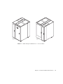
FIGURE 1-1 to FIGURE 1-6 show the appearance of the server components and the
associated servers in their maximum configuration.
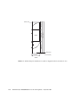
SPARC Enterprise M8000 Server Appearance
Front
Rear
FIGURE 1-1
1-6
SPARC Enterprise M8000 Server
SPARC Enterprise M8000/M9000 Servers Site Planning Guide • September 2007
Front
Rear
FIGURE 1-2
SPARC Enterprise M8000 Server + Power Cabinet
Chapter 1
Physical and Network Specifications
1-7
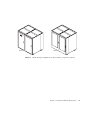
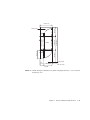
SPARC Enterprise M9000 Server Appearance
Front
Rear
FIGURE 1-3
1-8
SPARC Enterprise M9000 Server (Base Cabinet)
SPARC Enterprise M8000/M9000 Servers Site Planning Guide • September 2007
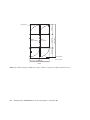
Front
Rear
FIGURE 1-4
SPARC Enterprise M9000 Server (Base Cabinet + Expansion Cabinet)
Chapter 1
Physical and Network Specifications
1-9
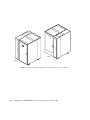
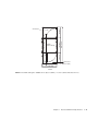
Rear
Front
FIGURE 1-5
1-10
SPARC Enterprise M9000 Server (Base Cabinet + Power Cabinet)
SPARC Enterprise M8000/M9000 Servers Site Planning Guide • September 2007
Front
Rear
FIGURE 1-6
SPARC Enterprise M9000 Server (Base Cabinet + Expansion Cabinet + Power Cabinet)
Chapter 1
Physical and Network Specifications
1-11
1.2.2
System Installation (Space)
1.2.2.1
Size and Space Specifications
Before starting to assemble a SPARC Enterprise M8000/M9000 Servers installation,
secure a service area (maintenance area) that is large enough for each device
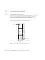
(cabinet) plus required service access space for each component. FIGURE 1-7 to
FIGURE 1-16 show the space required for installation of each server.
SPARC Enterprise M8000 Server Installation Area
1260 (49.6)
800 (31.5)
M8000
2860 (112.6)
800 (31.5)
Service area
Service area
750(29.5)
Unit: mm (inch)
Front
FIGURE 1-7
1-12
SPARC Enterprise M8000 Server Installation Area
SPARC Enterprise M8000/M9000 Servers Site Planning Guide • September 2007
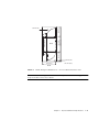
1260 (49.6)
2860 (112.6)
M8000
800 (31.5)
Power Cabinet
800 (31.5)
Service area
Service area
1054 (41.5)
Unit: mm (inch)
Front
FIGURE 1-8
SPARC Enterprise M8000 Server + Power Cabinet Installation Area
Note – Before mounting units in an SPARC Enterprise M8000 Server equipment
rack, secure the service areas shown.
Chapter 1
Physical and Network Specifications
1-13
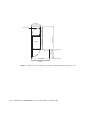
750 (29.5)
1260 (49.6)
M8000
2860 (112.6)
800 (31.5)
Service area
800 (31.5)
Service area
1550 (61.0)
Unit: mm (inch)
Front
FIGURE 1-9
1-14
SPARC Enterprise M8000 Server (With an Equipment Rack) Installation Area
SPARC Enterprise M8000/M9000 Servers Site Planning Guide • September 2007
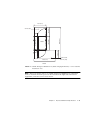
1054 (41.5)
2860 (112.6)
800 (31.5)
M8000
1260 (49.6)
Power Cabinet
800 (31.5)
Service area
Service area
Unit: mm (inch)
1854 (73.0)
Front
FIGURE 1-10
SPARC Enterprise M8000 Server (With an Equipment Rack) + Power Cabinet
Installation Area
Note – Before mounting units in an SPARC Enterprise M8000 Server equipment
rack at a location where no space can be secured on the right side of the server
equipment, secure the service areas shown.
Chapter 1
Physical and Network Specifications
1-15
1260 (49.6)
1200 (47.2)
M8000
3260 (128.3)
800 (31.5)
Service area
Service area
750 (29.5)
Unit: mm (inch)
Front
FIGURE 1-11
1-16
SPARC Enterprise M8000 Server (With an Equipment Rack) Installation Area
SPARC Enterprise M8000/M9000 Servers Site Planning Guide • September 2007
1054 (41.5)
1200 (47.2)
3260 (128.3)
1260 (49.6)
M8000
800 (31.5)
Power Cabinet
800 (31.5)
Service area
Service area
317
(12.5)
737 (29.0)
Unit: mm (inch)
Front
FIGURE 1-12
SPARC Enterprise M8000 Server (With an Equipment Rack) + Power Cabinet
Installation Area
Chapter 1
Physical and Network Specifications
1-17
SPARC Enterprise M9000 Server Installation Area
1260 (49.6)
900 (35.4)
M9000
(Base Cabinet)
3060 (128.3)
900 (35.4)
Service area
Service area
850 (33.4)
Unit: mm (inch)
Front
FIGURE 1-13
1-18
SPARC Enterprise M9000 Server (Base Cabinet) Installation Area
SPARC Enterprise M8000/M9000 Servers Site Planning Guide • September 2007
3060 (128.3)
1260 (49.6)
M9000
(Base Cabinet)
900 (35.4)
Power Cabinet
900 (35.4)
Service area
317
(12.5)
Service area
837 (33.0)
1154 (45.3)
Unit: mm (inch)
Front
FIGURE 1-14
SPARC Enterprise M9000 Server (Base Cabinet) + Power Cabinet Installation Area
Chapter 1
Physical and Network Specifications
1-19
3060 (128.3)
M9000
(Ex. Cabinet)
900 (35.4)
M9000
(Base Cabinet)
1260 (49.6)
900 (35.4)
Service area
Service area
837 (33.0)
Unit: mm (inch)
1674 (65.9)
Front
FIGURE 1-15
1-20
SPARC Enterprise M9000 Server (Base Cabinet + Expansion Cabinet) Installation Area
SPARC Enterprise M8000/M9000 Servers Site Planning Guide • September 2007
3060 (128.3)
1260 (49.6)
M9000
(Ex. Cabinet)
900 (35.4)
M9000
(Base Cabinet)
Power Cabinet
Power Cabinet
900 (35.4)
Service area
317
(12.5)
Service area
824 (32.4)
Unit: mm (inch)
2282 (89.8)
Front
FIGURE 1-16
SPARC Enterprise M9000 Server (Base Cabinet + Expansion Cabinet) + Power Cabinet
Installation Area
Chapter 1
Physical and Network Specifications
1-21
1.2.2.2
Bottom Views of the Components
FIGURE 1-17 to FIGURE 1-22 show the bottom of the SPARC Enterprise M8000/M9000
Servers components, such as the openings for laying cables, air inlet ports used for
cooling, legs, and casters.
The values indicated are layout values of the rack. If its feet are fixed to the floor,
size difference (±2mm) must be take into consideration to designate its location.
SPARC Enterprise M8000 Server Bottom View
Caster
Feet
Opening for cables
inlet and outlet
Opening for air inlet
Unit: mm (inch)
Front
FIGURE 1-17
1-22
SPARC Enterprise M8000 Server Bottom View
SPARC Enterprise M8000/M9000 Servers Site Planning Guide • September 2007
Caster
Feet
Opening for cables
inlet and outlet
Opening for air inlet
Front
FIGURE 1-18
Unit: mm (inch)
SPARC Enterprise M8000 Server + Power Cabinet Bottom View
Chapter 1
Physical and Network Specifications
1-23
SPARC Enterprise M9000 Server Bottom View
Caster
Feet
Opening for cables
inlet and outlet
Opening for air inlet
Unit: mm (inch)
Front
FIGURE 1-19
1-24
SPARC Enterprise M9000 Server (Base Cabinet) Bottom View
SPARC Enterprise M8000/M9000 Servers Site Planning Guide • September 2007
Caster
Feet
Opening for cables
inlet and outlet
Front
Opening for air inlet
Unit: mm (inch)
FIGURE 1-20
SPARC Enterprise M9000 Server (Base Cabinet) + Power Cabinet Bottom View
Chapter 1
Physical and Network Specifications
1-25
Front
Caster
Feet
Opening for cables
inlet and outlet
Opening for air inlet
Unit: mm (inch)
FIGURE 1-21
1-26
SPARC Enterprise M9000 Server (Base Cabinet + Expansion Cabinet) Bottom View
SPARC Enterprise M8000/M9000 Servers Site Planning Guide • September 2007
Front
Caster
Feet
Opening for cables
inlet and outlet
Opening for air inlet
Unit: mm (inch)
FIGURE 1-22
SPARC Enterprise M9000 Server (Base Cabinet + Expansion Cabinet) + Power Cabinet Bottom
View
Chapter 1
Physical and Network Specifications
1-27
1.2.2.3
Free-Access Floor Openings for Underfloor Air-Conditioning
Use underfloor air conditioning to cool the SPARC Enterprise M9000 Server (with an
extended cabinet).
To use underfloor air conditioning, air-conditioning openings must be provided on
the free-access floor under the cabinet. Provide appropriate floor openings by
considering the air conditioning capacities required for the cabinet, the floor
strength, and the locations of the leveling feet. FIGURE 1-23 and FIGURE 1-24 show
examples of appropriate floor openings.
Front
Caster
Feet
Opening for air conditioning from the bottom
(The opening should be in the shaded freeaccess area. It can’t be shared with the opening for cables out.)
Unit: mm (inch)
FIGURE 1-23
1-28
SPARC Enterprise M9000 Server (Base Cabinet + Expansion Cabinet) Floor Openings
SPARC Enterprise M8000/M9000 Servers Site Planning Guide • September 2007
Front
Caster
Feet
Opening for air conditioning from the
bottom
(The opening should be in the shaded
free-access area. It can’t be shared
with the opening for cables out.)
Unit: mm (inch)
FIGURE 1-24
1.2.2.4
SPARC Enterprise M9000 Server (Base Cabinet + Expansion Cabinet) + Power Cabinet Bottom
View
Ceiling Height
The minimum ceiling height for the SPARC Enterprise M8000/M9000 Server is 2.3m
(7.5 feet), measured from the true floor or a raised floor, whichever is higher. The
space above the server and its surroundings must not restrict the movement of
cooling air between the air conditioner and the server.
Chapter 1
Physical and Network Specifications
1-29
1.2.3
Planning Your Access Route
This section describes necessary considerations before you move the server to its
installation destination.
1.2.3.1
Space Required for System Transport
The access route must satisfy the requirements listed in TABLE 1-4.
Each cabinet is packed with simple packaging or in a wood-framed case for shipping
of the server. If it is difficult to carry the packed cabinet to the installation
destination, remove the packing materials, front and rear doors, side panels, and/or
other parts as necessary.
If the cabinet weight exceeds the minimum withstand load for the transport
equipment used, you can move the cabinet with its PSU and FAN (about 4 kg each)
removed.
TABLE 1-4
SPARC
Enterprise
M8000 Server
1-30
Minimum
door height
[mm (inch)]
Minimum
door width
[mm (inch)]
Minimum
passage
width [mm
(inch)]
Minimum
elevator car
depth [mm
(inch)]
Minimum
withstand
load of
transport
equipment
[kg] 3
Simple
packaging1
1900 (74.8)
1000 (39.4)
1200 (47.2)
1500 (59.0)
820
10
Without
front and
rear doors
or side
panels
1900 (74.8)
800 (31.5)
1000 (39.4)
1350 (53.1)
690
10
Tri-Wall2
2100 (82.7)
1800 (70.9)
1800 (70.9)
1100 (43.3)
830
10
Wooden2
packing
2100 (82.7)
1900 (74.8)
1900 (74.8)
1100 (43.3)
980
10
Device
status
during
transport
Name
Space Required for Transport (1 of 2)
1
SPARC Enterprise M8000/M9000 Servers Site Planning Guide • September 2007
Maximum
inclination
of access
route [˚ ]
TABLE 1-4
Name
SPARC
Enterprise
M9000 Server
(Base cabinet)
(Expansion
cabinet)
Space Required for Transport (2 of 2)
Minimum
door height
[mm (inch)]
Minimum
door width
[mm (inch)]
Minimum
passage
width [mm
(inch)]
Minimum
elevator car
depth [mm
(inch)]
Minimum
withstand
load of
transport
equipment
[kg] 3
Simple
packaging1
1900 (74.8)
1100 (43.3)
1300 (51.2)
1500 (59.0)
950
10
Without
front and
rear doors
or side
panels
1900 (74.8)
900 (35.4)
1100 (43.3)
1350 (53.1)
820
10
Tri-Wall2
2100 (82.7)
1800 (70.9)
1800 (70.9)
1200 (47.2)
1050
10
Wooden2
2100 (82.7)
1800 (70.9)
1800 (70.9)
1200 (47.2)
1100
10
Simple
packaging1
1900 (74.8)
700 (27.6)
900 (35.4)
1500 (59.0)
350
10
Without
front and
rear doors
or side
panels
1900 (74.8)
700 (27.6)
900 (35.4)
1350 (53.1)
320
10
Tri-Wall2
2100 (82.7)
1600 (63.0)
1600 (63.0)
1200 (47.2)
450
10
Wooden2
2100 (82.7)
1700 (67.0)
1700 (67.0)
1200 (47.2)
500
10
Device
status
during
transport
1
Maximum
inclination
of access
route [˚ ]
packing
Power Cabinet
packing
1 Simple packaging means a device is covered only with a packing material such as a vinyl sheet instead of being packed in a woodframed case or a cardboard box.
2 When in Tri-wall and wooden packing, use the pallet jack to move the equipment.
3 The transport equipment includes the elevator and pallet jack used to transport the device.
1.2.3.2
Other Considerations
Confirm that the access route is free of any steps and other obstacles that would
expose the device to shock.
1.2.4
Cabinet Stabilization Measures
This section shows useful methods of securing a SPARC Enterprise M8000/M9000
server to prevent it from shifting due to vibration.
Chapter 1
Physical and Network Specifications
1-31
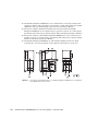
Method of Securing the Device To the Floor Surface
(Example of securing the SPARC Enterprise M9000 Server in place)
850 (33.5)
1260 (49.6)
171
(6.7)
Fixing bracket
Caster
175
(6.9)
Feet
66 (2.6)
99 (3.9)
99 (3.9)
66 (2.6)
Unit: mm (inch)
Front
Fixing bracket: C230-4130-X514
Bushing: C230-4080-X003
Metal washer: F6-WB12-121
Metal washer: F6-WM12-121
Bolt: F6-B12-***121 (Bolt diameter: M12)
(Floor)
A-A cross-section
*** = Bolt length (mm)
The bolt length must be specified here.
Note: Consult with the company that constructed the building because the length
depends on the structure of the building.
FIGURE 1-25
1-32
Cabinet Stabilization Measure: Securing the Device to the Floor Surface
SPARC Enterprise M8000/M9000 Servers Site Planning Guide • September 2007
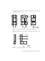
Method of Securing the Device Through a Hole in the Floor
(Device)
Change this board leg
(height adjustment leg) to the
"F6-DA6G" and tighten the
bolt from under the floor.
Bolt diameter: M20
Bolt length: 15 mm + floor
thickness
(Floor)
FIGURE 1-26
1.2.5
Note: Consult with the company that constructed the
building because the length
depends on the structure of
the building.
Cabinet Stabilization Measure: Securing the Device through a Hole in the
Floor
Planning Your Network Connection
This section provides an overview for starting the SPARC Enterprise M8000/M9000
server network required for system startup and network connections.
For details on the connections, see the SPARC Enterprise M8000/M9000 Servers
Installation Guide.
1.2.5.1
Setup and Network Connections
The serial port of the eXtended System Control Facility Unit (XSCFU) is used for the
following purposes:
■
Connecting a local area network (LAN) port to the system administration
network
■
Monitoring the boot process
■
Changing the initial values of the system controller
The administration network connects the XSCFU to the system administrator's
management console. A direct connection can be used for this purpose. However,
the connection is usually one through a hub or switch specific to the system control
network. To initialize a LAN port, direct administration of the serial port must be
performed.
Chapter 1
Physical and Network Specifications
1-33
1.2.5.2
Platform and Domain Setup Information
The following information is required for installation of the SPARC Enterprise
M8000/M9000 servers:
■
■
■
■
■
■
Host name
IP address
Domain
Netmask
IP address of the network gateway
IP address of the network name server
In addition, the following network connections must be available:
■
■
■
1.2.5.3
One serial console connection (9600 baud, N81)
One 10/100BASE-T Ethernet connection for SCF (connected to Port 0)
One 10/100BASE-T Ethernet connection for each domain
Selecting a System Control Network Configuration
Consider the following when determining the system control network configuration:
■
An IP address appropriate to the existing environment can be assigned to each
LAN port, and the Class B private address, which is the default address, can be
changed.
■
Either dual power feed or single power feed must be selected for the power feed
option of your server.
■
Do you have a separate LAN port or network for access by a field engineer? If
not, does the field engineer have access through the serial port when maintenance
is necessary?
Generally, there are three server control network configurations as follows,
according to installation conditions:
1-34
■
XSCF Configuration A (Basic Configuration)
■
XSCF Configuration B (Restricted Configuration)
■
XSCF Configuration C (Maximum Configuration)
SPARC Enterprise M8000/M9000 Servers Site Planning Guide • September 2007
XSCF Configuration A (Basic Configuration)
Only one of the two LAN ports is used. The serial port and the other LAN port are
reserved so that they can be used as maintenance ports. The same switch is used for
system administration and the remote service. Consequently, any failure of the
switch causes a failure of the server control network.
ETHERNET #0 ETHERNET #1
Switch
Serial port
Remote service
Firewall
System administration
FIGURE 1-27
XSCF Configuration A (Basic Configuration)
Chapter 1
Physical and Network Specifications
1-35
XSCF Configuration B (Restricted Configuration)
(Restricted redundancy) - Both LAN ports are used. One port is used for system
administration, and the other is used for the remote message function. If one switch
fails, errors can be reported. The serial port and port for the remote service switch
can be used as maintenance ports.
ETHERNET
#0
Switch
Maintenance port
ETHERNET
#1
Serial port
Switch
System administration
Remote service
Firewall
FIGURE 1-28
1-36
XSCF Configuration B (Restricted Configuration)
SPARC Enterprise M8000/M9000 Servers Site Planning Guide • September 2007
XSCF Configuration C (Maximum Configuration)
(Maximum redundancy) - Both LAN ports are used. Each switch has maintenance
ports, which are used for the remote service or system administration. The switches
are connected for failure management and system administration.
If a switch fails, no interrupt occurs in the system control network.
ETHERNET
#0
ETHERNET
#1
Serial port
Switch
Switch
System administration
Remote service
Firewall
Maintenance port
FIGURE 1-29
XSCF Configuration C (Maximum Configuration)
Chapter 1
Physical and Network Specifications
1-37
1.2.5.4
Interface Cable Connections
SPARC Enterprise Server Connection Schematic Diagram
Basic
equipment
M8000/M9000
LAN port (x2)
Serial port
XSCFU (x2)
USB
RCI-IF
Option
10BASET/100BASETX
Serial interface
USB device (maintenance port)
RCI interface
(external power supply control unit)
IOU (M8000: Max4)
(M9000: MAx16)
PCI card x8
UPC interface (x2)
FIGURE 1-30
1-38
SCSI/LAN/WAN interface
Fibre Channel
Serial Adapter
Uninterruptible power supply
SPARC Enterprise M8000/M9000 Server Connection Schematic Diagram
SPARC Enterprise M8000/M9000 Servers Site Planning Guide • September 2007
CHAPTER
2
Environmental and Electrical
Specifications
This chapter explains environmental and electrical power supply specifications and
conditions necessary for stable system operation:
■
Environmental Requirements
■
Electrical Specifications
■
Cooling Specifications
■
Facility Power Requirements
2.1
Environmental Requirements
2.1.1
Ambient Environmental Requirements
The SPARC Enterprise M8000/M9000 Server must satisfy the ambient environmental
requirements listed in TABLE 2-1.
2-1
TABLE 2-1
Specifications (Ambient Environmental Requirements)
Temperature [˚C (˚F)]1
Humidity [%RH]1
System name
Operating
Non-operating
Operating
Non-operating
SPARC
Enterprise
M8000
Server
5 to 32 (41 to 89.6) at an installation altitude
ranging from 0 to less than 1,500 m (4921 feet)
above sea level
5 to 30 (41 to 86) at an installation altitude
ranging from 1500 m (4921 feet) to less than 2000
m (6562 feet) above sea level
5 to 28 (41 to 82.4) at an installation altitude
ranging from 2000 m (6562 feet) to less than 2500
m (8202 feet) above sea level
5 to 26 (41 to 78.8) at an installation altitude
ranging from 2500 m (8202 feet) to 3000 m (9843
feet) above sea level
0 to 50
(32 to 122)
20 to 80
8 to 80
and
SPARC
Enterprise
M9000
Server
1 Noncondensing.
2.1.2
Recommended Ambient Temperature and
Humidity
Keep the temperature in the computer room at a comfortable temperature for people
or slightly lower. At this temperature level, inadequate cooling of parts of the
computer room due to the heat generated by a device or to trapped hot air can be
prevented, reducing related adverse effects on each device in the entire system
configuration.
Also, if an air conditioning failure occurs, there is sufficient time available before the
temperature reaches the upper limit.
Special consideration must be paid to humidity if underfloor ventilation is used.
Normally, air contains water vapor. Relative humidity, which is indicated as a
percentage (%) of the total amount of water vapor that can exist in the air without
condensing, is inversely proportional to air temperature; it goes down when the
temperature rises, and goes up when the temperature drops.
For example, air with a relative humidity of 45% at a temperature of 24˚C (75˚F) has
a relative humidity of 65% at a temperature of 18˚C (64˚F); and if the temperature
drops farther, the relative humidity rises to more than 65%, eventually to condense
out as water droplets.
2-2
SPARC Enterprise M8000/M9000 Servers Site Planning Guide • September 2007
Air conditioning facilities usually do not provide functions to precisely monitor and
control the temperature and humidity throughout an entire computer room.
Generally, computer room air conditioning controls the temperature and humidity
according to the monitoring data at individual points corresponding to multiple
exhaust vents in the main unit and other units in the room. However, since air
conditioning facilities for underfloor ventilation perform such control according to
the monitoring data at each point close to an exhaust vent, the distribution of the
temperature and humidity across the entire computer room is uneven.
TABLE 2-2 lists the recommended temperature and humidity values for computer
rooms.
Recommended Temperature and Humidity Values for Computer Rooms
TABLE 2-2
Point close to underfloor exhaust vent
Temperature
Air conditioning
method
Humidity %
˚C
˚F
Direct
blowing or
duct blowing
-
-
Underfloor
ventilation
18 ±1
Direct
blowing or
using duct
blowing and
underfloor
ventilation
together
18 ±1
Monitoring and control point in room
Temperature
Remarks
Humidity %
˚C
˚F
-
24 ±2
75 ±4
45 ±5
-
64 ±2
65 ±5
Target
temperature
of 24˚C
Target
temperature
of 75˚F
About
45% at
24˚C
The room
temperature
and humidity
fluctuate,
without
control,
according to
the thermal
load in the
room.
64 ±2
65 ±5
24 ±2
75 ±4
45 ±5
-
Chapter 2
Environmental and Electrical Specifications
2-3
2.1.3
Vibration Requirements
The allowable vibration in the SPARC Enterprise M8000/M9000 servers are listed in
TABLE 2-2.
TABLE 2-3
Specifications (Allowable Vibration)
Allowable vibration [gal]
System name
Operating
SPARC
Enterprise
M8000 Server
SPARC
Enterprise
M9000 Server
250
1
Non-Operating
400
1, 2
1 Allowable vibration (Sun standard) for synthetic seismic vibration
2 The value for non-operation is applicable when vibration-proofing measures are taken for the leveling feet.
2.2
Electrical Specifications
SPARC Enterprise M8000/M9000 Servers can use two types of power supply: singlephase power and three-phase power. Redundant power cables are supported only
on servers that have the dual power feed option. The dual power feed option is
included by default on servers that are configured for three-phase power.
Note – Power cables are not redundant on single power feed servers without the
dual power feed option. On servers that have single power feed, all power cables
must be connected and powered on at all times.
TABLE 2-4 to TABLE 2-6 list the power requirements for single-phase and three-phase
power supplies.
2-4
SPARC Enterprise M8000/M9000 Servers Site Planning Guide • September 2007
2.2.1
Single-Phase Power Supplies
Specifications (Single-Phase Power Requirements) (1 of 2)
TABLE 2-4
Power supply
Name
SPARC
Enterprise
M8000 Server
Voltage
[V]
200 to
240
VAC
±10%
Phase
Single
Frequency
[Hz]
50/60
+2%, -4%
Power
consumption
[kW]
10.5
3
100
VAC 3
±10%
0.1
200 to
240
VAC
±10%
21.3
100
VAC 3
±10%
0.1
SPARC
Enterprise
M9000 Server
(base cabinet +
expansion
cabinet)
200 to
240
VAC
±10%
42.6
100
VAC 3
±10%
0.1
Power Cabinet
SPARC
Enterprise
M9000 Server
(base cabinet) 1
200 to
240
VAC
±10%
21.3
SPARC
Enterprise
M9000 Server
(base cabinet)
2
Apparent
power
[kVA]
11.0
2
-
4
3
22.4
4
-
5
3
44.8
5
-
4
Chapter 2
22.4
4
Circuit
breaker
capacity
[A]
Power
factor
Rush
current
[A0-p]
Leak
current
[mA]
0.9 or
higher
100 or
less 6
4.1 or
less 6
30
-
-
-
-
0.9 or
higher
100 or
less 6
4.1 or
less 6
30
-
-
-
-
0.9 or
higher
100 or
less 6
4.1 or
less 6
30
-
-
-
-
0.9 or
higher
100 or
less 6
4.1 or
less 6
30
7
7
7
7
Environmental and Electrical Specifications
2-5
Specifications (Single-Phase Power Requirements) (2 of 2)
TABLE 2-4
Power supply
Voltage
[V]
Name
Power Cabinet
SPARC
Enterprise
M9000 Server
(base cabinet +
expansion
cabinet) 1
200 to
240
VAC
±10%
Rackmountable
Dual Power
Feed
(for SPARC
Enterprise
M8000 Server)
200 to
240
VAC
±10%
Phase
Single
Frequency
[Hz]
50/60
+2%, -4%
Power
consumption
[kW]
Apparent
power
[kVA]
Power
factor
Rush
current
[A0-p]
Leak
current
[mA]
42.6
5
44.8
5
0.9 or
higher
100 or
less 6
4.1 or
less 6
30
7
10.5
2
11.0
2
0.9 or
higher
100 or
less 6
4.1 or
less 6
30
7
1 This value represents when power feed is through the Power Cabinet alone.
2 This value is reached when four CMUs and four IOUs are installed.
3 The 100V power supply is used only for the FST, and this specification applies only to use in Japan.
4 This value is reached when eight CMUs and eight IOUs are installed
5 This value is reached when 16 CMUs and 16 IOUs are installed.
6 This value represents the current for each cable.
7 This value represents the capacity of a system main line switch for each power supply of the single-phase power supplies.
2-6
Circuit
breaker
capacity
[A]
SPARC Enterprise M8000/M9000 Servers Site Planning Guide • September 2007
2.2.2
Three-Phase Delta Power Supplies
Specifications (Three-Phase Delta Power Requirements)
TABLE 2-5
Power supply
Voltage
[V]
Phase
SPARC
Enterprise
M8000 Server
+ Power
Cabinet
AC200240 ±
10%
Threephase
delta
AC100
± 10% 1
Single
0.1
SPARC
Enterprise
M9000 Server
(base cabinet)
+ Power
Cabinet
AC200240 ±
10%
Threephase
delta
21.3
AC100
± 10% 1
Single
0.1
SPARC
Enterprise
M9000 Server
(base cabinet +
expansion
cabinet) +
Power Cabinet
AC200240 ±
10%
Threephase
delta
42.6
AC100
± 10% 1
Single
0.1
Name
Frequency
[Hz]
Power
consumption
[kW]
50/60
+2%, -4%
10.5
2
1
Apparen
t power
[kVA]
11.0
2
3
1
22.4
3
-
4
1
44.8
-
4
Circuit
breaker
capacity
[A]
Power
factor
Rush
current
[A0-p]
Leakage
current
[mA]
0.9 or
higher
100 or
less 5
30 or
less 5
50
-
-
-
-
0.9 or
higher
170 or
less 5
40 or
less 5
80
-
-
-
-
0.9 or
higher
170 or
less 5
40 or
less 5
80
-
-
-
-
6
6
6
1 The 100V power supply is used only for the FST, and this specification applies only to use in Japan.
2 This value is reached when four CMUs and four IOUs are installed.
3 This value is reached when eight CMUs and eight IOUs are installed.
4 This value is reached when 16 CMUs and 16 IOUs are installed.
5 This value represents the current for each cable.
6 This value represents the capacity of a unit main line switch for each power supply of the three-phase power supplies.
Chapter 2
Environmental and Electrical Specifications
2-7
2.2.3
Three-Phase Star Power Supplies
Specifications (Three-Phase Star Power Requirements)
TABLE 2-6
Power supply
Voltage
[V]
Phase
SPARC
Enterprise
M8000 Server +
Power Cabinet
AC380415 ±
10%
Threephase
star
AC100
± 10% 1
Single
0.1
SPARC
Enterprise
M9000 Server
(base cabinet)
+ Power
Cabinet
AC380415 ±
10%
Threephase
star
21.3
AC100
± 10% 1
Single
0.1
SPARC
Enterprise
M9000 Server
(base cabinet +
expansion
cabinet) +
Power Cabinet
AC380415 ±
10%
Threephase
star
42.6
AC100
± 10% 1
Single
0.1
Name
Frequency
[Hz]
Power
consumption
[kW]
50/60
+2%, -4%
10.5
2
1
Apparen
t power
[kVA]
11.0
2
4
1
22.4
4
-
3
1
44.8
3
-
Circuit
breaker
capacity
[A]
Power
factor
Rush
current
[A0-p]
Leakage
current
[mA]
0.9 or
higher
100 or
less 5
10 or
less 5
30
-
-
-
-
0.9 or
higher
170 or
less 5
20 or
less 5
50
-
-
-
-
0.9 or
higher
170 or
less 5
20 or
less 5
50
-
-
-
-
1 The 100V power supply is used only for the FST, and this specification applies only to use in Japan.
2 This value is reached when four CMUs and four IOUs are installed.
3 This value is reached when 16 CMUs and 16 IOUs are installed.
4 This value is reached when eight CMUs and eight IOUs are installed.
5 This value represents the current for each cable.
6 This value represents the capacity of a unit main line switch for each power supply of the three-phase power supplies.
2.3
Cooling Specifications
2.3.1
Cooling (Air-Conditioning) Requirements
TABLE 2-7 lists the cooling and air-conditioning requirements for each system
component.
2-8
SPARC Enterprise M8000/M9000 Servers Site Planning Guide • September 2007
6
6
6
TABLE 2-7
Specifications (Cooling and Air-Conditioning Requirements)
Name
Heat
dissipation
[kJ/h]
SPARC Enterprise M8000 Server
37800
1
SPARC Enterprise M9000 Server
(base cabinet)
76680
2
SPARC Enterprise M9000 Server
(base cabinet + expansion
cabinet)
153360
Rack-mountable Dual Power
Feed
-
4
Power Cabinet (SPARC
Enterprise M8000 Server)
-
Power Cabinet (for SPARC
Enterprise M9000 Server base
cabinet)
Power Cabinet (for SPARC
Enterprise M9000 Server base
cabinet + expansion cabinet)
Exhaust
airflow
[m3/min.]
Cooling
method
Air-conditioning
type
Noise level
[dBA]
94
Overfloor/
underfloor
Forced air
cooling
67
102
Overfloor/
underfloor
Forced air
cooling
68
205
Underfloor
Forced air
cooling
68
-
4
Overfloor/
underfloor
Forced air
cooling
-
4
4
-
4
Overfloor/
underfloor
Forced air
cooling
-
4
-
4
-
4
Overfloor/
underfloor
Forced air
cooling
-
4
-
4
-
4
Underfloor
Forced air
cooling
-
4
3
1 This value represents the heat dissipation after 4CMU/4IOU installation.
2 This value represents the heat dissipation after 8CMU/8IOU installation
3 This value represents the heat dissipation after 16CMU/16IOU installation
4 The heat dissipation, exhaust airflow and acoustic noise value of the Power Cabinet is included in the value for the SPARC Enterprise M8000 Server or SPARC Enterprise M9000 Server.
2.3.2
Airflow and Heat Dissipation
Since the SPARC Enterprise M8000/M9000 Server is designed to be cooled by forced
air convection, sufficient airflow throughout the entire system must be generated. To
satisfy the requirements listed below, the installation space requirements listed in
Section 1.2.2, “System Installation (Space)” on page 1-12 must be observed.
Any other equipment installed around the system must not block any of the service
areas, or intake and exhaust air vents.
■
The SPARC Enterprise M8000 Server uses internal fans to generate a total airflow
of 94 cubic meters per minute (3320 cubic feet per minute [cfm]) under normal
operating conditions.
Chapter 2
Environmental and Electrical Specifications
2-9
■
The SPARC Enterprise M9000 Server uses internal fans in the base cabinet and
expansion cabinet, and it generates a total airflow of 102 cubic meters per minute
(3600 cubic feet per minute [cfm]) under normal operating conditions.
■
The Power Cabinet and Rack-mountable Dual Power Feed of the SPARC
Enterprise M8000 Server uses built-in fans to generate air flow of 7 cubic meters
per minute (247 cubic feet per minute [cfm]) under standard operating conditions.
■
The Power Cabinet of the SPARC Enterprise M9000 Server uses a built-in fan to
produce air flow of 12 cubic meters per minute (424 cubic feet per minute [cfm])
under the standard operating conditions.
■
The SPARC Enterprise M8000 Server and Rack-mountable Dual Power Feed
system draws air from the bottom of the cabinet and exhausts it at the rear.
FIGURE 2-1
2-10
Cooling air and exhaust flows of SPARC Enterprise M8000 Server and Rackmountable Dual Power Feed
SPARC Enterprise M8000/M9000 Servers Site Planning Guide • September 2007
■
The SPARC Enterprise M9000 Server draws air from the bottom of the cabinet and
exhausts it at the top.
FIGURE 2-2
■
Cooling air and exhaust flows of SPARC Enterprise M9000 Server
The Power Cabinet draws air from the front of the cabinet and exhausts it at the
rear.
FIGURE 2-3
Cooling air and exhaust flows of Power Cabinet
Chapter 2
Environmental and Electrical Specifications
2-11
2.4
Facility Power Requirements
This section describes the power supply requirements for system operation. Obtain
the appropriate power supply after confirming the power requirements for the
system to be installed.
2.4.1
Power Supply to Devices
2.4.1.1
Single-Phase Power Supply
M8000
Input
#22 #21 #20
Dual power feed system
Input
#2
#1
#0
CB
FIGURE 2-4
CB
(AC200-240V)
CB
CB
CB
CB
Dual power feed
distribution board
Base power feed
distribution board
(AC200-240V)
Single-Phase Power Supply Connections (SPARC Enterprise M8000 Server)
Note – The base and dual power feeds must be connected to different AC power
supplies.
2-12
SPARC Enterprise M8000/M9000 Servers Site Planning Guide • September 2007
Note – To connect power cables for this system directly to your power distribution
board, the power cables must be connected on a one-to-one basis as shown in the
above figure.
(Base cabinet)
Dual power
feed system
(Expansion cabinet)
Base
net
cabi-
Expansion
cabinet
Dual power
feed system
Input
Input
#0 #1 #2 #3 #4
#10 #11 #12 #13 #14
Input
#34
#23
#33
#22
#32
#21
#31
#20
#30
CB
CB
CB
CB
CB
CB
CB
CB
CB
Base power feed
distribution board
(AC200-240V)
CB
CB
CB
CB
CB
CB
CB
CB
CB
CB
CB
Dual power feed
distribution board
(AC200-240V)
FIGURE 2-5
Input
#24
Expansion power
Dual power feed
feed distribution
distribution board
board (AC200-240V) (AC200-240V)
Single-Phase Power Supply Connections (SPARC Enterprise M9000 Server)
Note – The base and dual power feeds must be connected to different AC power
supplies.
Note – To connect power cables for this system directly to your power distribution
board, the power cables must be connected on a one-to-one basis as shown in the
above figure.
Chapter 2
Environmental and Electrical Specifications
2-13
2.4.1.2
Power Cable Connection Specifications
TABLE 2-8 lists specifications for single-phase power supply connections.
The SPARC Enterprise M8000/M9000 Server is equipped with the required number
of single-phase power cables.
TABLE 2-8
Name
Destination
SPARC
Enterprise
M8000
Server
Japan
2-14
Specifications (Single-Phase Power Supply Connections) (1 of 3)
Power cable
length 1
Plug geometry
Number of
plugs
Outlet in facility
3.0m
(9.8 feet)
30A-250V 3P,
locking type
(NEMA L6-30R)
3 (single
power feed)
6 (dual power
feed)
30A-250V 3P, locking type
(NEMA L6-30R)
Embedded type: 3320-L6
<American Denki>
Exposed type: 3321-L6
<American Denki>
3.0m
(9.8 feet)
Parallel 2P+E
(conforming to
NEMA5-15P)
1 (FST)
15A-125V (conforming to
NEMA5-15R)
North America
General
overseas
3.0m
(9.8 feet)
NEMA L6-30P
3 (single
power feed)
6 (dual power
feed)
NEMA L6-30R (North
America only)
Europe
3.0m
(9.8 feet)
EN60309 (32A)
3 (single
power feed)
6 (dual power
feed)
EN60309 (32A)
SPARC Enterprise M8000/M9000 Servers Site Planning Guide • September 2007
TABLE 2-8
Name
Destination
SPARC
Enterprise
M9000
Server
Japan
North America
General
overseas
Specifications (Single-Phase Power Supply Connections) (2 of 3)
Power cable
length 1
Number of
plugs
Plug geometry
Outlet in facility
3.0m
(9.8 feet)
30A-250V 3P,
locking type
(NEMA L6-30R)
(Base cabinet)
5 (single
power feed)
10 (dual
power feed)
(Base cabinet
+ expansion
cabinet)
10 (single
power feed)
20 (dual
power feed)
30A-250V 3P, hook type,
locking (NEMA L6-30R)
Embedded type: 3320-L6
<American Denki>
Exposed type: 3321-L6
<American Denki>
3.0m
(9.8 feet)
Parallel 2P+E
(conforming to
NEMA5-15P)
1 (FST)
15A-125V (conforming to
NEMA5-15R)
3.0m
(9.8 feet)
NEMA L6-30P
(Base cabinet)
5 (single
power feed)
10 (dual
power feed)
(Base cabinet
+ expansion
cabinet)
10 (single
power feed)
20 (dual
power feed)
NEMA L6-30R (North
America only)
2
Chapter 2
Environmental and Electrical Specifications
2-15
TABLE 2-8
Name
Destination
SPARC
Enterprise
M9000
Server
Europe
Specifications (Single-Phase Power Supply Connections) (3 of 3)
Power cable
length 1
3.0m
(9.8 feet)
Plug geometry
EN60309 (32A)
Number of
plugs
(Base cabinet)
5 (single
power feed)
10 (dual
power feed)
(Base cabinet
+ expansion
cabinet)
10 (single
power feed)
20 (dual
power feed
Outlet in facility
EN60309 (32A)
1 The power cable length is the length from the cable port on the cabinet to the outlet plug.
2 Plugs for the North American and general overseas markets must be replaced locally in accordance with local electrical standards as
required. Make sure that a qualified electrical engineer performs the replacement work.
2-16
SPARC Enterprise M8000/M9000 Servers Site Planning Guide • September 2007
2.4.1.3
Three-Phase Power Supply
Power Cabinet
Input #1
M8000/M9000
Input #0
Dual power feed Base power feed
distribution board distribution board
AC200-240V
FIGURE 2-6
AC200-240V
Three-Phase Delta Power Supply Connections
Note – The basic power bus and dual system power bus must be connected to
different AC power supplies.
Chapter 2
Environmental and Electrical Specifications
2-17
Power Cable Connection Specifications
Part of the local electrical work for three-phase power feed is connecting the power
cable from the power distribution board directly to the Power Cabinet terminal
board.
Make sure that the facility administrator or a qualified electrical engineer performs
the electrical work.
Power Cabinet
ACS for dual power feed
ACS for base power feed
Cover
Compression
terminal (x8)
Bolt diameter: M8
(L1/L2/L3/FG)
Remove the
cover
FG
(
Mark)
FIGURE 2-7
2-18
Three-Phase Delta Power Supply Connections
SPARC Enterprise M8000/M9000 Servers Site Planning Guide • September 2007
Power cable
M8000: AWG8
M9000: AWG6
2.4.1.4
Three-Phase Star Power Supply
Power Cabinet
Dual power feed
distribution board
AC380-415V
FIGURE 2-8
M8000/M9000
Base power feed
distribution board
AC380-415V
Three-Phase Star Power Supply Connections
Note – The basic power bus and dual system power bus must be connected to
different AC power supplies.
Chapter 2
Environmental and Electrical Specifications
2-19
Power Cable Connection Specifications
Part of the local electrical work for three-phase power feed is connecting the power
cable from the power distribution board directly to the Power Cabinet terminal
board.
Make sure that the facility administrator or a qualified electrical engineer performs
the electrical work.
Power Cabinet
ACS for dual power feed
ACS for base power feed
Cover
Compression terminal (x10)
Bolt diameter: M6
(L1/L2/L3/N/FG)
Remove the
cover
Power cable
M8000: AWG10
FG
(
FIGURE 2-9
2-20
M9000: AWG8
Mark)
Three-Phase Star Power Supply Connections
SPARC Enterprise M8000/M9000 Servers Site Planning Guide • September 2007
2.4.2
Circuit Breaker Capacity and Characteristics
As a condition for maintaining the linked protection that would trip a system circuit
breaker before a circuit breaker in your distribution panel in the SPARC Enterprise
M8000/M9000 server, the circuit breakers in your distribution panel must have the
characteristic described below. Use circuit breakers that have these characteristics in
your distribution panel.
2.4.2.1
Circuit Breaker Capacity of Customer Panel Board
TABLE 2-9
Circuit Breaker Capacity of Customer Panel Board
Circuit breaker capacity of
customer panel board
(Japan/North
America/Oversea in general)
Capacity of customer panel
board (Europe)
Power supply input
Name of device
Single phase
(AC200-240V)
SPARC Enterprise M8000
Server
30A
32A
SPARC Enterprise M9000
Server
30A
32A
SPARC Enterprise M8000
Server
50A
50A
SPARC Enterprise M9000
Server
80A
80A
SPARC Enterprise M8000
Server
30A
30A
SPARC Enterprise M9000
Server
50A
50A
3 phase delta
(AC200-240)
3 phase star
(AC380-415V)
2.4.2.2
Blockade Character of Circuit Breaker
The blockade character of the circuit breaker is long-time delay type. Use a circuit
breaker which is equivalent to, or slower than, blockade character D (IEC898 or
DIN0651 part II) of FIGURE 2-10.
Chapter 2
Environmental and Electrical Specifications
2-21
180
120
60
40
Minute
20
10
6
4
2
Operating time
1
40
20
10
6
4
2
1
0.6
0.4
Second
0.2
B
C
D
0.1
0.06
0.04
0.02
0.01
1
1.5 2
3
4 5 6 7 8 10
15 20
30 40 50
80 100
Current (scaled in relation to rated current)
FIGURE 2-10
2-22
Circuit Breaker Characteristics of Customers' Power Distribution Boards
SPARC Enterprise M8000/M9000 Servers Site Planning Guide • September 2007
2.4.3
Grounding
Grounding for Single-phase Power Supply
SPARC Enterprise M8000/M9000 servers used with a single-phase power supply
ships with a grounded (three-wire) power cable.
The power cable must always be connected to a power outlet that has a grounding
receptacle.
Grounding for Three-phase Power Supply
The power cable is not supplied with three-phase power supply SPARC Enterprise
M8000/M9000 servers.
Since different grounding methods are used depending on the building where the
system is installed, check the grounding type and refer to related documents (e.g.,
IEC documents) in order to use the correct grounding method. Make sure that the
facility administrator or a qualified electrical engineer verifies the grounding method
for the building and performs the grounding work.
Chapter 2
Environmental and Electrical Specifications
2-23
2-24
SPARC Enterprise M8000/M9000 Servers Site Planning Guide • September 2007
CHAPTER
Abbreviations
A
E
ACS
AC Section
ACSTPH
ACS Three-Phase
B
BP
Backplane
BUI
Browser User Interface
C
EMI
Electromagnetic Interference
F
FAN
Fan Unit
FRU
Field Replaceable Unit
H
HDD
Hard Disk Drive Unit
CMB
CPU Memory Board
CMU
CPU/Memory Board Unit
I
CLI
Command Line Interface
IOB
I/O Board
CLKU
Clock Control Unit
IOU
I/O Unit
CPUM
CPU Module
IOUA
IOU Onboard Device Card_A
M
D
DAT
Digital Audio Tape
MAC
Memory Access Controller
DDC
DC to DC Converter
MEDBP
Media Backplane
DPF
Dual Power Feed
DR
Dynamic Reconfiguration
O
DVDU
Digital Versatile Disc Drive Unit
OBP
OpenBoot PROM
OPNL
Operator Panel
Abbreviations-1
P
PCICS
PCI Cassette
PCI-ES
PCI-Express Short
PFC
Power Factor Correction
PHP
PCI Hot Plug
POST
Power-On Self-Test
PSU
Power Supply Unit
R
RCI
Remote Cabinet Interface
RDPF
Rack Mountable Dual Power Feed
S
SAS
Serial Attached SCSI
SATA
Serial ATA (Advanced Technology
Attachment)
SC
System Controller
SNSU
Sensor Unit
SWBP
Switch Backplane
T
TAPEU
TAPE Drive Unit
U
UPS
Uninterruptible Power Supply
X
XBU
Crossbar Unit
XSCF
eXtended System Control Facility
XSCFU
eXtended System Control Facility
Unit
Abbreviations-2
SPARC Enterprise M8000/M9000 Servers Site Planning Guide • September 2007
Index
C
cabinet stabilization measures, 1-31
circuit breaker capacity and characteristics, 2-19
blockade character of circuit breaker, 2-19
circuit breaker capacity of customer panel
board, 2-19
cooling specifications, 2-7
airflow and heat dissipation, 2-8
cooling (air-conditioning) requirements, 2-7
E
electrical specifications, 2-1, 2-4
environmental, 2-1
environmental requirements, 2-1
ambient environmental requirements, 2-1
recommended ambient temperature and
humidity, 2-2
vibration requirements, 2-4
F
facility power requirements, 2-9
G
grounding, 2-21
grounding for single-phase power supply, 2-21
grounding for three-phase power supply, 2-21
N
network specifications, 1-1
P
physical specifications, 1-1, 1-3
planning your access route, 1-29
other considerations, 1-31
space required for system transport, 1-30
planning your network connection, 1-33
interface cable connections, 1-38
platform and domain setup information, 1-34
selecting a system control network
configuration, 1-34
setup and network connections, 1-33
power supply to devices, 2-10
single-phase power supply, 2-10
three-phase power supply, 2-14
three-phase star power supply, 2-17
S
setting up the system
checklist, 1-1
single-phase power supplies, 2-5
system components, 1-3
external dimensions and weights, 1-5
names and corresponding capacities and
functions, 1-3
system appearance, 1-6
system installation (space), 1-12
bottom views of the components, 1-22
free-access floor openings for underfloor airconditioning, 1-28
size and space specifications, 1-12
T
three-phase delta power supplies, 2-6
three-phase star power supplies, 2-7
Index-1
Index-2 SPARC Enterprise M8000/M9000 Servers Site Planning Guide • September 2007
Herausgegeben von / Published by
Fujitsu Siemens Computers GmbH
Bestell-Nr./ Order No.:
U41685-J-Z816-2-76
*U41685-J-Z816-2-76*
U41685-J-Z816-2-76