1
For assistance and information
call toll free I-800-BUY-AIIMA
(United States and Puerto Rico)
88-AR4-903-01
980520ACK-Y-9
R!B
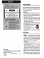
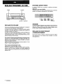
PRECAUTIONS
Read the Operating Instructions carefully and completely before
operating the unit. Be sure to keep the Operating Instructions
for future reference. All warnings and cautions in the Operating
Instructions and on the unit should be strictly followed, as well
as the safety suggestions below.
Installation
1 Water and moisture — Do not use this unit near water, such
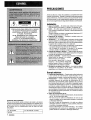
“CAUTION:TO REDUCE THE RISK OF
ELECTRIC SHOCK,
DO NOT REMOVE COVER (OR BACK).
NO USER-SERVICEABLE
PARTS INSIDE.
REFER SERVICING TO QUALIFIED
SERVICE PERSONNEL.”
as near a bathtub, washbowl, swimming pool, or the like.
2 Heat — Do not use this unit near heat sources, including
heating vents, stoves, or other appliances that generate heat.
It also should not be placed in temperatures less than 5°C
(41”F) or higher than 35°C (95”F).
3 Mounting surface — Place the unit on a flat, even surface.
4 Ventilation — The unit should be situated with adequate
space around it so that proper heat ventilation is assured.
Allow 10 cm (4 in.) clearance from the rear and the top of the
unit, and 5 cm (2 in.) from each side.
- Do not place the unit on a bed, rug, or similar surface that
may block the ventilation openings.
- Do not install the unit in a bookcase, cabinet, or airtight
rack where ventilation may be impeded.
5 Objects and liquid entry —Take care that objects or liquids
do not get inside the unit through the ventilation openings.
6 Carts and stands — When placed or
mounted on a stand or cart, the unit
should be moved with care.
Quick stops, excessive force, and
uneven surfaces may cause the unit or
m A~- 3
cart to overturn or fall.
7 Wall or ceiling mounting —The unit should not be mounted
on a wall or ceiling, unless specified in the Operating
Instructions.
Electric Power
1 Power sources — Connect this unit only to power sources
2
3
4
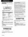
Owner’s record
For your convenience, record the model number and serial
number (you will find them on the rear of your unit) in the space
provided below. Please refer to them when you contact your
Aiwa dealer in case of difficulty.
Model No.
AV-D25
I
ENGLISH
Serial No. (Lot No.)
5
specified in the Operating Instructions, and as marked on
the unit.
Polarization — As a safety feature, some units are equipped
with polarized AC power plugs which can only be inserted
one way into a power outlet. If it is difficult or impossible to
insert the AC power plug into an outlet, turn the plug over
and try again. If it is not still inserted easily into the outlet,
please call a qualified service technician to service or replace
the outlet. To avoid defeating the safety feature of the
polarized plug, do not force it into a power outlet.
AC power cord
- When disconnecting the AC power cord, pull it out by the
AC power plug. Do not pull the cord itself.
- Never handle the AC power plug with wet hands, as this
could result in fire or shock.
- Power cords should be firmly secured to avoid being
severely bent, pinched, or walked upon. Pay particular
attention to the cord from the unit to the power socket.
- Avoid overloading AC power plugs and extension cords
beyond their capacity, as this could result in fire or shock.
Extension cord — To help prevent electric shock, do not
use a polarized AC power plug with an extension cord,
receptacle, or other outlet unless the polarized plug can be
completely inserted to prevent exposure of the blades of the
plug.
When not in use — Unplug the AC power cord from the AC
power outlet if the unit will not be used for several months or
more. When the cord is plugged in, a small amount of current
continues to flow to the unit, even when the power is turned
off.
Outdoor Antenna
1 Power lines — When connecting an outdoor antenna, make
sure it is located away from power lines.
2 Outdoor antenna grounding — Be sure the antenna system
is properly grounded to provide protection against unexpected
voltage surges or static electricity build-up. Article 810 of the
National Electrical Code, ANS1/NFPA70, provides information
on proper grounding of the mast, supporting structure, and
the lead-in wire to the antenna discharge unit, as well as the
size of the grounding unit, connection to grounding terminals,
and requirements for grounding terminals themselves.
TABLE OF CONTENTS
PRECAUTIONS ................................................................... 1
PREPARATIONS
CONNECTIONS .................................................................. 3
BEFORE OPERATION ........................................................6
SOUND
Antenna Grounding According to the National Electrical Code
CUSTOM AUDIO ADJUSTMENT .......................................7
ELECTRONIC GRAPHIC EQUALIZER ..............................8
DSP SURROUND ................................................................ 8
EIASIC OPERATIONS
SELECTION OF AUDIO/VIDEO SOURCE ......................... 9
RECORDING AN AUDIO SOURCE ................................. 10
RAD1O RECEPTION
)
(NEC ART 250 PART H)
NEC-NATIONAL
ELECTRICAL
MANUALTUNING ............................................................. 11
DIRECTTUNING ............................................................... 11
PRESETTING STATIONS .......................m
......................... 12
DOLBY SURROUND
CODE
SELECTING DOLBY PRO LOGIC ...................................13
ADJUSTING SPEAKER LEVEL BALANCE .................... 14
Maintenance
Clean the unit only as recommended
Instructions.
in the Operating
Damaue Reauirinq Service
Have the unit serviced by a qualified service technician if:
- The AC power cord or plug has been damaged
- Foreign objects or liquid have gotten inside the unit
- The unit has been exposed to rain or water
- The unit does not seem to operate normally
- The unit exhibits a marked change in performance
- The unit has been dropped, or the cabinet has been damaged
DO NOT ATTEMPT TO SERVICE THE UNIT YOURSELF.
TIMER
SETTING THE CLOCK ...................................................... 15
SETTING THE SLEEP TIMER .......................................... 15
GENERAL
CARE AND MAINTENANCE ............................................ 16
SPECIFICATIONS ............................................................. 16
TROUBLESHOOTING GUIDE .......................................... 17
PARTS INDEX ................................................................... 18
Check your unit and accessories
AV-D25 Stereo receiver
Remote control
FM antenna
AM antenna
Operating Instructions, etc.
ENGLISH
2
❑
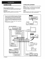
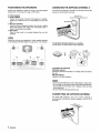
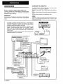
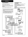
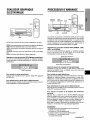
CONNECTIONS
CONNECTING
EQUIPMENT
Jacks and plugs of the connecting cord are color-coded as
follows:
Red jacks and plugs : For the right channel of audio signals
White jacks and plugs: For the left channel of audio signals
Yellow jacks and plugs: For video signals
Before connecting the AC cord
The rated voltage of your unit shown on the rear panel is 120 V
AC. Check that the rated voltage matches your local voltage.
IMPORTANT
Connect the speakers, antennas, and all other external
equipment first. Then connect the AC cord at the end.
Insert the plugs fully into the jacks. Loose connections
produce a humming sound or other noise interference.
*I Be sure to connect the VIDEO OUT terminal of a DVD player
directly to aTV set, not through this unit. Otherwise, the picture
noise may appear when playing the DVDS copy protected.
*2 Input sound through the 5.1 INPUT terminals cannot be
recorded. When recording the sound from the DVD player,
connect the AUDIO OUT (DOWN MIXING) terminals of the
DVD player to the VIDEO l/DVD/MD AUDIO IN terminals of
the unit.
*3When connecting a monaural video, use a sterao-mono
connecting cord (not supplied).
“
- -0
m
0..
~EuUQ
Uma ---
. . . . .
-
Vlllm s
;,q)
Camcorder
:-
VIDE1 IN
L-LWWO IN-R
to VIDEO OUT,
to
AIJDIO
C)t JT
DVD or Video l/MD player*a
-!.
I I I ~’- ”-’
\
11111
I
II
i
fm61m/s’a
L!x
to CENTER
OUT(DVD)
J
.,:--vmeu
.-l
-“
L ur
1111
J==-Jill
JH
LDICable TV*3 1/
Turntable
to VIDEO OUT
I
3
ENGLISH
0
=“”=
Tape deck
,
may
~ and@ in the illustration correspond to the following details.
.—
I
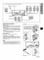
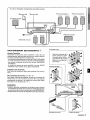
■
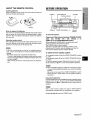
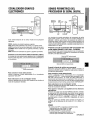
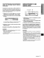
CONNECTING
SPEAKERS
@)
Speaker terminals
Connect front speakers (system A and/or B), a center speaker,
surround speakers andsubwoofer tothecorresponding speaker
terminalson the unit:
- the front speaker cords to the FRONT SPEAKERS terminals
- the center speaker cord to the CENTER SPEAKER terminals
- the surround speaker cords to the SURROUND SPEAKERS
terminals.
- for more powerful bass, the sub woofer (with a built-in amplifier)
cord to the SUPER WOOFER 4 jack
@Center speaker
Front speakers
r
Lift up the terminal flap,
insert the speaker cord lead
into the terminal slot, then
close the flap. Check that the
cord is connected securely.
Surround speakers
Speaker impedance
For all speakers, use speakers of 8 ohms or more.
Connecting + to +, – to - terminals
To get the proper sound effect, the speaker terminals on the unit
and the speaker should be connected with proper polarity; the+
terminal on the unit should be connected to the + terminal on
the speaker (and - to –).
m
Be sure to connect the speaker cords correctly as shown in
the illustration on the right column. Improper connections can
cause shorl circuits in the SPEAKER(S) terminals.
● Do not leave objects generating
magnetism near the speakers.
—-4
●
L
Sub woofer
J
\
Center speaker
J
ENGLISH
4
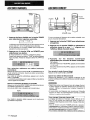
POSITIONING
THE SPEAKERS
Position the speakers to make the most of the Dolby Digital
Surround (5. 1 CH), Dolby Pro Logic or DSP effect.
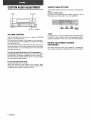
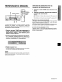
CONNECTING THE SUPPLIED ANTENNAS @
Connect the FM antenna to the FM 75 Q terminals and the AM
antenna to the AM LOOP terminals.
@ Front speakers
@ Center speaker
Position in the center of the two front speakers. In addition,
position on or below the TV set, if connecting a TV set to the
unit.
@ Surround speakers
Place the surround speakers directly to the side of or slightly
behind the listening area. Align them horizontally, about 1
meter (3.2 feet) above ear height.
@ Sub woofer
Place the sub woofer in any place between the two front
speakers.
,
FM antenna
>Y
Sound from the surround speakers or center speaker depends
on the setting of the DSP, Dolby Pro Logic and 5.1 CH function.
To stand the AM loop antenna on a surface
Fix the claw to the slot as shown in the illustration.
To position the antennas
FM feeder antenna:
Extend this antenna horizontally in a T shape and fix its ends to
the wall.
AM loop antenna:
Position for the best reception.
m
●
●
●
Do not bring the FM antenna near metal objects or curtain rails.
Do not bring the AM antenna near other external equipment,
the unit itself, the AC power cord or speaker cords, as noise
will be picked up.
Do not unwind the AM loop antenna wire.
CONNECTING
AN OUTDOOR ANTENNA
For better FM reception,
use of an outdoor antenna is
recommended. Connect the outdoor antenna to the FM 75 Q
terminals.
5
ENGLISH
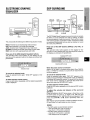
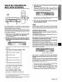
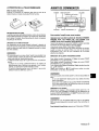
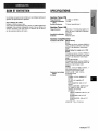
ABOUTTHEREMOTE
CONTROL
BEFORE OPERATION
Inserting batteries
Detach the battery cover on the rear of the remote control and
insert two R6 (size AA) batteries.
POWER
II
TAPE MONITOR
Function indicators
VOLUME
I
R6<AA)
PHONES
When to replace the batteries
The maximum operational distance between the remote control
and the sensor on the unit should be approximately 5 meters
(16 feet). When this distance decreases, replace the batteries
with new ones.
Using the remote control
The instructions in this manual refer mainly to the buttons on the
main unit. Buttons on the remote control with the same names
as those on the main unit can be used as well.
m
●
●
If the unit is not going to be used for an extended period of
time, remove the batteries to prevent possible electrolyte
leakage.
The remote control may not operate correctly when:
- The line of sight between the remote control and the remote
sensor in the display window is exposed to intense light, such
as direct sunlight.
- Other remote controls are used nearby (those of television,
etc.)
FRONT SPEAKERS A, B
Function
buttons
To turn the unit on
Press one of the function buttons (TUNER, PHONO,
AUX,
CD, VIDEO
1/5.1
CH, VIDEO
2 or
VIDEO 3) or theTAPE MONITOR button.
When pressing the TUNER button, the previously tuned
station is received (Direct Play Function).
The POWER button is also available.
Operation is possible after four seconds, while the VOL
(volume) level or function name is displayed one after the
other and the selected function indicator flashes.
To select the front speaker system
To use speaker system A: Set the FRONT SPEAKERS A button
to sON.
To use speaker system B: Set the FRONT SPEAKERS B button
to sON.
To use both speaker systems: Set both the buttons to s ON.
Set the button(s) to .EOFF to turn off the speaker system(s).
m
As the front speaker systems A and B are connected in series:
- The sound will be slightly decreased when using both speaker
systems
- No sound can be heard if the FRONT SPEAKERS A and B
buttons are set to ~ ON when only one speaker system is
connected
Using the headphones
Connect headphones to the PHONES jack with a standard stereo
plug (06.3 mm, 1/4 inch). Be sure to set the FRONT SPEAKERS
A and B buttons to 10FF. Otherwise sound is output from the
speakers.
The 5.1 CH function, Dolby Pro Logic or DSP system is
automatically canceled when the headphones are plugged in.
To turn the unit off, press the POWER button.
ENGLISH
6
CUSTOM AUDIO ADJUSTMENT
SUPER T-BASS SYSTEM
The T-BASS system enhances the realism of low-frequency
sound.
Press the T-BASS button.
Each time it is pressed, the level changes. Select one of the
three levels, or the off position to suit your preference.
I
. .
K
—
1—
MUTING
‘1
::
I
Turn the VOLUME control on the unit, or press the VOLUME
buttons on the remote control.
The volume level is shown on the display for four seconds. It
can be adjusted between Oand MAX (31). It flashes when being
set over the level 21.
The volume level remains memorized even after the power is
turned off. However, if the power is turned off when the volume
is set to more than 17, it is automatically set to 16 the next time
the power is turned on.
To adjust the Ieft/right balance of the front speakers
Press the BALANCE button to display ‘l_/R OdB. Then press
the DOWNY or UPA button repeatedly within four seconds.
Note that the front speakers balance of the 5.1 CH and Dolby
Pro Logic modes is also changed.
To mute the sound temporarily
Press the MUTING button (-20 dB).
“MUTE ON” appears on the display for four seconds. While
muting the sound, the selected function indicator flashes. Press
the MUTING button again to restore the sound.
ENGLISH
. . . . . .
. . . . . .
. . . . . .
&+&&+E+(cancel)
BALANCE
VOLUME CONTROL
7
. . . .
. . . .
. . . .
Low-frequency sound may be distorted when the T-BASS system
is used for a disc or tape in which low-frequency sound is
originally emphasized. In this case, cancel the T-BASS system.
SOUND ADJUSTMENT
RECORDING
DURING
The output volume and tone of the speakers or headphones
may be freely varied without affecting the level of the recording.
ELECTRONIC
EQUALIZER
GRAPHIC
DSP SURROUND
n
.Z=
\
C3QC2
cac2Qc2
(J
,
C2ua’
GEQ
MANUAL
SELECT
UP>,
DOWN<
DSP
GiQ
This unit provides the following five different equalization modes.
ROCK: Powerful sound emphasizing treble and bass
POP: More presence in the vocals and midrange
JAZZ: Accented lower frequencies for jazz-type music
CLASSIC: Enriched sound with heavy bass and fine treble
BGM: Calm tone with suppressed bass and treble
DOWNY
The DSP (Digital Signal Processor) surround circuits can recreate
the effect of sounds reflected from walls or ceilings, to obtain
the sound presence of real environments. There are four modes
with matching graphic equalization modes. Equalization modes
are selected automatically and can also be selected or turned
off to suit your preference.
Press one of the DSP buttons (DANCE, LIVE, HALL or
ARENA).
The selected mode name appears on the display for four
seconds, and the selected DSP and matching GEt2 modes on
the display are enclosed with parentheses.
Press one of the GEQ (Graphic Equalizer) buttons.
The selected mode name appears on the display for four
seconds, and the selected mode on the display is enclosed with
parentheses.
Selected DSP mode
Matching GEQ mode
Selected mode
To cancel the selected mode
Press the selected button again. “GEQ OFF appears on the
display.
To select with the remote control
Press the GEQ button repeatedly until the desired equalization
mode is displayed.
When the music source is monaural
Select LIVE to obtain a simulated stereo effect. When DANCE,
HALL or ARENA is selected, no sound will be heard from the
surround speakers.
To cancel the selected mode
Press the selected button again. “DSP OFF appears on the
display. Even if canceling the selected DSP mode, the matching
or selected GEQ mode still remains. To cancel both the selected
DSP mode and the matching (or selected) GEQ mode at the
same time, press the DSP/GEQ OFF button.
To select with the remote control
Press the DSP button repeatedly until the desired DSP mode is
displayed.
To adjust the volume and balance of the surround
speakers
Press the MANUAL SELECT button twice or three times, while
the DSP system is turned on, to display “S-R OdB (for right
surround speaker) or “S-L OdB (for left surround speaker). Then
UPA button repeatedly within four
press the DOWNVor
seconds.
Note that the surround speakers volume and balance of the 5.1
CH and Dolby Pro Logic modes are also changed.
●
●
The DSP system is automatically canceled:
- when the Dolby Pro Logic is turned on
- when the 5.1 CH function is selected
The DSP system cannot be turned on:
- while the 5.1 CH function is selected
- while headphones are plugged in
ENGLISH
8
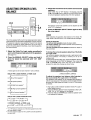
SELECTION
SOURCE
To change a displayed name for the VIDEO 1/5.1 CH
button and VIDEO 2 button
When the VIDEO 1/5.1 CH button is pressed, VIDEO 1 is
displayed initially. It can be changed to DVD or MD.
With the power on, press the POWER button while pressing the
VIDEO 1/5.1 CH button.
This VIDEO 1/5.1 CH button also works as the 5.1 CH (5.1
INPUT) function switch. While the selected function name
(VIDEO 1, DVD or MD) for the VIDEO 1/5.1 CH button is
displayed, press the button again. The function name will change
to “5.1 CH” and the source connected to the 5.1 INPUT terminals
is selected.
To resume, press the button again so that the selected function
name is displayed.
OF AUDIO/VIDEO
1
The displayed name for VIDEO 2 button can be changed to
VIDEO 2, LD orTV with the power on, press the POWER button
while pressing the VIDEO 2 button.
1 Select the program source.
Press one of the function buttons or the TAPE MONITOR
button.
To adjust the sound level of the connected source
The input sensitivity level of each function (except the TUNER
and 5.1 CH functions) can be adjusted.
When the sound level of the connected source is higher or lower
than that of the TUNER, adjust it as follows.
1 Select the function to be adjusted.
Press the function button accordingly and play the source.
Television, etc.
I AUX
Com~act disc
I CD
Video
VIDEO 1/5.1 CH, VIDEO 2,
VIDEO 3
LD or Cable TV
VIDEO 2
MD or DVD
VIDEO 1/5.1 CH
2 Press the UPA or DOWNV
I
The function buttons to be pressed (except PHONO) depend
on the equipment connected to the input terminals on the
rear panel of the unit.
When using a turntable with a built-in equalizer amplifier, set the
switch of the equalizer amplifier to off. See the instructions of
the turntable for further information.
2 Start the selected
program source.
3 Adjust the sound.
About the video source to the monitor or TV
Selected VIDEO source
Vl: VIDEO 1, V2: VIDEO 2, V3: VIDEO 3
The selected video source is indicated on the display and the
video signal through the MONITOR VIDEO OUT jack is output
on the TV.
9
ENGLISH
button repeatedly.
The level can be adjusted between -6dB (MIN) and +f3dB (MAX)
in 2dB steps. Adjust the level so that the sound is output at the
same level as the TUNER.
●
●
The input sensitivity level of the TUNER or 5.1 CH function
cannot be adjusted.
That of the TAPE MONITOR cannot be adjusted either.
Even if the TAPE MONITOR is selected and the TAPE
MONITOR indicator turns red, pressing the UPA or DOWNV
button will change the level of the function displayed on the
window.
TO PLAY A DVD RECORDED
DIGITAL SURROUND
IN DOLBY
RECORDING
This receiver has the 5.1 INPUT connectors supporting Dolby
Digital decoder with the 5.1 ch output terminals. When a DVD
player that contains a Dolby Digital decoder is connected to the
receiver, you can enjoy theater-quality audio right in your home
when playing discs recorded in Dolby Digital Surround.
AN AUDIO SOURCE
TAPE MONITOR
1
1 Press the VIDEO 1/5.1 CH button to select the
VIDEO 1 (DVD or MD) function.
2 Press the VIDEO 1/5.1 CH button again.
1 Select the program source to be recorded.
Press one of the function buttons.
“5.1 CH” appears on the display and the DVD player
connected to the 5.1 INPUT terminals is selected as a source.
2 Set the tape deck or MD recorder to the recording
mode.
3 Start the selected
3 Start playing the DVD recorded
Surround.
in Dolby Digital
To resume the VIDEO 1, DVD (2 ch stereo) or MD function, press
the VIDEO 1/5.1 CH button again.
m
The 5.1 CH function is automatically canceled and the VIDEO
1, DVD or MD function is selected:
- when the Dolby Pro Logic is turned on
- when headphones are plugged in
● The 5.1 CH function cannot be selected while headphones
are
plugged in.
●
program source.
To monitor recorded sound during recording (when the
connected tape deck is a three-head system)
Press the TAPE MONITOR button. “TAPE ON” appears on the
display for four seconds, and then the source name selected in
step 1 comes back on. To cancel the tape monitor, press it again
so that “TAPE OFF appears.
m
●
●
●
●
Any sound control system has no effect on recording (see page
7).
Input sound through the 5.1 INPUT terminals cannot be
recorded. When recording the sound from the DVD player,
connect the AUDIO OUT (DOWN MIXING) terminals of the DVD
player to the VIDEO l/DVD/MD AUDIO IN terminals of the unit.
When recording sources by the MD recorder connected to the
VIDEO l/DVD/MD AUDIO OUT terminals, select the source
after pressing the VIDEO 2 or VIDEO 3 button (V2 or V3 should
be displayed).
Recording cannot be done while the VI indication is displayed
on the window.
Input sound from the tape deck connected to the TAPE
MONITOR IN terminals cannot be recorded.
ENGLISH 10
❑
DIRECT TUNING
MANUAL TUNING
TUNER
Numbered
buttons
2
1
DOWN7,
1 Press the TUNER button repeatedly
desired band.
to select the
~FM--+AM~
or DOWNY
When you know the frequency of the desired station, you can
tune in directly to the station.
1 Press the TUNER button to select a band.
The display changes to frequency indications after indicating
band and video source (V1, V2 or V3) for two seconds.
When the TUNER button is pressed while the power is off,
the power is turned on directly.
2 Press the UPA
station.
UPA
2 Press the TUNER button and hold it down until
(’
.....“flashes on the display (Direct Tuning Mode).
button to select a
Each time the button is pressed, the frequency changes,
When a station is received, “TUNE” is displayed for two
seconds. During FM stereo reception, (I(O)]) is displayed.
3 Press the appropriate numbered
in to the desired station.
buttons to tune
Example:
To tune in to 106.50 MHz, press 1, 0, 6, 5 and O buttons.
To tune in to 95.20 MHz, press 9, 5, 2 and Q buttons,
To search for a station quickly (Auto Search)
Keep the UPA or DOWNY button pressed until the tuner starts
searching for a station. After tuning in to a station, the search
stops.
To stop the Auto Search manually, press the UPA or DOWNV
button.
● The
Auto Search may not stop at stations with very weak
signals.
When an FM stereo broadcast contains noise
Press the MONO TUNER button on the remote control so that
“MONO appears on the display.
Noise is reduced, although reception is monaural.
To restore stereo reception, press the button so that “MONO
disappears.
I 1 ENGLISH
To cancel the Direct tuning mode
Press the UPA or DOWNT button.
When using the remote control
Carry out steps 1 and 2 above, and press the numbered buttons
on the remote control to tune in to the desired station.
m
●
●
When entering a frequency out of tuning range, the value
flashes for two seconds and then goes off. Check the frequency
and repeat step 3 correctly.
When entering a frequency not covered by the tuning interval,
the value is automatically rounded up or down to the closest
one covered by it.
To change the AM tuning interval
The default setting of the AM tuning interval is 10 kHz/step. If
you use this unit in an area where the frequency allocation
system is 9 kHz/step, change the tuning interval.
Hold down the TUNER button and press the POWER button
immediately. Note that the unit is set to the Direct Tuning mode
if the TUNER button is pressed and held down for about half
a second.
To reset the interval, repeat this procedure.
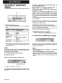
PRESETTING
STATIONS
PRESET NUMBERTUNING
1 Press the TUNER button to select a band.
Numbered
buttons
TUNER
BAND
2 Press the numbered
number.
buttons to select a preset
Example:
To select preset number 25, press 2 and 5.
To select preset number 7, press O and 7.
To clear a preset station
Select the preset number of the station to be cleared .Then, press
the SET button, and press the SET button again within four
seconds.
The preset numbers of all other stations in the band with higher
numbers are decreased by one.
The unit can store a total of 32 preset stations. When a station is
stored, a preset number is assigned to the station. Use the preset
number to tune in to a preset station directly.
When using the remote control
Press the TUNER BAND button to select a band, then press the
numbered buttons to select a preset number.
1 Press the TUNER button to select the band, and
press the UPA or DOWNY button to select a
station. Direct tuning is also available.
2 Press the SET button to store the station.
A preset number assigned to the station, beginning from 1 in
consecutive order for each band, flashes in the display for
two seconds.
3 Repeat steps 1 and 2.
No ‘more stations will be stored if a total of 32 stations have
already been stored for all the bands.
m
When the AM tuning interval is changed, all preset stations are
cleared. The preset stations have to be set again.
ENGLISH
12
This unit is equipped with the Dolby Pro Logic decoder and also
supports the Dolby Digital decoder with the 5.1 ch output
terminals.
The unit and the center and surround speakers (standard) assure
full-scale home theater sound. When playing back discs or video
software that have been recorded in Dolby Pro Logic or Dolby
Digital Surround, astonishingly realistic sound surrounds the
listener to create a new level of audio/visual entertainment.
Independent control of the five channels allows the listener to
enjoy the same type of sound reproduction experienced in movie
theaters. Voices are reproduced in the front and center sound
field, while ambient sounds like cars and crowds are reproduced
on all sides of the listener for an incredibly lifelike audio/video
experience. Please read the following carefully to “tune” the
system’s output to match the characteristics of your listening
space.
TO SELECT A DOLBY PRO LOGIC MODE
1,?
1 Press the DOLBY SURROUND button repeatedly
to select the appropriate mode.
When selecting the DOLBY PRO LOGIC or 3 STEREO mode,
the indicator lights up, and the selected mode name runs
through on the display. Each time the button is pressed, the
mode changes as shown below.
Check the following:
Before enjoying the DOLBY SURROUND sound, adjust the
proper balance of the speaker sound levels (see page 14).
● Make sure the speakers are properly connected and positioned
(see pages 3,4 and 5).
● Make sure the TV set and video
unit are properly connected
●
●
(see page 3).
“
Make sure the disc and video
tape,
etc., support
Dolby
Pro
Logic or Dolby Digital Surround.
SELECTING
r
DOLBY PRO LOGIC
The optimal Dolby Pro Logic mode depends on the type and
placement of the speakers. It is recommended that the optional
Aiwa speakers should be used for all channels, for example, the
SX-R1 200 for surround speakers, the SX-C1 200 for a center
speaker and the SX-AV1 200 for front speakers. Check your
current type and placement of the speakers and select the
recommended Dolby Pro Logic mode accordingly.
The recommended
mode
Surround speaker
(Rear speaker)
No surround
speaker
Smaller-size
3 STEREOWIDE
3 STEREONORMAL
No speaker
When selecting the DOLBY PRO LOGIC mode in step 1:
“NORMAL!’, “WIDE and “PHANTOM” appear in turn.
When selecting the 3 STEREO mode in step 1:
“NORMAL’ and “WIDE” appear one after the other.
m
PHANTOM mode: Select this mode when the center speaker is
not connected. All center channel signals are redistributed to
the left and right channel speakers.
3 STEREO mode: Select this mode when the surround speakers
are not connected.
13
ENGLISH
●
PHANTOM
—
DOLBY PRO LOGIC OFF(cancel) J
button again and
hold it down until the center speaker mode to be
selected appears.
●
DOLBY PRO
DOLBY PRO
LOGIC-NORMAL
LOGIC-WIDE
3 STEREO
2 Press the DOLBY SURROUND
Center speaker
Larger-size
DOLBY PRO LOGIC~
●
●
Depending on the sound source or listening condition, surround
effect may not be obtained even when the Dolby Pro Logic is
set to on.
The full Dolby Pro Logic effect cannot be obtained when using
the software without IIEIIDDIBVSU-WWJI
mark. In this case, use
the DSP surround system instead (see page 8).
The Dolby Pro Logic system is automatically canceled:
- when the DSP system is turned on
- when the 5.1 CH function is selected
- when headphones are plugged in
The Dolby Pro Logic cannot be set to on while headphones
are plugged in.
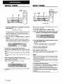
ADJUSTING
BALANCE
SPEAKER LEVEL
3 Adjust the sound level of the center and surround
speakers.
While “CEN”, “S-L’ or “S-R” flashes in the display, press the
UPA or DOWNY button so that the sound level of the center
or surround speakers matches that of the front speakers.
1
2,4
3
4 Press the MANUAL SELECT button again to stop
the noise signal.
m
3
1
The balance of the front speakers can be adjusted as well
while “UR is displayed.
When adjusting the speakers level balance of the Dolby Pro
Logic, those of the DSP and 5.1 CH modes are also changed.
The unit is equipped with a built-in test signal generator called a
noise sequencer for easy balance adjustment of all five channels.
The sequencer outputs a noise signal that “travels” from channel
to channel, enabling the simple adjustment of sound level to
achieve the same apparent loudness, at your listening position,
from each channel.
1 Select the Dolby Pro Logic mode according to
your current type and placement of the speakers.
(See page 13.)
2 Press the MANUAL SELECT button and hold it
down for about two seconds until “L/R OdB”
appears.
About the channels
The left and right speakers create the stereo effect.
The center speaker helps achieve precise sound positioning
over a broad sound field.
The rear-mounted surround speakers enhance the “depth” of
the sound field.
To change the surround speakers delay time of the Dolby
Pro Logic mode
The surround speakers reproduce sounds a split second after
the front speakers. The delay is initially
set to 20 ms
(milliseconds).
To change this standard delay time, press the MANUAL SELECT
button repeatedly so that “SUR” is displayed. Then, press the
UPA or DOWN~ button. Each time one of the buttons is
pressed, the delay time changes as shown below.
A noise signal is sent to each channel in turn as follows:
DOLBY PRO LOGIC NORMAL
or WIDE mode
+15ms-20’ms
4+30ms
+
To adjust the speakers level balance while listening to
the source (Dolby Pro Logic and 5.1 CH modes)
The speakers level balance can be changed after adjusting it
with the noise sequencer. The balance can be changed whenever
the Dolby Pro Logic system is turned on or the 5.1 CH function
is selected.
+
IJR OdB (Left front speakerT1
+
CEN OdB (Center speaker)
4
UR OdB (Right front speaker)*l
1 Play a disc or video software recorded in Dolby Pro Logic or
+
Dolby Digital Surround.
2 Press the MANUAL SELECT button repeatedly so that ‘W!”,
“CEN”, “S-P’ or “S-R appears on the display.
3 Press the UPA or DOWNV button while the speaker name
to be adjusted is displayed.
S-R OdB (Right surround speaker)”z
4
S-L ?dB (Left surround speaker)* 2
DOLBY PRO LOGIC PHANTOM
r
UR OdB*l +
UR OdB*l
S-L 0dB*2~
S-R 0dB*2 d
3 STEREO
~
mode
NORMAL or WIDE mode
UR OdB*’+
CEN OdB +
UR 0dB*17
‘1 “L” or “R flashes to indicate one of the front speakers from which
the noise signal is output.
*2 The noise signal is output from the L and R surround speakers at
the same time.
ENGLISH
14
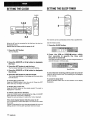
SETTING THE SLEEP TIMER
SETTING THE CLOCK
CLOCK
1
1,3,5
2
2,4
The receiver can be automatically turned off at a specified time.
When the AC cord is connected for the first time, the clock on
the display flashes.
Set the time aa follows while the power is off.
Use the remote control.
1 Press the SLEEP button.
1 Press the SET button.
The hour flashes.
2 Press
the UPF or DOWN<
button
within
four
seconds
to specify
the time
until
the power is turned off.
Each time the button is pressed, the time changes between 5
and 240 minutes in 5-minute steps.
2 Press the DOWN7
the hour.
or UPA
button to designate
3 Press the SET button to set the hour.
The hour stops flashing and the minute starts flashing,
Specified time
4 Press the DOWNY
the minute.
or UPA
button to designate
5 Press the SET button to set the minute.
The minute stops flashing on the display and the clock starts
from 00 second.
To correct the current time
Press the POWER button to turn the unit off. Press the SET
button and carry out steps
1 to 5 above.
To display the current time
Press the CLOCK button on the remote control. The clock is
displayed for 4 seconds.
To switch to the 24-hour standard
Press the POWER button while pressing the UPA or DOWNY
button while the current time is displayed.
Repeat the same procedure to restore the 12-hour standard.
If the clock display flashes while the power is off
by a power interruption.
The current time needs
to be reset.
If power is interrupted for more than approximately 24 hours, all
settings stored in memory after purchase need to be reset.
This is caused
15
ENGLISH
To check the time remaining until the power is turned off
Press the SLEEP button once. The remaining time is displayed
for four seconds.
To cancel the sleep timer
Press the SLEEP button twice so that “SLEEP
disappears.
on the display
CARE AND MAINTENANCE
Occasional care and maintenance of the unit is needed to
optimize the performance of your unit.
To clean the cabinet
Use a soft dry cloth.
If the surfaces are extremely dirty, use a soft cloth lightly
moistened with mild detergent solution. Do not use strong
solvents, such as alcohol, benzine or thinner as these could
damage the finish of the unit.
SPECIFICATIONS
FM tuner section
Tuning range
Usable sensitivity
(IHF)
Antenna terminals
87.5 MHz to 108 MHz
13.2 dBf
75 ohms (unbalanced)
AM tuner section
Tuning range
530 kHz to 1710 kHz (10 kHz step),
531 kHz to 1602 kHz (9 kHz step)
350 pV/m
Loop antenna
Usable sensitivity
Antenna
Amplifier section
Power output
Total harmonic
distortion
Inputs
[Stereo Mode]
Front
65 watts per channel, Min. RMS at 8
ohms, from 40 Hz to 20 kHz, with no
more than 0.97. Total Harmonic
Distortion
[Dolby Pro Logic or 5.1 CH Mode]
Front
50 watts per channel, Min. RMS at 8
ohms, from 40 Hz to 20 kHz, with no
more than 0.9% Total Harmonic
Distortion
Rear (Surround)
25 watts per channel, Min. RMS at 8
ohms, 1 kHz, with no more than 0.9°L
Total Harmonic Distortion
Center
50 watts, Min. RMS at 8 ohms, 1 kHz,
with no more than 0.97. Total
Harmonic Distortion
0.08 % (40 W, 1 kHz, 8 ohms, Front)
AUDIO IN
PHONO: 2.5 mV, adjustable (47
kohms)
CD: 200 mV, adjustable (47
kohms)
TAPE MONITOR: 300 mV (47
kohms)
VIDEO l/DVD/MD, VIDEO 2/LD/
TV, VIDEO 3, AUX: 200 mV,
adjustable (47 kohms)
5.1 INPUT
FRONT, CENTER: 450 mV (47
kohms)
SURROUND: 300 mV (47
kohms)
SUB-WOOFER: 400 mV (47
kohms)
VIDEO IN: 1 Vp-p (75 ohms)
ENGLISH t
6
outputs
Muting
AUDIO OUT (REC OUT): 200 mV (1
kohm)
VIDEO OUT (MONITOR): 1 Vp-p (75
ohms)
SUPER WOOFER: 1.2 V
FRONT SPEAKERS IMP: 8Q
(front speakers A and B): accepts
speakers of 8 ohms or more.
SURROUND SPEAKERS IMP: 8f2
(surround speakers): accepts
speakers of 8 ohms or more
CENTER SPEAKER IMP: 8Q: accepts
a speaker of 8 ohms or more.
PHONES (stereo jack): accepts
headphones of 32 ohms or more
–20 dB
General
Power requirements
Power consumption
Dimensions
(W XHXD)
Weight
120 V AC, 60 Hz
135W
430 x 155x 351 mm
(17 x 61/8 X 137/8 in.)
9.4 kg (20 lb 12 OZ.)
Specifications and external appearance are subject to change
without notice.
DOLBY PRO LOGIC
Manufactured under license from Dolby Laboratories Licensing
Corporation.
“DOLBY” the double-D symbol 00 and “PRO LOGIC” are
trademarks of Dolby Laboratories Licensing Corporation.
TROUBLESHOOTING
GUIDE
If the unit fails to perform as described
Instructions, check the following guide.
in these Operating
GENERAL
There is no sound.
● Is the AC cord connected
properly?
● Is there an incorrect connection?
(+ page 3)
● There may be a short circuit in the speaker terminals.
+ Disconnect
the AC cord, then correct the speaker
connections.
● Was an incorrect fu netion button pressed?
● Are the
FRONT SPEAKERS A and B buttons set correctly?
(+ page 6)
Sound is emitted from one speaker only.
● Is the BALANCE
set appropriately?
● Is the other speaker disconnected?
Sound is heard at a very low volume.
● Has the MUTING button been pressed?
An erroneous display or a malfunction occurs.
~ Reset the unit as stated below.
TUNER SECTION
There is constant, wave-like static.
● Is the antenna
connected properly? (+ page 5)
● Is the FM signal weak?
+ Connect an outdoor antenna.
The reception contains noise interference or the sound is
distorted.
. Is the system picking up external noise or multipath distortion?
+ Change the orientation of the antenna.
+ Move the unit away from other electrical appliances.
To reset
If an unusual condition in the display window or malfunction
occurs, reset the unit as follows.
1 Press the POWER button to turn off the power.
2 Press the POWER button while pressing the SET button.
Everything stored in memory after purchase is canceled.
If the power cannot be turned off in step 1 because of a
malfunction, reset by disconnecting the AC cord and carry out
step 2.
17
ENGLISH
PARTS INDEX
Instructions about each part on the unit or remote control are
indicated on the pages listed below.
~a;~habetical
order)
AUX
BALANCE
CD
CLOCK
DOLBY SURROUND
DOWN V (<)
DSP
FRONT SPEAKERS A, B
GEQ
MANUAL SELECT (TEST)
MONO TUNER
MUTING, MUTE
PHONES
PHONO
POWER
SET
SLEEP
TAPE MONITOR
T-BASS
TUNER (TUNER BAND)
UP A (P)
VIDEO 1/5.1 CH
VIDEO 2
VIDEO 3
VOLUME (V,
A)
Pages
6, 9
7
6, 9
15
13, 14
8,11,12,14,15
8
6
8
8, 14
11
7
6
6, 9
6,11,15
12, 15
15
6,9,10
7
6,9,11,12
8,11,12,14,15
6,9,10
6, 9
6,9
7
ENGLISH18
PRECAUCIONES
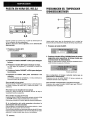
Antes de utilizar la unidad, lea cuidadosa y completamente este
manual instrucciones. Guarde el manual de instrucciones para
futuras referencias. Todos Ios avisos y precauciones del manual
de instrucciones y de la unidad deberan seguirse estrictamente,
asi como Ias sugerencias de seguridad indicadas a continuaci6n.
‘/
/
\
IRISKOFELECTRIGSHOCKI/
,6,
I
\
DO NOT OPEN
ION:PARA REDUCIR EL RIESGO
DE QUE SE PRODUZCAN SACUDIDAS
ELECTRICAS, NO QUITE LA CUBIERTA
(O PANEL POSTERIOR).
EN EL INTERIOR NO HAY PIEZAS QUE
DEBA REPARAR EL USUARIO.
SOLICITE LAS REPARACIONES AL
PERSONAL DE SERVICIO CAPACITADO.”
qf:$,~
. ..
1~:$
,’%
* ,,=.,~
g-y
Instalacion
1 Agua y humedad — No utilice esta unidad cerca del agua,
como al Iado de una bafiera, un Iavabo, una piscina, etc.
2 Calor — No utilice esta unidad cerca de fuentes termicas,
;/g/(
como salidas de calefaccion, estufas, ni demas aparatos que
:.=r
....
$“,,:;3$7
,;r=j-”.ir
generen calor.
fyf$~j
it‘yf,*
Tampoco debera someterse a temperatures inferiors a 5°C
“-w.
r>l~,:=.
>$.m
j ,3”p,%j
(41 “F) ni superiors a 35°C (95°F).
$:,$jyf
J~&!!.
3 Superficie de montaje — Coioque la unidad sobre una
:1+1*%,3Y
,s&
,,~.
superficie plana y nivelada.
@1,
~-=
:
4 Ventilation
— La unidad debera colocarse donde tenga
$#$
espacio suficiente a su airededor para asegurar su ventilation
adecuada. Deje un espacio Iibre de 10 cm en la parte posterior
y superior de la unidad, y de 5 cm a cada Iado.
- No la coloque sobre una cama, una alfombra, ni nada similar
que pueda bloquear Ias aberturas de ventilaci6n.
- No la instaie en una Iibreria, un armario, ni un bastidor
cerrado, donde la ventilation podria ser deficient.
5 Entrada de objetos y Iiquidos — Tenga cuidado de que en
el interior de la unidad no entren objetos pequefios ni Iiquidos
a traves de [as aberturas de ventilation.
6 Carritos y estantes — Cuando haya colocado o montado la
unidad sobre un estante o un carrito,
debera moverla con cuidado.
Las paradas repentinas,
la fuerza
excesiva, o Ias superficies desiguales
3
podrian causar el vuelco o la caida de la
@!!!lA&combinacion de la unidad y el carrito.
7 Montaje en una pared o en el techo — La unidad no debera
montarse en una pared ni en el techo, a menos que se
especifique en el manual de instrucciones.
Eneraia electrica
~
1 Fuentes de alimentacion — Conecte esta unidad solamente
Anotacion del propietario
Para su conveniencia, anote el ntimero de modelo y el numero
de serie (Ios encontrara en el panel trasero de su aparato) en el
espacio suministrado mas abajo. Mencionelos cuando se ponga
en contacto con su concesionario
Aiwa en caso de tener
dificultades.
N.” de modelo
AV-D25
I
ESPAfiOL
N.” de serie (N.” de Iote)
a Ias fuentes de alimentacion
especificadas
en Ias
instrucciones de manejo, y como esta marcado en la unidad.
2 Polarization
— Como medida de seguridad, algunas
unidades disponen de enchufes de alimentacion de CA
polarizados que solamente podran insertarse de una forma
en el tomacorriente de la red. Si es dificil o imposible insertar
el enchufe de alimentacion de CA en un tomacorriente de la
red, dele la vuelta e intentelo de nuevo. Si sigue sin poder
insertarse bien, Ilame a un tecnico de servicio cualificado para
que reemplace el tomacorriente, para evitar anular la funcion
de seguridad del enchufe polarizado, no 10inserte a la fuerza
en un tomacorriente.
3 Cable de alimentacion de CA
- Para desconectar el cable de alimentacion, tire del enchufe
de CA. No tire del propio cable.
- No tome nunca el cable de alimentacion de CA con Ias
manes htimedas, ya que esto podria resultar en incendios
o descargas electrical.
- No pise el cable de alimentacion ni 10 pine con objetos
colocados encima o contra el, ya que podrian producirse
incendios o descargas electrical.
- Evite sobrecargar
Ios tomacorrientes
y Ios cables
prolongadores por encima de su capacidad, ya que esto
podria resultar en incendios o descargas electrical.
Cable prolongador — Para evitar descargas electrical, no
utilice el enchufe de alimentacion de CA polarizado con un
cable prolongador ni tomacorriente a menos que el enchufe
pueda insertarse completamente a fin de evitar que sus
cuchillas queden al descubierto.
5 Periodos sin utilization — Cuando no vaya a utilizar la
unidad durante varies meses, desenchufe et cable de
alimentacion de CA del tomacorriente de la red. Cuando el
cable de alimentacion
estas enchufado, circulara una
pequeha corriente
por la unidad, incluso aunque la
alimentacion este desconectada.
4
Antena exterior
INDICE
PRECAUCIONES ................................................................ 1
PREPARATIVES
coNExloNEs
.....................................................................3
ANTES DE LA OPERACION .............................................. 6
SONIDO
1 Lheas electrical — Cuando conecte una antena exterior,
cerciorese de que este alejada de Ias Iineas electrical.
2 Puesta a tierra de la antena exterior — Cerciorese de aue
el sistema de antena este adecuadamente puesto a tiewa
como medida de protection
contra sobretensiones
inesperadas o la generation de electrostatic.
El articulo
810 del codigo National Electric Code, ANS1/NFPA70
proporciona information sobre la puesta a tierra adecuada
del mastil, la estructura de soporte, y la acometida a la unidad
de descarga de la entena, asi como sobre el tamafio de la
unidad de puesta a tierra, la conexion de Ios terminals de
puesta a tierra, y Ios requisites de puesta a tierra de Ios
propios terminals.
Puesta
a tierra
de la antena
segun
el Codigo
Electrico
National
AJUSTE DEL SONIDO A SU GUSTO ................................ 7
ECUALIZADOR GRAFICO ELECTRONIC . ..................... 8
SONIDO PERIMETRICO DEL PROCESADOR DE
SENAL DIGITAL ............................................................. 8
OPERAClONES
BASICAS
SELECCION DE UNA FUENTE DE AUDIO/VIDEO ..........9
GRABACION DE UNA FUENTE DE AUDIO .................... 10
ESCUCHA
DE LA RADIO
SINTONIA MANUAL ......................................................... 11
SINTONIA DIRECTA ......................................................... 11
MEMORIZATION DE EMISORAS .................................... 12
DOLBY SURROUND
SELECCION DE DOLBY PRO LOGIC ............................. 13
AJUSTE DEL EQUILIBRIA DEL NIVEL
14
ENTRE ALTAVOCES
. . . . . . . . . . . . . . . . . . . . . . . . . . . . . . . . . . . . . . . . ..m
.. . . . . .. .
TEMPORIZADOR
(NEC,ARTICULO
NEC(CODIGO
ELECTRICO
250, PARTE H)
PUESTA EN HORA DEL RELOJ ..................................... 15
PROGRAMACION DEL TEMPORIZADOR
CRONODESCONECTADOR ........................................ 15 [
NACIONAL)
GENERALIDADES
Mantenimiento
Limpie la unidad solamente como se recomienda en ei
de instrucciones.
Dafios aue reauieren
manuai
renaracion
CUIDADOSY MANTENIMIENTO ..................................... 16
EsPEclFlcAcloNEs
........................................................l6
GUIA PARA LA SOLUCION DE PROBLEMAS ..............17
INDICE DE LAS PARTES ................................................. 18
Haga que la unidad sea revisada por un tecnico de servicio
cualificado si:
- se ha dariado el cable de alimentacion o el enchufe de CA.
- en ei interior de la unidad han entrado objetos o Iiquidos.
- la unidad ha estado expuesta a la Iluvia o al agua.
- la unidad parece no funcionar normalmente.
- la unidad rxesenta un cambio notable en su rendimiento.
- la unidad ha caido, o se ha daiiado su caja.
NO INTENTE REPARAR USTED MISMO LA UNIDAD.
Compruebe
su unidad y accesorios
Receptor estereo AV-D25
Antena de FM
Controlador remoto
s.
::
,:
$:
.“.
‘Jr;
:‘fk
!;?,;:.
w
Antena de AM
Manual de instrucciones, etc.
ESPANOL
2
CONEXIONES
CONEXION
DE EQUIPOS
Las clavijas de Ios cables conectores y Ias tomas estan
codificadas en color de la forma siguiente:
Clavijas y tomas rojas: Para el canal derecho de sefiales de
audio
Clavijas y tomas blancas: Para el canal izquierdo de sefiales de
audio
Clavijas y tomas amarillas: Para sefiales de video
Antes de conectar el cable de alimentacion de CA
La tension nominal de su unidad indicada en el panel posterior
de su tmidad es de 120 V CA. Compruebe si esta tension
coincide con la de la red local.
IMPORTANTE
Conecte primero Ios altavoces, Ias antenas, y todos Ios demas
equipos externos.
Despues conecte el cable de alimentacion
de CA.
m
Inserte Ias clavijas de Ios cables conectores firmemente en Ias
tomas. Las conexiones flojas podrian producir zumbidos u otras
interferencias
de ruido.
de conectar el terminal VIDEO OUT de un reproductor de
discos DVD directamente a un televisor, no a traves de esta unidad. De
‘1 Cerciorese
10 contrario, es posible que aparezca ruido en Ias imageries
reproduzca discos DVD protegidos contra copia.
cuando
‘2 El sonido de entrada a traves de Ios terminals 5.1 INPUT no podra
grabarse. Cuando desee grabar sonido de un reproductor de discos
DVD, conecte Ios terminals
AUDIO OUT (DOWN MIXING) del
reproductor de discos DVD a Ios terminals VIDEO l/DVD/MD AUDIO
IN de la unidad.
‘3 Para conectar a un equipo de video monoaural,
de estereo-monoaural
(no suministrado).
utilice un cable conector
Reproductor de discos DVD o videograbadora
reproductor de minidiacos’s
I
(
)
i
1~o
Q
\ ~“)
Videocamara
WDE ) IN
L-AUDIOIN-R
II
Televisor
)~(
aViDEOIN
a AUDIO IN (Videograbadoraij
~a
~
1111
VIDEO
IN (Videograbadora I)
,
a AUDIO OUTPUT
Q,
.
a AUDIO 0U~2
t
a VIDEO OUT
)
(videcgrabadora 1)*1 )1111
I
u
w
SURROUND OUT
(Videodisc di ital)
a
Ill I
a CENTER OUT
(Videodisc digital)
J
II
Deck de casetes
a LINE OUT
a LINE IN
3
ESPANOL
~a~
-
~~
-
a VIDEO IN
(Videograbadora
[a
m
2)
Derecho
@Altavoz de
Izquierdo
subgraves
I
CONEXION
DE LOS ALTAVOCES @)
Altavoces delanteros
Terminals
para altavoces
Conecte Ios altavoces delanteros (sistema A y/B), un altavoz
central, y altavoces perimetricos a 10sterminals para altavoces
correspondientes de la unidad.
- Ios cable de Ios altavoces delanteros a Ios terminals FRONT
SPEAKERS
- el cable del altavoz central a IOSterminals CENTER SPEAKER
- Ios cables de IOS altavoces perimetricos a Ios terminals
SURROUND SPEAKERS
- para obtener graves mas potentes, el cable del altavoz de
subgraves (con amplificador incorporado) a la toma SUPER
WOOFER d.
Levante la Iengueta del
terminal, inserte el
conductor del cable del
altavoz en el orificio del
terminal, y despues cierre
la Iengueta. Compruebe si
el conductor ha quedado
conectado con seguridad.
Altavoz central
“n
Impedancia de Ios altavoces
Para todos Ios altavoces, utilice 8 ohmios o mas.
Conexion de Ios terminals
+ a +, y - a Para obtener el efecto acustico apropiado, Ios terminals de la
unidad y de Ios altavoces deberifm conectarse con la polaridad
apropiada: Ios terminals + de la unidad deberan conectarse a
Ios terminals+
de Ios altavoces (y - a –).
m
●
●
Cerciorese de conectar correctamente
Ios cables de
altavoces como se muestra en la columns de la derecha.
conexion inapropiada podr[a causar cortocircuitos en
terminals SPEAKER(S).
No coloque objetos que generen magnetism
cerca de
altavoces.
Ios
La
Ios
Ios
x
/
Altavoces perimetricos
ESPAhOL
4
UBICACION
DE LOS ALTAVOCES
Coloque Ios altavoces de forma que obtenga el maximo efecto
del sistema Dolby Digital Surround (5,1 CH), Dolby Pro Logic, o
efecto del DSP.
DE LAS ANTENAS
SUMINISTRADAS @
CONEXION
Conecte la antena de FM a Ios terminals
de AM a Ios terminals AM LOOP.
Antena de FM
@ Altavoces deianteros
@ Altavoz central
Coloquelo en el centro de 10s dos altavoces delanteros.
Ademas, si ha conectado un televisor a la unidad, coloque el
altavoz sobre o debajo del mismo.
@ Akavoces perimetricos
Coloquelos directamente a Ios Iados del area de escucha o
Iigeramente detras de ells. Alineelos horizontalmente,
a
aproximadamente 1 metro sobre la altura de Ios ofdos.
@ Altavoz de subgraves
Coloque el altavoz de subgraves entre Ios dos aaltavoces
delanteros.
El sonido procedente de Ios altavoces perimetricos o del altavoz
central dependera dei ajuste del DSP, de Dolby Pro Logic, y de
la funcion 5,1 CH,
FM 75 Q y la antena
Para colocar
la antena
de cuadro
de AM sobre una
superficie
Fije la ufia en la ranura como se muestra en la ilustracion.
Ubicacion de Ias antenas
Antena en T de FM:
Extienda horizontalmente esta antena en forma de T y fije sus
extremos a una pared.
Antena de cuadro de AM:
Coloquela con la orientation optima.
●
●
●
No acerque la antena de FM a objetos metalicos ni a rieles de
cortinas.
No acerque la antena de AM a otros equipos externos, la propia
unidad, el cable de alimentacion de CA, ni Ios cables de Ios
altavoces, porque podria captar ruido.
No desbobine la antena de cuadro de AM.
CONEXION
DE UNA ANTENA EXTERIOR
Para mejorar la recepcion de FM, se recomienda utilizar una
antena
75 !2
5
ESPAliOL
exterior.
Conecte
la antena
exterior
a Ios terminals
FM
SOBRE EL CONTROLADOR
REMOTO
ANTES DE LA OPERACION
Insertion de Ias pilas
Quite Iatapa del compartimiento de Ias pilas de la parte posterior
del controlador remoto e inserte dos pilas R6 (AA).
POWER TAPE MONITOR
I
I
Indicadores de funcidl
VOLUME
PHONES
B&ones de funcion
I
R6(AA)
Cuando reemplazar Ias pilas
La distancia maxima de operation entre el controlador remoto y
el sensor de la unidad debera ser de aproximadamente 5 metros.
Cuando esta distancia se reduzca, reemplace Ias pilas por otras
nuevas.
Utilization del controlador remoto
Las instrucciones de este manual se refieren principalmente a
IOSbotones de la unidad principal. Los botones del controlador
remoto con Ios mismos nombres que Ios de la unidad principal
tambien podran utiiizarse.
●
●
Cuando no vaya a utilizar la unidad durante mucho tiempo,
extraigale Ias pilas para evitar la posible fuga de su electr61ito.
Es posible que el controlador remoto no funcione correctamente
cuando:
- La Ifnea de vision entre el controlador remoto y el sensor de
control remoto del interior del visualizador este expuesta a
una Iuz intensa como, por ejemplo, la Iuz solar directs.
- Esten utilizandose cerca otros controladores remotos (de un
televisor, etc.).
FRON~ SPEAKERS
Para conectar
A, B
la alimentacion
I
de la unidad
Presione uno de Ios botones de funcion (TUNER,
PHONO, AUX, CD, VIDEO 1/5.1 CH,VIDEO 2 oVIDEO
3) o el boton TAPE MONITOR.
Cuando presione el boton TUNER, se recibira la emisora
previamente sintonizada (funcion de reproduction directs).
Tambion podra utilizarse el boton POWER.
La operation sera posible despues de cuatro segundos, mientras
este visualizandose el nivel de VOL (volumen) o el nombre de
la funcion, uno tras otro, y el indicador de la funci6n seleccionada
este parpadeando.
Seleccion
del sistema de altavoces
delanteros
Para utilizar el sistema de altavoces A: Ponga el boton FRONT
SPEAKERS A en -ON.
Para utilizar el sistema de altavoces B: Ponga el boton FRONT
SPEAKERS Ben sON.
Para utilizar ambos sistemas de altavoces:
Ponga ambos
botones en ~ ON.
Para desconectar uno de Ios sistemas (o ambos sistemas) de
altavoces, ponga el boton (o Ios botones) en .lOFF.
❑
m
Como Ios sistemas de altavoces delanteros A y B estan
conectados en serie:
- El sonido se reducira Iigeramente cuando utilice ambos
sistemas de altavoces.
- Nose oira sonido si Ios botones FRONT SPEAKERS A y B
estan en ~ ON cuando solamente haya conectado un
sistema de altavoces.
Utilization de auriculares
Conecte Ios auriculares con clavija estereo estandar (6,3 mm
de dia.) en la toma PHONES. Cerciorese de que Ios botones
FRONT SPEAKERS A y B no esten en I OFF. De 10contrario,
el sonido saldria a traves de Ios altavoces.
m
Cuando enchufe Ios auriculares, se cancelara automaticamente
la funcion 5,1 CH, Dolby Pro Logic, o el sistema del DSP.
Para desconectar
el boton POWER.
la alimentacion
de la unidad, presione
~S/JA/ik)~
6
AJUSTE DEL SONIDO A SU
GUSTO
T-BASS
VOLUME
SISTEMA SUPER T-BASS
El sistema T-BASS realza el realismo del sonido de baja
frecuencia.
Presione el boton T-BASS.
Cada vez que presione el boton, el nivel cambiara.
Seleccione a su gusto uno de Ios tres niveles o la position de
cancelacion.
.,.
....
........ ....
::
...
.
::
J
L“
mm+cam-+iam-+iwm
(cancelacion)
MU~lNG
BALANCE
CONTROL DEL VOLUMEN
Gire el control VOLUME de la unidad o presione Ios botones
VOLUME del controlador remoto.
El nivel del volumen se mostrara en el visualizador durante cuatro
segundos. Este nivel podra ajustarse entre O y MAX (31), La
indicaci6n parpadeara cuando el nivel se haya ajustado a mas
de 21.
El nivel del volumen permanecera memorizado incluso despues
de haber desconectado
la alimentacion.
Sin embargo, si
desconecta la alimentacion cuando el nivei del volumen este
ajustado a mas de 17, la proxima vez que vuelva a conectarla
se ajustara automaticamente a 16.
Para ajustar ei equilibria entre Ios altavoces delanteros
izquierdo/derecho
Presione el boton BALANCE para hater que se visualice “UR
OdB”. Despues presione repetidamente el bot6n DOWN~ o
UPA antes de cuatro segundos. Tenga en cuenta que tambien
cambiara el equilibria de Ios altavoces delanteros de Ios modos
5,1 CH y Dolby Pro Logic.
Para silenciar temporalmente
el sonido
Presione el boton MUTING (–20 dB).
En el visualizador
aparecera “MUTE ON” durante cuatro
segundos. Mientras el sonido este silenciado, el indicador de
funcion seleccionado parpadeara. Para restablecer el sonido,
vuelva a presionar el boton MUTING.
7
ESPAiiOL
m
El sonido de baja frecuencia puede distorsionarse cuando utilice
el sistema T-BASS con un disco o un casete CUYOsonido de
baja frecuencia haya sido acentuado originalmente. En este
case, cancele el sistema T-BASS.
AJUSTE DEL SONIDO DURANTE LA
GRABACION
El volumen y el tono de salida de Ios altavoces o de Ios
auriculares podran variarse Iibremente sin que se vea afectado
el nivel de grabacion.
ECUALIZADOR
ELECTRONIC
GRAFICO
SONIDO PERIMETRICO DEL
PROCESADOR DE SENAL DIGITAL
m
cac)Q.a
C2QQC2
GEQ
hI
Q
c)
caa
00
o
C)mw
MANUAL
SELECT
UPP,
DOWN<
DSP
DOWNY
G&2
Esta unidad dispone
siguientes.
de Ios cinco modos de ecualizacion
ROCK: Acentua el sonido de graves y agudos.
POP: Ofrece mas presencia a Ias votes y a la gama media.
JAZZ: Acenttia Ias frecuencias bajas para mk.ica de tipo jazz.
CLASSIC: Ofrece sonido rico con graves profundos y agudos
delicados.
BGM: Ofrece tono calmado con graves y agudos suprimidos.
Los circuitos de sonido perimetrico del procesador de sehal
digital (DSP) pueden recrear el efecto de sonidos reflejados en
paredes o techos, para ofrecer la presencia de sonido de
ambientes reales. Existen cuatro modos correspondientes a Ios
modos de ecualizacion grafica. Los modos de ecualizacion se
seleccionaran automaticamente, y tambien podra seleccionar o
desactivarlos a su gusto.
Presione uno de Ios botones DSP (procesador
sefial digital) (DANCE, LIVE, HALL o ARENA).
El nombre del modo seleccionado aparecera en el visualizador
durante cuatro segundos, y tambien se visualizaran Ios modos
del DSP y del GEQ adecuados.
Presione uno de Ios botones GEQ (ecualizador grafico).
El nombre del modo seleccionado aparecera en el visualizador
durante cuatro segundos, y en se encerrara entre parenthesis en
el visualizador.
Mdo
del
DSP
seleccionado
Cuando la fuente de musics sea monoaural
Seleccione LIVE para obtener un efecto estereo simulado. Si
selecciona DANCE, HALL o ARENA no oira sonido a traves de
Ios altavoces perimetricos.
Modo seleccionado
Para cancelar el modo seleccionado
Vuelva a presionar el boton seleccionado.
aparecera “GEQ OFF.
de
En el visualizador
Para seleccionar con el controiador remoto
Presione repetidamente el boton GEQ hasta que se visualice el
modo de ecualizacion deseado.
Para cancelar el modo seleccionado
Vuelva a presionar el boton seleccionado. En el visualizador
aparecera “DSP OFF. Incluso aunque haya cancelado el modo
del DSP seleccionado,
el modo del GEQ adecuado
o
seleccionado permanecera en el visualizador. Para cancelar el
modo del DSP seleccionado y el modo de GEQ correspondiente
(o seleccionado) al mismo tiempo, pulse el boton DSP/GEQ OFF.
Para seleccionar con el controlador remoto
Presione repetidamente el bot6n DSP hasta que se visualice el
modo de ecualizacion deseado.
Para ajustar el volumen y el equilibria de Ios altavoces
perimetricos
Presione dos o tres veces el boton MANUAL SELECT, mientras
el sistema del DSP este activado, para hater que se visualice
“S-R OdB (para el altavoz perimetrico derecho) o “S-L OdB (para
el altavoz
perimetrico
izquierdo).
Despues
presione
repetidamente
el boton DOWNVO UPAantes
de cuatro
segundos.
Tenga en cuenta que tambien podra cambiar el volumen y el
equilibria de Ios altavoces de Ios modos 5,1 CH y Dolby Pro
Logic.
m
El sistema del DSP se cancelara automaticamente:
- cuando active el modo Dolby Pro Logic
- Cuando seleccione la funcion 5,1 CH
● El sistema del DSP no podra activarse:
- cuando haya seleccionado la funcion 5,1 CH.
- cuando haya enchufado unos auriculares
●
ESPANOL
8
Para cambiar el nombre visualizado para et boton VIDEO
1/5.1 CH y el boton VIDEO 2
Cuando presione el boton VIDEO1/5.l CH, inicialmente se
visualizara VIDEO 1. Usted podra cambiar la indicaci6n a DVD
o MD.
Para conectar la alimentaci6n, presione el boton POWER
manteniendo pulsado el boton VIDEO1/5.l CH.
Este boton VIDEO 1/5.1 CH tambien trabajara como selector de
funcion 5,1 CH (5.1 INPUT). Mientras este visualizandose el
nombre de la funci6n seleccionada (VIDEO 1, DVD, o MD) para
el boton VIDEO 5.1 CH, vuelva a presionar este boton. El nombre
de la funcion cambiara a “5.1 CH”, y se seleccionara la fuente
conectada a Ios terminals 5.1 INPUT.
Para reanudar, vuelva a presionar el boton de forma que se
visualice el nombre de la funcion seleccionada.
SELECCION DE UNA FUENTE DE
AUDIO/VIDE()
1
1 Seleccione
El nombre visualizado para el boton VIDEO 2 podra cambiarse
a VIDEO 2, LD, o TV. Con la alimentacion conectada, presione
el boton POWER manteniendo pulsado el boton VIDEO 2.
la fuente de programas.
Presione uno de Ios botones de ~uncion o el boton TAPE
MONITOR.
I Cintas
t’ TAPE MONITOR
i
I La radio
I TUNER
I
Discos analogicos
PHONO
Television, etc.
AUX
Discos compactos
Para ajustar el nivel del sonido de la fuente conectada
El nivel de sensibilidad de entrada de cada funci6n (excepto Ias
funciones TUNER y 5,1 CH) podra ajustarse.
Cuando ei nivel del sonido de la fuente conectada sea superior
o inferior al de TUNER, ajktelo de la forma siguiente.
1 Seleccione
‘
CD
I
Videocintas
I
VIDEO 1/5.1 CH,
VIDEO 2, VIDEO 3
I
Discos laser o programas de
cablevision
I
VIDEO 2
I
I
Minidiscos o videodiscs
diaitales
I
VIDEO 1/5.1 CH
I
Los botones de funci6n a presionarse (excepto PHONO)
parpadearan del equipo conectado a Ios terminals
de
entrada del panel posterior de la unidad.
Cuando utilice un giradiscos con amplificador incorporado,
desconecte la alimentaci6n del amplificador ecualizador. Para
mas information,
consulte el manual de instrucciones del
giradiscos.
2 Presione
v.
la fuente de programas
3 Ajuste el sonido.
Sobre la fuente de video para el monitor o el televisor
Fuente de v(de~ seleccionada
V1 : VIDEO 1, V2: VIDEO 2, V3: VIDEO 3
La fuente de video seleccionada se indicara en el visualizador,
y la sefial de video aplicada a la toma MONITOR VIDEO OUT
saldr~ al televisor.
9
ESPANOL
repetidamente
y ponga la
el boton UPA o DOWN
El nivel podra ajustarse entre -6 dB (MIN) y +8 dB (MAX) en
pasos de 2 dB. Ajuste el nivel de forma que el sonido salga”con
et mismo nivel que el de TUNER.
●
●
2 Ponga en reproduction
seleccionada.
la funcion que desee ajustar.
Presione el boton de funci6n correspondiente
fuente en reproduction.
El nivel de sensibilidad de entrada de la funcion TUNER 05,1
CH no podra ajustarse.
Tampoco podra ajustarse el de TAPE MONITOR:
Aunque haya seleccionado TAPE MONITOR y el indicador
TAPE MONITOR se haya vuelto rojo, al presionar el boton UPA
o DOWNV, el nivel de la funcion indicada en el visualizador
cambiara.
PARA REPRODUCER
UN VIDEODISCO
DIGITAL GRABADO CON SONIDO DOLBY
DIGITAL SURROUND
GRABACION
AUDIO
Este receptor posee conectores 5.1 INPUT que permiten la
conexion de un decodificador Dolby Digital con terminals de
salida de 5,1 canales. Cuando conecte al receptor un reproductor
de discos DVD que contiene un decodificador Dolby Digital,
podra disfrutar de sonido con la calidad de un tine en su hogar
cuando reproduzca discos grabados con sonido Dolby Digital
Surround.
DE UNA FUENTE DE
TAPE MONITOR
1
1 Presione
el boton VIDEO
1/5.1 CH para
seleccionar la funcion VIDEO 1 (DVD o MD).
2 Vuelva a presionar el boton VIDEO 1/5.1 CH.
1 Seleccione
grabar.
la fuente
de programas
que desee
Presione uno de Ios botones de funci6n.
En el visualizador aparecera “5.1 CH”, y como fuente se
seleccionara ei reproductor de discos DVD conectado a Ios
terminals 5.1 INPUT.
3 Inicie la reproduction del disco DVD grabado con
sonido Dolby Digital.
Para reanudar la funci6n de VIDEO 1, DVD (2 canales estereo),
o MD, vuelva a presionar el boton VIDEO 1/5.1 CH.
●
●
La funcion 5,1 CH se cancelara y se selecionara la funcion
VIDEOI, DVD O MD:
- cuando active el modo Dolby Pro Logic
- cuando enchufe unos auriculares
La funcion 5,1 CH no podra seleccionarse
cuando haya
enchufado unos auriculares.
2 Ponga el deck de casetes o el grabador
minidiscos en el modo de grabacion.
3 Ponga en reproduction
seleccionada.
de
la fuente de programas
Para escuchar el sonido grabado durante la grabacion
(cuando el deck de casetes conectado posee un sistema
de tres cabezas)
Presione el boton TAPE MONITOR. En el visualizador aparecera
“TAPE ON” durante cuatro segundos, y despues volvera a
aparecer el nombre de la fuente seleccionada en el paso 1. Para
cancelar la escucha, vuelva a presionar el boton para que
aDarezca “TAPE OFF”.
m
Ningfin sistema de control del sonido tendra efecto en la
grabaci6n (consulte la pagina 7).
. El sonido de entrada a traves de Ios terminals 5.1 INPUT no
podra grabarse. Para grabar el sonido procedente de un
reproductor de discos DVD, conecte Ios terminates AUDIO OUT
(DOWN MIXING) de dicho reproductor a Ios terminals VIDEO
l/DVD/MD AUDIO IN de la unidad.
● Para
grabar fuentes mediante el grabador de minidiscos
conectado a Ios terminals VIDEO l/DVD/MD AUDIO OUT,
seleccione la fuente despues de haber presionado el boton
VIDEO 20 VIDEO 3 (debera visualizarse V2 o V3).
La grabacion no podra realizarse mientras este visualizandose
la indication V1.
● El sonido procedente
de la grabadora de casetes conectada a
Ios terminals TAPE MONITOR IN no podra grabarse.
●
ESPAfiOL
10
❑
SINTONIA DIRECTA
SINTONIA MANUAL
MONO
TUNER
lQI&O
II I
Botones
numericos
0000
0000
00
DOWNV,
1 Presione repetidamente
el boton TUNER
seleccionar la banda deseada.
1-
FM ~
AM
para
La visualization cambiara a la indication de la frecuencia
despues de haber mostrado la banda y la fuente de video
(V1, V2, o V3) durante dos segundos.
Cuando presione el boton TUNER con la alimentacion
desconectada, la alimentacion se conectara directamente.
2 Presione
seleccionar
el boton
UPA o
una emisora.
Cuando conozca la frecuencia de la emisora deseada, podra
sintonizarla directamente.
1 Presione
banda.
1
DOWNV
UPA
el boton TUNER
para seleccionar
una
2 Mantenga presionado el botonTUNER hasta que
en ei visualizador
parpadee “.....” (modo de
sintonfa directs).
para
Cada vez que presione el boton, la frecuencia cambiara.
Cuando se reciba una emisora, se visualizara “TUNE durante
dos segundos. Durante la recepcion de FM estereo, se
visualizara [1[011).
3 Presione Ios botones numericos apropiados para
sintonizar la emisora deseada.
Ejemplo:
Para sintonizar 106,50 MHz, presione [OSbotones 1, 0,6,5,
y o.
Para sintonizar 95,20 MHz, presione Ios botones 9,5,2, y Q
I
I
Para buscar rapidamente
una emisora
(btisqueda
automatic)
Mantenga presionado el boton UPA o DOWNY hasta que el
sintonizador comience a buscar una emisora. Despues de
haberse sintonizado una emisora, la busqueda se parara.
Para parar manualmente la btisqueda automatic, presione el
boton UPA o DOWNY,
● La busqueda automatic
es posible que no se pare en emisoras
de sefial muy debil.
Cuando un programa de radiodifusion
de FM estereo
contenga ruido
Presione el bot6n MONO TUNER del controlador remoto para
queen el visualizador aparezca “MONO.
El ruido se reducira, pero la recepcion sera monoaural.
Para restablecer la recepcion estereo, presione el boton para
que desaparezca “MONO.
1 I
ESPAfiOL
Para cancelar el modo de sintonia directs
Presione el boton UPA o DOWN~.
Cuando
Realice
botones
emisora
●
●
utiiice el controlador remoto
Ios pasos 1 y 2 anteriores, y despues presione Ios
numericos del controlador remoto para sintonizar la
deseada.
Si introduce una frecuencia fuera de la gama de sintonia, esta
parpadeara durante dos segundos y despues desaparecera.
Compruebe la frecuencia y repita correctamente el paso 3.
Si introduce una frecuencia no cubierta por et intervalo de
sinton(a, esta se redondeara automaticamente por defecto o
exceso a la mas cercana cubierta por el intervalo de sintonia.
Para cambiar el intervalo de sintonia de AM
El ajuste initial del intervalo de sintonia de AM es de 10 kHz/
paso.
Para utilizar esta unidad donde el sistema de
asignacion de frecuencias sea de 9 kHz/paso, cambie el
intervalo de sintonia.
Mantenga
presionado
el boton TUNER y presione
inmediatamente el boton POWER. Tenga en cuenta que si
mantiene
presionado
el boton
TUNER
durante
aproximadamente medio seaundo, la unidad entrara en el
modo de sintonia directs.
Para volver al intervalo anterior, repita este procedimiento.
MEMORIZATION
DE EMISORAS
SINTONIA DE EMISORAS POR SU
NUMERO DE MEMORIZATION
1 Presione
banda.
1
Botones nurnericos
Botones
numericos
TUNER
BAND
La unidad podra almacenar un total de 32 emisoras. Cuando
almacene
una emisora,
se Ie asignara
un numero de
memorization. Utilice el ntimero de memorization para sintonizar
directamente la emisora almacenada.
1 Presione el boton TUNER para seleccionar
la
banda, y presione el boton UPA o DOWNY para
seleccionar la emisora.
Usted tambien podra
utilizar la sintonia directs.
2 Presione
el boton TUNER
para seleccionar
Ios botones numericos
el nfimero de memorization.
una
para introducer
Ejemplo:
Para introducer el numero de memorization 25, presione 2 y
5.
Para introducer el numero de memorization 7, presione Oy 7.
Para borrar una emisora memorizada
Introduzca el ntimero de memorization de la emisora que desee
borrar. Despues presione el boton SET, y antes de cuatro
segundos vuelva a presionar el boton SET.
Los numeros de memorization de todas Ias demas emisoras de
la banda de numero superior se reduciran una unidad.
Cuando utilice el controiador remoto
Presione el boton TUNER BAND para seleccionar la banda, y
despues presione Ios botones numericos para seleccionar un
ntimero de memorization.
2 Presione el boton SET para almacenar Ie emisora.
En el visualizador parpadeara durante dos segundos un
ntimero de memorization asignado a la emisora, en orden
consecutive, comenzando por 1, para cada banda.
3 Repita Ios pasos 1 y 2.
La emisora siguiente no se almacenara si ya ha almacenado
un total de 32 emisoras para todas Ias bandas.
Cuando cambie el intervalo de sintonia de AM, se borraran todas
Ias emisoras memorizadas. En este caso tendra que volver a
memorizar Ias emisoras.
ESPAfiOL
12
Esta unidad dispone de un decodificador Dolby Pro Logic y
tambien permite la conexion de un decodificador Dolby Digital
con terminals de salida de 5,1 canales.
Los altavoces central y perimetricos (estandar) aseguran sonido
de tine a plena escala para el hogar. Cuando reproduzca discos
o software de video grabados con Dolby Pro Logic o Dolby Digital
Surround, un sonido sorprendentemente
realista rodeara al
oyente para crear un nuevo nivel de entretenimiento audiovisual.
El control independiente de Ios cinco canales permitira al oyente
disfrutar del mismo tipo de reproducci6n de sonido que el
experimentado en salas de tine. Las votes se reproduciran en
el campo actistico delantero y central, mientras que Ios sonidos
ambientales como el de automobiles o multitudes se reproducira
por todos Ios Iados del oyente y Ie ofrecen una experiencia
audiovisual incre~blemente realista. Lea cuidadosamente
10
siguiente para “sintonizar” la salida del sistema de acuerdo con
Ias caracteristicas de su espacio de escucha.
PARA SELECCIONAR
PRO LOGIC
UN MODO DOLBY
1,?
1 Presione
repetidamente
el boton
DOLBY
SURROUND para seleccionar el modo apropiado.
Compruebe 10 siguiente:
Antes de disfrutar de sonido DOLBY SURROUND, ajuste
el equilibria apropiado de Ios niveles de sonido de Ios
altavoces (consulte la pagina 14).
● Cerciorese
de que Ios altavoces esten adecuadamente
conectados y ubicados (consulte Ias paginas 3, 4, y 5).
● Cerciorese
de que el televisor y la unidad de vfdeo esten
adecuadamente conectados (consulte la pagina 3).
● Cerciorese
de que el disco, la videocinata, etc., scan del
sistema Dolby Pro Logic o Dolby Digital Surround.
Cuando seleccione ei modo DOLBY PRO LOGIC o 3
STEREO, se encendera el indicador, yen el visualizador se
desplazara el nombre del modo seleccionado, Cada vez que
presione el boton, el modo cambiara como se indica a
continuaci6n.
●
DOLBY PRO LOGIC~
3 STEREO
1
1~
pRO LOGIC OFF(cancelaci&l ) ~
DOLBY
SELECCION
LOGIC
DE DOLBY PRO
2 Mantenga
presionado
el boton
DOLBY
SURROUND
hasta que aparezca el modo de
altavoz central deseado.
El modo Dolby Pro Logic optimo dependera del tipo y la ubicacion
de Ios altavoces. Se recomienda
utilizar altavoces Aiwa
opcionales para todos Ios canales, por ejemplo, SX-R1200 para
10saltavoces perimetricos, SX-C1 200 para el altavoz central, y
SX-AVI 200 para Ios altavoces delanteros. Compruebe el tipo y
la ubicacion de sus altavoces y seleccione el modo Dolby Pro
Logic recomendado correspondiente.
Modo recomendado
Cuando haya seleccionado el modo DOLBY PRO LOGIC
en el paso 1:
Apareceran “NORMAL’, “WIDE, y “PHANTOM”, uno tras otro.
Cuando haya seleccionado 3 STEREO en el paso 1:
Apareceran “NORMAL” y “WIDE, uno tras otro.
m
●
Aitavoz central
Altavoces perimetricos
(altavocestraseros)
Sin altavoces
perimetricos
Mas grande
Ivtas pequeiio
Sin altavoz
DOLBY PRO
LOGIC-WIDE
DOLBY PRO
LOGIC-NORMAL
PHANTOM
3 STEREO-
–
I
3 STEREOWIDE
1
NORMAL
Modo PHANTOM: Seleccione este modo cuando no haya
conectado un altavoz central. Todas Ias sefiales del canal central
se redistribuiran a Ios altavoces de Ios canales izquierdo y
derecho.
Modo 3 STEREO: Seleccione este modo cuando no haya
conectado altavoces perimetricos.
13
ESPANOL
●
I
●
●
Dependiendo de la fuente de sonido o de Ias condiciones de
escucha, es posible que no obtenga efecto perimetrico incluso
aunque haya activado el sistema Dolby Pro Logic,
El efecto pleno de Dolby Pro Logic no podra obtenerse cuando
SUFSOUNDI
En este case,
se utilice software sin la marca ❑0 Iutilice en su Iugar el sistema perimetrico del DSP (consulte la
pagina 8).
El sistema Dolby Pro Logic se cancelara automaticamente:
- cuando active el sistema DSP
- cuando seleccione la funcion 5,1 CH
- cuando enchufe unos auriculares
Dolby Pro Logic no podra activarse cuando haya enchufado
unos auriculares.
AJUSTE DEL EQUILIBRIA DEL
NIVEL ENTRE ALTAVOCES
3 Ajuste el nivel del sonido de Ios altavoces dentral
y perimetricos.
Mientras este parpadeando “CEN”, “S-L”, o “S-R” en el
visualizador, presione el boton UPA o DOWNY de forma
que el nivel del sonido de Ios altavoces central o perimetricos
coincida con el de [OSaltavoces delanteros.
214
1
2,4
3
El equilibria de Ios altavoces delanteros tambien
ajustarse mientras este visual izandose “UR.
podra
4 Para parar la seilal de ruido, vuelva a presionar
el boton MANUAL SELECT.
m
Esta unidad dispone de un generador de sefial de prueba
incorporado denominado secuenciador de ruido para facilitar el
ajuste del equilibria de Ios cinco canales.
El secuenciador da salida a una sehal de ruido que “viaja” de
canal a canal para permitir el ajuste sencillo del nivel del sonido
a fin de obtener la misma sonoridad aparente desde cada canal
en su position de escucha.
Cuando ajuste el equilibria del nivel de Ios altavoces Cuando
ajuste el equilibria del nivel de Ios altavoces en el modo Dolby
Pro Logic, tambien cambiara el de Ios modos del DSP y 5,1 CH.
Information sobre Ios canales
Los altavoces izquierdo y derecho crean el efecto estereo.
El altavoz central ayuda a ubicar con precision ei sonido en un
campo
1 Seleccione el modo Dolby Pro Logic de acuerdo
con el tipo y la ubicacion de sus altavoces.
(Consulte lapagina
acustico
amplio.
Los altavoces perimetricos
montados
“profundidad del campo acustico.
atrae realzan
la
13.)
2 Mantenga presionado el boton MANUAL SELECT
durante unos dos segundos hasta que aparezca
“IJR OdB”.
A cada canal se enviara ana sefial de ruido de la forma
Para cambiar el tiempo de retardo de Ios altavoces
perimetricos en el modo Dolby Pro Logic
Los altavoces perimetricos reproduce sonidos una fraccion de
segundo despues de Ios altavoces delanteros. Este retardo esta
ajustado inicialmente a 20 ms (milisegundos).
Para cambiar el tiempo de retardo estandar,
presione
repetidamente el boton MANUAL SELECT hasta que se visualice
“SUR. Despues presione et boton UPA o DOWNY. Cada vez
que presione uno de Ios botones, el tiempo de retardo cambiara
como se indica a continuation.
siguiente:
Modo DOLBY PRO LOGIC NORMAL O WIDE
+
I
IJR ~dB (Altavoz delantero
izquierdo~’
~15ms+20ms
4+30ms
~
*
CEN OdB (Altavoz central )
Para ajustar el equilibria
del nivel de Ios altavoces
mientras escuche una fuente (modos Dolby Pro Logic y
5,1 CH)
El equilibria del nivel de Ios altavoces podra cambiarse despues
de haberlo ajustado con el secuenciador de ruido. El equilibria
podra cambiarse cuando active el sistema Dolby Pro Logic o
$
UR OdB ( Altavoz delantero derecho )*’
+
S-R OdB (Altavoz perimetrico
derecho)”
$
S-L OdB (Altavoz perimetrico
izquierdo)’
cuando
Modo DOLBY PRO LOGIC PHANTOM
r
UR OdB*l +
L/R OdB*l
S-L 0dB*2-
S-R OdB*2 J
seleccione
la funci6n
5,1 CH.
2
1 Ponga en reproduction un disco o software de v[deo grabado
con Dolby Pro Logic o Dolby Digital Surround.
2 Presione repetidamente el bot6n MANUAL SELECT hasta
queen el visualizador aparezca “lJR”, “CEN”, “S-L”, o “S-R.
el bot6n UPA o DOWNY mientras
este
3 Presione
visualizandose el nombre del altavoz que desee ajustar.
Modo 3 STEREO NORMAL O WIDE
~
“
L/R
“L” o ‘R”
a traves
*2 La sefial
izquierdo
OdB*l+
CEN OdB +
uR OdB*il
parpadeara para indicar uno de Ios altavoces delanteros
del que sale serial de ruido.
de ruido sale a traves de Ios altavoces perimetricos
(L) y derecho (R) al mismo tiempo.
ESPAfiOL
14
❑
PROGRAMACION
DELTEMPORIZADOR
CRONODESCONECTADOR
PUESTA EN HORA DEL RELOJ
CLOCK
1
1,3,5
2
2,4
Cuando conecte por primers vez el cable de alimentacitm de
CA, la indication del reloj parpadeara.
Ajuste la hors de la forma siguiente con la alimentaci6n
desconectada.
Usted podra hater que la aiimentacion
de la unidad se
desconecte automaticamente despues del tiempo especificado.
1 Presione ei boton SLEEP.
1 Presione el boton SET.
La hors parpadeara.
2 Presione el boton DOWNY
la hors.
o UPA para designar
2 Presione el boton UPF o DOWN< antes de cuatro
segundos para especificar el tiempo hasta que
se desconecte la alimentacion.
Cada vez que presione el boton, el tiempo cambiara entre 5
y 240 minutes en pasos de 5 minutes.
3 Presione el boton SET para introducer la hors.
La hors dejara de parpadear y comenzaran a hacerlo Ios
minutes.
4 Presione el boton DOWN7
10s minutes.
o UPA para designar
5 Presione
minutes.
para
el boton
SET
Tiemp~ especificado
introducer
Ios
Los minutes dejaran de parpadear y et reloj comenzara a
funcionar a partir de 00 segundos.
Para corregir la hors actual
Presione el boton POWER para desconectar la alimentacion de
la unidad. Presione el boton SET y realice Ios pasos 1 a 5
anteriores.
Para hater que ae visualice
Presione
visualizara
el bot6n
durante
CLOCK
la hors actual
del controlador
remoto.
El reloj se
4 segundos.
Para cambiar al modo de 24 horas
Presione el boton POWER manteniendo pulsado el boton UPA
o DOWNY mientras este visualizandose la hors actual.
Para volver al modo de 12 horas, repita el mismo procedimiento.
Si la indication
del reloj parpadea
mientras
la
alimentacion este desconectada
Esto se debera a una interruption del suministro electrico. Usted
tendra que volver a poner en hors el reloj.
Si el suministro electrico se interrumpe durante mas de 24 horas,
todos Ios ajustes almacenados en la memoria despues de haber
adquirido la unidad tendran que volver a memorizarse.
15
ESPAliOL
Para comprobar
el tiempo
restante
hasta que se
desconecte la alimentacion
Presione una vez et bot6n SLEEP. El tiempo restante se
visualizara durante cuatro segundos.
Para cancelar el temporizador Cronodesconectador
Presione dos veces el boton SLEEP para que “SLEEP”
desaparezca del visualizador.
CUIDADOS Y MANTENIMIENTO
El mantenimiento y el cuidado ocasionales de la unidad seran
necesarios para sacar el maximo partido de ells.
Para Iimpiar el exterior
Utilice un pafio suave y seco.
Si la superficie esta extremadamente sucia, utilice un paiio
Iigeramente humedecido en una solution POCOconcentrada de
detergence. No utilice disoiventes fuertes, como alcohol, bencina,
o diluidor de pintura ya que podria dahar el acabado de la unidad.
ESPECIFICACIONES
Seccion del sintonizador
Gama de sintonia
Sensibiiidad util
Terminals
de antena
Seccion del sintonizador
Gama de sintonia
Sensibilidad util
Antena
de FM
87,5 a 108 MHz
13,2 dBf
75 ohmios (desequilibrados)
de AM
530 a 1710 kHz (intervalo de 10 kHz),
531 a 1602 kHz (intervalo de 9 kHz)
350 pV/m
Antena de cuadro
Seccion del amplificador
Salida de potencia
Distortion armonica
total
Entradas
[Modo estereo]
Altavoces delanteros
65 vatios por canal como min., valor
eficaz, a 8 ohmios, de 40 Hz a 20
kHz, con no m#@del 0,97. de
distortion armonica total
[Modo Dolby Pro Logic 05,1 CH]
Altavoces delanteros
50 vatios por canal como min., valor
eficaz, a 8 ohmios, de 40 Hz a 20
kHz, con no mas del 0,9% de
distorsi6n armonica total
Altavoces traseros (perimetricos)
25 vatios por canal como min., valor
eficaz, a 8 ohmios, 1 kHz, con no mas
del 0,97. de distortion armonica total
Altavoz central
50 vatios como min., valor eficaz, a 8
ohmios, 1 kHz, con no mas del 0,97.
de distortion armonica total
0,08 % (40 W, 1 kHz, 8ohms,
Altavoces delanteros)
AUDIO IN
PHONO: 2,5 mV, ajustable (47
Idloohmios)
CD: 200 mV, ajustable (47
Idloohmios)
TAPE MONITOR: 300 mV (47
kiloohmios)
VIDEO l/DVD/MD, VIDEO 2/LD/
TV, VIDEO 3, AUX: 200 mV,
ajustable (47 kiloohmios)
5.1 INPUT
FRONT, CENTER: 450 mV (47
Idloohmios)
SURROUND: 300 mV (47
kiloohmios)
SUB-WOOFER: 400 mV (47
Idloohmios)
VIDEO IN: 1 Vp-p (75 ohmios)
ESPANOL
16
Salidas
Silenciamiento
AUDIO OUT (REC OUT): 200 mV
(1 Idloohmio)
VIDEO OUT (MONITOR): 1 Vp-p (75
ohmios)
SUPER WOOFER: 1,2 V
FRONT SPEAKERS IMP: 8Q
(aitavoces delanteros A y B): acepta
altavoces de 8 ohmios o mas.
SURROUND SPEAKERS IMP: 8$2
(altavoces perimetricos): acepta
altavoces de 8 ohmios o mas
CENTER SPEAKER IMP: 8Q: acepta
altavoces de 8 ohmios o mas.
PHONES (toma estereo): Acepta
altavoces de 32 ohmios o mas
–20 dB
Seccion general
120 V CA, 60 Hz
Alimentacion
135W
Consumo
Dimensioned (AN x Al x Prf)
430 x 155 x 351 mm (17x 6i/8 x 137/8
pulgadas)
9,4 kg (20 lb 12 OZ.)
Peso
Las especificaciones y el aspecto externo estan sujetos a cambio
sin previo aviso.
DOLBY PRO LOGIC
Fabricados con Iicencia de Dolby Laboratories
Licensing
Corporation.
DOLBY y el simbolo de la D doble ❑0, y “PRO LOGIC son
marcas de Dolby Laboratories Licensing Corporation.
GUIA PARA LA SOLUCION
PROBLEMAS
DE
Si la unidad no funciona como se describe en este Manual de
instrucciones, compruebe la guia siguiente.
SECCION GENERAL
No hay sonido.
LEst~ adecuadamente conectado e! cable de alimentacirjn de
CA?
. LHay alguna conexion incorrect? (+ pagina 3)
● Es
posible que Ios terminals
de Ios altavoces esten
cortocircuitados.
+ Desconecte el cable de alimentacion de CA y corrija Ias
conexiones de Ios altavoces.
● LHa presionado
un boton de funci6n incorrect?
● LHa ajustado
correctamente IOSbotones FRONT SPEAKERS
A y B? (+ pagina 6)
El sonido solamente sale a traves de un altavoz.
● ~Esta adecuadamente
ajustado BALANCE?
● LEsta desconectado
el otro altavoz?
El sonido se oye con un volumen muy bajo.
. ~i-la presionado el boton MUTING?
La visualization
es erronea
o se produjo un mal
f uncionamiento.
+ Reponga la unidad como se indica mas abajo.
●
SECCION DEL SINTONIZADOR
Hay estaticos constants en forma de onda.
conectada la antena? (+ pagina 5)
. LEsta adecuadamente
● LEs d~bil la sefial de FM?
* Conecte una antena exterior.
La recepcion contiene interferencias de ruido o el sonido
se oye distorsionado.
● 4Esta
el sistema captando ruido externo o distortion de
multiples trayectorias?
+ Cambie la orientation de la antena.
+ Aleje la unidad de otros aparatos electricos.
Reposition
Si hay alguna visuaiizacion anormal o se produce un mal
funcionamiento, reponga la unidad de la forma siguiente.
1 Presione el boton POWER para desconectar la alimentacion.
2 Presione el boton POWER manteniendo pulsado el boton
SET. Todos Ios ajustes almacenados en la memoria despues
de haber adquirido la unidad se borraran.
Si no puede desconectar la alimentacion en el paso 1 debido a
algtin mal funcionamiento, reponga la unidad desconectando el
cable de alimentacion de CA, y despues realice el paso 2.
77
ESPAIiOL
INDICE DE LAS PARTES
Las instrucciones sobre cada parte de la unidad o del controlador
remoto se indican en Ias paginas mostradas a continuation.
(en orden alfabetico)
Partes
AUX
BALANCE
CD
CLOCK
DOLBY SURROUND
DOWN V (<)
DSP
FRONT SPEAKERS A, B
GEQ
MANUAL SELECT (TEST)
MONO TUNER
MUTING, MUTE
PHONES
PHONO
POWER
SET
SLEEP
TAPE MONITOR
T-BASS
TUNER (TUNER BAND)
UP A (>)
VIDEO 1/5.1 CH
VIDEO 2
VIDEO 3
VOLUME (V,
A)
Paginas
6,9
7
6, 9
15
13, 14
8,11,12,14,15
8
6
8
8, 14
11
7
6
6, 9
6,11,15
12, 15
15
6,9,10
7
6,9,11,12
8,11,12,14,15
6,9,10
6, 9
6, 9
7
ESPAfiOL
18
PRECAUTIONS
Lisez attentivement et completement Ie mode d’emploi avant
d’utiliser I’ampli-tuner et conservez-le pour toute reference future.
Respectez tous Ies avertissements et consignes mentionnes
clans Ie mode d’emploi, ainsi que Ies conseils concernant la
securite.
Installation
“ATTENTION:POUR
REDUIRE LE RISQUE
DE CHOC ELECTRIQUE, NE PAS ENLEVER
LE COUVERCLE (N1 LE DOS).
CET APPAREIL NE CONTIENT PAS DE
PIECES REPARABLES PAR L’UTILISATEUR.
POUR TOUTE REPARATION, S’ADRESSER
A UNE PERSONNE QUALIFIED.”
1 Eau et humidite — Ne pas utiliser I’ampli-tuner pres d’une
baignoire, d’un Iavabo, d’une piscine ou de tout autre endroit
similaire.
2 Chaleur — Ne pas utiliser I’ampli-tuner pres d’une source
de chaleur, comme une sortie d’air chaud, un chauffage, ou
autre appareil produisant de la chaleur, II ne doit pas non
plus ?dre expose a des temperatures inferieures a 5°C (41 “F)
ou superieures a 35°C (95”F).
3 Installation — Installez I’ampli-tuner sur une surface plane,
de niveau.
4 Ventilation — Laissez un espace suffisant tout autour de
I’ampli-tuner pour garantir une bonne ventilation, soit environ
10 cm (4 PO.)a I’arriere et au-dessus de I’ampli-tuner et 5 cm
(2 po.) sur Ies deux cdes.
- Ne pas poser I’ampli-tuner sur un lit, une couverlure ou
toute autre surface similaire qui pourrait bloquer Ies orifices
de ventilation.
- Ne pas installer I’ampli-tuner clans une etagere, un placard
ou un meuble ou la ventilation est insuffisante.
5 Objets et Iiquide — Veillez a ce qu’aucun objet ni Iiquide ne
penetre clans Ies orifices de ventilation de I’ampli-tuner.
6 Chariots et supports — Quand vous installez I’ampli-tuner
sur un support
ou un chariot,
deplacez-les Ientement.
A cause
d’arr6ts
subits,
de
movements brusques et de surfaces
inegales, I’ampli-tuner ou Ie chariot
peuvent 6tre renverses.
7 Fixation au mur ou au plafond — L’ampli-tuner ne doit pas
6tre installe au mur ou au plafond.
Electricity
Releve du proprietaire
Pour plus de commodite, rioter Ie numero de modele et Ie numero
de serie (cas numeros se trouvent au dos de I’appareil) clans Ies
cases ci-dessous. Priere de mentioner ces numeros quand on
contacte un distributeur Aiwa en cas de difficult.
No de modele
AV-D25
1 FRAN~AIS
N“ de serie (NOde lot)
1 Sources d’alimentation
— Raccordez
I’ampli-tuner
seulement a la source d’alimentation specifiee clans Ie mode
d’emploi et indiquee sur I’ampli-tuner proprement alit.
2 Polarisation — Par mesure de securite, certains appareils
sent equipes d’une fiche secteur polarisee qui ne rentre clans
la prise murale que clans un seul sens. S’il n’est pas possible
d’inserer la fiche clans la prise, essayez clans I’autre sens.
S’il n’est toujours pas possible d’inserer la fiche clans la prise,
faites appel a un electrician pour remplacer la prise qui est
probablement trop vieille. Ne pas modifier la fiche polarisee,
elle ne remplirait plus son but.
3 Cordon d’alimentation secteur
- Quand vous debranchez Ie cordon d’alimentation secteur,
tirez sur la fiche et non pas sur Ie cordon.
- Ne jamais toucher la fiche secteur avec des mains humides
afin d’eviter Ies risques d’incendie ou d’electrocution.
- Les cordons d’alimentation doivent i$tre fixes correctement
pour eviter qu’ils ne soient plies, coinces ou pietines. Faites
particulierement attention au cordon reliant I’ampli-tuner a
la prise secteur.
- Evitez de surcharge Ies fiches et cordons de prolongation
au-dela de Ieur capacite afin d’eviter tout risque d’incendie
ou d’electrocution.
4 Cordon de prolongation
— Afin d’dviter tout risque
d’electrocution, ne pas utiliser de fiche secteur polarisee avec
un cordon de prolongation, douille ou autre type de prise a
moins que la fiche polarisee ne soit completement inseree
saris Iaisser Ies lames a decouvert.
5 Quand I’ampli-tuner n’est pas utilise — Debranchez l’amplituner de la prise murale
si vous prevoyez
de ne pas I’utiliser
pendant plusieurs mois. Quand Ie cordon est branche, une
petite quantite d’electricity s’ecoule vers m~me s’il est hors
tension.
Antenne exterieure
TABLE DES MATIERES
PRECAUTIONS ................................................................... 1
PREPARATIFS
1 Lignes electriques — Quand vous raccordez une antenne
exterieure, assurez-vous qu’elle est suffisamment eloignee
des Iignes electriques.
2 Prise de terre de I’antenne exterieure — Assurez-vous que
I’antenne est raccordee correctement a la terre par mesure
de protection contre Ies pointes de tension et I’accumulation
de charges statiques. I_’article 810 du Code Electrique
National, ANS1/NFPA70, fournit des information pour une
mise a la terre correcte des mats et supports, la mise a la
terre du fil de connexion a un appareil de decharge, la
dimension de I’appareil de decharge, la connexion des
electrodes de terre et Ies exigences que doivent remplir Ies
electrodes de terre.
Misea la terredune antenne
selon
Ie code
national
UNITE DE DECHARGE
D’ANTENNE
(“EC SECTION 810-20)
CONDUCTEURS
DE
MISE A LA TERRE
(“EC SECTION 810-21)
COLLIERS
. _
NEC:
DEMISE
SON
REGLAGE PERSONNEL DU SON ..................................... 7
EGALISEUR GRAPHK2UE ELECTRONIQUE ...................8
PROCESSEUR D’AMBIANCE ............................................ 8
OPERATIONS
DE BASE
SELECTION D’UNE SOURCE AUDIO OU VIDEO ............9
ENREGISTREMENT D’UNE SOURCE AUDIO ................10
RECEPTION
“e’e=LDEDEscENTEDANTENNE
APPAREILLAGE
DAMENEE DE
COURANT
RAccoRDEMENTs
.......m...m
..........................................m
.....3
AVANT DE COMMENCER .................................................. 6
RADIO
ACCORD MANUEL ........................................................... 11
ACCORD DIRECT ............................................................. 11
PREREGLAGE DES STATIONS ....................................... 12
DOLBY SURROUND
SELECTION DU DOLBY PRO LOGIC ............................. 13
REGLAGE DE LA BALANCE DU NIVEAU DES
ENCEINTES .................................................................. 14
ALA TERRE
ELEcTRODE
DE MISE A LA TERRE
LA LIGNE D’AMENEE DE COURANT
(NEC ARTICLE 250 PARTIE H)
DE
REGLAGE DE L’HORLOGE ............................................. 15
REGLAGE DE LA MINUTERIE D’ARRET ....................... 15
CODE NATIONALD’ELECTRICITY
GENERALITIES
Entretien
Nettoyez I’ampli-tuner comme indique clans Ie mode d’emploi.
Reparations exiueant
professionnel
I’intervention
d’un
SOIN ET ENTRETIEN ................................m
...................... 16
SPECIFICATIONS ............................................................. 16
EN CAS DE PANNE .......................................................... 17
NOMENCLATURE ............................................................. 18
Faites reparer I’ampli-tuner par un professionnel clans Ies cas
suivants:
- Le cordon ou la prise secteur a 6te endommage
- Des objets ou Iiquides sent tombes clans I’ampli-tuner
- LampIi-tuner a ete expose a la pluie ou a I’eau
- L’ampli-tuner ne semble pas fonctionner correctement
- Les performances de I’ampli-tuner ne sent plus Ies m~mes
- LampIi-tuner est tombe ou Ie coffret a ete endommage
NE PAS ESSAYER DE REPARER SOI-MEME LE RECEPTEUR.
Verifiez votre appareil et Ies accessoires
AmpIi-tuner stereo AV-D25
e]
Telecommande
E
Antenne FM
w
Antenne AM
Mode d’emploi, etc.
FRAN~AIS
2
❑
RACCORDEMENTS
Avant de raccorder Ie cordon secteur
La tension nominalede I’ampli-tuner indiquee surle panneau
arriere est de 120 V.Verifiez si elle correspond a la tension locale.
IMPORTANT
Raccordez Ies enceintes, Ies antennes et Ies autres appareiis
en premier. Raccordez Ie cordon secteur en dernier.
‘1 Veillez a raccorder la prise VIDEO OUT d’un Iecteur DVD
directement a un k$leviseur, et non pas a cet appareil, sinon
I’image presentera de la distortion a la lecture de copie DVD
prot6gee.
‘2 Le son fourni aux prises 5.1 INPUT ne peut pas i$tre enregistre.
Lors de I’enregistrement
du son d’un Iecteur DVD, raccordez
Ies prises AUDIO OUT (DOWN MIXING) du Iecteur DVD aux
prises VIDEO l/DVD/MD AUDIO IN de cet appareil.
“3 Pour Ie raccordement d’un appareil video monophonique,
utilisez un cordon de liaison stereo-mono (non fourni).
RACCORDEMENT
L’EQUIPEMENT
DE TOUT
Les prises et Ies fiches des cordons de liaison sent codees
couleur de la fagon suivante:
Prises et fiches rouges: Canal droit des signaux audio
Prises et fiches blanches: Canal gauche des signaux audio
Prises et fiches jaunes: Signaux video
lnserez Ies fiches a fond clans Ies prises. Des connexions
rel~chees peuvent produire un bourdonnement ou d’autres
interferences.
-
“
y
DO
- Q ==0-0
@--s---
. ....
=0”=
VIDEO 3
,/, -.,
,/” “\
!\,.,,, ,,.
,,, (f+
,\ ~,
Camescope
WDE ) IN
a
Magnetosco
LD/Televisio
3
FRAN~AIS
Lkl130
IN.R
VIDEO OUTZ
a AUDIO OUT
Lecteur DVD ou magnetoscope l/Lecteur MD*3
~
J
O et @ sur I’illustration correspondent aux details suivants.
Enceintes avant
RACCORDEMENT
DES ENCEINTES
@)
Bornes d’enceinte
Raccordez Iesenceintes
avant (systemesAet/ou
B), une
encbntecentrale, desenceintessurround etuncaissonde grave
auxprises correspondantes de l’ampli-tuner:
-Iescordonsd’enceintes
avanfauxbornes FRONTSPEAKERS
- Ie cordon d’enceinte centrale aux bornes CENTER SPEAKER
- Ies cordons d’enceinte surround aux bornes SURROUND
SPEAKERS.
- Ie cordon du caisson de grave (amplifie) a la prise SUPER
WOOFER 4 pour obtenir un son grave omnipresent.
1’
;:;:;n;e:zu~;r:;
P w&
“-’d’enceinte clans I’orifice,
puis refermez Ie poussoir.
Verifiez si Ie cordon est
bien bloque.
m
7
K
Enceinte centrale
Impedance des enceintes
Pour toutes Ies enceintes, utilisez des enceintes d’au moins 8
ohms.
Raccordement des bornes + a + et – a –
Pour obtenir I’effet sonore adequat, Ies bornes d’enceintes de
I’ampli-tuner
et des enceintes
doivent atre raccordees
correctementi Ies bornes + de I’ampli-tuner doivent atre reliees
aux bornes + des enceintes (et – a -).
.,
●
●
VeiHez a raccorder correctement Ies cordons comme indique
sur I’illustration de droite. Des connexions inadequate peuvent
causer des courts-circuits au niveau des bornes SPEAKER(S).
Ne pas Iaisser de sources de magnetism pres des enceintes.
~~
Enceintes surround
Caisson de grave
FRAN~AIS
4
POSITIONNEMENT
DES ENCEINTES
Positionnez les enceintes de maniere a obtenir Ies meilleurs
effets Dolby Digital Surround (5.1 CH), Dolby Pro Logic ou DSP.
@ Enceintes avant
@ Enceinte centrale
Installez I’enceinte centrale entre Ies deux enceintes avant
et sur ou sous Ie televiseur, si I’ampli-tuner est raccorde a un
televiseur.
@ Enceintes surround
lnstallez Ies enceintes surround directement sur Ies cdes ou
Iegerement en retrait de la position d’ecoute. Alignez-les
horizontalement a environ 1 m (3,2 pieds) au-dessus du
niveau des oreilles.
@ Caisson de grave
Installez Ie caisson de grave quelque part entre Ies deux
enceintes avant.
RACCORDEMENT
FOURNIES @
DES ANTENNES
!3accordez I’antenne FM aux bornes FM 75 Q et I’antenne AM
aux bornes AM LOOP.
Antenne FM
(
)
>Yf
Le son des enceintes surround ou de I’enceinte centrale depend
du reglage de la fonction DSP, Dolby Pro Logic et 5,1 CH.
Pour poser I’antenne cadre AM sur une surface
Inserez la saillie clans la rainure comme indique sur I’ilustration.
_-----J
L—_.__”.
Pour positioner
Ies antennes
Antenne fil FM:
Etendez-la a I’horizontale de maniere a former un T et fixez ses
extremities au mur.
Antenne cadre AM:
Faites-la pivoter pour trouver la meilleure direction.
~
●
●
●
Ne pas approcher I’antenne FM d’objets metal liques ou de
tringles de rideaux.
Ne pas approcher I’antenne AM d’autres appareils, de l’amplituner, du cordon secteur ou des cordons d’enceintes, car elle
pourrait capter du bruit.
Ne pas derouler Ie fil de I’antenne cadre AM.
RACCORDEMENT
EXTERIEURE
D’UN ANTENNE
Pour garantir une reception FM de qualite, il est conseille d’utiliser
une antenne exterieure. Raccordez I’antenne exterieure aux
bornes FM 75 Q.
5
FRAN~AIS
APROPOS
DE LA TELECOMMANDE
AVANT DE COMMENCER
Mise en place des piles
Enlevez Ie couvercle du Iogement des piles au dos de la
telecommande et inserez deux piles R6 (format AA).
VOLUME
POWER TAPE MONITOR
lndicateurs de fonction
I
PHONES
R6(AA)
Replacement
des piles
La portee maximale de la telecommande, c’est-a-dire la distance
entre la t61ecommande et Ie capteur de I’ampli-tuner, devrait ?+tre
de 5 metres (16 pieds). Quand la portee est reduite, remplacez
Ies piles par des neuves.
Pour mettre
FRONT SPEAKERS A, B
I’ampli-tuner
Touches de
fonction
sous tension
sur une des touches de fonction (TUNER,
PHONO, AUX, CD, VIDEO. 1/5.1 CH, VIDEO 2 OU
VIDEO 3) ou sur la toucheTAPE
MONITOR.
Appuyez
Utilisation de la telecommande
Les instructions de ce mode d’emploi indiquent la plupart du
temps Ies touches de I’appareil. Les touches de la telecommande
ayant Ie m6me nom que celles de I’appareil peuvent tout aussi
bien ~tre utilisees.
Quand vous appuyez sur la touche TUNER, la station accordee
en dernier lieu est regue (Mise en service directe).
Vous ‘pouvez aussi utiliser I’interrupteur POWER.
LampIi-tuner fonctionne clans Ies quatre secondes qui suivent,
quand Ie niveau du volume (VOL) et Ie nom de la fonction
apparaissent tour a tour et que I’indicateur de la fonction
selectionnee clignote.
Si vous prevoyez de ne pas utiliser I’ampli-tuner pendant une
certaine periode, enlevez Ies piles de la telecommande pour
eviter toute fuite de I’electrolyte des piles.
● La telecommande
risque de ne pas fonctionner correctement
quand:
- La Iigne de vue entre la telecommande et Ie capteur de
telecommande clans I’afficheur est exposee a une Iumiere
intense, par exemple la Iumiere directe du soleil.
- D’autres telecommandes
sent uti[isees a proximite
(telecommande de televiseur, par ex.).
Selection
●
de la paire d’enceintes
avant
Pour utiliser la paire d’enceintes A: Reglez la touche FRONT
SPEAKERS A sur ~ ON (marche).
Pour utiliser la paire d’enceintes B: Reglez la touche FRONT
SPEAKERS B sur ~ ON (marche).
Pour utiliser Ies deux paires d’enceintes: Reglez Ies deux touches
sur w ON (marche).
Reglez ces touches sur J. OFF (arr&) pour mettre une paire
d’enceintes, ou Ies deux, hors service.
~
Comme Ies paires d’enceintes avant A et B sent raccordees en
serie:
- Ie son est Iegerement reduit quand vous utilisez Ies deux
paires d’enceintes
- aucun son n’est audible si Ies touches FRONT SPEAKERS
A et B sent enclenchees (~ ON/marche) mais qu’une seule
paire d’enceintes est raccordee
Utilisation d’un casque
Raccordez un casque a fiche standard stereo (06,3 mm, 1/4
pouce) a la prise PHONES. N’oubliez pas de desactiver Ies
touches FRONT SPEAKERS A et B (lOFF/arri%),
sinon Ie son
sera fourni par Ies haut-parleurs.
~
La fonction 5,1 CH, Ie systeme Dolby Pro Logic ou Ie systeme
DSP sent automatiquement annules quand vous raccordez un
casque.
Pour eteindre I’ampli-tuner, appuyez sur I’interrupteur POWER.
FRANQAIS
6
❑
REGLAGE PERSONNEL
T-BASS
DU SON
VOLUME
SYSTEME SUPER T-BASS
Le systeme T-BASS sert a renforcer Ie realisme des basses
frequencies.
Appuyez sur la touche T-BASS.
A chaque pression, Ie niveau change. Selectionnez un des trois
niveaux, ou la position d’annulation si vous preferez.
....
......
::
....
......
..
L
&+&+e+=
MUTING
BALANCE
REGLAGE DE VOLUME
Tournez la commande de volume sur I’ampli-tuner ou appuyez
sur Ies touches VOLUME de la telecommande.
Le niveau sonore est indique sur I’afficheur pendant quatre
secondes. II peut 6tre regle de O a 31 (MAX) mais il clignote s’il
est regle au-dessus du niveau 21.
Le niveau du volume reste memorise a la mise hors tension de
I’ampli-tuner, mais s’il est regle au-dessus du niveau 17 il sera
automatiquement regle au niveau 16 la prochaine fois que vous
mettrez I’ampli-tuner sous tension.
Pour ajuster la balance gauche/droite des enceintes avant
Appuyez sur la touche BALANCE pour afficher “UR OdB, puis
appuyez de fa~on repetee sur la touche DOWNT ou UPA en
I’espace de quatre secondes.
Notez que la balance des enceintes avant des modes 5,1 CH et
Dolby Pro Logic change egalement.
Pour couper provisoirement Ie son
Appuyez sur la touche MUTING (–20 dB).
“MUTE ON appara~t sur I’afficheur pendant quatre secondes.
Quand Ie son est coupe, I’indicateur de fonction selectionne
clignote. Appuyez une nouvelle fois sur la touche MUTING pour
retablir Ie son.
7
FRAN~AIS
1
(annulation)
Le son des basses frequencies peut presenter des distortions
quand Ie systeme T-BASS est utilise avec un disque ou une
cassette sur Iesquels Ies graves sent amplifies d’origine. Dans
ce cas, mettez Ie systeme T-BASS hors service.
REGLAGE DU SON PENDANT
L’ENREGISTREMENT
Vous pouvez varier a volonte Ie volume de sortie et Ie timbre
des enceintes
ou du casque saris changer Ie niveau
d’enregistrement.
EGALISEUR GRAPHIQUE
ELECTRONIQUE
PROCESSEUR
MANUAL
SELECT
D’AMBIANCE
DSPI
GEQ OFF UPA
DSP
MANUAL
SELECT
uPb,
DOWN<
LampIi-tuner presente Ies cinq modes d’egalisation suivants.
ROCK Son puissant avec accentuation des aigus et cfes graves
POP: Presence amelioree des voix et des mediums
JAZZ: Accentuation des basses frequencies pour la musique de
type jazz
CLASSIC: Son plus riche avec des graves Iourds et des aigus
fins
BGM: Son calme avec graves et aigus supprimes
Les circuits du processeur d’ambiance (DSP) peuvent recreer
I’effet de sons reflechis par Ies murs et Ies plafonds, pour simuler
la presence d’un environnement particulier. II y a quatre modes
d’ambiance avec Ies modes d’egalisation correspondents, Les
modes d’egalisation sent automatiquement
selectionnes et
peuvent &re actives ou desactives selon vos goOts.
Appuyez sur une des touches
HALL OU ARENA).
DSP (DANCE, LIVE,
Le nom de mode selectionne apparalt sur I’afficheur pendant
quatre secondes,
puis Ie mode DSP et Ie mode GEQ
correspondent restent allumes sur I’afficheur.
Mode DSP selectionne
Appuyez sur une des touches GEQ (egaliseur graphique).
Le nom du mode selectionne apparait sur I’afficheur pendant
quatre secondes et Ie mode selectionne sur I’afficheur est entre
parentheses.
Mode GEQ correspondent
Mode selectionne
Pour annuler Ie mode selectionne
Appuyez une nouvelle fois sur la touche. “GEQ OFF apparait
sur I’afficheur.
Pour selectionner Ie mode avec la telecommande
Appuyez de fagon repetee sur la touche GEQ jusqu’a ce que Ie
mode d’egalisation souhaite apparaisse.
Quand la source de musique est monophonique
Selectionnez LIVE pour simuler un effet stereo. Quand vous
selectionnez DANCE, HALL ou ARENA, aucun son n’est fourni
par Ies enceintes surround.
Pour annuler Ie mode selectionne
Appuyez une nouvelle fois sur la touche selectionnee. “DSP OFF”
apparalt sur I’afficheur. M6me si vous annulez Ie mode DSP
selectionne, Ie mode GEQ correspondent ou selectionn6 reste
actif. Pour annuler en m~me temps Ie mode DSP selectionne et
Ie mode GEQ correspondent (OUselectionne), appuyez sur la
touche DSP/GEQ OFF.
Pour selectionner Ie mode avec la telecommande
Appuyez de faqon repetee sur la touche DSP jusqu’a ce que Ie
mode DSP souhaite soit affiche.
Pour ajuster Ie volume et la balance des enceintes
surround
Appuyez deux ou trois fois sur la touche MANUAL SELECT
quand Ie systeme DSP est en service pour afficher “S-R OdB”
(pour I’enceinte surround droite) ou “S-L OdB (pour I’enceinte
surround gauche). Appuyez ensuite de fagon repetee sur la
touche DOWNY ou UPA en I’espace de quatre secondes.
Notez que Ie volume et la balance des enceintes surround des
modes 5,1 CH et Dolby Pro Logic changent egalement.
●
●
Le systeme DSP est automatiquement annule quand:
- [e Dolby Pro Logic est active
- la fonction 5,1 CH est selectionnee
Le systeme DSP ne peut pas @treactive quand:
- la fonction 5,1 CH est selectionnee
- un casque est branche
FRAIV~AIS
8
Pour changer Ie nom affiche pour la touche VIDEO 1/5,1
CH et la touche VIDEO 2
Quand vous appuyez sur la touche VIDEO 1/ 5.1 CH, VIDEO 1
apparalt normalement, mais cette indication peut atre remplacee
par DVD ou MD.
Quand I’ampli-tuner est sous tension, appuyez sur I’interrupteur
POWER tout en tenant la touche VIDEO 1/5.1 CH enfoncee.
La touche VIDEO 1/5.1 CH fonctionne aussi comme selecteur
de fonction 5,1 CH (5.1 INPUT). Quand Ie nom de la fonction
selectionnee (VIDEO 1, DVD ou MD) pour la touche VIDEO 1/
5.1 CH est affiche, appuyez une nouvelle fois sur la touche. Le
nom de la fonction sera “5.1 CH” et la source raccordee aux
prises 5.1 INPUT sera selectionnee.
Pour retablir Ie nom de la fonction selectionnee, appuyez une
nouvelle fois sur la touche,
1
:,-–.
II
IIf====?
.
l-k .
.
. . ....-
1
--1 ,nl
....-
!1
{
Le nom affiche pour la touche VIDEO 2 peut atre remplace par
VIDEO 2, LD ou TV. Quand I’ampli-tuner est sous tension,
appuyez sur I’interrupteur POWER tout en tenant la touche
VIDEO 2 enfoncee.
1 Selectionnez la source de programme.
Appuyez sur une des touches de fonction ou la touche TAPE
MONITOR.
Pour ajuster Ie niveau sonore de la source raccordee
Le niveau de sensibility d’entree de chaque fonction (sauf
fonctions TUNER et 5,1 CH) peut 6tre ajuste.
Quand Ie niveau de la source sonore raccordee est plus haut ou
bas que celui de la radio, ajustez-le de la fagon suivante.
une cassette
I la radio
I TUNER
I
/ un cfiscweanalo@we
t PHONO
I
I la television, etc.
] AUX
I
I un disque compact
I CD
I
1 Selectionnez
ajuste.
la fonction dent Ie niveau doit @tre
Appuyez sur la touche
reproduisez la source.
2 Appuyez
de fonction
correspondante
et
de fapon repetee sur la touche UPA ou
DOWNY.
Les touches de fonction sur Iesquelles il faut appuyer (sauf
PHONO) dependend de I’appareil raccorde aux prises
d’entree sur Ie panneau arriere de I’ampli-tuner.
~
Quand vous utilisez un tourne-disque
avec amplificateur
egaliseur integre, reglez I’interrupteur de I’amplificateur egaliseur
sur arrat. Reportez-vous au mode d’emploi de la platine tournedisque pour Ies details.
Le niveau peut i5tre ajuste entre -6dB (MIN) et +8dB (MAX) par
pas de 2dB. Ajustez Ie niveau de sorte que Ie son soit au m~me
niveau que celui de la radio.
~
2 Demarrez la source de programme
selectionnee.
3 Reglez Ie son.
A propos
televiseur
de la source
●
video fournie
au moniteur
ou
Source video selectionne
VI: VIDEO 1, V2: VIDEO 2, V3: VIDEO 3
La source video selectionnee est indiquee sur I’afficheur et Ie
signal video transmis par la prise MONITOR VIDEO OUT
apparalt sur Ie televiseur.
9
FRAN~AIS
●
Le niveau de sensibility d’entree de la fonction TUNER ou 5,1
CH ne peut pas 6tre ajuste,
Le niveau de TAPE MONITOR ne peut pas non plus &re ajuste.
Mi3me si TAPE MONITOR est selectionne et I’indicateur TAPE
MONITOR eclaire en rouge, une pression sur la touche UPA
ou DOWNV changera Ie niveau de la fonction indiquee sur
I’afficheur.
POUR REPRODUIRE UN DVD ENREGISTRE
AVEC LE SYSTEME
DOLBY DIGITAL
SURROUND
IENREGISTREMENT
!$OURCE AUDIO
m
Cet ampli-tuner
a des prises 5.1 INPUT permettant
Ie
raccordement d’un decodeur equipe de prises de sortie 5.1 CH.
Si un Iecteur DVD contenant un decodeur Dolby Digital est
raccorde a I’ampli-tuner, vous obtiendrez un son Dolby Digital
Surround comme au cinema avec [es disques enregistres avec
Ie systeme Dolby Digital Surround.
TAPE MONITOR
1 Appuyez sur la touche VIDEO 1/5.1 CH pour
selectionner la fonction VIDEO 1 (DVD ou MD).
,@)..
=000
a-a-@@@
D’UNE
1
C3C2C3C3C3
cJm*aca
m
. .
~
2 Appuyez une nouvelle fois sur la touche VIDEO
1/5.1 CH.
1 Selectionnez
la source
i$tre enregistree.
~
de programme
qui doit
Appuyez sur une des touches de fonction.
“5.1 CH” apparalt sur I’afficheur et Ie Iecteur DVD raccorde
aux prises 5.1 INPUT est selectionne comme source.
3 Demarrez
Digital
la lecture du DVD raccorde
au Dolby
Surround.
Pour retablir la fonction VIDEO 1, DVD (2 canaux stereo) ou
MD, appuyez une nouvelle fois sur la touche VIDEO 1/5. 1 CH.
2/ Mettez la platine a cassette ou I’enregistreur
en mode d’enregistrement.
3 Demarrez la source de programme
MD
selectionnee.
F’our controller Ie son enregistre pendant I’enregistrement
(Iquand la platine a cassette raccordee a trois t&es)
Appuyez sur la touche TAPE MONITOR. “TAPE ON” appara;t
sur I’afficheur pendant quatre secondes, puis Ie nom de la source
selectionnee a I’etape 1 reapparah. Pour cesser de contr61er Ie
son, appuyez une nouvelle fois sur la touche pour que “TAPE
C)FF apparaisse.
~
●
●
La fonction 5,1 CH est automatiquement annulee et la fonction
VIDEO 1, DVD ou MD selectionnee quand:
- Ie Dolby Pro Logic est active
- un casque est branche
La fonction 5,1 CH ne peut pas 6tre selectionnee quand un
casque est branche.
●
●
●
●
Aucun systeme de contr61e du son n’agit sur I’enregistrement
(voir page 7).
Le son fourni aux prises 5.1 INPUT ne peut pas &re enregistre.
Pour I’enregistrement du son d’un Iecteur DVD, raccordez Ies
prises AUDIO OUT (DOWN MIXING) du Iecteur DVD aux prises
VIDEO l/DVD/MD AUDIO IN de I’ampli-tuner.
Lors de I’enregistrement d’une source avec I’enregistreur MD
raccorde
aux ~rises VIDEO l/DVD/MD
AUDIO OUT,
selectionnez la source apres avoir appuye sur la touche VIDEO
2 ou VIDEO 3 (V2 ou V3 doit apparaltre).
Lenregistrement ne peut pas &re effectue quand I’indication
VI est affiche.
Le son fourni par la platine a cassette raccorde aux prises TAPE
MONITOR IN ne peut pas 6tre enregistre.
FRAN~A/S
10
ACCORD DIRECT
ACCORD MANUEL
MONO —
TUNE-R
I
DOWN7, UPA
1 Appuyez de faqon repetee sur la touche TUNER
pour selectionner la gamme souhaitee.
FM ~
AM
La frequence est indiquee apres Ie nom de la gamme et de la
source video (VI, V2 ou V3) pendant deux secondes.
Si vous appuyez sur la touche TUNER quand I’ampli-tuner
est eteint, il se met sous tension.
sur la touche UPA ou DOWNY
selectionner une station.
2 Appuyez
Si vous connaissez la frequence de la station souhaitee, vous
pouvez I’accorder directement.
1 Appuyez sur la touche TUNER pour selectionner
une gamme.
2 Appuyez sur la touche TUNER et maintenez-la
enfoncee
jusqu’a ce que “.....” clignote
sur
I’afficheur (Mode d’accord direct).
pour
A chaque pression sur la touche, la frequence change.
Quand vous recevez une station, “TUNE est affiche pendant
deux secondes. Pendant la reception stereo FM, [l@lll est
affiche.
Pour rechercher
rapidement
une station (recherche
automatique)
Appuyez en continu sur la touche UPA ou DOWNY jusqu’a ce
que la recherche commence. Quand une station est accordee,
la recherche s’arr6te.
Pour arr~ter la recherche automatique, appuyez sur la touche
UPA OU DOWNY.
● La recherche automatique
peut ne pas s’arr~ter sur Ies stations
dent Ie signal est trop faible.
Quand une 6mission FM st6reo est parasitde
Appuyez sur la touche MONO TUNER de la telecommande pour
que “MONO apparaisse sur I’afficheur.
Le bruit est reduit, mais la reception est monophonique.
sur
Ies
touches
numeriques
3 Appuyez
appropriees pour accorder la station souhaitee.
Par exemple:
Pour faire I’accord sur 106,50 MHz, appuyez sur Ies touches
l,0,6,5et0.
Pour faire I’accord sur 95,20 MHz, appuyez sur Ies touches
9, 5,2 et Q
Pour annuler Ie mode d’accord direct
Appuyez sur la touche UPA ou DOWNV.
Quand vous utiiisez la telecommande
Effectuez Ies operations 1 et 2 ci-dessus et appuyez sur Ies
touches numeriques de la telecommande pour accorder la station
souhaitee.
●
●
Quand vous entrez une frequence hors de la plage d’accord,
la valeur clignote sur I’afficheur pendant deux secondes puis
s’eteint. Verifiez la frequence et refaites I’operation
3
correctement.
Si vous entrez une frequence non couverte par I’intervalle
d’accord, la valeur est automatiquement arrondie au chiffre
inferieur m eup~rieur la plus proche
Pour retablir la reception stereo, appuyez sur la touche pour
que “MONO disparaisse.
Pour changer I’intervalle d’accord AM
Le reglage par defaut de I’intervalle d’accord AM est de 10
kHz. Si vous utilisez cet ampli-tuner clans un pays ou
I’attribution des frequencies est de 9 kHz, changez I’intervalle
d’accord.
Tout en tenant la touche TUNER enfoncee, appuyez
immediatement sur I’interrupteur POWER. Notez que l’amplituner passe au mode d’accord direct si vous appuyez pendant
une demi-seconde environ sur la touche TUNER.
Pour revenir a I’intervalle initial, refaites Ies m~mes operations.
PREREGLAGE
DES STATIONS
ACCORD DES STATIONS PREREGLEES
1 Appuyez sur la touche TUNER pour selectionner
une gamme.
1
Touches rlwllf%iqw
Touches
numeriques
TUNER
BAND
Ilampli-tunerpeut
memoriseren tout 32 stations. Quand une
station est memorisee, un numerode pr6reglage estaffectea
cette station. Utilisez Ie numero de prereglage pour accorder
directement la station prereglee.
2 Appuyez
sur Ies touches
numeriques
selectionner une station prereglee.
pour
Par exemple:
Pour selectionner Ie numero de prereglage 25, appuyez sur
2 et 5.
Pour selectionner Ie numero de prereglage 7, appuyez sur O
et 7.
Pour supprimer
une station prereglee
Selectionnez Ie numero de prereglage de la station que vous
voulez supprimer. Appuyez ensuite sur la touche SET puis, clans
Ies quatre secondes, une nouvelle fois sur la touche SET.
Les numeros de prereglage de toutes Ies stations de la gamme,
superieurs au numero annule diminuent d’une unite.
Quand vous utilisez la telecommande
Appuyez sur la touche TUNER BAND pour selectionner une
gamme, puis appuyez sur Ies touches numeriques
pour
s61ectionner un numero de prereglage.
1 Appuyez sur la touche TUNER pour selectionner
la gamme et sur la touche UPA ou DOWNY pour
selectionner
une station. Vous pouvez aussi
utiliser I’accord direct.
2 Appuyez
station.
sur la touche
SET pour memoriser
la
Un numero de prereglage est affecte a la station, a compter
de 1 clans I’ordre consecutif pour chaque gamme, et clignote
clans I’afficheur pendant deux secondes.
3 Refaites Ies operations
1 et 2.
II n’est pas possible de preregler une nouvelle station si 32
stations sent deja memorisees pour toutes Ies gammes.
Quand vous changez I’intervalle d’accord AM, toutes Ies stations
prereglees sent supprimees. Vous devez Ies preregler une
nouvelle fois.
FFMN(MIS12
POUR SELECTIONNER
PRO LOGIC
Get appareil est equipe d’un decodeur Dolby Pro Logic et
supporte aussi un decodeur Dolby Digital equipe de prises 5.1
CH.
Uampli-tuner combine aux enceintes surround et a I’enceinte
centrale (standard) assurent un veritable son cinematographique.
A la lecture de disques ou cassettes video enregistres avec Ie
systeme Dolby Pro Logic ou Dolby Digital Surround, un son
extr~mement
realiste enveloppe
I’auditeur
et tree un
divertissement audiovisual inedit.
Le reglage independent des cinq canaux permet a I’auditeur de
beneficier d’un son tel que I’on peut en faire Inexperience au
cinema. Les voix sent reproduites par Ie champ sonore avant et
central, tandis que I’ambiance, par exemple bruits de voitures
ou de la foule, enveloppe de toute parl et recree une atmosphere
incroyablement realiste. Veuillez Iire attentivement ce qui suit
pour “accorder”
la sortie du systeme en fonction
des
caracteristiques de votre sane d’ecoute.
UN MODE DOLBY
1,?
1 Appuyez de fa~on repetee sur la touche DOLBY
SURROUND pour selectionner Ie mode approprie.
Quand vous selectionnez Ie mode DOLBY PRO LOGIC ou 3
STEREO, I’indicateur s’allume et Ie nom du mode selectionne
defile sur I’afficheur. A chaque pression sur la touche, Ie mode
change de la fagon suivante.
Verifiez Ies points suivants:
Avant d’ecouter Ie son DOLBY SURROUND, ajustez
correctement la balance des niveaux d’enceintes (voir page
14).
● Assurez-vous
que Ies enceintes ont ete raccordees et installers
correctement (voir pages 3,4 et 5).
● Assurez-vous que Ie televiseur et I’appareil video sent raccordes
correctement (voir page 3).
● Assurez-vous
que Ie disque ou la cassette video, etc. sent
enregistres avec Ie systeme Dolby Pro Logic ou Dolby Digital
Surround.
●
~
DOLBY PRO LOGIC~
3 STEREO ~
1-
DOLBY PRO LOGIC OFF (annulation) #
2 Appuyez
SELECTION
LOGIC
une nouvelle fois sur la touche DOLBY
SURROUND et tenez la touche enfonc6e jusqu’a
ce que Ie mode d’enceinte centrale que vous
voulez selectionner apparaisse.
DU DOLBY PRO
Le mode Dolby Pro Logic optimal depend du type et de
I’emplacement des enceintes. II est conseille d’utiliser Ies
enceintes optionnelles Aiwa pour tous Ies canaux, par exemple,
c’est-a-dire Ies SX-R1 200 comme enceintes surround, la SXC1200 comme enceinte centrale et Ies SX-AV1200 comme
enceintes avant. Selectionnez Ie mode Dolby Pro Logic en
fonction de la configuration de vos enceintes.
Quand vous selectionnez Ie mode DOLBY PRO LOGIC a
I’etape 1:
“NORMAL’, “WIDE” et “PHANTOM” apparaissent tour a tour
sur I’afficheur.
Quand vous selectionnez Ie mode 3 STEREO a I’etape 1:
“NORMAU’ et “WIDE apparaissent tour a tour sur I’afficheur.
~
●
Mode conseille
I
●
Enceinte centrale
I
I Grandedimension] Petite dimension ISarisenceinteI
Enceintes surround
(enceintes arriere)
Saris enceintes
surround
DOLBY PRO
LOGIC-WIDE
3 STEREOWIDE
DOLBY PRO
PHANTOM
●
LOGIC-NORMAL
3 STEREONORMAL
-
●
Mode PHANTOM: Selectionnez ce mode si vous ne raccordez
pas d’enceinte centrale. Les signaux du canal central sent
redistributes sur Ies enceintes avant gauche et droite.
Mode 3 STEREO: Selectionnez ce mode si vous ne raccordez
pas d’enceintes surround.
13
FRAN~AIS
Se Ion la source sonore ou Ies conditions d’ecoute, vous
n’obtiendrez peut-&re pas d’effet surround bien que Ie Dolby
Pro Logic ait ete active.
~effet Dolby Pro Logic ne peut pas &re obtenu avec Ies
su-@.
Utilisez
enregistrements ne portant pas Ie logo 001a la place Ie systeme surround DSP (voir page 8).
Le systeme Dolby Pro Logic est automatiquement
annule
quand:
- Ie systeme DSP est active
- la fonction 5,1 CH est selectionnee
- un casque est branche
Le systeme Dolby Pro Logic ne peut pas 6tre active quand un
casque est branche.
REGLAGE DE LA BALANCE DU
NNIEAU DES ENCEINTES
Ajustez Ie niveau sonore de I’enceinte
et des enceintes surround.
centrale
Quand “CEN”, “S-L’ ou “S-R” clignote sur I’afficheur, appuyez
sur la touche UPA ou DOWNY pour que Ie niveau sonore
de I’enceinte centrale ou des enceintes surround correspond
a celui des enceintes avant.
1
2,4
3
La balance des enceintes avant peut 6tre egalement ajustee
quand “L/R” est affiche.
Appuyez une nouvelle fois sur la touche MANUAL
SELECT pour arri2ter Ie signal,
LampIi-tuner integre un generateur de signaux d’essai appele
sequencer de bruit pour faciliter Ie reglage de la balance des
cinq canaux.
Le sequencer fournit un signal qui passe d’un canal a I’autre,
permettant ainsi d’effectuer simplement un reglage du niveau
sonore pour obtenir Ie m~me niveau apparent pour chaque canal
a la position d’ecoute.
1 Selectionnez Ie mode Dolby Pro Logic en fonction
de la configuration actuelle des enceintes.
(Voir page 13.)
2 Appuyez sur la touche MANUAL SELECT et tenezIa enfoncee pendant environ deux secondes
jusqu’a ce que “L/R OdB” apparaisse.
Un signal est envoye a chaque canal clans I’ordre suivant:
Mode DOLBY PRO LOGIC NORMAL
[~
Lors du reglage de la balance des niveaux d’enceintes clans Ie
mode Dolby Pro Logic, Iesa niveaux des modes DSP et 5,1 CH
changent aussi.
A propos des canaux
Les enceintes gauche et droite creent I’effet stereo.
L’enceinte centrale permet d’obtenir un positionnement plus
precis du son sur un large champs sonore.
Les enceintes surround arriere augmentent la “profondeur” du
champ sonore,
Pour changer Ie temps de retard des enceintes surround
CIUmode Dolby Pro Logic
Les enceintes surround reproduisent Ie son une fraction de
seconde apres Ies enceintes avant. Le retard est initialement
r%gle sur 20 ms (milliseconds).
F’our changer Ie temps de retard standard, appuyez de fa$on
rbpetee sur la touche MANUAL SELECT pour que “SUR” soit
affiche. Appuyez ensuite sur UPA ou DOWNY. A chaque
Pression Sur Une de Ces touches, Ie temps de retard change
comme suit.
ou WIDE
*
UR OdB (Enceinte avantdroite)’1
+15ms+20ms
+
CEN OdB (Enceinte centrale)
+
UR OdB (Enceinte avant droite)”f
+
S-R OdB (Enceinte surround droite)’z
+
S-L OdB (Enceinte surround gauche)”’
Mode DOLBY PRO LOGIC PHANTOM
+UROdB*l+
UROdB*l~
L-
S-R OdB*2 A
S-L OdB”2~
+-+30ms
+
F~ourajuster la balance des niveaux d’enceintes pendant
I“ecoute de la source (modes Dolby Pro Logic et 5,1 CH)
La balance des niveaux d’enceintes peut 6tre changee apres Ie
r$glage avec Ie sequencer de bruit rose. La balance peut 6tre
r,5glee a chaque mise en service du systeme Dolby Pro Logic
o u selection de la fonction 5,1 CH.
1 Reproduisez un disque ou une cassette video enregistre avec
Ie Dolby Pro Logic ou Dolby Digital Surround.
Appuyez de fa~on repetee sur la touche MANUAL SELECT
pour que “L/R”, “CEN”, “S-L” ou “S-R” apparaisse sur
I’afficheur.
3 Appuyez sur la touche UPA ou DOWNY pendant que Ie
nom de I’enceinte que vous voulez regler est affiche.
2
Mode 3 STEREO NORMAL ou WIDE
~UR
OdB*i+CEN
OdB+
L/R OdB*’7
‘f “L”ou “R clignote pour indiquer I’enceinte avant d’ou sort Ie bruit
rose.
“’ Le bruit rose est fourni en m~me temps par Ies enceintes surround
gauche et droite.
FRAPl~AIS
14
REGLAGE DE LA MINUTERIE
D’ARRET
REGLAGE DE L’HORLOGE
CLOCK
1
2
2:4
Quand Ie cordon secteur est raccorde au secteur pour la premiere
fois, I’horloge clignote sur I’afficheur.
Reglez-la de la faqon suivante quand I’ampli-tuner est eteint.
Uampli-tuner peut &re automatiquement
heure precise.
1 Appuyez
1 Appuyez sur la touche SET.
mis hors tension a une
sur la touche SLEEP.
Lheure clignote,
ou UPA pour
2 En I’espace de quatre secondes, designez Ie
temps de fonctionnement
de I’ampli-tuner
en
appuyant sur la touche UPFOU DOWN<.
3 Appuyez sur la touche SET pour valider I’heure.
A chaque pression sur la touche, Ie temps change par
increments de 5 minutes de 5 a 240 minutes.
2 Appuyez
designer
sur la touche
I’heure.
DOWN7
Lheure cesse de clignoter et Ies minutes clignotent.
4 Appuyez
designer
5 Appuyez
minutes.
sur la touche
[es minutes.
sur la touche
DOWN7
ou UPA pour
SET pour valider
Ies
Les minutes cessent de clignoter sur I’afficheur et I’horloge
se met en marche a partir de 00 seconde.
Pour remettre I’horloge a I’heure
Appuyez sur l’interrupteur POWER pour mettre I’ampli-tuner hors
tension. Appuyez sur la touche SET et effectuez Ies operations
1 a 5 ci-dessus.
Pour afficher I’heure actuelie
Appuyez sur la touche CLOCK de la telecommande. Lheure est
affichee pendant 4 secondes.
Pour passer au standard de 24 heures
Appuyez sur I’interrupteur POWER tout en tenant la touche UPA
ou DOWNV enfoncee pendant que I’heure est affichee.
Repetez la m6me operation pour retablir Ie standard de 12
heures.
Si I’affichage de I’heure clignote quand I’ampli-tuner est
hors tension
II y a eu une interruption de courant. Phorloge doit 6tre remise a
I’heure.
Si I’alimentation est interrompue pendant plus de 24 heures,
tous Ies reglages memorises apres I’achat doivent i%re de
nouveau effectues.
15
FRAN~AIS
Temps designe
Pour verifier Ie temps restant jusqu’a la mise hors tension
Appuyez une fois sur la touche SLEEP. Le temps restant est
affiche pendant quatre secondes.
Pour arr6ter la minuterie
Appuyez deux fois sur la touche SLEEP pour que “SLEEP
disparaisse de I’afficheur.
SOIN ET ENTRETIEN
SPECIFICATIONS
Un entretien occasionnel de I’ampli-tuner est indispensable pour
garantir des performances optimales.
Section Tuner FM
Pour nettoyer Ie coff ret
Utilisez un chiffon doux et sec.
Si la surface est extr~mement sale, utilisez un chiffon Iegerement
impregne d’une solution detergence neutre. Ne pas utiliser de
solvants puissants, tels que I’alcool, la benzine et du diluant,
car ils pourraient atimer la finition.
lPlage d’accord
!Sensibilite utilizable
(IHF)
lBornes d’antenne
87,5 MHz a 108 MHz
13,2 dBf
75 ohms (asymetrique)
Section Tuner AM
lPlage d’accord
!Sensibilite
Antenne
utilizable
530 kHz a 1710 kHz (intervalle de 10
kHz), 531 kHz a 1602 kHz (intervalle
de 9 kHz)
35o pV/m
Antenne cadre
Section Amplificateur
lPuissance de sortie
[Mode stereo]
Avant
65 watts par canal, minimum RMS a 8
ohms, de 40 Hz a 20 kHz, avec moins
de 0,97. de distortion harmonique
totale
[Mode Dolby Pro Logic ou 5,1 CH]
Avant
50 watts par canal, minimum RMS a 8
ohms, de 40 Hz a 20 kHz, avec moins
de 0,9 Y. de distortion harmonique
totale
Arriere (Surround)
25 watts par canal, minimum RMS a 8
ohms, 1 kHz, avec moins de 0,9 “A de
distortion harmonique totale
Centre
50 watts, minimum RMS a 8 ohms, 1
kHz, avec moins de 0,9 % de
distortion harmonique totale
lDistorsionharmonique 0,087. (40 W, 1 kHz, 8 ohms,
Enceintes avant)
totale
AUDIO IN
lEntrees
PHONO: 2,5 mV, reglable (47
kohms)
CD: 200 mV, reglable (47
kohms)
TAPE MONITOR: 300 mV (47
kohms)
VIDEO l/DVD/MD, VIDEO 2/LD/
TV, VIDEO 3, AUX: 200 mV,
reglable (47 kohms)
5.1 INPUT
FRONT, CENTER: 450 mV (47
kohms)
SURROUND: 300 mV (47
kohms)
SUB-WOOFER: 400 mV (47
kohms)
VIDEO IN: 1 Vc-c (75 ohms)
FRAN~AIS
16
Sorties
Coupure du son
AUDIO OUT (REC OUT): 200 mV (1
kohm)
VIDEO OUT (MONITOR): 1 VC-C (75
ohms)
SUPER WOOFER: 1,2 V
FRONT SPEAKERS IMP: 8Q
(enceintes avant A et B): accepte
des enceintes de 8 ohms ou plus
SURROUND SPEAKERS IMP: 8t2
(enceintes surround): accepte des
enceintes de 8 ohms ou plus
CENTER SPEAKER IMP: 8Q:
accepte des enceintes de 8 ohms ou
plus.
PHONES (jack stereo): accepte un
casque de 32 ohms ou plus
–20 dB
Generalities
Alimentation
Consummation
Dimensions (l/h/p)
Poids
Secteur 120 V, 60 Hz
135W
430 x 155x 351 mm (17x 61/8x 137/8
po.)
9,4 kg (2o Ii. 12 on.)
La conception et Ies specifications peuvent &re modifiees saris
preavis.
DOLBY PRO LOGIC
Fabrique sous Iicence de Dolby Laboratories
Licensing
Corporation.
“DOLBY”, Ie symbole du double D ❑0 et “PRO LOGIC sent des
marques de fabrique de Dolby Laboratories
Licensing
Corporation.
EN CAS DE PANNE
Si I’ampli-tuner ne fonctionne pas comme decrit clans Ie mode
d’emploi, verifiez Iespoints suivants.
GENERAL
Aucun son.
● Est-ce que Ie cordon secteur est raccorde correctement?
● Est-ce qu’un raccordement
n’est pas exact? (+ page 3)
● Est-ce
qu’il y a un court-circuit
au niveau des bornes
d’enceintes?
+ Debranchez Ie cordon secteur, puis raccordez correctement
I’enceinte.
● Est-ce que vous avez appuye sur une mauvaise touche?
● Est-ce que Ies touches FRONT SPEAKERS A et B sent reglees
correctement? (+ page 6)
Son emis par une enceinte seulement.
● Est-ce que la balance
BALANCE est reglee correctement ?
● Est-ce que I’autre enceinte
est debranchee ?
Le volume sonore est considerablement
reduit.
● Est-ce que vous avez appuye sur la touche MUTING?
Affichage errone ou dysfonctionnement.
+ Reinitialisez I’ampli-tuner comme indique ci-dessous.
SECTION TUNER
Parasites dectrostatiques
constants.
Est-ce que I’antenne est correctement raccordee? (+ page 5)
● Est-ce que Ie signal FM est faible?
+ Raccordez une antenne exterieure.
La reception
contient
des interferences
ou Ie son
presente de la distortion.
● Est-ce que la chaine capte du bruit ou est-ce qu’il y a des
interferences par trajets multiples?
+ Changez I’orientation de I’antenne.
+ Eloignez I’ampli-tuner des autres appareils electriques.
●
Pour reinitialiser I’ampli-tuner
Si I’affichage ou Ie fonctionnement n’est pas normal, reinitialisez
I’ampli-tuner de la maniere suivante.
1 Appuyez sur I’interrupteur POWER pour mettre I’ampli-tuner
hors tension.
2 Appuyez sur I’interrupteur POWER tout en tenant la touche
SET enfoncee. Tous Ies prereglages sent effaces.
Si vous ne pouvez pas mettre I’ampli-tuner hors tension a I’etape
1 parce qu’ii ne fonctionne pas normalement, reinitialisez-le en
debranchant Ie cordon secteur et refaites I’operation 2.
NOMENCLATURE
Les instructions concernant chaque touche de I’ampli-tuner ou
la telecommande se trouvent aux pages indiquees ci-dessous.
(ordre alphabetique)
Commandes
AUX
BALANCE
CD
CLOCK
DOLBY SURROUND
DOWNT
(<)
DSP
FRONT SPEAKERS A, B
GEQ
MANUAL SELECT (TEST)
MONO TUNER
MUTING, MUTE
PHONES
PHONO
POWER
SET
SLEEP
TAPE MONITOR
T-BASS
TUNER (TUNER BAND)
UPA (>)
VIDEO 1/5,1 CH
VIDEO 2
VIDEO 3
VOLUME (V, A)
Pages
6, 9
7
6, 9
15
13, 14
8,11,12,14,15
8
6
8
8, 14
11
7
6
6, 9
6,11,15
12, 15
15
6,9,10
7
6,9,11,12
8,11,12,14,15
6, 9,10
6, 9
6, 9
7
FRAN~AIS
~
8