1
Series 2
Gas-Fired Water Boilers
• Installation • Maintenance
Boiler Manual
• Startup
• Parts
- --
II
i!J._
0
·. 1
IAWARNINGI
This manual must only be used by a qualified heating installer/service technician.
Before Installing, read all instructions, including this manual, and any related
supplements. Perform steps in the order ~ven. Failure to comply could result in
severe personal injury, death or substantial property damage.
Mobile Product
Ubrary
Part Number 550-142-779/0712
COa Series 2 Gas-Fired Water Boiler -
Boiler Manual
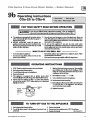
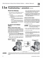
How it works ...
(j)
Control module
The control module responds to signals from the room thermostat and boiler limit circuit to operate the boiler
circulator, pilot burner, gas valve and vent damper. When room thermostat calls for heat, the control module starts
the system circulator and activates the vent damper (causing it to drive open).
When the vent damper has opened completely, the control module opens the pilot valve and activates pilot
ignition spark.
For natural gas, the control module allows up to IS seconds to establish pilot flame. If flante is not sensed within
IS seconds, the control module will turn off the gas valve, flash the Flame light, and immediately start a new cycle.
This will continue indefinitely until pilot flante is established or power is interrupted. Once pilot flante is proven,
the control module opens the gas valve to allow main burner flame.
For propane gas, the control module allows up to IS seconds to establish pilot flante. If flame is not sensed within IS
seconds, the control module will turn off the gas valve, flash the Flame light, wait I minute, then start a new cycle. If
flante is still not sensed after the second trial, two more attempts are made with S minute wait periods in between.
If flame is not sensed after 4 tries, control will lockout and flash all lights. Control must be manually reset to place
back into service. Once pilot flame is proven, the control module opens the gas valve to allow main burner flante.
When the room therntostat is satisfied, the control module turns off the gas valve and deactivates the vent damper
(causing it to dose).
The control module indicator lights show normal sequence when the lights are on steady. When a problem occurs,
the control module flashes combinations of lights to indicate the most likely reason for the problem. See page 49
for details.
(2)
@
Tr41nsfonner
The control transformer reduces line voltage to 24 volts for the gas valve and limit circuit.
Draft hood
The draft hood provides a minimum draft for the boiler, assuring adequate air for combustion if installed in
accordance with manual and not modified in any way.
@
Spill switch
The spill switch will shut down the boiler (requiring manual reset of the switch reset button) if the vent system
becomes blocked.
@
Water temperature sensor
The water temperature sensor l?rovides a signal to the control module to turn off the gas valve if the temperature
in the boiler goes above its settmg. (The circulator will continue to run as long as there is a call for h eat.)
@
®
Boiler circulator
The boiler circulator circulates water through the external (system) piping. The circulator is shipped loose, and
can be mounted on either the boiler suppfy or return piping. The factory-installed circulator wiring harness
provides ample length for either location. NOTE - The control module provides a pump exercising routine. If
the boiler is not operated for 30 days, the control module will power the circulator for 30 seconds, then turn off.
Vent damper
The vent damper closes during off cycles to reduce heat loss from the house up the vent.
Other boiler components:
a supply to system
b return from system
2
f
pressure/temperature gauge
k pilot burner, typical
g
relief valve
I
s tainless steel burners
c
flue outlet
burner manifold
h air vent connection
i flame rollout switclt
m cast iron boiler sections
d
n
flue collector
e
gasvalve
j
o
junction box
burner orifice
Part Number 550-142-779/0712
CGa Series 2 Gas-Fired Water Boiler -
Boiler Manual
CGa Series 2 Gas-Fired Water Boiler
Part Number 550-142-779/0712
3
COa Series 2 Gas-Fired Water Boiler -
Boiler Manual
Contents
How is works .................................................... 2-3
Hazard definitions ............................................... 4
Please read before proceeding ............................ 5
1
Prepare boiler location ...................................6-11
2
Prepare boiler............................................... 12-15
3
Water piping ................................................. 16-25
~
fi
Clas pipin!J ••••••••••••••••••••••••••••••••••••••••••••••••••••••••• 26
~ielcl wiring .••••...•••...•••...•••..••••...•••...•••...•••..••••.. 2~
6
Start-up ........................................................ 28-32
7
Check-out procedure ......................................... 33
8
Department of Energy Compliance ••••••••••••••••••• 34
9
Operation- spark-ignited pilot boilers ...•••...• 34-41
10
Service and maintenance ............................. 42-47
11
Troubleshooting:
Spark-ignited pilot boilers ............................ 48-56
12
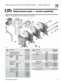
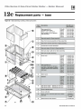
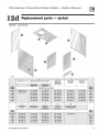
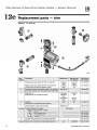
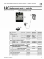
Replacement parts ....................................... 58-63
13
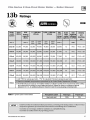
Dimensions and ratings ................................ 64-65
14
Notes ............................................................ 66-67
Hazard definitions
The following defined terms are used throughout this manual to bring attention to the presence of hazards of
various risk levels or to important information concerning the life of the product.
Indicates presence of hazards that will cause severe personal injury, death or substantial
property damage.
4
IAWARNINGI
Indicates presence of hazards that can cause severe personal injury, death or substantial
property damage.
lACAUTlONI
Indicates presence of hazards that will or can cause minor personal injury or property damage.
NOTICE
Indicates special instructions on installation, operation or maintenance that are important but
not related to personal injury or property damage.
Part Number 550-142-779/0712
CGa Series 2 Gas-Fired Water Boiler -
Boiler Manual
Please read before proceeding
Installer
User
I
Read all Instructions before Installing. Follow aU instructions in
proper order to prevent personal
injury or death.
Consider piping and Installation when determining
boiler location.
Any claims lor damage or shortage In shipment
must be filed immediately against the transportation
company by the consignee.
!A WARNING
This manual Is lor use only by your qualified
heating Installer/service technician.
Please refer to the user's Information Manual for
your reference.
We recommend regular service by a qualified
service technician, at least annually.
IAWARNINGI
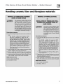
The boiler contains ceramic fiber and fiberglass materials. Use care when handling these
materials per instructions on page 57 of this manual. Failure to comply could result in severe
personal injury.
NOTICE
When calling or writing about the boiler- Please have the boiler model number from the
boiler rating label and the CP number from the boiler jacket. You may list the CP number in
the space provided on the Installation and service certificate found on page 33.
IAWARNINGI
Faih1re to ::.dhere to the Cllidel ine.s on this p::.ce (":tn re.snlt in severe personal injury, de.ath
or substantial property damage.
When servicing boiler To avoid electric shock, disconnect electrical supply
before performing maintenance.
To avoid severe burns, allow boiler to cool before
performing maintenance.
Boiler operation Do not block flow of combustion or ventilation air
to boiler.
Should overheating occur or gas supply fail to shut
off, do not turn off or clisconnect electrical supply to
circulator. Instead, shut off the gas supply at a location
external to the appliance.
Do not use this boiler if any part has been under water. Immediately call a qualified service technician to
inspect the boiler and to replace any part of the control
system and any gas control that has been under water.
Boiler water Do not use petroleum -based cleaning or sealing
compounds in boiler system. Water seal deterioration
will occur, causing leakage between sections. This can
result in substantial property damage.
Do not use "homemade cures" or "boiler patent
medicines". Serious dan1age to boiler, personnel and/
or property may result.
Part Number 550-142-779/0712
Continual fresh makeup water will reduce
boiler life. Mineral buildup in sections reduces heat transfer, overheats cast iron, and
causes section failure. Addition of oxygen
and other gases can cause internal corrosion.
Leaks in boiler or piping must be repaired
at once to prevent makeup water.
Do not add cold water to hot boiler. Thermal
shock can cause sections to crack
Glycol - potential fire hazard All glycol is flan1mable when exposed to high
temperatures.lf glycol is allowed to accumulate
in or around the boiler or any other potential
ignition source, a fire can develop. In order to
prevent potential severe personal injury, death
or substantial property damage from fire and/
or structural damage:
Never store glycol of any kind near the boiler
or any potential ignition source.
Monitor and inspect the system and boiler
regularly for leakage. Repair any leaks immediately to prevent possible accumulation
of glycol.
Never use automotive antifreeze or ethylene
glycol in the system. Using these glycols can
lead to hazardous leakage of glycol in the
boiler system.
5
COa Series 2 Gas-Fired Water Boiler -
1a
Boiler Manual
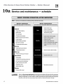
Prepare boiler location - codes & checklist
Installations must follow these codes:
Local, state, provincial, and national codes, laws, regulations and ordinances.
National Fuel Gas Code, ANSI Z223.!- latest edition.
Standard for Controls and Safety Devices for Automatically Fired Boilers, ANSI!
ASME CSD-1, when required.
National Electrical Code.
For Canada only: Bl 49.! or Bl 49.2 Installation Code, CSA C22.1 Canadian
Electrical Code Part I and any local codes.
NOTICE
The CGa boiler gas manifold and controls meet safe operating and
other performance criteria when boiler un denvent tests specified
in ANSI Z21.13- latest edition.
Before locating the boiler,
check the following:
Check for nearby connection to:
System water piping
Venting connections
Gas supply piping
Electrical power
Check area aroun d boiler. Remove any combustible materials, gasoline and
other flammable liquids, or other contaminants.
IAWARNINGI
Failure to keep boiler area dear and free ofcombustible materials,
gasoline and other flammable liquids and vapors can result in
severe personal injury, death or substantial property damage.
Boiler must be installed so that gas control system components are protected
from dripping or spraying water or rain during operation or service.
If new boiler will replace existing boiler, check for and correct system problems,
such as:
1. System leaks causing oxygen corrosion or section cracks from hard water
deposits.
2. Incorrectly-sized expansion tank.
3. Lack of antifreeze in boiler water causing system and boiler to freeze and
leak.
6
Part Number 550-1 42-779/0712
CGa Series 2 Gas-Fired Water Boiler -
1b
Boiler Manual
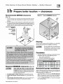
Prepare boiler location - clearances
Recommended SERVICE clearances
Figure 1b
Required MINIMUM clearances
(Fig. 1a)
1. Provide clearances for cleaning and servicing the boiler and for
access to controls and components. See Figure Ia for recommen·
dations.
2. Provide at least screwdriver clearance to jacket front panel screws
for removal of front panel for inspection and minor service. 1f
unable to provide at least screwdriver clearance, instaU unions and
shutoff valves in system so boiler can be moved for servicing.
Figure 1a
Recommended
service
clearances
(see WARNING
below)
Flooring
T he CGa boiler is approved for installation on combustible
flooring, but must never be installed on carpeting.
IAWARNINGI
II any clearance is less than in Figure 1a, provide openings for combustion and ventilation
air located on the wall or door oppoalts the
IAWARNINGI
boiler FRONT (aee Figure 1b).
These openings must be located as shown in Figure lb to provide
!?roper air flow around the boiler. The free area of each opening
{after deducting for louvers) must be at least one square inch
per 1,000 Btuh of boiler input. If the building is of unusually
tight construction (see page II for definition), the air openings
must connect direcdy to outside or the building must have air
openings to the outside as specified on page I I .
If clearances are equal to or greater than Figure Ia, see pages I0
and II for location and sizing of combustion air openings.
Failure to comply can result in severe personal injury, death or
substantial property damage and reduced boiler life.
Required MINIMUM clearances (Fig.1b)
Never Install the boller In a space with clearances less than the minimum clearances shown
In Figure 1 b. Failure to comply can result in severe
personal injury, death or substantial property damage and reduced boiler life.
1. Hot water pipes: at least 'h Inch from combustible material.
2. Single-wall vent pipe: at least Glnches from combustible material.
3. Type B double-wan metal vent pipe: refer to vent manufacturer's
recommendation for clearances to combustible material.
IAWARNINGI
Part Number 550-142-779/0712
Do not install boiler on carpeting even
if foundation is used. Fire can result,
causing severe personal injury, death
or substantial property damage.
Foundation
I. Provide a solid brick or m inimum 2-inch thick concrete
foundation pad if any of the following is true:
floor can become flooded.
the boiler mounting area is not level.
2. Minimum dimensions are 25" length by:
Minimum f oundation width:
CGa-2513
12"
CGa-6
21"
CGa-i
15"
CGa-7
24"
CGa-5
18"
CGa-8
27"
Residential garage installations
Take the following special precautions when installing the
boiler in a residential garage. If the boiler is located in a
residential garage, per ANSI Z223.1:
Mount the boiler a minimum of 18 Inches above the
floor of the garage to assure the burner and ignition
devices will be no less than 18 inches above the floor.
Locate or protect the boiler so it cannot be damaged
by a moving vehicle.
7
COa Series 2 Gas-Fired Water Boiler -
lc
IAWARNINGI
Boiler Manual
Prepare boiler location - vent system
Failure to follow all instructions can result in flue gas spillage and carbon monoxide emissions, causing severe
personal injury or death.
Inspect existing chimney before installing boiler. Failure to clean or replace perforated pipe or tile lining will cause
severe personal injury or death.
Do not alter boiler draft hood or place any obstruction or non-approved vent damper in breeching or vent system.
CSA certification will become void. Flue gas spillage and carbon monoxide emissions will occur causing severe
personal injury or death.
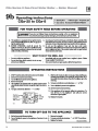
When removing boiler from an
existing common vent system:
Chimney or vent requirements
At the time of removal of an existing boiler, the following
steps shall be followed with each appliance remaining
connected to the common venting system placed in operation, while the other appliances remaining connected
to the common venting system are not in operation.
I. Venting must be installed according to Part 7, Vent-
a. Seal any unused openings in the common venting
system.
2. See Ratings table on page 665 for minimum chimney
or vent sizes. A chimney or vent without a lis ted
cap should extend at least 31eet above the highes t
point where it passes through a roof of a building
and at leas t 2 feet higher than any portion ol a
building within a horizontal dis tance 0110 feet.
A chimney or vent must not extend less than the
distances stated above.
b. VIsually Ins pect the venting system for proper
siu and ho•·izonral pitch and determine there is no
blockage or restriction, leakage, corrosion or other
deficiencies which could cause an unsafe condition.
c. Test vent s ystem- Insofar as is practical, close all
building doors and windows and all doors between
the space in wh ich the appliances remaining connected to the common venting system are located
and other spaces of the building. Turn on clothes
dryers and any appliance not connected to the common venting system. Turn on any exhaust fans, such
as range hoods and bathroom exhausts, so they will
operate at maximum speed. Do not operate a summer exhaust fan. Close fireplace dampers.
d. Place In operation the appliance being inspected.
Follow the operating instructions. Adjust thermostat
so appliance will operate continuously.
e. Tes t lor s pillage at draft h ood relief opening after
5 minutes of main burner operation. Use the flame
of a match or candle.
f.
After it has been determined that each appliance
remaining connected to the common venting system
properly vents when tested as outlined above, return
doors, windows, exhaust fans, fireplace dampers,
and any other gas-burning appliance to their previous conditions of use.
Any improper operation of common venting system
should be corrected so the installation conforms with
the National Fuel Gas Code, ANSI Z223.1-latest edition.
Correct by resizing to approach the minimum size as
determined using the appropriate tables in Part II of
that code. Canadian installations must comply with
Bl49.1 or Bl49.2 Installation Code.
8
ing of Equipment, ofNational Fuel Gas Code, ANSI
Z223.1-latest edition and applicable building codes.
Canadian installations must comply with Bl49.1 or
Bl49.2 Installation Codes.
3. A lined chimney is preferred and must be used when
required by local, state, provincial and national
codes, laws, regulations and ordinances. Vitreous tile
linings with joints that prevent retention of moisture
and linings made of noncorrosive materials are best.
Advice for flue connections and chimney linings can
be obtained from local gas utility. Type B doublewall metal vent pipe or single-wall vent pipe may
be used as a liner.
4. Cold masonry chimneys, also known as outside
chimneys, typically have one or more walls exposed to outside air. When any atmospheric gasfired boiler with automatic vent damper is vented
through this type of chimney, the potential e:<ists for
condensation to occur. Condensation can damage
a masonry chimney. Weil-Mclain recommends the
following to prevent possible damage.
a. Line chimney with corrosion-resistant metal
liner such as AL29-4C® single-wall s tainless
steel orB-vent. Size liner per National Fuel
Gas Code ANSI Z223.1 -latest edition.
b. Provide drain trap to remove any condensate.
5. Where rwo or more gas appliances vent into a
common chimney or vent, equivalent area should
be at leas t equal to area of vent outlet on largest
appliance plus 50 percent of vent outlet area on
additional appliance.
Part Number 550-142-779/0712
CGa Series 2 Gas-Fired Water Boiler -
1d
Boiler Manual
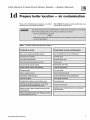
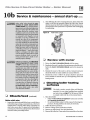
Prepare boiler location - air contamination
Please review the following information on potential
combustion air contamination problems.
IAWARNINGI
Refer to Table 1 for products and areas which may cause
contaminated combustion air.
To prevent potential of severe personal injury or death, check for products or areas listed
below before installing boiler. If any of these contaminants are found:
remove contantinants permanently
- OR isolate boiler and provide outside combustion air. See national, provincial or local codes
for further information.
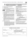
Table 1
Corrosive contaminants and likely locations
Products to avoid
Areas likely to have contaminants
Spray cans containing chlorolfluorocarbons
Dry cleaningnaundry areas and establishments
Permanent wave solutions
Swimming pools
Chlorinated waxes/cleaners
Metal fabrication olants
Chlorine-based swimming pool chemicals
Beauty shops
Calcium chloride used for thawing
Refrigeralion repair shops
Sodium chloride used for water softening
Photo processing plants
Refrigerant leaks
Auto body shops
Paint or varnish removers
Plastic manufacturing plants
Hydrochloric acid/muriatic acid
Furniture refinishing areas and establishments
Cements and glues
New building construction
Antistatic fabric softeners used in clothes dryers
Remodeling areas
Chlorine-type bleaches, detergents, and cleaning
solvents found in household laundry roorns
Garages wilh worl<shops
Adhesives used to fasten building products and other
similar products
Buildings under construction (Where air is contaminated
with particulates)
A irborne particulates (drywall dust, fiberglass particles,
road or gravel dust, lint, etc.)
Part Number 550-142-779/0712
9
COa Series 2 Gas-Fired Water Boiler -
1e
IAWARNINGI
Boiler Manual
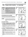
Prepare boiler location - air openings
Combus tion air opening location and s izing
requirements depend on the clearances around
the boller. Check the boiler placement compared to
Figure La, page 7.
It all clearances are at least equal to Figure 1a,
page 7, apply the sizing and placement of openings
given on pages 10 and 11.
It ANY clearance Is less than Figure 1a, page 7,
you must provide air openings sized and located as
shown in Figure lb, page 7. DO NOT apply the sizing
and location information shown on page 10 or 11.
Figure 2
Each opening free area =
1 sq. inch per 1,000 Btuh
"
Figure 3
Air openings must be provided
.
Figure 4
Two openings - Air supply from ins ide the building
*
10
Air from outdoors - vertical ducts
Outside or ventilat ed attic
Each opening tree arN =
1 sq. Inch per 4,000 Btuh
I. If the building is of unus ually tight construcllon (see definition, next
page), the building must also be provided with air openings directly
to the outside, sized and located per Figure 3, Figure 4 or Figure 5.
2. Buildings of typical construction should provide adequate combustion
air from natural infiltration, so additional air openings to the building
are not required.
3. See Figure 2. Provide two openings through the interior wall, within
12 inches of the ceiling and the floor, sized per Figure 2.
-
*
I. Air openings must be d irectly through an outside wall, or into a space
that connects directly to the outside (such as a ventilated attic or crawl
space, for example).
2. See Figure 3 - Openings directly through an outs ide wall-provide
two openings within 12 inches of the ceiling and the floor, sized per
Figure 3.
3. See Figure 4 - Air s upplied through vertical ducts - provide two
openings terminated within 12 inches of the ceiling and the floor, sized
per Figure 4.
4. See Figure 5 - Air s upplied through horizontal ducts - provide
two openings within 12 inches of the floor and the ceiling, sized per
Figure 5.
Ot 1r
...."'"', ..
assure proper combustion and reduce the risk of severe
personal injury, death or substantial property damage
caused by flue gas spillage and carbon monoxide
emissions.
Air opening options
=
1 sea. Inch per 4,000 Btuh
Provide adc::qualc wrnbw;tion and vc::ntilalion air to
Two openings - Air supply directly from outs ide
Air directly through outside wall
Each openfng free area
Combustion air and ventilation openings m ust comply the National Fuel
Gas Code ANSI Z223.1-latest edition, or applicable local building codes. Canadian installations must comply with Bl49.1 or Bl49.2 Installation Codes.
IA WARNINGl
Air openings to interior spaces
Figure 5
Air from outdoors - horizontal ducts
E.ac:h openi ng frM area •
1 sq. inch pat ~000 Btuh
0
--··
"'"''
~
0
Part Number 550-1 42-779/0712
CGa Series 2 Gas-Fired Water Boiler -
le
Prepare boiler location - air openings
FREE AREA of openings -
the minimum areas
given in this manual are free area (equals the area,
length times width of opening, after deduction for
louver obstruction).
Use the free area information provided by the louver manufacturer.
When this information is not available, assume:
Wood louvers- assume free area is 20o/o of total; so the actual area
of each opening with wood lou,•ers would be 5 times the required
free area.
Metal louvers- assume free area is 60o/o of actual area; so, for wood
louvers, the actual area of each opening must be 1.67 times the required free area.
NOTICE
Boiler Manual
Single air opening option
*
A s ingle combustion air open ing can be used in lieu of the two-opening
options on page 10, provided:
Clearances from boiler to walls
The boiler must have clearances of at least those shown in Figure Ia,
page 7.
Op&ning must b& dir&et/y to outside
The opening must connect directly to the o utdoors or to a space that
communicates directly to the outdoors (not to an interior space).
The air can be provided through a direct opening or through a horizontal
or vertical duct.
Op&ning p/ac&m&nt
The top of the air opening must be within 12 inches of the ceiling.
Op&ning siz&
The free area of the opening must be at least equal to the sum of the
area of all equipment vent connectors in the space, and ...
The free area of the opening must be at least I square inch per 3,000
BtuJhr input rating of all equipment located in the space.
Exception for large spaces
*
No combustion air openings are needed when the boiler (and other appliances) are installed in a space with a volume at leas t 50 cubic feet per
1,000 Btuh of all installed appliances, provided:
the building must not have unus ually tight cons truction (see definition, this page)
all clearances around the boiler must must be no less than sh own in
Figure Ia, page 7.
To determine if the space is large enough to qual ify:
Add the total input of aJI appliances in MBH (l,OOO's of Btuh).
Multiply this number times 50 to determine m inimum room volun1e.
Example: For a total input of 100 MBH (100,000 Btull), mininlum
volun1e is 50 x 100 = 5,000 cubic feet. At a ceiling height of 8 feet, the
space must have at least 5,000 + 8 = 625 square feet (25 feet x 25 feet,
for instance).
Part Number SSQ-142-77910712
Unusually tight construction
Unusually tight construction means (per ANSI Z223.1)
buildings in which:
a. Walls and ceilings exposed to the outside atmosphere have a continuous water vapor retarder with
a rating of I perm or less with openings gasketed,
and ...
b. Weather-stripping has been added on openable
windows and doors, and ...
c. Caulking or sealants are applied to areas such as
joints around windows and door frames, between
sole plates and floors, between wall-ceiling joints,
between wall panels, at penetrations for plumbing,
electrical, and gas lines, and in other openings.
For such construction cases, if appliances use inside air
for combustion, provide air openings Into the building
from outside. Size and locate these open ings per the
appropriate case in Figure 3, 4 or 5 on page 10.
l!xhaust fans and air movers
The appliance space must never be under a negative
pressure, even if the appliance(s) are installed as direct
vent. Always provide air openings sized not only to the
dimensions required for the firing rate of aU appliances,
but also to handle the air movement rate of the exhaust
fans or air movers using air from the building or space.
Motorized air dampers
If the air openings are fitted with motoriud dampers,
electrically interlock the damper to:
Prevent the boiler from firing if the damper is not
fully open.
Shut the boiler down should the damper dose during boiler operation.
To accomplish this interlock, wire an Is olate d contact
(proving the damper open) in series witll the thermostat input to the boiler. The boiler will not start if this
contact is open, and will shut down should it open
d uring operation.
II
COa Series 2 Gas-Fired Water Boiler -
2a
Boiler Manual
Prepare boiler - placement and setup
Place boiler/crate near
position
f 1M:!i@;l
1. Leave boiler In crate and on pallet until installation site is ready.
2. Move entire crate and pallet next to selected location.
3. Level and s traighten burners.
3. Remove crate. Leave boiler on pallet.
4. Remove boiler from pallet as follows:
a. Tilt left side of boiler up and place a board under
left legs.
b. Tilt boiler the other way and place a board under
right legs.
c. Slide boiler backwards off pallet and into position.
Do not drop boiler or bump jacket
NOTICE
on floor or pallet. Damage to boiler
can result.
5. Check level.
a. Shim legs, if necessary.
b. Do not alter legs.
I
Burners must be p roperly seated in
slots in burner rest with their openings face up. Main burner orifices
must inject down center of burner.
Failure to properly seat burners
will result in severe personal injury,
death or substantial property damage.
4. Reinstall access panel.
lACAUTlON I
Inspect orifices and burners
I. Remove front jacket door. Remove base access panel
(See Figure 32, item 4, page 60).
Correctly-sized manifold orifices
must be used. Failure to do so will
result in severe personal injury,
death or substantial property damage.
Do not operate boiler without access panel secured in place. Failure
to comply could cause momentary
flante rollout on ignition of main
flante, resulting in possible fire or
personal injury hazard.
Orifice replacement procedure
2. Check for correc tly-sized manifold orifices. See
Table 2 below for sizing. (The orifice size is stamped
on the orifice spud barrel.)
(when required)
Table 2
2. On gas manifold, mark location of main burner with
attached pilot assembly.
Manifo ld orifice s izing
Location
u.s.
Canada
Natural gas
0-2,000 ft
over 2,000 ft
2.00 mm
(Note 1)
G-2,000 ft
2,00G-4,500 ft
2.00 mm
1.90 nvn
Location
u.s.
Canada
Propane gas
0-2,000 ft
1.30
mm
over 2,000 ft
(Note 1)
G-2,000 ft
2,00G-4,500 ft
1.30 mm
1.20 nvn
Note 1: For elevations above 2,000 feet, contact your
Weii-Mclain sales office for details.
I. Remove access panel.
3. Remove main burner with attached pilot assembly
from manifold. Remove all remaining burners.
4. Remove and discard all main burner orifices in gas
manifold.
5. Apply a s maU amount of pipe dope to each of the
new orifices and install in the manifold. Make sure
the orifices are aligned correctly, not cross-threaded
in the manifold tappings.
IAWARNINGI
Use only p ipe dope compatible with
propane gas, even if boiler is to be
operated on natural gas. Failure to
comply could result in severe personal injury, death or substantial
property damage.
6. Reinstall main burner with attached pilot assembly
at location marked on gas manifold. Reinstall all
remaining burners.
7. Follow check-out procedure, Section 7, page 33.
12
Part Number 550-142-779/0712
CGa Series 2 Gas-Fired Water Boiler -
2b
Boiler Manual
Prepare boiler - pressure test
Hydrostatic pressure test
Pressure test boiler before attaching water or gas piping
or electrical supply (except as noted below).
Prepare boiler for test
I. Remove the shipping nipple (from CGa supply
tapping) and remove the boiler relief valve.
Temporarily plug the relief valve tapping with a%"
NPT pipe plug.
2. Remove I \14" nipple, reducing tee and drain
valve from accessory bag. InstaU in boiler return
connection as shown on page 3 or in Figure 34, item
3, page 62. Install circulator on either the return or
supply.
3. Remove I \14" nipple, I \14" tee, bushing and pressure/
temperature gauge from accessory bag. Pipe to
boiler supply connection as shown in Figure 34,
page 62-. (Use pipe dope sparingly.)
4. Connect a hose to boiler drain valve, the other end
connected to a fresh water supply. Make sure hose
can also be used to drain boiler after test.
5. Connect a nipple and shutoff valve to system supply
connection on the I \14" tee. This valve will be used
to bleed air during the fill. (Valve and nipple are
not included with boiler.)
6. Connect a nipple and shutoff valve to system
return connection (at circulator flange if circulator
installed on return). This valve will be used to
bleed air during the fill. (Valve and nipple are not
included with boiler.)
Fill and pressure test
1. Open the shutoff valves you installed on supply and
return connections.
2. Slowly open boiler drain valve and fresh water
supply to fill boiler wid1 water.
3. When water flows from shutoff valves, close boiler
drain valve.
Part Number 550-1 42-779/0712
4. Close shutoff valves.
5. Slowly reopen boiler drain valve until test pressure
of not more than 45 psi is reached on the pressure/
temperature gauge.
6. Test at no more than 45 psi lor no more than 10
minutes.
Do not leave boller unattended.
IAWARNINGI
A cold water fill could e>.-pand and
cause excessive pressure, resulting
in severe personal injury, death or
substantial property damage.
7. Make sure constant gauge pressure has been maintained throughout test. Check for leaks. Repair if
found.
IAWARNINGI
Leaks must be repaired at once.
Failure to do so can damage boiler,
resulting in substantial property
damage.
Do not use petroleum-based cleaning or sealing compounds in boiler
system. Severe damage to boiler
will occur, resulting in substantial
property damage.
Drain and remove fittings
I. Disconnect fill water hose from water source.
2. Drain boiler at drain valve or out hose, whichever
provides best access to drain. Remove h ose after
draining if used to drain boiler.
3. Remove nipples and valves unless they will remain
for use in the system piping.
4. Remove plug from relief valve tapping. See Section 3
to replace relief valve.
13
CGa Series 2 Gas-Fired Water Boiler -
2C
Boiler Manual
Prepare boiler - draft hood & spill switch
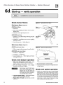
Draft hood installation
Spill switch installation
1. Orient draft hood with spill switch mounting holes to front of boiler
as shown in Figure 7.
2. Secure draft hood to outlet a t top of boiler with sheet metal screws.
3. Bottom of draft hood or "skirt" must have clearance dimension above
jacket top panel as indicated on draft hood.
j1 1MHij@ ;I
Do not alter boiler draft hood or place any obstruction or
- - -···-· ••
non-approved vent damper in breeching or vent system.
CSA certification will become void. Rue gas spillage and
carbon monoxide emissions will occur causing severe
personal injury or death_
I. Fasten spill switch to draft hood as shown in Figure 6
and Figure 7.
p
Figure 6
2. See Wiring diagram to connect wires:.
a_
Spark-ignited pilot boilersee pages 36 and 37
IAWARNINGI
Improper orientation of spill switch
may cause boiler to shut down. The
loss of heat can result in significant
damage due to freezing.
Figure 7 Spill switch with wire harness
Install spill switch
Spill switch w ire
harness
•
Damper harness
D"ft hood_/
knockout - -"'
.....
2d
Prepare boiler - install vent piping
I. Connect from draft hood or vent damper outlet to chimney or vent
IAWARNINGI
14
LQng horizontal vent coJmector,
excessive number of elbow or
tees, or other obstructions that
restrict the flow of combustion
gases should be avoided. Severe
personal injury, death or substantial property damage could result
with same size vent connector.
2. Where possible, vertical venting to the outside from the draft hood or
vent damper outlet will offer best performance.
3. Where horizontal vent connector is used, slope upward at least \4'' per
lineal foot toward chimney or vent and support with hangers to prevent
sagging.
4. Breeching mus t not be connected to any portion of a mechanical draft
system that can operate under positive pressure.
Part Number 550-1 42-779/0712
CGa Series 2 Gas-Fired Water Boiler -
2e
Boiler Manual
Prepare boiler - vent damper installation
NOTICE
These systems are used on gas-fired boilers with vent
dampers as shipped from factory. Boiler will not operate
without vent damper installed.
IAWARNINGI
Only vent dampers listed in the Replacement parts list
on page 58 are certified for use wid1 CGa boilers. Any
other vent damper installed could cause severe personal
injury or death.
Installation
I. Install vent damper horiwntally or vertically as
shown in vent damper manufacturer's instructions.
Vent dan1per must be installed so that it serves only
one boiler and so damper blade indicator is visible
to the user. See Figure 8.
2. Screws or rivets used to secure the vent damper to
the draft hood must not interfere with rotation of
the damper blade.
Damper blade
Spark-Ignited pilot systems- Refer to vent manufacturer's instructions to install plug (shipped with
damper) in damper hole. For spark-ignited pilot
boilers only, install plug with no hole in vent damper
hole.
3. Install damper harness between damper actuator
and knockout in jacket top panel. Use strain relief
connectors and locknuts to secure both ends of
damper harness.
!ACAUTION I
Keep wiring harness clear of all hot
surfaces.
WARNING
Minimum clearances
UNE UP KEYWAY WHEN
CONNECTING PLUGS.
Provide a minimum of 6" between fue vent damper and
any combustible material. (Provide a minimum of 36 "
between jacket top and combustible ceiling.)
Do not modify draft hood or vent damper, or make another connection between draft hood and vent damper
or boiler except as noted below. This will void CSA
certification and will not be covered by Weil-McLain
warranty. Any changes will cause severe personal injury,
death or subs tantial property damage.
Figure 8
FORCING A MISMATCH
CAN CAUSE A
HAZARDOUS CONDITION.
oo
OQ
Keyway~-- .. . ····-···-····· --L_ Key
59304
4. Read and apply the harness plug warning label
(shown above) so that it is visible after installation.
5. Plug damper harness receptacle into damper harness
plug.
Vent damper assemblies
Effikal or Field Controls
Johnson Controls damper
damper
Refer to vent manufacturer's instructions to install
Bypassing (jumpering) vent damper
w ill cause flue products such as
carbon monoxide to escape into
the house. This will cause severe
personal injury or death.
plug {shipped with damper) in damper hole.
Hold-open switch {Effikal onlyI Install vent damper so that switch
is visible and accessible to user.
Part Number 550-142-779/0712
S932S
!ACAUTION I
After boiler has operated once, if either end of harness is disconnected,
the system safety shutdown will occur. The boiler will not operate until
harness is reconnected.
NOTICE
E111kal or Field controls damperDan1per hold open switch must be
in Automatic Operation position
for system to operate properly.
IS
COa Series 2 Gas-Fired Water Boiler -
3a
Boiler Manual
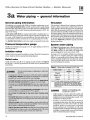
Water piping - general information
General piping information
Circulator
If installation is to comply with ASME or Canadian requirements, an additional high temperature limit is needed. Install control in supply piping
between boiler and isolation valve. Set second control to minimum 20°F
above setpoint of first control. Maximum allowable setpoint is 240°F. See
page 36, for wiring.
Use backllow Check valve in cold water supply as required by local codes.
T he circulator is shipped loose (wiring pre-attached to
boiler) to allow you to locate it either in the return or
supply piping, as desired. See page 3 for a typical installation. Pipe the expansion tank to the suction side of the
circulator whenever possible. Install an air separator in
the supply piping. Connect the expansion tank to the air
separator only if the separator is on the suction side of
the circulator. Always install the system fill connection
at the same point as the expansion tank connection to
the system. Figures 9 and 10 show typical near-boiler
piping connections.
Pressure/temperature gauge
System water piping
Install pressure/temperature gauge in tee on supply piping (as shown in
drawing on page 3).
See Figure 9 (diaphragm-type or bladder-type expansion tank) or Figure 10 (dosed-type expansion tank),
and Table 3 below, for near-boiler and single-zone
systems designed for return water at least 130°F.
See pages 18-19 to complete multiple-zone piping or
pages 20-25 to complete piping for radiant heating
systems or converted gravity systems (large-volume
systems originally designed for circulation by natural
convection rather than a pump). Sec pa~;e 25 fur boiler>
used with refrigeration systems.
A low water cutoff device is required when boiler is installed above radiation level or by certain state or local codes or insurance companies. Use
low water cutoff designed for water installations. Electrode probe-type is
recommended. Purchase and install in tee in supply piping above boiler.
Isolation valves
Isolation valves are required to enable servicing of the boiler's temperature
sensor. Install as shown in appropriate piping diagram.
Relief valve
Install relief valve vertically in %• tapping on side of boiler. See Figure 9
or 10, page 17, and the tag attached to the relief valve for manufacturer's
instructions.
Table 3
lAWARNING!
To avoid water damage or scalding due to relief valve
operation:
Discharge line must be connected to relief valve outlet and run to
a sale place of disposal . Terminate the discharge line to eliminate
possibility of severe burns should the valve discharge.
Discharge line must be as short as possible and be the same size as
the valve discharge connection throughout its entire length.
Discharge line must pitch downward from the valve and terminate
at least 6" above the floor drain where any discharge will be clearly
visible.
The discharge line shall terminate plain, not threaded, with a material serviceable for temperatures of 375°F or greater.
Do not pipe the discharge to any place where freezing could
occur.
No shutoff valve shall be installed between the relief valve and boiler,
or in the discharge line. Do not plug or place any obstruction in the
discharge line.
Failure to comply with the above guidelines could result in failure of
the relief valve to operate, resulting in possibility of severe personal
injury, death or substantial property damage.
Test the operation of the valve after filling and pressurizing system
by lifting the lever. Make sure the valve discharges freely. If the valve
fails to operate correctly, replace it with a new relief valve.
16
Water pipe size (based on 20°F rise)
Boiler model
CGa-25
CGa-3, 4, 5
CGa-6, 7
CGa-8
To
system
:Y.."
From
system
%"
1"
1..
1%''
1%"'
11h''
1V2"
Note: The boiler supply and return connections, the retuml
drain tee and the supply/gauge tee supplied with
the boiler are 1 14'' NPT. One of the circ ulator flanges
supplied with the boiler is 114•. The other c irculator
flange is the size of the recomm ended system piping
shown aboVe.
lAWARNING!
Chillers or air handling units:
Install boiler such that-
Chilled medium, if used, is piped in parallel with
heating boiler. Use appropriate valves to prevent
chilled medium from entering boiler. Consult AHRI
Installation and Piping Guides.
If boiler is connected to heating coils located in
air handling units where they can be exposed to
refrigerated air, use flow control valves or other
automatic means to prevent gravity circulation
during cooling cycle. Circulation of cold water
through the boiler could result in damage to the heat
exchanger, causing possible severe personal injury,
death or substantial property damage.
Part Number 550-142-779/0712
CGa Series 2 Gas-Fired Water Boiler -
3b
Boiler Manual
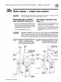
Water piping - single-zone system
lACAUTlON I
Undersized expansion tanks cause system water to be lost from relief valve and makeup water
to be added through fill valve. Eventual section failure can result.
Diaphragm-type or bladdertype expansion tank (Figure 9)
Closed-type expansion tank
I. Ensure expansion tank size will handle boiler and
I. Ensure expansion tank size will handle boiler and
system water volume and temperature. Tank must
be located in boiler return p ipmg as d ose to boiler
as possible, before inlet side of circulator. See tank
manufacturer's instructions for details.
2. Install an automatic air vent as shown.
IAWARNINGI
Figure 9
(Figure 10)
system water volume and temperature. See tank
manufacturer's instructions for details.
2. Connect tank to Ih" NPT tapping located behind
supply outlet, using W' NPT p iping. Pitch any
horizontal piping up towards tank I inch per 5 feet
of piping.
Use Figure 9 or Figure 10 only for single-zone systems designed for return water at least
130•F. For systems with low return water temperature possible, such as converted gravity
systems and radiant h eating systems, refer to the special piping suggestions of pages 20-25.
Failure to prevent low return water temperature to the boiler could cause corrosion of the boiler
sections or burners, resulting in severe personal injury, death or substantial property damage.
Diaphragm- or bladder-type expansion tank - Single-zone system using
diaphragm-type or bladder-type expansion tank. See Table 3 for piping s izes.
From
system
Figure 10
Closed-type expansion tank - Singlezone system using closed-type expansion tank. See Table 3 for piping sizes.
Cold
water
fill
To DIAPHRAGM
expansion tank
and fittings
Isolation
valve
lsola t i /
valve
Relief
valve
Isolation
valve
To system
To system
Relief
valve
Circulator*
91,.__,.""___ Automatic
air vent
Circulator
..,.,
*Alternate
location
Circulator
*Alternate
location
Part Number 550-142-779/0712
17
COa Series 2 Gas-Fired Water Boiler -
3c
Boiler Manual
Water piping - multiple zones
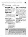
Piping multiple zones
Follow instructions on pages 16 and 17 to install nearboiler or single-zone piping. (Also refer to Piping
tor radiant heating s ys tems or converted gravity
s ystems, below, if applicable.)
See Figure 11 or Figure 12, page 19, to complete installation.
Zoning with circulators (Figure 11)
(return temp over 130"F)
I. Size each circulator to individual circuit requirements.
2. Do not install circulator on boiler (except for
primary/secondary piping).
3. Install isolation (balancing) valves to adjust flow to
distribute heat to all zones.
4. Install and wire a separate relay for each zone
circulator.
Zoning with zone valves (Figure 12)
(return temp over 130•F)
I. Install isolation (balancing) valves to adjust flow to
distribute heat to all zones.
2. Provide a separate 24-volt transformer to power the
zone valves. Size the transformer to h andle the total
rated load of all connected zone valves.
IAcAunoNI
IAWARNINGI
DO NOT connect directly fro m
3-wire zone valves t o the T-T termina ls on the boiler. \¥hen using 3-wire
zone valves, install an isolation relay.
O:mnect the zone valve end switch wires
to the isolation relay coil. Connect the
isolation relay contact across the boiler
T-T terminals. Failure to comply can
result in damage to boiler components
or cause unreliable operation, resulting
in severe property damage.
Piping for radiant heating
systems or converted gravity
systems
Converted gravity (or steam) systems
\¥henever possible, use the primary/secondary piping
shown in Figures 13 or 14 on page 21. This piping design allows changing boiler flow rate without affecting
primary circuit flow rate.
If Figures 13 or14cannot be used, use the boiler-bypass
piping shown in Figure 15 or Figure 16 on page23. You
can also use the pifing s hown in Figure 17 on page 25
(system-bypass), i the reduced flow rate in the heating
system will not cause heat distribution problems.
IAWARNINGI
Failure to prevent low return water
temperature to the boiler could cause
corrosion of the boiler sections or burners, resulting in severe personal injury,
death or substantial property damage.
Radiant heating systems
Preferably, use primary/secondary piping, as shown
in Figures 13 or 14 on page 21. Alternatively, use the
method of either Figure 15 or Figure 16 on page 23.
Do not use the piping of Figure 17 (system-bypass),
because this method does not control radiant system
supply temperature.
If radiant system tubing has no oxygen barrier, a heat
exchanger must be used.
Rad iant heating system piping should include a means of regulating the boiler return water
temperature and the system supply temperature (such as provided by an injection pumping
control). Boiler return water temperature will be adequately controlled using the methods
shown in th is manual provided the system supply temperature is relatively constant.
DO NOT apply the methods in this manual if the system is equipped with an outdoor reset
control . Instead, provide controls and piping which can regulate the boiler return water
temperature at no less than 130"F regardless of system supply temperature. Contact your
Weii-McLain representative for suggested p ip ing and control methods. Failure to prevent
cold return water temperature to the boiler could cause corrosion damage to the sections or
burners, resulting in possible severe personal injury, death or substantial property damage.
18
Part Number 550-1 42-779/0712
CGa Series 2 Gas-Fired Water Boiler -
3c
Boiler Manual
Water piping - multiple zones
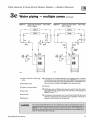
Figure 11
Zoning with c irculators - return water
130°F or higher.
Figure 12
Zoning with zone valves - return water
130°F or higher.
r-------------..
++----------------~---~e~N-e:z--1-----------------++
'
______________..
'
_,:'-------<--------,'
~
I!
~
ZONE 1
~
~
1
<continued)
Z0 NE 2
'r---------o-----+~.
--------------J
I
I
I!
ZONE 1
r ..1
1
I
I
Lr•
~
~
2
Lr l
(' T )'
1
~~
~
6
6
13
10
C<Jid
C<Jid
water
fil
wate.r
fill
15:1
ill
iii
.,,,.
'"""
1 Boiler isolat ion (balancing)
1 0 Automatic air vent (with diaphragm-type expansion tank), or connect
to tank fitting (closed -type e:q>ansion tank). DO NOT use an automatic
air vent when using closed-type expansion tank. It would allow air to
leave the system, causing waterlogging of the expansion tank.
valves
2 Flow/check valve
11 Fill valve
3 System or zone circulator
5 Zone valve
6 Drain valve
9 Relief valve
lAWARNING!
Part Number 550-142-779/0712
12 Diaphragm-type or bladder-type expansion tank, if used (For dosedtype e>:pansion tank, pipe from top of air separator to tank fitting as in
Figure 10,page 17.)
13 Air separator and automatic vent, if used (Note that the fill valve must
always be connected to the exyansion tank, regarclless of location of
expansion tank circulator or a1r separator.
For systems with possible low return-water temperature (such as converted gravity systems,
racliant heating systems and heat pump systems), refer to the special piping suggestions of
Figures 13 - 17, as applies. Failure to prevent sustained low return water temperature to
the boiler could cause corrosion of the boiler sections, resulting in severe personal injury,
death or substantial property damage.
19
COa Series 2 Gas-Fired Water Boiler -
3d
Boiler Manual
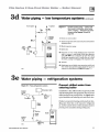
Water piping- low temperature systems
Primary/secondary (preferred)
Bypass piping method
Primary/secondary bypass piping is preferred because
the flow rate and temperature drop in the heating
circuit(s) is determined only by the h eati ng circuit
circulator(s). So adjustment of the bypass valves in
the boiler circuit wiU not cause a change in the heating
circuit rate and temperature distribution.
Figures 13 and 14, page 21, show suggested bypass
arrangements using primary/secondary bypass piping
(preferred) for low temperature systems such as radiant
heating systems or converted gravity systems. For
alternatives, see pages 22 through 25.
The bypass valves (items 7a and 7b) provide mixing of
ho t boiler outlet water with cooler system return water
- set to assure a minimum return water temperature
(at least 130°F) to the boiler. Set the valves as explained
below.
water temperature being supplied to the radiant tubing.
Gauge 8 is required on all systems to assure the return
water temperature is accurately set for a minimum of
I 30°F. If this gauge is not available however, adjust the
valves such that the boiler-mounted temperature/pressure gauge reads at least I so•F when the system return
water is cold (approximately 60°F water temperature).
Valve adjustment
(Figures 13 and 14 only)
I. Set the valves while the system is cool, setting for the
coldest expected water temperature (usuaUy 60°F
since the system will often drop to room temperature berween cycles).
2. Start with valve 7a fully closed and 7b fully open.
3. GraduaUy open valve 7a while closing valve 7b until
the temperature at gauge 8 reads I 30°F when gauge
4a reads 60°F.
Temperature gauges
Gauge 4a is suggested, but optional on any system.
Gauge 4b is optional on converted gravity systems, but
required on radiant heating systems - to display the
IAWARNINGI
20
4. Note that valve 7a regulates the amount of hot water from the boiler supply which mixes with return
water. Valve 7b regulates the amount of system water
flowing through the boiler secondary loop.
Failure to prevent low return water temperature to the boiler could cause corrosion
of the boiler sections or burners, resulting in severe personal injury, death or substantial
property damage.
Radiant heating system piping should include a means of regulating the boller return
water temperature and the system supply temperature (such as provided by an InJection pumping control).
Boiler return water temperature will be adequately controlled using the methods shown
in this manual provided the system supply temperature is relatively constant.
DO NOT apply the methods of this manual if the system is equipped with an outdoor reset
control. Instead, provide controls and piping which can regulate the boller return water
temperature at no less than 130•F regardless of system supply temperature. Contact your
Weil-McLain representative for suggested piping and control methods.
Failure to prevent cold return water temperature to the boiler could cause corrosion
damage to the sections or burners, resulting in possible severe personal injury, death or
substantial property damage.
Part Number 550-1 42-779/0712
CGa Series 2 Gas-Fired Water Boiler -
3d
Boiler Manual
Water piping - low temperature systems (continued)
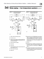
Figure 13
Primary/secondary piping
Zoning with c irculators
Figure 14
Primary/secondary piping
Zoning with zone valves
~----~-------r---z:c>NE-2--:L------~-------------~t
"----------_J
T
I
ZONE 1
I
I
1$
,
,...,
I
~~i
I
.~
fD
I
-t....,.
_.;
e
7b
Atr~nat&
8
"""""''
loc4tion
C<>ld
w atet
fill
10
ill
.,,,
,,.,.
1
Boiler isolation (balancing) valves
2
Flow/check valve
3 System or zone circulator (circulator should cycle
with zone valve and switches, using circulator valve
or zone control panel)
10 Automatic air vent (with diaphragm-rype expansion
tank), or connect to tank fitting (closed-rype expansion tank). DO NOT use an automatic air vent when
usi ng closed-type expansion tank. It would allow
air to leave the system, causing waterlogging of the
expansion tank.
4
System temperature gauges
1 1 Fill valve
5
Zone valve
12 Diaphragm-rype or bladder-rype expansion tank,
6
Drain valve
if used (For d osed-type expansion tank, pipe from
top of air separator to tank fitting as in Figure 10,
page 17.)
7 System temperature valves (see instructions to the
left for adjusting valves)
8
Blend temperature gauge
9
Relief valve
Part Number 550-1 42-779/0712
13 Air separator and automatic vent, if used (Note that
the fill valve must always be connected to the expansion tank, regardless of location of expansion tank,
circulator or air separator.)
21
COa Series 2 Gas-Fired Water Boiler -
3d
Water piping - low temperature systems <continued)
BOILER-bypass piping
method
This piping method (Figure 15 or 16, page 23) is called
a boller-bypass because part of the circulator flow is
bypassed around the boiler (through valve 7a). This
method reduces the flow rate throughout the boiler, in
order to raise the average water temperature in the boiler
enough to prevent flue gas condensation. Boiler-bypass
piping is effective for some boilers - including the
CGa - provided the flow rates are adjusted according
to the instructions following.
Figures 15 and 16 are alternative piping suggestions
for converted gravity (large water content or steam
systems) or radiant heating system- for use when
primary/secondary piping can't be applied. (Figure 17,
page 25, is another alternative, using system bypass in
place of boiler-bypass piping. Figure 17 however, is
not suitable for radiant heating applications because it
does not protect the radiant system from possible high
water temperature.)
Boiler-bypass piping keeps system flow rate as high as
possible and temperature drop as low as possible, helping to equaliu the building heat disn·ibution.
Temperature gauges
Gauge 4a is optional if the bypass valves will be adjusted using cold (or room temperature) return water
IAWARNINGI
22
Boiler Manual
to the boiler. (\¥hen setting the valves without gauge
4a installed - using cold or room temperature water
- assume the return water temperature to be 60°F. Set
the valves so gauge 8 reads at least I20°F.
Gauge 4b is optional on converted gravity systems, but
required on radiant h eating systems - to display the
water temperature being supphed to the radiant tubing.
Gauge 8 is required on aU systems to assure reliable
adjustment of the bypass valves. The boiler-mounted
temperature/pressure gauge can be used if a separate
temperature gauge is not installed.
Valve adjustment
I. Start with valve 7a fully closed and 7b fully open.
2. Gradually open valve 7a while closing valve 7b
until the temperature at gauge 8 reads 60 •F higher
than gauge 4a. A minimum 60"F temperature rise
through the boiler assures a low enough flow rate
and high enough average temperature to prevent
condensation even with low system return water
temperature.
3. Valve 7a regulates the system flow rate, while valve
7b regulates the boiler flow rate.
4. The boiler-mounted temperature/pressure gauge
may be used in place of a separate gauge 8.
Failure to prevent low return water temperature to the boiler could cause corrosion
of the boiler sections or burners, resulting in severe personal injury, death or substantial
property damage.
Radiant heating system piping should include a means of regulating the boller return
water temperature and the s ys tem supply temperature (such as provided by an InJection pumping control) .
Boiler return water temperature will be adequately controlled using the methods shown
in this manual provided the s ystem s upply temperature is relatively constant.
DO NOT apply the methods of this manual if the system is equipped with an outdoor reset
control. Instead , provide controls and piping which can regulate the boller return water
temperature at no less than 130•F regardless of system supply temperature. Contact your
Weil-McLain representative for suggested piping and control methods.
Failure to prevent cold return water temperature to the boiler could cause corrosion
damage to the sections or burners, resulting in possible severe personal injury, death or
substantial property damage.
Part Number 550-142-779/0712
CGa Series 2 Gas-Fired Water Boiler -
3d
Boiler Manual
Water piping - low temperature systems (continued)
Figure 15
Boiler-bypass piping
Zoning with c irculators
(Alternative to primary/secondary p ip ing
Figure 16
Figures 13 and 14)
Figures 13 and 14)
,..-----------,
.('------------i_ ZONE 2 ~-----------------~
-------------~
'
I
'
I
ZONE 1
fJi:
~~
1
'
r~
r------------,
-+-------------~
f
ZONE 2
~-----------+t
ZONE 1
:1
L------------•
1:
·
,...,
~
I
4a
Lt
Boiler-bypass piping
Zoning with zone valves
(Alternative to primary/secondary piping
If
-~'
6
II
!19312
'""'
1
Boiler isolation (balancing) valves
2
Flow/check valve
3
System or zone circulator
4
System temperature gauges
5
Zone valve
6
Drain valve
7 System temperature valves (see instructions
to the left for adjusting valves)
10 Automatic air vent (with diaphragm-type expansion
tank), or connect to tank fitting (closed-type expansion
tank). DO NOT use an automatic air vent when using
closed-type expansion tank. It would allow air to leave
the system, causing waterlogging of the expansion tank.
11 Fill valve
12 Diaphragm-type or bladder-type e>.-pansion tank, if
used (For closed-type expansion tank, pipe from top
of air separator to tank fitting as in Figure 10.)
13 Air separator and automatic vent, if used (Note that the
8
Blend temperature gauge
9
Relief valve
Part Number 550-142-779/0712
fill valve must always be connected to the expansion
tank, regardless oflocation of expansion tank, circulator
or air separator.)
23
COa Series 2 Gas-Fired Water Boiler -
3d
Boiler Manual
Water piping - low temperature systems <continued)
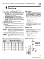
SYSTEM-bypass piping
method
This piping method (Figure 17, page 25) is called a
system-bypass because part of the circulator flow bypasses the system (through valve 7 a ). This bypassed hot
water from the boiler outlet mixes with cooler system
return water temperature in order to provide minimum
130°F return water to the boiler. Valve 7b wiU most often
be full open, but may need to be slightly closed on some
low pressure drop systems in order to cause enough flow
through valve 7a .
Figure 17 is an alternative piping method that provides
return water temperature control for boilers installed
on converted gravity s ys tems (large water content
or steam systems).
DO NOT apply the piping of Figure 17 on radiant
heating systems. It provides no method of regulating the water temperature provided to the system and
could result in excessive water temperature in the radiant tubing.
System-byp•,;s pi pine M shown in Flguro 17 <:>1n be 11sed
with either zone valve or circulator zoning. When used
with circulator zoning however, the boiler circulator
(item 3), must be piped as shown. It cannot be used as
one of the zoning circulators.
IAWARNINGI
DO NOT apply system-bypass piping if the reduced
flow in the system could cause poor heat distribution.
That is, system -bypass piping reduces the flow in the
system and increases the water temperature supplied to
the system. This can cause increased heat from radiators
at the beginning of the system and reduced heat from
radiators near the end of the system.
Valve adjustment
I. Start with valve 7a fully closed and 7b fully open.
2. Gradually open valve 7a while closing valve 7b until
the temperature at gauge 8 reads at least 130°F at all
times.
3. Valve 7a regulates the amount of boiler supply water
mixed wid1 return water. Valve 7b causes a pressure
drop in the system needed to balance flow through
valve 7a and the system.
4. Th e valve adjustment should be done with the
system at the coldest expected temperature ( 60°F
for converted gravity systems or high mass radiant
systems).
Failure to prevent low return water temperature to the boiler could cause corrosion
of the boiler sections or burners, resulting in severe personal injury, death or substantial
property damage.
Radiant heating system piping should include a means of regulating the boller return
water temperature and the system supply temperature (such as provided by an InJection
pumping control).
Boiler return water temperature will be adequately controlled using the methods shown
in this manual provided the s ystem s upply temperature is relatively constant.
DO NOT apply the methods of this manual if the system is equipped with an outdoor reset
control. Instead , provide controls and piping which can regulate the boller return water
temperature at no less than 130°F regardless of system supply temperature. Contact your
Weil-McLain representative for suggested piping and control methods.
Failure to prevent cold return water temperature to the boiler could cause corrosion
damage to the sections or burners, resulting in possible severe personal injury, death or
substantial property damage.
24
Part Number 550-142-779/0712
CGa Series 2 Gas-Fired Water Boiler -
3d
Boiler Manual
Water piping - low temperature systems (continued)
From system
To system
Alternate
circulator
location
8
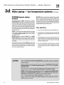
Figure 17
System-bypass piping - Zoning with
zone valve or c irculators, retum water
130°F or higher - (Alternative to boilerbypass piping Figures 15 a nd 16,
page 23)
3 System o r zone circulator
7 System temperature valves (see instructions to the left for
adjusting valves)
8 Blend temperature gauge
9 Relief valve
12 3
10 Automatic air vent (with diaphragm-type expansion
tank), or connect to tank fitting (closed-type expansion
tank). DO NOT use an automatic air vent when using
d osed-type expansion tank. It would allow air to leave
the system, causing waterlogging of the expansion tank.
11 Fill valve
12 Diaphragm-type or bladder-type expansion tank, if used
(For closed-type expansion tank, pipe from top of air
separator to tank fitting as in Figure 10, page 17.)
..,,.
3e
Water piping - refrigeration systems
Figure 18 Piping refrigeration systems
-
Circulator
I) Expansion tank
Cl
System
supply
t
I
- .L
Shut-off
valve
~
Water
chiller
t
D- Strainer
System
return
~
""'"
Part Number 550-142-779/0712
•
t
Check
valve
Boiler
Prevent chilled water from
entering boiler
Install boiler so that chilled medium is piped in parallel
with the heating boiler. Use appropriate valves to prevent
chilled medium fro m entering boiler. See Figure 18 for
typical installation of balancing valve and check valve.
If boiler is connected to heating coils located in air handling units where they can be exposed to refrigerated
air, use flow control valves or other automatic means to
prevent gravity circulation during cooling cycle.
El:l
EIEI
~
e aii;ncing
valve
25
COa Series 2 Gas-Fired Water Boiler -
4
Boiler Manual
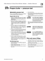
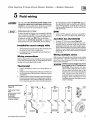
Gas piping
Connect gas supply piping to boiler
Natural Gas:
l. Remove jacket front panel and refer to Figure 19 to pipe gas to boiler.
I. Refer to Table 4 for pipe length and diameter. Base
on rated boiler input (divide by I ,000 to obtain cubic
feet per hour). Table 4 is only for gas with s pecific
gravity 0.60, with a pressure drop through the
gas piping of 0.30" w.c. For additional gas pipe
sizing information, refer to ANSI Z223.1 (or Bl49.1
or Bl49.2 for Canadian installations).
a. Ins tall drip leg at inlet of gas con nection to boiler. Where local
utility requires drip leg to be extended to the floor, use appropri·
ate length of pipe between cap and tee.
b. Ins tall ground joint union for servicing, when required.
c. Ins tall manual s hutoff valve in gas supply piping outside boiler
jacket when required by local codes or utility req uirements.
d. In Canada -
When using 1nanual main shutoff valve, it mus t be
Identified by the installer.
2. Support piping with hangers, not by boiler or its accessories.
3. Purge all air from gas supply pipi ng.
4. Before placing boiler in operation, c heck boiler and Its ga s connec-
tion for leaks .
a. Close manual main s hutoff valve during any pressure testing at
2. Inlet pressure required at gas valve inlet:
Maximum: 13" w.c.
Minimum: 5" w.c.
Manifold gas pressure: 3.5" w.c.
3. InstalliOO% lockup gas pressure regulator in supply
line II Inlet pressure exceeds 13" w.c. Adjust for
13, w.c. tnaxintunt.
less than t 3" w.c.
b. Disconnect boiler and ga s valve from ga s s upply pipin g dur·
ing any pressu re testing greater than 13" w.c.
I- WARNI NOI
A
Do not chec k for aas leaks with an open flame Use bubble test. Failure to use bubble tes t or check for
gas leaks can cause severe personal injury, death or
substantial property damage.
5. Use pipe dope compatible with propane gas e s. Apply sparingly only
to male threads of pipe joints so that pipe dope does not block gas flow.
IA WARNINGl
Ta ble 4
Pipe
Failure to apply pipe dope as detailed above can result
in severe personal injury, death or substantial property
damage.
capac ~y for
10
20
30
40
50
75
100
150
I. Contact gas supplier to size pipes, tanks and 100%
lockup gas pressure regulator.
2. Adjust propane supply regulator provided by gas
supplier for 13" w.c. maximum pressure.
3. Inlet pressure required at gas valve inlet:
Maximum: 13" w.c.
Minimum: II" w.c.
Manifold gas pressure: 10" w.c.
Figure 19
0.60 s pecific gravity natural gas
Gas supply piping
Capacity of pipe for pipe s ize of:
(Capacity in cubic feet gas per hour)
Gas pipe
length
(feet)
Propane Gas:
1f2"
132
92
73
63
56
45
38
31
%"
1"
278
190
152
130
115
93
79
520
64
350
285
245
215
175
150
120
1'1•"
1050
730
590
500
440
360
305
250
1'12"
1600
1100
860
760
670
545
460
380
Manual main
shutoff gas valve
(when required)
Ground joint union
(when required)
Cop
5!1322
26
Part Number 550-1 42-779/0712
CGa Series 2 Gas-Fired Water Boiler -
5
!AWARNINGI
NOTICE
I
Boiler Manual
Field w iring
For your safery, turn olf electrical power supply at service entrance panel before making any electrical connections to avoid possible electric shock hazard. Failure
to do so can cause severe personal injury or death.
the wiring diagram shown in Figure 25b, page 37.
For other devices, refer to manufacturer's specifications. Wiring diagram on boiler gives setting for
control module and gas valve. Also see instructions
with thermostat.
Wiring must be N.E.C. Class 1.
DHW
If rollout thermal fuse element wire as supplied with boiler
must be replaced, type 200'C wire or equivalent must be
used. If other original wiring as supplied with boiler must
be replaced, use only type 105'C wire or equivalent.
Boiler must be electrically grounded as required by
National Electrical Code ANSI/N FPA 70-latest edition.
I. Connect DHW aquastat as shown in wiring below.
Economy function isn't utilized with DHW input.
Junction box (furnished)
I. Connect 120 VAC power wiring (Figure 20).
2. Fused disconnect or service switch (IS amp. recommended) may be mounted on this box. For those
installations with local codes which prohibit installation of fused disconnect or service switch on boiler,
install a 2 x 4 cover plate on the boiler junction box
and mount the service switch remotely as required
by the code.
Installation must comply with:
I. National Electrical Code and any other national, state,
provincial or local codes or regulations.
2. In Canada, CSA C22.1 Canadian Electrical Code Part 1,
and any local codes.
Wiring multiple zones
Wiring connections
Refer to zone valve manufacturer's literature for wiring
and application. A separate transformer is required to
vower ~O ilC vaJv~. Zouiug wilh circu}u.Lor~ fCl[U.irc::s u
relay for each circulator.
DO NOT connect d irectly from 3-wire
CAUTION zone
valves to the T-T termina ls o n
the boiler. \¥hen usi ng 3-wire zone
valves, install an isolation relay. Connect
the zone valve end switch wires to the
isolation relay coil. Connect the isolation
relay contact across the boiler T-T
terminals. Failure to comply can result in
damage to boiler components or cause
unreliable operation, resulting in severe
properry damage.
Boiler is shipped with controls completely wired, except spill
switch and vent damper. Refer to wiring diagrams s hown
on page 36 for spark-ignited pilot boiler.
lA
Thermostat
I. Connect thermostat as shown on wiring diagram on
boiler.
2. Install on inside wall away from influences of drafts, hot
or cold water pipes, lighting fixtures, television, sunrays
or fireplaces.
3. If thermostat has a heat anticipator, set heat anticipator
in thermostat to match power requirements of equipment connected to it. If connected directly to boiler, set
for 0.1 amps plus gas valve current. See information on
-
Figure 20
Field wiring connectionsservice switch, DHW
(if used) and
thermostat
(or end switch) provided by installer
f...
l
120VAC
Hot
1
'I
s:;:~ !
I I!'O!~..:O i~\
I
I
;#
I
~i
A
"n"Neutral
n
I o~':';,O..:,~~ I
I ... ...-, I
I
I
I
I
I
I
I
I
IJ
~
w
IJ
)
)
"
"
Bleck
Thermo!lt a t
l eads. through
-·Part Number 550-142-779/0712
Jacket kft side
......
~i
e~':.,~ I
I
I
I
I
I
I
•-
)
I
I
I
I
I
)
"
"
,..,,
Thermostat
or end twitdl
..... ~ocO
....
DHWleads,
Ja~~~~~lde
27
COa Series 2 Gas-Fired Water Boiler -
6a
Start-up - preparation
Checkforgasleaks
IAWARNINGI
Boiler Manual
Before starting the boiler, and during
initial operation, smell near the floor
and around the boiler for gas odorant
or any unusual odor. Do not proceed
with start-up if there is any indication
of a gas leak. Repair any leak at once.
IAWARNINGI Propane boilers only-Your propane
supplier mixes an odorant with the
propane to make its presence detectable. In some instances, the odorant
can fade and the gas may no longer
have an odor.
Detennine if water treatment is needed
Do not use petroleum-based cleaning or sealing
compounds in boiler system. Severe damage to boiler
will occur, resulting in substantial property damage.
IAWARNINGI
Eliminate all system leaks. Continual fresh makeup
water will reduce boiler life. Minerals can build up in
sections, reducing heat transfer, overheating cast iron,
and causing section failure.
Verify water chemistry
Consult local water treatment companies for unusually hard water areas
(above 7 grains hardness) or low pH water conditions (below 7.0). Boiler
water pH of7.0 to 8.5 is recommended.
Freeze protection (when used)
Propane gas can accumulate at
floor level. Smell near the floor
for the gas odorant or any unusual
odor. If you suspect a leak, do not
attempt to light the pilot.
Use antifreeze made especially for hydronic systems. Inhibited propylene
glycol is recommended.
Do not use ethylene glycol, automotive or undiluted
IAWARNINGI
antifreeze. Severe personal injury or death can result.
I. Determine antifreeze quantity according to system water content.
Periodically check the odorant level
of your gas.
Inspect boiler and system at least
yearly to make sure all gas piping
is leak-tight.
Consult your propane supplier
regarding installation of a gas leak
detector. There are some products
on the market intended for this
purpose. Your supplier may be able
to suggest an appropriate device.
28
Boiler water content is listed on page 65. Remember to include e>.-pansion tank water content.
2. Follow antifreeze manufacturer's instructions.
3. A 50% solution of propylene glycol/water provides maximum protection to about -30°F.
4. Local codes may require baCk !low preventer or actual disconnect from
city water supply.
5. When using antifreeze in a system with automatic fill, install a water
meter to monitor water makeup. Glycol will leak before the water begins to leak, causing glycol level to drop. Added water will dilute the
antifreeze, reducing the freeze protection level.
Part Number 550-142-779/0712
CGa Series 2 Gas-Fired Water Boiler -
6a
Start-up - preparation
Boiler Manual
<continued)
Fill the system with water
Inspect system water piping
I. Close manual and automatic air vents and boiler drain cock.
After tiDing the boiler and system with water, Ins pect all
piping throughout the system for leaks. If found, repair
immediately. Repeat this inspection after the boiler has
been started and the system has heated up.
2. Fl11 to correct s ystem pressure. Correct pressure will vary with each
application. Typical cold water fill pressure for a residential system is
I2 psi.
3. Purge air from system:
a. Connect a hose to the purge valve (see drain valves, item 6, in suggested piping diagrams on pages 17 through 23, Figure 9 through
Figure 16). Route hose to an area where water can drain and be
seen.
b. Close the boiler or system isolation valve berween the purge valve
and fill connection to the system.
c. Close zone isolation valves.
d. Open quick-tiD valve on cold water makeup line.
e. Open purge valve.
f. One zone at a time, open the isolation valves. Allow water to run
through the zone, pushing out the air. Run until no noticeable air
flow is present. Close the zone isolation valves and proceed with the
next wnc. Follow thi• procedure wttil all wuco arc purged.
g. Close the quick-fill water valve and purge valve and remove the
hose. Open all isolation valves. Watch that system pressure rises to
correct cold-fill pressure.
h. After the system has operated for a while, eliminate any residual air
by using the manual air vents located throughout the system.
t. If purge valves are not installed in system, open manual air vents in
system one at a time, beginning with lowest floor. Close vent when
water squirts out. Repeat with remaining ven ts.
4. Open automatic air vent (diaphragm-rype or bladder-type expansion
tank systems only) one rurn.
5. Open other vents:
a. Starting on the lowest floor, open air vents one at a time until water
squirts out
b. Repeat with remaining vents.
IAWARNINGl
Leaks mus t be repaired at once.
Failure to do so can damage the
boiler, resulting in substantial properry damage.
Do not use petroleum-ba s ed
cleaning or s ealing compounds
in boiler system. Severe damage to
boiler wiU occur, resulting in substantial properry damage.
Inspect base insulation
IAWARNINGI
The boiler contains ceramic fiber
and fiberglass materials. Use care
when handling these materials per
instructions on page 57 of this
manual. Failure to comply could
result in severe personal injury.
IAWARNINGI
Failure to replace damaged insulation or reposition insulation can
result in a fire hazard, causing severe
personal injury, death or substantial
property damage.
6. Refill to correct pressure.
Check to make sure base Ins ulation Is secure against
aU four sides of the base. If insulation is damaged or
displaced, do not operate boiler. Replace or reposition
insulation.
Part Number 550-1 42-779/0712
29
COa Series 2 Gas-Fired Water Boiler -
6b Start-up IAWARNINGI
Boiler Manual
operate boiler
DO NOT proceed with boiler operation unless boiler and system have been filled with water
and all instructions and procedures of previous manual sections have been completed. Failure
to do so could result in severe personal injury, death or su bstantial property damage. Before
starting the boiler, do the following:
Read manual Section 9 and the Operating Ins truction procedure (see Table 5, below).
Verify the boiler and system are full of water.
Verify the Start-up preparation procedures of Section 6 have been completed.
Table 5 Operating instruction location guide
Models
Spark~gnlted
CGa-25
Honeywell VR8200NR8300
Natura.L!Propane
38
Robet1shaw 7200
White-Rodgers 36E
Natural
Natural
39
40
Honeywell VR8200NR8300
Natural/Propane
38
White-Rodgers 36C
Natural
41
to
CGa-6
CGa-7
pilot
Page
Gas
&
CGa-8
Adjust boiler control settings
BOILER OPERATING TEMPERATURE
With power turned on, control module receives a signal from
the temperature sensor and displays boiler temperature. The
control knob labeled BO ILER TEMP is used to adjust the
operating temperature setpoint, turning clockwise to increase
temperature setting and counterclockwise to decrease. \¥hen the
knob is turned to adjust temperature the display wiU brighten to
indicate adjustment mode. After temperature is set to desired
value, display wiU dim after approximately 5 seconds to indicate
measurement mode.
ADJUST BOILER OPERATING TEMPERATURE TO
DESIRED SETPOINT.
BOILER ECONOMY SETTING
To comply with Department of Energy regulations, the control
module circulates available hot water before turning on the boiler
to attempt to satisfy a caU for heat \¥hile attempting to satisfy
the heat demand, the control module also monitors the boiler
temperature changes via the temperature sensor and determines
whether or not the available hot water will satisfy the demand,
adjusting the time delay to turn on the boiler until it determines
that additional heat will be needed. TI1e knob labeled ECONOMY
ADJUST provides an adj ustment between maximize (MAX) and
minimize (MIN) the delay. The maximum (MAX) adj ustment
position should be used to maximize energy savings. Turning the
knob counterclockwise decreases the delay time and should only
be used in the event that the heated space becomes uncomfortable.
ADJUST ECONOMY TO DESIRED POSITION (MAX IS
THE PREFERRED SETTING).
30
IMPORTANT
In accordance with Section 325 (f) (3) of the Energy Policy and
Conservation Act, this boiler is equipped with a feature that saves
energy by reducin~ the boiler water temperature as the heating
load decreases. This feature is equipped with an override which
is provided primarily to permit the use of an external energy
management system that serves the same function.
THIS OVERRIDE MUST NOT BE USED UNLESS AT LEAST
ONE OF THE FOLWVliNG CONDITIONS IS TRUE:
An external energy management system is installed that
reduces the boiler water temperature as the heating load
decreases.
This boiler is part of a modular or multiple boiler system
having a total input of 300,000 BTU/hr or greater.
This boiler is equipped with a tankless coil.
Part Number 550-142-779/0712
CGa Series 2 Gas-Fired Water Boiler -
6b
Boiler Manual
Start-up - operate boiler
(continued)
Start the boiler
Follow the Operating Ins tructions from Section
9 to start the boiler. Remove boiler jacket door and
note the gas valve manufacturer and model number.
Use only the operating instruction which applies to
this gas valve (see Table 5, page 30). (The operating
instruction label on the boiler provides the same
information.)
See Section Gc if boiler fails to start.
Check system and boiler
1. Check s ystem piping tor leaks . If found, shut
down boiler and repair immediately.
2. Vent air from s ystem using manual vents. Air in
the system wiU interfere with circulation and cause
heat distribution problems and noise.
3. In s pect vent s ystem thoroughly for signs of
deterioration from corrosion, physical damage or
sagging. Verify that masonry chimney liners are in
good condition, with no obstructions, and there are
no openings into the chimney.
4. Check a round the boller for gas odor following the
procedure of Section Ga of this manual.
5. Verity operation per Section Gd. Perform check-out
procedure in Section 7 and fill in the Installation
and service certificate on the same page.
6c
IAWARNINGI
Ellml nate all s ys tem leaks .
Continual fresh makeup water
wiU reduce boiler life. Minerals
can build up in sections, reducing heat transfer, overheating cast
iron, and causing section failure.
IAWARNINGI
If you discover evidence of any
gas leak, shut down the boiler at
once. Find the leak source with
bubble test and repair immediately. Do not start boiler again
until corrected. Failure to comply
could result in severe personal
injury, death or substantial property damage.
Do not use petroleum-based
cleaning or sealing compounds
in boiler system. Severe damage
to boiler will occur, resulting in
substantial property damage.
Start-up - if boiler doesn't start
• • •
Check for:
I. Loose connections, blown fuse or service switch off?
4. Gas not turned on at meter or boiler?
2. Boiler temperature adjustment set below boiler
water temperature?
5. Incoming gas pressure less than:
3. Themtostat set below room temperature?
6. If none of the above corrects the problem, refer to
Troubleshooting, Section 11 of this manual.
Part Number 550-1 42-779/0712
5" w.c. for natural gas? II" w.c. for propane gas?
31
COa Series 2 Gas-Fired Water Boiler -
6d
Boiler Manual
Start-up - verify operation
NOTICE
See Section 9 for operation and operating information.
Check burner flames
Figure 21
Typical pilot burner flame
Pilot burner flame (Figure21 )
PROPER pilot flame
I. Blue flame.
2. Inner cone engulfing pilot flame sensor (sparkignited pilot).
3. Pilot flame sensor glowing cherry red.
IMPROPER pilot flame
I. Overfired- Large flante lifting or blowing past pilot
flame sensor.
2. Underfired - Small flame. Inner cone not engulfing
pilot flame sensor.
3. Lack of primary air - Yellow flame tip.
Main burner flame (Figure 22)
PROPER main burner flame
Figure 22 Typical main burner flame
I. Yellow-orange streaks may appear (caused by dust).
IMPROPER main burner flame:
I . Overfired - Large flames.
2. Underfired - Small flantes.
3. Lack of primary air (sooting will occur).
Transparent
blue tlame
Yellow tipping on flames
l nner tlame
Check vent damper operation
1. Raise room thermostat to carr lor heat - Vent
damper actuator will slowly open vent damper.
2. When vent damper Is fully open- Pilot will light,
then allow main burners to ignite.
Vent damper must be fully open
before main burners light. If vent
damper does not fully open, flue
products such as carbon monoxide
will escape into house, causing severe personal injury or death.
3. Lower thermostat setting - Main burner flames
will go out, then vent damper will close.
4. Repeat Steps 2 through 4 several times to verify
operation.
32
S. Return thermostat to normal serting.
6. Set thermostat heat anticipator setting indicated on
wiring diagram.
Check vent system operation
I. Check vent system at least once a month during
heating season. With boiler firing, hold candle or
match below lower edge of draft hood "skirt". If
flame does not blow out, but burns undisturbed,
vent system is functioning properly. If flame blows
out or flickers drastically, inspect vent system for
obstructions or other causes of improper venting
(such as exhaust fans in boiler room).
Part Number 550-1 42-779/0712
CGa Series 2 Gas-Fired Water Boiler -
7
0
0
0
0
0
Check-out procedure- checklist
Boiler and heat distribution units filled with water?
Automatic air vent, if used, open one full turn?
0
Set Boiler Temp adjustment knob to system temperature requirements. Adjust balancing valves and controls to provide
des•gn temperature to system.
Air purged from system?
Air purged from gas piping? Piping checked for leaks?
0
0
Set Economy mode, fully clockwise.
For multiple zones, adjust flow so it is about the same in
each zone.
Verify thermostat heat ant icipator (if availa ble) set
properly? Refer to Field wiring, manual Section 5, page 27,
Thermostat(s ).
Correctly sized manifold orifices installed? Refer to Table 2,
page t 2 to check size and fuel type.
Correctly sized manifold orifices must be used.
Failure to do so will cause severe personal
injury, death or substantial property damage.
0
t!j.t:Hiij§;l
0
0
0
0
0
0
Boiler Manual
Followed operating instructions on boiler or in manual
Section 9 for proper start-up?
Proper burner flame observed? Refer to Check burner flame,
manual Section Gd .
0
0
0
Test temperature limit - While burners are operating, turn
Boiler Temp adjustment knob counterclockwise until display
reading is below actual boiler water temperature. Burners
should go off while circulator continues to operate. Turn
Boiler Temp adjustment knob clockwise until display read ing is above boiler water temperature and ignition sequence
should resume.
Test additional field-installed controls - If boiler has an
additional low water cutoff, additional high limit or other
controls, te~t for operQtion a.:; outlined by manufa.cturer.
Burners should be operating and should go off when controis are tested. When controls are restored, burners should
reignite.
Button on spill switch pushed in?
Test ignition system safety device
Connect manometer to outlet s ide of gas valve. Start
boiler, allowing for normal start-up cycle to occur and
main burners to ignite. \'flth main burners on, manually
shut off gas supply at manual main shutoff gas valve.
Burners should go off. Open manual main shutoff gas
valve. Manometer should confirm there is no gas flow.
Pilot will relight, flame sensing element will sense pilot
flante and main burners reignite.
Cycle boiler with thermostat - Raise to highest setting and
verify boiler goes through normal start-up cycle. Lower to
lowest setting and verify boiler goes off.
Cycle DHW Aquas tat if used.
Measure natural gas input:
Operate boiler 10 minutes.
a.
b. Turn off other appliances.
c.
At natural gas meter, measure time (in seconds) required to use one cubic foot of gas.
d.
Calculate gas input:
3600
e.
0
0
0
0
0
X
1000
= Btuh
number of seconds from step c
Btuh calculated should approximate input rating on
boiler rating label.
Check manifold gas pressure by connecting manometer to
downstream test tapping on main gas valve. Manifold pressure for natural gas should be 3.5" w.c. and for propane gas
should be I 0" w.c.
Observe several operating cycles for proper operation.
Set room thermostat to desired room temperature.
Fill in Installation and service certificate below?
Review aU instructions shipped with this boiler with owner
or maintenance person. Return instructions to envelope and
give to owner or place in pocket inside front panel in boiler.
Installation and service certificate
Boiler model _ _ _ _ _ _ __
Series _ _ _ __
Measured Btuh input - - - - - - - - -
Installer - - - , - - - - - , - - - (company)
0
0
0
0
CP number _ _ _ __
Date installed _ _ _ __
Installation instructions have been followed.
Check out sequence has been performed.
Above information is certified to be correct.
Information received and left with owner/maintenance person
(address)
( phone)
Installer's signature: - - - - - - - - - - - - - - - - -
Part Number 550-1 42-779/0712
33
COa Series 2 Gas-Fired Water Boiler -
8
Boiler Manual
Department of Energy - Compliance
This boiler is equipped with a control system that automatically adjusts a time delay period to turn on the boiler
during a call for heat. This is accomplished by circulating available hot water in the system while measuring
water boiler water temperature changes. The control calculates a suitable delay based on temperature measurements and turns the boiler on only after it determines that the demand for heat cannot be satisfied with the
available hot water,
Due to the wide variety of controls used in boiler installations, this control is also equipped with an adjustment
for the calculated time delay period (ECONOMY ADJUST). In the MIN position, the time delay is zero and the
IMPORTANT notice below must be observed:
IMPORTANT
In accordance with Section 325 (f) (3) of the Energy Policy and Conservation Act, this boiler is equipped with
a feature that saves energy by reducing the boiler water temperature as the heating load decreases. This feature
is equipped with an override which is provided primarily to permit the use of an e:cternal energy management
system that serves the same function.
THIS OVERRIDE MUST NOT BE USED UNLESS iiT LEAST ONE OF THE FOLLOWING CONDITIONS IS TRUE:
An external energy management system is installed that reduces the boiler water temperature as the heating load
decreases.
This boiler is part of a modular or multiple boiler system having a total input of 300,000 BTU/hr or greater.
This boiler is equipped with a tanlde<..s coil.
9a
NOTICE
Operation - spark-ignited pilot boilers
Follow all procedures given in this manual
and operating instructions when operating the
boiler. Failure to do so could result in severe
personal injury, death or substantial property
damage.
I. Standby: With no call for heat, the vent damper and circulator
are de-energized. No gas flows to pilot or main gas valve.
2. Call for heat (thermostat circuit closes):
a. While attempting to satisfy the heat demand, the control
module monitors the boiler temperature changes via the
temperature sensor and determines whether or not the
available hot water will satisfy the demand, only running
the circulator. If additional heat is needed, the sequence
continues. When DHW (if used) calls for heat, sequence
above is bypassed.
c. Ignition control checks for false flame signal: If ignition
control senses pilot signal when no pilot gas should be
present, control will lockout, requiring reset procedure as
given in Figure 24.
3. Pilot ignition: Control module sparks the pilot and opens pilot
valve in main gas valve.
a. If pilot does light and control module senses flame
current, spark generator is turned off and main valve
opens.
b. Natural Gas - If pilot does not light within IS seconds,
pilot valve is closed and spark generator is turned off. Control
module waits 5 minutes, then attempts to ignite pilot again.
This cycle will continue indefinitely if pilot ignition control
does not sense pilot flame.
b. Vent damper and circulator energized if pilot status acceptable. Vent damper drives open. When vent damper end
switch makes circuit, ignition control begins pilot ignition
attempt.
34
Part Number 550-142-779/0712
CGa Series 2 Gas-Fired Water Boiler -
9a
4.
Operation - spark-ignited pilot boilers
M a in burner operation :
a. Control module monitors pilot ftame current. If signal
is lost, main valve closes, spark generator activates and
sequence returns to step 4.
b. If power is interrupted, control system shuts off pilot
and main gas valves and restarts at step I when power is
restored.
c. In the event the limit control shuts down the boiler - The
control module closes the main gas valve, but keeps the
circulator operating and the vent damper open.
5. Thermostat satisfied (thermostat circuit opens) - Pilot and
main gas valves are closed- Vent dan1per is de-energized, and cycles
to closed position. Circulator is shut off.
6. Boiler is now in the standby mode.
Figu re 24
1. Standby
20
Waiting for call for heat
Call for heat
0
Circulator on
3. Limit circuit
0
limit controls closed
4. Damper circuit
0
7. Thermostat anticipator setting: Set thermostat heat anticipator as
instructed in Figure 25b, page 37.
Ignition control module sequence of operation - status light indications
Steps
(following step 7, cycle goes back to step 1.)
0
Boiler Manual
Damper proven open
Call for
heat?
TSTAT
CIRC
POWER
A
LIMIT
DAMPER
FLAME
h
A
A
A
TIMING
NO
A
0
0
0
0
-
YES
A
b
A
h
0
0
0
-
fi
0
0
-
YES
A
A
6
6
0
-
YES
A
A
A
6
A
YES
A
A
0
0
0
-
YES
A
A
A
0
0
-
NO
6
0
6
0
0
15 sec
NO
b
0
0
0
0
30 sec
YES
5. Pilot ftame proven •
0
0
0
Gas valve open
Pilot remains on
Boiler producing heat
6. Limit cycle
0
limit circuit open
7. Flame outage
0
0
Flame out
Boiler recycles
8. Thermostat satisfied
0
Circulator o ff
9. Circulator exercise routine
0
Circulator turns on for 30 seconds if
boiler not operated for 30 days
6
= "ON"
• See Section 9a, Items 3b for control response to failure to proven pilot flame.
Control wm lockout under the folktwing c ondittons:
Line voltage polarity is r eversed
Stray voltage is sensed on thermostat line
Damper end switch not proven within 5 minutes from thermostat call for heat
Flame is sensed when it shouldn't be there
Part Number 550°1 42°779/0712
0
15 sec
= "OFF"
Control will reset after these &ockouts if any of the following occur
1 hour waiting period
Opening and c losing of thermostat circuit for
2 to 20 seconds
59340
35
COa Series 2 Gas-Fired Water Boiler -
9a
Boiler Manual
Operation - spark-ignited pilot system
<continued)
Figure 25a Schematic wiring d iagram - Spark-ignited pilot system
IAcAunoNI
NOTICE
DO NOT connect directly from 3-wire zone valves to the T- T terminals
on the boiler. When using 3-wire zone valves, instal an isolation relay.
Connect the zone valve end switch wires to the Isolation relay ooll. Connect
the Isolation relay oontact across the boiler T-T terminals. Failure to oomply
can resu~ in damage to boiler oomponents or cause unreliable operation,
resulting in possible severe property damage.
• The control module is polarity-sensitive to the incoming
120 VAC power. If polarity is reversed, control will flash the
POWER light wihen powered and will not cycle boiler.
• AI contacts shown without power appled.
• Connector and status light locations/orientations may vary.
• Neutral e Gnd
I
I
I
Ground
I
*
CIICULATOR
FIELD
WIRING
Items not provided
[IIJ
*
To
Ground
OUTDOOR
TEMPERATURE
SENSOR
(II used)
59374b
36
Screw
!Honeywell VR8204 sh own)
Terminal block
(See Tobie G)
Black
U.___,.::;T~J:;acket opening,
boiler left side
Part Number 550-1 42-779/0712
CGa Series 2 Gas-Fired Water Boiler -
9a
Boiler Manual
Operation - spark-ignited pilot system
<continued)
Figure 25b Ladder wiring diagram - Spark-ignited pilot system
l!lectricall shock hazard - can
IAWARNINGI cause
severe injury or death.
Neulral
Disconnect power before installing
or servicing.
Gnd
SERVICE
SWITCH
*
CONTROL
MODULE
120VAC
SECTION
Legend for ladder wiring diagram
120 VAC field wiring
HIGH
VOLTAGE
Low voftage field wiring
CIRCULATOR
120 VAC factory wiring
low voftage factory wiring
PILOT
IGNITION
ELECTRODE
High voltage spark ignition wiring
Ground oonnectors
~----------~,~~1~20~V~A~C~----------. .
Table G: Gas v.tve terminals and anticipator se ttings
•A"
·a·
·c·
AnticipMor
Honeywell VR8204
Honeywell VR8304
M VIPV
MVIPV
MV
PV
PV
Whit ...Rodgers 36E
2
2-4 .
0.6
0.8
0,64
Gas valve
MV
1
3
1
3
• Term1nals 2~ are factory•jumpered on the
Whit&-Rodgers 36C
omP.
r - - - - - -,(000001
24VAC
0.7
Whit<Miodgers 36C gas valve.
1. AII wiring must be installed In accordance with:
A. U.S.A. - N.E.C. And any other national, stale, or lo·
cal code requirements.
B. Canada - C.S.A. C22.1 C.E.C. Part 1 and any other
national, provincial, or local code requirements.
2. Pilot lead wires are not field replaceable. Replace pilot
assembly nnecessary.
3.11 any of the original wire as supplied with the appli·
ance must be replaced, use
minimum 105 wire or equivalent. Exception wires to a rollout TFE must be 200 •c or equivalent.
4. Thermostat anticipator setting (single zone) - see
Table G for anticipator setting,
depending on which gas valve is Installed in boiler.
5. For multiple zoning, use either zone valves or
circulators. Refer to the component manufacturer's instructions and this manual for application and wiring
suggestions.
6. Refer to control component instructions packed with
the boiler for application information.
7. Wire any additional limit controls (low water cut-off,
additional high limit, etc.) in
series with boiler rollout TFEand spill switch as
shown.
•c
BOILER SUPPLY ~JVV'<>---1
TEMP. SENSOR .__ _-l
ROLLOUT
TFE
·~d~j~~al
®Limit
limits (note 7)
*
Outdoor Temperature~~
Sensor (If used)
··-:·
"B"
L....---od':=----1 ®Damper
DAMPER END SWITCH
(INTERNAL TO DAMPER)
MAIN GAS
VALVE
See Table G
PILOT FLAME
SENSOR ....!....
• - - rl ® Flame
HIGH
VOLTAGE
59374a
Part Number 550-1 42-779/0712
SPILL
SWITCH
Control Module
Low Voltage Section
37
COa Series 2 Gas-Fired Water Boiler -
9b
Operating instructions
CGa-25 to CGa-8
-
Boiler Manual
• Spark pilot • Natural gas • Propane gas
• Gas valve: Honeywell VR8204NR8304
FOR YOUR SAFETY READ BEFORE OPERATING
-
IAWARNJNGIIf you do not fo~low these instructions exactl~, ~fire or explo~ion
may result causmg property damage, personal InJUry or loss oflrfe.
A. This appliance is equipped with an ignition device
which automaticaly lights the plot. Do .D.21 try to
lightthe pilot by hand.
B. BEFORE OPERATING, smell all around the
applance area for gas. Be sure to smel next to the
floor because some gas is heavier than air and wll
settle on the floor. See below.
C. Use onlyyour hand to tum the gas control knob. Never use tools. If the
knob will not tum by hand, don~ try to repair it, cal a qualified service
technician. Force or attempted repair may result in afire or explosion.
D. Do not use this appliance if any part has been under water.
Immediatelycala qualified service technician to inspect the appliance
and to replace any part of the control system and any gas control,
which has been underwater.
WHAT TO DO
• Do nottryto light any appliance.
•
• Do not touch any electric switch; do not use any
phone in your building.
•
IF YOU SMELL GAS
Immediately call your gas supplier from a neighbor's phone. Follow
the gas supplier's instructions.
If you cannot reach your gas supplier, callthe fire department.
OPERATING INSTRUCTIONS
1. STOP! Readthesafetyinformationaboveonthislabel
2. Sellhe thermostallo lowest setting.
3. Tum offal electrical power to the appliance.
4. Remove front panel.
5. This appliance Is equipped with an Ignition device which
automatically lights the pilot. Do not try to light the pilot by
hand.
6, Tum gas control knob clockwise r. to"OFF."
u J -;- Gas
control
knob
7. Wail five (5) minutes to clear out any gas. Then smell for gas,
including near the floor. If yousmell gas, STOP! Follow "B" in
the safety information above. If you don~ smelgas, go to the
next step.
S. Tum gas control knob counterclockwise n to "ON,"
9. Tum on all electric power to the appliance,
10, Set thermostatto desired setting,
11. If the appliance will not operate, follow the instructions "To
Tum Off Gas To The Appliance" and cal your service
technician orgas suppler.
12. Replace front panel.
"""
TO TURN OFF GAS TO THE APPLIANCE
1. Setthethermostattolowestselting.
3. Remove front panel.
2. Tum off all electric power to the appliance if service is to be 4. Tum gas control knob clockwise
performed.
38
s.
Replace front panel.
r. to "OFF." Do not force.
553-223-041(0906)
Part Number 550-142-779/0712
CGa Series 2 Gas-Fired Water Boiler -
9b
Operating instructions
CGa-25 to CGa-6
-
Boiler Manual
• Spark pilot
• Natural gas
• Gas valve: Robertshaw 7200
FOR YOUR SAFETY READ BEFORE OPERATING -
IAWARNINGIIf you do not f~low these Instructions exact~,~ fire or explo~lon
·'-- - - - - '· may result causmg property damage, personal InJury or loss of11fe.
A. This appliance Is equipped with an Ignition device
which automatically lights the plloL Do not try to
light the pilot by hand.
B, BEFORE OPERATING, smell all around the
appliance area for gas. Be sure to smell next to the
floor because some gas is heavier than air and wil
settle on the door. See below.
C. Use only your hand to depress or move the selector arm. Never use
tools. If the selector arm wil not depress or move by hand, don't try to
repair I~ call a qualified service technician. Force or attempted repair
may result In afire or explosion.
D. Do not use this appliance if any part has been under water.
Immediately call aqualified service technician to inspect the appliance
and to replace any part of the control system and any gas control,
which has been under water.
WHAT TO DO IF YOU SMELL GAS
•
•
Do not try to light any appliance.
Do not touch any electric switch; do not use any
phone In your building.
• Immediately cal your gas supplier from a neighbor's phone. Follow
the gas supplier's Instructions.
• Hyou cannot reach your gas supplier, cal the fire departrnenL
OPERATING INSTRUCTIONS
1. STOP! Read the safety information above on this label.
2. Setthe thermostatto lowest setting.
3. Turn off all electrical power to the appliance.
4. Remove front panel
S. This appliance is equipped with an ~nition device which
automat1caly lights the pilot, Do.!!2l try to hght the pilot by hand,
6. Depress and move selector arm left?"\ to "OFF." Note: Selector
arm cannot be moved to "OFF" unless selector arm is depressed
slightly. Do not force.
fZiJi)ltiiiilr.::r-- Seleclor
Posilion -"'i~~~~
indicalor
arm
7. Wait five (5) minutes to clear out any gas. Then smell for
gas, including near the floor. If you smel gas, STOP!
Follow "B" in the safety information above. If you don't
smell gas, go to the next step.
8. Move selector arm right n, to "ON."
9. Tum on all electric power to the appliance.
10. Setthermostatto desired setting.
11. If the appliance will not operate, follow the instructions
"To Tum Off Gas To The Appliance" and cal your
service technician orgas supplier.
12. ReplacefrontpaneL
(lflown tl
"'FF"' """liOn)
""'
TO TURN OFF GAS TO THE APPLIANCE
1. Setthe thermostattolowestsetting.
3. Remove front panel
2. Tum off all electric power to the appliance if service Is to be 4. Depress and move selector arm to "OFF." Do notforce.
performed.
Part Number 550-142-779/0712
5, Re lace front anel,
550.223~(0511)
39
COa Series 2 Gas-Fired Water Boiler -
9b
Operating instructions
CGa-25 to CGa-6
-
Boiler Manual
• Spark pilot
• Natural gas
• Gas valve: White-Rodgers 36E
FOR YOUR SAFETY READ BEFORE OPERATING
-
IAWARNINGIIf you do not f~low these instructions exactl~, ~fire or explo~ion
may result causmg property damage, personal InJury or loss of ltfe.
A. This appliance Is equipped with an Ignition device
which automatically lights the piloL Do not try to
light the pilot by hand,
B. BEFORE OPERATING, smell al around the
appliance area for gas. Be sure to smell next to the
floor because some gas is heavier than air and wil
settle on the floor. See below.
C. Use only your hand to tum the gas control knob. Never use tools. If the
knob wil not turn by hand, don't try to repair It, call aqualified service
technician, Force or attempted repair may result inafire or explosion,
D. Do not use this appliance if any part has been under water.
Immediately call aqualified service technician to inspect the appliance
and to replace any part of the control system and any gas control,
which has been underwater.
WHAT TO DO IF YOU SMELL GAS
•
•
Donottrytollghtanyapplance.
Do not touch any electric switch; do not use any
phone in yourbulding.
• Immediately cal your gas supplier from a neighbor's phone. Folow
the gassupplier's Instructions,
• If you cannot reach your gas supplier, callthe fire departmenL
OPERATING INSTRUCTIONS
1. STOP! Read the safety infonnation above on this label.
2. Set the thennostat to lowest setting.
3. Turn off all electrical power to the appliance.
4. Remove front paneL
5. This appliance is equipped with an ignition device which
automaticaly lights the pilot. Do .1121 try to light the pilot by
hand.
6. Turn gas control knob clockwise n. to "OFF."
Position
indicator
Gas
control
knob
7. Wait fiVe (5) minutes to clear out any gas. Then smel forgas,
including near the floor. Ifyou smel gas, STOP! Folow "B" in
the safety infonnation above. Ifyou don't smell gas, go to the
next step.
8. Turn gas control knob counterclockwise ....., to "ON."
9. Turnon all electric power to the appliance.
10. Set thennostat to desired setting.
11. If the appliance wil not operate, folow the instructions "To
Turn Off Gas To The Appliance" and call your service
technician or gas supplier.
12. Replace front panel.
"'"
TO TURN OFF GAS TO THE APPLIANCE
1, Setthe thennostatto lowestseHing.
3, Remove front panel.
2. Turn offal electric power to the applance if service is to be 4. Turn gas control knob clockwise n. to "OFF.'' Do notforce.
perfonned.
5. Replace front panel.
55().223o042 0906
40
Part Number 550-1 42-779/0712
CGa Series 2 Gas-Fired Water Boiler -
9b
-
Operating instructions
CGa-7 to CGa-8
Boiler Manual
• Spark pilot
• Natural gas
• Gas valve: White-Rodgers 36C
FOR YOUR SAFETY READ BEFORE OPERATING
-
IAWARNINGI H you do not follow these instructions exactly, a fire or explosion
may result causing property damage, personal Injury or loss of life.
A. This appliance is equipped with an ignition device C. Use only your hand to depress or tum the gas control knob, Never use
which automatically lights the pilot. Do J!g1 try to
light the pilot by hand.
B. BEFORE OPERATING, smell al around the
appliance area for gas. Be sure to smell next to the
floor because some gas is heavier than air and will
settle on the ftoor. See below.
tools. If the knob will not depress or turn by hand, don't try to repair i~
call a qualified service technician. Force or attempted repair may
resuH in afire or explosion.
D. Do not use this appliance if any part has been under water.
Immediately call aqualified service technician to inspect the appliance
and to replace any part of the control system and any gas control,
which has been underwater.
WHAT TO DO IF YOU SMELL GAS
•
•
Do not try tolight any applance.
Do not touch any electric switch; do not use any
phone in your building.
• hmediately call your gas supplier from a neighbor's phone. Folow
the gas supplier's instructions.
• Ifyou cannot reach your gas supplier, callthe fire department.
OPERATING INSTRUCTIONS
1,
2.
3.
4.
STOP! Read the safety information above on this label,
Set the thermostat to lowest setting.
Turn off all electrical power to the appliance.
Remove front panel
S. This appliance is equipped with an ignition device which
automaticaly lights the pilot. Do J!g1 try to light the pilot by
hand.
6. Depress gas control knob slightly and tum clockwise r>. to
"OFF." Note: Knob cannot be turned to "OFF" unless knob
is depressed slightly. Do not force.
Gas
7, Wait frve (5) minutes to clear out any gas, Then smel for gas,
including nearthefloor.lfyou smelgas, STOP! Folow "B" in
the safety information above. Ifyou don't smell gas, go to the
next step.
8. Turn gas control knob counterclockwise
r--. to "ON."
9. Turn on all electric power to the appliance.
10. Set thermostat to desired setting.
11. If the applance wil not operate, follow the instructions "To
Turn Off Gas To The Appliance" and call your service
technician or gas supplier.
12. Replace front panel
control
knob
TO TURN OFF GAS TO THE APPLIANCE
1. Setthe thermostatto lowestsetting.
3. Remove front panel.
2. Tum off al electric power to the appliance if service is to be 4. Depress gas con1rol knob slightly and turn clockwise r>. to
performed.
"OFF." Do not force.
55().223.()43(0906)
5. Re ace front anel
Part Number 550-1 42-779/0712
41
COa Series 2 Gas-Fired Water Boiler -
1Oa
Boiler Manual
Service and maintenance - schedule
(
VERIFY PROPER OPERATION AFTER SERVICING
)
Table G Service and maintenance schedules (service technician and user)
.-----------------------------------,
Service technician
Owner maintenance
(see following pages for instructions)
(see CGa User's Information Manual for instructions)
• Check boiler area
Inspect:
• Reported problems
• Boiler area
• Check air openings
• Check boiler pressure/
temperature gauge
• Air openings
• Flue gas vent system
• Check boiler interior piping
• Pilot and main burner flames
• Check venting system
• Water piping
• Check air vents
• Boiler heating surfaces
• Check boiler relief valve
• Burners and base
• Check condensate drain system
• Condensate drain system
• Check automatic air vents (if
used)
Service:
• Oiled-bearing circulators
• Temperature sensor
• Test low water cutoff (ij used}
Start-up:
• Perform start-up per manual
Check/test:
• Operate relief valve
• Gas piping
• Cold fill and operating pressures
• Air vents and air elimination
• Limit controls and cutoffs
• Expansion tank
• Shut down procedure
• Boiler relief valve
Review:
• Review with owner
IAWARNINGI
42
Follow the Service and maintenance procedures given throughout this manual and in component
literature shipped with the boiler. Failure to perform the service and maintenance could result in
damage to the boiler or system. Failure to follow the directions in this manual and component
literature could result in severe personal injury, death or substantial property damage.
Part Number 550-142-779/0712
CGa Series 2 Gas-Fired Water Boiler -
Boiler Manual
lOb Service & maintenance IAWARNINGI
IAWARNINGI
The boiler should be inspected and started annu·
a lly, at the beginning of the heating season, only
by a qualifie d service technician. In addition,
the maintenance and care of the boiler designated
in Table 6, page 42, and explained on the follow·
ing pages must be performed to assure maximum
boiler efficiency and reliability. Failure to service
and maintain the boiler and system could result in
equipment failure.
Eliminate a ll system or boiler leaks. Continual
fresh makeup water will reduce boiler life. Minerals
can build up in sections, reducing heat transfer,
overheating cast iron, and causing section failure.
Leaking water may also cause severe property
damage.
Do not usc petroleum-b•eed cteaning o r -•ling
compounds in boiler system. Severe damage to
boiler will occur, resulting in substantial property
damage.
IAWARNINGI
Electrical shock hazard - Tum off power to
the boiler before any service operation on the
boiler except as noted otherwise in this instruction
manual. Failure to turn off electrical power could
result in electrical shock, causing severe personal
injury or death.
0
annual start-up
of the contaminants listed in Table 1 on page 9 of
this manual. If any of these are present in the boiler
intake air vicinity, they must be removed. If they
cannot be removed, install combustion air piping
to the boiler in accordance with national, provincial
or local codes.
Air openings
I. Verify that combustion and ventilation air open-
ings to the boiler room and/or building are open
and unobstructed. Check operation and wiring of
automatic combustion air dampers, if used.
2. Verify that boiler vent discharge and air intake are
Clean and free of obstructions.
Flue gas vent system
1. VIsually Ins pect entire flue gas venting system
for blockage, deterioration or leakage. Repair any
joints that show signs of leakage in accordance with
vent manufacturer's instructions.
2. Verify that masonry chimneys are lined, lining is in
good condition, and there are not openings into the
chimney.
IAWARNINGI
Failure to Inspect for the above
conditions and have them repaired
can result in severe personal injury
or death.
Pilot and main burner flames
Inspect
•••
Reported problems
Inspect any problems reported by owner and correct
before proceeding.
Boiler area
I. Verify that boiler area is free of any combustible
materials, gasoline and other flammable vapors
and liquids.
2. Verify that boiler area (and air intake) is free of any
Part Number 550·142· 779/0712
I. Visually inspect pilot burner and main burner
flantes as directed under Section Gel, page 32 of this
manual.
Water piping
I. Check the boiler interior piping and all system pip·
ing for signs of leaks.
2. Repair any leaks before proceeding.
43
COa Series 2 Gas-Fired Water Boiler -
lOb
Boiler Manual
Service & maintenance - annual start-up
0 Inspect-
--
Boiler heating surface.s
I. Disconnect the vent pipe at the boiler draft hood
and remove draft hood after turning off power to
the boiler.
2. Use a bright light to inspect the boiler flue collector
and heating surfaces.
3. If the vent pipe or boiler interior surfaces show
evidence of soot, follow Cleaning boiler heating
s urfaces in this manual section. Remove the flue
collector and clean the boiler if necessary after closer
inspection of boiler heating surfaces.
4. If there is evidence of rusty scale deposits on boiler
surfaces, check the water piping and control system
to make sure the boiler return water temperature is
properly maintained ( per this manual).
5. Reconnect vent and draft hood. Replace all boiler
components before returning to service.
6. Check inside and around boiler for evidence of any
leaks from the boiler. Iffound, locate source of leaks
and repair.Burners and base
IAWARNINGI
The boiler contains ceramic
fiber and fiberglass materials.
Use care when handling these
materials per instructions on
page 57 of this manual. Failure
to comply could result in severe
personal injury.
IAWARNINGI
If insulation is damaged or
displaced, do not operate the
boiler. Replace or reposition
insulation as necessary. Failure
to replace damaged insulation
can result in a fire hazard,
causing severe personal injury,
death or substantial property
damage.
I. After turning off power to the boiler, remove the
jacket door and base access panel (Figure 32, item 4,
page 60).
<cont.)
3. If burners must be cleaned, raise rear of each
burner to release from support slot, slide forward
and remove. Then brush and vacuum the burners
thoroughly, making sure aU ports are free of debris.
Carefully replace all burners, making sure burner
with pilot bracket is replaced in its original position
and all burners are upright (ports up).
4. Inspect the base insulation.
a. Pay attention to the WARNINGS on page 57
regarding working with insulation materials.
b. Verify that the insulation is intact and secure
against all four sides of the base.
0 Service - - Oiled-bearing circulators
I. The circulator shipped with the CGa boiler is water-
lubricated. No oiling is required.
2. Check other circulators in the system. Oil any
circulators requiring oil, following circulator
manufacturer's instructions. Over-oiling will
damage the circulator.
Temperature sensor
I. The temperature sensor may accumulate deposits on
the probe surface. Annual inspection and cleaning
of the probe will improve boiler performance.
Disconnect power, unplug harness from sensor.
a. Drain boiler water to a level below the sensor.
b. Remove sensor from boiler.
c. Wipe any built up contaminates from probe
and insulator surfaces.
d. Reinstall sensor into boiler. Do not overtighten.
0 Start-up - - I. Perform all start-up procedures given in Section G
of this manual.
2. Verify cold fill pressure is correct and that fill
system is working properly.
3. Verify antifreeze level (if used) is at the right concentration and that inhibitor level is correct.
4. Check gas piping, per manual Sections 4 and 6,
verifying no indications of leakage and all piping
and connections are in good condition.
5. Read the Operating Ins tructions (manual
Section 9 ) applying to the boiler.
6. Start the boiler following appropriate Ope rating
Ins tructions (manual Section 9).
2. Inspect burners and all other components in the
boiler base.
44
Part Number 550-1 42-779/0712
CGa Series 2 Gas-Fired Water Boiler -
lOb
Boiler Manual
Service & maintenance - annual start-up
0 Check/test
Gas piping
I. Sniff near floor and around boiler area for any in-
dication of a gas leak.
2. Test gas piping u sing bubble test, per Section 4
of this manual, if there is any indication of a leak.
Cold fill and operating pressures
I. While the system is cold, note the pressure reading
on the boiler pressure/temperature gauge. Verify that
cold fill pressure is correct.
2. Watch the pressure as the boiler and system heat
up to ensure pressure rise is normal. Too high a rise
would indicate a waterlogged or undersized expansion tank.
Air vents and air elimination
I. Inspect automatic air vents (if used). Also inspect
air separators to ensure they are operational.
2. The cap must be unscrewed one turn to allow air to
escape.
3. See Figure 26. If the air vent is leaking, remove cap
A and briefly push valve B and then release to clean
the valve seat.
4. Replace cap A by twisting all the way onto valve B
and then unscrewing one turn.
Figure 26
Limit controls and cutoffs
I. Inspect and test the boiler limit control. Verify op-
eration by turning control set point below boiler
temperature. Boiler sh ould cycle off. Return dial to
original setting.
2. Inspect and test additional limit controls or low
water cutoffs installed on system.
Part Number 550-142-779/0712
<cont.)
Expansion tank
I. Expansion tanks provide space for water to move in
an out as the heating system water expands due to
temperature increase or contracts as the water cools.
Tanks may be open, dosed or diaphragm or bladder
type. See Section 3 of this manual for suggested best
location of expansion tanks and air eliminators.
Open-type - located above highest radiator or
baseboard unit, usually in the attic or closet. Has a
gauge glass and overflow pipe to a drain.
Closed-type- welded gas tight and located above
boiler. Tank is partially filled with water, leaving an
air cushion for expansion.
Make sure this type of tank is fitted with a tank
fitting, such as the B & G Tank-Trol or Taco
Taco-Trol. This fitting reduces gravity circulation of air-saturated tank water back to the
system and prevents the air from bubbling up
through the water as it returns from the system.
Do not use automatic air vents In systems
with closed-type tanks. The air will escape
from the system instead of returning to the tank.
EvenruaJiy, the rank will warel'log and 110 longer
control pressurization. The boiler relief valve
will weep frequently.
Diaphragm- or bladder-type - welded gas tight
with a rubber membrane to separate the tank pressurizing air and the water. May be located at any
point in the system, but most often found near the
boiler.
Systems with this type of expansion tank require
at least one automatic air vent, preferably lo cated on top of an air eliminator, as shown in
examples in manual Section 3.
2. If relief valve has tended to weep frequently, the
expansion tank may be waterlogged or undersized.
Closed-type tank - tank is most likely waterlogged. Install a tank fitting if not already installed.
Then check fill level per fitting manufacturer's
instructions. If fill level is correct, check tank size
against manufacturer's instructions. Replace with
a larger tank if necessary.
Diaphragm- or bladder-type - first, check tank
size to be sure it is large enough for the system. If
size is too small, add additional tank(s) as necessary to provide sufficient e>:pansion. If tank size is
large enough, remove tank from system and check
charge pressure (usually 12 psig for residential applications). If tank won't hold pressure, membrane
has been damaged. Replace tank.
45
COa Series 2 Gas-Fired Water Boiler -
lOb
Service & maintenance - annual start-up
.-IA=.:W: .:AR:. : . : Nc::I:. :N:G
::JI Safety relief valves should be rein-
spected AT LEAST ONCE EVERY
THREE YEARS, by a licensed plumbing contractor or authorized inspection
agency, to ensure that the product has
not been affected by corrosive water
conditions and to ensure that the valve
and discharge line have not been altered
or tampered with illegally. Certain
naturally occurring conditions may
corrode the valve or its components
over time, rendering the valve inoperative. Such conditions are not detectable
unless the valve and its components are
physically removed and inspected. This
tnspection must only be conducted by
a plumbing contractor or authorized
inspection agency- not by the owner.
Failure to reinspect the boiler rel ief
valve as directed could result in unsafe
pressure buildup, which can result in
severe personal injury, death or substantial property damage.
IA WARNINGI Following installation, the valve lever
.::=.:::.::..::.::..::=
must be operated AT LEAST ONCE
A YEAR to ensure that waterways are
clear. Certain naturally occurring m ineral deposits may adhere to the valve,
rendering it inoperative. When manu ally operating the lever, water will discharge and precautions must be taken
to avoid contact with hot water and to
avoid water damage. Before operating
lever, check to see that a discharge line
is connected to this valve d irecting the
flow of h ot water from the valve to
a proper p lace of disposal otherwise
severe personal injury may result. It
no water flows , valve Is Inoperative.
Shut down boiler until a new rel ief
valve has been installed.
0 Check/test
(continued)
I. Inspect the relief valve and lift the lever to verify flow as
in the following warnings, excerpted from a relief valve
manufacturer's warning label. Before operating any
relief valve, ensure that it is piped with its discharge in
a safe area to avoid severe scald potential. Read manual
Section 3 before proceeding further.
(cont.)
2. After following the above warning directions, if tbe relief valve
weeps or will not seat properly, replace the relief valve. Ensure
that the reason for relief valve weeping is tbe valve and not overpressurization of the system due to expansion tank waterlogging
or undersizing.
Figure 27
0
Relief valve, typical
Revie\N \Nith O\Nner
1. Review the Us er's Information Manual with the owner.
2. Emphasize the need to perform the maintenance schedule specified in the Us er's Information Manual (and in this manual as
well).
3. Remind the owner of the need to call in a licensed contractor
should the boiler or system exhibit any unusual behavior.
4. Remind the owner to follow the proper shutdown procedure
and to schedule an annual start-up at the beginning of the next
heating season.
o
Cleaning boiler heating
surfaces
IAWARNINGI The boiler contains cerantic fiber and fiberglass
I.
Boile r relief valve
46
Boiler Manual
2.
3.
4.
5.
materials. Use care when handling these materials
per instructions on page 57 of this manual. Failure
to comply could result in severe personal injury.
Shut down boiler:
Follow"To Thrn Of! Gas to Appliance" instructions on boiler
and Operating Ins tructions.
Do not drain boiler unless it will be e:q >osed to freezing temperatures. If using antifreeze in system, do not drain.
Follow shutdown procedure.
Remove venting system connection to boiler.
Remove top jacket panel. Turn back insulation.
Remove flue collector. Clean sealant from assembly and sections.
Part Number 550-1 42-779/0712
CGa Series 2 Gas-Fired Water Boiler -
Boiler Manual
lOb Service & maintenance - annual start-up
0 Cleaning boiler heating surfaces
6. Remove radiation plates hanging between sections.
7. Remove burners from base. Brush and vacuum burners to
remove all dust and lint. Verify that all burner ports are free
of debris.
8. Place newspapers in base of boiler to collect soot.
9. Clean between sections with wire flue brush.
10. Remove newspaper and soot. Vacuum or brush base and
surrounding area.
lla
<cont.)
(continued)
I I. Reinstall radiation plates.
I2. Replace collector box/transition assembly. Seal with sealant.
Obtain gas- tight seal to prevent flue gas spillage and carbon
monoxide emissions, resulting in severe personal injury or
death.
13. Replace insulation and jacket top panel.
14. Start up boiler following Section G of this manual and the
boiler Operating Instructions (Section 9b). Excessive sooting
indicates improper gas combustion. If found, check for proper
combustion and make any necessary adjustments.
Troubleshooting- components
Temperature sensor
IAWARNINGI
Label aU wires prior to disconnection when
servicing controls. Wiring errors can cause
improper and dangerous operation.
IAWARNINGI
Never jumper (bypass) rollout thermal
fu:;e element or a.ny other device except for
momentary testing as outlined in Troubleshooting Charts. Severe personal injury,
death or substantial property damage can
result.
IAWARNINGI
Burner access panel must be in position
during boiler operation to prevent momentary flante rollout on ignition of main
flante. Severe personal injury or substantial
property damage will result
NOTICE
See pages 48 through 56 for additional
troubleshooting information.
I. The boiler temperature sensor is a resistance-type device.
2. The Table 7, below shows the correct value for the sensor at
various temperatures.
3. Use the resistance values at 32"J:1, 60"J:1, 70"J:1 and 212"J:1 to
measure the sensor resistance at known temperatures (ice
point, room temperature and sea level boiling point). For ice
point and boiling point, insert the sensor in water at that temperature. Use an ohmmeter to read resistance value between
thermister #and thermistor common. See Figure 30, page 50,
for sensor plug details.
Table 7
Sensor resistance values
Sensor resistance values
Temp
("F)
Before troubleshooting:
I. Have the following items:
a. Voltmeter that can check 120 VAC and 24 VAC.
b. Microammeter with a minimum scale range of
0-25.
c. Continuity checker.
d. U-tube manometer.
2. Check for 120 VAC (minimum 102 VAC to maximum
132 VAC) to boiler.
3. Make sure thermostat is calling for heat and contacts
(including appropriate zone controls) are closed. Check
for 24 VAC between themtostat wire nuts and ground.
Part Number 550-142-779/0712
Sensor ohms
Temp
("F)
Sensor ohms
Mln
Max
Min
Max
32
34265
37871
120
4517
4992
40
27834
30764
130
3698
4088
50
21630
23907
140
3043
3364
60
16944
18727
150
2517
2782
70
13372
14780
160
2091
2311
80
10629
11747
170
1744
192:8
90
8504
9399
180
1461
1615
100
6847
7568
190
1229
1359
110
5545
6129
200
1038
1147
47
COa Series 2 Gas-Fired Water Boiler -
lla
Boiler Manual
Troubleshooting - procedure
Check the following:
I. Wire connectors to control module are securely
plugged in at module and originating control.
2. Gas pressures:
a. With boiler off- 13"w.c. maximum natural
or propane gas pressure upstream of gas valve.
b. With boiler on:
5" w.c. minimum natural gas pressure or
II" w.c. propane gas pressure upstreant of
gas valve.
3.5" w.c. minimum natural gas pressure or
10" w.c. propane gas pressure downstream
tapping on gas valve- Can be adjusted by
regulator on gas valve.
In event of vent damper
failure:
(continued)
pliers on flat shaft between damper and actuator.
Boiler will tire. Verify that damper service switch is
in Hold Damper Open position. (Figure 28)
3. Do not leave vent damper permanently In this
pos ition. Replace actuator immediately. If vent
damper is left in open position, boiler will not operate at published efficiencies.
Johnson Controls damper
If troubleshooting chart recommends replacing actuator and actuator is not immediately available, damper
blade can be fixed in an open position to allow boiler
operation. Follow these instructions only in case of no
heat or damper actuator malfunction. See Figure 28.
I. Turn off power to boiler.
to turn off power to boiler can
IAWARNINGI Failure
result in severe personal injury, death
or substantial property damage.
Effikal or Field Controls damper
If troubleshootinjl chart recommends replacing actuator and actuator IS not Immediately available, damper
blade can be fixed in an open position to allow boiler
operation. Manually turning blade can cause actuator
damage. Follow these instructions only in case of no
heat or damper actuator malfunction.
I. Move damper service switch to Hold Damper Open
position. Apply call for heat to boiler. Damper blade
should then rotate to open position and boiler will
tire.
2. If step I does not open damper, manually rotate
damper blade to open position using wrench or
Figure 28
Manually
opening the
vent damper
2. Refer to vent damper manufacturer's instructions
for procedure to fix vent d8.1npcr in open position.
3. Turn on power to boiler.
4. Using wrench or pliers on flat shaft section, manually rotate damper blade until green light turns on.
Boiler will tire. (Figure 28)
5. Do not leave vent damper pemtanendy in this position. Replace actuator immediately. If vent damper
is left in open position, boiler will not operate at
published efficiencies.
Effikal or Field
Controls damper
Johnson Controls
damper
Damper blade
indicator
....,
IAWARNINGI
48
· Verify proper operation after servicing. · See vent damper manufacturer's instructions packed with vent damper
for additional information. Failure to comply could result in severe personal injury, death or substantial property
damage.
Part Number 550-142-779/0712
CGa Series 2 Gas-Fired Water Boiler -
11 b
NOTICE
Boiler Manual
Troubleshooting - spark-pilot boilers
The information on this page and
pages 50 through 56 apply only to
spark -ignited pilot CGa boilers.
These boilers are equipped with
an ignition control module that
has indicator lights to show control
status. Charts 1 through 6 , pages
51-56, help you identify problems
based on indicator light conditions.
Figure 29 CGa Ignition control module
Control indicator lights HARD LOCKOUT Summary (Flashing LED's)
MAY remove 120VAC power for more than 2 seconds to clear lockout OR
ignition control Will automatically restart sequence of operation after 1 hour
waiting period after fault condition is cleared.
INDICATOR LIGHT
POWER
Flashes once per second
Flash code 2*
Flash code 3*
Flash code 4*
CONDITION
120 VAC connection to boiler reversed.
Internal fault, microprocessor or rnemol)'.
Flash code s•
Unused.
Unused.
Internal fault, water thermistors disagree.
Flash code 6*
Internal fault, gas valve circuit.
• Rash code pattern: POWER LED flashes 2, 3, etc. times rapidly followed
by 2 seconds off, then repeats.
ALL LED'S FLASHING
Failure to establish pilot name after
4 attempts. Follow Manual Reset
(Propane Gas Only)
Procedure on pages 34 & 35 to conect.
SOFT LOCKOUT Summary (Flashing LED's)
MAY remove 120VAC power for more than 2 seconds, cycle thermostat for
between 2 and 20 seconds, OR ignition control Will automatically restart
sequence of operation after 1 hour waiting period.
INDICATOR LIGHT
Control module
Solder o r water splatter be!A WARNING! tween plugs and circuit board
can cause improper operation of
control module. Place a shield over
the boiler internal controls and
components during installation.
Failure to comply could result in
severe personal injury, death or
substantial property dan1age.
NOTICE
Make sure grou nd wiring is installed per wiring diagran1. Good
groundU1g is extremely important
for proper operation.
Part Number 550·142· 779/0712
CONDITION
POWER+ TSTAT/CIRC
High voltage detected on TSTAT circuit.
POWER + DAMPER
Damper stuck closed or unable to close end
switch within 45 seconds from TSAT call.
POWER + FLAME
Flame sensed without call for heat or out of
sequence during ignition trial.
CAUTION Summary (Flashing LED's)
INDICATOR LIGHT
CONDITION
DAMPER
Damper end switch opened after it had been
proven closed.
LIMIT
FatJl detected in temperature sensing hardWare.
FLAME
Flame loss or ftame not sensed during trial
for ignition.
Troubleshooting the control module
See Fig ure 3 0, page 50, for location of harness plug receptacles and plugs on
the control module.
49
COa Series 2 Gas-Fired Water Boiler -
llb
Boiler Manual
Troubleshooting - spark-pilot boilers
<continued)
Figure 30 Control module connections
Pfnlr. orB/u.
White
120 VAC H
24VAC
T"''iF= "ll.rown or Yellow
8/ad
High vottage to
plot sparlt tdoetrode
@
® TranJform•r
120VACIN
~
!
Brown
to Spill Switch and to,- lliiiiiiiit
Additlonbllimit$.. if und Yeliow
@
lo
~-
pooL
2.4 VAC control
clrc:u1tt
j
l::
j a2 ;;-s
u
~
ii;;.
®
TSTAT
l
t~
~e
<:>
...
2
to
TSTAT
-(/)
0
Cl
0
..._
0 0
co
u 0
'0
c 0
. t:
-
From end switctl
@
Connector plug
In vent damper
- + - - - - - POWER
- + - - - - - - - TSTAT CIRC
-+-----LIMIT
@
120VACH~
+ - - - - - - DAMPER
- - - - - FLAME
120VACN~
(j)
120 VAC to circulator
®==
Flame sense wire to pilcrt
5
~
~=!---{ 6
'------_,. 4
09006
so
OutdoOf Sensor
(if ussd}
'--- - - - - - --{ 9
Therma<la1
24 VAC vent damP" conne<:t;ons
24 VAC to control circuits
Boiler Supply Temperatln Sensor
Thermistor
Common
®
Thermistor 2
Boiler Supply
Temperature sensor
Part Number 550-142-779/0712
CGa Series 2 Gas-Fired Water Boiler -
11b
Boiler Manual
Troubleshooting - spark-pilot boilers
(continued)
CHART 1 -Spark-ignited pilot- Troubleshooting POWER light status
-
Usually indicates reversed 120 VAC polarity if POWER light flashes by itself -
!AWARNING!
Electrical shock hazard- Wherever you see .e. TURN OFF POWER.t., follow the instructions. Failure to follow
. instructions could result in severe personal injury, death or substantial property damage.
.
-
Is POWER light off?
Yes
No
Is POWER light...
Flashing
alone
Flashing With
another light
TSTATCIRC
No
Yes
Problem is With incoming
3
DAMPER
light flashing
FLAME
light flashing
Does voltmeter indicate 120 VAC?
On steady f(not flashing)
Chart
light flashing
Make sure service sWitch or circuit breaker is on or
fuses are good.
Remove 120 VAC IN plug (Figure 30, Item 3,
page 50) on control module.
Using voltmeter. check across black and white Wire
pins of 120 VAC IN plug.
elet:UH:Jly. Have ht:elo:;ed
electrician repair circuit
Chart
4
Chart
5
Chart
6
For insufficient heat or no heat problem, go to
Chart 6. page 56, if POWER light is on steady.
With no other light flashing.
1"1
-
Reconnect 120 VAC IN plug.
Remove transfonner plug (Figure 30, Item 2,
page 50) on control module.
Using voltmeter. check across len side top and
bottom pins of transformer receptacle.
Does voltmeter indicate 120 VAC?
No
.
.
.
Usually indicates polality on incoming 120 VAC power
line is wrong.
.e.TURN OFF POWER.t. at service sWitch or breaker.
then reverse the HOT and NEUTRAL wires enteling
the boiler in the J-box.
Restore POWER at service sWitch or breaker.
Is POWER light naShing now?
No
I
Yes
Yes
i
Replace control module.
Retest
-
Reinstall transfonner plug.
Remove TSTAT transfonner plug (Figure 30, Item 5,
page 50) on control module.
Using voltmeter. check across len and right pins of
receptacle.
Does vOltmeter indicate 24 VAC?
No
Yes
Boiler should now
operate nonnally.
I
Part Number 550-142-779/0712
Have system checked by a
licensed electlician.
If problem persists. call your
local Weii-Mclain sales
representatiVe.
Replace transfonner.
Retest
I
Replace control module.
Retest.
51
COa Series 2 Gas-Fired Water Boiler -
11b
Boiler Manual
Troubleshooting - spark-pilot boilers
<continued)
CHART 2 - Spark-ignited pilot- TSTAT CIRC & POWER lights flashing
-
Usually indicates 48 VAC on thermostat circuit (stray voltage) -
!AWARNING! Ele<:trical shock hazard -
Wherever you see & TURN OFF POWER&, follow the instructions. Failure to follow
instructions could resuH in severe personal injury, death or substantial property damage.
. Disconnect the two external wires connected to the boiler
thermostat leads (two black low voltage leads In J-box).
. Connect a voltmeter across these two Incoming wires.
. If a voltage does occur under any condition, Check and
correct the external wiring . (This Is a common problem
when using 3-wire zone valves.)
. Once the external thermostat circuit wiring Is checked and
Close eaCh thermostat, zone valve and relay In the external
circuit one at a time and check the voltmeter reading
across the wires.
corrected If necessary, reconnect the external thermostat
circuit wires to the boiler thermostat wires and allow the
boiler to cycle.
. There should NEVER be a voltage reading.
Did you find a voltage across the two external thermostat circuit wires?
Yes
No
. If no voltage Is found under any condition of the external
. Leave external boiler thermostat connection wires
thermostat circu~. conne<:t the two boiler thermostat
connection leads together (or jumper the boiler aquastat
T-T terminals).
disconnected from boiler.
. Troubleshoot the external thermostat circuit until you find
the source of the stray voltage. (Pay close attention to
the wiring connections to 3-wire zone valves.)
. Turn off power to the boiler for 1 minute.
. Turn on power and allow boiler to cycle.
~
. Correct the problem and repeat the voltmeter test above,
verifying there is no longer a voltage reading under any
condiUon In the external thermostat circuit.
Do the TSTAT and POWER lights still flash?
-
. Boiler should now operate per the normal sequence of
operation shown in Figure 24, page 35.
52
No
II
Yes
I:
Replace control module.
Retest.
Part Number 550-142-779/0712
CGa Series 2 Gas-Fired Water Boiler -
11b
Boiler Manual
Troubleshooting - spark-pilot boilers
(continued)
CHART 3 - Spark-ignited pilot- DAMPER light flash1ng
-
If POWER light is flashing: Usually indicates vent damper failed to prove open within 5 minutes If POWER light is steady: Usually indicates vent damper closed during run cycle-
IA WARNINGI Electrical shock hazard - Wherever you see • TURN OFF POWER • . follow the instructions. Failure to follow
instructions could resutt in severe personal injury, death or substantial property damage.
. Reset boiler control by turning off power at service switch or turning down thermostat for 2 to 40 seconds.
. Thermostat should call for neat and appropriate zone valves open. The TSTAT CIRC and LIMIT lights should come on.
Does vent damper operate?
No
. Wail 45 seconds.
Yes
I
•
Does vent damper operate?
Yes
No
+
. Remove DAMPER plug (Figure 30, Item 6, page 50)
.
.
from plug receptacle of control module.
Place vottmeter leads across tile top two pins (1 and 4)
of tile DAMPER receptacle.
Does the voltmeter indicate 24 VAC?
Wail 5 minutes.
Is DAMPER light flashing?
No
Yes
I
Yes
No
.
.
.
L
Try reseating plug in
module receptacle and
restart.
If vent damper still does
not work, replace vent
damper assembly or
actuator.
Retest.
.
.
Boiler should be in
normal operating
sequence.
Observe operation until
thermostat is satisfied.
Does vent damper actuator
indicator show damper is
open 7
No
I I
Yes
Are the TSTAT CI RC and LIMIT lights on steady?
Yes
No
~
~
. Replace control
module.
. Retest.
Part Number 550-1 42-779/0712
.
Make sure thermostat is
calling for neal If lights
still don1 come on, see
Chart 6, page 56.
.
.
.
Replace vent damper
assembly or actuator.
Retest.
.
.
Remove damper wiring
plug at damper and firmly
reconnect.
Recheck boiler operation.
If problem persists,
replace vent damper
assembly or actuator.
53
COa Series 2 Gas-Fired Water Boiler -
11b
Boiler Manual
Troubleshooting - spark-pilot boilers
<continued)
CHART 4 - Spark-ignited pilot- FLAME & POWER lights flashmg
-
Usually ind icates flame sensed when it shouldn't be there -
!AWARNING! Electrical shock hazard -
Wherever you see A TURN OFF POWER&, follow the instructions. Failure to follow
instructions could result in severe personal injury, death or substantial property damage.
Are manual main shutoff valve and gas valve open?
I
No
-
I
+
+
off power to the boiler at service switch or breaker.
- Turn
Wait
at
45 second s.
- Turn onleast
power to boiler.
- Restart boil
er, following Operating instructions in this
- manual (Section
9b) or on boiler label.
Look through the pilot inspection port to see if the pilot is
- burning.
Leave main manual gas valve closed.
Turn off power to boiler at service switch or breaker.
Wait at least 45 seconds.
Turn on power to boiler.
Restart boiler, following Operating instruc tions in this
manual (Section 9b) or on boiler label.
Do FLAME and POWER lights still flash?
No
I
Yes
/s pilot burning?
Yes
~
II
No
. Replace control module.
. Retest.
. Allow boil er to continue cycling.
Are FLAME and POWER lights flashing?
No
Yes
+
. Replace+control
Boiler may now be
. 4 TURN OFF POWER& . operating
module.
to boiler at service switch
normally.
or breaker.
.
Retest
. Open main manual gas . Perform start-up
valve.
procedures in
. Turn
on power to boiler
boiler manual to
.
.
54
at service switch or
breaker.
Restart boiler per
operating instructions.
Perform start-up
procedures in boiler
manual to verify proper
operation .
verify proper
operation.
Yes
. Replace gas valve.
. Retest boiler.
Are FLAME and POWER lights flashing?
No
Yes
+ now . Replace+control
. Boiler should
operate normally.
module.
. Original flashing . Retest.
FLAME light
caused by gas
valve not
operating properly.
. See normal
sequence of
operation,
Figure 24,
page 35.
Part Number 550-142-779/0712
CGa Series 2 Gas-Fired Water Boiler -
11 b
Boiler Manual
Troubleshooting - spark-pilot boilers
(continued)
CHART 5 - Spark-ignited pilot- FLAME light flash1ng and POWER light on steady
ALSO- Troubleshooting fa1lure to establish mam flame
IAWARNINGI
Electrical shock hazard - Wherever you see .& TURN OFF POWER.& , follow the instructions. Failure to follow
instructions could result in severe personal injury, death or substantial property damage.
. Are main manual shutoff valve and bailer gas valve open?
.,
No
I
.
.
.
I
.
.
.
.
.
.
.
.
Is pilot ftame visible through inspection port?
--l·
No
1I
I I
+ across
. Check vottage
.& TURN OFF POWER.& to boiler at service switch or breaker.
Open main manual shutoff valve and boiler gas valve (per
Operating instructions in this manual). Watt at least 45
seconds.
Tum on power at service swttch or breaker. Allow bailer to cycle .
Does FLAME light nash now?
No
.
Yes
•
.
Boiler should be in
normal operating
AA(IIIAnf'.A
Observe operation
until thermostat is
satisfied and vent
damper has dosed.
Verify inlet gas pressure at gas
valve:
Natural gas- 5.0" w.c. minl14.0"
wr. max
Propane - 11.0" w.c. min/14.0"
--
.
.
+
If the wiring from the
control module to gas
valve is intact, replace the
control module.
Retest.
w.c. max
Is gas present at gas valve inlet and
within above range?
NO
es
I
.& TURN OFF POWER.& to
boiler at service switch or
breaker.
Remove base access panel
(see Figure 32, item 4,
page 60 for location).
.,
Verify piot gas lile is not
kinked, obstructed()( damaged
am is correctly attached to
piot am gas Vil.ve.
Verify pilot ignim electrode,
electrode ceramic and spark
lead wire from oontrol are i1
good oonciticn Spark gap
should be approximately 1/8".
Conect any above problems,
replacing pial~ burner or
wiring is damaged.
Reinstall base acoess p;roe~ to
operate bailer for retest after
any changes or oonections.
ff none of the above ooneds
problem, then re(laoe the
oontrol module, reilstall base
access panel, am retest
Part Number 550-142-779/ 0712
.
.
.
.
.
.
Contact gas supplier to correct
pressure or gas supply.
.& TURN OFF POWER.& to
bailer at service switch or
breaker.
Remove base access panel (see
Figure 32, item 4, page 60 for
location).
•
Verify pilot burner is securely
attached to pilot bracket, bracket
is securely attached to cross tie,
and there is no corrosion on the
parts which would affect the
ground path for flame sense.
Verify that pilot flame rod, flame
rod ceramic and lead wire from
control module to flame rod are in
good condttion.
Correct any above problems,
replacing pilot ~ burner or wiring
is damaged.
~
.
Check the voltage across
main gas valve terminals of
the gas valve.
-
lc 24 VAC prcccnt tf>C'IT.'7
NO
Yes
I
l
. Verify inlet gas pressure at gas valve:
Natural gas - 5.0" w.c. min/14.0" w.c. max
~
+
Make sure ground wire
terminal is securely fastened
to oontrol module mounting
screw.
Is 24 VAC present there?
Yes
NO
I
-
Yes
I
+
.
the
main gas valve terminals of
the gas valve.
Yes
Propane - 11.0"w.c. minl14.0"w.c. max
is gas present at gas valve inlet and within above range?
~
f-1
No
.
.
.
.
.
I
I
Yes
L
.& TURN OFF POWER.& to boiler at service switch or breaker.
Check name signal - Detach sense lead from igntion control
(Figure 30, irem 8, page 50).
Connect negative lead of MICROAMMETER to control sense
terminal (Figure 30, irem 8, page 50). Connect positive lead of
MICROAMMETER to sense wire.
DISCONNECT red wire connected to main gas valve terminal of
the gas valve.
Tum on power to boiler and allow to cycle. As soon as pilot is
burning, the MICROAMMETER should read at least 1.0
microamp .
Is ffame signal at/east 1.0 microamp?
No
Yes
I
I
. If none
of the previous steps
(including replacing pilot)
corrects problem, then replace
the control module, reinstall
base access panel and retest.
.
•
If the wiring from the
control module to gas
valve is intact, replace the
control module and retest.
55
CGa Series 2 Gas-Fired Water Boiler -
11b
Boiler Manual
Troubleshooting - spark-pilot boilers
CHART 6 - Spark-ignited pilot -
<continued)
Insufficient heat or no heat (POWER light on steady)
IA WARNINGl Electrical shock hazard - Wherever you see • TURN OFF POWER•. follow the instructions. Failure to follow
instructions could result in severe personal injury, death or substantial property damage.
.
.
.
Has it been at least 5 minutes since setting thermostat to
call for heat? If not, wait 5 minutes. Is system heating?
Is thermostat set to call for heat? Remove thermostat
wires at boiler and check continuity across the two wires.
If circuit isn't closed, check external thermostat (zone
valve, relay, etc.) wiring. Correct problems ana retry.
Reconnect external thermostat wiring at boiler.
Is thermostat circuit clOsed (continuity across wires)?
No
Yes
l
.
.
Are all red lights ott?
•
I
No
I
No
Yes
.
.
-
Boiler is in standby.
Set thermostat to call for
heat and recheck
operation.
Verity Sequence of
•
Remove CIRCULATOR harness plug from
CIRCULATOR plug receptacle (Figure 30,
Item 7, page 50). Check with voltmeter across
pins of control module receptacle.
Does voltmeter show 120 VAC across pins?
Yes
No
I
.
.
l
l
. Repair/replace
circulator. Retest.
. Repair/replace
Replace control
module.
Retest.
wiring. Retest.
.
t
Wart 5 minutes.
Is FLAME light on?
I
Yes
boiler snould be in normal
operating sequence. (See normal sequence of operation,
Figure 24, page 35.)
If you have less than sufficient heat Is vent or combustion air piping tree of blOckage?
No
Yes
II
•
Is LIMIT light on?
.
•
•
Check temperature
sensor for correct
resistance.
Are resistance values
correct?
No
.
.
.
Yes
No
. Correct conditions and IContact your Weii-Mclain
recheck operation.
sales representative.
. See
Figure 24, page 35
for normal sequence of
operation.
No
L
. If you have sufficient heat .
Yes
I
page 35.
Yes
Replace control module.
Retest.
No
operation. Figure 24,
Wart 30 seconds.
Are <rll reu hyl rl~ oil'!
•
-
Is boiler System circulator operating?
+
II
Yes
I
•
.
.
Replace control module.
Retest.
Check spill switch and
rollout switch continuity are switches closed?
Replace temperature
sensor.
No
Yes
Retest.
.
Reset spill swrtch, or replace rollout swrtch.
E,!·m~IDiil
If rollout thermal fuse element or spill swrtch has
opened, determine cause and correct condition.
Failure to do so will cause severe personal injury,
death or substantial property damage.
56
II
.
Check any other
limit controls wired
into the limit
circuit. If all are
OK, then replace
control module.
Retest.
Part Number 550-142-779/0712
CGa Series 2 Gas-Fired Water Boiler -
Boiler Manual
Handling ceramic fiber and fiberglass materials
REMOVAL OF COMBUSTION CHAMBER
LINING OR BASE PANELS
!A WARNING
I
The combustion chamber lining or base
insulation panels in this product contain ceramic fiber materials. Ceramic
fibers can be converted to cristobalite in
very high temperature applications. The
International Agency for Research on
Cancer (IARC) has concluded, "Crystalline silica inhaled in the form of quartz
or cristobalite from occupational sources
is carcinogenic to humans (Group 1):':
REMOVAL OF FIBERGLASS WOOL
or
INSTALLATION OF FIBERGLASS WOOL,
COMBUSnGN CHAMBER LINING OR
BASE PANELS:
IAWARNINGI
Precautionary measures
0 Avoid breathing fiberglass dust and contact with skin or
0
0
0
eyes.
Use NIOSH certified dust respirator (N95).
This type of respirator is based on the
OSHA requirements for fiberglass wool at the
time this document was written. Other types of
respirators may be needed depending on the
job site conditions. Current NIOSH recommendations can be found on the NIOSH web site
at http://www.cdc.gov/niosh/homepage.html.
NIOSH approved respirators, manufacturers, and
phone numbers are also listed on this web site.
Wear long-sleeved,loose fitting clothing, gloves,
and eye protection.
Apply enough water to the combustion chamber lining
or base insulation to prevent airborne dust.
Remove combustion chamber lining or base insulation
from the boiler and place it in a plastic bag for disposal.
Wash potentially contaminated clothes separately from
other clothing. Rinse clothes washer thoroughly.
NIOSH sta ted First Aid.
0 Eye: Irrigate immediately.
0 Breathing: Fresh air.
This product contains fiberglass jacket
insulation and cerantic fiber materials in combustion chamber lining or
base panels in gas fired products. Airborne fibers from these materials have
been listed by the State of California
as a possible cause of cancer through
inhalation.
Precautionary measures
0 Avoid breathing fiberglass dust and contact with skin
0
0
or eyes.
Use NIOSH certified dust respirator (N95).
This type of respirator is based on the
OSJ lA requirements for fibergla•• wool at the
time this document was written. Other types of
respirators may be needed depending on the
job site conditions. Current NIOSH recommendations can be found on the NIOSH web site
at http://www.cdc.gov/niosh/homepage.html.
NIOSH approved respirators, manufacturers,
and phone numbers are also listed on this web
site.
Wear long-sleeved,loose fitting clothing, gloves,
and eye protection.
Operations such as sawing, blowing, tear out, and
spraying may generate airborne fiber concentration
requiring additional protection.
Wash potentially contaminated clothes separately
from other clothing. Rinse clothes washer thoroughly.
NIOSH stated First Aid.
0 Eye: Irrigate immediately.
0 Breathing: Fresh air.
Part Number 550-142-779/0712
57
COa Series 2 Gas-Fired Water Boiler -
12a
Boiler Manual
Replacement parts
Section assembly .............................................. 59
Base .................................................................. 60
Jacket ............................................................... 61
1nrill1 ••••••••••••••••••••••••••••••••••••••••••••••••••••••••••••••••••• 6~
C:ontf1lls •••••••••••••••••••••••••••••••••••••••••••••••••••••••••••• 6:1
58
IAWARNINGI
Replacement parts must be purchased through a local Weil-McLain distributor. When ordering, specify boiler model and size and include description
and part number of replacement part. Results from using modified or other
manufactured parts will not be covered by warranty and may damage boiler
or impair operation.
NOTICE
Weil-McLain part numbers are found in Well-Mclain Boilers and Controls
Repair Parts Lists.
IAWARNINGI
The boiler contains ceramic fiber and fiberglass materials. Use care when
handling these materials per instructions on page 57 of this manual. Failure
to comply could result in severe personal injury.
Part Number 550-1 42-779/0712
CGa Series 2 Gas-Fired Water Boiler -
12b
Figure 31
Boiler Manual
Replacement parts - section assembly
Section assembly, flue collector, draft hood and vent damper
"'
T
, - ' ' / ' / /-::lit :':::...
®
Description
Weii-M cLain
part number
Item
number
1
End section, left hand, 51124
311-103-851
9
2
End section, right hand 51128
311-103-821
311-103-818
Item
nm~ber
3
Intermediate section, 51125
not shown
Replacement
section
assembly
not shown
Section replacement kit. includes seals and
sealant for 1 joint
381-354-527
Tie rod, 7116"
560-234-500
560-234-501
560-234-502
560-234-503
560-234-504
560-234-505
4
without nut
(3 per boiler):
CGa-25 and CGa-3
CGa-4
CGa-5
CGa-S
CGa-7
CGa-8
CGa-25 & Ga-3
CGa-4
CGa-5
CGa-S
CGa-7
CGa-8
Nut, 7/16' (2 per tie rod)
561-928-235
6
Washer, 7/16' (1 pertie rod)
562-248-684
7
Radiation plate (1 per joint)
460-003-700
8
Colledor hood
381-354-025
381-354-026
381-354-027
381-354-028
381-354-926
381-354-030
381-354-031
Part Number 550-142-779/0712
Weii-Mclain
part number
Boiler Temperature
sensor
Tasseron
10
Orafthood
CGa-25
CGa-3
CGa-4
CGa-5
CGa-6
CGa-7
CGa-6
450-021-240
450-021-241
450-021-242
450-021-243
450-021-244
450-021-245
450-021-246
11
SpiOswitch (210'F)
SpiOswitch (240' F)
CGa-25
CGa-3 through -8
510-300-013
510-300-014
12
Vent Damper
CGa25 &3
CGa-4
CGa-5&6
CGa-7&8
13
Vent Damper Actuator
Effikai RVGP
14
Vent Damper Harness
32 1-114-286
32 1-114-287
32 1-114-288
32 1-114-289
32 1-114-290
32 1-114-291
5
CGa-25
CGa-3
CGa-4
CGa-5
CGa-6
CGa-7
CGa-8
Description
381-356-577
TSL0550
4'
5'
6'
7'
381-800-4 74
381-800-475
381-800-476
381-800-4 77
510-512-337
591-391-795
59
CGa Series 2 Gas-Fired Water Boiler -
12c
Figure 32
Boiler Manual
Replacement parts - base
Base assembly, manifold, orifices and burners
Item
Weii-Mcl a in
part number
Description
number
Base assembly kit
(includes base pane ls
items 1, 2, 3, 4, 5, 6 and 7,
plus insulation, air box gaskets,
and hardware))
60
CGa-25
CGa-3
CGa-4
CGa-5
CGa-6
CGa-7
CGa-8
381-354-355
381-354-356
381-354-357
381-354-358
381-354-359
381-354-360
381-354-361
1
Base side panel (in Base assembly)
2
Base front cross-tie assembly (in Base assembly)
3
Base back cross-tie assembty (in Base assembly)
4
Access panel (in Base assembly)
5
Base pan angle, left side (in Base assembly)
6
Base pan angle, right side (in Base assembly)
7
Base pan (in Base assembly)
8
Burner rest
CGa-25
CGa-3
CGa-4
CGa-5
CGa-6
CGa-7
CGa-8
450-003-742
450-003-736
450-003-737
450-003-738
450-003-739
450-003-740
450-003-741
9
Base insulation kit
(included insulation for all base
parts above plus gasket material
needed between block assembly
and base)
CGa-25
CGa-3
CGa-4
CGa-5
CGa-6
CGa-7
CGa-8
381-354-518
381-354-518
381-354-518
381-354-518
381-354-519
381-354-519
381-354-519
10
Boile r leg kit
11
Manifold
12
Main burner orifice - Natural gas, sea leve l
Main burner orifice - Natural gas, sea leve l
560-526-997
560-526-998
13
Burner, stainless steel
512-200-077
14
Burner w ith pilot
5 12-200-078
15
Screw, 10-32 x 0 .38 STP typeD hex, washer
head slot
available at
local supply
house
16
Rollout thermal fuse e lement
5 12-050-230
590-424-253
CGa-25
CGa-3
CGa-4
CGa-5
CGa-6
CGa-7
CGa-8
591-126-615
591-126-616
591-126-617
591-126-618
591-126-619
591-126-556
591-126-557
Pari Number 550-142-779/0712
CGa Series 2 Gas-Fired Water Boiler -
12d
Boiler Manual
Replacement parts- jacket
Figure 33 Jacket assembly
®
@l
I
,.··
'
...... ·
®
1
2
3
4
5
J unctioo box, 2 x 4
Jacket panel, left side, with insulation
Jacket panel,
Jacket panel,
right side,
with insulation
top front
J acket panel,
top rear
Natural Gas
Spar1< Pilot
Boiler
Model
CGa-25
CGa-3
CGa-4
CGa-5
CGa-6
CGa-7
CGa-6
ProP3:0e Gas
Spar1< Pilot
Boiler
Model
WeH-Mcl ain part m.mber
(Available a t local
supply house)
381-355-800
381-355-805
381-355-809
381-355-814
381-355-818
381-355-822
381-355-826
381-355-830
381-355-833
381-355-836
381-355-839
381-355-842
381-355-845
381-355-848
381-355-699
381-355-699
381-355-699
431-223-311
431-223-311
431-223-311
431-223-311
381-355-403
381-355-403
381-355-413
381-355-420
381-355-427
381-355-434
381-355-441
6
7
8
9
10
Jacket panel,
door
Jacket cross tie,
bottom front
Jacket panel,
interior,
Jacket panel,
Not shown - gold
toucll-up paint
with insulation
with insulation
rear,
CGa-25
CGa-3
CGa-4
CGa-5
CGa-6
CGa-7
CGa-6
Boiler
Model
Boiler
Model
CGa-2513
CGa-4
CGa-5
CGa-6
CGa-7
CGa-6
381-355-404
381-355-404
381-355-414
381-355-421
381-355-428
381-355-435
381-355-442
381-355-406
381-355-416
381-355-423
381-355-430
381-355-437
381-355-444
Part Number 550-142-779/0712
431-223-325
431-223-326
431-223-327
431-223-328
431-223-329
431-223-330
381-355-405
381-355-415
381-355-422
381-355-429
381-355-436
381-355-443
431 -223-300
431 -223-301
431 -223-302
431 -223-303
431 -223-304
431 -223-305
592-QOO-QOO
CGa-2513
CGa-4
CGa-5
CGa-6
CGa-7
CGa-6
61
CGa Series 2 Gas-Fired Water Boiler -
12e
Boiler Manual
Replacement parts - trim
Figure 34 Trim assembly
•
•
1
Item
number
1
®
Description
Pressure relief valve, ASME, 30 PSIG, %"male inlet
Pressure relief valve, ASME, 30 PSIG, %"female inlel
(Fittings shown are factory-installed on boiler.)
Manufacturer
Manufacturer's
part number
Weii-Mclain
part number
Conbraco
Walls
Conbraco
Walls
10-40Hl5
M330
10-408-il5
335
511 -546-920
2
Combination pressure-temperature gauge, 3ZI," diameter,
short shank (Fifflngs shown are shipped loose with boiler.)
Weii-Mcl ain
3
Drain valve, %"
(Fittings shown are included with boiler.)
Conbraco
Hammond
Valve
Matco-Norca
Walls
31-606-il1
710
Taco
007
4
Circulator
511-546-924
380-000-ilOO
511 -2 10-423
205F04
BD-2C
511-405-113
(Fittings shown are shipped loose with boiler.)
5
not shown
6
Circulator gaskel, universal (2 per boiler)
Circulator hardware kit, includes:
1 flange, 2 nuts, 2 screws, 1 gasket %• NPT - CGa-25---------- --------1• NPT - CGa-3111rough CGa-5-------1Y." NPT- CGa-6 and CGa-7 - --------1%" NPT- CGa-8 - --------- ---------
Weii-Mcl ain
-------------------------------
-------- --------- --------- -------- --------- ---------------- --------- ---------- --------- --------- -----
Circulator wiring harness kit, spark-ignited with Molex
not mown Mate-N-lock connector (red), Spark-ignition pilol only
62
590-317-535
Weii-Mclain
381-354-530
381-354-525
381-354-526
381-354-531
591-391-976
Amp
1-480698-2
563-210-632
Pari Number 550-142-779/0712
CGa Series 2 Gas-Fired Water Boiler -
Boiler Manual
12f Replacement parts- controls
Figure 35 Gas control assembly
Spark-ignited pilot controls
®
59354
1
Description
Boi ler model
Manufacturer
Manufacturer's
part number
Weii-Mclain
part number
Gas valve, X" X X"
CGa-25- CGa-6
Honeywell
White-Rodgers
RobertshaW
Honeywell
White-Rodgers
VR8204A2001
36E-266
72001PER
VR8304M4348
36C74-474
511-044-381
Gas valve,%" x % "
CGa-7 & CGa-8
2
Pilot kit w/orifice & aluminum pilot gas tubing
Weii-Mclain
511-044-382
511-330-218
liquefied Petroleum (Propane) gas components
1
2
Gas valve, X" x X"
CGa-25- CGa-6
Honeywell
VR8204M2701LP
511-044-354
Gas valve,%" x %"
CGa-7 & CGa-8
Honeywell
VR8304M4010 LP
511-044-355
Pilot kit w/orifice & aluminum pilot gas tubing
Weii-Mclain
511-330-219
Nat u ral gas and liquefied Petrol eum (Propane) gas components
3
Control module - Natural gas
United
Technologies
- Uquefied Petroleum (Propane) gag
1135-605
381-330-010
1135-606
381-330-011
not shown W iring harness, junction box to control module
Weii-Mclain
591-391-975
not shown W iring harness, controls to control module
Weii-Mclain
591-391-977
not shown W iring harness, thermostat
Weii-Mclain
591-391-994
not shown W iring harness, sensor
Weii-Mclain
591-391-995
Honeywell
381-356-578
4
Part Number 550-142-779/0712
Control transformer
63
COa Series 2 Gas-Fired Water Boiler -
13a
Figure 36
Boiler Manual
Dimensions
Dimensional drawing - ALL DIMENSIONS IN INCHES
f
®
®
Supply piping (note 7)
®
®
®
®
Vent con nection to vent damper
Draft hood
Gas supply piping
Return p iping (note 1)
@ Relief valve,%" NPT
@ Yz" NPT to expansion tank/air vent
''i•tt@i;l
L _--+
6
Do not cut o r alter draft hood in any way,
Boil er combustion will be affected, causing
severe personal injury, death or substantial
property damage.
Hotel: Boiler supply and retum tappings are both 1'A' NPT.
See Tobie 3, page 16 for recommended systemsupply and retum piplr>g sizes.
Drain valve
@ Gas supply ent rance (rig ht or left side)
@ Pressure/temperatu re gauge
NDio2: Boiler cirtulator is shipped loose. Cirtulator may be
moonted on e~her boiler supply or return piping.
CirtUiator dange provided witll boiler is same size as
recommended pipe size inTobie 3, page 16.
!-A
ALL DIIIENSIONS IN INCHES
01 ®
'.
~·
'.
l].f'
'.
~'.
'' ..
'.
H
- ~~:
NOTEZ
-~~
""
~}
28%
•
l't·j
LEFT SIDE
"W"
"D"
Vent
diameter
(inches)
.Jacket
width
(inches)
"H"
Damper
height
(inches)
Yz
5
4
10
45-318
5
4
10
52-318
6-Yz
5
13
54-318
8
6
16
57·7/8
1'.4
Yz
Yz
Yz
Yz
9-Yz
6
19
60-7/8
1'.4
1'.4
%
11
7
22
62-1/8
1'.4
1'.4
%
12-Yz
7
25
64-7/8
Supply
tapping
(inches NPD
CGa-25
1'.4
1'.4
CGa-3
1'.4
1'.4
CGa-4
1'.4
1'.4
CGa-5
1'.4
1'.4
CGa-6
1'.4
CGa-7
CGa-8
64
"A"
Vent
location
(inches)
Boiler
model
numbe r
Note 3:
RIGHT SIDE
FRONT
Return
Gas connection
tapping
& manifold size
(inches NPT)
Note 3
(inches NPT)
Gas piping from meter to boiler to be sized per local utility requirements.
Part Number 550·142· 779/0712
CGa Series 2 Gas-Fired Water Boiler -
13b
Boiler Manual
Ratings
(SJ
/lii.IDI
_.
.... CERTIFIED ~
c
Boiler
model
number
Input
(Btuh)
DOE
Heating
capacity
(Btuh)
0 - 2,000 feet
altitude
2,000 - 4,500 feet
altitude
DOE
H
Net
AHRI
ratings
(Btuh)
Boiler
DOE
water
Seasonal
content efficiency
(gallons) (%AFUE)
Chimney
and
breeching
size
(Note 1)
(Note 2)
Input
(Btuh)
Output
(Btuh)
Input
(Btuh)
Output
(Btuh)
(Note 3)
PION
CGa-25
52,000
44,000
52,000
44,000
46,800
39,000
38,000
1.5
84 .0
4"1.0. x20'
CGa-3
70,000
59,000
70,000
59,000
63,000
53,000
51 ,000
1.5
84.0
4"1.0. X 20'
CGa-4
105,000
88,000
105,000
88,000
94,500
79,000
77,000
2.1
84 .0
5"1.0. X 20'
CGa-5
140,000
117,000
140,000 117,000 126,000 105,000 102,000
2.7
83.5
6"1.0. X 20'
CGa-6
175,000
146,000
175,000 146,000 157,500 131,000 127,000
3.3
83.2
6"1.0. X 20'
CGa-7
210,000
175,000
210,000 175,000 189,000 157,000 152,000
3.8
83.0
7"1.0. X 20'
CGa-8
245,000
204 ,000
245,000 204,000 220,500 183,000 177,000
4.4
82.7
7"1.0. X 20'
Notes
1. Add "PIN" for natural gas boiler - "PIL" for Liquefied Petroleum (propane) gas boiler.
2. Based on standard test procedures prescribed by the United States Department of Energy.
3. Net AHRI ratings are based on net installed radiation of sufficient quantity for the requirements of the building
and nothing need be added for normal piping and pickup. Ratings are based on a piping and pickup
allowance of 1.15. An additional allowance should be made for unusual piping and pickup loads.
Table 8
Ignition system model suffixes
NOTICE
I
Pilot ignition system
Natural gas
Propane gas
Spark-ignite pilot
PION
PIDL
Install CGa boilers for residential radiant panel systems, converted gravity heating systems or other low water
te mperature applications per instructions in this manual to avoid damage due to condensation.
CGa boilers are CSA design certified for installation on combustible flooring.
CGa boilers are ASME rated for 50 psig working pressure.
Part Number 550-1 42-779/0712
65
COa Series 2 Gas-Fired Water Boiler -
14a
66
Boiler Manual
Notes
Part Number 550-1 42-779/0712
CGa Series 2 Gas-Fired Water Boiler -
14a
Boiler Manual
Notes
Part Number 550-142-779/0712
67
CGa Series 2 Gas-Fired Water Boiler -
Boiler Manual
Weii-Mclain
500 Blaine Street
Michigan City, IN 46360-2388
http://www.weil-mclain.com
68
Part Number 550-142-779/0712