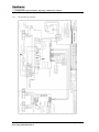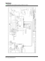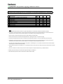
1
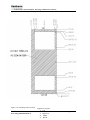
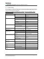
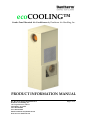
ecoCOOLING™ Combo Panel Mounted Air Conditioners by Dantherm Air Handling, Inc. PRODUCT INFORMATION MANUAL Doc Ref: EcoCooling IOM Manual RevA Dantherm Air Handling, Inc 110 Corporate Drive, Suite K Spartanburg, SC 29303 Tel # 864 595 9800 Fax # 864 595 9810 Email [email protected] Web Site www.dantherm.com Page 1 of 14 ecoCOOLING Combo Installation, Operating & Maintenance Manual Contents 1 GENERAL SAFETY & WARNING INSTRUCTIONS ................................................................... 3 2 UNPACKING, HANDLING & INITIAL INSPECTION.................................................................. 3 3 INSTALLATION ............................................................................................................................... 3 3.1 3.2 4 DESIGN DATA .................................................................................................................................. 6 4.1 4.2 5 MOUNTING OF UNIT TO ENCLOSURE ............................................................................................... 3 UNIT OPERATION .......................................................................................................................... 5 GENERAL PERFORMANCE DATA ..................................................................................................... 6 SUMMARY OF BASIC CONTROLS: ................................................................................................... 6 MAINTENANCE ............................................................................................................................... 8 5.1 TROUBLE SHOOTING ..................................................................................................................... 8 5.2 EVAPORATOR AND CONDENSER COIL CLEANING ............................................................................ 9 5.3 COMPRESSOR & REFRIGERANT SYSTEM ......................................................................................... 9 5.4 BLOWERS ..................................................................................................................................... 9 5.5 FILTERS ........................................................................................................................................ 9 5.6 ELECTRICAL SCHEMATICS ............................................................................................................10 5.6.1 8K 230V Wiring Schematic..................................................................................................10 5.6.2 6K & 4K 230V Wiring Schematic ........................................................................................11 5.7 PREVENTATIVE MAINTENANCE SCHEDULE ....................................................................................12 6 WARRANTY ....................................................................................................................................13 7 RETURN MATERIAL AUTHORIZATION PROCEDURE ..........................................................14 Doc Ref: EcoCooling IOM Manual RevA Page 2 of 14 ecoCOOLING Combo Installation, Operating & Maintenance Manual 1 GENERAL SAFETY & WARNING INSTRUCTIONS Certain parts of electrical systems are inevitably live or have a high operating temperatures. Observe caution at all times. Failure to observe these conditions and installation instructions can cause injury and damage. The system is to be installed and maintained only by trained and qualified personnel. Do not apply power until all ground connections have been made. The unit is fitted with pressed and folded metal parts, which could have sheared metal edges. Be cautious handling the unit, especially when working in poorly accessible places. Check that no tools, test equipment, torches etc. have been left in or on the equipment on completion of work. Ensure the cover(s) and all mounting hardware is firmly secured before leaving installation. All cable and connectors must conform to UL standards. When servicing the unit, do not remove the cover(s) for 5 minutes after switching the unit off to allow pipe work (compressor discharge) to cool. UNPACKING, HANDLING & INITIAL INSPECTION 2 The air conditioner should be inspected on initial delivery and any damage to packaging noted. The unit should be maintained in the upright position at all times. Special consideration should be given to correctness of; external packing damage or abrasion, loose components, surface marks and oil leakage. Any damage should be added to the freight bill and immediately notify the freight company for filing a freight claim. All packaging materials should be retained for inspection. Under no circumstances must the unit be inverted, as the oil will drain from the compressor into the refrigerant piping system. Do not attempt to operate the unit if it appears to be damaged from being dropped or if it is in the horizontal position (on it’s side, back or front). 3 INSTALLATION 3.1 Mounting of unit to enclosure The enclosure shall be checked for correctness of cutouts, mounting holes and electrical supply. See Figure 3.1A Apply gasket to the back of the units mounting surface. See Figure 3.1B for mounting gasket location. Utilize an appropriate and safe lifting device. Mount the Air Conditioner to the cabinet using hardware supplied with unit in ship loose kit. For units equipped with ¼-20 inserts, the maximum torque is 130 in-lbs with a recommended assembly torque of 75 in-lbs. Connect the Air Conditioning Unit power lead to the mains supply located in the cabinet/enclosure. Refer to the product label on the bottom right hand side panel of the unit for the proper voltage/amp requirement. Make sure a properly grounded power supply is used. All installations are to be completed in accordance with local NEC codes and guidelines. The electrical circuit should be protected by a slow blow breaker or fuse. Refer to section 4.1 in this manual for fuse/breaker rating. Check settings for heat and cool temperatures on display on Control Board. And adjust if necessary (See section 4.2 for location). Standard factory settings are Cool = 30oC, Heat = 5oC. Settings may differ per customer requirement. The Air Conditioning Unit is supplied with a condensate drain hose in the ship loose kit. Secure the hose to the drain nipple on the bottom of the unit and route away to suitable position/location. Doc Ref: EcoCooling IOM Manual RevA Page 3 of 14 ecoCOOLING Combo Installation, Operating & Maintenance Manual Figure 3.1A: Cut Out Template ~ Units are in millimeters Figure 3.1B: Mounting Gasket Location Doc Ref: EcoCooling IOM Manual RevA Application of gasket: 1) Top 2) Left Side 3) Right Side 4) Middle 5) Bottom Page 4 of 14 ecoCOOLING Combo Installation, Operating & Maintenance Manual Top Middle Left Right Mounting Hooks Bottom 3.2 Unit Operation Turn AC and DC Mains power on to unit, evaporator fan (internal circuit) should run immediately. Check for the following: Airflow through evaporator coil Abnormal vibration . Doc Ref: EcoCooling IOM Manual RevA Page 5 of 14 ecoCOOLING Combo Installation, Operating & Maintenance Manual 4 Design Data 4.1 General performance Data Model # 4K Combo 6K Combo 8K Combo BTU/ h ** 4,000 Watts Removal ** 1171 6,000 1757 8,000 2343 Voltage (Air Cond.) Voltage (HEX) Hz Ph Breaker Size (AC) Breaker Size (DC) Approx. Weight (lbs / kg) 230V AC 48V DC 50/60 1 15 Amp 7.0 152 / 69 ** Rating capacity shown based on 131F return air temperature to cabinet in 131F ambient conditions at nominal voltage and unimpeded resistance to air flow. 4.2 Summary of Basic Controls: One Important Note: In order for air to air heat exchangers to cool the internal cabinet air, the ambient air must be at a lower temperature than the internal cabinet return temperature. All of these temperatures are monitored by the internal control boards located inside the ecoCOOLING unit. With the combo mode of operation, the air conditioner control board (USACG-6) operates secondary to the heat exchanger control board (USHX2) which is the master control board. The factory setting for the heat exchanger to operate alone is up to 35 Deg C internal return temperature. Once the internal cabinet temperature reaches approx. 36 Deg C, the air conditioner will come on. As long as the ambient is lower than 35 Deg C, the heat exchanger and air conditioner will operate at the same time. Once the ambient is approx. 36 Deg C and an internal temperature is 36 Deg C or higher, the heat exchanger will turn off. At this point the AC is operating on its own. The AC will continue to operate alone until the ambient is lower than the internal temperature, and the internal temperature is below 35 Deg C. Access control boards by removing (10) M4x12 torx with pin screws from top front cover. Doc Ref: EcoCooling IOM Manual RevA Page 6 of 14 ecoCOOLING Combo Installation, Operating & Maintenance Manual Air Conditioner Control Board (USACG-6) AC Power 230V / 115V AC Switch Compressor Relay Compressor Current Sensor Digital Display Right Button Left Button Alarm Interconnect Heat Exchanger Control Board (USHX2) DC Power Internal Fan Ambient / Internal Temp Sensors Interconnect External Fan Alarm Test Button Doc Ref: EcoCooling IOM Manual RevA Page 7 of 14 ecoCOOLING Combo Installation, Operating & Maintenance Manual 5 5.1 MAINTENANCE Trouble Shooting The air conditioners are designed for trouble free life as long as the ambient filter (if applicable) is maintained in a clean condition. To aid in service definition the service personnel can initially identify probable cause by referring to the following trouble shooting chart. If in doubt contact Dantherm Air Handling Inc. for assistance. Always have the Model #, Serial # available before you call. Problem Unit not running Unit not cooling sufficiently Ice on evaporator coil Condensate draining continuously Excessive vibration Missing Compressor Current (F=01) High Pressure Alarm (F=02) Low Pressure Alarm after start (F=03) Low Pressure Alarm before start (F=04) High Temperature Alarm (F=05) Low Temperature Alarm (F=06) Faulty Temperature Sensor (F=07) Potential Cause No Power Fuse Blown on Control Board Faulty control components Filter (if applicable) clogged Blocked evaporator or condenser coil Evaporator or condenser blower not operating Loss of refrigerant or oil leaks Insufficient capacity Insufficient heat load or unit oversized for application Failed evaporator blower Enclosure not properly sealed Solution Check power source and electrical connections Replace with fuse Carry out self test Clean or replace filter Clean coil Replace motor, capacitor or entire assembly Locate and repair leak. Replace charge Contact Dantherm Air Handling, Inc. Contact Dantherm Air Handling, Inc. Replace evaporator blower motor or assembly Check and seal all openings Loose compressor, fans or tubing Faulty compressor Broken current sensor Wire detached or improperly installed Faulty condensor fan or wiring loose Faulty condensor fan capacitor or wiring loose Faulty condensor fan switch or high pressure switch Slow leak in system Locate and correct Replace compressor Replace Control Board Secure wiring or install wiring properly according to diagram Replace fan or check wiring to fan No refrigerant in system (Large leak) Low charge in system Unit undersized for application Locate and repair leak. Replace charge Insufficient heat load or unit oversized for application Sensor not connected Faulty sensor Contact Dantherm Air Handling, Inc. Doc Ref: EcoCooling IOM Manual RevA Replace capacitor or check wiring to capacitor Replace appropriate switch Locate and repair leak. Replace charge Locate and repair leak. Replace charge Contact Dantherm Air Handling, Inc. Reconnect sensor Replace sensor Page 8 of 14 ecoCOOLING Combo Installation, Operating & Maintenance Manual 5.2 Evaporator and Condenser Coil Cleaning Periodically the coils should be cleaned. No fixed period for cleaning can be provided due to the varying environments in which the air conditioner may be installed. However once the coils become visibly coated with dust it is recommended that they be cleaned with a brush or compressed air. Both sides of the coils should be inspected regularly. 5.3 Compressor & Refrigerant System The compressor is a hermetically sealed and factory lubricated unit and therefore requires no maintenance. If the compressor fails it is recommended that the unit be returned to Dantherm HMS, Inc. for servicing. In the event that the unit cannot be returned it is possible, using suitably qualified personnel, to repair the unit in the field. However this voids product warranty. If the refrigerant charge is lost the means of leakage should be established and repaired by a reputable refrigeration repair company. Ports are provided for checking suction and discharge pressures and recharging if required. The type of refrigerant and charge amount is detailed on the product label attached to the unit. Note: Under no circumstance must the access port covers be removed, adjusted, or tampered with other than by a certified technician. 5.4 Blowers Condenser and evaporator blowers require no maintenance other then periodic inspection. In the event of dust build-up clean the blowers. 5.5 Filters If applicable, the external filter shall be checked on a regular basis dependent on environmental conditions and replaced as necessary. Doc Ref: EcoCooling IOM Manual RevA Page 9 of 14 ecoCOOLING Combo Installation, Operating & Maintenance Manual 5.6 Electrical Schematics 5.6.1 8K 230V Wiring Schematic Doc Ref: EcoCooling IOM Manual RevA Page 10 of 14 ecoCOOLING Combo Installation, Operating & Maintenance Manual 5.6.2 6K & 4K 230V Wiring Schematic Doc Ref: EcoCooling IOM Manual RevA Page 11 of 14 ecoCOOLING Combo Installation, Operating & Maintenance Manual 5.7 Preventative Maintenance Schedule Dantherm Air Handling, Inc.Air Conditioner Preventative Maintenance Schedule 1 2 3 4 5 6 7 8 9 10 Maintenance Item Check enclosure air or ambient air filter (If applicable) Condenser coil cleaning Rotating component current check Functional Check Fan/Blower Inspection Evaporator coil cleaning Cabinet cleaning & Corrosion Check Condensate drains Refrigerant charge Lubrication * Can be extended to 6 months after initial visits if no cleaning is required. 3 or 6 6 Monthly Monthly X* X* X X X Yearly 5 Yearly X X X X X Notes: 1 The internal/external filter shall be checked on a regular basis dependent on environmental conditions and replaced as necessary. 2 Periodically the coils should be cleaned. Once the coils become visibly coated with dust it is recommended that they be cleaned with a brush or compressed air. Both sides of the coils should be inspected. The condenser coil may be washed with a commerc 3 Check run amps on rotating components and record to enable assesment of potential failure 4 Perform Self Test Function in acordance with Operation Manual. Complete general check of component mounting. 5 Condenser and evaporator blowers require no maintenance other then periodic inspection. In the event of dust build-up clean the blowers. 6 Periodically the coils should be cleaned. Once the coils become visibly coated with dust it is recommended that they be cleaned with a brush or compressed air. Both sides of the coils should be inspected. The condenser coil may be washed with a commerc 7 The cabinet can be cleaned with a sponge and warm, soapy water or a mild detergent. Do not use bleach, abrasive chemicals or harmful solvents. Check for signs of corrosion and treat as necessary. 8 Check the drain and drain tube for obstructions. If a commercial drain solvent is used, flush out the drain pan and system with fresh water to prevent corrosion. 9 Under no circumstance must the access port covers be removed, adjusted, or tampered with other than by a certified technician. 10 Rotating component bearings must be lubricated using SAE20 weight non detergent oil. 11 All maintenance inspections must be recorded with time, date & details of activity. Doc Ref: EcoCooling IOM Manual RevA Page 12 of 14 ecoCOOLING Combo Installation, Operating & Maintenance Manual 6 Warranty DANTHERM AIR HANDLING, INC., HEAT EXCHANGER AND AIR CONDITIONING UNITS LIMITED WARRANTY DANTHERM AIR HANDLING, INC.’s (“DANTHERM”) limited warranty extends to the original purchaser only of any DANTHERM Pinnacle heat exchanger and Classic air conditioning unit, and to no other person or entity. DANTHERM warrants that such DANTHERM products will be free from defects in materials and workmanship in normal use for a period of twelve (12) months from the date of the original purchase. Should any part of your DANTHERM product fail because of a manufacturing defect within such twelve (12) month period, DANTHERM terms are set out below: PRODUCT WARRANTY WARRANTY PERIOD* CLASSIC (A/C) 12 months PARTS SUPPLY ONLY PARTS & LABOR Supply part freight prepaid by Dantherm. Return of defective part pre-paid by customer Return of item freight pre-paid by customer Supply of item freight pre-paid by Dantherm. PINNACLE (HEX) 12 months PARTS SUPPLY ONLY PARTS & LABOR Supply part freight prepaid by Dantherm. Return of defective part pre-paid by customer Return freight pre-paid by customer Supply freight pre-paid by Dantherm. ** * SHIPMENT LIABILITY PRODUCT IN FIELD WARRANTY** RETURN TO BASE WARRANTY IN FIELD RETURN TO BASE Using Dantherm nominated service contractors – warranty on product continues Using Dantherm non-approved service contractors – warranty on product becomes void Warranty period starts from date of dispatch – warranty of replacement parts shall only apply for the remainder of the warranty period of the original product. Any transportation, related service labor, diagnosis calls, filters, driers, and refrigerant are not included. In the event all related service labor is performed by DANTHERM nominated service contractors, the replacement part shall be warranted by DANTHERM for the remainder of the warranty period of the original product. This warranty does not cover damages or repairs caused by improper installation, misuse of the product, negligent servicing, improper applications, unauthorized modifications, improper electrical supply, failure to follow manufacturer’s instructions and rating plate information, accidents, natural disasters, damage in transportation, lack of normal preventive maintenance, or other events beyond DANTHERM’s control. This warranty is also subject to the following operating conditions: 1) voltage variation not greater than 10%, 2) frequency variation not greater than 3Hz from nameplate rating, 3) cooling load is not greater than product label under rated conditions 4) unit is not restarted for a period of five minutes after accidental or intentional shut-off, 5) operation is not subject to abnormal conditions or customer, user misapplication, 6) customer or user does not modify, abuse, or neglect the product, 7) refrigerant specified on nameplate is only refrigerant used, and 8) customer or user complies with all other installation, maintenance, and operating instructions. Cost of repair or replacement of consumable parts is not covered under the terms of this warranty. THIS WARRANTY CONSTITUTES THE EXCLUSIVE REMEDY OF ANY PURCHASER OF A DANTHERM PINNACLE HEAT EXCHANGER AND CLASSIC AIR CONDITIONING UNIT AND IS IN LIEU OF ALL OTHER ARRANTIES, EXPRESS OR IMPLIED, INCLUDING, WITHOUT LIMITATION, ANY IMPLIED WARRANTIES OF MERCHANTABILITY, FITNESS FOR USE, OR FOR A PARTICULAR PURPOSE. IN NO EVENT SHALL ANY IMPLIED WARRANTIES OF MERCHANTABILITY, FITNESS FOR USE, OR FOR A PARTICULAR PURPOSE EXCEED THE TERMS OF THE APPLICABLE WARRANTY STATED ABOVE, AND DANTHERM SHALL HAVE NO OTHER OBLIGATION OR LIABILITY, EXPRESS OR IMPLIED. IN NO EVENT SHALL DANTHERM BE LIABLE FOR ANY INCIDENTAL OR CONSEQUENTIAL DAMAGES. THIS WARRANTY GIVES YOU SPECIFIC LEGAL RIGHTS, AND YOU MAY ALSO HAVE OTHER RIGHTS WHICH VARY FROM STATE TO STATE. SOME STATES DO NOT ALLOW LIMITATIONS OR EXCLUSIONS, SO THE ABOVE LIMITATIONS AND EXCLUSIONS MAY NOT APPLY TO YOU. Doc Ref: EcoCooling IOM Manual RevA Page 13 of 14 ecoCOOLING Combo Installation, Operating & Maintenance Manual 7 RETURN MATERIAL AUTHORIZATION PROCEDURE In the unlikely event of unit failure the following return procedure shall be adopted. All product returns require a Return Material Authorization number regardless of reason. The customer is required to contact the Quality Department at Dantherm Inc. in Spartanburg, SC at (864) 595 9800 to obtain an RMA number. The following information must be provided prior to a RMA number being issued: Dantherm Air Handling, Inc. part number(s) of product to be returned. Dantherm Air Handling, Inc. serial number(s) of product to be returned. Number of units requested to be returned. Reason for return. Contact name, phone and fax number. Date of product receipt. Invoice number and purchase order number covering the unit(s). The customer is responsible for suitably packaging the unit(s) securely, ideally in the original packaging, marking all cartons with the RMA number and shipping them prepaid to the designated site specified by Dantherm Air Handling, Inc. IN NO EVENT SHALL DANTHERM INC. ACCEPT ANY SHIPMENT WHICH DOES NOT COMPLY WITH THE ABOVE PROCEDURES. REMOVE THE EMERGENCY HOSE AND ADAPTER FROM THE BOTTOM OF THE UNITS PRIOR TO DISMANTLING THE AIR CONDITIONER AND RESTING IT ON THE GROUND. Doc Ref: EcoCooling IOM Manual RevA Page 14 of 14