1
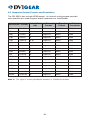
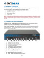
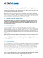
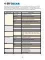
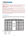
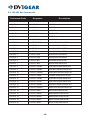
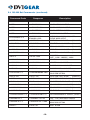
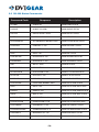
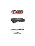
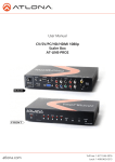
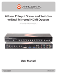
User Guide
Video-PC to HDMI Converter / Scaler
DVI-3551a
Table of Contents
SectionPage
Product Safety . . . . . . . . . . . . . . . . . . . . . . . . . . . . . . . . . . . . 1
Product LIABILITY. . . . . . . . . . . . . . . . . . . . . . . . . . . . . . . . . . . 1
1.Introduction. . . . . . . . . . . . . . . . . . . . . . . . . . . . . . . . . . . 2
2.Specifications. . . . . . . . . . . . . . . . . . . . . . . . . . . . . . . . . . 3
3. PACKAGE CONTENTS. . . . . . . . . . . . . . . . . . . . . . . . . . . . . . 6
4. CONNECTING THE HARDWARE. . . . . . . . . . . . . . . . . . . . . . 6
5.Operating the Unit. . . . . . . . . . . . . . . . . . . . . . . . . . . . . . 8
6.Troubleshooting. . . . . . . . . . . . . . . . . . . . . . . . . . . . . . 15
7.Limited Warranty. . . . . . . . . . . . . . . . . . . . . . . . . . . . . . 16
8.Regulatory Compliance. . . . . . . . . . . . . . . . . . . . . . . 16
WARNING – Product Safety
1. Do not dismantle the product housing or modify the printed circuit board
module as this may result in electrical shock or burn.
2. Do not attempt to service this product yourself as opening or removing the
product housing may expose you to dangerous voltages or other hazards.
Refer all servicing to qualified service personnel.
3. Keep this product away from liquids. Spills into the product housing may
result in fire, electrical shock, or equipment damage. If liquid spills into the
housing, unplug the product immediately. Have the product checked by a
qualified service engineer before using it again.
4. Place the product in an even and stable location. If the product falls or is
dropped, it may cause an injury and/or malfunction.
5. Avoid exposing the product to extreme temperatures or to high humidity
levels as this may result in damage to the product.
6. Only use the supplied External AC Power Adapter. The use of other power
adapters may cause this product to fail or may cause a fire.
7. Do not twist or exert excessive force on the ends of the cables connected to
this product as this may cause it to malfunction.
Product Liability
Every effort has been made to ensure that this product is free of defects.
DVIGear cannot be held liable for the use of this product or for any direct or
indirect consequential damages arising from its use. It is the responsibility of
the users of this product to check that it is suitable for their requirements and
that it is installed correctly.
All rights are reserved. No parts of this manual may be reproduced or transmitted
by any form or means electronic or mechanical, including photocopying,
recording or by any information storage or retrieval system without the written
consent of DVIGear.
DVIGear reserves the right to revise any of its hardware and software following
its policy to modify and/or improve its products where necessary or desirable.
This statement does not affect the legal rights of the user in any way. All
third-party trademarks and copyrights are recognized. The DVIGear logo is a
registered trademark of DVIGear, Inc. HDMI™ is a registered trademark of
HDMI LLC. All other trademarks are the property of their respective holders.
-1-
1.0INTRODUCTION
The model DVI-3551a is a professional quality Switcher / Converter / Scaler
with an HDMI output. The unit offers switchable input connections that
accommodate a wide array of input signal formats, including: HDMI, DVI
(via DVI-to-HDMI adapter), RGB Analog via an HD15-pin connector, Analog
Component Video (both YPbPr and YUV formats), S-Video, and Composite
Video. All video inputs include stereo audio follow, which are digitally
embedded in the HDMI output signal. A separate S/PDIF Coaxial Digital
Audio input and output are also provided. User adjustable audio delay can
be introduced to ensure proper audio lip-sync. The DVI-3551a unit features a
high-performance scaling engine that allows user-selection of a wide range of
PC and HDTV output resolutions up to 1920x1200 and 1080p/60.
Our professional digital distribution products have been serving the industry
for over ten (10) years. DVIGear offers a full line of high quality Digital Matrix
Routers, Switchers, Splitters, Video Scalers, Up/Down/Cross Converters,
Format Converters, Analog-Digital Converters, as well as a wide range of long
reach Digital Cables, Extenders, and Optical Transmission systems.
1.1Features
The DVI-3551a Video-PC to HDMI Converter/Scaler offers several advanced
features:
• Output Resolutions up to 1080p and WUXGA
• HDMI/DVI, RGB, YPbPr, YUV, YC, and CV Inputs
• Stereo Audio inputs with Audio Follow switching
• Adjustable Audio Delay for Lip-Sync Correction
• HDMI I/O is fully HDCP Compliant
• Infrared Remote Control
• RS232 control of all switching and display functions
• 3D Motion Adaptive De-Interlacing
• 3:2 Pull-Down with 2:2 Pull-Down Recovery
• Digital Noise Reduction
• AC Power Adapter with locking plug for add security
• Optional Rack Mount Kit
-2-
2.0SPECIFICATIONS
Input Connections
HDMI or DVI
Analog RGB
Analog Component Video
S-Video
Composite Video
Digital Audio (S/PDIF)
Stereo Audio
Input Formats
HDMI / DVI
Analog RGB
Analog Component Video
Composite Video & S-Video (Y/C)
Output Formats
HDMI
HDMI Output Resolutions
HDMI Embedded Audio
Digital Coaxial Audio (S/PDIF)
Audio Delay Adjustment
Device Control
Front Panel
IR Remote Control
RS232 Control
Scaling Engine
Phase Lock Loops
De-Interlacing
Pull-Down
Mechanical
Size (H x W x D)
Weight (net)
Environmental
Operating Temperature
Storage Temperature
Operating / Storage Humidity
Power Requirements
AC Power Adapter
Regulatory Approvals
Converter/Scaler Unit
AC Power Adapter
Accessories
Included Accessories
Optional Accessories
1x HDMI female connector, DVI using DVI-8511b Adapter (not included)
1x HD15-pin VGA female connector
3x RCA female connectors
1x 4-pin Mini-DIN female connector
1x RCA female connector
1x RCA female connector
6x RCA and 2x PC Audio (3.5mm)
HDMI v1.2 / HDCP 1.1 compliant (see table on page 4)
Up to 1920x1200@60 Hz, 1600x1200@60Hz
YPbPr / YCbCr up to 1080p
NTSC / PAL formats
1x HDMI female connector, HDMI v1.2 compliant
Up to 1080p@60Hz and 1920x1200@60 Hz (see table on page 5)
Digital audio per HDMI specification
1x RCA female connector
OFF, 40 ms, 110 ms, 150 ms
10x Buttons with On-Screen Display navigation
IR Remote Control with On-Screen Display navigation
See tables on pages 11-14
8-bit, Triple Analog to Digital Converter
3D Motion Adaptive De-Interlacing with 3D Noise Reduction
3:2 with 2:2 recovery
1.9” x 8.5” x 6.1”
2.2 lbs. (1.0 kg)
(47.2 mm x 215.2 mm x 154.7 mm)
+32° to +122°F
(0° to +50°C)
+14° to +158°F
(-10° to +70°C)
10% to 85%, Non-Condensing
Input: 100-240VAC @50/60Hz
Output: 5VDC @2.0A
FCC, CE, RoHS
FCC, CE, UL, CUL, PSE, GS, RoHS
IR Remote Control Unit, AC Power Adapter, User Guide
International AC Power Adapter (USA, Euro, UK, Australia)
DVI-5300-RM Rack Mount Kit
-3-
2.1 Supported Input Formats and Resolutions
The DVI-3551a accepts HDMI, DVI, Analog RGB, Analog Component Video,
S-Video (Y/C), and Composite Video inputs via rear-panel connectors. The
resolutions and formats supported by these inputs are as follows:
Resolution / Format
Vertical Rate
(Hz)
NTSC/PAL
60 NTSC, 50 PAL
SDTV
Scan
Format
Interlaced
Signal Format
Composite Video
Input
Connector
RCA
NTSC/PAL
SDTV
60 NTSC, 50 PAL
Interlaced
S-Video (Y/C)
4-pin mini-DIN
480i
720x480
60
Interlaced
YUV NTSC
RCA, HDMI (1)
576i
720x576
50
Interlaced
YUV PAL
RCA, HDMI (1)
480p
720x480
60
Progressive
YPbPr / RGBHV (2)
HD15, HDMI, RCA
576p
720x576
50
Progressive
YPbPr / RGBHV (2)
HD15, HDMI, RCA
720p
1280x720
50, 60
Progressive
YPbPr / RGBHV (2)
HD15, HDMI, RCA
1080i
1920x1080
50, 60
Interlaced
YPbPr / RGBHV (2)
HDMI, RCA
1080p
1920x1080
50, 60
Progressive
YPbPr / RGBHV (2)
HD15, HDMI, RCA
VGA
640x480
60, 72, 75, 85
Progressive
RGBHV
HD15, HDMI
SVGA
800x600
56, 60, 72, 75, 85
Progressive
RGBHV
HD15, HDMI
XGA
1024x768
60, 70, 75, 85
Progressive
RGBHV
HD15, HDMI
SXGA
1280x1024
60, 75, 85
Progressive
RGBHV
HD15, HDMI
UXGA
1600x1200
60
Progressive
RGBHV
HD15, HDMI
WXGA
1280x800
60
Progressive
RGBHV
HD15, HDMI
WSXGA
1680x1050
60
Progressive
RGBHV
HD15, HDMI
WUXGA
1920x1200
60
Progressive
RGBHV
HD15, HDMI
Note 1: This signal is actually 480i@30Hz doubled, or 576i@25Hz doubled.
Note 2: Analog YPbPr input is only available via the 3-RCA connectors, not via
the HD15-pin Connector.
-4-
2.2 Supported Output Formats and Resolutions
The DVI-3551a has a single HDMI output. An internal scaling engine provides
user selection of a wide range of output resolutions as listed below:
Resolution / Format
Vertical Rate
(Hz)
Scan
Format
Signal
Format
Output
Connector
480i
720x480
60
Interlaced
YUV NTSC
HDMI (1)
576i
720x576
50
Interlaced
YUV PAL
HDMI (1)
480p
720x480
60
Progressive
RGBHV
HDMI
576p
720x576
50
Progressive
RGBHV
HDMI
720p
1280x720
50, 60
Progressive
RGBHV
HDMI
1080i
1920x1080
50, 60
Interlaced
RGBHV
HDMI
1080p
1920x1080
50, 60
Progressive
RGBHV
HDMI
VGA
640x480
60
Progressive
RGBHV
HDMI
SVGA
800x600
60
Progressive
RGBHV
HDMI
XGA
1024x768
60
Progressive
RGBHV
HDMI
SXGA
1280x1024
60
Progressive
RGBHV
HDMI
SXGA+
1400x1050
60
Progressive
RGBHV
HDMI
UXGA
1600x1200
60
Progressive
RGBHV
HDMI
WXGA
1280x800
60
Progressive
RGBHV
HDMI
WXGA+
1440x900
60
Progressive
RGBHV
HDMI
WSXGA
1680x1050
60
Progressive
RGBHV
HDMI
WUXGA
1920x1200
60
Progressive
RGBHV
HDMI
Note 1: This signal is actually 480i@30Hz doubled, or 576i@25Hz doubled.
-5-
3.0 PACKAGE CONTENTS
Before attempting to use this unit, please check the packaging and make certain
the following items are contained in the shipping carton:
•
•
•
•
DVI-3551a Video-PC to HDMI Converter / Scaler
AC Power Adapter
IR Remote Control
User Guide
Note: Please retain the original packing material should the need ever arise to return the
unit. If you find any items are missing, contact your reseller or DVIGear immediately. Please
have the Model Number, Serial Number, and Invoice Number available for reference when
you call.
4.0 CONNECTING THE HARDWARE
Please study the images below to become familiar with the locations of the
controls, signal inputs, signal output, and the power input.
Front Panel Controls: The front panel has several push buttons to manually
control the unit. The numbers below the product photo relate to the control
directly above the number.
1
1
2
3
4
5
6
7
8
9
10
11
2
3
4
5
6
7
Power ON / OFF Switch
Infrared Receiver Sensor
Composite Video Input Select
S-Video Input Select
Component Video Input Select
PC (RGB Analog) Input Select
HDMI / DVI Input Select
On-Screen Display Menu Select
Selected Menu Item Decrease (-)
Selected Menu Item Increase (+)
Enter, Select (or Memorize) Menu Item
-6-
8
9
10
11
Rear Panel Connectors: The rear panel has the connectors required to
interface the unit to all Input / Output devices and the External AC Power
Adapter. The numbers above and below the drawing relate to the connector
directly above or below the number. Refer to the corresponding number and
functional description below.
1
9
2
3
10
4
5
11
6
12
7
8
13
14
15
1
S/PDIF Audio Output (for use with external audio system)
2
3.5mm AUX Audio Input (for use when DVI signal is applied to the
HDMI input)
3
RS-232 Control Port
4
3.5mm PC Audio Input (for use with PC audio output)
5
Stereo Audio Input for Component Video Input (2x RCA Connectors)
6
S/PDIF Digital Audio Input
7
Stereo Audio Input for Composite Video Input (2x RCA Connectors)
8
Composite Video Input (RCA Connector)
9
HDMI Video Output
10 HDMI or DVI Video Input
11 PC / RGB Analog Input (HD15-pin connector)
12 Component Video Inputs (3x RCA Connectors)
13 Stereo Audio Input for S-Video Input (2x RCA Connectors)
14 S-Video Input (4-pin mini-DIN)
15 +5 VDC Input (connects to external AC Power Adapter)
Connect the supplied AC Power Adapter to the DVI-3551a. Use only the
furnished power adapter to avoid the possibility of equipment damage. Next,
connect the appropriate cables to the Input(s) and Output and power ON the
source and destination devices.
Plug the AC Power Adapter into the unit and into an AC wall outlet. The unit will
automatically power ON. Verify that the LED above the switch lights up indicating
-7-
that power has been applied to the unit. Press the Power button to turn the
unit OFF / ON again as needed. In the event of a power outage, this unit will
automatically power ON and restore the last used settings as soon as power is
reapplied to the unit.
Note: Proper operation of this product depends on the use of the high quality cables.
DVIGear’s Super High Resolution (SHR™) cables provide low loss, low jitter, high bandwidth
signal handling and are recommended for use with this product.
5.0OPERATING THE UNIT
The DVI-3551a Convert/Scaler can be operated from either the front panel
controls, or via the included Infrared Remote Control unit.
Since Infrared is the control method used by the majority of users, please take
the time to familiarize yourself with the location and function of the various
control buttons on the Controller.
Select PC Input
Toggle through
the Inputs
Select YPbPr
Input
Select Output
Resolution
Exit Menu
INPUT
POWER
Power On/Off
HD
PC
HDMI/DVI
VGA
SVGA
XGA
SXGA
UXGA
1080i
480p
720p
1080p
Select HDMI Input
EXIT
MENU
OK
Reset to Factory
Default Settings
AUTO
ADJUST
RESET
Select OSD Menu
Navigate Menus
and Adjustments
Select Auto-Adjust
Function
CR-27*A
Note: Please use the OSD menu for resolutions not directly accessible from the IR remote.
-8-
5.1 Manual Control
Referring to the front panel image on page 6, the Power and Input selection
switches have LEDs above them to indicate that the power is “ON” and/or an
Input selection has been made. Simply press the Power switch and then press
the appropriate input selection push button.
To the right of the Video Input selection area are the control push buttons for
MENU select, Increase (+), Decrease (-), and ENTER. Pressing the MENU push
button causes the OSD (On-Screen Display) menu to appear. See Section 5.2
below for a detailed description of the OSD menu system.
5.2 Using the On-Screen Display Menus
Regardless of whether you operate the Converter/Scaler from the front panel
or using the IR Remote Controller, it is necessary to become familiar with the
On-Screen Display (OSD) menu system in order to take full advantage of the
capabilities of this product.
5.2.1 Menu Navigation
Press the “MENU” button to display the OSD Menu. Use the front panel
controls marked “+” and “-“ to navigate to the desired function and then press
the ENTER button to make the selection. Next, use the “+” and “-” buttons to
make the adjustment and press the ENTER button to save your selection. To
leave the OSD Menu, highlight the word “Exit” in any menu and then press the
ENTER button.
When using the IR remote controller, press the MENU key to activate the OSD
Menu. Use the arrow buttons to navigate to the desired menu selection then
press the “OK” button. Next, use the arrow buttons to make the adjustment
then press the “OK” button to save the setting. Press the EXIT button to escape
from the OSD Menu.
5.2.2 Menu Structure
The Converter/Scaler’s OSD Menu is organized in two levels. The first level allows
selection of the main menu functions (Video, Color, Output, OSD Characteristics,
Audio, Information, and Exit). The second level allows specific adjustments or
operational selections to be made. The table below and on the following page
shows the relationship of the high level and secondary menu functions that are
used to make up the OSD. To use these functions, proceed as follows:
Display the OSD Menu and use the Decrease (-) push button to move upwards
and the Increase (+) push button to move downwards through the menu list.
Use the ENTER push button to select the desired high-level menu item (Video,
Color, Output, OSD Characteristics, Audio, Information, or Exit).
-9-
Navigate to the specific parameter you wish to adjust and then press the ENTER
push button to make the selection. Use the Decrease (-) and Increase (+) push
buttons to select a different value for the parameter (e.g., change output resolution
or change brightness). Use the Exit selection to leave the OSD Menu.
High Level
VIDEO
COLOR
OUTPUT
Exit
User / Standard / Vivid / Movie
Contrast
0-100 Relative Contrast Adjustment
Brightness
0-100 Relative Brightness Adjustment
Hue
0-100 Relative Hue Adjustment
Saturation
0-100 Relative Color Level Adjustment
Sharpness
0-100 Relative Picture Sharpness Adjustment
Scale
Overscan / Underscan / Letterbox / Panscan / Full
Noise Reduction
Low / Middle / High / Off
Exit
Return to High Level Menu
Color Tone
User / Normal / Warm / Cool
Red
0-100 Relative Red Color Level
Green
0-100 Relative Green Color Level
Blue
0-100 Relative Blue Color Level
Exit
Return to High Level Menu
VGA, SVGA , XGA, SXGA, UXGA, SXGA+, 480I, 480P,
720P60, 1080I60, 1080P60, 576I, 576P, 720P50,
1080I50, 1080P50, NATIVE, WXGA, WSXGA, WUXGA,
WXGA+
(2)
(3)
INFORMATION
Adjustment
Picture Mode
(1)
OSD CONTROL
AUDIO
Secondary
Level
(4)
Exit
Return to High Level Menu
H Position
0-100 Relative L-R Position
V Position
0-100 Relative U-D Position
Timer
0-100 Relative OSD Show Time (Sec)
Transparency
0-100 Relative OSD Text Transparency
Exit
Return to High Level Menu
Source
HDMI / L-R / Coaxial
Delay
OFF / 40 ms / 110 ms / 150 ms
Sound
ON / Mute
Exit
Return to High Level Menu
Source (Input Interface)
Input (Input Resolution)
Output (Output Resolution)
Version (Firmware Version)
Close the OSD Menu
-10-
OSD Menu Notes:
Note 1: The Output sub-menu provides user-selection of the desired output resolution.
Please be aware that some output resolution settings can cause an apparent malfunction if
the selected resolution is not compatible with the connected display device.
CAUTION: Make certain your display device can reproduce the resolution you select
BEFORE you select it.
Note 2: The OSD sub-menu provides user-selection of the On-Screen Display location
and appearance to suit personal preference. You can change the default settings if you
wish, or simply leave it at the factory setting.
Note 3: Since Video and Audio Lip-Sync can be lost in digital television systems, this unit
provides a secondary menu item called “Delay” under the Audio high level menu selection.
An audio delay can be introduced to restore proper lip-sync. Use this function if you hear
audio before the video portion of the program appears to make the corresponding sound.
Note 4: The Info sub-menu contains technical information. If you have problems with this
unit and require assistance, a technician may ask you to read information from this menu
as part of the troubleshooting process.
5.3RS-232 Protocol
The DVI-3551a is equipped with a RS-232 serial control port. The connection
between the DVI-3551a and PC host controller should be made with an RS-232
modem cable.
Pin-Out of RS-232 Modem Cable
DVI-3551a
Host Controller
PIN
Definition
PIN
Definition
1
NC
1
NC
2
TxD
2
RxD
3
RxD
3
TxD
4
NC
4
NC
5
GND
5
GND
6
NC
6
NC
7
NC
7
NC
8
NC
8
NC
9
NC
9
NC
RS-232 Transmission Format:
Baud Rate: Data Bit: Parity: Stop Bit: 19,200 bps
8 bits
None
1 bit
-11-
5.4RS-232 Set Commands:
Command Code
Response
Description
S POWER 0
> POWER OFF
POWER OFF
S POWER 1
> POWER ON
POWER ON
S SOURCE 0
> SOURCE CV
CV INPUT
S SOURCE 1
> SOURCE SV
SV INPUT
S SOURCE 2
> SOURCE COMP
COMP INPUT
S SOURCE 3
> SOURCE PC
PC INPUT
S SOURCE 4
> SOURCE HDMI
HDMI INPUT
S OUTPUT 0
> OUTPUT NATIVE
NATIVE RESOLUTION OUTPUT
S OUTPUT 1
> OUTPUT VGA
VGA RESOLUTION OUTPUT
S OUTPUT 2
> OUTPUT SVGA
SVGA RESOLUTION OUTPUT
S OUTPUT 3
> OUTPUT XGA
XGA RESOLUTION OUTPUT
S OUTPUT 4
> OUTPUT SXGA
SXGA RESOLUTION OUTPUT
S OUTPUT 5
> OUTPUT UXGA
UXGA RESOLUTION OUTPUT
S OUTPUT 6
> OUTPUT 480I
480I RESOLUTION OUTPUT
S OUTPUT 7
> OUTPUT 480P
480P RESOLUTION OUTPUT
S OUTPUT 8
> OUTPUT 720P60
720P 60HZ RESOLUTION OUTPUT
S OUTPUT 9
> OUTPUT 1080I60
1080I 60HZ RESOLUTION OUTPUT
S OUTPUT 10
> OUTPUT 1080P60
1080P 60HZ RESOLUTION OUTPUT
S OUTPUT 11
> OUTPUT 576I60
576I 60HZ RESOLUTION OUTPUT
S OUTPUT 12
> OUTPUT 576P60
576P 60HZ RESOLUTION OUTPUT
S OUTPUT 13
> OUTPUT 720P50
720P 50HZ RESOLUTION OUTPUT
S OUTPUT 14
> OUTPUT 1080I50
1080I 50HZ RESOLUTION OUTPUT
S OUTPUT 15
> OUTPUT 1080P50
1080P 50HZ RESOLUTION OUTPUT
S OUTPUT 16
> OUTPUT WXGA
WXGA RESOLUTION OUTPUT
S OUTPUT 17
> OUTPUT WSXGA
WSXGA RESOLUTION OUTPUT
S OUTPUT 18
> OUTPUT WUXGA
WUXGA RESOLUTION OUTPUT
S OUTPUT 19
> OUTPUT WXGA+
WXGA+ RESOLUTION OUTPUT
S OUTPUT 20
> OUTPUT SXGA+
SXGA+ RESOLUTION OUTPUT
-12-
5.4RS-232 Set Commands: (continued)
Command Code
Response
Description
S SIZE 0
> SIZE FULL
SCALER FULL OUTPUT
S SIZE 1
> SIZE OVERSCAN
SCALER OVERSCAN OUTPUT
S SIZE 2
> SIZE UNDERSCAN
SCALER UNDERSCAN OUTPUT
S SIZE 3
> SIZE LETTERBOX
SCALER LETTERBOX OUTPUT
S SIZE 4
> SIZE PANSCAN
SCALER PANSCAN OUTPUT
S PICTUREMODE 0~3
> PICTUREMODE
STANDARD~USER
0:STANDARD;1:MOVIE;2:VIVID;3:USER,
PICTURE MODE OUTPUT
S CONTRAST 0~100
> CONTRAST 0~100
CONTRAST 0~100 ADJUST
[Default: 45]
S BRIGHTNESS 0~100
> BRIGHTNESS 0~100
BRIGHTNESS 0~100 ADJUST
[Default: 46]
S HUE 0~100
> HUE 0~100
HUE 0~100 ADJUST
[Default: 50]
S SATURATION 0~100
> SATURATION 0~100
SATURATION 0~100 ADJUST
[Default: 56]
S SHARPNESS 0~100
> SHARPNESS 0~100
SHARPNESS 0~100 ADJUST
[Default: 32]
S NR 0~3
> NR OFF~HIGH
NR CONTROL
0:OFF; 1:LOW; 2:MIDDLE; 3:HIGH
S PCHPOSITION 0~100
> PCHPOSITION 0~100
H POSITION 0~100 ADJUST
S PCVPOSITION 0~100
> PCVPOSITION 0~100
V POSITION 0~100 ADJUST
S PCCLOCK 0~100
> PCCLOCK 0~100
PC MODE CLOCK 0~100 ADJUST
S PCPHASE 0~63
> PCPHASE 0~63
PC MODE PHASE 0~63 ADJUST
> COLORTEMP NORMAL~USER
0:NORMAL; 1:WARM; 2:COOL; 3:USER ,
COLOR TEMP SETTING
S COLORTEMP 0~3
S RED 0~100
> RED 0~100
COLOR TEMP "RED" ADJUST
S GREEN 0~100
> GREEN 0~100
COLOR TEMP "GREEN" ADJUST [Default: 47]
S BLUE 0~100
> BLUE 0~100
COLOR TEMP "BLUE" ADJUST
S OSDHPOSITION 0~100
> OSDHPOSITION 0~100
OSD H POSITION 0~100 ADJUST [Default: 50]
S OSDVPOSITION 0~100
> OSDVPOSITION 0~100
OSD V POSITION 0~100 ADJUST [Default: 50]
S OSDTIMEOUT 0~100
> OSDTIMEOUT 0~100
OSD TIMEOUT 0~100 SETTING [Default: 10]
S OSDBACKGROUND 0~8
> OSDBACKGROUND 0~8
OSD OSDBACKGROUND 0~8 ADJUST [Default: 5]
S AUDIOMUTE 0~1
> AUDIOMUTE OFF~ON
0:OFF ; 1:ON , AUDIO MUTE CONTROL
S AUDIODELAY 0~3
> AUDIODELAY OFF~150MS
0:OFF ; 1:40MS ; 2:110MS ; 3:150MS ,
AUDIO DELAY SETTING
S RESET 1
> RESET ON
RESET ACTION
-13-
[Default: 47]
[Default: 47]
5.5RS-232 Status Commands:
Command Code
Response
Description
R POWER
> POWER ON
SHOW POWER STATUS
R SOURCE
> SOURCE CV~HDMI
SHOW SOURCE STATUS
R OUTPUT
> OUTPUT NATIVE~SXGA+
SHOW OUTPUT STATUS
R SIZE
> SIZE FULL~PANSCAN
SHOW SIZE STATUS
R PICTUREMODE
> PICTUREMODE STANDARD~USER
SHOW PICTURE MODE STATUS
R CONTRAST
> CONTRAST 0~100
SHOW CONTRAST STATUS
R BRIGHTNESS
> BRIGHTNESS 0~100
SHOW BRIGHTNESS STATUS
R HUE
> HUE 0~100
SHOW HUE STATUS
R SATURATION
> SATURATION 0~100
SHOW SATURATION STATUS
R SHARPNESS
> SHARPNESS 0~100
SHOW SHARPNESS STATUS
R NR
> NR OFF~HIGH
SHOW NR STATUS
R PCHPOSITION
> PCHPOSITION 0~100
SHOW PC H-POSITION STATUS
R PCVPOSITION
> PCVPOSITION 0~100
SHOW PC V-POSITION STATUS
R PCCLOCK
> PCCLOCK 0~100
SHOW PC CLOCK STATUS
R PCPHASE
> PCPHASE 0~63
SHOW PC PHASE STATUS
R COLORTEMP
> COLORTEMP NORMAL~USER
SHOW COLOR TEMP STATUS
R RED
> RED 0~100
SHOW COLOR TEMP RED STATUS
R GREEN
> GREEN 0~100
SHOW COLOR TEMP GREEN STATUS
R BLUE
> BLUE 0~100
SHOW COLOR TEMP BLUE STATUS
R OSDHPOSITION
> OSDHPOSITION 0~100
SHOW OSD H-POSITION STATUS
R OSDVPOSITION
> OSDVPOSITION 0~100
SHOW OSD V-POSITION STATUS
R OSDTIMEOUT
> OSDTIMEOUT 0~100
SHOW OSD TIMEOUT STATUS
R OSDBACKGROUND
> OSDBACKGROUND 0~8
SHOW OSD BACKGROUND STATUS
R AUDIOMUTE
> AUDIOMUTE OFF~ON
SHOW AUDIO MUTE STATUS
R AUDIODELAY
> AUDIODELAY OFF~150MS
SHOW AUDIO DELAY STATUS
-14-
6.0TROUBLESHOOTING
If this unit does not appear to be functioning, bypass the Converter/Scaler by
connecting each source device directly to a known good display device with a
short set of cables and verify that a proper image and sound are present.
If the signal is present under these conditions, make certain that the power is
present to the Converter/Scaler unit. Next, check all cables for a secure fitting
and any signs of damage.
Note: Use of low quality cables can seriously degrade the performance of this product.
To ensure optimal performance and maximum cable distance, use premium quality cables
such as DVIGear’s Super High Resolution (SHR™) Series or equivalent.
As a final step before contacting technical support, use the IR remote and press
the RESET button to return the unit to the default settings.
Should the problem persist after trying the above suggestions, please contact
your dealer for additional assistance. Should the dealer’s technical personnel be
unable to assist you, please contact DVIGear via telephone at 1.888.463.9927
(Toll-Free for United States and Canada), or 1.770.421.6699. You may contact
DVIGear by e-mail at [email protected].
-15-
7.0Limited Warranty
LIMITED WARRANTY – With the exceptions noted in the next paragraph, DVIGear,
Inc. warrants the original purchaser that the equipment it manufactures or sells
will be free from defects in materials and workmanship for a period of three (3)
years from the date of purchase. Should this product, in DVIGear’s opinion,
prove defective within this warranty period, DVIGear, at its option, will repair or
replace this product without charge. Any defective parts replaced become the
property of DVIGear. This warranty does not apply to those products which
have been damaged due to accident, unauthorized alterations, improper repair,
modifications, inadequate maintenance and care, or use in any manner for which
the product was not originally intended.
If repairs are necessary under this warranty policy, the original purchaser must
obtain a Return Authorization Number from DVIGear and return the product freight
prepaid to a location designated by DVIGear. After repairs are complete, the
product will be returned, freight prepaid.
LIMITATIONS - All products sold are “as is” and the above Limited Warranty is in
lieu of all other warranties for this product, expressed or implied, and is limited to
3 years from the date of purchase. DVIGear assumes no liability to distributors,
resellers, end-users, or any third-parties for any loss of use, revenue, or profit.
DVIGear makes no other representation of warranty as to fitness for the purpose
or merchantability or otherwise in respect of any of the products sold. The liability
of DVIGear with respect to any defective products will be limited to the repair
or replacement of such products. In no event shall DVIGear be responsible or
liable for any damage arising from the use of such defective products whether
such damages are direct, indirect, consequential or otherwise and whether such
damages are incurred by the reseller, end-user, or any third-party.
8.0REGULATORY COMPLIANCE
This product has been tested for compliance with appropriate FCC and CE rules
and regulations and is RoHS compliant.
The AC Power Adapter has been tested for compliance with FCC, CE, UL, CUL,
PSE, GS rules and regulations and is also RoHS compliant.
-16-
Your Digital Connectivity Experts
Toll Free 888.463.9927
Phone
770.421.6699
Fax
770.234.4207
DVIGear, Inc.
1059 Triad Court, Suite 8
Marietta, Georgia 30062-2258
www.dvigear.com
DVI-3551a-UG-02 / April.2012