1
MIC440 Explosion-protected Camera
MIC440
en
Operation Manual
MIC440 Explosion-protected Camera
Table of Contents | en
3
Table of contents
1
About this Manual
5
2
Safety
6
2.1
Safety Precautions
6
2.2
Important Safety Instructions
6
2.3
Important Notices
7
2.4
Safety Information Specific to Explosion Protection
11
2.5
Customer Support and Service
12
3
Unpacking
13
3.1
Parts List
13
3.2
Additional Products Required
13
3.3
Additional Tools Required
14
4
Product Description
15
5
Installation of a MIC440 Camera
16
5.1
Mounting the Conduit Gland and Cable
16
5.2
PSU Installation and Setup in a Non-Hazardous Area
17
5.3
PSU Installation and Setup in a Hazardous Area
17
5.4
MIC Power Supply Unit Extension
19
6
Electrical Connections
21
6.1
About the MIC Shielded Composite Cable
21
6.2
Composite Cable Color-coding
21
7
Select the Mounting Location and Orientation
23
7.1
Mounting Location Overview
23
7.2
Select the Mounting Location
25
7.3
Mounting Orientation
25
8
Mount the Camera
27
9
Earthing the Camera
28
10
Finalize Camera Mounting
29
11
Install the MIC Power Supply Unit (PSU)
30
11.1
MIC PSU Overview
30
11.2
Earth Link on PCB
30
11.3
Fuse Ratings
31
11.4
Alarm Inputs
31
11.5
Layout of MIC Power Supply Units (PSUs)
31
11.6
Installation Instructions (Power Supply)
33
12
Fit the Optional Sunshield (MIC440)
40
13
Connection
42
13.1
Connection Overview
42
13.2
Connecting the USB to RS-485 Converter
42
14
Configuration
44
14.1
Addressing the Camera
44
14.2
Configuring the Camera for Inverted Operation
44
15
Operation
45
16
Maintenance and Troubleshooting
53
16.1
Cleaning MIC440
54
Bosch Security Systems, Inc.
Operation Manual
2013.11 | 8.1 |
4
en | Table of Contents
MIC440 Explosion-protected Camera
17
Technical data
57
18
Appendices
58
18.1
MIC440 Common Features by Protocol
58
2013.11 | 8.1 |
Operation Manual
Bosch Security Systems, Inc.
MIC440 Explosion-protected Camera
1
About this Manual | en
5
About this Manual
This user manual has been compiled with great care and the information it contains has been
verified thoroughly. The text was complete and correct at the time of printing. The ongoing
development of products means that the content can change without notice. Bosch Security
Systems accepts no liability for damage resulting directly or indirectly from faults,
incompleteness or discrepancies between the user guide and the product described.
Copyright
This user manual is the intellectual property of Bosch Security Systems, Inc. and is protected
by copyright. All rights reserved.
Trademarks
All hardware and software product names used in this document are likely to be registered
trademarks and must be treated accordingly.
Bosch Security Systems, Inc.
Operation Manual
2013.11 | 8.1 |
6
en | Safety
MIC440 Explosion-protected Camera
2
Safety
2.1
Safety Precautions
In this manual, the following symbols and notations are used to draw attention to special
situations:
Danger!
High risk: This symbol indicates an imminently hazardous situation such as “Dangerous
Voltage” inside the product. If not avoided, this will result in an electrical shock, serious bodily
injury, or death.
Caution!
!
Medium risk: Indicates a potentially hazardous situation. If not avoided, this may result in
minor or moderate injury. Alerts the user to important instructions accompanying the unit.
Caution!
!
Low risk: Indicates a potentially hazardous situation. If not avoided, this may result in
property damage or risk of damage to the unit.
Notice!
This symbol indicates information or a company policy that relates directly or indirectly to the
safety of personnel or protection of property.
2.2
Important Safety Instructions
Read, follow, and retain all of the following safety instructions. Heed all warnings on the unit
and in the operating instructions before operation.
Caution!
TO REDUCE THE RISK OF ELECTRIC SHOCK, DISCONNECT THE POWER SUPPLY BEFORE
!
OPENING THE POWER SUPPLY UNIT.
POWER DISCONNECT: POWER SUPPLY UNITS HAVE POWER SUPPLIED WHENEVER THE
POWER CORD IS INSERTED INTO THE POWER SOURCE.
Caution!
Installation must be made by qualified personnel and conform to ANSI/NFPA 70 (the National
!
Electrical Code® (NEC)), Canadian Electrical Code, Part I (also called CE Code or CSA C22.1),
and all applicable local codes. Bosch Security Systems, Inc. accepts no liability for any
damages or losses caused by incorrect or improper installation.
2013.11 | 8.1 |
Operation Manual
Bosch Security Systems, Inc.
MIC440 Explosion-protected Camera
Safety | en
7
Warning!
INSTALL EXTERNAL INTERCONNECTING CABLES IN ACCORDANCE TO NEC, ANSI/NFPA70
(FOR US APPLICATION) AND CANADIAN ELECTRICAL CODE, PART I, CSA C22.1 (FOR CAN
!
APPLICATION) AND IN ACCORDANCE TO LOCAL COUNTRY CODES FOR ALL OTHER
COUNTRIES. BRANCH CIRCUIT PROTECTION INCORPORATING A 20 A, 2-POLE LISTED
CIRCUIT BREAKER OR BRANCH RATED FUSES ARE REQUIRED AS PART OF THE BUILDING
INSTALLATION. A READILY ACCESSIBLE 2-POLE DISCONNECT DEVICE WITH A CONTACT
SEPARATION OF AT LEAST 3 mm MUST BE INCORPORATED.
Warning!
!
ROUTING OF EXTERNAL WIRING MUST BE DONE THROUGH A PERMANENTLY EARTHED
METAL CONDUIT.
Warning!
!
THE CAMERA MUST BE MOUNTED DIRECTLY AND PERMANENTLY TO A NON-COMBUSTIBLE
SURFACE.
–
Ensure that the unit case is properly earthed. If the product is likely to be struck by
lightning, ensure that earth bonding connections are made correctly to the mounting of
the base of the unit.
–
Do not point the camera at the sun. Bosch Security Systems will not be liable for any
damage to cameras that have been pointed directly at the sun.
–
Do not back drive the pan or tilt axis of the camera. Doing so will damage the motor drive
gear train and will invalidate the warranty.
–
For transportation, rotate the ball so that the window points toward the base. This will
protect the wiper and the window during transit.
2.3
Important Notices
Notice!
This device is intended for use in public areas only.
U.S. federal law strictly prohibits surreptitious recording of oral communications.
Accessories - Do not place this unit on an unstable stand, tripod, bracket,
or mount. The unit may fall, causing serious injury and/or serious damage to
the unit. Use only with the cart, stand, tripod, bracket, or table specified by
the manufacturer. When a cart is used, use caution and care when moving
the cart/apparatus combination to avoid injury from tip-over. Quick stops,
excessive force, or uneven surfaces may cause the cart/unit combination to
overturn. Mount the unit per the manufacturer's instructions.
All-pole power switch - Incorporate an all-pole power switch, with a contact separation of at
least 3 mm in each pole, into the electrical installation of the building.If it is needed to open
the housing for servicing and/or other activities, use this all-pole switch as the main
disconnect device for switching off the voltage to the unit.
Camera grounding - For mounting the camera in potentially damp environments, ensure to
ground the system using the ground connection of the power supply connector (see section:
Connecting external power supply).
Bosch Security Systems, Inc.
Operation Manual
2013.11 | 8.1 |
8
en | Safety
MIC440 Explosion-protected Camera
Camera signal - Protect the cable with a primary protector if the camera signal is beyond 140
feet, in accordance with NEC800 (CEC Section 60).
Cleaning - Unplug the device before cleaning. Generally, using a dry cloth for cleaning is
sufficient, but a moist, fluff-free cloth may also be used. Do not use liquid cleaners or aerosol
cleaners.
–
Do not use caustic or abrasive cleaning products on the camera.
Coax grounding:
–
Ground the cable system if connecting an outside cable system to the unit.
–
Connect outdoor equipment to the unit's inputs only after this unit has had its grounding
plug connected to a grounded outlet or its ground terminal is properly connected to a
ground source.
–
Disconnect the unit's input connectors from outdoor equipment before disconnecting the
grounding plug or grounding terminal.
–
Follow proper safety precautions such as grounding for any outdoor device connected to
this unit.
U.S.A. models only - Section 810 of the National Electrical Code, ANSI/NFPA No.70, provides
information regarding proper grounding of the mount and supporting structure, grounding of
the coax to a discharge unit, size of grounding conductors, location of discharge unit,
connection to grounding electrodes, and requirements for the grounding electrode.
Disposal
Your Bosch product has been developed and manufactured using highquality materials and components that can be reused.
This symbol means that electronic and electrical devices that have reached
the end of their working life must be disposed of separately from
household waste.
In the EU, separate collecting systems are already in place for used
electrical and electronic products. Please dispose of these devices at your
local communal waste collection point or at a recycling center.
Environmental statement - Bosch has a strong commitment towards the environment. This
unit has been designed to respect the environment as much as possible.
Electrostatic-sensitive device - Use proper CMOS/MOS-FET handling precautions to avoid
electrostatic discharge. NOTE: Wear required grounded wrist straps and observe proper ESD
safety precautions when handling the electrostatic-sensitive printed circuit boards.
Fuse rating - For security protection of the device, the branch circuit protection must be
secured with a maximum fuse rating of 16A. This must be in accordance with NEC800 (CEC
Section 60).
Heat sources - Do not install unit near any heat sources such as radiators, heaters, or other
equipment (including amplifiers) that produce heat.
Moving - Disconnect the power before moving the unit. Move the unit with care. Excessive
force or shock may damage the unit.
Outdoor signals - The installation for outdoor signals, especially regarding clearance from
power and lightning conductors and transient protection, must be in accordance with NEC725
and NEC800 (CEC Rule 16-224 and CEC Section 60).
Permanently connected equipment - Incorporate a readily accessible disconnect device in the
building installation wiring.
Power lines - Do not locate the camera near overhead power lines, power circuits, or
electrical lights, nor where it may contact such power lines, circuits, or lights.
Ventilation - The camera is a completely sealed device and requires no special consideration
as regards to ventilation.
2013.11 | 8.1 |
Operation Manual
Bosch Security Systems, Inc.
MIC440 Explosion-protected Camera
Safety | en
9
Water - Do not install the camera power supply near water for example near a bathtub,
washbowl or swimming pool. The power supplies have an IP65 rating and are suitable for
outside installation; however, for security reasons, Bosch recommends that they are installed
in a suitable equipment cabinet. The camera is sealed to IP68 and can be used safely in damp
environments or outdoors, as long as the base cable connector is suitably sealed.
Object and liquid entry - With the exception of the base connector, the camera can be
exposed to non-corrosive liquids without damage. Never push objects into the base connector
as this may damage the connection pins and prevent the camera from operating correctly.
Lightning – For added protection during a lightning storm, or when leaving the device
unattended and unused for long periods, unplug the device and disconnect the cable system.
This will prevent damage to the device from lightning and power line surges.
Adjustment of controls - Adjust only those controls specified in the operating instructions.
Improper adjustment of other controls may cause damage to the unit.
Power sources - Use only the power source indicated in this manual / on the device label.
Ensure that the rating of current of the supply cable is adequate for the device. Before
proceeding, disconnect the power from the cable to be installed into the device.
- For external-power-supplied devices, use only the recommended or approved power
supplies.
- For limited power source devices, this power source must comply with EN 60950.
Substitutions may damage the device or cause fire or shock.
- For 24 VAC devices, voltage applied to the device’s power input should not exceed ±10% (or
28 VAC). User-supplied wiring must comply with local electrical codes (Class 2 power levels).
Do not ground the supply at the terminals or at the device’s power supply terminals.
- If unsure of the type of power supply to use, contact your dealer or local power company.
Damage requiring service – Unplug the device from the main AC power source and refer
servicing to qualified service personnel whenever any damage to the device has occurred,
such as:
- the power supply cord or plug is damaged;
- liquid has been spilled into the device;
- an object has fallen into the device;
- the device has been dropped, or its enclosure or the equipment cabinet in which it is located
has been damaged;
- the device exhibits a distinct change in performance;
- the device does not operate normally when the user follows the operating instructions
correctly
Servicing - Do not attempt to service this device yourself. Refer all servicing to qualified
service personnel.
This device has no user serviceable parts.
Replacement parts - Use only replacement parts specified by the manufacturer. Unauthorized
substitutions may cause fire, electrical shock, or other hazards.
Safety check – Safety checks should be performed upon completion of service or repairs to
the device to ensure proper operating condition.
Notice!
This is a class A product. In a domestic environment this product may cause radio
interference, in which case the user may be required to take adequate measures.
Bosch Security Systems, Inc.
Operation Manual
2013.11 | 8.1 |
10
en | Safety
MIC440 Explosion-protected Camera
Notice!
Ce produit est un appareil de Classe A. Son utilisation dans une zone résidentielle risque de
provoquer des interférences. Le cas échéant, l’utilisateur devra prendre les mesures
nécessaires pour y remédier.
FCC & ICES Information
(U.S.A. and Canadian Models Only)
This device complies with part 15 of the FCC Rules. Operation is subject to the following
conditions:
–
this device may not cause harmful interference, and
–
this device must accept any interference received, including interference that may cause
undesired operation.
NOTE: This equipment has been tested and found to comply with the limits for a Class A
digital device, pursuant to Part 15 of the FCC Rules and ICES-003 of Industry Canada. These
limits are designed to provide reasonable protection against harmful interference when the
equipment is operated in a commercial environment. This equipment generates, uses, and
radiates radio frequency energy and, if not installed and used in accordance with the
instruction manual, may cause harmful interference to radio communications. Operation of
this equipment in a residential area is likely to cause harmful interference, in which case the
user will be required to correct the interference at his expense.
Intentional or unintentional modifications, not expressly approved by the party responsible for
compliance, shall not be made. Any such modifications could void the user's authority to
operate the equipment. If necessary, the user should consult the dealer or an experienced
radio/television technician for corrective action.
The user may find the following booklet, prepared by the Federal Communications
Commission, helpful: How to Identify and Resolve Radio-TV Interference Problems. This
booklet is available from the U.S. Government Printing Office, Washington, DC 20402, Stock
No. 004-000-00345-4.
Informations FCC et ICES
(modèles utilisés aux États-Unis et au Canada uniquement)
Ce produit est conforme aux normes FCC partie 15. la mise en service est soumises aux deux
conditions suivantes :
–
cet appareil ne peut pas provoquer d'interférence nuisible et
–
cet appareil doit pouvoir tolérer toutes les interférences auxquelles il est soumit, y
compris les interférences qui pourraient influer sur son bon fonctionnement.
AVERTISSEMENT: Suite à différents tests, cet appareil s’est révélé conforme aux exigences
imposées aux appareils numériques de Classe A en vertu de la section 15 du règlement de la
Commission fédérale des communications des États-Unis (FCC). Ces contraintes sont
destinées à fournir une protection raisonnable contre les interférences nuisibles quand
l'appareil est utilisé dans une installation commerciale. Cette appareil génère, utilise et émet
de l'energie de fréquence radio, et peut, en cas d'installation ou d'utilisation non conforme aux
instructions, générer des interférences nuisibles aux communications radio. L’utilisation de ce
produit dans une zone résidentielle peut provoquer des interférences nuisibles. Le cas
échéant, l’utilisateur devra remédier à ces interférences à ses propres frais.
Au besoin, l’utilisateur consultera son revendeur ou un technicien qualifié en radio/télévision,
qui procédera à une opération corrective. La brochure suivante, publiée par la Commission
fédérale des communications (FCC), peut s’avérer utile : How to Identify and Resolve Radio-TV
2013.11 | 8.1 |
Operation Manual
Bosch Security Systems, Inc.
MIC440 Explosion-protected Camera
Safety | en
11
Interference Problems (Comment identifier et résoudre les problèmes d’interférences de radio
et de télévision). Cette brochure est disponible auprès du U.S. Government Printing Office,
Washington, DC 20402, États-Unis, sous la référence n° 004-000-00345-4.
UL Disclaimer
Underwriter Laboratories Inc. ("UL") has not tested the performance or reliability of the
security or signaling aspects of this product. UL has only tested fire, shock and/or casualty
hazards as outlined in Standard(s) for Safety for Information Technology Equipment, UL
60950-1 . UL Certification does not cover the performance or reliability of the security or
signaling aspects of this product.
UL MAKES NO REPRESENTATIONS, WARRANTIES, OR CERTIFICATIONS WHATSOEVER
REGARDING THE PERFORMANCE OR RELIABILITY OF ANY SECURITY OR SIGNALING-RELATED
FUNCTIONS OF THIS PRODUCT.
Safety Information Specific to Explosion Protection
2.4
Warning!
!
DO NOT OPEN PRODUCT HOUSING!
No repairs requiring opening the product housing are permitted.
Failure to observe this precaution will void the certification and the warranty.
The product is certified for use within the ambient temperature range of -20 °C to +60 ºC and
must not be used outside this range.
The certification of this equipment depends upon the maintenance of the flamepaths and the
use of the following materials in the construction of exposed parts: Aluminum (BS-EN755 1997
6082T6); Stainless Steel (BS-EN10088 No.1.4404). The maximum constructional gaps (Ic) of
the cylindrical flamepaths are less than that required by Table A of EN 60079-1:2007, as
detailed below:
Flamepath
Maximum Gap (mm)
Between the tilt center bore and tilt bearing housing shaft (2 off)
0.089
Between the yoke arm bore and tilt resolver shaft
0.061
Between the yoke arm bore and yoke arm blanking cap shaft
0.061
Between the yoke arm bore and yoke spigot shaft
0.061
Between the pan body top bore and yoke spigot shaft (2 off)
0.061
Between the upper cover bore and wiper motor mount shaft
0.060
Between the wiper motor mount bore and base flange shaft
0.100
The pan body to pan body top are to be secured with cap head M5 - 0.8 x 10 mm long S316
stainless steel grade A4/70 special fasteners.
If the equipment is likely to come into contact with aggressive substances (for example, acidic
liquids or gases that may attack metals, or solvents that may affect polymeric materials), then
the user is responsible for taking suitable precautions that prevent it from being adversely
affected, thus ensuring that the type of protection provided by the equipment is not
compromised. “Suitable precautions” include regular checks as part of routine inspections or
establishing from the material’s datasheets that it is resistant to specific chemicals.
The camera is designed for use with flammable gases and vapors covered by apparatus groups
IIA, IIB, and IIC, and with temperature classes T1 to T6.
Bosch Security Systems, Inc.
Operation Manual
2013.11 | 8.1 |
12
en | Safety
MIC440 Explosion-protected Camera
Units must carry the following certification marking: SIRA05ATEX1300X Exd IIC T6 Ta –20ºC
to +60ºC Gb.
EC Directives
This MIC camera complies with the following EC directives:
2.5
–
EMC Directive (2011/108/EC)
–
Machinery Directive (2006/42/EC)
–
Low Voltage Directive (2006/95/EC)
–
RoHS (Restriction of Hazardous Substances) 2011/65/EC
–
WEEE (Waste Electrical and Electronic Equipment) 2002/96/EC
Customer Support and Service
If this unit needs service, contact the nearest Bosch Security Systems Service Center for
authorization to return and shipping instructions.
Service Centers
USA
Telephone: 800-366-2283 or 585-340-4162
Fax: 800-366-1329
Email: [email protected]
Customer Service
Telephone: 888-289-0096
Fax: 585-223-9180
Email: [email protected]
Technical Support
Telephone: 800-326-1450
Fax: 585-223-3508 or 717-735-6560
Email: [email protected]
Repair Center
Telephone: 585-421-4220
Fax: 585-223-9180 or 717-735-6561
Email: [email protected]
Canada
Telephone: 514-738-2434
Fax: 514-738-8480
Europe, Middle East & Africa Region
Please contact your local distributor or Bosch sales office. Use this link:
http://www.boschsecurity.com/startpage/html/europe.htm
Asia Pacific Region
Please contact your local distributor or Bosch sales office. Use this link:
http://www.boschsecurity.com/startpage/html/asia_pacific.htm
More Information
For more information please contact the nearest Bosch Security Systems location or visit
www.boschsecurity.com
2013.11 | 8.1 |
Operation Manual
Bosch Security Systems, Inc.
MIC440 Explosion-protected Camera
Unpacking | en
13
Unpacking
3
–
This equipment should be unpacked and handled with care. Check the exterior of the
packaging for visible damage. If an item appears to have been damaged in shipment,
notify the shipper immediately.
–
Verify that all the parts listed in the Parts List below are included. If any items are
missing, notify your Bosch Security Systems Sales or Customer Service Representative.
–
Do not use this product if any component appears to be damaged. Please contact Bosch
Security Systems in the event of damaged goods.
–
The original packing carton is the safest container in which to transport the unit and must
be used if returning the unit for service. Save it for possible future use.
Caution!
!
3.1
Take extra care lifting or moving MIC440 cameras because of their weight (15.5 kg (34.17
lb)).
Parts List
Quantity Part
3.2
1
MIC440 with Exd DCA attached
1
Quick Installation Guide
1
MIC Series 440 Installation Manual
1
USB to RS-485 converter kit
4
M3 x 25 mm stainless screws
1
Nebar gasket
Additional Products Required
Mounting accessories are sold separately by Bosch. (Refer to the chapter Product Description
for a list.) Users must supply all wiring/cabling for power, video, and telemetry.
The following table lists additional products, sold separately by Bosch, required to operate
each MIC camera:
Quantity
Product
1 per camera
Shielded Composite Cable for MIC cameras
(See the model numbers and lengths at right.)
Quantity
Product
1 per camera
Power Supply Unit (PSU) for MIC cameras
Part Number
Size
MIC-CABLE-2M
2m
MIC-CABLE-10M
10 m
MIC-CABLE-20M
20 m
MIC-CABLE-25M
25 m
Part Number
MIC-240PSU-2,
MIC-115PSU-2,
MIC-24PSU-2
Bosch Security Systems, Inc.
Operation Manual
2013.11 | 8.1 |
14
en | Unpacking
MIC440 Explosion-protected Camera
Warning!
!
3.3
These power supply units are NOT explosion-proof and must be installed outside of the
hazardous environment.
Additional Tools Required
The following table lists additional tools (not supplied by Bosch) that are or may be required
to install a MIC camera:
Quantity Part
2013.11 | 8.1 |
1
13 mm wrench for the mounting bolts
1
3 mm screwdriver for the terminal blocks in the MIC PSU
1
8 mm screwdriver for captive screws for the MIC PSU enclosure
1
Silicone sealant for ensuring a water tight seal [if not using the Nebar gasket]
1
Roll of PTFE tape
Operation Manual
Bosch Security Systems, Inc.
MIC440 Explosion-protected Camera
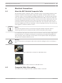
4
Product Description | en
15
Product Description
MIC Series 440 cameras are high-specification, weatherproof, ruggedized, fully functional day/
night PTZ cameras that have been designed to offer a reliable, robust, and high-quality
surveillance solution for extreme security applications.
MIC440 models have a 18x or 36x optical zoom (12x digital) and flexible mounting options
(upright or inverted) to achieve the perfect field of view.
MIC440 cameras meet the requirements of ATEX Directive 94/9/ EC Exd IIC T6 and CSA Class
I, Division 1, Groups CD, Class II, Division 1, Groups EFG, T6 for safe use in explosive
atmospheres such as those found in oil, gas, chemical processing sites, and petrochemical
refineries.
Precision-engineered to exacting standards, MIC cameras offer numerous benefits over
traditional dome and PTZ cameras. Rated to an industry-leading IP68, the compact, vandalresistant, 6 mm thick aluminum camera housing is pre-treated and then painted with polyester
powder coat paint (Jet black (RAL 9005) or Signal white (RAL 9003)). Brushless motor
technology ensures ultra-reliable, whisper quiet operation with full 360° continuous pan and
320° tilt control. The optically perfect, flat viewing window and integrated wiper ensure that
razor-sharp images are captured in even the most demanding conditions.
The following table identifies the mounting accessories for MIC440 cameras. Refer to the
datasheet MIC Series Mounting Brackets and Other Accessories for details.
MIC-SCA
Shallow Conduit Adapter
MIC-CMB
Corner Mount Bracket
MIC-PMB
Pole Mount Bracket
MIC-WMB
Wall Mount Bracket
MIC-SPR
Spreader Plate
A long-life silicone wiper blade mounted on a spring-loaded arm is standard on all MIC
cameras.
The following table identifies the accessories (not including mounting brackets) for MIC440
cameras.
Description
Accessories
MIC-ALM
MIC-WKT
Alarm and washer pump drive card for non-IR PSU; 8 inputs.
Washer kit, containing mounting bracket, nozzle, and washer pump
drive card.
MIC-BP4
Bosch Biphase converter card for MIC power supplies with an
available expansion slot.
A two-part plastic sunshield to provide additional protection in sunny
MIC440SUNSHIELD
climates for MIC cameras Comes with stainless steel bosses, washers,
and retaining screws.
Bosch Security Systems, Inc.
Operation Manual
2013.11 | 8.1 |
16
en | Installation of a MIC440 Camera
MIC440 Explosion-protected Camera
Installation of a MIC440 Camera
5
This chapter provides an overview for the installation of a MIC440 camera.
Caution!
The MIC440 camera is designed for use with flammable gases and vapors covered by
!
apparatus groups IIA, IIB and IIC and with temperature class T6. The product is certified for
use within the ambient temperature range of -20 °C to +60 ºC and must not be used outside
this range.
While a MIC440 camera is certified for installation in a hazardous area, its power supply unit
(PSU) is not. The PSU itself can be installed in either a non-hazardous area or in a hazardous
area. If installed in a hazardous area, the PSU must be placed inside a certified enclosure that
is certified for use in hazardous areas.
Warning!
!
5.1
ROUTING OF EXTERNAL WIRING MUST BE DONE THROUGH A PERMANENTLY EARTHED
METAL CONDUIT.
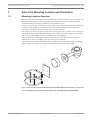
Mounting the Conduit Gland and Cable
The MIC composite cable (8 mm) required to connect the MIC440 to its power supply consists
of two pairs (24AWG) plus 4 cores of (22 AWG), 2 cores of (24 AWG), and one coax core for
the video signal to a maximum distance of 25 m.
Warning!
!
Bosch recommends connecting the cable to the unit before taking the unit for mounting onsite.
To mount the conduit gland and cable, follow these steps:
1.
Remove the 4 x M8 Hexagon bolts holding the conduit adapter (DCA) to the MIC440 unit.
Remove the DCA.
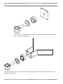
2.
Fit the unterminated ends of the composite cable through the 20 mm threaded gland hole
in the DCA. Allow approximately 100 mm of free cable on the inside to connect to the 12way cable connector.
3.
Screw the Exd conduit gland into the DCA, maintaining approximately 100 mm of cable
on the inside of the DCA to enable the cable connector to be inserted freely into the MIC
unit base connector.
4.
Connect the 12-way cable connector into the matching connector in the base of the MIC
unit.
5.
Ensure that the connector is fitted properly in the camera’s integral plug. Turn the socket
thread ring approximately two and a half turns to fasten the two halves of the connectors
together properly.
6.
Bolt the DCA onto the MIC440 unit; tighten the 4 x M8 hexagon bolts.
7.
Ensure that there are no trapped cables.
8.
Ensure that there is some slack cable in the DCA, then tighten and seal the Exd barrier
gland per the instructions included with the gland. The unit with the cable tail is now
ready for on-site installation.
2013.11 | 8.1 |
Operation Manual
Bosch Security Systems, Inc.
MIC440 Explosion-protected Camera
Installation of a MIC440 Camera | en
17
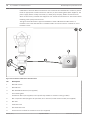
PSU Installation and Setup in a Non-Hazardous Area
5.2
The figure below illustrates an installation of a MIC PSU for MIC440 in a non-hazardous area.
Note that the camera itself is installed in a hazardous area.
Figure 5.1: Installation of MIC PSU in Non-Hazardous Area
1
MIC440 camera
2
Exd conduit gland
3
Composite cable inside metal conduit
4
Distance of 25 mm maximum
5
Hazardous area
6
Exd Barrier
7
Non-hazardous Area
8
Standard MIC PSU
PSU Installation and Setup in a Hazardous Area
5.3
Caution!
Any junction box or enclosure used for mounting the power supply or separating cable cores
MUST BE appropriately rated for the installation. MIC PSU enclosures are not Exd rated and
!
must be placed inside a certified enclosure if installed within a hazardous area.
For additional protection in hazardous area installations, suitable metal conduit must be used
externally for the composite cable run to connect the power supply to the Exd conduit gland
(not supplied) in the Deep Conduit Adapter (MIC-DCA).
Bosch Security Systems, Inc.
Operation Manual
2013.11 | 8.1 |
18
en | Installation of a MIC440 Camera
MIC440 Explosion-protected Camera
Installation of the PSU within a hazardous area must have the standard PSU enclosure placed
inside an appropriate certified enclosure and four (4) Exd conduit glands (NOT supplied). The
power supply PCB is usually re-housed, by a third party company, within an Exd enclosure
which is then factory certified and shipped to site. Follow all manufacturers’ instructions when
installing a third party Exd enclosure.
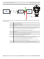
The figure below illustrates a typical installation of both a MIC440 and a MIC PSU in a
hazardous area. Note that the PSU is installed inside an enclosure that is certified for use in
hazardous areas.
Figure 5.2: Installation of MIC PSU in Hazardous Area
No.
Description
1
MIC440 camera
2
MIC440 DCA
3
MIC Wall Mount Bracket (not supplied)
4
Exd conduit gland
Exd Barrier Gland (not supplied; to be specified by installer to match incoming conduit)
5
MIC composite cable (length to be specified; 25 m maximum) inside metal conduit (not supplied)
6
MIC PSU
7
Hazardous area
8
Non-Hazardous area
9
Exd Enclosure certified for hazardous areas (not supplied)
2013.11 | 8.1 |
Operation Manual
Bosch Security Systems, Inc.
MIC440 Explosion-protected Camera
5.4
Installation of a MIC440 Camera | en
19
MIC Power Supply Unit Extension
Users can extend the distance between their MIC camera and the MIC PSU by using two
junction boxes (user-supplied). The boxes must be weatherproof or explosion-proof,
depending on the model and the physical location of the box. The second junction box is
required to reduce the size of the cable and to reduce the amount of conduit connections to
the MIC PSU.
All cables used outdoors must have a UV-resistant outer jacket, or must be installed inside
permanently earthed metal conduit. See the table below for the maximum distance and wire
gauge recommended for each camera. The maximum distance is the distance between the two
user-supplied junction boxes.
Wire Gauge
18 AWG
16 AWG
14 AWG
12 AWG
Maximum Distance in Meters (feet)
46 (151)
73 (240)
116 (381)
185 (606)
Maximum Watts, MIC440 = 25.2.
Bosch Security Systems, Inc.
Operation Manual
2013.11 | 8.1 |
20
en | Installation of a MIC440 Camera
MIC440 Explosion-protected Camera
Figure 5.3: MIC PSU Extension with two (2) user-supplied junction boxes (weatherproof or explosion-proof, depending on model
and physical location)
1
Head-end control system
2
Standard cables and power
3
MIC PSU
4
Standard MIC composite cable (2 meters MAXIMUM)* inside metal conduit
5
First user-supplied Junction Box (weatherproof or explosion-proof).
See the Caution boxes at the beginning of the subchapter.)
6
RG59U Coax
7
RS-485 (2- or 4-wire shielded twisted pair with ground)
8
Power wires, which control the maximum distance.
See the table below for limitations.
9
Second user-supplied Junction Box (weatherproof or explosion-proof).
See the Caution boxes at the beginning of the subchapter.)
This second box is required to reduce the size of the cable and to reduce the
amount of conduit connections to the MIC PSU.
10
2013.11 | 8.1 |
Standard MIC composite cable (2 meters MAXIMUM)* inside metal conduit
Operation Manual
Bosch Security Systems, Inc.
MIC440 Explosion-protected Camera
Electrical Connections | en
6
Electrical Connections
6.1
About the MIC Shielded Composite Cable
21
All connections (power, telemetry, video) to the MIC camera are provided through the screw
terminal connections in the MIC power supply. MIC shielded composite cables are multiconductor cables of various lengths (and gauges ranging from 14 - 18) that provide all power,
video, and telemetry connections between the MIC PSU and the MIC camera. The cables are
pre-made with a female terminated connector (12-pin) at one end for attachment to the male
connector installed into the base of the camera. The other end of the cables has free (nonterminated) wires for wiring into terminals in the MIC PSU. The composite cable consists of
two pairs (24AWG) plus 4 cores of (22 AWG), 2 cores of (24 AWG), and one coax core for the
video signal to a maximum distance of 25 m.
Notice!
Bosch Security Systems does not recommend using the shielded composite cable for
distances greater than 25 m between the MIC camera and the MIC power supply.
For installations that require the camera to be more than 25 m from the power supply, Bosch
recommends that a 2 m cable be connected to a junction box (Exd rated for MIC440) from
which telemetry, video, and power can be broken out into separate cables and appropriate
wiring used to extend the distance to suit.
Warning!
!
Bosch recommends connecting the cable to the unit before taking the unit for mounting onsite.
MIC shielded composite cable before connection to a MIC440 camera
MIC shielded composite cable connected to a MIC440 camera
6.2
Composite Cable Color-coding
The standard color coding used in MIC composite cables is as follows:
Bosch Security Systems, Inc.
Operation Manual
2013.11 | 8.1 |
22
en | Electrical Connections
MIC440 Explosion-protected Camera
Figure 6.1: Exploded View of Composite Cable Connections
Camera
Signal Name
Description
Cable
Cable Wire
Color
Connector
Pin
1
Washer Drive Rtn
Auxiliary Connection
Grey
2
Tamper Sw Rtn
Auxiliary Connection
Brown
3
Washer Drive
Wash Signal
Orange
4
Tamper Sw
Alarm Communications
Black
5
Video Return
Video Signal Ground
Coax
Screen
6
Video Output
Video Output to Control Room
Coax Core
7
Full Duplex Tx B+
Telemetry I/O to RS-422/485
Violet
8
Full Duplex Tx A-
Telemetry I/O to RS-422/485
Blue
9
0v
Ground
Shield
10
Full Duplex Rx A-
Telemetry I/O to RS-422/485
Yellow
Telemetry I/O to RS-422/485
White
Half Duplex Tx/Rx A
11
Full Duplex Rx B+
Half Duplex Tx/Rx B
12
Power Input 2
Low Voltage Power Input
Green
13
Power Input 1
Low Voltage Power Input
Red
Video output signal conforms to CCIR PAL or NTSC 1V Composite format. Telemetry signals all
conform to the RS-485 / RS-422 standard. The unit continuously monitors incoming telemetry
whether in full or half duplex mode.
In full duplex mode, the Tx pins are tri-state except during transmission times. This may cause
problems when interfacing to some fiber optic converter units. Check out the Commissioning
notes for ways of overcoming these problems. In 2 wire Half Duplex mode (RS-485), the Rx
pins are used to transmit data to the MIC440.
The washer connections can be used to operate a relay in the power supply unit, which in turn
can activate a pump.
2013.11 | 8.1 |
Operation Manual
Bosch Security Systems, Inc.
MIC440 Explosion-protected Camera
Select the Mounting Location and Orientation | en
7
Select the Mounting Location and Orientation
7.1
Mounting Location Overview
23
MIC Series cameras are designed for easy installation in various locations such as directly onto
buildings and dedicated CCTV poles. Bosch sells a complete series of mounting brackets
designed to allow the camera to achieve the optimal field of view.
The most common type of mounting location is the top of a dedicated CCTV pole that provides
a robust mounting platform that minimizes camera motion and typically has a large base
cabinet for mounting ancillary equipment such as power supplies.
The camera can also be mounted on the side of a lamp post, pole, or similar column using the
Pole Mount Bracket (MIC-PMB). Be aware that lamp posts can often be subject to movement
and are not suitable platforms in all conditions or for all applications.
Other locations for mounting the camera include the top of a building, the side (wall) of a
building, the corner of a building, and under the eave of a building.
The three figures directly below illustrate the arrangement of mounting brackets for installing
a MIC camera. The camera (not shown) is attached to the bowl of the MIC-WMB.
Figure 7.1: Typical pole mount (from left: Pole Mount Bracket (MIC-PMB) [2 mounting blocks, 2 pole bands,
and 1 mounting plate], Shallow Conduit Adapter (MIC-SCA), and Wall Mount Bracket (MIC-WMB))
Bosch Security Systems, Inc.
Operation Manual
2013.11 | 8.1 |
24
en | Select the Mounting Location and Orientation
MIC440 Explosion-protected Camera
Figure 7.2: Typical wall mount (from left: Wall Mount Bracket (MIC-WMB), Shallow Conduit Adapter (MICSCA), and Spreader Plate (MIC-SPR))
Figure 7.3: Typical corner mount (from left: Wall Mount Bracket (MIC-WMB), Shallow Conduit Adapter (MIC-SCA), and Corner
Mount Bracket (MIC-CMB))
2013.11 | 8.1 |
Operation Manual
Bosch Security Systems, Inc.
MIC440 Explosion-protected Camera
7.2
Select the Mounting Location and Orientation | en
25
Select the Mounting Location
1. Select the mounting location.
Select a secure installation location and mounting position for the device. Ideally, this is a
location where the device cannot be interfered with either intentionally or accidentally.
Ensure that the location has the appropriate clearance from power and lightning conductors,
in accordance with NEC725 and NEC800 (CEC Rule 16-224 and CEC Section 60).
Do not install the device near:
–
Any heat sources
–
Any overhead power lines, power circuits, or electrical lights, or where the device may
contact power lines, circuits, or lights
4
Ensure that the selected mounting surface is capable of supporting the combined weight
of the camera and mounting hardware (sold separately) under all expected conditions of
load, vibration, and temperature.
Notice!
MIC cameras must be secured to one of the following surfaces:
- Concrete (Solid/Cast)
- Concrete Masonry Unit (Concrete Block)
- Brick (all types)
- Metal (Steel/Aluminum, minimum 1/8-in. thick)
Caution!
Risk of lightning strikes
If the camera is installed in a highly exposed location where lightning strikes may occur, then
Bosch recommends installing a separate lightning conductor within 0.5 m (1.6 ft) of the
!
camera and at least 1.5 m (4.9 ft) higher than the camera. A good earth bonding connection
to the camera housing itself will provide protection against damage from secondary strikes.
The camera housing itself is constructed to cope with secondary strikes. If the correct
lightning protection is applied, then no damage to the internal electronics or camera should
result.
7.3
Mounting Orientation
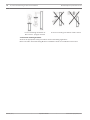
2. After selecting the mounting location, select the appropriate mounting orientation.
MIC Series cameras are designed to be mounted upright (straight up, 90°) or inverted
(straight down, 90°). See the figures below for illustrations of the correct and the incorrect
mounting orientations of MIC cameras.
Bosch Security Systems, Inc.
Operation Manual
2013.11 | 8.1 |
26
en | Select the Mounting Location and Orientation
MIC440 Explosion-protected Camera
Correct mounting orientation of
Incorrect mounting orientation of MIC camera
MIC camera - upright, inverted
3. Install the mounting brackets.
Observe all appropriate safety precautions and local building regulations.
Refer to the MIC Series Mounting Brackets Installation Guide for installation instructions.
2013.11 | 8.1 |
Operation Manual
Bosch Security Systems, Inc.
MIC440 Explosion-protected Camera
8
Mount the Camera | en
27
Mount the Camera
To mount a MIC Series camera, follow these steps:
!
Warning!
Ensure not to damage the paint work on the housing of the camera or the mount.
1. Carefully lift the camera to the mounting location.
2. Connect the female cable connector end (12-pin) of the shielded composite cable to the
male plug in the base of the camera. Screw the cable connector sleeve onto the plug until it is
secured firmly (approximately four (4) turns from the start of thread engagement).
Bosch Security Systems, Inc.
Operation Manual
2013.11 | 8.1 |
28
en | Earthing the Camera
MIC440 Explosion-protected Camera
Earthing the Camera
9
Earth the MIC Camera to metal on or attached to the mount.
!
Warning!
The camera must be earthed / grounded to meet EMC immunity standards.
Earth the camera using one of the supplied securing bolts. Only earth the camera at a single
point to prevent earth loops and video distortion (hum bars), caused by electrical
interference, from appearing on the camera picture in the control room. Please note:
–
The camera module and housing are electrically isolated, so the housing should be safety
earthed regardless. The safety earth should be a bonding connection (for example, one of
the securing bolts) to the camera housing, or should be attached to the Earth terminal
post on the PCD base of the camera.
–
If the system is copper throughout and the camera pictures are fed back to the control
room via coaxial copper cable, then the camera should be earthed only at the video
termination point in the control room. In this case, the "Earth Link" on the PCB should be
broken. Refer to Earth Link on PCB, page 30.
–
If the video is transmitted back to the control room via some non-electrical connecting
medium (for example, fiber optic, radio, or microwave link), then the camera should be
earthed at the transmitter point in the power supply unit. The PSU "Earth Link" may be
used for this purpose.
–
If dual earthing is unavoidable, then a video isolation transformer should be fitted
between the two earths.
2013.11 | 8.1 |
Operation Manual
Bosch Security Systems, Inc.
MIC440 Explosion-protected Camera
10
Finalize Camera Mounting | en
29
Finalize Camera Mounting
Finalize Camera Mounting
Warning!
It is essential that the connections and the base of the camera are completely sealed from
!
water ingress. Any water getting into the connector is liable to cause corrosion to the
connector pins, leading to unreliable operation of the camera unit. This is especially
imperative for a camera mounted in inverted orientation.
1. To prevent water ingress, seal the threads of the securing bolts using PTFE tape (not
supplied). An additional gasket or suitable silicone sealant can be applied liberally to the
threads prior to final tightening to ensure a watertight seal between the base of the camera
and the mounting surface.
2. Use M8 x 20 mm stainless steel nuts, bolts, and washers to secure the base of the camera
to the mounting surface.
3. Tighten all bolts securely.
4. Secure all cabling and conduit.
Caution!
!
The upright unit can be mounted either with the camera ball up or down. So that the picture
from a camera installed with the camera ball down appears properly, rotate the camera tilt
axis 180°. For more information, see Configuring the Camera for Inverted Operation, page 44.
Bosch Security Systems, Inc.
Operation Manual
2013.11 | 8.1 |
30
en | Install the MIC Power Supply Unit (PSU)
MIC440 Explosion-protected Camera
11
Install the MIC Power Supply Unit (PSU)
11.1
MIC PSU Overview
Caution!
!
Use only the power supply specified for your specific model of camera.
Bosch provides a range of power supply units (PSUs) for MIC Series cameras. These units
have a variety of common voltages and provide all the connections needed for power,
telemetry and video.
Warning!
!
These power supply units are NOT explosion-proof and must be installed outside of the
hazardous environment.
Each MIC PSU provides all of the connections needed for power, video, and telemetry for a
single MIC camera. Each MIC PSU has CE and FCC approval and has a cast-aluminum
enclosure that is weather-resistant (rated IP65). Features include:
–
A provision for driving various optional interface cards mounted internally to the MIC
power supply enclosure (for example, an 8-input alarm card (MIC-ALM))
–
A provision for a signal interface card (MIC-BP4) to connect telemetry to Bosch Biphase
equipment
–
Screw termination of all cables (composite, telemetry, and ancillary) into and out of the
enclosure
–
Earth isolation and termination within the unit to control video earthing correctly and
thus prevent earth loops
Each MIC PSU ships with the following parts:
–
Three (3) M12 cable glands for telemetry, video and ancillary equipment
–
One (1) M16 gland for connection of the shielded composite cable to the MIC camera
–
One (1) 1/2 in. NPT cable gland for the power cable connection
–
One (1) 1/2 in. NPT and one (1) M12 blanking plug
The transformer fitted to these designs is thermally protected and automatically cuts out if the
transformer core temperature exceeds 40 degrees C. On cooling, the transformer will become
operational again. In addition, the unit provides all the terminations required to connect a
MIC440 camera to third party equipment. A second, independent 12v (600mA) power supply
is also included to drive any internally fitted optional interface cards.
11.2
Earth Link on PCB
The printed circuit board (PCB) of each MIC PSU (IR and non-IR) has one Earth Link option,
near terminal block HD1, to allow the PSU to be set up for different earthing schemes:
–
If there is a separate connection between video screen and earth, the Earth Link should
be broken. This usually occurs on copper-connected systems where all of the copper
video coaxes are taken back to the control room to be connected to a central earth point.
–
If fiber optics or other indirect connections are used to get data and video to and from
the control room, then the Earth Link should be left intact, as long as it is the only
camera-end earth reference point.
2013.11 | 8.1 |
Operation Manual
Bosch Security Systems, Inc.
MIC440 Explosion-protected Camera
Install the MIC Power Supply Unit (PSU) | en
31
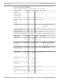
Fuse Ratings
11.3
The MIC PSUs for MIC440 cameras have four (4) off 20 mm fuses (numbers 13 - 16 in the
figure “Layout of MIC-240PSU-2 and MIC-115PSU-2”) in fuse holders. The ratings for these
fuses are fixed on the low voltage secondary side but change with input voltage on the high
voltage primary side. The following table shows the fuse values that should be fitted to
provide proper protection for the MIC-240PSU-2 and MIC-115PSU-2 power supplies. Note: FS
4 does not exist.
Fuse
Fuse Function
Type
ID
FS 1
MIC camera
Rating for 240 V
Rating for 115 V
Rating for 24 V
Primary
Primary
Primary
Glass
1.6 A anti-surge (T)
1.6 A anti-surge (T)
1.6 A anti-surge (T)
protection
FS 2
Primary protection
Glass
200 mA quick blow
500 mA quick blow
2.5 A quick blow
FS 3
Heater protection 1
Glass
1.6 A anti-surge (T)
1.6 A anti-surge (T)
1.6 A anti-surge (T)
FS 5
Heater protection 2
Glass
1.6 A anti-surge (T)
1.6 A anti-surge (T)
1.6 A anti-surge (T)
11.4
Alarm Inputs
The table below identifies the number of alarm inputs and outputs available in MIC power
supply units, depending on whether or not an 8-input alarm card is installed.
MIC PSU
8-input Alarm Card
Number of
Number of
(MIC-ALM)?
Alarm Inputs
Alarm Outputs
No
1
0
Yes
8
2
MIC-24PSU-2,
MIC-115PSU-2,
MIC-240PSU-2
Table 11.1: Number of alarm inputs and outputs in MIC PSUs
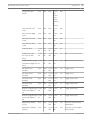
11.5
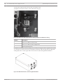
Layout of MIC Power Supply Units (PSUs)
Layout of MIC-240PSU-2 and MIC-115PSU-2
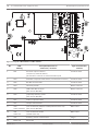
The figure below displays the layout of the PCB in the MIC PSUs for non-IR cameras, with callout numbers to the side of or below the connection/terminal ID or the terminal, and ’on’ the
fuses. The table below the figure identifies the connections.
Bosch Security Systems, Inc.
Operation Manual
2013.11 | 8.1 |
32
en | Install the MIC Power Supply Unit (PSU)
MIC440 Explosion-protected Camera
Figure 11.1: Layout of MIC-240PSU-2 and MIC-115PSU-2
No.
1
PCB
Description/Function of
Type of Connection/
Marking
Connection / Terminal
Terminal
HD1
AC Power input connector
Screw terminal
Live (HD1-1); Neutral (HD1-2)
[Ground wire connects to earth termination post
2
HD3
Shielded composite cable header (connections to camera)
Screw terminal
3
HD5
RS-485 control header
Screw terminal
4
HD4
Telemetry header
Molex connector
5
HD8
USB to RS-485 converter
Molex connector
[Not used for MIC440.]
6
HD6
[Optional] Auxiliary, heater
Screw terminal
[Not used for MIC440.]
7
HD7
Video (composite cable)
Screw terminal
8
HD2
Tamper switch header
Screw terminal
9
CN3
Coax connection (Switched visible/thermal video out)
BNC socket
Video Switched
[Not used for MIC440.]
CN1
Coax connection header
Video Out
(Visible video out)
11
CN2
Auxiliary / add-on card terminal
12
Earth Link
Earth Link
10
2013.11 | 8.1 |
Operation Manual
BNC socket
Plug in
Bosch Security Systems, Inc.
MIC440 Explosion-protected Camera
No.
Install the MIC Power Supply Unit (PSU) | en
PCB
Description/Function of
Type of Connection/
Marking
Connection / Terminal
Terminal
13
FS2
Fuse 2 - Primary protection
--
14
FS1
Fuse 1 - MIC camera protection
--
15
FS3
Fuse 3 - Heater protection 1
--
16
FS5
Fuse 5 - Heater protection 2
--
17
--
Earth termination post
Ring terminal
11.6
33
Installation Instructions (Power Supply)
Danger!
ELECTRICAL SHOCK HAZARD
To reduce the risk of electrical shock, disconnect power before opening or working on any
power supply unit. Power must be disconnected before replacing any fuse in the MIC PSU.
Power supply units have power supplied whenever the power cord is inserted into the power
source.
MIC PSUs have a separate internal shield covering the power cable input terminal block
(HD1). Only suitably qualified persons should remove this shield and connect the mains power
cable. The shield MUST be re-installed and fully secured before connecting the power.
The power supply cable shall have conductors of a maximum size of 12 AWG.
Branch circuit protection incorporating a 15 A, 2-pole, listed circuit breaker or branch rated
fuses are required. A readily accessible 2-pole disconnect device with a contact separation of
at least 3mm must be incorporated externally to the equipment.
Warning!
!
To meet UL standards and ratings, all external wires for installation applications must be
routed through a permanently earthed metal conduit.
Caution!
!
Except for the Earth Link, heater links, and applicable fuses, the MIC PSUs have no useradjustable parts. MIC cameras have no user-serviceable parts.
Caution!
!
Bosch recommends using an uninterruptible power supply (UPS) in connection with a MIC
camera/PSU installation.
Notice!
To maintain the IP rating of the power supply enclosure, install only listed or recognized
conduit hubs or fittings with the same environmental rating as the enclosure in compliance
with the installation instruction of the hub or fitting.
Notice!
Refer to the MIC Series Power Supply Installation Manual included with the PSU for full details
on installing a MIC Series PSU and connecting to a MIC Camera.
Bosch Security Systems, Inc.
Operation Manual
2013.11 | 8.1 |
34
en | Install the MIC Power Supply Unit (PSU)
MIC440 Explosion-protected Camera
To install the power supply unit (PSU), follow these steps:
1. Select a secure installation location for the PSU. Ideally, this is a location where the device
cannot be interfered with either intentionally or accidentally.
Bosch recommends using an environmentally suitable, lockable equipment cabinet.
2. Locate the four (4) mounting holes of the power supply enclosure.
3. Drill four (4) holes in the mounting surface for the mounting anchors appropriate for M6
screws (not supplied).
4. Loosen the four (4) captive Phillips head screws on the top of the lid of the power supply
enclosure. Lift the lid and set it upside down next to the enclosure.
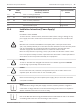
Notice!
Do not stretch or cut, or otherwise disturb, the earth core cable (shown in the figure below)
to the inside of the lid and to the earth termination post.
Figure 11.2: Holes for screws for mounting enclosure mounting; holes for screws for enclosure lid
Number
Description
1
Hole for mounting screw in enclosure
2
Hole for lid screw in enclosure
5. Secure the enclosure to the mounting surface using four (4) M6 stainless steel screws and
washers (not supplied), which fit through the large holes in the enclosure.
Notice!
If you are securing the power supply enclosure in a vertical position (for example, on a wall),
one person should hold the enclosure lid while another secures the enclosure body in place,
to avoid damage to any part of the enclosure, and/or injury to the installer(s).
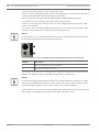
6. Unscrew the two (2) M3 screws on the internal high voltage input head-end shield (marked
with "Danger") covering the mains cable terminal HD1; retain the screws.
2013.11 | 8.1 |
Operation Manual
Bosch Security Systems, Inc.
MIC440 Explosion-protected Camera
Install the MIC Power Supply Unit (PSU) | en
35
Figure 11.3: Enclosure showing shield and earth core cable between earth terminal post and enclosure lid
Number
Description
1
Earth core cable to enclosure lid
2
Internal shield
3
Earth termination post
7. Remove the internal shield and set it nearby, outside of the PSU enclosure. You can now
access the hole for the power cable and the M20 blanking plug covering the hole.
8. Remove the blanking plug. Install suitable (metal) conduit in place of the blanking plug.
Secure the conduit as recommended by the conduit manufacturer.
Caution!
Only installations with conduit meet UL standards. If you choose to use a power cord without
conduit (not recommended), fit the 1/2 in. NPT cable gland (supplied) in place of the
!
blanking plug. Note: It is easier to fit the power cord through the cable gland outside of the
enclosure, and then attach the gland to the enclosure. Ensure that the cable glands have
sufficient room to allow for the cables to enter (approximately 60 mm on either side of the
enclosure).
9. Prepare the power cable as need, and then feed the cable into the enclosure.
10. Connect the Live and Neutral cores to the correct screw terminals on terminal block HD1
as identified in the table below and printed on the PCB. Observe polarity and voltage.
PCB Marking
Description
L
Live
N
Neutral
Earth / Ground
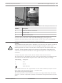
11. Remove the brass nut and copper washer from the earth termination post (item 3 in the
figure “Mains input with shield removed…”); set these aside.
12. Remove the ring terminal (supplied).
13. Insert the earth core from the mains cord (item 2 in the figure “Mains input with shield
removed…”) into the crimp portion (size M6, UL-certified) of the ring terminal and crimp it in
place.
Bosch Security Systems, Inc.
Operation Manual
2013.11 | 8.1 |
36
en | Install the MIC Power Supply Unit (PSU)
MIC440 Explosion-protected Camera
14. Place the ring terminal onto the earth termination post.
15. Replace the copper washer. Secure with the brass nut.
Figure 11.4: Mains input with shield removed, showing terminal block HD1 before wiring
Number
Description
1
Earth core cable to enclosure lid
2
Earth core cable to power supply PCB
3
Earth termination post
16. Replace the internal shield, taking care to avoid pinching the cables. Tighten the screws.
17. Feed the unconnected end of the shielded composite cable through the top-right M16
cable gland (item 2 in the figure “MIC PSU Enclosure, with cable glands identified”).
Figure 11.5: MIC PSU Enclosure, with cable glands identified
2013.11 | 8.1 |
Operation Manual
Bosch Security Systems, Inc.
MIC440 Explosion-protected Camera
Install the MIC Power Supply Unit (PSU) | en
Number
Description
Cable Gland Size
1
Optical Video out
M12
2
Composite cable
M16
3
Optional switched video output
M12
4
Head-end / Telemetry controls
M12
37
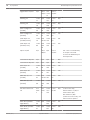
18. Connect the shielded composite cable to terminal block HD3 (and, if necessary, HD6 and
HD7) following the color coding as shown in the figure below, and printed on the PCB.
No
ID, Connection/
PCB Mark,
.
Terminal + Pin
Signal
Description/Function of Connection
PCB Mark,
1
HD3-1
Power
Low Voltage Power (Input 1) / AC supply
Red
2
HD3-2
Power
Low Voltage Power (Input 2) / AC supply return
Green
3
HD3-3
RxB
Telemetry I/O to RS-422/485 [Rx +]
White
Cable Color
Full Duplex RxB/Half Duplex Tx/RxB
4
HD3-4
RxA
Telemetry I/O to RS-422/485 [Rx -] Full Duplex
Yellow
RxA/Half Duplex Tx/RxA
5
HD3-5
0v
Ground [Drain Wire / Shield]
Screen (Black)
6
HD3-6
TxA
Telemetry I/O to RS-422/485 [Tx -] Full Duplex
Blue
TxA
7
HD3-7
TxB
Telemetry I/O to RS-422/485 [Tx +] Full Duplex
Violet
TxB
8
HD3-8
Video
Video output of optical camera to Control Room
Core
(Coax - BNC CN1)
9
HD3-9
Video 0V
Video signal return (optical camera) (ground to
Screen
Control Room) (Coax - BNC CN1)
10
HD3-10
Tamp Sw
[Optional] Tamper Switch
Black
11
HD3-11
Wash
[Optional] Washer Drive Signal
Orange
12
HD6-1
AUX1
[Optional] Auxiliary Connection (heater)
Brown
13
HD6-2
AUX2
[Optional] Auxiliary Connection (heater)
Grey
14
HD7-1
--
Video Switched Output to Control Room
Core (Black)
(Switched visible/thermal video out signal)
15
HD7-2
--
Switched video signal ground
Screen (Black)
Notice!
MIC440 cameras do not have an internal heater.
19. Slide back the cable so that the shield is in the middle of the gland.
20. Tighten the cable gland so that it grips firmly the shielded composite cable. It is important
that the braided cable screen engages with the internal clamps of the cable gland to ensure
correct EMC protection.
Bosch Security Systems, Inc.
Operation Manual
2013.11 | 8.1 |
38
en | Install the MIC Power Supply Unit (PSU)
MIC440 Explosion-protected Camera
21. If necessary, connect a tamper switch to terminal block HD2.
22. Make the necessary video connections. Feed the coaxial cable of your choice--see the table
below to identify the recommended cable types, maximum distance, and other specifications
for the coax video connection between the MIC power supply and the head-end control
system--through the top-left M12 cable gland (item 1 in the figure “MIC PSU Enclosure, with
cable glands identified”).
Cable Type; Maximum
RG-59/U; 300 m (1000 ft)
Distance
RG-6/U; 450 m (1500 ft)
RG-11/U; 600 m (2000 ft)
Size
O.D. between 4.6 mm (0.181 in.) and 7.9 mm
(0.312 in.)
Shield
Copper braid: 95%
Central Conductor
Standard copper center
23. Crimp the end of the cable with a BNC terminal connector.
24. Connect the Video Out cable to BNC socket CN1.
25. Feed telemetry cable through the bottom-right M12 cable gland (item 4 in the figure “MIC
PSU Enclosure, with cable glands identified”).
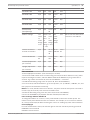
26. Connect head-end RS-485 control to terminal block HD5, as indicated in the table below:
Telemetry Signal Name
Connection Description / Function
Pin Number
RxB
Rx +
RS485+ to camera
1
RxA
Rx -
RS485- to camera
2
0V
Ground
0V from control room
3
TxA
Tx -
RS485- to control room
4
TxB
Tx +
RS485+ to control room
5
PCB Marking
(non-IR PCBs)
Note: The terminal block is positioned with the screw terminals on the left, next to the fuses.
Pins are numbered from top to bottom in that orientation. Non-IR PSU PCBs are marked.
27. If connecting to additional add-on cards (for example, a card for 8-input alarms (MICALM), and/or a Biphase card (MIC-BP4)), remove the second blanking plug that covers one of
the holes for an M12 cable gland (item 3 in the figure “MIC PSU Enclosure, with cable glands
identified”). Attach the supplied M12 gland. Make the appropriate connections to plug-in
terminal CN2.
Notice!
For installation of the MIC 8-input Alarm Card (MIC-ALM) or Biphase converter (MIC-BP4),
please refer to their respective manuals.
28. After wiring is complete, connect the power supply to the power source.
29. Verify that the following LEDs are lit:
2013.11 | 8.1 |
LED
Description
LED 2
18 VAC power on to camera
LED 4
Power on for optional heater
Operation Manual
Bosch Security Systems, Inc.
MIC440 Explosion-protected Camera
Install the MIC Power Supply Unit (PSU) | en
LED
Description
LED 3
18 VAC power on camera
LED 5
Power on for optional heater
39
30. Re-attach the enclosure lid and tighten the four (4) captive screws on the cover to ensure
that the enclosure is watertight.
Bosch Security Systems, Inc.
Operation Manual
2013.11 | 8.1 |
40
en | Fit the Optional Sunshield (MIC440)
12
MIC440 Explosion-protected Camera
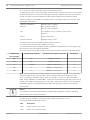
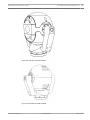
Fit the Optional Sunshield (MIC440)
The MIC440 Sunshield is designed to provide additional protection against direct solar
radiation by reflecting solar exposure and creating an insulating gap between the environment
and the surface of the camera. It is a two (2) part moulding and comes supplied with four (4)
stainless steel set screws.
Caution!
!
DO NOT REMOVE the lid from the camera, and do not back drive the pan or tilt axis manually.
Doing so will void the warranty. Back driving may also strip teeth off the internal gears.
To fit the sunshield, follow these steps:
1.
Turn on the power to the camera so that you can rotate the camera head up to fit the
bottom half of the sunshield (steps 2 through 4).
2.
Rotate the camera under power--do not rotate by hand--until the bottom of the camera
head is facing up.
3.
Align the 4 posts/alignment tabs and the two screw holes of one piece of the sunshield
with the corresponding posts and holes on the camera head. Push the sunshield until it
fits snugly onto the camera head.
4.
Place two of the socket head screws into the screw holes. Fasten the screws with a Torx
wrench.
5.
Rotate the camera under power--do not rotate by hand--until the top of the camera head
is facing up.
6.
Repeat steps three and four for the second half of the sunshield. When fitted properly,
both halves of the sunshield should align and meet at the back of the camera head.
Figure 12.1: Sunshield and Screws being placed
2013.11 | 8.1 |
Operation Manual
Bosch Security Systems, Inc.
Fit the Optional Sunshield (MIC440) | en
MIC440 Explosion-protected Camera
41
Figure 12.2: Side View of Fitted Sunshield
Figure 12.3: Back View of Fitted Sunshield
Bosch Security Systems, Inc.
Operation Manual
2013.11 | 8.1 |
42
en | Connection
MIC440 Explosion-protected Camera
13
Connection
13.1
Connection Overview
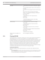
Connecting and configuring MIC cameras
To configuration and operate/control the camera, you will need a computer, either an RS-232
to RS-485 adapter or a USB to RS-485 adapter, and the MIC Series Universal Camera Setup
Software (“Camset”). The Camset software is provided on the CD that comes with each
camera. Refer to the Universal Camera Setup Software User Guide for details.
Typically the RS-232/RS-485 adapter is connected to a serial port on a computer. The port will
generally be assigned to Comm Port 1.
If your computer does not have a serial port, you can use the MIC-USB485CVTR2 converter to
connect to the MIC power supply, or you can use the camera’s on-screen menu function.
13.2
Connecting the USB to RS-485 Converter
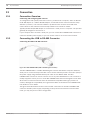
Connecting the USB to RS-485 Converter
Figure 13.1: MIC-USB485CVTR2 (USB to RS-485 signal converter)
The MIC-USB485CVTR2 is a USB to RS-485 signal converter that allows computers without a
serial port to connect directly to the MIC camera via the telemetry header connection (HD4) in
the power supply using standard twisted pair cable such as Belden 8760. The MICUSB485CVTR2 can also be used to connect a PC to any other RS-485 device. The converter is
usually mapped to Comm port 3 or 4.The MIC-USB485CVTR2 has been designed to work with
all functions in Universal Camset and to be backwards-compatible with legacy versions of
Camset, although full compatibility is not guaranteed. Refer to the MIC Series USB485CVTR2
User Guide for more details.
The figure below illustrates how the screw terminal connections on the MIC-USB485CVTR2
connect to the MIC power supply. Depending on the protocol and selected communication
mode, you may only need a 2-wire configuration.
2013.11 | 8.1 |
Operation Manual
Bosch Security Systems, Inc.
MIC440 Explosion-protected Camera
Connection | en
43
Figure 13.2: MIC-USB485CVTR2 to MIC Series Power Supply Unit Telemetry Header Cable
Number
Color
Converter
Number
Color
Output
Telemetry Header
Communication Mode
(HD4 or HD5)
in Power Supply
1
Black
RxB/Rx -
6
Black
TxB
2
Red
RxA/Rx +
7
Red
TxA
3
(Shield)
GND/0V
8
(Shield)
GND
Shield (always)
4
Green
TxA/Tx -
9
Green
RxA
Simplex
5
White
TxB/Tx +
10
White
RxB
Bosch Security Systems, Inc.
Operation Manual
Full Duplex (4-wire only)
Hall Duplex (2-wire)
Full Duplex (4-wire)
2013.11 | 8.1 |
44
en | Configuration
MIC440 Explosion-protected Camera
14
Configuration
14.1
Addressing the Camera
Addressing the camera using Bosch protocol with Camset 4.12.00.06
The camera accepts a custom string of commands that change the camera address. The
following procedure uses hexadecimal numbers to identify the camera address. Bosch
recommends using a calculator with a decimal to hexadecimal converter to obtain the correct
hexadecimal value for the address. (The Calculator included with Microsoft Windows
operating systems contains a converter in the Programmer mode).
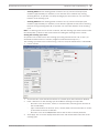
1.
Launch Camset 4.12.00.06 and ensure that you can control camera.
2.
Select Send Custom Command from the Advanced Setup menu.
3.
Type the following string to send the AUX ON 14 command: 07,01,0E
4.
Click the Send Now button.
5.
Type the following string to send the AUX ON 21 command: 07,01,15
6.
Click the Send Now button.
7.
Type the following string to send the AUX OFF 21 command: 07,02,15
8.
Click the Send Now button.
9.
Type the following string to send the AUX OFF “new address” command and to set the
camera address: 07,02,xx
where “xx” is the hexadecimal address for the camera. For example, use “AB” to set the
camera address to 171.
4
14.2
Click the Send Now button. The camera address is set.
Configuring the Camera for Inverted Operation
The video display from a camera installed in inverted position will appear upside down until
you set the video orientation to “Inverted position.” Follow these steps:
1.
Access the main Setup Menu of the on-screen display (OSD). The screen Setup Menu
appears.
2.
Select the submenu “PTZ Setup.” The screen PTZ Setup appears.
3.
Select the option “Orientation.”
4.
Select the value “Inverted,” which rotates the video 180°. The video should now appear
upright.
2013.11 | 8.1 |
Operation Manual
Bosch Security Systems, Inc.
MIC440 Explosion-protected Camera
15
Operation | en
45
Operation
For operation of the MIC440, refer to the tables below for the list of support protocols and
commands.
Aux
Function
Description (MIC function)
1
Focus Control
On: Enables Manual Focus
Off: Disables Manual Focus => Auto Focus
2
Digital Zoom Enable
On: Digital Zoom is enabled
Off: Digital Zoom is disabled
3
Iris Control
On: Enables Manual Iris
Off: Disables Manual Iris => Auto Iris
4
Auto Lowlight
On: Enables Auto Lowlight, Decrease frame rate for low light conditions
Off: Disables Auto Lowlight, Returns to Auto Iris
5
Wiper
On: Wiper On
Off: Wiper Off
6
Washer
On: Washer On
Off: Washer Off
7
Proportional PTZ
On: Enabled, Pan and Tilt Speed is scaled according to Zoom position
Off: Disabled, Normal PTZ
8
IR Lamps
On: Switches IR Cut Filter & Lamps On
Off: Switches IR Cut Filter & Lamps Off
9
Camera Power
On: Video Output from Sony Camera module is enabled
Off: Video Output from Sony Camera module is disabled
10
Backlight
On: Backlight On
Off: Backlight Off
11
B&W
On: Black & White Mode
Off: Color Mode
12
OSD
On: Shows Sony camera module On-Screen-Display
Off: Hides Sony camera module On-Screen-Display
13
Shutter Speed (1/2 s)
On: Sets Shutter Speed to 1/2 s (fixed)
Off: Returns to Auto Iris
14
Address Change Stage On: Sets variable for Address Changing -> must call Aux 21 On, to continue
1
Off: Clears variable for Address Changing
SEE NOTE 1.
15
Pan Reverse
On: Pan direction is reversed
Off: Pan direction is normal
16
Auto Alarm
On: Enables Auto Alarm
Off: Disables Auto Alarm
Bosch Security Systems, Inc.
Operation Manual
2013.11 | 8.1 |
46
17
en | Operation
Preset Tour
MIC440 Explosion-protected Camera
On: Starts Preset Tour (Either 5 or 10 Presets & dwell time as programmed)
Off: Programs Preset Tour to include Presets 1 to 5 with a 5 sec dwell time
Presets must be individually saved using either Camset LEARN or controller
SET.
18
Preset Tour
On: Programs Preset Tour to include Presets 1 to 5 with a 15 sec dwell
Off: Programs Preset Tour to include Presets 1 to 5 with a 60 sec dwell
19
Preset Tour
On: Programs Preset Tour to include Presets 1 to 10 with a 5 sec dwell
Off: Programs Preset Tour to include Presets 1 to 10 with a 15 sec dwell
20
Preset Tour
On: Programs Preset Tour to include Presets 1 to 10 with a 60 sec dwell
Off: Same as On.
21
Address Change Stage On: Sets variable for Address Changing -> must call Aux 21 Off, to continue
2&3
Off: Sets variable for Address Changing -> next Aux {A} Off, {A} is new
address.
SEE NOTE 1.
22
Auto Home (Inactivity) On: Auto home enabled, will return to home position after idle for 300
seconds.
Off: Auto home disabled
23
White Balance
On: Auto White balance
Off: Outdoor White balance
24
Auto IR
On: Enables Auto IR, camera module switches to IR mode automatically
(Auto Night Mode)
Off: Disables Auto IR
25
Washwipe
On: Enables Washwipe, camera moves to Washwipe position on Washer On
Aux
Off: Disables Washwipe
26
Multialarms
On: Multialarms On, required for multi-alarm card and IR lamp control
Off: Multialarms Off
27
Home to
On: Camera Auto Homes to Home Preset
Returns to home position after idle for 300 seconds. (no PTZ for 300
seconds)
Off: Camera Auto Homes to Preset Tour
Activates Preset Tour 1 after idle for 300 seconds. (no PTZ for 300 seconds)
28
29
30
Shutter Speed
On: Sets Shutter Speed 1/300s (fixed)
(1/300s)
Off: Returns to Auto Iris
Shutter Speed
On: Sets Shutter Speed 1/600s (fixed)
(1/600s)
Off: Returns to Auto Iris
Shutter Speed
On: Set Shutter Speed 1/1000s (fixed)
(1/1000s)
Off: Returns to Auto Iris
Table 15.1: Bosch OSRD Aux Controls
2013.11 | 8.1 |
Operation Manual
Bosch Security Systems, Inc.
MIC440 Explosion-protected Camera
Operation | en
47
Notes
1. Bosch OSRD camera Address change: The camera address may be changed using the
following sequence of commands. This is similar to the “Fast Address” for AUTODOME VG4
model cameras, but utilizes a different set of AUX numbers and there are not any OSD
messages displayed during this process.
–
AUX ON 14 (Initiate Fast Address sequence)
–
AUX ON 21 (Confirms that fast Address is desired)
–
AUX OFF 21 (Camera is set to receive the new address)
–
AUX OFF #; where # is the new address number for the camera
2. AutoPan is not enabled for the MIC440 with Bosch protocol.
3. Inverted Image is not enabled for the MIC440 with Bosch protocol.
Additional Pelco Functions for MIC440
Aux #/Functions
Go To Preset #
Set Auto Home Time to 10 secs
40
Set Auto Home Time to 30 secs
41
Set Auto Home Time to 1 min
42
Set Auto Home Time to 5 mins
43
Set Auto Home Time to 10 mins
44
Aux 1 On : Auto Focus On*
50
Aux 2 On : Digital Zoom On*
51
Aux 3 On : Auto Exposure On*
52
Aux 4 On : IR On* (B/W Night mode)
53
Aux 5 On : Wiper On*
54
Aux 6 On : Washer ONLY On*
55
Aux 7 On : OSD On*
56
Aux 8 On : Backlight On*
57
Aux 1 Off : Auto Focus Off*
58
Aux 2 Off : Digital Zoom Off*
59
Aux 3 Off : Auto Exposure Off*
60
Aux 4 Off : IR Off* (Color Day mode)
61
Aux 5 Off : Wiper Off*
62
Aux 6 Off : Washer Off*
63
Aux 7 Off : OSD Off*
64
Aux 8 Off : Backlight Off*
65
Note that Pelco auxiliaries can be re-mapped; therefore, the preset value may change as
modified. The values in this table above represent the factory default configuration for Pelco
protocol.
Bosch Security Systems, Inc.
Operation Manual
2013.11 | 8.1 |
48
en | Operation
MIC440 Explosion-protected Camera
Presets & AUX Commands (MIC440)
Note: AD = American Dynamics; FV = Forward Vision; Pelco = Pelco D/P
Preset Function
AD
Bosch
FV
Pelco
VCL
Notes
Positions:
Learn and Go To
(Bosch Set/Shot)
Preset Positions
1–27
1-34
1-64
1-15
1-49
Multi Alarm Preset
28 35
35-42
50–57 16–23
50–57
Learn
47
62
62
Positions
(1 to 8)
Wash Wipe Position
4
Learn
42
Auto Home Position
1
48
1
1
Auto Alarm Position
5
49
63
43
Aux/Presets
AD
Reset Presets
Learn
Use
Use
Use
51
Cams
Cams
Camset
et
et
Learn
Bosch
FV
Auto Home ON
Learn
AUX
(Inactivity)
64
ON 22 204
Pelco
AD Go To 71 to activate
Wash/Wipe
63
VCL
Notes
127
Learn
Moves to home position
34
after no PTZ for 5 minutes.
Toggle (Bosch)
Auto Home to Tour
Learn
AUX
Learn
Learn
[Sequence Preset]
65
OFF
205
35
N/A
Toggle (Bosch)
27
Auto Home Off
Learn
AUX
Learn
Learn
66
OFF
206
36
N/A
22
Proportional Zoom On
Learn
Shot
Use
Learn
(Scaled PTZ)
44
62
Cams
86
et
Proportional Zoom Off
Learn
Shot
Use
Learn
(Scaled PTZ)
45
63
Cams
87
et
2013.11 | 8.1 |
Start Auto Pan without N/A
AUX
Limits (Scan)
37 On
Stop Auto Pan without N/A
AUX
Limits
37 Off
N/A
Go to
N/A
99
N/A
Operation Manual
Go to
N/A
96
Bosch Security Systems, Inc.
MIC440 Explosion-protected Camera
Change Auto Pan
Operation | en
N/A
N/A
N/A
Speed
Learn
49
N/A
95
Learn
1-40
STOP
AutoPa
n
before
Save Auto Pan Left
N/A
N/A
N/A
Limit
Save Auto Pan Right
N/A
N/A
N/A
N/A
N/A
N/A
N/A
Go To
N/A
98
N/A
N/A
N/A
Limits
Find End Stops
Learn
93
Limits
Stop Auto Pan with
N/A
92
Limit
Start Auto Pan with
Learn
Go To
N/A
96
Learn
SET
Learn
Learn
52
115
98
45
Softlimit Top Left
Learn
SET
Learn
Learn
Set Top Left Soft
60
95
200
88
Learn
SET
Learn
Learn
96
201
89
Shot
Learn
Learn
78
194
81
Shot
Learn
Learn
79
195
80
N/A
Learn
Learn
190
29
Learn
Learn
191
29
Learn
Learn
188
30
Learn
Learn
189
30
Learn
Learn
210
84
Learn
Learn
209
85
66
120
Must Use Camset to clear
121
Must Use Camset to clear
117
Toggle (VCL)
117
Toggle (VCL)
71
Toggle (Pelco D/P)
72
Toggle (Pelco D/P)
69
Toggle (Pelco D/P)
70
Toggle (Pelco D/P)
103
Operator cannot control
Stop]
Softlimit Bottom Right
[Set Bottom Right Soft 61
Stop]
Pan Reverse On
N/A
[Enable]
Pan Reverse Off
N/A
[Disable]
Tilt Reverse On
N/A
[Enable]
Tilt Reverse Off
N/A
N/A
[Disable]
Reverse Image/[Image] Learn
Picture Flip (Mirror)
N/A
40
On
Reverse Image/[Image] Learn
Picture Flip (Mirror)
N/A
41
Off
Digital Zoom Enable
N/A
N/A
(Lock)
Digital Zoom Disable
(Unlock)
Bosch Security Systems, Inc.
N/A
N/A
Operation Manual
Digital Zoom
104
Operator can turn Digital
Zoom On/Off
2013.11 | 8.1 |
50
en | Operation
MIC440 Explosion-protected Camera
Digital Zoom On/Off
N/A
Shot
Use
52/53 Cams
AUX 2
On/Off
et
Autoflip_On
Learn
N/A
77
Autoflip_Off
Learn
N/A
78
Learn
Learn
217
76
Learn
Learn
218
77
N/A
N/A
Auto Lowlight On
Learn
Shot
Learn
Learn
124
[Enable]
48
56
238
58
Auto Lowlight Off
Learn
Shot
Learn
Learn
[Disable]
49
57
239
59
Wash Wipe On
Learn
AUX
Learn
Learn
[Enable/Unlock]
79
ON 25 219
78
Wash Wipe Off
Learn
AUX
Learn
Learn
[Disable/Lock]
80
OFF
220
79
N/A
AUX 5
AD – This is controlled by
On/Off
an output command.
125
101
102
25
Wiper On/Off
N/A
Shot
58/59
FV uses the WIPER key on
the keyboards
Intermittent Wipe On
N/A
N/A
N/A
N/A
N/A
Intermittent Wipe Off
N/A
N/A
N/A
N/A
N/A
Auto Alarm On
Learn
Shot
Learn
Learn
115
[Enable]
46
80
236
56
Auto Alarm Off
Learn
Shot
Learn
Learn
[Disable]
47
81
237
57
Multi Alarm(s) On
Learn
AUX
Learn
Learn
[Enable]
67
ON 26 207
82
Multi Alarm(s) Off
Learn
AUX
Learn
Learn
[Disable]
68
OFF
208
83
116
109
110
26
Set Auto Home Tour
See
See
Learn
Learn
1-6
Note
Note
211–
50–55
1
2
216
N/A
1) AD 1 tour only;
Define Pattern 1 (A0) &
Save Pattern (A3)
Run Pattern 1 (B0)
2) Bosch one tour only; see
AUX 17-20 for options
2013.11 | 8.1 |
Auto IR On [Enable
Learn
Night Mode]
56
Auto IR Off [Disable
Learn
Night Mode]
57
N/A
N/A
Learn
Learn
196
37
Learn
Learn
197
38
Operation Manual
107
108
Bosch Security Systems, Inc.
Operation | en
MIC440 Explosion-protected Camera
Set Baud 1200
N/A
N/A
N/A
N/A
106
Set Baud 2400
N/A
N/A
N/A
Learn
N/A
51
28
Set Baud 4800
N/A
N/A
N/A
Learn
N/A
41
Set Baud 9600
N/A
N/A
N/A
Learn
105
40
Show Startup
N/A
N/A
[Boot]Message
Address Change
Learn
N/A
N/A
126
99
Use
Bosch Use
See
Cams
AUX
Cams
notes.
et;
14 &
et
Valid
Valid
21
Valid
Range
Range Valid
1-99
Pelco: Learn 60 Twice; then
Learn # for new address
Range 1-254
Range 1-254
1- 126
Camera Command
N/A
N/A
Preset1 to Preset10
Go To Go To
240-2
240-2
240-249 49
49
Camera Recalibrate
Learn
N/A
50
Inverted (Adjusts the
N/A
N/A
Learn
Learn
251
94
N/A
Learn
pan controls)
Upright (Adjusts the
N/A
N/A
80
N/A
N/A
N/A
pan controls)
Learn
N/A
81
Pelco D Patterns
To Record/playback a Pattern: (Save Presets prior to this!)
1. Select the TOUR number to be recorded using Learn # (50 to 55 for Pattern 1 to 6); (Pelco
requires entering the number, and then PRESS & HOLD the PRESET key for greater then 3
seconds. E.g. Pattern 6 would be 55, Press & Hold PRESET > 3 seconds.
2. START the Recording using Learn 48. (enter 48, Press & Hold PRESET).
3. Go to Preset #, wait the dwell time, go to next preset #, etc. (1 PRESET, 2 PRESET, etc.; this
time just press & release the Preset key).
NOTE: As a result, the MIC will move to Preset 1, stay there until the next preset command is
received (say 10 seconds), then move to the Next Preset.
4. STOP the Recording using Learn 49. (enter 49, Press & Hold PRESET).
5. Press the PATTERN key to playback that last activated/recorded tour.
Pelco D Change Address PRESET 60
To change the address of a camera, Learn preset 60 twice, then learn another preset. The
number of the preset will become the new address. For example, to set a camera to address
32, Learn presets 60,60,32 without moving the camera or sending any other data in between.
Inverted/Upright
For units mounted like a dome, the left and right is reversed. Set this by learning preset 80
INVERTED Learn Preset 80
UPRIGHT Learn Preset 81
Bosch Security Systems, Inc.
Operation Manual
2013.11 | 8.1 |
52
en | Operation
MIC440 Explosion-protected Camera
Autopan (Scan)
To change the scan speed, learn preset 95 followed by another preset. The second preset is
the scan speed. The speed range is 1 to 40.
SCAN SPEED SET Learn Preset 95
To start a scan, GOTO preset 99.
To start a frame scan, (5 sec dwell at each end) GOTO preset 98.
To stop a scan, Goto preset 96 or move the joystick.
2013.11 | 8.1 |
Operation Manual
Bosch Security Systems, Inc.
MIC440 Explosion-protected Camera
16
Maintenance and Troubleshooting | en
53
Maintenance and Troubleshooting
No User-serviceable Parts
The device contains no user-serviceable parts. Maintenance and repair of this device shall only
be carried out by a Bosch service center. In the event of failure, the device should be removed
from site for repair.
On-Site Inspection
It is recommended that the device be inspected on-site every six months to check mounting
bolts for tightness, security, and any signs of physical damage. Inspection of this device shall
only be carried out by suitably-trained personnel in accordance with the applicable code of
practice (for example, EN 60097-17).
Table of Troubleshooting Issues
The table below identifies issues that could occur with the camera, and how to resolve them.
Problem
Questions to Ask/Actions to Resolve the Problem
No camera control.
- Check the integrity of all RS-485 connections;
ensure that they are secure.
- Confirm that the address on the camera has been
set to match the address of the head-end control
system.
- Confirm that the baud rates are correct.
– Cycle the camera's power off and on.
Video is rolling, noisy, or distorted.
– Check the integrity of all connectors and splices of
the composite cable.
If O.K., then:
– Contact Bosch Technical Support.
Nothing appears on the screen.
Are the power cord and line connection between the
camera and monitor made properly?
The image on the screen is dim.
Is the lens dirty? If so, clean the lens with a soft,
clean cloth.
The contrast on the screen is too
Adjust the contrast feature of the monitor. Is the
weak.
camera exposed to strong light? If so, change the
camera position.
The image on the screen flickers.
Does the camera face directly into the sun or
fluorescent lighting? If so, reposition camera.
The image on the screen is distorted.
Is the power frequency set properly in sync? If the
power frequency is not set correctly, the line lock
synchronization mode cannot be used. Set the
synchronization mode to INT. (NTSC Model power
frequency in LL mode: 60 Hz.)
Bosch Security Systems, Inc.
Operation Manual
2013.11 | 8.1 |
54
en | Maintenance and Troubleshooting
MIC440 Explosion-protected Camera
No video.
– Check that the mains power to the power supply is
on.
– For IP-enabled cameras: Check to see if you have a
web page.
If you do, then try cycling the camera’s power off and
on.
If you do not, then you may have the wrong IP
address. Use Configuration Manager to identify the
correct IP address.
If O.K., then:
– Check that there is 24 V output from the
transformer.
If O.K., then:
– Check the integrity of all wires and mating
connectors to the camera.
Picture is dark.
– Check that the Gain Control is set to High.
If O.K., then:
– Check that the Auto Iris Level is set to the
appropriate level.
If O.K., then:
– Check that the camera lens cover is removed.
If O.K., then:
– Check that the maximum Ethernet cable distance
has not been exceeded.
If O.K., then:
– Restore all camera settings.
Background is too bright to see
Turn on backlight compensation.
subject.
16.1
Cleaning MIC440
The MIC440 features an automatic cleaning cycle to ensure proper operation during daily use.
The cleaning cycle occurs every 24 hours, based on a user-defined setting in Camset.
During the cleaning cycle, the camera initiates a full-speed pan rotation in one direction, stops
the rotation, then starts a full-speed pan rotation in the other direction. During the cleaning
cycle, only some functions are available and the camera closes the Iris so that no picture is
visible. The cleaning cycle interrupts any previous activity (for example, tours, autopan,
sequence, scan), but will not interrupt an alarm condition. Once the cleaning cycle is
complete, the camera returns to its previous activity, and the pan, tilt, iris, and focus settings
are returned to the position they were in before the cleaning cycle began.
Cleaning Cycle Operation
The entire cleaning cycle takes approximately three (3) minutes and is divided into three
phases:
–
Pre-cleaning Phase: This phase starts 60 seconds before the first cleaning phase. During
the Pre-cleaning Phase, an operator can delay the cleaning cycle for five (5) minutes or
can cancel this instance of the cleaning cycle.
2013.11 | 8.1 |
Operation Manual
Bosch Security Systems, Inc.
Maintenance and Troubleshooting | en
MIC440 Explosion-protected Camera
–
55
Cleaning Phase A: This cleaning phase consists of one (1) minute of full-speed pan
rotations (approximately 12 rotations) in one direction and a rotation stop. During
Cleaning Phase A, an operator can delay cleaning by five (5) minutes or can cancel this
instance of the cleaning cycle.
–
Cleaning Phase B: This cleaning phase consists of one (1) minute of full-speed pan
rotations (approximately 12 rotations) in the direction opposite to that used in Cleaning
Phase A. During Cleaning Phase B, an operator can cancel this instance of the cleaning
cycle.
Note: If a cleaning cycle time is not set in Camset, the first cleaning cycle starts 24 hours after
the initial power up. Refer to the section below for setting the cleaning time in Camset.
Setting the Cleaning Cycle Time
An operator can set the time for the cleaning cycle using Camset version 4.11 or later. (To
download the latest version of Camset, navigate to www.boschsecurity.com.)
The cleaning cycle start time is entered using a 12-hour clock; the default time is 1:00:00 AM.
1.
Launch Camset.
1.
Choose the File menu and select Preferences. Camset opens the Preferences window.
2.
Enter a start time for the cleaning cycle in the Motor Cleaning Time input box.
–
Place the cursor in the hour, minute, or seconds field. (Camset ignores the value in
the seconds field).
–
Type a valid number for the hour (1-12), minute (0-59), and second (0-59) or use the
up and down arrows to set the time.
–
3.
Place the cursor in the AM/PM field and use the arrows to set this parameter.
Click Apply. The on-screen display shows the hours and minutes before the start of the
cleaning cycle.
Bosch Security Systems, Inc.
Operation Manual
2013.11 | 8.1 |
56
en | Maintenance and Troubleshooting
MIC440 Explosion-protected Camera
Running the Cleaning Cycle
During the three cleaning phases, an operator can use the Focus or Iris buttons located on the
Camset Standard Control window or from a keyboard connected to the MIC440.
1.
The on-screen display shows the following message 60 seconds before the start of the
cleaning cycle:
CLEANING IN X SEC (where X is the number of seconds before the cleaning cycle starts)
2.
During the 60-second Pre-cleaning Phase, the operator can:
–
Press the Focus Near or the Focus Far button to hide the Pre-cleaning Phase
–
Press the Iris Open or the Iris Close button to delay the Pre-cleaning Phase for five
message. Note: This action does not delay the cleaning cycle.
(5) minutes. The Pre-cleaning Phase stops and then restarts after five (5) minutes.
–
Once the Pre-cleaning Phase restarts, press the Iris Open or the Iris Close button
again to cancel this cleaning cycle.
3.
If the cleaning cycle is not cancelled, Cleaning Phase A begins and the camera starts the
first full-speed pan rotation. The on-screen display shows the following message:
xx/120 (where xx is the elapsed time of the cleaning cycle in seconds)
4.
During Cleaning Phase A, the operator can:
–
Press the Iris Open or the Iris Close button to delay cleaning for five (5) minutes. The
cleaning phase stops and the Pre-cleaning Phase restarts after five (5) minutes.
–
Once the Pre-cleaning Phase or Cleaning Phase A restarts, press the the Iris Open or
the Iris Close button again to cancel this cleaning cycle.
5.
If the cleaning cycle is not cancelled, Cleaning Phase B begins and the camera starts the
second full-speed pan rotation in the opposite direction. During Cleaning Phase B, the
operator can:
–
6.
Press the Iris Open or the Iris Close button to cancel this cleaning cycle.
Once the cleaning cycle is complete, the camera returns full control to the operator and
the camera returns to its previous activity.
Delaying or Canceling the Cleaning Cycle
An operator can delay the cleaning cycle for five (5) minutes or can cancel the current
instance of the cycle.
–
To delay the cycle, press the Iris Open or the Iris Close button during the Pre-cleaning or
Cleaning Phase A.
–
To cancel the cleaning cycle, press the Iris Open or the Iris Close button again, after the
delay, during the Pre-Cleaning, or during the Cleaning Phase A. Pressing Iris Open or Iris
Close during Cleaning Phase B also cancels the cleaning cycle.
2013.11 | 8.1 |
Operation Manual
Bosch Security Systems, Inc.
MIC440 Explosion-protected Camera
17
Technical data | en
57
Technical data
For product specifications, see the datasheet for your MIC camera, available on the
appropriate product pages of the Online Product Catalog at www.boschsecurity.com.
Bosch Security Systems, Inc.
Operation Manual
2013.11 | 8.1 |
58
en | Appendices
MIC440 Explosion-protected Camera
18
Appendices
18.1
MIC440 Common Features by Protocol
MIC440 Common Features by Protocol
American
Bosch
Dynamics
Forward
Pelco
VCL
Vision
PTZ Operations
AutoPan without limits
X
X
AutoPan with limits
X
AutoPan Speed
X
adjustable
Number of Presets
35
42
64
23
57
Number of Preset
1
1
6
6
N/A
X
X
X
X
X
X
X
X
X
X
X
X
X
X
X
X
X
X
X
X
X
X
X
X
X
X
X
X
X
X
X
X
X
X
X
X
254
128
Tours (Pattern Tours)
Proportional Zoom
speed control (PTZ
scaling)
Camera/Lens
Operations
Auto Lowlight (slow
shutter)
Auto Night Mode
Digital Zoom control
Wiper/Washer
Control
Wiper ON/Off
X
Washer only
Wash/Wipe Combined
X
X
Misc. Operations
Auto pivot (auto flip)
X
Auto Home (Inactivity;
X
X
preset 1 or tour)
Fast Address
X
Capability
Maximum Camera
99
126
254
Address
2013.11 | 8.1 |
Operation Manual
Bosch Security Systems, Inc.
Bosch Security Systems, Inc.
850 Greenfield Road
Lancaster, PA, 17601
USA
www.boschsecurity.com
© Bosch Security Systems, Inc., 2013