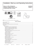
1
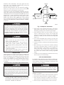
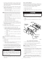
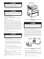
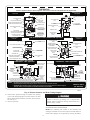
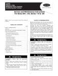
58MVP
Deluxe 4-Way Multipoise Variable-Capacity
Direct-Vent Condensing Gas Furnace
Visit www.carrier.com
Service and Maintenance Instructions
For Sizes 040–120, Series 140 and 150
NOTE: Read the entire instruction manual before starting the
installation.
This symbol → indicates a change since the last issue.
•••••
U L T R
A
G A S
®
•••••
H I G H
•••••
E F F I C
I E N C Y
F U R N
A N C E
A93040
TABLE OF CONTENTS
SAFETY CONSIDERATIONS .....................................................1
Introduction ....................................................................................2
ELECTROSTATIC DISCHARGE (ESD) PRECAUTIONS........2
TROUBLESHOOTING ...............................................................10
Fig. 1—Multipoise Furnace in Upflow Orientation
EFFICIENCY
RATING
CERTIFIED
rr
ier
Cor pora
ti
on
WIRING DIAGRAMS.................................................................10
A92496
Ca
CARE AND MAINTENANCE.....................................................2
Cleaning and/or Replacing Air Filter.......................................3
Blower Motor and Wheel Maintenance...................................3
Cleaning Burners ......................................................................4
Cleaning Heat Exchangers........................................................5
Flushing Collector Box and Drainage
System ............................................................................................7
Servicing Hot Surface Ignitor ..................................................7
Electrical Controls and Wiring.................................................8
Checking Heat Tape Operation
(If Applicable) ................................................................................8
Winterizing................................................................................9
®
IR
I
I
Follow all safety codes. In the United States, follow all safety
codes including the National Fuel Gas Code (NFGC) NFPA
54-1999/ANSI Z223.1-1999 and the Installation Standards, Warm
REG
Untrained personnel can perform basic maintenance functions
such as cleaning and replacing air filters. All other operations must
be performed by trained service personnel. When working on
heating equipment, observe precautions in the literature, on tags,
and on labels attached to or shipped with the unit and other safety
precautions that may apply.
ST
SO
M
CERTIFIED
SAFETY CONSIDERATIONS
Installing and servicing heating equipment can be hazardous due to
gas and electrical components. Only trained and qualified personnel should install, repair, or service heating equipment.
E R E D F8 3
900
1 #A28
REGISTERED QUALITY SYSTEM
Air Heating and Air Conditioning Systems (NFPA 90B)
ANSI/NFPA 90B. In Canada, refer to the CAN/CGA-B/49.1- and
.2-M95 National Standard of Canada, Natural Gas and Propane
Manufacturer reserves the right to discontinue, or change at any time, specifications or designs without notice and without incurring obligations.
Book 1 4
PC 101
Catalog No. 535-795
Printed in U.S.A.
Form 58MVP–9SM
Pg 1
10-00
Replaces: 58MVP-7SM
Tab 6a 8a
Installation Codes (NSCNGPIC). Wear safety glasses and work
gloves. Have a fire extinguisher available during start-up and
adjustment procedures and service calls.
AIRFLOW
Recognize safety information. This is the safety-alert symbol .
When you see this symbol on the unit and in instructions or
manuals, be alert to the potential for personal injury.
UPFLOW
Understand the signal words DANGER, WARNING, and CAUTION. These words are used with the safety-alert symbol. DANGER identifies the most serious hazards which will result in severe
personal injury or death. WARNING signifies hazards which
could result in personal injury or death. CAUTION is used to
identify unsafe practices which would result in minor personal
injury or product and property damage. NOTE is used to highlight
suggestions which will result in enhanced installation, reliability,
or operation.
HORIZONTAL
LEFT
HORIZONTAL
RIGHT
DOWNFLOW
AIRFLOW
AIRFLOW
AIRFLOW
A93041
The ability to properly perform maintenance on this equipment requires certain expertise, mechanical skills, tools, and
equipment. If you do not possess these, do not attempt to
perform any maintenance on this equipment other than those
procedures recommended in the User’s Manual. FAILURE
TO FOLLOW THIS WARNING COULD RESULT IN
POSSIBLE DAMAGE TO THIS EQUIPMENT, SERIOUS
PERSONAL INJURY, OR DEATH.
Fig. 2—Multipoise Orientation
2. Firmly touch a clean, unpainted, metal surface of the furnace
chassis which is close to the control. Tools held in a person’s
hand during grounding will be satisfactorily discharged.
3. After touching the chassis you may proceed to service the
control or connecting wires as long as you do nothing that
recharges your body with static electricity (for example; DO
NOT move or shuffle your feet, DO NOT touch ungrounded
objects, etc.).
Never store anything on, near, or in contact with the furnace,
such as:
1. Spray or aerosol cans, rags, brooms, dust mops, vacuum
cleaners, or other cleaning tools.
2. Soap powders, bleaches, waxes or other cleaning compounds, plastic or plastic containers, gasoline, kerosene,
cigarette lighter fluid, dry cleaning fluids, or other volatile
fluids.
3. Paint thinners and other painting compounds, paper bags,
or other paper products.
Failure to follow this warning can cause corrosion of the
heat exchanger, fire, personal injury, or death.
4. If you touch ungrounded objects (recharge your body with
static electricity), firmly touch furnace again before touching
control or wires.
5. Use this procedure for installed and uninstalled (ungrounded)
furnaces.
6. Before removing a new control from its container, discharge
your body’s electrostatic charge to ground to protect the
control from damage. If the control is to be installed in a
furnace, follow items 1 through 5 before bringing the control
or yourself into contact with the furnace. Put all used AND
new controls into containers before touching ungrounded
objects.
INTRODUCTION
These instructions are written as if the furnace is installed in an
upflow application. An upflow furnace application is where the
blower is located below the combustion and controls section of the
furnace, and conditioned air is discharged upward. Since this
furnace can be installed in any of the 4 positions shown in Fig. 2,
you may need to revise your orientation to component location
accordingly.
7. An ESD service kit (available from commercial sources) may
also be used to prevent ESD damage.
CARE AND MAINTENANCE
For continuing high performance and to minimize possible equipment failure, it is essential that maintenance be performed annually
on this equipment. Consult your local dealer for maintenance and
maintenance contract availability.
ELECTROSTATIC DISCHARGE (ESD) PRECAUTIONS
Turn off the gas and electrical supplies to the unit before
performing any maintenance or service. Follow the operating
instructions on the label attached to the furnace. Failure to
follow this warning could result in personal injury or death.
Electrostatic discharge can affect electronic components.
Take precautions during furnace installation and servicing to
protect the furnace electronic control. Precautions will prevent electrostatic discharges from personnel and hand tools
which are held during the procedure. These precautions will
help to avoid exposing the control to electrostatic discharge
by putting the furnace, the control, and the person at the same
electrostatic potential.
The minimum maintenance that should be performed on this
equipment is as follows:
1. Check and clean or replace air filter each month as required.
2. Check blower motor and wheel for cleanliness annually.
1. Disconnect all power to the furnace. DO NOT TOUCH THE
CONTROL OR ANY WIRE CONNECTED TO THE CONTROL PRIOR TO DISCHARGING YOUR BODY’S ELECTROSTATIC CHARGE TO GROUND.
3. Check electrical connections for tightness and controls for
proper operation each heating season. Service as necessary.
4. Check for proper condensate drainage. Clean as necessary.
2
5. Check for blockages in combustion-air and vent pipes annually.
WASHABLE
FILTER
IN FURNACE
6. Check burners for cleanliness annually.
FILTER
RETAINER
Personal injury could result from sharp metal edges, etc. Use
care when removing parts.
Step 1—Cleaning and/or Replacing Air Filter
The air filter arrangement may vary depending on the application
or orientation.
WASHABLE FILTER OR
DISPOSABLE MEDIA
FILTER IN FILTER CABINET
Never operate unit without a filter or with the blower access
panel removed. Failure to follow this warning could result in
a fire or personal injury.
A00233
NOTE: If the filter has an airflow direction arrow, the arrow must
point toward the blower.
Fig. 4—Filter Installed for Side Inlet
4. Slide filter out of furnace.
To clean or replace filters, proceed as follows:
→ If filter is installed in filter cabinet adjacent to furnace:
5. Furnaces are equipped with permanent, washable filter(s).
Clean filter by spraying cold tap water through filter in
opposite direction of airflow.
1. Turn off electrical supply to furnace.
2. Remove filter cabinet door.
6. Rinse filter and let dry. Oiling or coating filter is not
recommended.
3. Slide filter out of cabinet.
4. If equipped with permanent, washable filter, clean filter by
spraying cold tap water through filter in opposite direction of
airflow. Rinse filter and let dry. Oiling or coating of the filter
is not recommended.
7. Slide filter into furnace.
8. Recapture filter retaining wire.
9. Replace blower access panel and main furnace door.
5. If equipped with factory specified disposable media filter,
replace only with media filter having the same part number
and size.
10. Turn on electrical supply to furnace.
6. Slide filter into cabinet.
To ensure long life, economy, and high efficiency, clean accumulated dirt and grease from blower wheel and motor annually.
Step 2—Blower Motor and Wheel Maintenance
7. Replace filter cabinet door.
The inducer and blower motors are pre-lubricated and require no
additional lubrication. These motors can be identified by the
absence of oil ports on each end of the motor.
8. Turn on electrical supply to furnace.
If filter is installed in furnace blower compartment:
1. Turn off electrical supply to furnace.
The following items should be performed by a qualified service
technician.
2. Remove main furnace door and blower access panel.
3. Release filter retainer wire. (See Figs. 3 and 4.)
Clean blower motor and wheel as follows:
1. Turn off electrical supply to furnace.
2. Remove main furnace door and blower access panel.
3. Disconnect wires
a. Disconnect motor wiring harness plug on blower housing.
b. Disconnect auxiliary limit switch leads at switch.
WASHABLE
FILTER
c. Disconnect field thermostat connections depending on their
length and routing.
4. Position control box, transformer, and door switch assembly to
right side of furnace casing.
FILTER
SUPPORT
5. If condensate trap is located in left- or right-hand side of
furnace casing, proceed to item 6. Otherwise remove trap and
tubing as described below:
FILTER
RETAINER
a. Disconnect field drain connection from condensate trap.
WASHABLE FILTER OR
DISPOSABLE MEDIA FILTER
IN FILTER CABINET
b. Disconnect drain and relief port tubes from condensate
trap.
c. Remove condensate trap from blower shelf.
A00232
6. Remove screws securing blower assembly to blower shelf and
slide blower assembly out of furnace.
Fig. 3—Bottom Filter Arrangement
3
Step 3—Cleaning Burners
7. Clean blower wheel and motor by using a vacuum with soft
brush attachment. Be careful not to disturb balance weights
(clips) on blower wheel vanes. Do not bend wheel or blades as
balance will be affected.
The following items should be performed by a qualified service
technician. If the burners develop an accumulation of light dirt or
dust, they may be cleaned by using the following procedure:
8. If greasy residue is present on blower wheel, remove wheel
from the blower housing and wash it with an appropriate
degreaser. To remove wheel:
1. Turn off gas and electrical supplies to furnace.
2. Remove main furnace door.
3. Remove burner box cover.
a. Mark blower wheel location on shaft before disassembly to
ensure proper reassembly.
4. Using backup wrench, disconnect gas supply pipe from gas
valve.
b. Loosen setscrew holding blower wheel on motor shaft.
NOTE: Mark blower mounting arms and blower housing so each
arm is positioned at the same hole location during reassembly.
c. Mark blower wheel orientation and cutoff plate location to
ensure proper reassembly.
Label all wires prior to disconnection when servicing controls. Wiring errors can cause improper and dangerous
operation.
d. Remove screws securing cutoff plate and remove cutoff
plate from housing.
5. Remove wires from gas valve. Note location for reassembly.
e. Remove bolts holding motor mounts to blower housing and
slide motor and mounts out of housing.
6. Remove burner box pressure tube from gas valve regulator
fitting.
f. Remove blower wheel from housing.
7. Remove screws that secure manifold to burner box. (See Fig.
5.)
g. Clean wheel per instructions on degreaser cleaner.
CELL
PANEL
9. Reassemble motor and blower wheel by reversing items 8b
through 8f. Ensure wheel is positioned for proper rotation. Be
sure to attach ground wire.
MANIFOLD
MOUNTING
SCREW
10. Reinstall blower assembly in furnace.
11. Reinstall condensate trap and tubing if previously removed.
a. Reinstall condensate trap in hole in blower shelf.
b. Connect condensate trap drain tubes. See Fig. 8 or tubing
diagram on main furnace door for proper tube location.
(1.) Connect 1 tube (blue or blue and white striped) from
collector box.
(2.) Connect 1 tube (violet or unmarked) from inducer
housing.
(3.) Connect 1 tube (relief port, green or pink) from
collector box.
MANIFOLD
c. Connect field drain to condensate trap.
GAS VALVE
REGULATOR
FITTING
NOTE: Ensure tubes are not kinked or pinched, as this will affect
operation.
GAS VALVE
12. Reinstall control box, transformer, and door switch assembly
on blower shelf.
A96304
Fig. 5—Burner Box Assembly
13. Reconnect wires.
a. Refer to furnace wiring diagram and connect motor and
auxiliary limit switch leads. (See Fig. 16.)
8. Remove manifold, orifices, and gas valve as 1 assembly.
9. Remove screws attaching burner assembly in burner box.
b. Connect thermostat leads if previously disconnected.
10. Remove burner assembly from burner box.
NOTE: All burners are attached to burner bracket and can be
removed as 1 assembly.
14. Turn on electrical supply. Manually close blower access panel
door switch. Use a piece of tape to hold switch closed. Check
for proper rotation and speed changes between heating and
cooling by jumpering R to G and R to Y on control center
thermostat terminals. (See Fig. 11.)
11. Clean burners with soft brush and vacuum.
12. Reinstall manifold, orifice, and gas valve assembly in burner
box. Ensure manifold seal grommet is installed properly and
burners fit over orifices.
13. Reconnect wires to gas valve. Refer to furnace wiring diagram
for proper wire location.
Blower access panel door switch opens 115-v power to
control center. No component operation can occur. Caution
must be taken when manually closing this switch for service
purposes. Failure to follow this warning could result in
personal injury or death.
14. Reinstall burner box pressure tube to gas valve regulator
fitting.
15. Reinstall gas supply pipe to gas valve using backup wrench on
gas valve to prevent rotation and improper orientation.
NOTE: Use propane gas resistant pipe dope to prevent gas leaks.
DO NOT use Teflon tape.
15. If furnace is operating properly, release blower access panel
door switch, replace blower access panel, and replace main
furnace door.
4
PRIMARY HX
INLET OPENINGS
Gas valve switch or knob MUST be facing forward or tilted
upward. Failure to follow this warning could result in
property damage, personal injury, or death.
16. Replace burner box cover.
17. Turn on gas and electrical supplies to furnace.
18. Check for gas leaks.
Never use matches, candles, flame, or other sources of
ignition to check for gas leakage. Use a soap-and-water
solution. Failure to follow this warning could result in a fire,
personal injury, or death.
19. Replace main furnace door.
Step 4—Cleaning Heat Exchangers
The following items should be performed by a qualified service
technician.
A96305
Fig. 6—Cleaning Inlet Openings of Primary Heat
Exchangers
PRIMARY HEAT EXCHANGERS
If the heat exchangers get an accumulation of light dirt or dust on
the inside, they may be cleaned by the following procedure:
12. Reverse items 4 through 10 for reassembly.
NOTE: If the heat exchangers get a heavy accumulation of soot
and carbon, both the primary and secondary heat exchangers
should be replaced rather than trying to clean them thoroughly due
to their intricate design. A build-up of soot and carbon indicates
that a problem exists which needs to be corrected, such as
improper adjustment of manifold pressure, insufficient or poor
quality combustion air, improper vent termination, incorrect size
or damaged manifold orifice(s), improper gas, or a restricted heat
exchanger (primary or secondary). Action must be taken to correct
the problem.
The ground wire from the gas valve MUST be attached to the
burner box attachment screw. Failure to attach this ground
wire to an adequate casing ground will cause the furnace
control to lock out.
NOTE: Be sure burner box gasket is installed between burner box
and cell panel. If gasket is damaged, replace it.
NOTE: Inspect combustion-air intake housing. If foamed gasket
was removed, check for any damage. If gasket is damaged in any
way, it must be repaired. To repair, remove damaged gasket
section, apply sealant releasing agent such as PAM cooking spray
or equivalent (must not contain corn or canola oil, aromatic or
halogenated hydrocarbons or inadequate seal may occur) to burner
box and apply a small bead of G.E. RTV 162, G.E. RTV 6702, or
Dow-Corning RTV 738 sealant to edge of combustion-air intake
housing. (See Fig. 7.)
1. Turn off gas and electrical supplies to furnace.
2. Remove main furnace door.
Label all wires prior to disconnection when servicing controls. Wiring errors can cause improper and hazardous operation.
3. Disconnect wires or connectors to rollout switch, gas valve,
ignitor, and flame sensor.
4. Disconnect combustion-air intake pipe from intake housing.
5. Remove the pressure switch tube from intake housing.
RTV
6. Remove screws attaching intake housing to burner box, and
rotate intake housing away from burner box for removal.
7. Using backup wrench, disconnect gas supply pipe from gas
valve.
PAM
8. Disconnect pressure tubing from gas valve.
9. Remove 2 screws attaching top filler panel and rotate upwards
to gain access to screws attaching burner box to cell panel.
A93087
10. Remove screws attaching burner box to cell panel. (See Fig.
5.)
Fig. 7—Combustion-Air Intake Housing Gasket
Repair
NOTE: Burner box cover, manifold, gas valve, and burner
assembly should be removed as 1 assembly.
13. Refer to furnace wiring diagram and reconnect wires to rollout
switch, gas valve, ignitor, and flame sensor.
11. Clean heat exchanger openings with a vacuum and a soft
brush. (See Fig. 6.)
14. Reconnect pressure switch tubes to gas valve and intake
housing. Refer to tube routing label on main furnace door for
proper tube location. (See Fig. 8.) Be sure tubes are not
kinked.
NOTE: After cleaning, inspect the heat exchangers to ensure they
are free of all foreign objects that may restrict flow of combustion
products.
15. Turn on gas and electrical supplies to furnace.
5
TUBE ROUTING
Furnace is shipped from factory in upflow configuration. Pressure tube and drain tube routing MUST match the diagrams below.
Condensate Trap; Factory Installed
in Blower Shelf
Tube location when used in UPFLOW application
Condensate Trap on LEFT
Side Optional
BURNER ENCLOSURE PRESSURE
REFERENCE TUBE ASSEMBLY
(Blower access panel removed)
BURNER ENCLOSURE PRESSURE
REFERENCE TUBE ASSEMBLY
CAP
CAP
COLLECTOR BOX TUBE
(PINK)
PLUG
COLLECTOR BOX TUBE
(PINK)
COLLECTOR BOX
DRAIN TUBE
(BLUE & WHITE STRIPED)
COLLECTOR BOX TUBE (GREEN)
INDUCER HOUSING (MOLDED) DRAIN TUBE
(BEHIND COLLECTOR BOX DRAIN TUBE)
PLUG
COLLECTOR BOX TUBE
(GREEN)
COLLECTOR BOX
DRAIN TUBE
(BLUE & WHITE STRIPED)
CONDENSATE TRAP
COLLECTOR BOX DRAIN TUBE
(BLUE)
COLLECTOR BOX DRAIN TUBE
(BLUE)
FIELD-INSTALLED
FACTORY-SUPPLIED DRAIN
TUBE COUPLING (RIGHT
DRAIN OPTION)
FIELD-INSTALLED
FACTORY-SUPPLIED DRAIN TUBE
COUPLING (LEFT DRAIN OPTION)
FIELD-INSTALLED FACTORYSUPPLIED DRAIN TUBE
Condensate Trap on
LEFT Side
CONDENSATE TRAP
FIELD-INSTALLED
FACTORY-SUPPLIED
1/2-IN. CPVC STREET
ELBOWS (2) FOR LEFT
DRAIN OPTION
INDUCER HOUSING
DRAIN TUBE
(VIOLET)
Condensate Trap on
RIGHT Side
Tube location when used in DOWNFLOW application
COLLECTOR BOX TUBE
(GREEN)
COLLECTOR BOX DRAIN TUBE
(BLUE)
CAP
CAP
BURNER ENCLOSURE
PRESSURE REFERENCE
TUBE ASSEMBLY
COLLECTOR BOX TUBE (GREEN)
COLLECTOR BOX DRAIN TUBE
(BLUE & WHITE STRIPED)
COLLECTOR BOX DRAIN TUBE
(BLUE)
COLLECTOR BOX TUBE
(PINK)
COLLECTOR BOX DRAIN TUBE
(BLUE & WHITE STRIPED)
PLUG
COLLECTOR BOX
EXTENSION TUBE
COLLECTOR BOX
EXTENSION TUBE
INDUCER HOUSING
DRAIN TUBE
(VIOLET)
PLUG
COLLECTOR BOX EXTENSION TUBE
CONDENSATE TRAP
COLLECTOR BOX EXTENSION
DRAIN TUBE
DRAIN TUBES ROUTED IN
FRONT OF GAS VALVE
INDUCER HOUSING DRAIN TUBE (VIOLET)
GAS VALVE
Tube location when used on
HORIZONTAL - RIGHT application
Tube location when used on
HORIZONTAL - LEFT application
COLLECTOR BOX DRAIN TUBE
(BLUE & WHITE STRIPED)
PLUG
CAP
COLLECTOR BOX DRAIN TUBE (BLUE)
PLUG
COLLECTOR BOX TUBE (PINK)
AUXILIARY "J" BOX
RELOCATED HERE
COLLECTOR
BOX TUBE
(GREEN)
BURNER
ENCLOSURE
PRESSURE
REFERENCE TUBE
ASSEMBLY
BURNER
ENCLOSURE
PRESSURE
REFERENCE
TUBE ASSEMBLY
CAP
COLLECTOR BOX
EXTENSION TUBE
CONDENSATE TRAP
COLLECTOR BOX EXTENSION DRAIN TUBE
CONDENSATE TRAP
DRAIN TUBE
COUPLING
COLLECTOR BOX TUBE
(PINK)
BURNER ENCLOSURE PRESSURE
REFERENCE TUBE ASSEMBLY
DRAIN TUBE
COUPLING
COLLECTOR BOX TUBE (PINK) RELOCATE TUBE BETWEEN BLOWER SHELF AND
INDUCER HOUSING FOR 040,060, AND 080 HEATING INPUT FURNACES
INDUCER HOUSING
DRAIN TUBE
(VIOLET)
COLLECTOR BOX
EXTENSION TUBE
COLLECTOR BOX TUBE (GREEN)
COLLECTOR BOX
DRAIN TUBE (BLUE)
CONDENSATE TRAP
COLLECTOR BOX DRAIN TUBE
(BLUE AND WHITE STRIPED)
INDUCER HOUSING DRAIN TUBE (VIOLET)
NOTE: 1. All tubing must be connected securely and routed to avoid kinks and traps.
2. Pressure tubing must always slope away from pressure switch to collector box connection as shown.
3. HORIZONTAL-LEFT installations require the collector box pressure tube to be relocated between the inducer housing and
the blower shelf to prevent a trap.Refer to the Installation Instructions for further details.
325400-201 REV. C
(LIT - BOTTOM)
A00351
Fig. 8—Furnace Pressure and Drain Tubing Diagram
16. Check furnace operation through 2 complete heat operating
cycles. Look through sight glass in burner enclosure to check
burners. Burner flames should be clear blue, almost transparent. (See Fig. 9.)
17. Check for gas leaks.
Never use matches, candles, flame, or other sources of
ignition to check for gas leakage. Use a soap-and-water
solution. Failure to follow this warning could result in a fire,
personal injury, or death.
18. Replace main furnace door.
SECONDARY HEAT EXCHANGERS
NOTE: The condensing side (inside) of the secondary heat
exchangers CANNOT be serviced or inspected. A small number of
bottom outlet openings can be inspected by removing the inducer
6
,,
NOTE: Ensure the drain tube disconnected from the inducer
housing is higher than the collector box opening or water will flow
out tube.
BURNER FLAME
BURNER
9. Inspect inside area of collector box for any pieces of foreign
materials and remove if present.
DO NOT use wire brush or other sharp object to inspect or
dislodge materials in secondary heat exchangers as failure of
the secondary heat exchanger will occur. Flush with water
only.
10. Reassemble inducer assembly by reversing items 5-7. Tighten
the vent coupling clamp screw(s) to 15 in.-lb of torque.
NOTE: If seal between the inducer housing and the collector box
is damaged in any way, it must be repaired. To repair, apply
sealant releasing agent such as PAM cooking spray or equivalent
(must not contain corn or canola oil, aromatic or halogenated
hydrocarbons or inadequate seal may occur) to inducer housing.
(See Fig. 10.) Apply a small bead of G.E. RTV 162, G.E. RTV
6702, or Dow-Corning RTV 738 sealant to groove in collector
box.
MANIFOLD
A89020
Fig. 9—Burner Flame
11. Refer to furnace wiring diagram and reconnect wires to
inducer motor and pressure switches or connectors.
PAM
12. Reconnect pressure tubes to pressure switches. See diagram
on main furnace door for proper location of tubes. Be sure
tubes are not kinked. (See Fig. 8.)
RTV
13. Turn on gas and electrical supplies to furnace.
14. Check furnace operation through 2 complete heat operating
cycles. Check area below inducer housing, vent pipe, and
condensate trap to ensure no condensate leaks occur. If leaks
are found, correct the problem.
15. Check for gas leaks.
Never use matches, candles, flame, or other sources of
ignition to check for gas leakage. Use a soap-and-water
solution. Failure to follow this warning could result in a fire,
personal injury, or death.
A93081
16. Replace main furnace door.
Step 6—Servicing Hot Surface Ignitor
Fig. 10—Gasket on Collector Box
The ignitor does NOT require annual inspection. Check ignitor
resistance before removal.
assembly. See Flushing Collector Box and Drainage System
section for details on removing inducer assembly.
1. Turn off gas and electrical supplies to furnace.
2. Remove main furnace door.
Step 5—Flushing Collector Box and Drainage
System
3. Disconnect ignitor wire connection.
4. Check ignitor resistance.
1. Turn off gas and electrical supplies to furnace.
2. Remove main furnace door.
a. Using an ohm meter, check resistance across both ignitor
leads in connector.
3. Disconnect inducer motor and pressure switch wires or
connectors.
b. Cold reading should be between 45 ohms and 90 ohms.
c. If ohm reading is higher than 110 ohms, ignitor is cracked
and must be replaced.
4. Disconnect pressure switch tubes.
5. Disconnect vent pipe from inducer housing outlet by loosening coupling clamp on inducer outlet.
5. Remove ignitor assembly.
6. Disconnect drain tube from inducer housing. (See Fig. 8.)
Allow ignitor to cool before removal. Normal operation
temperatures exceed 2000°F.
7. Remove inducer housing assembly by removing 4 bolts
attaching assembly to cell panel.
8. Flush inside of collector box with water until discharge from
condensate trap is clean and runs freely.
a. Do not remove ignitor from bracket while assembly is in
furnace. Using a 1/4 in. nutdriver, remove screw securing
7
Step 7—Electrical Controls and Wiring
bracket and ignitor assembly to bottom of burner box. The
screw in the bracket is always located toward outside of
burner box. The screw may be hidden by inlet box or inlet
pipe, but can be removed without removing either. After
removing screw, slide ignitor and bracket toward outside of
burner box and pull straight out.
There may be more than 1 electrical supply to the unit. Check
accessories and cooling unit for additional electrical supplies.
The electrical ground and polarity for 115-v wiring must be
maintained properly. Refer to Fig. 11 for field wiring information
and to Fig. 15 for unit wiring information.
The ignitor is fragile. DO NOT allow it to hit the side of the
burner box opening while removing or replacing it.
NOTE: If the polarity is not correct, the STATUS LED on the
control center will flash rapidly and prevent the furnace from
operating. The control system also requires an earth ground for
proper operation of the control center and flame sensing.
b. Inspect ignitor for a white area indicating a crack may be
present. If found, replace ignitor.
NOTE: A small crack cannot be seen on a new ignitor. After a
period of operation, a white area will be visible around the crack.
c. If replacement is required, replace ignitor on ignitor bracket
external to furnace to avoid damage as the silicon portion is
very brittle and will easily crack or shatter.
d. To remove ignitor from ignitor bracket, remove screw
holding ignitor ceramic block to bracket and pull ceramic
block out of bracket.
6. To replace ignitor/ignitor assembly, reverse items 5a through
5d.
7. Reconnect ignitor wire connection.
8. Turn on gas and electrical supplies to furnace.
9. Verify ignitor operation by initiating control board self-test
feature or by cycling thermostat.
10. Replace main furnace door.
The 24-v circuit contains an automotive-type, 3-amp fuse located
on the control center. (See Fig. 12.) Any direct shorts of the 24-v
wiring during installation, service, or maintenance will cause this
fuse to blow. If fuse replacement is required, use ONLY a fuse of
identical size.
With power to the unit disconnected, check all electrical connections for tightness. Tighten all screws on electrical connections. If
any smoky or burned connections are found, disassemble the
connection, clean all parts, strip wire, and reassemble properly and
securely.
Reconnect electrical supply to unit and observe unit through 1
complete operating cycle. Electrical controls are difficult to check
without proper instrumentation; if there are any discrepancies in
the operating cycle, contact your dealer and request service.
Step 8—Checking Heat Tape Operation
(If Applicable)
In applications where the ambient temperature around the furnace
is 32°F or lower, freeze protection measures are required. If this
application is where heat tape has been applied, check to ensure it
will operate when low temperatures are present.
FIELD 24-V WIRING
FIELD 115-, 208/230-, 460-V WIRING
FACTORY 24-V WIRING
FACTORY 115-, 208/230-, 460-V WIRING
NOTE 5
W
FIVE
WIRE
C
R
G
Y
THERMOSTAT
TERMINALS
FIELD-SUPPLIED
DISCONNECT
THREE-WIRE
HEATING
ONLY
208/230- OR
460-V
THREE PHASE
W/W1
GND
115-V
SINGLE
PHASE
W2
NOTE
3
GND
R
AUXILIARY
115-V
FIELD-SUPPLIED J-BOX
DISCONNECT
SWITCH
FURNACE
CONTROL
CENTER
208/230-V
SINGLE
PHASE
G
C
GND
NOTE 1
Y/Y2
24-V
TERMINAL
BLOCK
GND
CONDENSING
UNIT
TWO WIRE
NOTES:
1. Connect Y or Y/Y2 terminal as shown for proper cooling operation.
2. Proper polarity must be maintained for 115-v wiring.
3. Use W2 with 2-stage thermostat when zoning.
4. If any of the original wire, as supplied, must be replaced, use
same type or equivalent wire.
5. Some thermostats require a "C" terminal connection as shown.
A98325
Fig. 11—Field Wiring
8
HOT SURFACE
IGNITOR CONNECTOR
EAC-ELECTRONIC AIR
CLEANER TERMINALS
(115-VAC 1 AMP MAX)
MAIN BLOWER
CONTROL WIRE
CONNECTOR
TRANSFORMER
24-V CONNECTORS
W2 COM W/W1 Y/Y2 R
24V
G HUM
115-V
CONNECTORS
PRESSURE SWITCH
CONNECTOR
HUM-HUMIDIFIER
TERMINAL
(24-VAC 0.5 AMP MAX)
24-V THERMOSTAT
TERMINALS
DEHUMIDIFY ENABLE (DE)
DEHUMIDIFIER (DEHUM)
CONNECTOR
3-AMP FUSE
STATUS AND DIAGNOSTIC
LED LIGHTS
AIR CONDITIONING
(A/C) SETUP SWITCH
SETUP SWITCHES
(SW) AND BLOWER
OFF DELAY SETUP
SWITCHES
MODEL PLUG
CONTINUOUS
FAN (CF) SETUP
SWITCHES
COMMUNICATION
CONNECTOR
A99097
Fig. 12— Variable-Capacity Control Center
NOTE: Heat tape, when used, should be wrapped around the
condensate drain trap and drain line. There is no need to use heat
tape within the furnace casing. Most heat tapes are temperature
activated, and it is not practical to verify the actual heating of the
tape. Check the following:
1. Check for signs of physical damage to heat tape such as nicks,
cuts, abrasions, gnawing by animals, etc.
2. Check for discolored heat tape insulation. If any damage or
discolored insulation is evident, replace heat tape.
32°F MINIMUM INSTALLED
AMBIENT OR FREEZE
PROTECTION REQUIRED
3. Check that heat tape power supply circuit is on.
Step 9—Winterizing
Freezing condensate left in the furnace will damage the
equipment.
If the furnace will be off for an extended period of time in a
structure where the temperature will drop to 32°F or below,
winterize as follows:
A93058
If this furnace is installed in an unconditioned space where
the ambient temperatures may be 32°F or lower, freeze
protection measures must be taken.
furnace until it is visible at point where condensate enters open
drain. (See Fig. 14.)
5. Reconnect drain tube to inducer housing.
6. Replace main furnace door.
1. Turn off electrical supply to furnace.
2. Remove main furnace door.
3. Disconnect drain tube from inducer housing. (See Fig. 13.)
4. Insert funnel in drain tube and pour antifreeze, propylene
glycol (RV, swimming pool antifreeze, or equivalent) into
9
Fig. 13—Inducer Housing Drain Tube
A99118
A99119
Fig. 14—Funnel in Drain and Antifreeze Running
Through Trap
Do not use ethylene glycol (Prestone II antifreeze/coolant or
equivalent automotive type). Failure of plastic components
will occur.
Blower access panel door switch opens 115-v power to
control center. No component operation can occur. Caution
must be taken when manually closing this switch for service
purposes. Failure to follow this warning could result in
personal injury or death.
WIRING DIAGRAMS
See figures 11, 12 and 16 for the Deluxe 4-Way Multipoise
Furnace wiring diagrams.
g. LEDs display last fault code to occur first, followed by any
other fault that has occurred in the last 5 “good or proper”
cycles. The remaining faults displayed will be in numerical
order starting from the lowest number first. Only 1 of each
fault code will be displayed, regardless of how many times
the fault has occurred.
TROUBLESHOOTING
For an explanation of fault codes, refer to service label located on
back of main furnace door (See Fig. 15.).
The control center stores all fault codes for a period of 5 “good or
proper” operating cycles, regardless of 115- or 24-v power
interruption.
NOTE: Removing blower access panel opens blower access
panel door switch and terminates 115-v power to control center.
Look into blower access panel sight glass for current LED status.
h. Fault code display will continue and repeat as described
above or until setup switch SW-1 is turned off.
i. Release blower access panel door switch and replace
blower access panel.
1. To retrieve fault code, proceed with the following:
NOTE: NO thermostat signal may be present at control center
and all blower time delay of periods must be completed.
j. Operate furnace through 1 heat cycle to test for proper
operation and check LED status.
k. If furnace is operating properly and LEDs indicate proper
operation, replace main furnace door.
a. Leave 115-v power to furnace turned on.
2. Fault code display can be removed from control’s display
mode by performing the following. This is also called the
“Clean Up Procedure.”
b. Remove main furnace door.
c. Look into blower access panel sight glass for current LED
status.
d. Remove blower access panel.
a. Leave 115-v power to furnace turned on.
e. Turn setup switch SW-1 to ON position. (See Fig. 12 or 16
for location.)
b. Remove main furnace door.
c. Look into blower access panel sight glass for current LED
status.
f. Manually close blower access panel door switch. Use a
piece of tape to hold switch closed.
d. Remove blower access panel.
10
SERVICE
STATUS
LED CODE
RED LED1 ON
RED LED2 ON
YELLOW LED3 ON
GREEN LED4 ON
RED LED2 FLASHING
Furnace is operating in emergency heat.
The microprocessor has malfunctioned. To reset: Put setup switch "SW-1" in the "ON"
position and jumper thermostat terminals "R", "W/W1", and "Y/Y2" simultaneously with
the door switch pushed in and power to the unit "ON". Disconnect jumper and place
setup switch in the "OFF" position. If LED2 reappears replace main control board.
Furnace is operating in high heat.
Furnace is operating in low heat.
Line voltage polarity is reversed.
EACH OF THE FOLLOWING STATUS CODES IS A TWO DIGIT NUMBER WITH THE FIRST DIGIT
DETERMINED BY NUMBER OF FLASHES OF THE YELLOW LED AND THE SECOND DIGIT
DETERMINED BY NUMBER OF FLASHES OF THE GREEN LED.
11 NO FAULT IN RECENT HISTORY DISPLAY - Indicates no faults have occurred within last five cycles.
To read recent fault history put setup switch "SW-1" in the "ON" position. To clear recent fault
history, put setup switch "SW-1" in the "ON" position and jumper thermostat terminals
"R", "W/W1", and "Y/Y2" simultaneously until an "11" is flashed.
12 BLOWER CALIBRATION LOCKOUT - Indicates RPM calculated for low heat was less than 250 RPM
or greater than 1300 RPM on two successive attempts. Auto reset after three hours. Reset
power and refer to fault #44 section.
13 LIMIT SWITCH LOCKOUT - Indicates the occurrence of 10 successive limit trips during high heat
or three successive limit trips during low heat. Auto reset after three hours.
Check for: - Improper or misaligned limit and/or limit shield.
- Improper high or low heat gas input adjustment.
- Stuck high heat solenoid in gas valve.
14 IGNITION LOCKOUT - Control will auto-reset after three hours. Refer to #34.
21 INVALID MODEL SELECTION - Indicates model plug is missing or incorrect. See wiring diagram
for correct connector jumper location.
22 SETUP ERROR - Indicates setup switch "SW-1" or SW-6" is positioned improperly. The following
combinations will cause the fault.
- Thermostat call with "SW-1" "ON".
- Thermostat call with "SW-6" "ON".
-"SW-1" and "SW-6" both "ON" together.
23 INVALID BLOWER AIRFLOW SELECTION - Indicates improper "A/C" or "CF" switch setting. The 042
and 14 units can deliver 1-1/2 to 3-1/2 tons A/C and 600 to 1400 CFM for continuous fan. The
060 and 20 unit can deliver 2 to 5 tons A/C and 800 to 2000 CFM for continuous fan. If code is
flashing unit will default to closest allowable airflow.
24 SECONDARY VOLTAGE FUSE IS OPEN
Check for: - Short circuit in secondary voltage (24V) wiring.
31 HIGH PRESSURE SWITCH FAULT - Indicates high pressure switch is closed at call, or in low heat,
or fails to close after call, or opens in high heat.
Check for: - Plugged condensate drain.
- Water in vent piping, possibly sagging pipe.
- Improper pressure switch wiring or pressure switch tubing connections.
- Failed or "Out-of-Calibration" pressure switches.
32 LOW PRESSURE SWITCH FAULT - Indicates low pressure switch is closed at call, or fails to close
after call, or opens during operation.
Check for: - Plugged condensate drain.
- Water in vent piping, possibly sagging pipe.
- Improper pressure switch wiring or pressure switch tubing connections.
- Failed or "Out-of-Calibration" pressure switches.
33 LIMIT OR FLAME ROLL-OUT SWITCH IS OPEN - Indicates the limit, rollout switch or auxiliary limit
switch is open or the unit is operating in high heat only mode due to two successive low heat
limit trips. Check for: - Improper or misaligned limit and/or limit shield.
- Improper low heat gas input adjustment.
- Stuck high heat solenoid in gas valve.
34 IGNITION PROVING FAULT - Control will try three more times before a lockout #14 occurs.
Check for: - Gas valve defective or gas valve turned "OFF".
- Defective Hot Surface Ignitor
- Manual valve shut-off.
- Low inlet gas pressure
- Green wire MUST be connected to furnace sheet metal.
- Proper flame sense microamps (.5 microamps D.C. minimum, 4.0 - 6.0 nominal HIGH HEAT)
- Inadequate flame carryover or rough ignition.
- Oxide buildup on flame sensor (clean with fine sandpaper.)
41 BLOWER OUTSIDE VALID SPEED RANGE - Indicates the blower is not operating at the calculated
RPM. If this fault occurs in conjunction with fault #44 check wiring to motor otherwise refer to
the trouble-shooting guide.
42 INDUCER OUTSIDE VALID SPEED RANGE - Indicates the inducer is not operating at the
calculated RPM, or has not started within 10 seconds after a call for heat. Check wiring to
motor otherwise refer to the trouble-shooting guide.
43 PRESSURE SWITCH CALIBRATION FAULT - Indicates the low and high pressure switch "make"
points during high heat purge are not within the calibration range.
Check for: - Plugged condensate drain.
- Water in vent piping, possibly sagging pipe.
- Improper pressure switch wiring or pressure switch tubing connections.
- Failed or "Out of Calibration" pressure switches.
44 BLOWER CALIBRATION FAULT - Indicates the calculated blower speed is below 250 or above
1300 RPM. Unit will default to low or high heat mode if possible. If this fault occurs in conjunction
with fault #41 check wiring to motor otherwise refer to the trouble-shooting guide. If this fault
occurs by itself check for undersized ductwork, or excessive static caused by a dirty filter, or
closed registers.
STATUS CODE EXAMPLE
RED LED2
MICROPROCESSOR
MALFUNCTION
RED LED1
EMER HEAT
2
DEHUM
DE
3
FUSE
1 2 3
GREEN LED4
LOW HEAT
1 2 3
OFF
OFF
1 2 3 4 5 6 7 8
OFF
SETUP SW,(SW1-8)
YELLOW LED3
HIGH HEAT
1
W2 COM W/W1 Y/Y2
4
R
G
HUM
24 V
COUNT THE NO.
OF FLASHES
COUNT THE NO.
OF FLASHES
(2) =
(4)
42 FAULT
INDUCER OUTSIDE VALID
SPEED RANGE
COMPONENT TEST
To initiate the component test sequence, shut "OFF" the room thermostat or disconnect the "R"
thermostat lead. Put setup switch "SW-6" in the "ON" position to start the component test sequence.
Once initiated the main board will turn "ON" the inducer motor-low speed, inducer motor-high speed,
hot surface ignitor, blower motor-low speed, and blower motor-high speed for 15-20 seconds each.
When component test is completed one or more of the following codes will flash. Gas Valve and
Humidifier will not be turned on.
CODE
DESCRIPTION
11 Indicates inducer and blower motor tested OK. Visual check of hot surface ignitor required.
22 SETUP ERROR - Same as code 22 above.
41 BLOWER OUTSIDE VALID SPEED RANGE - Indicates blower motor failed test. Check blower, wiring,
and control center.
42 INDUCER OUTSIDE VALID SPEED RANGE - Indicates inducer motor failed test. Check inducer,
wiring and control center.
To repeat component test turn setup switch "SW-6" "OFF" and then back "ON". After component test is
completed put setup switch "SW-6" in the "OFF" position and reconnect the "R" thermostat lead.
320624-101 REV. H
A99108
Fig. 15—Service Label
11
ORN
BRN
YEL
GRN
YEL
ORN
RED
BLU
YEL
VIO
BLK
WHT
GRN/YEL
YEL
1 2 5 4 3
12
GND
GV
GVR
HI
HPS
HSI
HSIR
HUM
HUMR
ILK
IND
JB
LEDS
LGPS
LPS
LS
MTR1
MTR2
PCB
PL1
PL2
PL3
PL4
PL5
PL12
3
16
8
14
6
RED
ORN
VIO
YEL
BLU
PL13
WHT
BLK
WHT
BLK
RED
WHT
10 11
9
WHT
5
L1
L2
B1
B2
YEL
TRAN
C
P1
P2
PL2
RED
7 8
6 5 4
AIR CONDITIONING (ADJUSTABLE TONNAGE)
AUXILIARY LIMIT SWTICH OVERTEMP - MANUAL RESET SPST-(N.C)
CONTINUOUS FAN (ADJUSTABLE CFM)
MAIN MICROPROCESSOR & CIRCUITRY
IGNITION MICROPROCESSOR & CIRCUITRY
DEHUMIDIFY ENABLE - IF DE CONNECTION PROVIDED REMOVE
JUMPER TO ENABLE DEHUM INPUT
DEHUMIDIFICATION CONNECTION (24VAC .02 AMPS)
ELECTRONIC AIR CLEANER CONNECTION (115 VAC 1.5 AMP MAX.)
ELECTRONIC AIR CLEANER CONNECTION (COMMON)
FLAME ROLLOUT SWITCH - MANUAL RESET, SPST-(N.C.)
FLAME PROVING SENSOR ELECTRODE
FUSE, 3 AMP, AUTOMOTIVE BLADE TYPE, FACTORY INSTALLED
FUSE OR CIRCUIT BREAKER CURRENT INTERRUPT DEVICE
(FIELD INSTALLED & SUPPLIED)
EQUIPMENT GROUND
GAS VALVE
GAS VALVE RELAY, DPST-(N.O.)
GAS VALVE HIGH STAGE OPERATOR
HIGH HEAT PRESSURE SWITCH, SPST-(N.O.)
HOT SURFACE IGNITOR (115 VAC)
HOT SURFACE IGNITOR RELAY, SPST-(N.O.)
24VAC HUMIDIFIER CONNECTION (.5 AMP. MAX.)
HUMIDIFIER RELAY, SPST-(N.O.)
BLOWER ACCESS PANEL INTERLOCK SWITCH, SPST-(N.O.)
INDUCTOR (NOTE #7)
JUNCTION BOX
LIGHT EMITTING DIOES FOR STATUS CODES
LOW GAS PRESSURE SWITCH, SPST (N.O.)
LOW HEAT PRESSSURE SWITCH, SPST-(N.O.)
LIMIT SWITCH, AUTO RESET, (N.C.)
MOTOR (ICM) INDUCER
MOTOR (ICM) BLOWER
PRINTED CIRCUIT BOARD
11-CIRCUIT CONNECTOR
4-CIRCUIT PRESSURE SWITCH CONNECTOR
5-CIRCUIT BLOWER MTR CONNECTOR
2-CIRCUIT HSI CONNECTOR
6-CIRCUIT MODEL PLUG
LPS NOTE #11
NO
CPU1
CPU2
PCB
NOTE #5
SW - 4
EMER. HEAT
ORN LGPS
(WHEN
USED)
B1
BLU
OFF
78
OFF
78
OFF
78
OFF
PL11
7
6
RED
BLOWER
OFF-DELAY
SELECTION CHART
78
90
PL13
6
14
8
16
3
5
4
3
2
1
PL3 1 2 3 4 5
BRN
NOTE
#6
MTR1
PL7
D.C.
POWER
SUPPLY
NOTE #11 ORN
12 3 4
HUM
G
R
Y/Y2
W/W1
COM
DE
W2
SEC-1
DEHUM
PL6
PL7
PL9
PL10
PL11
PL12
PL13
SW1
SW2
SW3
SW4
SW5
SW6
SW7-8
TRAN
PL1
C
ORN
BRN
SEC-2
PL3
FUSE
FU1
A/C AND CF
A/C AND CF
SWITCH
SWITCH
24VAC-3A
SELECT. CHART LEDS
SELECT. CHART
POS.
POS.
A/C
CF
A/C
CF
(1-4) 1 2 3 4
1 2 3
12 3
CF
A/C
3
1200
DEFAULTDEFAULT
123
123
TON
CFM
OFF
OFF
123
1 2 3
1-1/2
600
3-1/2
1400
123 45678
SW
TON
CFM
TON
CFM
OFF
OFF
(1-8)
1 2 3
123
2
800
4
1600
TON
CFM
TON
CFM
OFF
OFF
123
1 2 3
2-1/2
1000
5
2000
TON
CFM
TON
CFM
OFF
OFF
3 2 1
PCB
PL6
1
PL5 6 5 4
BLU
HPS
NO
FLT
LOW HEAT
BPH
EMER. HEAT
MZ
COMP. TEST
BLOWER
OFF-DELAY
ORN
RED
BLU
YEL
VIO
BLK
WHT
IND.
NOTE
#7
5
1
DEHUM
EAC-1
EAC-2
FRS
FSE
FU1
FU2
4 5 6
BLK
9 8 7 6 5 4 3 2 1
PL10
PL11 1
T1
T2
2
1 PL4
YEL
ORN
BRN
WHT
PL1
RED
A/C
ALS
CF
CPU1
CPU2
DE
1 2 3
3
GRN / YEL
NOTE #3
RED
BLK
WHT
1.5 AMP
BRN
HI
GRN/YEL
LEGEND
WHT
12
6
4
2
1
10
T1
PL7
BRN
RED
BLU
M
BLK
GRN
YEL
EAC1
EAC2
RED
P
C
MTR2
3
SCHEMATIC DIAGRAM
(NATURAL GAS & PROPANE)
EQUIPMENT GROUND
T2
L1
GND
BLK
ALS
FSE
PL11
2
YEL
1
ILK
FU2
BLK
WHT
BLK
WHT
ILK
1 2 10 4 12 6
LS
GV
MTR1
HSI
PL9
BLU
FRS
TO 115 VAC FIELD DISCONNECT
L2
L1
NOTE #2
L2
FUSED DISCONNECT SWITCH
(WHEN REQ’D)
NOTE #2
JUMPERS
1-4 2-5 3-6
X
X
X X
X
X
X
X X
1RED
2ORN
3VIO
4YEL
5BLU
MODEL
SIZE
042040
042060
042080
060100
060080
060120
IND
NOTE #7
PL11
PL10
PL12
B2
HSIR
SEC.
2
1 PL9
2
1 PL4
135
EAC
SEC.
MTR2
5
4
3
2
1
EAC-1
HSI
EAC-2
P1
180
PL1-9
SEC.
225
FRS
SEC.
3-CIRCUIT COMM. CONNECTOR
12-CIRCUIT INDUCER MTR CONNECTOR
2-CIRCUIT HSI CONNECTOR
9-CIRCUIT BLOWER ADAPTER CONNECTOR
1-CIRCUIT INDUCTOR SPLICE CONNECTOR
5-CIRCUIT BLOWER POWER CONNECTOR
16-CIRCUIT BLOWER CTRL. CONNECTOR
MANUAL SWITCH, FAULT DISPLAY, SPST-(N.O.)
MANUAL SWITCH, LOW HEAT, SPST-(N.O.)
MANUAL SWITCH, BYPASS HUMIDIFIER, SPST-(N.O.)
MANUAL SWITCH, EMERGENCY HEAT, SPST-(N.O.)
MANUAL SWITCH, MULTIPLE ZONE, SPST-(N.O.)
COMPONENT TEST, SPST-(N.O.)
MANUAL SWITCH, BLOWER OFF-DELAY, SPST-(N.O.)
TRANSFORMER - 115VAC/24VAC
DEHUM
HUM
TRAN
NOTE #6
ALS
LS
24VAC
SEC-1
PL1-11
(WHEN USED) DE
G
GVR
D.C. POWER
SUPPLY
Y/Y2
PCB
NOTE #5
P
W2
GV
PL1-2
C
HI
CPU1
NOTE #3
EAC
PL2-2 NOTE #11
HUMR
LGPS
NOTE #11
NO
CPU2
PCB TERMINAL (FACTORY CONNECTED)
GVR
FACTORY WIRING (24 VAC)
FIELD WIRING (115 VAC)
CONDUCTOR ON PCB
FIELD WIRING SCREW TERMINAL
TERMINAL BLOCK - MARKED TERMINAL
FIELD EARTH GROUND
EQUIPMENT GROUND
FIELD SPLICE
PCB TERMINAL (FIELD CONNECTION)
PLUG RECEPTACLE
PL2-1
C
LPS
JUNCTION
HSIR
HPS
NO
PL2-4
COM
PL1-7
M
PL1-10
W/W1
FACTORY WIRING (115 VAC)
SEC-2
HUMR
R
UNMARKED TERMINAL
P2
115VAC
FU1
C
(WHEN USED)
PL1-1
FSE
NOTES:
1.
2.
3.
4.
5.
6.
7.
8.
9.
10.
11.
If any of the original equipment wire is replaced use wire rated for 105°C.
Use only copper wire between the disconnect switch and the furnace junction box (JB).
This wire must be connected to furnace sheet metal for control to prove flame.
Symbols are electrical representation only.
Solid lines, inside circuit board PCB are printed circuit board traces and are not depicted as shown in the legend.
Replace only with a 3 AMP fuse.
Inductor used on all 060 or -20 airflow units.
Blower-on delay, gas heating 60 seconds low heat, 35 seconds high heat, cooling or heat pump 2 seconds..
Blower-off delay, gas heating 90, 135, 180 or 225 seconds, cooling or heat pump 90 seconds.
Ignition-lockout will occur after four consecutive unsuccessful trials-for-ignition. Control will auto-reset after three hours.
Factory connected when LGPS not used.
322296-101 REV. E
Fig. 16—Wiring Diagram
A00350
e. Turn setup switch SW-1 to ON position. (See Fig. 12 or 16
for location.)
(1.) The control center goes through a brief self test. This
self test takes approximately 2 sec to complete. After
door switch is closed, red (microprocessor) LED
briefly comes on. Then green LED comes on for 1 sec,
followed by 1 sec where both the green and yellow
LEDs are on. During this time, the control is checking
itself.
f. Jumper thermostat terminals R, W, and Y on control center.
g. Manually close blower access panel door switch. Use a
piece of tape to hold switch closed.
(2.) Inducer motor operates for 20 sec at low speed,
operates for 20 sec at high speed, then turns off.
Blower access panel door switch opens 115-v power to
control center. No component operation can occur. Caution
must be taken when manually closing this switch for service
purposes. Failure to follow this warning could result in
electrical shock, personal injury, or death.
(3.) Hot surface ignitor is energized for 15 sec, then
de-energized.
(4.) Main blower motor operates for 20 sec at low speed,
operates at high speed for 20 sec, then turns off.
h. h. After fault code 11 flashes for at least 2 times, remove R,
W, and Y jumpers.
(5.) After component operation test is completed, 1 or
more fault codes (11, 22, 41, or 42) will flash. See
service label on back of main furnace door or Fig. 15
for explanation of codes.
i. Turn setup switch SW-1 to OFF position.
j. Release blower access panel door switch and replace
blower access panel.
NOTE: To repeat component test, turn setup switch SW-6 to OFF
and then back to ON.
k. Operate furnace through 1 heat cycle to check for proper
operation and check LED status.
c. After component test, perform the following:
l. If furnace is operating properly and LEDs indicate proper
operation, replace main furnace door.
(1.) Release blower access panel door switch and turn
setup switch SW-6 to OFF position.
3. The control can also assist in troubleshooting by performing a
Component Test. The Component Test will functionally
operate all furnace components, except the gas valve.
(2.) Replace blower access panel.
(3.) Operate furnace through 1 heat cycle to check for
proper operation and check LED status.
a. To initiate Component Test proceed with the following:
(1.) Leave 115-v power to furnace turned on.
(4.) If furnace is operating properly and LEDs indicate
proper operation, replace main furnace door.
(2.) Remove main furnace door.
(3.) Remove blower access panel.
(4.) Turn setup switch SW-6 to ON position.
(5.) Manually close blower access panel door switch. Use
a piece of tape to hold switch closed.
Blower access panel door switch opens 115-v power to
control center. No component operation can occur. Caution
must be taken when manually closing this switch for service
purposes. Failure to follow this warning could result in
electrical shock, personal injury, or death.
b. When items (1) through (5) above have been completed,
the following will occur:
13
14
SERVICE TRAINING
Packaged Service Training programs are an excellent way to increase your
knowledge of the equipment discussed in this manual, including:
• Unit Familiarization
• Maintenance
• Installation Overview
• Operating Sequence
A large selection of product, theory, and skills programs is available, using popular
video-based formats and materials. All include video and/or slides, plus companion
book.
Classroom Service Training plus "hands-on" the products in our labs can mean
increased confidence that really pays dividends in faster troubleshooting, fewer
callbacks. Course descriptions and schedules are in our catalog.
CALL FOR FREE CATALOG 1-800-962-9212
[ ] Packaged Service Training
[ ] Classroom Service Training
A94328
Fig. 16—Wiring Diagram
15
Copyright 2000 CARRIER Corp. • 7310 W. Morris St. • Indianapolis, IN 46231
58mvp9sm
Manufacturer reserves the right to discontinue, or change at any time, specifications or designs without notice and without incurring obligations.
Book 1 4
Tab 6a 8a
PC 101
Catalog No. 535-795
Printed in U.S.A.
Form 58MVP–9SM
Pg 16
10-00
Replaces: 58MVP-7SM