1
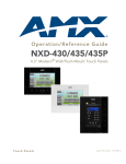
instruction manual
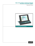
8.5" Color Passive
LCD Touch Panels
(Firmware version G3 or higher)
Tou c h Pa n els an d A cc e ss o r ie s
AMX Limited Warranty and Disclaimer
AMX Corporation warrants its products to be free of defects in material and workmanship under normal use for
three (3) years from the date of purchase from AMX Corporation, with the following exceptions:
•
Electroluminescent and LCD Control Panels are warranted for three (3) years, except for the display and touch
overlay components that are warranted for a period of one (1) year.
•
Disk drive mechanisms, pan/tilt heads, power supplies, MX Series products, and KC Series products are
warranted for a period of one (1) year.
•
Unless otherwise specified, OEM and custom products are warranted for a period of one (1) year.
•
Software is warranted for a period of ninety (90) days.
•
Batteries and incandescent lamps are not covered under the warranty.
This warranty extends only to products purchased directly from AMX Corporation or an Authorized AMX Dealer.
AMX Corporation is not liable for any damages caused by its products or for the failure of its products to perform.
This includes any lost profits, lost savings, incidental damages, or consequential damages. AMX Corporation is not
liable for any claim made by a third party or by an AMX Dealer for a third party.
This limitation of liability applies whether damages are sought, or a claim is made, under this warranty or as a tort
claim (including negligence and strict product liability), a contract claim, or any other claim. This limitation of
liability cannot be waived or amended by any person. This limitation of liability will be effective even if AMX
Corporation or an authorized representative of AMX Corporation has been advised of the possibility of any such
damages. This limitation of liability, however, will not apply to claims for personal injury.
Some states do not allow a limitation of how long an implied warranty last. Some states do not allow the limitation or
exclusion of incidental or consequential damages for consumer products. In such states, the limitation or exclusion of
the Limited Warranty may not apply. This Limited Warranty gives the owner specific legal rights. The owner may
also have other rights that vary from state to state. The owner is advised to consult applicable state laws for full
determination of rights.
EXCEPT AS EXPRESSLY SET FORTH IN THIS WARRANTY, AMX CORPORATION MAKES NO
OTHER WARRANTIES, EXPRESSED OR IMPLIED, INCLUDING ANY IMPLIED WARRANTIES OF
MERCHANTABILITY OR FITNESS FOR A PARTICULAR PURPOSE. AMX CORPORATION
EXPRESSLY DISCLAIMS ALL WARRANTIES NOT STATED IN THIS LIMITED WARRANTY. ANY
IMPLIED WARRANTIES THAT MAY BE IMPOSED BY LAW ARE LIMITED TO THE TERMS OF THIS
LIMITED WARRANTY.
Table of Contents
Table of Contents
Product Information .................................................................................................1
Specifications .................................................................................................................... 1
Cleaning the Touch Overlay.............................................................................................. 2
Installation .................................................................................................................3
Mounting the Touch Panel ................................................................................................ 3
Decor style panels with low-profile Back Boxes....................................................................... 3
Installing touch panels and a BB-TP2 Back Box (solid surface) .............................................. 4
Installing touch panels and a BB-TP2 Back Box (plasterboard) .............................................. 6
Rack-mount panel (AXM-CP/PB)............................................................................................. 8
Wiring the Touch Panel ..................................................................................................... 8
Preparing captive wires............................................................................................................ 8
Wiring guidelines...................................................................................................................... 9
Using AXlink for data and power.............................................................................................. 9
Using the AXlink for data with a 12 VDC power supply ........................................................... 9
Using the (DB-9) RS-232 connector for mouse control or data ............................................. 10
Designing Touch Panel Pages ..............................................................................11
Buttons ............................................................................................................................ 11
Activating Edit Mode........................................................................................................ 12
Setting the Device Base .................................................................................................. 14
Setting the Device Used.................................................................................................. 14
Adding a Page................................................................................................................. 14
Setting the page color ............................................................................................................ 14
Adding a Button............................................................................................................... 15
Resizing a button ................................................................................................................... 15
Defining On-Screen and External Button Properties....................................................... 15
Setting the channel code........................................................................................................ 15
Setting the variable text code................................................................................................. 16
Setting the page flip ............................................................................................................... 16
Setting the button colors for channel-off conditions ............................................................... 17
Adding text, icons, and bitmaps to a button ........................................................................... 17
Using TPDesign3 to Download Bitmaps, Icons, and Fonts............................................. 17
Creating a Bargraph and Joystick ................................................................................... 18
Adding a bargraph or joystick button\..................................................................................... 18
Setting Bargraph and Joystick Properties ....................................................................... 18
Setting the level code............................................................................................................. 18
Programming ..........................................................................................................21
Color Passive-Matrix LCD Touch Panels
i
Table of Contents
System Send_Commands .............................................................................................. 21
Programming Numbers ................................................................................................... 26
Shorthand Send_Commands.......................................................................................... 27
Color Send_Commands.................................................................................................. 31
Variable Text Send_Commands ..................................................................................... 33
Shorthand Variable Text Commands .............................................................................. 36
Button String Commands ................................................................................................ 39
Upgrading the Firmware ........................................................................................ 41
AXT-CP EPROM Replacement....................................................................................... 41
AXM-CP (/PB) and AXD-CP (/PB) EPROM Replacement.............................................. 42
Replacing the Batteries ......................................................................................... 45
AXT-CP Batteries............................................................................................................ 45
AXD-CP (/PB), and AXM-CP/PB Batteries ..................................................................... 46
ii
Color Passive-Matrix LCD Touch Panels
Product Information
Product Information
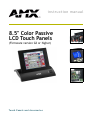
The Color Passive-Matrix touch panels contain an 8.5" (215.90 mm) 256-color passive-matrix
liquid crystal display (LCD). The self-contained enclosures use a microprocessor to control a wide
range of multimedia equipment. Using the TPDesign3 Touch Panel design program, you create
custom pages with buttons, icons, sliders, bargraphs, time displays, logos, and drawings.
8.5" Color Passive-Matrix touch panels include:
!
AXD-CP (Decor-style) and AXD-CP/PB (Decor-style pushbutton)
!
AXT-CP (TiltScreen) and AXT-CP/PB (TiltScreen pushbutton)
!
AXM-CP (Rack-mount) and AXM-CP/PB (Rack-mount pushbutton)
Specifications
The table below lists the specifications for the AXD-CP (/PB), AXT-CP, and AXM-CP (/PB).
Specifications
Dimensions (HWD):
AXD-CP
• 7.50" x 11.25" x 1.77" [low-profile Back Box] (17.48 cm x 28.58 cm x 4.5 cm)
• 7.50" x 11.25" x 2.44" [BB-TP2 Back Box] (17.48 cm x 28.58 cm x 6.2 cm)
AXT-CP
• TiltScreen panel dimensions (HW): 7.10" x 9.11" (18.03 cm x 23.14 cm)
• LCD screen dimensions (HW): 4.80" x 6.40" (12.19 cm x 16.26 cm)
• Base dimensions (WD): 11.46" x 9.46" (29.11 cm x 24.03 cm)
• Adjustable display heights: 3.40" (8.64 cm) fully lowered; 8.50" (21.59 cm) fully
raised.
• Screen Dimensions (HW): 8.5" diagonal view - 4.80" x 6.40" (12.19 cm x 16.26
cm)
AXM-CP
• 6.97" x 19.0" x 1.62" (low-profile Back Box) (17.70 cm x 48.26 cm x 4.11 cm)
• 6.97" x 19.0" x 2.64" (BB-TP2 Back Box) (17.70 cm x 48.26 cm x 6.71 cm)
Weight:
AXD-CP
4.5 lbs. (2.1 kg)
AXT-CP
3.6 lbs. (1.6 kg)
AXM-CP
4.4 lbs. (2.0 kg)
Power
650 mA @ 12 VDC
Display Type
Color passive-matrix 256 color LCD
Screen Res. (HV)
640 x 480 pixels
Memory
1 MB
Rear Panel Connectors:
RS-232
• DB-9 (male) connector for PC data transmission or Microsoft mouse control
AXlink
• 4-pin male bus connector
PWR
• 2-pin male 12 VDC power connector
Color Passive-Matrix LCD Touch Panels
1
Product Information
Specifications (Cont.)
Enclosure:
AXD-CP
Metal sub-plate and bezel with black or white matte finish
AXT-CP
TiltScreen tabletop console; black plastic with matte finish
AXM-CP
19" (48.3 cm) Unimount; metal with black matte finish (4 rack units high)
Accessories Included
• 12 VDC power supply, 1.9 A (110 VAC installations only)
• Low-profile Back Box (AXD-CP and AXM-CP only)
• 4-pin female AXlink bus connector (AXM-CP only)
• 4-pin AXlink data/power connector (AXT-CP only)
Optional Accessories
• Up to 8 pushbuttons per side for the AXD-CP and AXM-CP.
• 9-pin female DB-9 connector (AXD-CP and AXT-CP only.
• PSN2.8 Power Supply
• BB-TP2 Back Box (AXD-CP)
Software
• TPDesign - Windows-based (16-bit) design program (optional for the AXT-CP)
• TPDesign3 - Windows-based (32-bit) design program (optional for the AXT-CP)
AXT-CP Wireless
Options:
TiltScreen
• WAV-PK WavePack
• SMT-PK SmartPack
Options:
Decor-style Panels
• External pushbuttons (AXD-CP (/PB))
• UniMount Back Box (BB-TP2) and sub-plate, bezel security plates
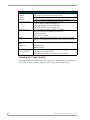
Cleaning the Touch Overlay
You should clean the touch screen overlay after each day’s use. Always use clean cotton cloths, and
a spray bottle of cleaning solution consisting of 50% isopropyl alcohol and 50% water.
2
Color Passive-Matrix LCD Touch Panels
Installation
Installation
Mounting the Touch Panel
The following paragraphs describe mounting the Decor and rack-mount touch panels. TiltScreen
touch panels can be placed on any flat surface.
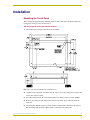
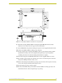
Decor style panels with low-profile Back Boxes
1. Cut out the surface using the dimensions shown in FIG. 1.
FIG. 1 Decor style and low-profile Back Box output dimensions
2. Carefully insert a flat-blade screwdriver into the release slot on the touch panel's faceplate and
remove the engraved overlay.
3. Place the touch panel into the cutout and mark the screw insert positions as shown in FIG. 1.
4. Remove the touch panel and drill four #6-32 insert holes. Then, place a threaded insert into
each hole.
5. Disconnect the AXlink connector from the Central Controller. Then, disconnect the optional
RS-232 wiring from the external RS-232 device connected to the touch panel.
Color Passive-Matrix LCD Touch Panels
3
Installation
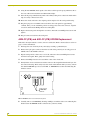
6. Fasten the low-profile Back Box to the surface using the #6-32 machine screws supplied with
the enclosure.
7. Attach the data and power wiring to the touch panel.
8. Test the connection by reconnecting the AXlink connector to the Central Controller and
optional RS-232 wiring to the source equipment. Before continuing, disconnect all connections
until panel installation is complete. Once attached to the Decor style faceplate, the security
screws can’t be replaced without removing the overlay.
9. Fasten the touch panel and low-profile Back Box using the #6-32 machine screws supplied
with the enclosure panel.
10. Place the faceplate onto the bezel. You can also secure the faceplate to the bezel using the four
Phillips flat-head security screws.
11. Insert the engraved overlay back into the bezel.
12. Remove the backing from the adhesive tape strips located on the front of the touch panel; press
the engraved overlay onto the faceplate.
13. Reconnect the AXlink wiring to the Central Controller and RS-232 wiring (optional) to the
external RS-232 device. The touch panel beeps when you apply power.
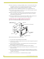
Installing touch panels and a BB-TP2 Back Box (solid surface)
FIG. 2 shows a sample AXD-CP/PB and BB-TP2 Back Box for solid surfaces.
The BB-TP2 can also be mounted to wood or metal studs using the pre-drilled stud mounting holes.
BB-TP2 Unimount
Backbox enclosure
Knockout
Solid surface mounting flanges
AXD-CP/PB
faceplate
Stud mounting
holes
Engraved overlay
FIG. 2 AXD-CP/PB and BB-TP2 Back Box (solid surfaces)
1. Cut out the surface using the dimensions shown in FIG. 3.
4
Color Passive-Matrix LCD Touch Panels
Installation
FIG. 3 Decor style (AXD) and BB-TP2 cutout dimensions
The touch panel must always be installed with the release slot located at the bottom.
2. Carefully insert a flat-blade screwdriver into the release slot on the touch panel’s bezel and
remove the engraved overlay.
3. Lay the touch panel facedown onto a soft cloth and remove the four screws from the lowprofile Back Box. Remove the Back Box and discard.
4. Place the BB-TP2 into the cutout and mark the threaded insert positions as shown in FIG. 3.
5. Remove the BB-TP2 and drill holes (A and B) for the panel (FIG. 3). Then, place #6-32
threaded inserts into the four holes marked 'B' in the cutout dimensions illustration.
6. Disconnect the AXlink connector from the Central Controller. Then, disconnect the optional
RS-232 wiring from the external RS-232 device connected to the touch panel.
7. Remove one or more knockouts to accommodate the wiring as required.
8. Thread the incoming AXlink and RS-232 wiring through the knockouts. Refer to theWiring the
Touch Panel section on page 8 for additional wiring information.
9. Fasten the BB-TP2 to the solid surface using the supplied mounting screws.
10. Connect the AXlink and RS-232 wiring to the touch panel.
Color Passive-Matrix LCD Touch Panels
5
Installation
11. Test the connection by reconnecting the AXlink connector to the Central Controller and the
optional RS-232 wiring to the source equipment. The panel beeps upon power-up. Before
continuing, disconnect all connections until panel installation is complete.
12. Fasten the touch panel to the BB-TP2 using the #6-32 screws supplied with the panel.
13. Place the Decor-style faceplate onto the bezel. You can also secure the faceplate to the bezel
using the four Phillips flat-head security screws.
14. Remove the backing from the adhesive tape strips on the touch panel; press the engraved
overlay onto the faceplate. Once attached to the faceplate, the security screws cannot be
replaced without removing the battery.
15. Reconnect the AXlink wiring to the Central Controller and RS-232 wiring (optional) to the
external RS-232 device. The touch panel will beep when you apply power.
Installing touch panels and a BB-TP2 Back Box (plasterboard)
FIG. 4 shows the AXD-CP/PB and BB-TP2 Back Box for plasterboard.
BB-TP2 Unimount
Backbox enclosure
Knockout
Plasterboard surface mounting flanges
AXD-CP/PB
faceplate
Expansion clips
Engraved overlay
FIG. 4 AXD-CP/PB and BB-TP2 Back Box (plasterboard)
1. Cut out the surface using the dimensions shown in FIG. 5.
2. Carefully insert a flat-blade screwdriver into the release slot on the touch panel's faceplate and
remove the engraved overlay.
3. Lay the touch panel facedown onto a soft cloth and remove the screws from the low-profile
Back Box. Remove the Back Box and discard.
4. Place the BB-TP2 into the cutout and mark the threaded insert positions (FIG. 4).
5. Remove the BB-TP2 and drill four #6-32 insert holes. Then, place a threaded insert (or screw
anchor) into each hole.
6. Disconnect the AXlink connector from the Central Controller that supplies power and data to
the touch panel. Then, disconnect the optional RS-232 wiring from the external RS-232 device
connected to the touch panel.
7. Remove one or more knockouts to accommodate the wiring as required.
6
Color Passive-Matrix LCD Touch Panels
Installation
FIG. 5 Decor style (AXD) and BB-TP2 cutout dimensions for plasterboard
8. Thread the incoming AXlink and RS-232 wiring through the BB-TP2 knockouts. Refer
toWiring the Touch Panel section on page 8 for more information.
9. Fasten the BB-TP2 to the plasterboard using the expansion screws supplied with the enclosure.
10. Connect the AXlink and RS-232 wiring to the touch panel.
11. Test the connection by reconnecting the AXlink connector to the Central Controller and the
optional RS-232 wiring to the source equipment. The panel beeps on power-up. Before
continuing, disconnect all connections until panel installation is complete.
12. Fasten the touch panel to the BB-TP2 with the #6-32 screws supplied with the en-closure.
13. Place the Decor-style faceplate onto the bezel. You can also secure the faceplate to the bezel
using the four Phillips flat-head security screws.
14. Remove the backing from the adhesive tape strips. Once attached to the faceplate, the security
screws cannot be replaced without removing the overlay.
15. Press the engraved overlay onto the faceplate.
16. Reconnect the AXlink wiring to the Central Controller and RS-232 wiring (optional) to the
external RS-232 device. The touch panel beeps on power-up.
Color Passive-Matrix LCD Touch Panels
7
Installation
Rack-mount panel (AXM-CP/PB)
1. Thread the incoming AXlink and optional RS-232 wiring through the opening in the
equipment rack.
2. Disconnect the AXlink connector from the Central Controller and disconnect the optional RS232 connector from the external RS-232 device connected to the touch panel.
3. Insert the touch panel into the equipment rack. Line up the top-left and bottom-right screw
holes and start tightening the #6-32 screws. Then, tighten the bottom-left and top-right screws.
4. Connect the AXlink and RS-232 wiring (optional) to the touch panel. Refer to (DB-9) RS-232
Connector Pinouts table on page 10 for pinout descriptions. The touch panel beeps on
power-up.
Wiring the Touch Panel
The RS-232, AXlink, and PWR (power supply) connectors are located at the rear of the AXT-CP as
shown FIG. 6. The connectors are located on the top-left corner of the rack-mount touch panels as
shown in FIG. 7.
Two-pin power connector
DB-9 connector
Four-pin AXlink connector
FIG. 6 AXT-CP (rear view)
Two-pin power
connector
Four-pin AXlink connector
FIG. 7 AXD-CP (/PB) and AXM-CP (/PB) (top view)
Preparing captive wires
You will need a wire stripper, soldering iron, and flat-blade screwdriver to prepare and connect the
captive wires.
Do not connect power to the touch panel until the wiring is complete. If you are using
a 12 VDC power supply, apply power to the touch panel only after installation is
complete.
1. Strip 0.25 inch of wire insulation off all wires and apply a light coat of solder to the ends using
a soldering iron.
2. Insert each wire into the appropriate opening on the connector according to the wiring
diagrams and connector types described in this subsection.
3. Turn the flat-blade screws clockwise to secure the wire in the connector. Do not over-torque
the screws; doing so can bend the seating pin and damage the connector.
8
Color Passive-Matrix LCD Touch Panels
Installation
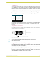
Wiring guidelines
The touch panels require 12 VDC power to operate properly. The Central Controller supplies power
via the AXlink cable or external 12 VDC power supply. The maximum wiring distance between the
Central Controller and touch panel is determined by power consumption, supplied voltage, and the
wire gauge used for the cable. The table below lists wire sizes and the maximum lengths allowable
between the touch panel and Central Controller. The maximum wiring lengths for using AXlink
power are based on a minimum of 13.5 volts available at the Central Controller's power supply.
Refer to theSpecifications section on page 1 for more information on power requirements.
Wiring Guidelines
Wire Size
Maximum Wiring Length
18 AWG
180.57 feet (55.04 m)
20 AWG
114.24 feet (34.82 m)
22 AWG
71.23 feet (21.71 m)
24 AWG
44.90 feet (13.69 m)
If you install the touch panel farther away from the control system than recommended in the Wiring
Guidelines table, connect an external 12 VDC power supply to the 2-pin PWR connector on the
touch panel.
Using AXlink for data and power
Connect the Central Controller's AXlink connector to the AXlink connector on the touch panel for
data and 12 VDC power as shown in FIG. 8.
PWR (+)
AXP
AXM
GND (-)
PWR (+)
AXP
AXM
GND (-)
Central Controller
AXlink connector on the touch panel
FIG. 8 AXlink wiring diagram
If you are using power from AXlink, disconnect the wiring from the Central Controller
before wiring the touch panel.
Using the AXlink for data with a 12 VDC power supply
Connect the Central Controller's AXlink connector to the AXlink connector on the touch panel and
external 12 VDC power supply as shown in FIG. 9.
Use an auxiliary 12 VDC power supply when the distance between the Central Controller and touch
panel exceeds the limits described in Wiring Guidelines table on page 9.
Connect only the GND wire on the AXlink connector when using a 12 VDC power supply. Do not
connect the PWR wire to the AXlink connector's PWR (+) terminal.
Color Passive-Matrix LCD Touch Panels
9
Installation
12 VDC power supply
PWR (+)
GND (-)
PWR (+)
AXP
AXM
GND (-)
PWR (+)
AXP
AXM
GND (-)
Central Controller
AXlink connector on the touch panel
FIG. 9 AXlink and external 12 VDC power supply wiring diagram
Using the (DB-9) RS-232 connector for mouse control or data
The dual-function (DB-9) RS-232 connector supports most standard serial mouse control devices
and RS-232 communication protocols for PC data transmission. Refer to the TPDesign or
TPDesign3 Touch Panel Program instruction manual for data transmission information.
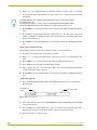
The table below lists (DB-9) RS-232 connector pinouts and FIG. 10 shows the (DB-9) RS-232
connector and power supply wiring diagram.
(DB-9) RS-232 Connector Pinouts
Pin
Signal
Function
1
N/A
Not used
2
RXD
Receive data
3
TXD
Transmit data
4
DTR
Data terminal ready (not used)
5
GND
Signal ground
6
DSR
Data set ready (not used)
7
RTS
Request to send (not used)
8
CTS
Clear to send (not used)
9
N/A
Not used
DB-9 (male)
DB-9 (female)
9
8
9
8
5
4
3
2
1
7
6
7
6
Male
Female
Use connector pins 2, 3, and 5 for data and ground. For some applications, you may need to strap
pins 7 (request to send) and 8 (clear to send) together depending on the PC.
Power connector
+ (PWR)
- (GND)
12 VDC power supply
Optional 7 to 8-pin
connector
5 (GND)
5 (GND)
3 (TXD)
2 (RXD)
3 (TXD)
2 (RXD)
Touch panel
DB-9 connector
Mouse or PC, DB-9 connector
Male
Female
FIG. 10 DB-9 RS-232 connector and power supply wiring diagram
10
Color Passive-Matrix LCD Touch Panels
Designing Touch Panel Pages
Designing Touch Panel Pages
There are two ways to approach creating touch panel pages:
!
TPDesign3 - Refer to the TPDesign3 Touch Panel Program (Version 3. 16 or higher)
Instruction Manual for more information.
!
On-board editor
This document describes basic use of the on-board editor to create pages and buttons. Refer to the
G3 Firmware Design and Reference instruction manual for more detailed firmware information.
Buttons
Standard button types include rectangles and other geometric shapes you can create with the touch
panel editor. Buttons are set with attributes, meaning there is a response from the Central Controller
when you touch the button.
General buttons are part of the default touch panel program and cannot be changed. You use general
buttons to create or revise pages and specify panel communication parameters. Button examples
include selection buttons, information buttons, adjustment buttons, and operation bars. The general
button categories are described in the table below.
General Button Categories
Selection buttons
Selection buttons appear on touch panel pages and set communication parameters.
Information buttons
Information buttons contain serial numbers and firmware version
information. The properties of these buttons cannot be changed.
These buttons have a black fill and yellow text.
Adjustment buttons
You can use the UP and DN buttons to set adjustment buttons. The
adjustment button example sets the baud rate for the connection
from the touch panel to the computer.
Keypad buttons
The keypad button opens a keypad so you can enter a password or
value assignment. All keypad buttons are interactive except for the
entry display.
Decision buttons
Decision buttons appear when an operation has two options and
requires verification before an action is performed.
Color Passive-Matrix LCD Touch Panels
11
Designing Touch Panel Pages
General Button Categories (Cont.)
Status buttons
Status buttons always have a black fill with white letters and have no
functionality except to display information.
Operation bars
Operation bars appear in the place of the Editor bar, after selecting a
button or page edit operation. The operation bar indicates which edit
function is currently active. When an edit operation is selected, it
remains active until you press EXIT.
Touch to Continue buttons
"Touch to Continue" buttons appear when an operation requires user
acknowledgement.
Joystick buttons
Joysticks are vertical and horizontal direction controllers for use with
pan and tilt camera controllers.
Bargraph buttons
Bargraph buttons display a dynamic bargraph (vertical or horizontal).
An example is the Batter level indicator button.
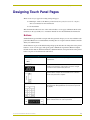
Activating Edit Mode
Before designing touch panel pages and buttons, you must activate EDIT mode. Once activated, use
the EDIT button to enter Edit mode. This mode has options to add and configure touch panels and
buttons. When powering up the touch panel, the first page is the Main page (see FIG. 11). Note that
the Edit button is not available initially.
FIG. 11 Main Page
If you have a pre-programmed panel, you may not see the Main Page.
12
Color Passive-Matrix LCD Touch Panels
Designing Touch Panel Pages
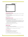
To activate edit mode:
1. Press SETUP in the Main page to open the Setup page (FIG. 12).
FIG. 12 Setup page
2. Press PROTECTED SETUP to open the keypad.
3. Enter 1988 (default password) in the keypad and press ENTER to open Protected Setup page.
If you press ENTER after typing an incorrect password, you are immediately returned to the
previous page.
4. Press EDITOR to enable Edit mode. The EDITOR button is highlighted in the Protected Setup
page when enabled, as shown in FIG. 13.
FIG. 13 Protected Setup page with the active EDITOR button
5. Press EXIT to close the Protected Setup page and return to the Setup page (now in the Edit
mode).
6. Press EXIT again to return to the Main page. The EDIT button appears at the top of the page
indicating that Edit mode is active.
7. Press EDIT to open the Edit bar. The BUTTON and PAGE options, in the Edit bar, (FIG. 14)
are used to design and modify button and page settings.
Color Passive-Matrix LCD Touch Panels
13
Designing Touch Panel Pages
Edit bar
FIG. 14 Main page with Edit bar
Setting the Device Base
Press the DEVICE BASE option, in the Protected Setup page (FIG. 13), to assign a base (starting)
device address to the touch panel.
1. Enter the base address for the touch panel. The base address range is from 1 - 255. Standard
device addresses begin at 128.
2. Press Enter to save.
Setting the Device Used
Use the DEVICE USED option in the Protected Setup page (FIG. 13) to assign a value for the
number of devices being controlled by the touch panel.
1. Press DEVICE USED to open the keypad and enter the panel’s device number from 1 - 4. Each
device number supports up to 255 programmable channel codes. The multiple device settings
allow you to create up to four unique touch panel buttons and/or pages. This value is used to
determine the current device being used by the panel.
2. Enter the number of devices being used by the touch panel.
3. Press Enter to save the value.
Adding a Page
1. Press PAGE on the Edit bar to open the PAGE menu.
2. Press ADD to open the keyboard and enter a name for the new page. Page names can be up to
20 characters.
3. Press EXIT CHANGE to save, close the keyboard, and go to the new page.
Setting the page color
1. Press EDIT to open the Edit bar on the newly created page.
2. Press PAGE on the Edit bar to open the PAGE menu.
3. Press PAGE COLOR to open the black and white color palette.
4. Select a color from the palette; the page automatically changes to the new color.
14
Color Passive-Matrix LCD Touch Panels
Designing Touch Panel Pages
Adding a Button
To add a button to the current page:
1. Press BUTTON on the Edit bar to open the BUTTON menu.
2. Press ADD to open the ADD BUTTON operation bar. On the LCD screen, touch and drag to
create a button. The first touch point is the upper-left corner of the button.
Resizing a button
1. Press BUTTON on the Edit bar to open the BUTTON menu.
2. Press RESIZE. Then, touch any edge of the button and drag. Removing your finger from the
panel saves the button dimensions.
Defining On-Screen and External Button Properties
External pushbuttons are configured with features similar to on-screen buttons. Their functionality
can be set just as any other button on the touch panel.
Use the PROPERTIES option of the BUTTON menu in the Edit bar to set button borders, page
flips, button colors for channel on/off conditions, channel/variable text codes, and string/macro
assignments.
External button properties include only the button type, page flips, channel codes, and string/macro
assignments. Although the Border and Color sections of this page appear, they are of no use to
external pushbuttons since they do not appear on-screen.
Use the following steps to set button properties:
1. Press BUTTON on the Edit bar to open the BUTTON menu options.
2. Press PROPERTIES to open the PROPERTIES operation bar.
3. Press the new button to open the Button Properties page. This page lists the properties for the
active button.
4. Press BUTTON TYPE; this opens the BUTTON TYPE menu.
5. Choose a button type for the selected button to open the associated Button Properties page.
Each button type has its own Button Properties page with settings specific to the button type.
6. Press BORDER to open the BUTTON BORDER pages.
7. Select a border to set for the button and return to the Button Properties page. The BORDER
button changes to show the selected border type.
Setting the channel code
The channel button sets the device and button channel codes.
Channel codes and variable text codes work the same for all button types, including
joysticks, and bargraphs.
1. In the Button Properties page, press DEV to open the keypad and set the touch panel’s device
number.
Color Passive-Matrix LCD Touch Panels
15
Designing Touch Panel Pages
2. Enter 1, 2, 3, or 4 in the keypad. The programming software uses device codes 1 - 4 to identify
the touch panel. Refer to the G3 Firmware Design and Reference instruction manual for more
information.
If DEVICE USED is set to 4 and Base Device Number is 128, the Controller recognizes
bus devices 128 - 131.
The panel will not allow you to enter a device number greater than the DEVICE USED
without first displaying a decision box asking if you accept the new selection or not.
3. Press ENTER to save the device number, close the keypad, and return to the Button Properties
page.
4. Press CHAN to open the keypad and enter a channel value of 1 - 255. The source code uses the
channel code number to identify the button and its programmed operations. The channel code
for non-active buttons is 0.
5. Press ENTER to save the channel number, close the keypad, and return to the Button Properties
page.
Setting the variable text code
The variable text buttons set the device and button channel codes for the buttons.
1. Press DEV to open the keypad and set the device number.
2. Enter 1, 2, 3, or 4 in the keypad. The source code uses device codes 1 - 4 to identify the touch
panel.
3. Press ENTER to save, close the keypad, and return to the Button Properties page.
4. Press CHAN to open a keypad and set the channel number.
5. Enter a channel value of 1 - 255 in the keypad. The source code uses the channel code number
to identify the button and its operations.
6. Press ENTER to save the channel number, close the keypad, and return to the Button Properties
page.
Setting the page flip
1. Press the PAGE FLIP Type button (FIG. 15) in the Button Properties page to open the Page
Flip Type menu.
Page FLIP type
button
Flip to Page button
FIG. 15 Page FLIP Type button
2. Select a Page Flip type. If you select FLIP PREVIOUS in the Page FLIP Type menu, the FLIP
to Page button appears.
3. Press the FLIP to Page button (FIG. 15) to open a list of all the saved touch panel pages. If the
desired page is not present in the menu, check to verify the page has been saved.
4. Select the target page for the page flip.
16
Color Passive-Matrix LCD Touch Panels
Designing Touch Panel Pages
Setting the button colors for channel-off conditions
1. Press any button to open the Button Properties page.
2. Press BORDER under CHANNEL OFF in the Button Properties page. The color palette
appears. Select a color to set as the border.
3. Press the FILL button in the Button Properties page to open the palette. Select a color to set as
the fill.
4. Press the TEXT button to open the palette. Select a color to use for the text.
5. Press EXIT SAVE CHANGE in the Button Properties page to save the new button properties
and return to the current page.
Adding text, icons, and bitmaps to a button
1. Press BUTTON on the Edit bar to open the BUTTON menu.
2. Press TEXT/IMAGE to add text to the button. The TEXT/IMAGE operation bar appears.
3. Press any button to open the Text/Image page.
4. Go through each option and set as desired:
!
TEXT OFF and TEXT ON sets the text for the button's Off and On state.
!
ICON OFF and ICON ON sets the icon for the button's Off and On state.
!
BITMAP OFF and BITMAP ON sets the bitmap for the button's Off and On state.
!
MAKE ON SAME AS OFF sets the On and Off properties the same.
You cannot create or edit buttons with Unicode fonts on the panel. Any use of the
TEXT/IMAGE button to alter or create Unicode font supported buttons must be done
in the TPDesign3 Touch Panel Design Program.
5. Press EXIT SAVE CHANGE to close the Text/Image page and return to the Main page.
Using TPDesign3 to Download Bitmaps, Icons, and Fonts
TPDesign3 allows you to download bitmaps, icons, and fonts into your touch panel from an
existing touch panel program. Touch Panel programs are created in the TPDesign3 software
program. Refer to the TPDesign3 Touch Panel Program (version 3.13 or higher) instruction manual
for more information. Use the Download to Panel button to download a project file.
To download bitmaps, icons and/or fonts from an existing TPDesign3 project file:
1. Launch the TPDesign3 software program and open a project file that contains the desired
bitmaps, icons, and fonts.
2. Select File from the menu bar to open the File menu.
3. In the File menu, click on Download to Panel, this opens the Download to Panel dialog box.
4. Click on the Comm Settings tab to set the communications port, baud rate, and other
communication settings.
5. Then, click the Actions tab to set the communication mode and select which elements of the
project file you want to download to the touch panel.
Color Passive-Matrix LCD Touch Panels
17
Designing Touch Panel Pages
6. In the What To Send area, select one or more of the available options (All Bitmaps, All Icons,
All Fonts).
7. Select the mode of communication with the touch panel (RS-232 and AXlink). Confirm that
the correct panel is selected by verifying the ID values with the Base Address assigned to the
touch panel in the Protected Setup page.
8. After clicking Connect, the Available Panels list appears in the Available Panels field. Click
Begin to start downloading the project file into the panel.
9. After completing the download, the bitmaps, icons and fonts that were downloaded are now
accessible via the BITMAPS, ICONS and FONTS menus.
Creating a Bargraph and Joystick
Bargraphs are level monitors and adjustable level controls. These levels can be configured to
monitor and adjust audio outputs and lighting levels.
Joysticks are vertical and horizontal direction controllers you can use for camera for pan and tilt
control. Before you start, make sure to connect the touch panel to your Controller; otherwise, the
joystick will not work properly.
Adding a bargraph or joystick button\
Create a new button using the ADD operation bar in the BUTTON menu.
1. Press BUTTON in the Edit bar to open the BUTTON menu.
2. Press PROPERTIES in the BUTTON menu to open the PROPERTIES operation bar.
3. Press any button to open the Button Properties page.
4. Press BUTTON TYPE to open the BUTTON TYPE menus. Choose a button type to open its
Button Properties page.
Setting Bargraph and Joystick Properties
Use the Button Properties page to set channel, level, and button colors. Refer to the Setting the
variable text code section on page 16 and the Setting the channel code section on page 15 for
further information. Refer to the Setting the button colors for channel-off conditions section on
page 17 for more information on colors for channel-off conditions.
Setting the level code
Level buttons set the device and number codes for the touch panels.
Joysticks actually use two level numbers. The first is for the X-axis and the second is
for the Y-axis. You only need to specify the first level.
1. Press DEV to open a keypad and set the device number.
2. Enter 1, 2, 3, or 4 in the keypad. The programming software uses device codes
1 - 4 to identify the touch panel.
3. Press ENTER to save the level device number, close the keypad, and return to the Button
Properties page.
18
Color Passive-Matrix LCD Touch Panels
Designing Touch Panel Pages
4. Press NUM to open a keypad and set the level number assigned to the device.
5. Enter a number 1 – 8. Each device can have from 1 – 8 levels except joysticks, where the range
is 1 – 7.
6. Press ENTER to save, close the keypad, and return to the Button Properties page.
Color Passive-Matrix LCD Touch Panels
19
Designing Touch Panel Pages
20
Color Passive-Matrix LCD Touch Panels
Programming
Programming
You can program the touch panel to perform a wide variety of operations using AXCESS
Send_Commands and variable text commands. Use the commands described in this section to
program the touch panel.
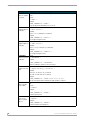
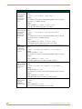
System Send_Commands
System Send_Commands are stored in the Controller and direct the touch panel to perform various
operations.
System Send_Commands
ABEEP
Syntax:
Outputs one panel
"’ABEEP’"
beep even if the
Example:
beep value is set
SEND_COMMAND TP, "’ABEEP’"
to 0 in the Setup
page.
Beeps the panel.
ADBEEP
Syntax:
Outputs a double
"’ADBEEP’"
beep even if the
Example:
double beep value
SEND_COMMAND TP, "’ADBEEP’"
is set to 0 in the
Setup page.
Double beeps the panel.
AKEYB
The keyboard string is set to null during power-up and is stored until power-down.
Opens the touch
panel keyboard
and initializes the
text string entry.
Syntax:
“’AKEYB-<text string>’"
Variables:
text string = 0 - 59 characters
Example:
SEND_COMMAND TP, “’AKEYB-TOUCH HERE’"
Opens the touch panel keyboard with TOUCH HERE in the display.
AKEYP
The keyboard string is set to null during power-up and is stored until power-down for.
Opens the touch
panel keypad and
initializes the
number string
entry.
Syntax:
"’AKEYP-<number string>’"
Variables:
number string = 0 - 9999
Example:
SEND_COMMAND TP,"’AKEYP-1988’"
Opens the touch panel keypad with 1988 in the display.
AKEYR
Syntax:
Closes/opens the
touch panel keyboard/pad.
Example:
"’AKEYR’"
SEND_COMMAND TP,"’AKEYR’"
Closes the keyboard/keypad opened using the ’AKEYB’, ’AKEYP’, or ’PKEYP’ commands.
Color Passive-Matrix LCD Touch Panel
21
Programming
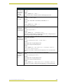
System Send_Commands (Cont.)
BEEP
The Beep button in the Protected Setup page must be set from 1 - 10 for the BEEP comGives an output of mand.
one beep.
Syntax:
"’BEEP’"
Example:
SEND_COMMAND TP,"’BEEP’"
Beeps the panel if the Beep button is not set to 0.
BRIT
Adjusts brightness
of display.
Syntax:
"’BRIT-<level>’"
Variables:
level = 1 - 5 (1 = minimum; 5 = maximum)
Example:
SEND_COMMAND TP,"’BRIT-5’"
Sets to highest brightness level.
CONT
Adjusts brightness
of display.
Syntax:
"’CONT-<level>’"
Variables:
level = 1 - 12 (1 = minimum; 12 = maximum)
Example:
SEND_COMMAND TP,"’CONT-12’"
Sets to highest brightness level.
CALIBRATE
Starts touch panel
calibration.
Syntax:
"’CALIBRATE’"
Example:
SEND_COMMAND TP,"’CALIBRATE’"
Starts the calibration operation on the touch panel.
CLOCK
Sets the time and
date.
Syntax:
"’CLOCK <mm-dd-yy> <hh:mm:ss>’"
Variables:
mm = 01 - 12, dd = 01 - 31, yy = 00 - 99
hh = 00 - 23, mm = 00 - 59, ss = 00 - 59
Example:
SEND_COMMAND TP,"’CLOCK 02-08-98 19:16:00’"
Sets the touch panel’s date to February 8, 1998, and time to 7:16 p.m.
DBEEP
Gives a double
beep output.
This command only works if the Double Beep value in the Protected Setup page is set to
ON.
Syntax:
"’DBEEP’"
Example:
SEND_COMMAND TP,"’DBEEP’"
Double beeps the panel.
MOUSE
Turns on the
Microsoft Serial
Mouse.
Syntax:
"’MOUSE’"
Example:
SEND_COMMAND TP,"’MOUSE’"
Activates the Microsoft Serial Mouse.
22
Color Passive-Matrix LCD Touch Panels
Programming
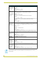
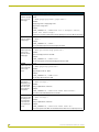
System Send_Commands (Cont.)
PAGE
Syntax:
Flips to page with
specified page
name.
Variables:
"’PAGE-<page name>’"
page name = 1 - 50 ASCII characters
Example:
SEND_COMMAND TP, "’PAGE-MAIN PAGE’"
Flips the touch panel to the page named MAIN PAGE.
PKEYP
Syntax:
Displays asterisks (*) for keypad
entries.
Variables:
"’PKEYP-<number string>’"
number string = 0 - 9999
Example:
SEND_COMMAND TP, "’PKEYP-1988’"
Displays the touch panel keypad with **** instead of 1988.
PPOF
Closes a specific
popup page.
Syntax:
"’PPOF-<page name>’"
Variables:
page name = 1 - 50 ASCII characters
Example:
SEND_COMMAND TP,"’PPOF-Popup Page 1’"
Closes Popup Page 1.
PPON
Opens a specific
popup page.
Syntax:
"’PPON-<page name>’"
Variables:
page name = 1 - 50 ASCII characters
Example:
SEND_COMMAND TP,"’PPON-Popup Page 1’"
Opens Popup Page 1.
QBEEP
Syntax:
Stops all beeps.
"’QBEEP’"
Example:
SEND_COMMAND TP,"’QBEEP’"
Stops all beeps.
RESET
Clears panel status (same as
power up). Saved
data is not
cleared.
SETUP
Goes to the Setup
page.
Syntax:
"’RESET’"
Example:
SEND_COMMAND TP,"’RESET’"
Resets the touch panel.
Syntax:
"’SETUP’"
Example:
SEND_COMMAND TP, "’SETUP’"
Flips the touch panel to the Setup page.
Color Passive-Matrix LCD Touch Panel
23
Programming
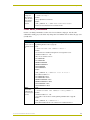
System Send_Commands (Cont.)
SLEEP
Syntax:
Forces the touch
panel to screen
saver mode.
Example:
"’SLEEP’"
SEND_COMMAND TP,"’SLEEP’"
Activates the screen saver mode.
$SC
Sends a serial
port
send_command
within a panel, as
if sent from
Axcess.
Syntax:
"$SC <device offset>,"’<send_command>,<variable
text #>,<data>’""
Variables:
device offset = Device number
variable text # = The variable text number value on the touch panel.
Example:
$SC 1,"’@TXT’,2,’TEXT’"
The string is sends the command to put text on a button with a variable text value of 2. It is
crucial that all the correct ’ and " be used with no spaces after the commas.
Example:
$SC 1,"’SLEEP’"
Sets a touch panel to sleep.
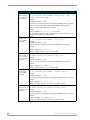
$ST
The command is followed by 1, 2, or 3 ASCII digits.
Sets the power
time-out for
TiltScreen panels.
The entered number is not valid when there is no WAV-PK connected to the TiltScreen panels. The command is sent to the WAV-PK, which then sends it to the panel.
Syntax:
"’$ST <number>’"
Variables:
number = 1 - 255 ASCII characters
Example:
SEND_COMMAND TP, "’$ST 31’"
The number entered is based on the minute increments available within the touch panel
such as 30, 60, 120 minutes. This number will be rounded down to match an increment.
TPAGEOFF
Syntax:
Deactivates page
tracking.
Example:
"’TPAGEOFF’"
SEND_COMMAND TP,"’TPAGEOFF’"
Deactivates the page tracking option.
TPAGEON
See TPAGEON on page 24 for more information.
Activates page
tracking.
WAKE
Syntax:
Deactivates
screen-saver
mode and resets
sleep timer.
Example:
ZAP!
Syntax:
Clears all memory; erases buttons, pages,
drawings, and
symbols.
"’WAKE’"
SEND_COMMAND TP,"’WAKE’"
Deactivates the touch panel screen-saver mode and resets the sleep timer.
"’ZAP!’"
Example:
SEND_COMMAND TP, "’ZAP!’"
Clears all memory and erases all buttons, pages, drawings, and symbols.
Only use the ZAP! command to erase all the saved data in the touch panel; data cannot be recovered
after it is erased.
24
Color Passive-Matrix LCD Touch Panels
Programming
System Send_Commands (Cont.)
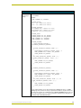
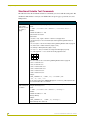
TPAGEON
Activates page
tracking.
Syntax:
"’TPAGEON’"
Example:
SEND_COMMAND TP,’TPAGEON’
DEFINE_DEVICE
TP1 = 128 (*AMX Touch Panel*)
TP2 = 129 (*AMX Touch Panel*)
DEFINE_VARIABLE
TP1_BUFFER[100] (*Buffer for TP1*)
TP2_BUFFER[100] (*Buffer for TP2*)
TRASH[50] (*For Parsing Above*)
DEFINE_START
CREATE_BUFFER TP1,TP1_BUFFER
CREATE_BUFFER TP2,TP2_BUFFER
SEND_COMMAND TP1,'TPAGEON'
SEND_COMMAND TP2,'TPAGEON'
DEFINE_PROGRAM
(* PAGE TRACKING ROUTINE *)
IF(LENGTH_STRING(TP1_BUFFER))
{
IF(FIND_STRING(TP1_BUFFER,'PAGE-',1))
{
TRASH=REMOVE_STRING(TP1_BUFFER,'PAGE-',1)
SEND_COMMAND TP2,"'PAGE-',TP1_BUFFER"
CLEAR_BUFFER TP1_BUFFER
}
IF((FIND_STRING(TP1_BUFFER,'PPON-',1))
OR(FIND_STRING(TP1_BUFFER, 'PPOF-',1)))
{
SEND_COMMAND TP2,TP1_BUFFER
CLEAR_BUFFER TP1_BUFFER
}
}
IF(LENGTH_STRING(TP2_BUFFER))
{
IF(FIND_STRING(TP2_BUFFER,'PAGE-',1))
{
TRASH=REMOVE_STRING(TP2_BUFFER,'PAGE-',1)
SEND_COMMAND TP1,"'PAGE-',TP2_BUFFER"
CLEAR_BUFFER TP2_BUFFER
}
IF((FIND_STRING(TP1_BUFFER,'PPON-',1)) OR
(FIND_STRING(TP1_BUFFER,'PPOF-',1)))
{
SEND_COMMAND TP1,TP2_BUFFER
CLEAR_BUFFER TP2_BUFFER
}
}
(* The command string is sent to the Controller in the ’PAGE-(page name)’ or ’PPON/
PPOF-(page name)’ format. The string is captured in the buffer for one panel and sent to
the other panel. If panels are combined using the DEFINE_COMBINE statement, the routine needs to be written only once, and the command is sent back to the same panel. *)
(* END OF PAGE TRACKING ROUTINE *)
Color Passive-Matrix LCD Touch Panel
25
Programming
Programming Numbers
The following information provides the programming numbers for colors, fonts, and borders
!
Colors can be used to set the colors on buttons, sliders, gauges, and pages. The lowest
color number represents the lightest color-specific display; the highest number represents
the darkest display. For example, 0 represents light red, and 5 is dark red.
Colors and Programming Numbers
!
Color
No.
Color
No.
Red
0-5
Purple
54 - 59
Orange
6 - 11
Magenta
60 - 65
Yellow
12 - 17
Pink
66 - 71
Lime
18 - 23
White
72 - 77
Green
24 - 29
Light Gray
78 - 83
Aqua
30 - 35
Dark Gray
84 - 86
Cyan
36 - 41
Black
87
Royal
42 - 47
Transparent
255
Blue
48 - 53
Font styles are used to program text fonts on buttons, sliders, gauges, and pages. The
programming numbers are assigned consecutively when downloaded to the touch panel.
You must import variable text fonts into a TPDesign3 project file, and download the
project file containing the fonts to the touch panel. The variable fonts are
programming numbers assigned by the touch panel during the download process.
Font Styles and Programming Numbers
!
No.
Font styles
No.
Font styles
1
Extra small
5
Extra large
2
Small
6
Hollow medium
3
Medium
8
Hollow extra large
4
Large
32 - 255
Variable fonts
Border styles can be used to program borders on buttons, sliders, and gauges.
Border Styles and Programming Numbers
26
No.
Border styles
No.
Border styles
0
No border
11
Double shadow
1
No border special
20
3-dimensional rectangle 1
2
Single line
21
3-dimensional rectangle 2
3
Double line
22
3-dimensional round 1
4
Triple line
23
3-dimensional round 2
5
Single rounded
24
3-dimensional neon 1
6
Double rounded
25
3-dimensional neon 2
7
Single raised
26
3-dimensional neon blue
8
Double raised
27
3-dimensional neon green
9
Triple raised
40
Single diamond
10
Double-line two single
41
Double diamond
Color Passive-Matrix LCD Touch Panels
Programming
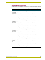
Shorthand Send_Commands
The table below lists the shorthand Send_Commands you can use with touch panels. The shorthand
command data is 1-byte, non-ASCII format except for pages, passwords, text, and bitmap names.
Shorthand Send_Commands
@CBF
This works only if the specified background color is not the same as the current color.
Sets the OFF
feedback border
color to the specified color.
Syntax:
"’@CBF’,<variable text address>,<color_number>"
Variables:
variable text address = 1 - 255
color number = See the Colors and Programming Numbers table on page 26.
Example:
SEND_COMMAND TP,"’@CBF’,1,0"
Sets the OFF feedback border color to Red for the variable text button 1.
@CBN
This works only if the specified background color is not the same as the current color.
Sets the ON feed- Syntax:
back border color
"’@CBN’,<variable text address>,<color_number>
to the specified
Variables:
color.
variable text address = 1 - 255
color number = See the Colors and Programming Numbers table on page 26.
Example:
SEND_COMMAND TP,"’@CBN’,2,78"
Sets the ON feedback border color to Gray for variable text button 2.
@CFF
This only works if the specified background color is not the same as the current color.
Sets the OFF
feedback fill color
to the specified
color.
Syntax:
"’@CFF’,<variable text address>,<color_number>"
Variables:
variable text address = 1 - 255
color number = See the Colors and Programming Numbers table on page 26.
Example:
SEND_COMMAND TP,"’@CFF’,1,72"
Sets the OFF feedback fill color to White for variable text button 1.
@CFN
This only works if the specified background color is not the same as the current color.
Sets the ON feed- Syntax:
back fill color to
"’@CFN’,<variable text address>,<color_number>"
the specified
Variables:
color.
variable text address = 1 - 255
color number = See the Colors and Programming Numbers table on page 26.
Example:
SEND_COMMAND TP,"’@CFN’,1,30"
Sets the ON feedback fill color to Aqua for variable text button 1.
Color Passive-Matrix LCD Touch Panel
27
Programming
Shorthand Send_Commands (Cont.)
@CPG
This only works if the new background color is not the same as the current color.
Sets the page with Syntax:
specified page
"’@CPG’,<color_number>,’<page name>’"
name backVariables:
ground color to
the specified
color number = See the Colors and Programming Numbers table on page 26.
color.
page name = 1 – 50 ASCII characters
Example:
SEND_COMMAND TP,"’@CPG’,87,’Main Page’"
Sets the page title to Main Page, and the color to Black.
@CPP
This only works if the specified background color is not the same as the current color.
Sets the page with Syntax:
specified page
"’@CPP’,<color_number>,’<pop-up page name>’"
name backVariables:
ground color to
the specified
color number = See the Colors and Programming Numbers table on page 26.
color.
pop-up page name = 1 – 50 ASCII characters
Example:
SEND_COMMAND TP,"’@CPP’,54,’Audio Page’"
Sets the popup page title to Audio Page, and the color to Purple.
@CTF
This only works if the specified background color is not the same as the current color.
Sets the OFF
feedback text
color to the specified color.
Syntax:
"’@CTF’,<variable text address>,<color_number>"
Variables:
variable text address = 1 – 255
color number = See the Colors and Programming Numbers table on page 26.
Example:
SEND_COMMAND TP,"’@CTF’,1,48"
Sets the OFF feedback text color to Blue for variable text button 1.
@CTN
This only works if the specified background color is not the same as the current color.
Sets the ON feed- Syntax:
back text color to
"’@CTN’,<variable text address>,<color_number>"
the specified
Variables:
color.
variable text address = 1 – 255
color number = See the Colors and Programming Numbers table on page 26.
Example:
SEND_COMMAND TP,"’@CTN’,1,72"
Sets the ON feedback text color to White for variable text button 1.
@IDF
Syntax:
The touch panel
returns its
MS-DOS file
name in a string.
Example:
"’@IDF’"
SEND_COMMAND TP,"’@IDF’"
The touch panel returns its MS-DOS file name in a string.
28
Color Passive-Matrix LCD Touch Panels
Programming
Shorthand Send_Commands (Cont.)
@IDP
Queries the touch
panel to return a
string with the
TPDesign3
project name.
@MOU
Sets the serial
mouse type.
Syntax:
"’@IDP’"
Example:
SEND_COMMAND TP,"’@IDP’"
The touch panel returns a string that contains its TPDesign3 project name.
Syntax:
"’@MOU’,<touch_type>"
Variables:
touch_type = <Mouse Off> = 0 and <Microsoft Serial Mouse> = 1
Example:
SEND_COMMAND TP,"’@MOU’, 1"
Sets the Microsoft Serial Mouse.
@PPA
If no page is specified, the active page is used.
Removes all
Syntax:
popup pages from
"’@PPA-<page name>’"
a specified page.
Example:
SEND_COMMAND TP, "’@PPA-Main Page’"
If there were several popup pages on ’Main Page’ that are active, sending the previous
command would remove them all from ’Main Page’.
@PPF
Deactivates a
popup page on a
touch panel page.
If a page name is empty the current page is used. If a pop-up page is part of a group, the
whole group is deactivated.
Syntax:
"’@PPF-<popup page name>; <page name>’"
Variables:
popup page name = target popup page name
page name = target touch panel page name
Example:
SEND_COMMAND TP,"’PPF-Laser Disc 2 Transport Control;
Laser Disc Control Page’"
Deactivates the Laser Disc 2 Transport Control popup page on the Laser Disc Control
Page.
@PPK
If a pop-up page is part of a group, the whole group is deactivated.
Deactivates a
popup page on all
touch panel
pages.
Syntax:
"’@PPK-<popup page name>’"
Variables:
popup page name = target popup page name
page name = target touch panel page name
Example:
SEND_COMMAND TP,"’@PPK-Laser Disc 2 Transport Control’"
Deactivates the Laser Disc 2 Transport Control popup page on all touch panel pages.
Color Passive-Matrix LCD Touch Panel
29
Programming
Shorthand Send_Commands (Cont.)
@PPN
If a page name is empty the current page is used.
Activates a popup
page on a touch
panel page.
Syntax:
"’@PPN-<popup page name>;<page name>’"
Variables:
popup page name = Popup page name
page name = Page name
Example:
SEND_COMMAND TP,"’@PPN-Laser Disc 2 Transport Control;
Laser Disc Control Page’"
Activates the Laser Disc 2 Transport Control popup page on the Laser Disc Control Page.
@PPX
Removes all panel
popup pages.
Syntax:
"’@PPX’"
Example:
SEND_COMMAND TP,"’@PPX’"
Closes all popup pages from all of the pages in the panel.
@PRO
Syntax:
Sets the password
"’@PRO-<protected setup password>’"
for the touch
Variables:
panel Protected
protected setup password = 0 - 9999
Setup page.
Example:
SEND_COMMAND TP,"’@PRO-1988’"
Sets the touch panel’s Protected Setup page password to 1988.
@PWD
Syntax:
Sets the password
"’@PWD-<page flip password>’"
for the Page Flip
Variables:
on the touch
page flip password = 0 - 9999
panel.
Example:
SEND_COMMAND TP,"’@PWD-1988’"
Sets the page flip password to 1988.
@SSL
Changes the
Sleep string sent
to the Controller
when the touch
panel activates
sleep mode.
Syntax:
"’@SSL-<string>’"
Variables:
string = alphanumeric characters
Example:
SEND_COMMAND TP,"’@SSL-Touch Panel Deactivated’"
Sends Touch Panel Deactivated to the Controller.
@SST
Syntax:
Changes the Star"’@SST-<string>’"
tup string sent to
Variables:
the Central Constring = alphanumeric characters
troller when the
touch panel pow- Example:
ers up.
SEND_COMMAND TP,"’@SST-Touch Panel Power On’"
Sends touch panel Power On to the Central Controller when the touch panel powers up.
30
Color Passive-Matrix LCD Touch Panels
Programming
Shorthand Send_Commands (Cont.)
@SWK
Changes the
wake-up string
sent to the Controller when the
touch panel is
activated.
Syntax:
"’@SWK-<string>’"
Variables:
string = alphanumeric characters
Example:
SEND_COMMAND TP,"’@SWK-Touch Panel Activated’"
Sends Touch Panel Activated to the Central Controller.
Color Send_Commands
Use the color Send_Commands to set the colors for text, buttons, and pages. Use the same
command for setting gray scale values only change the color number value to reflect the gray scale
(72-86) value.
Color Send_Commands
CALL
You must use the variable text assignments to change button colors (see the Colors and
Sets the colors for Programming Numbers table on page 26).
a variable text but- Syntax:
ton.
"’CALL<variable text address>-<data>’"
Variables:
You must have the variable text assignments to change button colors.
variable text address = 1 - 255
data = 6 color number series for:
FILL COLOR ON
FILL COLOR OFF
BORDER COLOR ON
BORDER COLOR OFF
TEXT COLOR ON
TEXT COLOR OFF
Example:
SEND_COMMAND TP,"’CALL1-87 72 87 72 72 87’"
Sets variable text button 1 to:
FILL COLOR ON = Black
FILL COLOR OFF = White
BORDER COLOR ON = Black
BORDER COLOR OFF = White
TEXT COLOR ON = White
TEXT COLOR OFF = Black
CBOFF
Syntax:
Sets the OFF
feedback border
color to the specified color.
Variables:
"’CBOFF<variable text address>-<color_number>’"
variable text address = 1 - 255
color number = See the Colors and Programming Numbers table on page 26.
Example:
SEND_COMMAND TP,"’CBOFF1-72’"
Sets the OFF feedback border color to White for the variable text button 1.
Color Passive-Matrix LCD Touch Panel
31
Programming
Color Send_Commands (Cont.)
CBON
Syntax:
Sets the ON feed"’CBON<variable text address>-<color _number>’"
back border color Variables:
to the specified
variable text address = 1 - 255
color.
color number = See the Colors and Programming Numbers table on page 26.
Example:
SEND_COMMAND TP,"’CBON1-87’"
Sets the ON feedback border color to Black for variable text button 1.
CFOFF
Syntax:
Sets the OFF
feedback fill color
to the specified
color.
Variables:
"’CFOFF<variable text address>-<color_number>’"
variable text address = 1 - 255
color number = See the Colors and Programming Numbers table on page 26.
Example:
SEND_COMMAND TP,"’CFOFF1-72’"
Sets the OFF feedback fill color to White for variable text button 1.
CFON
Syntax:
Sets the ON feed"’CFON<variable text address>-<color _number>’"
back fill color to
Variables:
the specified
variable text address = 1 - 255
color.
color number = See the Colors and Programming Numbers table on page 26.
Example:
SEND_COMMAND TP,"’CFON1-87’"
Sets the ON feedback fill color to Black for variable text button 1.
CPAGE
Syntax:
Sets the back"’CPAGE<color_number>-<page name>’"
ground page color
Variables:
to the specified
color number = See the Colors and Programming Numbers table on page 26.
color.
page name = 1 - 50 ASCII characters (Page names are case sensitive.)
Example:
SEND_COMMAND TP,"’CPAGE255-MAIN PAGE’"
Sets the background color on the MAIN PAGE to Transparent.
CTOFF
Syntax:
Sets the OFF
feedback text
color to the specified color.
Variables:
"’CTOFF<variable text address>-<color _number>’"
variable text address = 1 - 255
color number = See the Colors and Programming Numbers table on page 26.
Example:
SEND_COMMAND TP,"’CTOFF1-87’"
Sets the OFF feedback text color to Black for variable text button 1.
32
Color Passive-Matrix LCD Touch Panels
Programming
Color Send_Commands (Cont.)
CTON
Syntax:
Sets the ON feed"’CTON<variable text address>-<color _number>’"
back text color to Variables:
the specified
variable text address = 1 - 255
color.
color number = See the Colors and Programming Numbers table on page 26.
Example:
SEND_COMMAND TP,"’CTON1-72’"
Sets the ON feedback text color to White for variable text button 1.
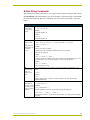
Variable Text Send_Commands
Use variable text Send_Commands to set the borders, fonts, and text.
Variable Text Send_Commands
!B
Sets a specific
button to On or
Off.
Syntax:
"’!B’,<variable text address 1-255>,<ON/OFF 0-1>"
Variables:
variable text address = 1 - 255
ON = 0
OFF = 1
Example:
SEND_COMMAND TP,"’!B’,128, 1"
Sets button 128 Off.
BTOF
Sets a specific
button's active
state to Off.
Syntax:
"’BTOF’,<variable text address>"
Variables:
variable text address = 1 - 255
Example:
SEND_COMMAND TP,"’BTOF’,255"
Sets the state for button 255 to Off.
BTON
Syntax:
Sets a specific
button's active
state to On.
Variables:
"’BTON’,<variable text address>’"
variable text address = 1 - 255
Example:
SEND_COMMAND TP,"’BTON’,128"
Sets the state for button 128 to On.
Color Passive-Matrix LCD Touch Panel
33
Programming
Variable Text Send_Commands (Cont.)
!C
Sets the border,
font, and text in
one command.
Syntax:
"’!C’,<variable text address>,<border style>,<font
size>,’<new button text>’"
Variables:
variable text address = 1 - 255
border style = See the Border Styles and Programming Numbers table on page 26.
font size = See the Font Styles and Programming Numbers table on page 26.
button text = Enter button text to appear on button.
Example:
SEND_COMMAND TP,"’!C’,1,6,6,’VCR PLAY’"
Sets the variable text button one title to VCR PLAY using a hollow medium font, and
changes the border attribute to double rounded.
!F
Shorthand version of ’FONT’
command.
Syntax:
"’!F’,<variable text address>,’<font size>’"
Variables:
variable text address = 1 - 255
font size = See the Font Styles and Programming Numbers table on page 26.
Example:
SEND_COMMAND TP,"’!F’,1,6"
Changes variable text button one font to hollow medium.
FONT
Changes the font
size (or style) of
the text in a specific button.
Syntax:
"’FONT,<variable text address>-<font size>’"
Variables:
variable text address = 1 - 255
font size = See the Font Styles and Programming Numbers table on page 26.
Example:
SEND_COMMAND TP,"’FONT,1-6’"
Changes variable text button one font to hollow medium.
!I
Syntax:
Shorthand version of 'ICON'
command.
Variables:
"’!I’,<variable text address>,’<border style>’"
variable text address = 1 - 255
border style = See the Border Styles and Programming Numbers table on page 26.
Example:
SEND_COMMAND TP,"’!I’,1,’6’"
Changes the variable text button one border style to double rounded.
ICON
Syntax:
Changes the bor"’ICON,<variable text address>-<border style>’"
der style of a spe- Variables:
cific button.
variable text address = 1 - 255
border style = See the Border Styles and Programming Numbers table on page 26.
Example:
SEND_COMMAND TP,"’ICON,25-6’"
Changes the variable text button 25 border style to double-rounded.
34
Color Passive-Matrix LCD Touch Panels
Programming
Variable Text Send_Commands (Cont.)
!T
Syntax:
Shorthand version of 'TEXT'
command.
Variables:
"’!T’,<variable text address>,’<new button text>’"
variable text address = 1 - 255
new button text = 1 - 60 characters
Example:
SEND_COMMAND TP,"’!T’,1,’VCR PLAY’"
Changes the variable text button one title to VCR PLAY.
TEXT
Use the | character to display text on multiple lines.
Enters text on a
button.
Syntax:
"’TEXT,<variable text address>-<new button text>’"
Variables:
variable text address = 1 - 255
button text = Enter button text to appear on button
Example:
SEND_COMMAND TP,"’TEXT2-VCR|PLAY’"
Sets the VCR and PLAY text on variable button 2. The | character places VCR above
PLAY on the button.
Color Passive-Matrix LCD Touch Panel
35
Programming
Shorthand Variable Text Commands
The table below lists the shorthand variable text commands you can use with the touch panel. The
shorthand command data is one-byte, non-ASCII format except for pages, passwords, text, and
bitmap names.
Shorthand Variable Text Commands
@BMF
This command allows you to program up to 12 attributes on one command line.
Syntax:
Sets multiple
attributes to a but"’@BMF’,<variable text address>,’<attribute data>’"
ton, slider, or
Variables:
gauge.
variable text address = 1 - 255
optional data = See below
Optional data:
’%R,<left>, <top>, <right>, <bottom>’ = Sets the rectangle position.
’%B’,<border styles> = See the Border Styles and Programming Numbers table on
page 26.
’%F’,<font styles> = See the Font Styles and Programming Numbers table on page 26.
’%T’,<button text > = ASCII characters (empty is clear)
’%P’,<bitmap> = Bitmap filename (empty is clear)
’%I’,<icon> = 1 - 255 (icon numbers are assigned in TPDesign3 project file)
’%J’,<text alignment> = 1 - 9 as shown the following alignment chart
1
2
3
4
5
6
7
8
9
For %C1-%C6, see the Colors and Programming Numbers table on page 26.
’%C1’,<on-state fill color>
’%C2',<off-state fill color>
’%C3’,<on-state border color>
’%C4’,<off-state border color>
’%C5’,<on-state text color>
’%C6’,<off-state text color>
Example:
SEND_COMMAND TP,"’@BMF’,255,’%T POWER |ON’
’%B’,’4’,’%C1’,’72’"
Sets the text on button 255 to POWER ON (appears on two lines), adds a triple-line border, and sets the On-state color to White.
@BMP
Adds a bitmap file
to a button.
Bitmap files are imported into TPDesign3; the numbers are assigned by the touch panel
during the download process.
Syntax:
"’@BMP’,<variable text address>,’<bitmap>’"
Variables:
variable text address = 1 - 255
bitmap = Bitmap
Example:
SEND_COMMAND TP, "’@BMP’,85,’Bitmap1’"
Adds the Bitmap1 file to button 85.
36
Color Passive-Matrix LCD Touch Panels
Programming
Shorthand Variable Text Commands (Cont.)
@BOR
Syntax:
Sets the border
style on a button.
Variables:
"’@BOR’,<variable text address>,<border style>"
variable text address = 1 - 255
border style = See the Border Styles and Programming Numbers table on page 26.
Example:
SEND_COMMAND TP, "’@BOR’,65,11"
Sets the border style to Double shadow on button 65.
@ENA
Syntax:
Enables/Disables
buttons based on
their variable text
channel.
Variables:
"’@ENA’,<variable text address>,<disable button on/off>
variable text address = 1 – 255
disable button on/off:
1 = button disabled
0 = button enabled
Example:
SEND_COMMAND TP, "’@ENA’,128,1"
Disables the button with variable text channel 128. This button will stop responding to
pushes completely, until it is sent an Enable command. Nothing short of a touch panel
Softrom firmware reload will re-enable the button. Reloading the touch panel file, reloading
the Axcess program, or resetting power on the panel or master, will not re-enable the button. It must be sent an Enable command once it has been Disabled.
@FON
Syntax:
Sets the text font
on a button.
Variables:
"’@FON’,<variable text address>,<font style>"
variable text address = 1 - 255
font style = See the Font Styles and Programming Numbers table on page 26.
Example:
SEND_COMMAND TP, "'@FON',56,32"
Sets the text on button 56 to variable font style 32.
@ICO
Assigns an icon to
a button.
Syntax:
"’@ICO’,<variable text address>,<icon>"
Variables:
variable text address = 1 - 255
icon file number = 1 - 255
Example:
SEND_COMMAND TP,"’@ICO’,16,12"
Adds icon 12 on button 16.
Color Passive-Matrix LCD Touch Panel
37
Programming
Shorthand Variable Text Commands (Cont.)
@JUS
Syntax:
Sets the text
alignment on a
button.
Variables:
"’@JUS’,<variable text address>,<text alignment>"
variable text address = 1 - 255
text alignment = 1 - 9 as shown in the following alignment chart
1
2
3
4
5
6
7
8
9
Example:
SEND_COMMAND TP, "’@JUS’,9,5"
Centers the text on button 9.
@SHO
Sets a specific
button to on or off.
Syntax:
"’@SHO’,<variable text address>,<button on/off>"
Variables:
variable text address = 1 - 255
button on/off:
0 = button Off
1 = button On
Example:
SEND_COMMAND TP,"’@SHO’,128,0"
Sets button 128 off.
@TXT
Use the | character to display text on multiple lines.
Adds text to a but- Syntax:
ton.
"’@TXT’,<variable text address>,’<text>’"
Variables:
variable text address = 1 - 255
button text = Enter button text to appear on button.
Example:
SEND_COMMAND TP,"’@TXT’,2,’VCR|PLAY’"
Sets the VCR and PLAY text on variable button 2. The | character places VCR above
PLAY on the button.
@UNI
Adds Unicode text
to a button.
Syntax:
"’@UNI’,<variable text address>,’<text>’"
Variables:
variable text address = 1 - 255
button text = Enter button text to appear on button.
Example:
SEND_COMMAND TP,"’@UNI’,2,’(Foreign Text)’"
Sets the Foreign Text on variable button 2.
Characters for Middle-Eastern languages such as Arabic are not supported within the
Unicode fonts because they are bi-directional. Buttons with Unicode fonts can only be
created and edited using TPDesign3 and NetLinx Studio. Refer to the respective
manuals for additional information.
38
Color Passive-Matrix LCD Touch Panels
Programming
Button String Commands
The table below lists string commands you can assign to buttons using the touch panel editor. Select
the PROPERTIES option in the Edit bar, press the target button, and enter the string command with
the Touch Panel keyboard. The string command is sent to the control system when you press the
button.
Button String Commands
$ID
Sets the WavePack group ID
number.
Syntax:
"’$ID <group ID>’"
Variables:
group ID = 0 (Off) - 15
Example:
$ID 15
Sets the Group ID to 15.
$SC
Sends a serial
port
send_command
within a panel, as
if sent from
Axcess.
Syntax:
"$SC <device offset>,"’<send_command>,<variable
text #>,<data>’""
Variables:
device offset = Device number
variable text # = The variable text number value on the touch panel.
data = 0 - 59 characters
Example:
$SC 1,"’@TXT’,2,’TEXT’"
The string is sends the command to put text on a button with a variable text value of 2. It is
crucial that all the correct ’ and " be used with no spaces after the commas.
Example:
$SC 1,"’SLEEP’"
Sets a touch panel to sleep.
$SL
This command does not set the panel to sleep, but actually puts a wavepack to sleep.
Activates sleep
mode on a
wireless touch
panel.
Syntax:
"$SL"
Example:
$SL
Activates sleep mode on a wireless touch panel (ViewPoint or other panel using a
SmartPack/WavePack).
$SP
Syntax:
Sends data out
"’$SP"<data>"’"
through the serial
Examples:
port of the source
panel to a destina- $SP "CALIBRATE"’"
tion panel.
Sends the Calibrate command to another panel through the Serial Port.
$SP "$SC 1,"’@TXT’,1,’TEST’""
Uses the $SP command to send a Send Command ($SC ***) to another panel through the
Serial Port.
Color Passive-Matrix LCD Touch Panel
39
Programming
Button String Commands (Cont.)
$ST
When the touch panel’s input time matches the sleep time, the panel goes to sleep.
Sets the idle time
to activate sleep
mode for a touch
panel in 1-minute
increments.
Syntax:
"’$ST <sleep timeout>’"
Variables:
sleep timeout = 1 (Off) - 120 (minutes)
Example:
$ST 5
Sets the touch panel’s sleep time to 5 minutes.
$TO
Syntax:
Sends touch coor"’$TO <touch output enabling via the program port>’"
dinates out
Variables:
through the protouch output enabling = 0 (Input Touch Only), 1 (Input and Output Touch)
gram port.
Example:
$TO 0
Sets the panel only to input touch.
40
Color Passive-Matrix LCD Touch Panels
Upgrading the Firmware
Upgrading the Firmware
In order to upgrade the firmware in the panel, you can either return the panel to AMX or replace the
necessary EPROM chips yourself. Standard memory on the G3 boards for the CP series of touch
panels is 1 MB of base memory. The EPROM chips are pre-loaded with the firmware, and can be
obtained from the factory or dealer, then installed into the touch panel circuit board.
AXT-CP EPROM Replacement
Remove the EPROMs from the AXT-CP:
1. Discharge the static electricity from your body by touching a grounded object.
2. Remove the 2-pin power connector from the rear side of the panel. If you are using power via
AXlink, remove the AXlink connector.
3. Flip the touch panel face down onto a soft cloth, and remove the seven Phillips-head screws
from the bottom panel. Then, gently remove the panel.
4. Remove the Phillips-head screw located in the center of the circuit card.
5. Gently tilt the circuit card down towards the connector side and pull backwards until you clear
the connector housing. Then, slowly rotate the circuit card backwards until you can lay it down
flat with the EPROMs exposed as seen in FIG. 16. EPROMS have stickers indicating the
firmware version.
Notches
EVEN
1
ODD
4
32-pin sockets
EPROM Odd
and Even
FIG. 16 EPROM location on a TiltScreen touch panel
6. Carefully remove each EPROM individually by inserting a Phillips screwdriver with a nonconducting flat-blade between the EPROM and the connection site (at the notch side).
7. Gently pry the EPROMs from their connection base until they begin to loosen. Carefully pull
them out by either using an EPROM removal device or by gently pulling them from the base
(making sure to evenly pull the prongs from the socket holes)
.
Insert the EPROMs with the notches facing the correct direction. Match the Even and
Odd EPROM placement with the location shown above.
During the replacement process, cables may be pulled from their connections and
should be re-checked to confirm they are securely connected.
Color Passive-Matrix LCD Touch Panels
41
Upgrading the Firmware
8. Using the new EPROMs, match up the socket holes to their respective prong and the notches to
the correct direction for both the new Odd and Even chips.
9. Insert all the prongs simultaneously until each is firmly resting in its socket hole and the entire
chip is securely connected to its base.
10. Rotate the circuit card back to the original position and place it in the touch panel housing.
11. Plug the 2-pin power or AXlink connector back into the touch panel for approximately
1 minute. Once you can confirm the panel is receiving power, remove the connector, align the
screw hole and insert the Phillips-head screw and tighten.
12. Replace the bottom panel and align the screw holes. Insert the seven Phillips-head screws and
tighten.
13. Plug all connectors back into the touch panel.
AXM-CP (/PB) and AXD-CP (/PB) EPROM Replacement
If the unit is already mounted to a surface, remove it at this time. Refer to the Installation section on
page 3 for more information.
1. Discharge the static electricity from your body by touching a grounded object.
2. Remove the 2-pin power connector from the rear side of the panel. If you are using power via
AXlink, remove the AXlink connector.
3. Flip the touch panel face down onto a soft cloth, and remove the seven Phillips-head screws
from the bottom panel. Then, gently remove the housing.
4. Remove the Phillips-head screw located in the center of the circuit card.
5. Gently tilt the circuit card down towards the connector side and pull backwards until you clear
the connector housing. Then, slowly rotate the circuit card backwards until you can lay it down
flat with the EPROMs exposed as seen in FIG. 17. EPROMS have stickers that indicating the
firmware version.
JP2JP1JP3
1
1
1
EVEN
ODD
32-pin sockets
EPROM Odd
and Even
FIG. 17 EPROM location on a mounted touch panel
6. Carefully remove each EPROM by inserting a Phillips screwdriver with a non-conducting flatblade between the EPROM and the connection site (at the notch side).
42
Color Passive-Matrix LCD Touch Panels
Upgrading the Firmware
7. Gently pry the EPROMs from their connection base until they begin to loosen. Carefully pull
them out by either using an EPROM removal device or by gently pulling them from their base
(making sure to evenly pull the prongs from their socket holes).
.
Insert the EPROMs with the notches facing the correct direction. Match the Even and
Odd EPROM placement with the location shown above.
During the replacement process, cables may be pulled from their connections and
should be re-checked to confirm they are securely connected.
8. Using the new EPROMs, match up the socket holes to their respective prong and the notches to
the correct direction for both the new Odd and Even chips.
9. Insert all of the prongs simultaneously until each is firmly resting in its socket hole and the
entire chip is securely connected to its base.
10. Rotate the circuit card back to the original position and place it in the touch panel housing.
11. Plug the 2-pin power or AXlink connector back into the touch panel for approximately
1 minute. Once you can confirm the panel is receiving power, remove the connector, align the
screw hole and insert the Phillips-head screw and tighten.
12. Replace the housing on the touch panel and align the screw holes. Insert the seven Phillipshead screws and tighten.
13. Plug all connectors back into the touch panel.
14. Re-install the unit to its appropriate mounting surface.
Color Passive-Matrix LCD Touch Panels
43
Upgrading the Firmware
44
Color Passive-Matrix LCD Touch Panels
Replacing the Batteries
Replacing the Batteries
There are two lithium batteries on the touch panel card, with a life of approximately 5 years. They
protect stored commands and pages against a power outage. The batteries are not used when DC
power is supplied to the touch panel. You should write down the replacement date on a label by
adding 5 years to the date of installation, and attach it to the panel for future reference.
FIG. 18 Lithium battery and socket
Static electricity can damage electronic circuitry. Before removing the touch panel
circuit card from the enclosure, discharge any accumulated static electricity from your
body and flat-blade tool by touching a grounded metal object.
Before replacing the lithium batteries, make sure you have a current copy of the pages stored in the
touch panel. This will avoid any inadvertent loss of data or a service outage. To replace the lithium
batteries, you will need a Phillips screwdriver and a non-conducting flat-blade tool to slip under
each battery to pry it up and out of the socket.
AXT-CP Batteries
Remove the lithium batteries from the AXT-CP:
1. Discharge the static electricity from your body by touching a grounded object.
2. Remove the two-pin power connector from the rear side of the touch panel. If you are using
power via AXlink, remove the AXlink connector.
3. Flip the touch panel face down onto a soft cloth, and remove the seven Phillips-head screws
from the bottom panel. Then, gently remove the panel.
4. Remove the Phillips-head screw located in the center of the circuit card.
5. Gently tilt the circuit card down towards the connector side and pull backwards until you clear
the connector housing. Then, slowly rotate the circuit card backwards until you can lay it down
flat with the batteries exposed.
6. Carefully slide one battery out of its socket, and insert the new battery
.
There is a danger of explosion if you replace the battery incorrectly. Replace the
battery with the same or equivalent type recommended by the manufacturer. Dispose
of the used battery according to the manufacturer’s instructions. Never recharge,
disassemble, or heat the battery above 212 °F (100 °C). Never solder directly to the
battery or expose the contents of the battery to water.
7. Rotate the circuit card back to the original position and place it in the touch panel housing. Do
not insert the mounting screw.
Color Passive-Matrix LCD Touch Panels
45
Replacing the Batteries
8. Plug the 2-pin power or AXlink connector back into the touch panel for approximately 1
minute. Then, remove connector from the panel again.
9. Gently tilt the circuit card down towards the connector side and pull backwards until you clear
the connector housing. Then, slowly rotate the circuit card backward again until you can lay it
down flat with the batteries exposed.
10. Carefully slide the other battery out of its socket, and insert the new battery.
11. Rotate the circuit card back to the original position and place it in the touch panel housing.
Align the screw hole and insert the Phillips-head screw and tighten.
12. Place the bottom panel on the touch panel and align the screw holes. Insert the seven Phillipshead screws and tighten.
13. Plug all connectors back into the touch panel.
AXD-CP (/PB), and AXM-CP/PB Batteries
Remove the lithium batteries from the touch panel:
1. Discharge the static electricity from your body by touching a grounded object and unscrew the
Decor-style faceplate.
2. Using a flat-blade tool unscrew the Decor-style faceplate.
3. Remove the four #6-32 mounting screws and carefully lean the touch panel backward to
expose the connectors.
4. Disconnect all the connectors and remove the touch panel from the Back Box or equipment
rack.
5. Flip the touch panel facedown onto a soft cloth and remove the four circuit card spacers.
6. Carefully pry one battery out of its socket and insert the new battery.
7. Return the touch panel to the Back Box or equipment rack and connect the power or AXlink
connector back into the rear side of the panel for approximately 1 minute. Then, remove the
connector from the panel again.
8. Flip the touch panel facedown onto a soft cloth and carefully remove the other battery out of its
socket and insert the new battery.
9. Return the touch panel to the Back Box or equipment rack and reconnect all the connectors.
10. Insert the four rack mounting screws and tighten.
11. Place the Decor-style faceplate onto the bezel and install the engraved overlay.
46
Color Passive-Matrix LCD Touch Panels
Replacing the Batteries
Color Passive-Matrix LCD Touch Panels
47
brussels • dallas • los angeles • mexico city • philadelphia • shanghai • singapore • tampa • toronto* • york
3000 research drive, richardson, TX 75082 USA • 469.624.8000 • 800.222.0193 • fax 469.624.7153 • technical support 800.932.6993
036-004-1794 7/03 ©2003 AMX Corporation. All rights reserved. AMX, the AMX logo, the building icon, the home icon, and the light bulb icon are all trademarks of AMX Corporation.
AMX reserves the right to alter specifications without notice at any time. *In Canada doing business as Panja Inc.
AMX reserves the right to alter specifications without notice at any time.