1
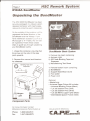
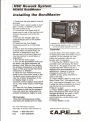
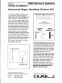
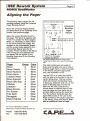
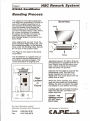
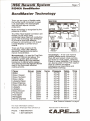
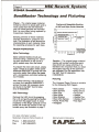
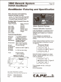
BondMaster
R1346A
BondMaster HSC Rework System
BondMaster Manual
1.
2.
3.
4.
5.
6.
7.
8.
Unpacking the BandMaster
Installation
Universal Paging Bonding Fixture
Aligning the Pager
Bonding Process
BandMaster Technology
BandMaster Technology and Fixturing
BandMaster Fixturing and Specification
Manufactured exclusively for
For service questions call:
Automation Production Equipment
Phone: 305-451-4722
Fax: 305-451-3374
@ MOTOROLA
CAIIREII~
48 Coral Way, MM105.2
Key Largo, FL 33037, USA
---
-- ----
-
-
--
-
--
HSC Rework System
Page 2
R1346A BondMaster
Unpacking the BandMaster
The HSC 9000 BondMaster has been
securely packaged in a robust custom
designed container with inserts separating and protecting each component.
On the outside of the container will be
registered the Model Number of the
BandMaster and the Voltage. If you
have ordered an accessory such as a
Microscope or X-Y Table, this will also
be registered. Follow these simple
steps to guide you through unpacking
your BondMaster safely:
1. Unseal the container, ensuring that
the arrows on the side of the case
point upwards.
BandMaster Basic System
3. Remove top insert containing:
a) Halogen Light
b) ESD safe Bonding Tape and
Dispenser
c) Manufacturing Test Sheet
2. Remove this manual and literature
for reference.
Bonding Tape and
Dispenser
4. Remove bottom insert containing:
a) BondMaster
b) Support Base Block (Gold)
c) Foot switch
d) Power cord
Fixturing
& Pins
em
~~:: :
m
'.:.:.:.:
C.::=::?...:
.;.;.:.:.:
.......
:.:..: ~.:.:..:
:::)!
Optional:
· MasterLens
· Universal Pager Fixture Kit includes:
· Universal Bonding Fixture (Black)
· 1 pk set location Pins (Gold)
· 1 pk set location Pins (Silver)
· 1 pk set Memo support pins (Black)
· Intermediate Spacer Fixture (Gold)
I
Component Parts
For more information contact
Motorola s America s Parts Division at:
Phone:
Fax:
1-800-543-9191
1-847-538-8079
Manufactured for Motorola by:
CA.RE.~
HSC Rework System
Page 3
R1J46A BondMaster
Installing the BondMaster
1. Check that the work bench is sturdy
and level.
2. Ensure that a power supply is available (11OVACor 220VAC),and that
the main power is off.
3. Connect the Foot Pedal and AC
power cord to rear of the machine and
connect the power cord to the AC
supply.
4. Connect the halogen light and
optional MasterLens to the sockets
provided.
5. Check that the Foot Pedal/
Continuous switch is in Foot Pedal
mode.
6. Ensure that the Heating Element is
in place within the Bond Head, the
element is designed to carry the
thermal load of the Bond Head and
must be inserted to avoid failure or
degradation.
7. Turn ON the main supply.
8. Turn ON the BondMaster main supply switch, the digital controller will
conduct a Self Test and then display
the ambient temperature of the Bond
Head in RED and the Set Point bond
temperature in GREEN.
9. Place the Foot Pedal/Continuous
switch to the Continuous mode to test
the Bond Head heating element and
note the ambient temperature in the
red display begin to ramp.
Continue until the display reads 250°F
121°C, then switch back to Foot Ped~1
mode.
.
10. Press the Foot Pedal momentarily
then release to test that the temperature cycle starts by noting when the
ambient temperature begins to ramp.
PID Controller
Three thermaVtemperature profiles
have been pre-loaded and are ready
Important: Do not switch off the BandMaster
until the display registers under 110°F (43°C)
as this will rapidly degrade heater life.
Controller
to go for Bravo and other pagers, with
an additional profile allocated for future
products. Do not change any field
within the controller until you are
familiar with it's operation.
11. Pressing the "INDEX" key on the
controller once will display the Bond
Time as "t1", the pager bond time 1:45
minutes has been factory set as a
default and is recommended for most
applications, however it may be
changed by using the "UP" and
"DOWN" arrows, press "ENTER" to
save a new time.
12. Press "INDEX" again to step to the
Bond Profile "Prof", the default profile
is #1, and may be changed from 1 thru
4 using the same procedure as changing time but we recommend that
Profile #1 is used.
13. Press "INDEX" again to display the
Bond TemperatureISPI which can be
changed as above, the prefix in ISPI
indicates the profile number, we
recommend you use the factory set
temperature.
14. Press "INDEX" to exit.
For more information contact
Motorola's America's Parts Division at:
Manufactured for Motorola by:
Phone:
Fax:
CA.RE.p..t~
1-800-543-9191
1-847-538-8079
HSC Rework System
Page 4
R1346A BondMaster
Universal
Pager Bonding Fixture Kit
The Basic BondMaster system does
not include the optional Universal
Pager Fixture Kit.The BondMaster will
accommodate all Motorola pager fixtures, or the user may decide to fabricate a special assembly. The optional
two piece Universal Pager Fixture Kit
is supplied banded and assembled for
Bravo type pagers (the band must be
removed before use). The Base Block
(gold) supplied with the BondMaster
supports the kit, which includes an
Intermediate Spacer (gold) and the top
Universal Pager Fixture (black), orientated for Bravo pagers. Also included
are two sets of location pins, silver and
gold, which are color coded for use
with different pager types. The Memo
Support Pins are black.
AssemblyDock
,
0
0
00
Bonding Dock
>
Universal Pager Fixture Kit
Kit
[
I
:
l-U--:~dd
)
~;
~
I
BIOOkT--J
supplied with BandMaster
L_h
i
U
Location
Pins
\..,
!
Memo
Support Pin
Silver
Black
With the BondMaster facing the user,
note the Assembly Dock location holes
on the left of the base plate, these will
locate with the roll pins on the bottom
of the gold Base Block. The Universal
Pager Fixture Kit will retain the pager
and display assembly once the
HSC/LCD has been aligned using the
correct location pins and the anti-static
thermal bonding insulating tape supplied. See next page. Once the pager
and display are securely taped, the
Base Block can be moved to the
Bonding Dock location under the
Bonding Head. Note:the Intermediate
Spacer is not required when using
Motorolastandard tooling.
For more information contact
Motorola s America s Parts Division at:
Manufactured for Motorola by:
Phone: 1-800-543-9191
Fax:
1-847-538-8079
CA.RE.~
HSC Rework System
Page 5
R1346A BondMaster
Align-ing the Pager
The following steps prepare for the
bonding process, using the Universal
Pager Bonding Fixture:
Mount the Universal Paging Fixture
and Base Block at the Assembly Dock
location (see previous page).
Select the correct Bonding Anvil for
the pager.The fixture is supplied with
"Anvil A" in position for Bravo pagers.
When it is necessary to select "Anvil
B" the fixture should be rotated 180
degrees on the Intermediate Spacer
and the correct holes aligned to the
Intermediate Spacer pins by the
Location Arrows marked on the fixture.
If the wrong pins are selected then
the display will not register to the
Bonding Head when in the Bonding
Dock location.
"Anvil A" Common Bravo Types
"Anvil A"
o
o@
o
A1
0 0
CB
o
A1
0 0
CB
00
o A2
Universal
Bonding
Pager
Fixture
OA2
o..
o..
0Mounting'HolesFor"AnvilB"
0MountinglHolesFor"AnvilA"
00
o
o ~
.
"Anvil
0
B"
diE
"Anvil B" For Renegade,
Freespirit and Encore
The above illustration shows the positions of the
Tooling Pins and which Anvil to use with which pager
type.
Pager
Bravo
Bravo Classic
Bravo Numeric
Bravo Alpha
Lifestyle (New)
BravoExpress
BravoUltra Exp
Lifestyle
Lifestyle+
BravoEncore
Pro Encore
Free Spirit
Renegade
Memo Express
Group
Color
C
C
C
C
C
A
A
B
B
D
D
E
E
A
Silver
Silver
Silver
Silver
Silver
Gold
Gold
Silver
Silver
Gold
Gold
Silver
Silver
Gold
The silver tooling pins are used for
Bravo and the gold pins are for Bravo
Express pager types. Locate the pager
in the fixture using the appropriate
pins, see illustration at left.
Lay the LCD on a clean flat surface
with the side to be bonded to the connector facing down. The top surface,
which will contact the Bonding Head,
is facing up. Dispense and cut a 3 inch
piece of Bonding Tape and lay the
tape over the HSC material end,
ensure there is sufficient tape to capture the pager and that there are no
wrinkles before pealing the assembly
from the surface. Carefully align the
taped HSC traces of the LCD to the
finger contacts of the pager supported
in the fixture. Press and secure,
then
add an additional layer of tape.
For more information contact
Motorola's America's Parts Division at:
Phone:
Fax:
1-800-543-9191
1-847-538-8079
Manufactured for Motorola by:
CA.RE.It~.~
HSC Rework System
Page 6
R1346A BondMaster
Bonding
Process
The objective of the tape preparation
and alignment procedure ISnot only to
secure the aligned assembly, but to
also prevent tne Bonding Head sticking to the flexible circuit curing the
bond process and to insulate the circuit from the Bond Head. It also allows
for a linear distribution of pressure
throughout the flexible circuit as the
conductive epoxy reaches reflow
and changes shape to conform to the
Bond Head.
Once aligned and secured, move the
entire Universal Pager Fixture Kit, with
the installed assembly,to the Bonding
Dock under the Bonding Head. Secure
the roll pins in the location holes.
Head
,
,
Bond Blade
/-.-...
Depress the foot pedal to activate the
temperature cycle. The Set Point
(green display) will convert to the
digital timer and count down from the
preset time to zero.
~
When the Timer reaches zero, disengage the foot pedal and immediately
release the lever and allow the pager
and display to cool before removing.
Carefully peel the anti-static bonding
tape from the HSC connector and
pager assembly.
o
@o
Caution - Hot
radiating surface.
DO NOT touch
BondHead.
For more information contact
Motorola s America s Parts Division at:
Fax:
t
adjusting pressure for Memo Express
(monosotropic) is supplied with the fixture. Slowl¥ move the Bonding Lever
down until It contacts the anti-static
tape and locks into position.
Pager
Located
in
Phone:
\
Fixture
The BondMaster is supplied with correct pressure tension adjustment for
anosotropic and planer paQers.The
correct procedure for alignmg and
.
)
HSC
The Pager is now ready for the bonding process.
Fixture
Bond Head
1-800-543-9191
1-847-538-8079
J
-~~
~
Manufactured for Motorola by:
CA.RE.~
HSC Rework System
Page 7
R1346A BondMaster
8~ndMaster Technology
There are two types of flexible cable
that will be found connected to pager
LCD assemblies. The technologies
vary but both require a similar
preparation.
BEFORE
Mylar technology is recognized by the
presence of solder.
AFTER
The HSC (Heat Sealed Connector) are
flexible circuits which have
conductive traces filled with conductive
epoxy.The technology was developed
to provide a quick and effective
process for connecting a LCD (Liquid
Crystal Display) to printed circuit
boards.
~
~ ~f ~,
Tpager Insulator Conductive
Fingers
Conductive Pager
Epoxy
Fingers
Bond
Epoxy
Insulator
CLEANING
There are three variants of this
technology, which offer different
electricaf, mechanical and performance characteristics.
Monosotropic - Is used for Fine Pitch
projects of O.22mmand above. The
materials contain gold and nickel
particles offering very low electrical
resistance. Its typical yellow appearance derives from the titanium dioxide
used in the thermoset adhesive
coating process.
Group
Pager
C
Bravo
Bravo Classic
C
C
Bravo Numeric
C
Bravo Alpha
C
Lifestyle (New)
A
Bravo Express
A
Bravo Ultra Exp
B
Lifestyle
B
Lifestyle +
D
Bravo Encore
D
Pro Encore
E
Free Spirit
E
Renegade
A
Memo Express
Color
Silver
Silver
Silver
Silver
Silver
Gold
Gold'
Silver
Silver
Gold
Gold
Silver
Silver
Gold
Anosotropic - A low cost material
yielding reliable bond connections,
filled with gold plated nickel particles
and found on most pagers, replacing
Planar in many instances. The material
can also be used in Fine Pitch applications of O.29mmand above.
Indications are Green/White and
Black/White markings.
Turns
10
10
10
10
10
10
10
10
10
10
10
10
10
11
Pressure
75 PSI
75 PSI
75 PSI
75 PSI
75 PSI
75 PSI
75 PSI
75 PSI
75 PSI
75 PSI
75 PSI
75 PSI
75 PSI
83 PSI
Temp.
302°F
302°F
302°F
302°F
302°F
302°F
302°F
302°F
302°F
302°F
302°F
302°F
302°F
330°F
Time
1:45
1:45
1:45
1:45
1:45
1:45
1:45
1:45
1:45
1:45
1:45
1:45
1:45
1:45
Note "Pressure Calibration" on page 9.
For more information contact
Motorola's America's Parts Division at:
Manufactured for Motorola by:
Phone:
Fax:
CA.REII~"I'II:fA
1-800-543-9191
1-847-538-8079
Page 8
HSC Rework System
R1J46A BondMaster
BondAfaster Technology and Fixturing
Planar - The original pager material,
Precise and Repeatable Bonding
of HSCand MylarSolder Materials
limited to O.3mmor above pitch and is
more costly than the new technologies. No metal particles are included
and it is more often being replaced by
Anosotropic materials.
120
110
100 ~ MaxImum BoncIngTempendin
90
80
JI
I! 70
Bonding all three of these materials
requires temperature, pressure and
time. The illustration at left shows the
characteristics of each material. Note
the operating envelope for each type.
i
PAGER PREPARATION
o
-10
MylarTechnology
Mylar solderedflexible circuits are
removedusing a soldering iron, reflowing each connectionas the circuit is
gently peeled away from the board.
To prepare the new LCD circuit, simply
apply a bead of no-clean solder paste
reference 6680333E72 across the new
connector pads, then reflow the paste
with a temperature controlled soldering
iron R1343A.
:
I
1L<40
30
20
10
IIonolOtroplc
18O"C I
l
16O"C
Anisotropic 150°C
HSC Force/Pound8
J
Planar 140°-150"C
Envelope
'83137 SolderIng
Hot B... Envel
~
1~1~
1~ 1~1~1n
Temperature
Caution
- The original
1~
~
"C
pager material
residue will contain conductive particles which can cause shorting. It is
therefore very important that you clean
thoroughly ensuring all the particles
are removed. For this application use
the SMT Tool Kit reference
0180303E45.
Flxturlng
After reflow (tinning), add a bead of
no-clean flux reference 6680333E71
across the pads. All necessary tools
are found in the SMT Tool Kit reference 0180303E45.
HSC Technology
Remove the HSC circuit by grasping
the LCD and gently peeling the flexible
circuit from the pager board. A close
inspection of the finger contacts on the
board will reveal the residue of the old
bondedepoxy,seeillustrationon page7.
For more information contact
Motorola's America's Parts Division at:
Phone:
Fax:
1-800-543-9191
1-847-538-8079
The Universal Pager Fixture is suitable
for the following HSC Pagers:
· Bravo LX-FLX
· Bravo Encore
·
·
·
·
·
·
Bravo Classic
Bravo Numeric
Bravo Plus
Bravo Alpha
Bravo Express
Brave;>Ultra Express
· Lifestyle (New)
·
Pronto, Pronto Flex
· FreeSpirit
· Pro Encore
· Lifestyle
·
Lifestyle Plus
· Renegade
Manufactured for Motorola by:
HSC Rework System
Page 9
R1346A BondMaster.
B~ndAfaster
Fixturing and Specification
Memo Express LCD Positioning
upgrade package includes:
- Linearx-v MicrometerBearingTable
- Microscopewith mountinghardware
- Universal Pager Bonding Fixture
Portable Radio Products Fixture for
the following:
Radio Products
Pager Products
Hot Bar
.Advisor
.Scriptor
.Advisor Gold
.Advisor Plus
.Tango
.MTX 838
.MTX 8000
.MTX 9000
.HT 1000
.HT 2000
.MTS 2000
Technical Specification
Electrical:
Current:
Power:
Mechanical
110V/220V 50/60Hz
5 Amps continuous
200 Watts continuous
Rugged Anodized
Aluminum Plate
Dimensions: 15 in. x 12 in. x 12 in.
(381 x 305 x 305mm)
Weight:
14 Ibs (6.36 Kg)
Temperature
Ambient to 550°F (288°C)
Envelope:
Pressure
Envelope:
0-100 Ibs (45.45 Kg)
Time:
Programmable
1 sec-3 minutes
~ 140
! 120
~loo
~
80
60
40
20
1/ ,/
,~
."",,
,../183°C Eutectic /
/2
I/
.I
Ji
/1
.-;
..():.~~:>..
60
I13
Pressure Calibration Pr~cedure:
Each BondMaster is calibrated before
leaving the factory and the Pressure
Wheel is set in place by a "Pressure
Set Pin."
.
If.it is necessary to calibrate the
system, simply reset the location as
follows:
Raise Pressure Wheel and Bond Head
by turning wheel in direction of arrow
in Figure A.
Pressure Wheel
FigureA
Once the wheel is topped out, rotate
wheel in reverse direction ten (10) full
turns, as Figure B.
Reflow Profiles
220
200
180
~ 160
Memo Express Package
ISeI
Point
Temperature/
,/
/
Figure 8
I
4
1-4DFFColon
120
Seconds
180
240
For more information contact
Motorola's America's Parts Division at:
Phone:
1-800-543-9191
Fax:
1-847-538-8079
This will apply 75 Ibs. (7.5 Ibs per
rotation).
End of procedure.
Manufactured for Motorola by: