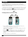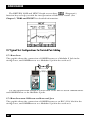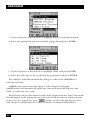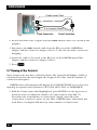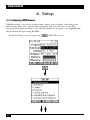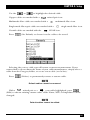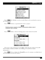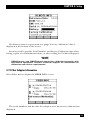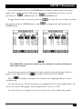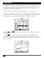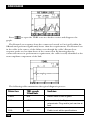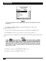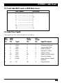
1
AUGUST 2000
TS1000A-R5
TS1002A
TS1003A
OMNIScanner
TX
RX
Fiber
O M N I
850 nm
1300/1310
TX
RX
nm
Fiber
O M N I
850 nm
1300/1310
nm
ote
I Rem
O M N
PASS
r
nne
I Sca
O M N
US
STAT
FAIL
ARD
UIT GU
CIRC
GE
CHAR
%
1
ghi
4
prs
7
A/a
CUSTOMER
SUPPORT
INFORMATION
abc
2
jkl
5
tuv
8
def
3
mno
6
wxy
9
qz
0
?
Order toll-free in the U.S. 24 hours, 7 A.M. Monday to midnight Friday: 877-877-BBOX
FREE technical support, 24 hours a day, 7 days a week: Call 724-746-5500 or fax 724-746-0746
Mail order: Black Box Corporation, 1000 Park Drive, Lawrence, PA 15055-1018
Web site: www.blackbox.com • E-mail: [email protected]
FCC INFORMATION
FEDERAL COMMUNICATIONS COMMISSION
AND
CANADIAN DEPARTMENT OF COMMUNICATIONS
RADIO FREQUENCY INTERFERENCE STATEMENTS
This equipment generates, uses, and can radiate radio frequency energy and if not
installed and used properly, that is, in strict accordance with the manufacturer’s
instructions, may cause interference to radio communication. It has been tested
and found to comply with the limits for a Class A computing device in accordance
with the specifications in Subpart J of Part 15 of FCC rules, which are designed to
provide reasonable protection against such interference when the equipment is
operated in a commercial environment. Operation of this equipment in a
residential area is likely to cause interference, in which case the user at his own
expense will be required to take whatever measures may be necessary to correct the
interference.
Changes or modifications not expressly approved by the party responsible for
compliance could void the user’s authority to operate the equipment.
This digital apparatus does not exceed the Class A limits for radio noise emission from digital
apparatus set out in the Radio Interference Regulation of the Canadian Department of
Communications.
Le présent appareil numérique n’émet pas de bruits radioélectriques dépassant les limites
applicables aux appareils numériques de la classe A prescrites dans le Règlement sur le
brouillage radioélectrique publié par le ministère des Communications du Canada.
1
OMNISCANNER
NORMAS OFICIALES MEXICANAS (NOM)
ELECTRICAL SAFETY STATEMENT
INSTRUCCIONES DE SEGURIDAD
1. Todas las instrucciones de seguridad y operación deberán ser leídas antes de
que el aparato eléctrico sea operado.
2. Las instrucciones de seguridad y operación deberán ser guardadas para
referencia futura.
3. Todas las advertencias en el aparato eléctrico y en sus instrucciones de
operación deben ser respetadas.
4. Todas las instrucciones de operación y uso deben ser seguidas.
5. El aparato eléctrico no deberá ser usado cerca del agua—por ejemplo, cerca
de la tina de baño, lavabo, sótano mojado o cerca de una alberca, etc..
6. El aparato eléctrico debe ser usado únicamente con carritos o pedestales que
sean recomendados por el fabricante.
7. El aparato eléctrico debe ser montado a la pared o al techo sólo como sea
recomendado por el fabricante.
8. Servicio—El usuario no debe intentar dar servicio al equipo eléctrico más allá
a lo descrito en las instrucciones de operación. Todo otro servicio deberá ser
referido a personal de servicio calificado.
9. El aparato eléctrico debe ser situado de tal manera que su posición no
interfiera su uso. La colocación del aparato eléctrico sobre una cama, sofá,
alfombra o superficie similar puede bloquea la ventilación, no se debe colocar
en libreros o gabinetes que impidan el flujo de aire por los orificios de
ventilación.
10. El equipo eléctrico deber ser situado fuera del alcance de fuentes de calor
como radiadores, registros de calor, estufas u otros aparatos (incluyendo
amplificadores) que producen calor.
11. El aparato eléctrico deberá ser connectado a una fuente de poder sólo del
tipo descrito en el instructivo de operación, o como se indique en el aparato.
2
NOM STATEMENT
12. Precaución debe ser tomada de tal manera que la tierra fisica y la polarización
del equipo no sea eliminada.
13. Los cables de la fuente de poder deben ser guiados de tal manera que no
sean pisados ni pellizcados por objetos colocados sobre o contra ellos,
poniendo particular atención a los contactos y receptáculos donde salen del
aparato.
14. El equipo eléctrico debe ser limpiado únicamente de acuerdo a las
recomendaciones del fabricante.
15. En caso de existir, una antena externa deberá ser localizada lejos de las lineas
de energia.
16. El cable de corriente deberá ser desconectado del cuando el equipo no sea
usado por un largo periodo de tiempo.
17. Cuidado debe ser tomado de tal manera que objectos liquidos no sean
derramados sobre la cubierta u orificios de ventilación.
18. Servicio por personal calificado deberá ser provisto cuando:
A: El cable de poder o el contacto ha sido dañado; u
B: Objectos han caído o líquido ha sido derramado dentro del aparato; o
C: El aparato ha sido expuesto a la lluvia; o
D: El aparato parece no operar normalmente o muestra un cambio en su
desempeño; o
E: El aparato ha sido tirado o su cubierta ha sido dañada.
3
OMNISCANNER
TRADEMARKS
The trademarks mentioned in this manual are the sole property of their owners.
4
CONTENTS
CONTENTS
1. Introduction . . . . . . . . . . . . . . . . . . . . . . . . . . . . . . . . . . . . . . . . . . . . . . 9
1.1 The Digital Solution for Fiber and Copper . . . . . . . . . . . . . . . . . . 9
1.2 The Graphical User Interface . . . . . . . . . . . . . . . . . . . . . . . . . . . . . 9
1.3 OMNIRemote . . . . . . . . . . . . . . . . . . . . . . . . . . . . . . . . . . . . . . . . . . 9
1.4 OMNIFiber . . . . . . . . . . . . . . . . . . . . . . . . . . . . . . . . . . . . . . . . . . . . 9
1.5 ScanLink Tools Software . . . . . . . . . . . . . . . . . . . . . . . . . . . . . . . . . 10
1.6 OMNIScanner’s Display . . . . . . . . . . . . . . . . . . . . . . . . . . . . . . . . . . 10
1.7 OMNIScanner’s Keypad . . . . . . . . . . . . . . . . . . . . . . . . . . . . . . . . . . 11
1.8 OMNIRemote’s LED Indicators . . . . . . . . . . . . . . . . . . . . . . . . . . . 14
1.9 OMNIRemote Keys . . . . . . . . . . . . . . . . . . . . . . . . . . . . . . . . . . . . . . 14
1.10 When to Use OMNIRemote. . . . . . . . . . . . . . . . . . . . . . . . . . . . . . 15
1.11 Connecting OMNIScanner and OMNIRemote . . . . . . . . . . . . . . 15
1.12 OMNIFiber’s LED Indicators. . . . . . . . . . . . . . . . . . . . . . . . . . . . . 17
1.13 Attaching the OMNIScanner Fiber Adapters . . . . . . . . . . . . . . . . 17
1.14 Editing with OMNIScanner . . . . . . . . . . . . . . . . . . . . . . . . . . . . . . 18
1.14.1 Predefined Lists . . . . . . . . . . . . . . . . . . . . . . . . . . . . . . . . . . . 19
1.14.2 Editing Numeric Fields with the Spin Control . . . . . . . . . . 19
1.14.3 Editing Alphanumeric Fields . . . . . . . . . . . . . . . . . . . . . . . . 20
1.15 Technical Support . . . . . . . . . . . . . . . . . . . . . . . . . . . . . . . . . . . . . 21
1.16 Product Versions. . . . . . . . . . . . . . . . . . . . . . . . . . . . . . . . . . . . . . . 21
2. Getting Started: Twisted Pair Networks . . . . . . . . . . . . . . . . . . . . . . . . 23
2.1 Charging OMNIScanner’s Battery. . . . . . . . . . . . . . . . . . . . . . . . . . 23
2.2 OMNIScanner’s Project Screen. . . . . . . . . . . . . . . . . . . . . . . . . . . . 23
2.3 Certification of Network Installations . . . . . . . . . . . . . . . . . . . . . . . 24
2.4 Setting the Reference . . . . . . . . . . . . . . . . . . . . . . . . . . . . . . . . . . . . 25
2.5 Project Selection . . . . . . . . . . . . . . . . . . . . . . . . . . . . . . . . . . . . . . . . 26
2.6 Running an Autotest for Twisted Pair Cabling. . . . . . . . . . . . . . . . 28
2.6.1 Saving Twisted Pair Autotest Results . . . . . . . . . . . . . . . . . . . 29
2.6.2 Viewing Twisted Pair Autotest Results . . . . . . . . . . . . . . . . . . 32
2.7 Typical Test Configurations for Twisted Pair Cabling . . . . . . . . . . 36
2.7.1 Basic Link. . . . . . . . . . . . . . . . . . . . . . . . . . . . . . . . . . . . . . . . . 36
2.7.2 Basic Link with 110 Block and Modular 8 Jacks . . . . . . . . . . 36
2.7.3 Full Channel with Modular 8 Jacks . . . . . . . . . . . . . . . . . . . . 37
2.7.4 Permanent Link. . . . . . . . . . . . . . . . . . . . . . . . . . . . . . . . . . . . 38
3. Getting Started: Fiber Optic Networks . . . . . . . . . . . . . . . . . . . . . . . . . 39
3.1 Charging OMNIScanner’s Battery. . . . . . . . . . . . . . . . . . . . . . . . . . 39
3.2 OMNIScanner’s Project Screen. . . . . . . . . . . . . . . . . . . . . . . . . . . . 39
3.3 Certification of Fiber Installations. . . . . . . . . . . . . . . . . . . . . . . . . . 40
3.4 Setting the Reference for Fiber Optic Cabling. . . . . . . . . . . . . . . . 41
5
OIMNISCANNER
3.5 Project Selection . . . . . . . . . . . . . . . . . . . . . . . . . . . . . . . . . . . . . . . . 43
3.6 Running an Autotest for Fiber Optic Cabling . . . . . . . . . . . . . . . . 45
3.6.1 Preparing an Autotest . . . . . . . . . . . . . . . . . . . . . . . . . . . . . . . 45
3.6.2 Loopback Autotest Using OMNIFiber Main . . . . . . . . . . . . . 47
3.7 Running a Fiber Autotest . . . . . . . . . . . . . . . . . . . . . . . . . . . . . . . . . 48
3.8 Fiber Autotest Results . . . . . . . . . . . . . . . . . . . . . . . . . . . . . . . . . . . . 50
4. Setup . . . . . . . . . . . . . . . . . . . . . . . . . . . . . . . . . . . . . . . . . . . . . . . . . . . . 52
4.1 Configuring OMNIScanner . . . . . . . . . . . . . . . . . . . . . . . . . . . . . . . 52
4.2 Set Reference . . . . . . . . . . . . . . . . . . . . . . . . . . . . . . . . . . . . . . . . . . 53
Set Reference with the OMNIFiber Adapters . . . . . . . . . . . . . . . . 54
4.3 Autotests . . . . . . . . . . . . . . . . . . . . . . . . . . . . . . . . . . . . . . . . . . . . . . 55
Viewing Details for Copper and Fiber Autotests . . . . . . . . . . . . . . 57
4.4 Cables. . . . . . . . . . . . . . . . . . . . . . . . . . . . . . . . . . . . . . . . . . . . . . . . . 60
4.5 Projects . . . . . . . . . . . . . . . . . . . . . . . . . . . . . . . . . . . . . . . . . . . . . . . 64
Editing a Circuit ID . . . . . . . . . . . . . . . . . . . . . . . . . . . . . . . . . . . . . 66
4.6 Configurations . . . . . . . . . . . . . . . . . . . . . . . . . . . . . . . . . . . . . . . . . 68
4.7 Autotest Run Options . . . . . . . . . . . . . . . . . . . . . . . . . . . . . . . . . . . . 68
4.8 Autotest Save Options. . . . . . . . . . . . . . . . . . . . . . . . . . . . . . . . . . . . 69
4.9 User Options . . . . . . . . . . . . . . . . . . . . . . . . . . . . . . . . . . . . . . . . . . . 71
4.10 Adapter Usage. . . . . . . . . . . . . . . . . . . . . . . . . . . . . . . . . . . . . . . . . 72
4.11 Remote Info . . . . . . . . . . . . . . . . . . . . . . . . . . . . . . . . . . . . . . . . . . 72
4.12 Fiber Adapter Information. . . . . . . . . . . . . . . . . . . . . . . . . . . . . . . 73
4.13 Format MMC . . . . . . . . . . . . . . . . . . . . . . . . . . . . . . . . . . . . . . . . . . 74
5. Measurements. . . . . . . . . . . . . . . . . . . . . . . . . . . . . . . . . . . . . . . . . . . . . 75
5.1 Performing Individual Measurements with OMNIScanner . . . . . 75
5.1.1 Measuring Twisted Pair Cabling . . . . . . . . . . . . . . . . . . . . . . 75
5.1.2 Measuring Fiber Optic Cabling . . . . . . . . . . . . . . . . . . . . . . . 75
5.1.3 Measuring Coaxial Cabling . . . . . . . . . . . . . . . . . . . . . . . . . . 76
5.2 General Information . . . . . . . . . . . . . . . . . . . . . . . . . . . . . . . . . . . . 76
5.3 Twisted Pair Measurements with OMNIScanner . . . . . . . . . . . . . . 78
5.3.1 Wiremap. . . . . . . . . . . . . . . . . . . . . . . . . . . . . . . . . . . . . . . . . . 78
5.3.2 Length/Delay . . . . . . . . . . . . . . . . . . . . . . . . . . . . . . . . . . . . . 79
5.3.3 NEXT . . . . . . . . . . . . . . . . . . . . . . . . . . . . . . . . . . . . . . . . . . . . 80
5.3.4 Attenuation . . . . . . . . . . . . . . . . . . . . . . . . . . . . . . . . . . . . . . . 82
5.3.5 Return Loss . . . . . . . . . . . . . . . . . . . . . . . . . . . . . . . . . . . . . . . 83
5.3.6 ELFEXT . . . . . . . . . . . . . . . . . . . . . . . . . . . . . . . . . . . . . . . . . . 84
5.3.7 ACR/Bandwidth . . . . . . . . . . . . . . . . . . . . . . . . . . . . . . . . . . . 85
5.3.8 Resistance. . . . . . . . . . . . . . . . . . . . . . . . . . . . . . . . . . . . . . . . . 87
5.3.9 Power Sum NEXT . . . . . . . . . . . . . . . . . . . . . . . . . . . . . . . . . . 87
5.3.10 Power Sum ELFEXT . . . . . . . . . . . . . . . . . . . . . . . . . . . . . . . 88
6
CONTENTS
5.3.11 Power Sum ACR . . . . . . . . . . . . . . . . . . . . . . . . . . . . . . . . . . 89
5.3.12 Office Locator . . . . . . . . . . . . . . . . . . . . . . . . . . . . . . . . . . . . 90
5.4 Fiber Optic Measurements with OMNIFiber . . . . . . . . . . . . . . . . . 92
5.4.1 Length/Delay . . . . . . . . . . . . . . . . . . . . . . . . . . . . . . . . . . . . . 92
5.4.2 Loss. . . . . . . . . . . . . . . . . . . . . . . . . . . . . . . . . . . . . . . . . . . . . . 93
5.4.3 Power Meter. . . . . . . . . . . . . . . . . . . . . . . . . . . . . . . . . . . . . . . 94
5.5 Coaxial Measurements with OMNIScanner . . . . . . . . . . . . . . . . . . 95
Coax Tests . . . . . . . . . . . . . . . . . . . . . . . . . . . . . . . . . . . . . . . . . . . . . 95
6. Diagnostics . . . . . . . . . . . . . . . . . . . . . . . . . . . . . . . . . . . . . . . . . . . . . . . 97
6.1 OMNIScanner’s Diagnostic Functions . . . . . . . . . . . . . . . . . . . . . . 97
6.2 Wiremap . . . . . . . . . . . . . . . . . . . . . . . . . . . . . . . . . . . . . . . . . . . . . . 97
Wiremap Displays . . . . . . . . . . . . . . . . . . . . . . . . . . . . . . . . . . . . . . . 97
6.3 TDNXT . . . . . . . . . . . . . . . . . . . . . . . . . . . . . . . . . . . . . . . . . . . . . . . 100
6.3.1 Using TDNXT to Diagnose a Link. . . . . . . . . . . . . . . . . . . . . 101
6.3.2 TDNXT Examples . . . . . . . . . . . . . . . . . . . . . . . . . . . . . . . . . . 102
6.4 TDRL . . . . . . . . . . . . . . . . . . . . . . . . . . . . . . . . . . . . . . . . . . . . . . . . . 104
6.4.1 Using TDRL to Diagnose a Link . . . . . . . . . . . . . . . . . . . . . . 106
6.4.2 TDRL Examples. . . . . . . . . . . . . . . . . . . . . . . . . . . . . . . . . . . . 106
7. Results . . . . . . . . . . . . . . . . . . . . . . . . . . . . . . . . . . . . . . . . . . . . . . . . . . . 109
7.1 Autotest Results. . . . . . . . . . . . . . . . . . . . . . . . . . . . . . . . . . . . . . . . . 109
7.2 Viewing Autotest Results . . . . . . . . . . . . . . . . . . . . . . . . . . . . . . . . . 111
7.3 Results Stored on a MultiMedia Card . . . . . . . . . . . . . . . . . . . . . . . 113
8. Fiber Optic Reference Methods . . . . . . . . . . . . . . . . . . . . . . . . . . . . . . 115
8.1 Establishing the Reference. . . . . . . . . . . . . . . . . . . . . . . . . . . . . . . . 115
8.2 The Launch/Jumper Cable . . . . . . . . . . . . . . . . . . . . . . . . . . . . . . . 115
8.3 The Reference Methods . . . . . . . . . . . . . . . . . . . . . . . . . . . . . . . . . . 116
8.3.1 Method B: One Jumper Reference Method . . . . . . . . . . . . . 116
8.3.2 Method A: Two Jumper Reference Method . . . . . . . . . . . . . 117
8.3.3 Method C: Three Jumper Reference Method. . . . . . . . . . . . 118
8.3.4 Method A: Two Jumper Reference Method
in Loopback Mode . . . . . . . . . . . . . . . . . . . . . . . . . . . . . . . . . 119
9. Uploading and Printing . . . . . . . . . . . . . . . . . . . . . . . . . . . . . . . . . . . . . 121
9.1 ScanLink Tools . . . . . . . . . . . . . . . . . . . . . . . . . . . . . . . . . . . . . . . . . 121
10. Updating Scanner Software . . . . . . . . . . . . . . . . . . . . . . . . . . . . . . . . . 122
10.1 Downloading Software from the WWW . . . . . . . . . . . . . . . . . . . . 122
10.2 Updating OMNIScanner and OMNIRemote Software
from the PC. . . . . . . . . . . . . . . . . . . . . . . . . . . . . . . . . . . . . . . . . . . 122
7
OMNISCANNER
11. Multi Media Card . . . . . . . . . . . . . . . . . . . . . . . . . . . . . . . . . . . . . . . . . 124
11.1 Portable Data. . . . . . . . . . . . . . . . . . . . . . . . . . . . . . . . . . . . . . . . . . 124
11.2 Multi Media Card Maintenance. . . . . . . . . . . . . . . . . . . . . . . . . . . 125
11.3 The MMC Structure . . . . . . . . . . . . . . . . . . . . . . . . . . . . . . . . . . . . 125
12. Universal Serial Bus Port . . . . . . . . . . . . . . . . . . . . . . . . . . . . . . . . . . . 126
12.1 Installing the USB Driver . . . . . . . . . . . . . . . . . . . . . . . . . . . . . . . . 126
12.2 Uploading OMNIScanner Test Results to the PC . . . . . . . . . . . . 129
12.3 Downloading Configurations to OMNIScanner . . . . . . . . . . . . . 130
12.4 Remote Controlling OMNIScanner . . . . . . . . . . . . . . . . . . . . . . . 131
Appendix A: Technical Specifications . . . . . . . . . . . . . . . . . . . . . . . . . . . 132
Appendix B: Batteries. . . . . . . . . . . . . . . . . . . . . . . . . . . . . . . . . . . . . . . . . 141
B.1 Batteries. . . . . . . . . . . . . . . . . . . . . . . . . . . . . . . . . . . . . . . . . . . . . . . 141
B.2 Battery Charging. . . . . . . . . . . . . . . . . . . . . . . . . . . . . . . . . . . . . . . . 142
B.3 Battery Tips . . . . . . . . . . . . . . . . . . . . . . . . . . . . . . . . . . . . . . . . . . . . 142
Appendix C: OMNIFiber PASS/FAIL Criteria. . . . . . . . . . . . . . . . . . . . . 143
Appendix D: Cable Pinouts . . . . . . . . . . . . . . . . . . . . . . . . . . . . . . . . . . . . 145
D.1 Serial Cable DB9 Female to DB9 Male Pinouts . . . . . . . . . . . . . . . 144
D.2 Serial Cable DB9 Female to DB25 Male Pinouts . . . . . . . . . . . . . . 144
D.3 Serial Cable DB25 Female to DB25 Male Pinouts . . . . . . . . . . . . . 145
D.4 Cable Pinout Signals . . . . . . . . . . . . . . . . . . . . . . . . . . . . . . . . . . . . 145
Index . . . . . . . . . . . . . . . . . . . . . . . . . . . . . . . . . . . . . . . . . . . . . . . . . . . . . . 146
8
CHAPTER 1: Introduction
1. Introduction
1.1 The Digital Solution for Fiber and Copper
OMNIScanner is the most advanced hand-held certification and diagnostic tool for
the verification of copper links. The Category 7, 6, 5E (Enhanced), 5 and ISO Class
F, E, D, and C tester has an extended frequency range of 300 MHz. OMNIScanner
provides full software compliance with TIA and ISO/IEC requirements for
measurement reporting and analysis (including Length, Delay, ACR, NEXT,
ELFEXT, Return Loss, Resistance, PSNEXT, PSACR, PSELFEXT, and
Attenuation). In addition, OMNIScanner measures Length, Delay, Impedance,
and Resistance on coaxial cabling.
OMNIFiber expands the tester’s capabilities to certify installed fiber links
against TIA and ISO standards. Fiber cabling can be verified at 850 and 1300 nm
wavelengths.
1.2 The Graphical User Interface
OMNIScanner’s graphical user interface consists of a backlit LCD display, quickaccess menus, arrow keys, and descriptive menu options that guide you through
certifying or troubleshooting cabling systems.
1.3 OMNIRemote
For test and certification of twisted-pair cabling, the OMNIScanner requires the
OMNIRemote unit at the opposite end of the cabling link under test.
OMNIScanner communicates with OMNIRemote to obtain status and perform
measurements from both ends of the link.
OMNIRemote is equipped with a speaker to generate tones, and several colored
LEDs to indicate overall test results and status.
1.4 OMNIFiber
OMNIFiber transforms OMNIScanner and OMNIScanner2 into a fiber optic tool
for testing and certification of multimode and single-mode fiber premise networks.
OMNIFiber consists of two identical test heads that attach directly onto
OMNIScanner and OMNIRemote to become a part of each unit. Using the 1Button Autotest feature, OMNIFiber measures loss (multimode and single-mode)
and length (multimode) over two fibers simultaneously. The measurements are
9
OMNISCANNER
compared against the selected LAN standard for instant PASS/FAIL analysis.
OMNIFiber measures loss at 850 and 1300 nm over multimode fiber and at 1310
nm over single-mode fiber.
Up to 1000 Autotests can be saved to nonvolatile memory. Saved results can be
easily uploaded to the PC with Scanlink software.
1.5 Scanlink Tools Software
PC-based software expands OMNIScanner’s user interface and aids with the
management of projects. Scanlink Tools consist of the OMNIScanner
Configuration software, the Scanlink Upload software, and the OMNIScanner
Remote Control software. These programs allow you to store, retrieve, manage,
edit, and print network cabling information. Scanlink Tools; provide the ability to
create professional reports, remote control OMNIScanner, and define cable and
project configurations that can be downloaded to OMNIScanner.
1.6 OMNIScanner’s Display
Scanner Display
Function
1-2 or 12/36:
The paired numbers in the display indicate wire pairs. For
example, 1-2 indicates the wire pair of pins 1 and 2. 12/36
indicates two wire pairs tested, the first pair of pins 1 and
2, and the second pair of pins 3 and 6.
Pop-up lists:
Pop-up lists are available by pressing ENTER when the
cursor is located on user-definable fields. A predefined
selection list will appear, and the rest of the display will be
inactive.
Spin Control:
The spin control is available on editable fields that allow
for increasing or decreasing numeric values by
depressing the up-arrow or down-arrow key.
Scrollbars:
Use the up-arrow and down-arrow key on the keypad to
move up and down in a scrollable screen.
Graph:
Use the left-arrow or right-arrow keys to move the graph
cursor on the frequency axis. Us the up-arrow or downarrow to zoom in and out of graphs.
10
CHAPTER 1: Introduction
ADAPTER
CONNECTOR
FUNCTION KEYS
ON/OFF
BACKLIGHT
AUTOTEST
ESCAPE
ALPHANUMERIC
KEYS
ARROW KEYS
UPPER/LOWER CASE
SWITCH KEY
ENTER
HELP KEY
AC ADAPTER
USB PORT
DB9 SERIAL
CONNECTOR
MMC CARD
SOCKET
1.7 OMNIScanner’s Keypad
ON/OFF
When turned on, OMNIScanner will display the project screen.
Backlight
Press the Backlight key to toggle the backlight between its two levels of brightness.
Press and hold the Backlight key to display the Contrast screen. Use the up-arrow
and down-arrow keys on the keypad to adjust the display contrast. In addition to
contrast adjustments, the screen displays hardware version, software version, serialnumber information, and the date and time when the unit was last factorycalibrated.
11
OMNISCANNER
Autotest
Press the Autotest key to run a custom or predefined Autotest.
ESC
ESC
Press the Escape key to cancel the current operation.
Arrow keys
Press the left, right, up, or down arrow key to navigate within a list, menu, graph,
or editable field.
ENTER
When in a selection field, press the ENTER key to open the listbox and then select
the highlighted item as the new default. When in an editable field, press the
ENTER key to start the editing process, and press ENTER again when finished with
the editing process.
Alphanumeric Keys
1
Use the 0 through 9 keys to enter numeric and alphabetic characters in
editable fields. Alphabetic and special characters are shown above each numbered
key on the keypad. The 1 key allows entry of the following characters: - (hyphen),
. (period), and , (comma).
The 0 key allows entry of an empty space.
The alphanumeric keys also allow direct selection of items in numbered lists.
Use this key to toggle between upper- and lower-case letters.
Use this key to quickly display a window listing the functionality of the
function keys in the current display.
12
CHAPTER 1: Introduction
Function Keys
The functions of the 4 keys located below the display vary depending on the
current display. The assigned functions are:
Setup
New
Measurements
Edit
Save
Diagnostics
Delete
Results
Save Options
Save with Graphs
Save to MMC
Save with Graphs to MMC
Copy Project to MMC
Copy Results to MMC
Copy Circuit ID
Erase a letter
Detail
Retest
Next Page
Set Default
Set Reference
Use Method A
Clear a field
Graph
List Circuit IDs
Pair
Previous Page
Select
Switch to 850 nm
Switch to 1300 nm
Continue Test
Use Method B
Switch to Continuous Wave
Switch to OMNIScanner Info
Use Method C
Switch to Modulated (2 kHz) Wave
Switch to OMNIRemote Info
13
OMNISCANNER
1.8 OMNIRemote’s LED Indicators
LED
PASS
Color
Description
Green
Overall Autotest Result is
PASS.
Status
Green
OMNIRemote is ready for
(flashing) testing.
Green
OMNIRemote is active.
(consistent)
FAIL
Red
Overall Autotest Result is FAIL
Circuit
Orange
Hazard condition is detected;
Guard
LED will be lit in 5-second
intervals until the hazard
condition disappears.
REMOVE CABLE FROM HAZARDOUS SOURCE!
Charge Green
OMNIRemote is inactive, the
AC adapter is present, and the
battery pack is being charged.
Green
OMNIRemote battery is fully
(flashing) charged.
Red
OMNIRemote battery is low.
(flashing)
1.9 OMNIRemote Keys
ON/OFF
When turned on, OMNIRemote will blink the LEDs.
λ (Lambda)
When OMNIFiber is attached to OMNIRemote, the remote unit can be used as a
light source. With the OMNIFiber adapter attached, press the Lambda key to
activate the light source and provide continuous or modulated light at 850 or
1300/1310 nm. The green LED of the appropriate wavelength will blink rapidly
when modulated light is transmitted. If the transmitted light is continuous, the
green LED will not blink. (See OMNIFiber’s LED indicators in this chapter for
further information.)
14
CHAPTER 1: Introduction
1.10 When To Use OMNIRemote
Most measurements require the use of OMNIRemote at the far end of the cable.
For other measurements, OMNIRemote can be connected, but its use is optional.
OMNIScanner detects the presence of the remote unit and automatically
configures it for the measurement to be performed.
Twisted pair measurements requiring the use of OMNIRemote:
• Autotest
• Wiremap
• NEXT and Power Sum NEXT
• Attenuation
• Return Loss
• ELFEXT and Power Sum ELFEXT
• ACR and Power Sum ACR
Twisted pair measurements not requiring the use of OMNIRemote:
• Length/Delay/Skew
• Resistance
1.11 Connecting OMNIScanner and OMNIRemote
OMNIScanner and OMNIRemote are used together to perform measurements,
which allow the scanner to verify installed links or assist in the diagnosis of physical
layer network problems. To accomplish these measurements, OMNIScanner and
OMNIRemote are connected at either end of a network-cabling link. The end at
which the scanner is connected, is referred to as the “Scanner end,” and the end at
which the remote unit is connected, is referred to as the “Remote end.”
15
OMNISCANNER
Indicates
OMNI
Scanner
test
results.
Indicates
OMNI
Remote
test
results.
Toggles the display from Scanner to Remote test results.
OMNIScanner2 displays test results for both ends of the link. Press
to toggle the display between Scanner and Remote test results.
or
NOTE
Refer to the graphics in Chapter 2, Getting Started: Typical Test
Configurations, for instructions on connecting OMNIScanner and
OMNIRemote for basic link and full channel tests.
16
CHAPTER 1: Introduction
1.12 OMNIFiber’s LED Indicators
LED
Color
850 nm
Green
850 nm
850 nm
1300/
1310 nm
1300/
1310 nm
1300/
1310 nm
Description
OMNIFiber is
transmitting at 850
nm
Green OMNIFiber is
(flashing) transmitting
modulated light at
850 nm
Orange Part 1 of Two Way
Test completed,
switch fibers
Green OMNIFiber is
transmitting at 1300/
1310 nm
Green OMNIFiber is
(flashing) transmitting
modulated light at
1300/1310 nm
Orange Part 1 of Two Way
test completed,
switch fibers
1.13 Attaching the OMNIScanner Fiber Adapters
NOTE
Both OMNIFiber adapters have dust caps to protect the ST connectors
from dirt. Keep the ST connectors covered when the Fiber Adapters are
not in use. This helps to ensure that contaminants from handling fiber
do not affect test measurements.
NOTE
Both OMNIFiber adapters have 160-pin connector covers. Keep the 160pin connectors covered when the Fiber Adapters are not in use.
To attach a fiber adapter to OMNIScanner, proceed as follows:
1. Remove the 160-pin connector cover from the OMNIFiber adapter by gently
pressing the black pushbutton latches. The cover will be released.
17
OMNISCANNER
2. Push the OMNIFiber adapter onto OMNIScanner’s 160-pin connector until it
snaps into position.
3. To remove OMNIFiber, use the pushbutton latches to release the secured
adapter.
4. Protect OMNIFiber’s 160-pin connector by snapping the cover back in place.
1.14 Editing with OMNIScanner2
OMNIScanner includes sophisticated easy-to-use editing methods to accommodate
a variety of user-definable items. Different fields have different editing procedures.
Please follow the described procedures to make editing with the OMNIScanner
effortless.
NOTE
All editable fields can be easily recognized by their dotted borders.
18
CHAPTER 1: Introduction
1.14.1 PREDEFINED LISTS
To quickly and easily select Projects, Autotests, Cables, etc., OMNIScanner2 uses
predefined lists.
1. Use the up-arrow or down-arrow keys to move the cursor to the field to be
edited and press ENTER.
A pop-up list will be displayed while the main screen becomes inactive.
2. Use the up-arrow or down-arrow key to move the cursor to the appropriate
item or value and press ENTER to select it as the new default.
1.14.2 EDITING NUMERIC FIELDS WITH THE SPIN CONTROL
1. Use the up-arrow or down-arrow key to move the cursor to the field to be
edited. The entire field will be highlighted in black.
2. Press ENTER. Notice that the field is now highlighted in white and the main
screen in the background turns gray to indicate that the edit mode has been
launched.
3. Press the up-arrow or down-arrow key on your keypad to scroll through the
string of numbers.
19
OMNISCANNER
4. Press ENTER or ESC to accept the value and terminate edit mode.
1.14.3 EDITING ALPHANUMERIC FIELDS
To start the editing procedure for fields that contain alphabetic and numeric
characters, use the alphanumeric keypad.
1. Use the up-arrow or down-arrow key to move the cursor to the field to be
edited. The entire field will be highlighted in black.
2. Press ENTER. Notice that the field is now highlighted in white and the main
screen in the background turns gray to indicate that the edit mode has been
launched. The first letter in the field is highlighted in black.
3. Press any numerical key on your keypad to display a small drop-down list
containing letters to choose from. Example: Press 8 key to choose t, u, and v
or the number 8.
NOTE
Alphabetic and special characters are printed above each numbered key
on the keypad. For example, ABC is printed above the 2 key.
20
CHAPTER 1: Introduction
4. Use the up-arrow or down-arrow key to move to the appropriate character, or
simply press 8 on your keypad repeatedly until the appropriate letter or
number appears in the highlighted field. Press the
key to toggle
between uppercase and lowercase letters.
5. Press the right-arrow to close the drop-down list and highlight the next letter
to be edited. Notice that OMNIScanner does not overwrite existing
characters. To delete single characters use the
an entire field use the
function key. To clear
function key.
6. Press ENTER to accept the field and exit the edit mode.
1.15 Technical Support
If you have technical questions, call Black Box Technical Support at 724-746-5500.
NOTE
Before calling Technical Support, please have your serial number and
the hardware and software version numbers available.
1.16 Product Versions
To display the software version number, the hardware version number, the serial
number, and the factory calibration data for OMNIScanner, press and hold the
Backlight key. The CONTRAST screen will be displayed, which contains
information that you may need to provide when calling Technical Support.
To display software, hardware, and serial number information for
OMNIRemote, connect the units with the supplied test cable and press the
function key.
21
OMNISCANNER
Select Remote Info to open the REMOTE INFO screen, which contains the
date the reference was last set, the hardware and software information, the serial
number, the battery indicator, and the factory calibration data.
The serial number can also be found on the back of each unit.
To display information for OMNIFiber, attach the OMNIFiber adapters to
OMNIScanner and OMNIRemote, connect the units with the supplied fiber
launch cable and press the
(Setup) function key.
Select Fiber Into to open the Fiber Info screen, which contains the serial
numbers and the date the adapters were last factory calibrated.
22
CHAPTER 2: Getting Started: Twisted Pair Networks
2. Getting Started: Twisted Pair
Networks
2.1 Charging OMNIScanner’s Battery
To operate the OMNIScanner and OMNIRemote with battery power, the battery
must first be charged. Until the charging cycle is complete, the units can run with
the AC adapter plugged in. (See Appendix B, Batteries for more information
about the batteries.)
2.2 OMNIScanner’s Project Screen
OMNIScanner’s project screen is designed to allow you to perform all typical workflow operations. The project, the test specifications, and the cable types are all
selectable from the OMNIScanner Project screen.
Press the ON/OFF key to power the unit on and display the project screen with
its three user-definable items: Project, Autotest, and Cable.
The first item Project name should be highlighted. Use the down-arrow to move
the highlight to the Autotest or Cable field. Press ENTER when a filed is
highlighted to change the current Project, Autotest, or Cable. OMNIScanner will
auto-sense the Adapter.
Battery and Memory status are graphically indicated by gauges with a display
ranging from empty (left-hand side) to full (right-hand side).
Press
Press
of tests.
(Setup) to select Autotests configure Cables, and more.
(Measurements) to measure a cable’s performance, using a variety
23
OMNISCANNER
Press
Press
(Diagnostics) to view and manage stored test results.
(Results) to view and manage stored test results.
2.3 Certification of Network Installations
OMNIScanner is designed to efficiently certify cabling installations through its
Autotest feature. Test results, test specifications, and cable types are organized into
Projects. The Project, its test specifications, and its cable types are selectable from
the OMNIScanner Project screen.
OMNIScanner contains a number a predefined projects, grouped by test
standards to allow easy and fast operation.
The typical order of operations performed when certifying a cable installation is
as follows:
Preparation
Before initial certification, do the following:
1. Run a self-test by setting the reference for OMNIScanner and OmniRemote
periodically—for example, weekly.
2. Select the appropriate Project, Autotest specification, and Cable type.
Certification
Do the following for each installed cable to be tested:
3. Attach OMNIScanner to one end of the link, which is typically at the patch
panel in a wiring closet.
4. Attach OmniRemote to the corresponding outlet at the other end of the cable
link.
5. Run Autotest.
6. Save test results.
Completion
At the end of the day or shift, the test results are uploaded using Scanlink Tools
software.
24
CHAPTER 2: Getting Started: Twisted Pair Networks
Scanlink Tools supports the following:
• Upload test results.
• Storage of test results to files (Scanlink compatible format)
• Print test reports
• Export results in CSV format
• Setup Projects
• View Graphs
• Edit Autotest Information
The following sections provide detail on the certification process.
2.4 Setting the Reference
A reference must be set when OMNIScanner2 and OMNIRemote are used as a set
for the first time. After the initial reference setting, the process should be repeated
periodically to insure unit verification. OMNIScanner stores reference data for up
to 5 remote units by serial number.
Modular 8
Channel Adapter
Modular 8
Link Adapter
25
OMNISCANNER
1. To set the reference, connect OMNIScanner and OMNIRemote using the test
cable and adapter supplied with the scanner (as shown).
2. Turn OMNIScanner on.
3. Press
(Setup).
4. Select Set Reference.
5. On finding OMNIRemote, the scanner reports: Acquiring Reference Data. A
gauge will indicate the progress.
6. Once the reference values has been recorded, OMNIScanner displays the
REMOTE INFO screen.
7. Press ESC to return to OMNIScanner’s SETUP screen.
2.5 Project Selection
A project name must be selected for test-result management. Autotests and Cables
were previously assigned to a specific project through the use of the OMNIScanner
Configuration utility. (See Chapter 9, Uploading and Printing, for further
information about OMNIScanner Configuration.)
1. Use the up-arrow or down-arrow to highlight Project and press ENTER.
2. Select the appropriate Project from the drop-down list and press ENTER.
26
CHAPTER 2: Getting Started: Twisted Pair Networks
3. Use the up-arrow or down-arrow to highlight Autotest and press ENTER.
4. Select the appropriate Autotest from the pop-up list and press ENTER.
5. Use the up-arrow or down-arrow to highlight Cable and press ENTER.
6. Select the cable type to be tested from the pop-up list and press ENTER.
27
OMNISCANNER
The Adapter field will automatically change to reflect the adapter that is
currently attached. OMNIScanner auto-senses the adapter. If the adapter is
changed, OMNIScanner will automatically adjust the content in the fields Autotest:
and Cable: to reflect the new setup.
Every Project has certain Autotests and cables assigned already. These associated
lists will appear in the pop-up lists for each item. If the Autotest or Cable you want
to use is not in a pop-up list, open
(Setup) to select the appropriate item.
(See Chapter 3, Setup: Autotest, Cable, or Project, for further information.)
NOTE
2.6 Running an Autotest for Twisted Pair Cabling
Modular 8 Jack
Modular 8
(RJ-45)
Link Adapter
1. Connect OMNIScanner to the near end of the twisted-pair cable you are
testing and connect OMNIRemote to the far end.
(See the Typical Test Configurations for Twisted Pair Cabling section in this
chapter for more information.)
2. Press the
key. When testing twisted-pair cable, OMNIScanner will
immediately verify that OMNIRemote is attached. If OMNIRemote is not
attached, OMNIScanner will wait until it is attached before running the
Autotest.
3. Press ESC at any time to cancel the Autotest.
28
CHAPTER 2: Getting Started: Twisted Pair Networks
4. The Autotest screen is displayed while Autotest is running.
The Autotest and the Cable name are displayed at the top of the screen. A
gauge indicates the test progress. Tests will be listed with their individual
(PASS) or
(FAIL) results as soon as a test is completed.
Once all tests have been performed, the overall test Result: is displayed as
PASS or FAIL.
NOTE
The list of tests varies depending on the kind of Autotest that was
performed.
An Autotest will PASS
if all the selected tests meet the specified criteria. An
Autotest will FAIL
if one or more selected tests failed.
2.6.1 SAVING TWISTED PAIR AUTOTEST RESULTS
1.Press
(Save) from the Autotest screen to open the SAVE AUTOTEST
screen, where the Autotests can be stored into OMNIScanner’s memory.
2. The Project field contains the name of the project.
29
OMNISCANNER
3. To assign a unique name to the Autotest, enter a Circuit ID into the Circuit
ID: field. Circuit IDs can be set up to automatically increment. (See Chapter
3, Setup: Editing a Circuit ID, for further information.)
If an incremental Circuit ID was created in the PROJECT Setup screen, the
Circuit ID: field will already contain the next available Circuit ID that can be
used as a default.
4. To change the name using OMNIScanner’s edit feature, highlight the field,
and press ENTER to initiate the editing mode. (See Section 1.9 for more
information.)
5. To change the Name using the list function, press
(List). The
CIRCUIT ID screen opens and displays all Circuit IDs available for the project.
Use the left-arrow or right-arrow to quickly scroll through the pages. Use the
up-arrow or down-arrow to highlight a Circuit ID and press ENTER to select it
as the name for the Autotest to be saved and return to the SAVE AUTOTEST
screen.
6. Press
(Autotest Save Options) to open the SAVE OPTIONS screen.
OMNIScanner: Select the Destination for saved test results (MMC or internal)
30
CHAPTER 2: Getting Started: Twisted Pair Networks
and select or unselect the graphs to be saved. (See Section 3.7, Autotest
Options for more information.
Press
(Save) to save the new settings and return to the SAVE
AUTOTEST screen.
7. The SAVE AUTOTEST screen‘s save function key indicates the selected Save
Option.
Press
memory.
(Save) to save the test results to OMNIScanner’s internal
Press
(Save with Graphs) to save the test results with their graphs to
OMNIScanner’s internal memory.
NOTE
Saving graphs will reduce the number of Autotests that can be stored.
Press
(Save to MMC) to save the test results to the MultiMedia Card
(OMNIScanner 2 only).
Press
(Save with Graphs to MMC) to save the test results with their
graphs to the MultiMedia Card (OMNIScanner 2 only).
NOTE
Saving graphs will reduce the number of Autotests that can be stored.
8. Press ESC to return to the Autotest screen without saving the Autotest.
9. To run the next Autotest, press the
key.
31
OMNISCANNER
2.6.2 VIEWING TWISTED PAIR AUTOTEST RESULTS
This viewing option is only available immediately after the Autotest was performed.
To view stored test results at a later time, press the
(Results) function
key located in the Project screen. (See Chapter 6, Results, for more information.)
NOTE
The list of tests varies depending on the kind of Autotest that was
performed.
1. To view detailed results of all the tests that were performed during Autotest,
highlight a specific test in the Autotest screen using the up-arrow or downarrow key and press ENTER.
2. Use the left-arrow or right-arrow to quickly browse through all other detailed
test result screens and their results.
All Tests that can run during Autotest are displayed on the next page. (See
Chapter 4, Measurements, for detailed descriptions of each available test.)
32
CHAPTER 2: Getting Started: Twisted Pair Networks
Press
to view
33
OMNISCANNER
Most Autotest result screens have a retest feature for diagnostic purposes.
Press
(Retest) to run continuous tests for the same cable. The arrow
located on the Retest button will be turning for the duration of the test.
Press
(Retest) once more to stop the continuous measurement.
OMNIScanner will display the last measured data.
NOTE
Retest invalidates an Autotest. After using the retest feature, the
Autotest must be repeated before results can be saved.
The NEXT, Attenuation, Return Loss, Power Sum NEXT, ELFEXT, ACR, Power
Sum ELFEXT, and Power Sum ACR test-result screens have a graph feature to
display the graph associated with the test. To avoid misinterpretation, the limit line
is shown in a gray color, while the actual measurement is represented in black.
Press
(Graph) to display a graph for a pair or a pair combination.
The Length results screen has a
view detailed test results for each pair.
34
(Detail) function key that allows you to
CHAPTER 2: Getting Started: Twisted Pair Networks
Tests that require the use of OMNIRemote will have small icons in the upper
right corner of the titlebar to indicate whether the information is pertinent for
OMNIScanner or
OMNIRemote.
To toggle between the two screens, press
contains the information for OMNIScanner.
Press
to open the screen that
to display the information for OMNIRemote.
35
OMNISCANNER
The RETURN LOSS and NEXT Graph screens have
(Diagnostic)
function keys to help you with the interpretation of failed test results. (See
Chapter 5, TDRL and TDNXT for detailed information.
2.7 Typical Test Configurations for Twisted Pair Cabling
2.7.1 BASIC LINK
The graphic shows the connection of OMNIScanner to a Modular 8 Jack in the
wiring closet, and OMNIRemote to a Modular 8 jack in the work area.
Modular 8 Jack
Modular 8
(RJ-45)
Link Adapter
Use the supplied Link Adapters at both ends of the link to attach OMNIScanner
and OMNIRemote to the Modular 8 jacks.
2.7.2 BASIC LINK WITH 110 BLOCK AND MODULAR 8 JACK
The graphic shows the connection of OMNIScanner to an IDC (110) block in the
wiring closet, and OMNIRemote to a Modular 8 jack in the work area.
36
CHAPTER 2: Getting Started: Twisted Pair Networks
110 Block
Modular 8 Jack
Modular 8
Link Adapter
110 A
Link Adapter
The Punch Down Block Adapter kits 110 A Link Adapter and 110 B Link
Adapter are available (as optional accessories) to interface the OMNIScanner and
OMNIRemote with IDC (110) punch-down blocks.
Use the 110 A or B Link Adapter to attach OMNIScanner to the 110 Punch
Down block. At the other end of the link, use the 110 A or B Link Adapter to
attach OMNIRemote to the Modular 8 jack.
2.7.3 FULL CHANNEL WITH MODULAR 8 JACKS
A Full Channel consists of all the link elements from the hub to the workstation.
110 Block
Modular 8
Jack
User Cable
Modular 8
Channel Adapter
For cables terminated with a Modular 8 plug, use the supplied modular 8
Channel Adapter to attach OMNIScanner and OMNIRemote to channel patch
cords.
37
OMNISCANNER
NOTE
Best results for Category 6 channel tests will be obtained when using
OMNIScanner software version 4.0 or higher.
2.7.4 PERMANENT LINK
For Permanent Link Autotests, connect the supplied Link adapters in the same
manner as the Basic Link.
Modular 8 Jack
Modular 8
(RJ-45)
Link Adapter
During permanent link Autotests, the effects of the link adapters are removed
from the measurements.
The Permanent Link method measures the link only, from jack to jack
(including the Modular 8 plug that plugs into the Jack).
38
CHAPTER 3: Getting Started: Fiber Optic Networks
3. Getting Started: Fiber Optic
Networks
3.1 Charging OMNIScanner’s Battery
In order to operate the OMNIScanner and OMNIRemote with battery power, the
battery must first be charged. Until the charging cycle is complete, the units can
run with the AC adapter plugged in. (See Appendix B, Batteries, for more
information about the batteries.)
3.2 OMNIScanner’s Project Screen
The project screen is designed to allow you to perform all typical work flow
operations. The Project, the test specifications, and the cable types are all
selectable from the Project screen.
Press the ON/OFF key to power the unit on and display the project screen with
its three user definable items: Project, Autotest, and Cable.
The first item Project name will be highlighted. Use the down-arrow to move
the highlight to the Autotest currently selected. Use the down-arrow to highlight
the currently selected Cable type. OMNIScanner will auto-sense the Adapter.
Battery and Memory status are graphically indicated by gauges with a display
ranging from empty (left hand side) to full (right hand side).
Press
(Setup) to select Autotests, configure Cables and Projects, view
Fiber Adapter information, edit User Options, and more.
Press
(Measurements) to measure a cable’s performance, utilizing a
variety of tests.
Press
(Results) to view and manage stored test results.
39
OMNISCANNER
3.3 Certification of Fiber Installations
OMNIScanner and OMNIFiber are designed to efficiently certify fiber optic
cabling installations through the Autotest feature. Test results, test specifications,
and cable types are organized into Projects. The Project, its test specifications and
cable types are selectable from the OMNIScanner Project screen.
OMNIScanner contains a number a predefined projects, grouped by test
standards, to allow easy and fast operation.
The typical order of operations performed when certifying a cable installation is
as follows:
PREPARATION
Prior to initial certification, perform the following:
1. Attach an OMNIFiber adapter to OMNIScanner. This will be referred to as
the OMNIFiber Main.
2. Attach an OMNIFiber adapter to OMNIRemote. This will be referred to as the
OMNIFiber Remote.
3. Establish a reference power by setting the reference. See Chapter 8 - Fiber
Optic Reference Methods for further information.
4. Select the appropriate Project, Autotest specification, and Cable type.
CERTIFICATION
Perform the following for each installed fiber to be tested:
5. Attach OMNIFiber Main to one end of the link, which is typically at the patch
panel in a wiring closet.
40
CHAPTER 3: Getting Started: Fiber Optic Networks
6. Attach OMNIFiber Remote to the corresponding patch panel or outlet at the
other end of the cable link.
7. Run Autotest.
8. Save test results.
COMPLETION
At the end of the day or shift, the test results are uploaded using Scanlink Tools
software.
Scanlink Tools support the following for fiber Autotests:
• Upload test results
• Storage of test results to files (Scanlink proprietary format)
• Print test reports
• Export results in CSV format
• Setup Projects
• Edit Autotest Information
3.4 Setting the Reference for Fiber Optic Cabling
NOTE
To ensure consistent accurate measurements, the reference value must
be set at least once each calendar day that the Fiber Adapters are used.
The reference value expires each day at midnight.
1. To set the reference value, connect the OMNIFiber main and OMNIFiber
Remote using launch cables and couplers. See Chapter 8, Fiber Optic
Reference Methods, for further information.
2. Press
value.
(Setup) and then select Set Reference to record the reference
41
OMNISCANNER
3. Select the appropriate Reference Method: A, B, or C.
OMNIScanner will store a separate reference value for each wavelength.
OMNIScanner will store reference data for up to 5 OMNIFiber pairs. See Chapter
8, Fiber Optic Reference Methods for further information.
NOTE
Once the reference value has been set, ensure that both launch cables
remain attached to the fiber adapters. When setting the Reference using
Loopback or Method B, ensure that the TX (transmit) connections are
not disturbed.
42
CHAPTER 3: Getting Started: Fiber Optic Networks
4. Once the reference value has been set, OMNIScanner will display the FIBER
INFO screen.
5. Press ESC to return to the SETUP screen.
NOTE
If the test configuration changes, a new reference value needs to be
established.
3.5 Project Selection
A project name must be selected for test result management. Autotests and Cables
were previously assigned to a specific project through the use of the OMNIScanner
Configuration software. (See Chapter 9, Uploading and Printing for further
information about OMNIScanner Configuration.)
The Project feature is very useful for grouping test results and eases uploading
and sorting of Autotests stored in the scanner.
1. Use the up-arrow or down-arrow to highlight Project: and press ENTER.
2. Select the appropriate Project from the pop-up list and press ENTER.
43
OMNISCANNER
3. Use the up-arrow or down-arrow to highlight Autotest: and press ENTER.
4. Select the appropriate Autotest from the pop-up list and press ENTER.
5. Use the up-arrow or down-arrow to highlight Cable: and press ENTER.
6. Select the cable type to be tested from the pop-up list and press ENTER.
The Adapter: field will automatically change to reflect that OMNIFiber is
currently attached.
OMNIScanner auto-senses the adapter. If the adapter is changed,
OMNIScanner will automatically adjust the content in the fields Autotest: and
Cable: to reflect the new setup.
Every Project has certain Autotests and cables assigned already. These associated
lists will appear in the pop-up lists for each item. If the Autotest or Cable you want
to use is not in a pop-up list, open
(Setup) to select the appropriate item.
(See Chapter 4, Setup: Autotest, Cable, or Project for further information.)
44
CHAPTER 3: Getting Started: Fiber Optic Networks
3.6 Running An Autotest for Fiber Optic Cabling
3.6.1 PREPARING AN AUTOTEST
1. Connect OMNIFiber Main to the near end of the RX/TX fiber pair you are
testing and connect OMNIFiber Remote to the far end. Depending on the
method that was used to obtain the reference, connect your fibers as follows:
METHOD A
To run an Autotest when Method A was used to set the Reference proceed as
follows:
2 m Launch Cable
TX
RX
RX
TX
850 nm
1300/1310 nm
1300/1310 nm
Cable under Test
850 nm
2 m Launch Cable
METHOD A
Wall Plate
Patch Panel
1. Do not disconnect the launch cables from the OMNIFiber Adapters.
2. Remove the connector adapters (sleeves) that connect the two launch cables.
3. Connect the OMNIFiber Main to one end of the duplex link under test, and
the OMNIFiber Remote to the opposite end.
45
OMNISCANNER
4. Press
.
METHOD B
To run an Autotest when Method B was used to set the Reference proceed as
follows:
2 m Launch Cable
TX
RX
RX
TX
850 nm
1300/1310 nm
1300/1310 nm
Cable under Test
850 nm
2 m Launch Cable
METHOD B
Wall Plate
Patch Panel
1. Do not disconnect the black connectors which are attached to the TX port of
the OMNIFiber Adapters.
2. Disconnect the black connectors that are attached to the RX ports of the
OMNIFiber Adapters.
3. Connect the white connectors to the RX ports on the OMNIScanner fiber
adapters.
4. Connect the OMNIFiber Main to one end of the duplex link under test and
the OMNIFiber Remote to the opposite end.
5. Press
.
METHOD C
To run an Autotest when Method C was used to set the Reference, proceed as
follows:
46
CHAPTER 3: Getting Started: Fiber Optic Networks
TX
RX
RX
TX
850 nm
1300/1310 nm
1300/1310 nm
2 m Launch Cable
Cable under Test
850 nm
2 m Launch Cable
METHOD C
Wall Plate
Patch Panel
1. Do not disconnect the launch cables that are attached to the OMNIFiber
adapters.
2. Remove the middle launch cable and the connector adapters (sleeves) that
were attached to the middle launch cable.
3. Connect the OMNIFiber Main to one end of the duplex link under test and
the OMNIFiber Remote to the opposite end.
4. Press
.
3.6.2 LOOPBACK AUTOTEST USING OMNIFIBER MAIN
This configuration is used to test single fibers, reels and short cables when both
ends of the fiber under test are accessible from the same location. Note: The
loopback Autotest assumes that reference Method A (2 jumper method) was used
to make the reference measurement.
To run a Loopback Autotest, proceed as follows:
1. Do not disconnect the black launch cable, which is attached to the TX port of
the OMNIFiber adapter (it is circled in the graphic).
47
OMNISCANNER
Cable under Test
RX
TX
850 nm
1300/1310 nm
2 m Launch Cable
Fixed Connection
Fixed Connection
2. Do not disconnect the coupler from the black launch cable (it is circled in the
graphic).
3. Disconnect the white launch cable from the RX port of the OMNIFiber
adapter and the connector adapter (sleeve). Leave the two white connectors
dangling.
4. Attach the cable to be tested to the RX port on the OMNIScanner Fiber
adapter and the connector adapter (sleeve).
5. Press
.
3.7 Running a Fiber Autotest
Some Autotests do not have a fixed loss limit. The Optical Link Budget (OLB) is
calculated based on the wavelength, the length of the cable, and the number of
connectors and splices.
OMNIScanner will automatically display the CONNECTIONS screen if you are
running an equation based Autotest (TIA 568A, ISO 11801, or 1000BASE-F).
1. With the Connections: field highlighted, press ENTER. Use the up-arrow or
down-arrow key to adjust the number of connections in your link. To
determine the total number of connections, simply count all of the
connections (connector pairs) on one fiber. OMNIScanner will assume that
both fibers of a duplex link have the same number of connections.
48
CHAPTER 3: Getting Started: Fiber Optic Networks
2. To change the number of Splices, use the down-arrow to highlight the field
and press ENTER. Use the up-arrow or down-arrow key to adjust the number
of splices in your link. To determine the total number of splices, simply count
all of the splices on one fiber. OMNIScanner will assume that both fibers of a
duplex link have the same amount of splices.
3. After editing the fields, press
to run the Autotest.
OMNIScanner starts the Autotest after the number of connections and splices
has been entered.
NOTE
If you are running a Fiber Test Options for further information.)
4. Swap the Launch Cable’s connectors as indicated in the graphic. Do not
disconnect the Launch Cables from the OMNIFiber adapters!
5. Press
to complete the Autotest.
49
OMNISCANNER
2 m Launch Cable
TX
RX
RX
TX
850 nm
1300/1310 nm
1300/1310 nm
Cable under Test
850 nm
2 m Launch Cable
3.8 Fiber Autotest Results
Once the Autotest is completed the Autotest screen will be displayed.
The arrows at the top of the screen indicate the direction of the light.
‚ points to the result measured from OMNIRemote to OMNIScanner.
ˇ points out the result measured from OMNIScanner to OMNIRemote.
The overall test result for each fiber is located right below the arrows,
(PASS) or
(FAIL).
The name of the Autotest is displayed at the top of the screen followed by the
name of the fiber.
When a bidirectional test was performed an icon for
OMNIRemote will appear next to the fiber‘s
name.
OMNIScanner or
Press
or
to view results for the fibers with light transmission in
the opposite direction. The arrows flip vertically to indicate that there are two
results for each fiber, one from TX to RX and one from RX to TX.
50
CHAPTER 3: Getting Started: Fiber Optic Networks
NOTE
Values measured with OMNIFiber will be compared against the
preprogrammed PASS/FAIL limits. OMNIScanner will report independent
PASS/FAIL indication for both fibers.
The Autotest Results screen displays the
(Length) of multimode fiber
at 850 and 1300 nm, or the loss of single-mode fiber at 1310 nm.
OMNIScanner displays the margin in the RESULTS screen. It is the worst case
margin for all wavelengths on each fiber in both directions. A positive margin
indicates that the measured loss was less than the PASS/FAIL value, a negative
margin indicates a fail and shows how much the measurement exceeded the
maximum allowable PASS/FAIL amount.
The number of Connections and Splices is displayed at the bottom of the screen
(if applicable).
To store the Autotest Result for the fiber listed on the right side, press the
(Save) function key located on the right side.
To store the Autotest Result for the fiber listed on the left side, press the
(Save) function key located on the left side.
51
OMNISCANNER
4. Setup
4.1 Configuring OMNIScanner
OMNIScanner’s easy-to-use setup feature allows you to define, edit and preset
many items. They are conveniently organized and can easily be accessed by
pressing the assigned number on your alphanumeric keypad, or by highlighting
the item and then pressing ENTER.
From the Project screen, press the
52
(SETUP) screen.
CHAPTER 4: Setup
4.2 Set Reference
Connect OMNIScanner and OMNIRemote through their test connector ports
using the test cable and the MOD 8 adapter. Select Set Reference to display the
SET REFERENCE screen. OMNIScanner will immediately start to communicate
with OMNIRemote.
While the reference data is being established, a gauge indicates the progress.
OMNIScanner notifies you when the process has been completed. The Remote
Info screen will be displayed.
NOTE
Set Reference is only needed to periodically verify and establish the
signal reference for attenuation. The function does not affect any other
measurements.
Press ESC to return to the Setup screen.
53
OMNISCANNER
SET REFERENCE WITH THE OMNIFIBER ADAPTERS
NOTE
The fiber reference expires each day at midnight. It must be set each
calendar day that OMNIFiber adapters are used. The reference value
should also be set every time a fiber is removed from either OMNIFiber
TX port.
A reference value must be established before a loss measurement can be
calculated.
With the OMNIFiber adapters attached to OMNIScanner2 and OMNIRemote,
and the launch cable(s) in place, select Set Reference to display the Select Method
screen.
NOTE
The Select Method screen will not be displayed if a fiber is attached to
the TX and RX ports of the same OMNIFiber adapter (Loopback).
To select a Reference Method A, B, or C, press the appropriate function key.
See Chapter 8, Fiberoptic Reference, for detailed information about
establishing a reference value with fiberoptic launch cables.
54
CHAPTER 4: Setup
The Set Reference screen will be displayed while the reference data is being
established.
OMNIScanner notifies you when the process has been completed. The Fiber
Info screen will be displayed.
Press ESC to return to the Setup screen.
4.3 Autotests
Select Autotests to display the Autotests screen. It contains a list of standard
Autotest specifications supported by the OMNIScanner2. Standards are grouped
by TIA, ISO, VENDOR, MICROTEST, IEEE, ATM, and AS/NZ.
55
OMNISCANNER
If there are Autotest specifications in a folder, it will appear full
otherwise it will be empty
.
Highlight a folder containing
of Autotests contained in that folder.
items and press ENTER to display the list
Use the up-arrow or down-arrow key to highlight a specific Autotest.
Copper tests are marked with a twisted pair icon.
Fiber optic tests are marked with a
fiber icon.
Press
(Set Default) to select it as the Autotest to run.
Press
(Detail) to review the Autotest’s limits.
56
;
CHAPTER 4: Setup
VIEWING DETAILS FOR COPPER AND FIBER AUTOTESTS
For
Use the
twisted-pair cabling, the Autotest Detail screen consists of four pages.
and
function keys to browse through the pages.
The screen titles show the standard being used to set the limits (for example,
Cat 6 Link).
The first page displays the Configuration of the Autotest (Basic Link, Channel,
or Permanent Link). Wiremap, Length, Delay, and Skew limits are also displayed.
The Wiremap numbers show the pairs that are being tested.
The second page shows limits for Resistance, NEXT, Attenuation, and Return
Loss.
57
OMNISCANNER
The third page lists limits for ELFEXT, ACR, and Power Sum NEXT
measurements.
The fourth page shows limits for Power Sum ELFEXT and Power Sum ACR.
This screen also informs you whether or not OMNIRemote is required to perform
the selected Autotest.
Tests that are performed during an Autotest are clearly marked
that are not required when performing an Autotest have no icon.
. Tests
Disabled tests may or may not show limits in the description field. An i
precedes the test name for tests being performed during the Autotest, but the
results are not used to determine PASS or FAIL.
Defined test limits will be displayed right below the test name. If a test has no
limit, the limit description field will be empty.
58
CHAPTER 4: Setup
For
fiberoptic cabling the View Autotest Detail screen shows the
standard being used in the titlebar.
The tests that are performed during an Autotest are clearly marked
.
ii
If an
precedes the test name, the test will be performed for information
purposes only. The results are not used to determine PASS or FAIL.
The View Autotest Detail screen displays the current scanner configuration for
multimode fibers. Use the
function key to view the limits for single-mode
fibers.
When viewing limits for equation-based Autotests like TIA 568A, ISO 11801, and
100BASE-F, the Loss per km (kilometer) will be displayed.
59
OMNISCANNER
For all other tests, the Loss for 850, 1300, and/or 1310 is displayed.
Press ESC to return to the Setup screen.
4.4 Cables
Select Cables to display the Cables screen. It contains a list of cable manufacturers.
If there are cables in a folder the manufacturer folder will appear
otherwise it will be
empty.
full,
Highlight a cable manufacturer that is marked by a folder containing items
and press ENTER to display the list of cables in that manufacturer’s folder.
60
CHAPTER 4: Setup
Use the
or
to highlight the desired cable.
Copper cables are marked with a
twisted pair icon.
Multimode fiber cables are marked with a
multimode fiber icon.
Single-mode fiberoptic cables are marked with a
Coaxial cables are marked with the
Press
single-mode fiber icon.
COAX icon.
(Set Default) to choose it as the cable to be tested.
Selecting the correct cable type will ensure accurate measurements. If you
cannot find or do not know the name of your cable manufacturer, simply select a
cable from the Category folder, or create a new cable (see below).
Press
(Delete) to permanently remove a custom cable.
NOTE
Default cables cannot be removed.
With a
twisted pair or a
coax cable highlighted, press
(Edit) to edit an existing custom cable. Cable Name, NVP, or Impedance can be
changed.
NOTE
Default cables cannot be edited.
61
OMNISCANNER
O
With a
twisted pair or a
coaxial cable highlighted, press
(Edit) to edit an existing custom cable. Cable Name, NVP, or Impedance can be
changed.
NOTE
Default cables cannot be edited.
With a
twisted pair or
coax cable highlighted, press
(New) to create a new cable based on the NVP and Impedance values of the
highlighted default cable. Name, NVP, and Impedance are definable.
NOTE
A new or edited cable will be saved in the Custom Cables folder.
For an accurate Length test, the NVP (Nominal Velocity of Propagation) must
be set correctly. The value is usually specified by the cable vendor, and
OMNIScanner has a large library of cables with the manufacturer’s specified NVP.
62
CHAPTER 4: Setup
To determine the NVP of a cable with a known length, press
(Measure)
to capture the length of the cable using the displayed NVP. Use the down-arrow to
highlight the NVP field and press ENTER. Use the up-arrow or down-arrow key to
increase or decrease the value by 1% (percent) and adjust the NVP until the
known length is displayed. The Length changes accordingly.
NOTE
The known cable must have a length of at least 50 feet or 15 meters.
To change the impedance, use the down-arrow to highlight the field and press
ENTER. Use the up-arrow or down-arrow key to select the appropriate Impedance
in Ω (ohms) from the predefined list.
To setup whether or not the cable is shielded, use the down-arrow key to
highlight Shield: and press ENTER. Use the up-arrow or down-arrow key to make
the appropriate selection. If “Yes” is selected, the wiring for the shield will be
measured during the Autotest and used to determine if the Wiremap will PASS or
FAIL.
With a
or
fiberoptic cable highlighted, press
(Edit) to
edit an existing custom cable, or press
(New) to create a new fiber based on
the GRI values of the highlighted cable. Cable Name and GRI @ 850 and 1300 can
be viewed and changed.
NOTE
Default fibers cannot be edited.
63
OMNISCANNER
A fiber cable’s Graded Refractive Index (GRI) differs depending on the
supplier. To receive accurate length results, OMNIScanner allows you to define the
GRI values for both wavelengths.
To change the fiber’s mode, use the up-arrow or down-arrow key to highlight
the mode. Press Enter to select Multimode or Single-mode.
Press
(Save) to save the edited cable into the Custom Cable folder.
Press ESC to return to the SETUP screen.
4.5 Projects
Select Projects to display the Projects screen. It contains a list of all projects that are
currently stored in OMNIScanner. Predefined default projects are: TIA, ISO,
VENDOR, MICROTEST, IEEE, ATM, AS/NZ, ANSI. OMNIScanner’s project
feature allows you to organize test specifications, cable types, and test results into
Projects.
If there are tests stored in a project, the folder will appear full
it will be empty
.
Use the up-arrow or down-arrow key to highlight a specific Project.
64
; otherwise
CHAPTER 4: Setup
Press
(Set Default) to select it as the Project to be used and to return to
the Setup screen.
Press
(Delete) to permanently remove a project.
NOTE
Default projects cannot be deleted. Only projects without stored
Autotests can be deleted.
Press
(Edit) to edit an existing project name and its Circuit ID.
The project name will appear in the Name: field. The first and last Circuit ID
fields contain a default circuit ID. (See Editing a Circuit ID for further
information.)
Press
(List) to display the Circuit ID screen. It contains a scrollable list of
all Circuit IDs created for the project.
65
OMNISCANNER
Press
(New) to create a new project.
New Project will be displayed in the Name: field. Press ENTER to edit the name.
The first and last Circuit ID fields contain the default Circuit ID from the Project
that was highlighted when the
(New) key was pressed.
NOTE
New and edited project names are placed at the bottom of the list in the
PROJECTS screen. OMNIScanner can store up to 16 projects.
EDITING A CIRCUIT ID
To edit or create a Circuit ID, highlight an item in the PROJECTS screen and press
(New) or
(Edit).
Use the down-arrow to highlight the First Circuit ID: field and press ENTER.
The Circuit ID field consists of 16 characters, which allows the sophisticated
construction of Circuit IDs. Each character can be incremented.
The example shows how to quickly create an incremental Circuit ID.
Enter MT-F01 (MICROTEST - Floor 01) -PP01 (-Patch Panel 01) -P01 (Position
01) in the First Circuit ID: field.
Press ENTER to terminate the edit mode.
Use the down-arrow key to highlight the Last Circuit ID: field and press
ENTER.
66
CHAPTER 4: Setup
Enter MT-F12 (MICROTEST-Floor 12) -PP02 (Patch Panel 02) -P48 (Position
48) in the Last Circuit ID field. Press ENTER to terminate the edit mode.
The Circuit IDs will increment from right to left. The positions will change first
from 01 to 48. Next the Patch Panels will increase from 01 to 02. Last, the floors
will increase from 01 to 12.
Press
created.
(List) to review the continuous list of circuit IDs that were just
MT-F01-PP01-P01 (1st Circuit ID to be used)
MT-F01-PP01-P02 (2nd Circuit ID to be used)
MT-F01-PP01-P03 (3rd Circuit ID to be used)
MT-F01-PP02-P01 (49th Circuit ID to be used)
MT-F02-PP01-P01 (97th Circuit ID to be used)
MT-F12-PP02-P48 (last Circuit ID to be used)
Press
(Save) to save the Circuit ID and return to the Projects screen.
NOTE
To quickly edit the Last Circuit ID, press
(Copy) once you have
completed the First Circuit ID. This function will copy the First Circuit ID
into the Last Circuit ID field. Now edit the Last Circuit ID field.
Press ESC to return to the SETUP screen.
67
OMNISCANNER
4.6 Configurations
Select Configurations to display the CONFIGURATIONS screen. It contains a list
of all configurations which are currently stored on the MultiMedia Card that can
be read by OMNIScanner2. (See Chapter 11, MultiMedia Card for more
information about the MMC).
The predefined Default Configuration is always present and can be used to reset
OMNIScanner to the factory default. It contains the following projects: TIA,
ISO/IEC, VENDOR, Microtest, IEEE, ATM, AS/NZ, ANSI.
OMNIScanner2 only: Use the up-arrow or down-arrow key to highlight a
specific Configuration.
Press
(Set Default) to select it as the Configuration to be used and to
return to the SETUP screen.
While the selected Configuration is being loaded onto OMNIScanner2, a gauge
indicates the progress. Do not remove the MultiMedia Card from the MultiMedia
Card reader during the data transfer.
4.7 Autotest Run Options
Select Autotest Run Options to display the RUN OPTIONS screen. With the
presented options you are able to further customize the way OMNIScanner will
perform an Autotest.
Press
if you want OMNIScanner to abort the Autotest if a FAIL occurs.
The Abort on Fail box will be checked
.
68
CHAPTER 4: Setup
Use the down-arrow to highlight the other checkbox.
Press
if you want OMNIScanner to automatically move to the failed test
result. The Jump to Fail box will be checked
.
Use the down-arrow to advance to the Report: field and press ENTER. Select
Margin if you want OMNIScanner to report the result, measured in dB, for the
worst margin. Select Worst dB if you want the worst overall dB value to be
reported, as in OMNIScanner software versions prior to v4.0. Press ENTER to set
the default.
NOTE
Attenuation results in dB will always be reported for the worst value,
regardless of what is selected in the Report: listbox.
Use the down-arrow to highlight the Fiber Test Options checkbox. You will be
able to define the way fiber optic Autotests are performed.
Press
if you want OMNIFiber to test the fiber link in both directions.
The Test in Both Directions box will be checked
.
Press
(Save) to save your changes and return to the SETUP screen.
Press ESC to discard all changes and return to the SETUP screen.
4.8 Autotest Save Options
Select Autotest Save Options to display the SAVE OPTIONS screen. This screen
contains several options that allow you to customize the way OMNIScanner will
save Autotests.
69
OMNISCANNER
OMNIScanner2 only: Press ENTER to change the Destination: from MMC
(MultiMediaCard™) to Internal. Use the up-arrow and down-arrow keys to
highlight the desired destination and press ENTER to select it as the default
destination. Select MMC if you want to collect test results on the MultiMediaCard.
(See Chapter 11, MultiMediaCard for more information about MMC.) Select
Internal if you want to save the results to OMNIScanner’s internal memory. In
either case, results can be transferred to the Scanlink Tools software program. (See
Chapter 9, Uploading and Printing, for more information.)
In the Save Graph Options section, you will be able to define which of the
graphs will be saved.
If a checkbox is checked
, OMNIScanner will store an Autotest with the
graph information for that particular test.
NOTE
Saving graphs reduces the number of Autotests that can be stored.
Depending on the performed Autotest, NEXT/PSNEXT, ELFEXT/PSELFEXT,
Return Loss, and Attenuation graphs can be saved.
Use the up-arrow and down-arrow keys to highlight the Save Graph Option
checkboxes.
Press
to select the graph to be saved.
Press
(Save) to save your changes and return to the SETUP screen.
Press ESC to discard the changes and return to the SETUP screen.
70
CHAPTER 4: Setup
4.9 User Options
Select User Options to display the USER OPTIONS screen. This screen contains
several user-definable preferences.
Press ENTER to switch the Units from Meters to Feet. Use the up-arrow and
down-arrow keys to highlight the desired measurement unit and press ENTER to
select it as the default measurement unit.
Use the right-arrow to advance to the Auto Shutoff field and press ENTER.
Select YES if you want OMNIScanner to automatically shut off after 10 minutes
when operated with battery power. Select NO if you don’t want to use the function.
Press ENTER to set the default.
To edit the Date use the right-arrow key to highlight the portions you want to
change. Press ENTER to edit the highlighted segment. Use the up-arrow and
down-arrow keys to change the displayed values in increments of 1. Press ENTER
when done.
To edit the Time use the right-arrow key to highlight the portions you want to
change. Press ENTER to edit the highlighted segment. Use the up-arrow and
down-arrow keys to change the displayed values in increments of 1. Press ENTER
when done.
Use the right-arrow to highlight the Owner Name. Press ENTER to start the edit
mode. You can enter up to 19 characters for the Owner Name. They will appear on
printed reports. Press ENTER to end the edit mode.
The USER OPTIONS screen displays the Language that is currently selected. To
change the language, use the right-arrow key to highlight the field. Press ENTER
71
OMNISCANNER
and use the up-arrow and down-arrow keys to highlight a language. Press ENTER
once more to select it as the default language.
Press
to save all settings and return to the SETUP screen.
4.10 Adapter Usage
Select Adapter Usage to display the ADAPTER USAGE screen.
The number of Autotests that have been performed with the Adapter that is
currently attached to OMNI: and Remote: is displayed below each adapter’s name
(Adapter ID String).
Press ESC to return to the SETUP screen.
4.11 Remote Info
Select Remote Info to display the REMOTE INFO screen.
The date the Reference value for OMNIScanner and OMNIRemote was last set
is shown at the top of the screen.
The Hardware and Software Versions, and the Serial number of the remote
unit are displayed.
72
CHAPTER 4: Setup
The Battery status is represented as a gauge. Factory calibration* data is
displayed at the bottom of the screen.
You may need to provide Serial Number and Factory Calibration data when
having repairs or refurbishments done, or when calling for Technical Support.
*NOTE
OMNIScanner and OMNIRemote should be calibrated annually with
specialized equipment. Contact Technical Support for information on
calibration and service requirements.
4.12 Fiber Adapter Information
Select Fiber Info to display the FIBER INFO screen.
The serial numbers and the date the adapters were last factory calibrated are
displayed.
73
OMNISCANNER
The currently used reference method(s) are displayed on the bottom of the
screen.
Press ESC to return to the SETUP screen.
4.13 Format MMC
OMNIScanner2 only: When using the MultiMediaCard for the first time, it may
require formatting.
Insert the MMC into OMNIScanner2’s MMC slot.
Select Format MMC to open the FORMAT MMC screen. Formatting will start
immediately, a gauge will indicate the progress.
The formatting time depends on the capacity of the MultiMediaCard; 8 MB will
require 2 minutes.
74
CHAPTER 5: Measurements
5. Measurements
NOTE
The list of tests in the Measurement screen changes depending on the
adapter that is currently attached to OMNIScanner.
5.1 Performing Individual Measurements with OMNIScanner
OMNIScanner allows you to perform tests on twisted pair, fiber optic, and coaxial
cabling.
5.1.1 MEASURING TWISTED PAIR CABLING
OMNIScanner allows you to run various individual tests. The tests are conveniently
grouped into two screens and can be accessed separately with the alphanumeric
keypad.
Press the
screen.
(Measurements) function key to display the MEASUREMENTS
Press the
(Page Down)
function key to scroll to the second screen containing MEASUREMENTS.
Press the
(Page Up) function key to return to the first screen containing
MEASUREMENTS.
5.1.2 MEASURING FIBER OPTIC CABLING
With the OMNIFiber adapter attached, press the
(Measurements)
function key to display the MEASUREMENTS screen for fiberoptic cabling.
75
OMNISCANNER
Highlight the test you want to perform using the up-arrow or down-arrow key on
your keypad and press ENTER, or direct-dial a test by pressing its affiliated number
on the OMNIScanner keypad.
5.1.3 MEASURING COAXIAL CABLING
With the coax adapter attached, press the
(Measurements) function key to
display the MEASUREMENTS screen for coaxial cabling.
Press ENTER or direct-dial the test by pressing its associated number on the
OMNIScanner keypad.
5.2 General Information
Most test result screens have a retest feature for diagnostic purposes.
Press
(Retest) to run continuous tests for the same cable.
Press
(Retest) once more to stop the continuous measurement.
OMNIScanner will display the last computed data.
76
CHAPTER 5: Measurements
Tests that require the use of OMNIRemote will have small icons in the upper
right corner of the titlebar indicating whether the information on the screen is
pertinent for
OMNIScanner or
OMNIRemote.
Toggle between the screens by pressing
the information for OMNIScanner, and
OMNIRemote.
to open the screen that contains
to display the information for
NOTE
The PASS/FAIL criteria are based on the Autotest currently selected in
the Project screen.
Several measurements will display certain results in a graph format. When a
graph can be displayed, the
(Graph) function key is available.
Press
combination.
(Graph) to display test results for the highlighted pair or pair
Use the up-arrow or down-arrow key to magnify the area of the graph where the
cursor is located. The graph can be magnified 1x, 2x, 4x, or 10x.
Use the left-arrow or right-arrow keys to move the cursor within the graph.
77
OMNISCANNER
1X
4X
2X
10X
Use the cursor to display values for the desired frequency.
5.3 Twisted Pair Measurements with OMNIScanner
5.3.1 WIREMAP
The Wiremap function tests twisted-pair cabling for proper wiring. Your cabling
configuration is checked for shield continuity, opens, shorts, crossed pairs, split
pairs, and reversed pairs. For each pair, Wiremap displays the length.
The screen displays a graphical representation of the wiring in your cable,
where the
near end wiring is shown on the left side, and the
far end
wiring on the right side of the screen.
78
CHAPTER 5: Measurements
• A reversed number 1 indicates a split pair.
• A straight line between pairs indicates a good pair.
• No line between wire pairs indicates an open.
• An X between wire pairs indicates a reversed pair.
• A | between wire pairs indicates a short.
• The measured length of the pairs 1-2, 3-6, 4-5, and 7-8 are shown on the left
side.
In the example, OMNIScanner displays split pairs on 1 - 2 and 4 - 5 although
they are wired straight through, a reversed pair 3 - 6, an open on wire 7, and a
short on wire 8 to the Shield.
Press ESC to exit the WIREMAP screen.
5.3.2 LENGTH/DELAY
The Length/Delay function measures a cable’s length, propagation delay, and
skew. OMNIScanner will determine whether the cable is open or shorted.
The accuracy of the NVP (Nominal Velocity of Propagation) setting determines
the exactness of length measurements. The NVP specified by cable manufacturers
is used for all the cables in OMNIScanner’s library. When creating or editing
cables, the NVP value can be customized. (See Section 3.5, Setup: Cables, for
further information.)
Delay is a measure of the time required for a signal to travel from one end of
the circuit to the other. OMNIScanner measures the delay from when the pulse
was sent and when the reflection was received. Knowing the speed that the pulse
79
OMNISCANNER
propagates down the cable (NVP), OMNIScanner then calculates the length of the
cable.
Skew is the difference between the delay on the longest and shortest wirepairs.
The Length/Delay screen shows the test result information for all pairs.
The Limit is displayed at the top of the screen.
The pairs are displayed in the first column followed by small icons to indicate
whether the pair is
open or
short.
The measured Length and the Delay are displayed for each pair. The result for
the shortest pair is tagged with a
PASS or
FAIL indicator.
The length result can be displayed in meters or feet (see Chapter 4: Setup User
Options).
Delay is displayed in nS (nanoseconds).
The Skew value and the Skew limit are displayed right below the pairs.
Press ESC to exit the LENGTH/DELAY screen.
5.3.3 NEXT
The NEXT (Near End Crosstalk) function measures the electromagnetic coupling
that occurs between pairs at the near end. OMNIScanner and OMNIRemote allow
NEXT to be measured at both ends of the link without having to swap ends.
OMNIRemote functions as a terminator while OMNIScanner transmits a signal
which is monitored on the receive pair. The received signal is compared to the
transmitted signal and the difference is reported as the NEXT value in dB. When
80
CHAPTER 5: Measurements
measuring the NEXT for the OMNIRemote end, the roles of the two units are
reversed. OMNIScanner provides the termination; OMNIRemote transmits and
receives the signal.
In the NEXT screen, the worst case margin for all near and far pair
combinations is shown at the top of the screen.
The pair combinations are displayed in the column on the left side, followed by
the measured NEXT value, margin/limit, and frequency. The result for each pair
combination is tagged with a
PASS or
FAIL indicator.
Press
or
and OMNIRemote.
to toggle between the NEXT results for OMNIScanner
Press
(Graph) to display the NEXT graph for the highlighted pair
combination. NEXT is displayed for the frequency indicated by the cursor
position.
81
OMNISCANNER
Press
(Pairs) to view the NEXT graphs for other pair combinations.
Press
(Diagnostics) to display the TDNXT screen, where cabling and/or
connection faults can be identified. (See Chapter 6, Diagnostics, for further
information.
Press ESC to exit the NEXT screen.
5.3.4 ATTENUATION
The Attenuation function measures signal loss in a cable as a function of
frequency. OMNIRemote generates and injects a signal at the far end of the cable.
OMNIScanner measures the signal at the other end of the cable to determine
cable loss.
In the ATTENUATION screen, the worst case margin for all pairs is shown at
the top of the screen.
The pairs are displayed in the column on the left side, followed by the
Attenuation in decibels (dB), the Attenuation margin/limit values, and the
frequency. The result for each pair is tagged with a
PASS or
FAIL
indicator.
Press
(Graph) to display the Attenuation graph for the highlighted pair.
The Attenuation is displayed for the frequency indicated by the cursor position.
Press
82
(Pairs) to view Attenuation results for other pairs.
CHAPTER 5: Measurements
Press ESC to exit the ATTENUATION screen.
NOTE
Attenuation always reports the worst dB value regardless of the Report:
setting in the RUN OPTIONS screen.
5.3.5 RETURN LOSS
The Return Loss function measures the uniformity of a cable’s impedance.
OMNIScanner injects a signal into the cable and measures the reflected signal
strength. Return Loss measures the difference between the transmitted signal
delivered to the cable and the reflected signal at the input port of the cable. The
reflected signal is the result of impedance mismatches in the link under test.
In the RETURN LOSS screen, the worst case margin for all near end and far
pairs is shown at the top of the screen.
The pairs are displayed in the column on the left side, followed by the Return
Loss in decibels (dB), the Return Loss margin/limit, and the frequency. The result
for each pair is tagged with a
PASS or
FAIL indicator.
83
OMNISCANNER
Press
or
to toggle between the Return Loss results for
OMNIScanner and OMNIRemote.
Press
(Graph) to display the Return Loss graph for the highlighted pair.
The Return Loss is displayed for the frequency indicated by the cursor position.
Press
(Pairs) to view Return Loss graphs for other pairs.
Press
(Diagnostics) to display the TDRL screen, where cabling and/or
connection faults can be identified. (See Chapter 6, Diagnostics, for further
information.)
Press ESC to exit the RETURN LOSS screen.
5.3.6 ELFEXT
ELFEXT (Equal Level Far End Cross Talk) measures the electromagnetic coupling
at the far end and normalizes the result to account for the cable’s attenuation.
ELFEXT is reported in dB and results are computed for twelve pair combinations
at the OMNIScanner and OMNIRemote end of the cabling.
In the ELFEXT screen, the worst case margin for all near and far pair
combinations is shown at the top of the screen.
The pair combinations are displayed in the column on the left side, followed by
the ELFEXT value, the margin/limit, and the frequency. The result for each pair
combination is tagged with a
PASS or
FAIL indicator.
84
CHAPTER 5: Measurements
The scrollbar indicates that there are more test results. Use the down-arrow on
OMNIScanner’s keypad to scroll through the list and view results for the other six
pair combinations.
Press
or
to toggle between the ELFEXT results for
OMNIScanner2 and OMNIRemote.
Press
(Graph) to display the ELFEXT graph for the currently
highlighted pair combination. ELFEXT is displayed for the frequency indicated by
the cursor position.
Press
(Pairs) to view ELFEXT graphs for other pair combinations.
Press ESC to exit the ELFEXT screen.
5.3.7 ACR/BANDWIDTH
Attenuation to Crosstalk Ratio (ACR) is an indication of how much larger the
received signal is compared to the Near End Crosstalk (NEXT) on the same pair.
ACR is calculated from the measured NEXT and Attenuation. The ACR value is
computed at each measured Attenuation frequency. The worst-case ACR is
reported for each pair combination.
85
OMNISCANNER
Bandwidth is a measure of the usable frequency range of the link under test.
For most networks, this is the highest frequency at which the signal can easily be
distinguished from background noise. Depending on the selected Autotest, the
worst pair to pair ACR is typically 3 dB.
In the ACR screen, the Bandwidth is displayed at the top of the screen.
The pair combinations are located in the column on the left side, followed by
the measured ACR, the ACR margin/limit, and the frequency. The result for each
pair combination is tagged with a
PASS or
FAIL indicator.
Press
or
OMNIRemote.
to toggle between ACR results for OMNIScanner and
Press
(Graph) to view the graph for the currently highlighted pair
combination. The values for Attenuation and NEXT are shown at the top of the
screen. Attenuation and NEXT graphs are displayed for the frequency indicated by
the cursor position.
86
CHAPTER 5: Measurements
Press
(Pairs) to view Attenuation/NEXT graphs for other pair
combinations.
Press ESC to exit the ACR screen.
5.3.8 RESISTANCE
Resistance is measured in a loop through each pair in the cable. In a twisted-pair
cable, Resistance is measured by using OMNIRemote to short the far end of the
pair under test.
The RESISTANCE screen displays the Resistance Limit and the test results in
ohms for each pair. The result for each pair is tagged with a
PASS or
FAIL indicator.
Press ESC to exit the RESISTANCE screen.
5.3.9 POWER SUM NEXT
Like NEXT, Power Sum NEXT is a measurement of electromagnetic coupling
between adjacent pairs. While NEXT reports test results for each pair combination,
Power Sum NEXT is calculated from NEXT for individual pair combinations and
takes into account the crosstalk from multiple transmission pairs. When reporting
Power Sum NEXT, OMNIScanner displays results for pairs, rather than pair
combinations. The PS NEXT measurement is required to assure proper operation
of networks employing simultaneous transmission on more than one pair in a link
(Gigabit Ethernet, for example).
In the POWER SUM NEXT screen, the worst case margin for all near and far
pairs is shown at the top of the screen.
87
OMNISCANNER
The pairs are displayed in the column on the left side, followed by the PS NEXT
in decibels (dB), the margin/limit, and the frequency. The result for each pair is
tagged with a
PASS or
FAIL indicator.
Press
or
to toggle between the PS NEXT results for
OMNIScanner and OMNIRemote.
Press
(Graph) to display the PS NEXT graph for the currently
highlighted pair. PS NEXT is displayed for the frequency indicated by the cursor
position.
Press
(Pairs) to view PS NEXT graphs for other pairs.
Press ESC to exit the POWER SUM NEXT screen.
5.3.10 POWER SUM ELFEXT
Power Sum ELFEXT is calculated from the summation of the individual ELFEXT
effects on each pair by the other three pairs.
In the POWER SUM ELFEXT screen, the worst case margin for all near and far
pairs is shown at the top of the screen.
88
CHAPTER 5: Measurements
The pairs are displayed in the column on the left side, followed by the
PSEFLEXT in decibels (dB), the margin/limit, and the frequency. The result for
each pair is tagged with a
PASS or
FAIL indicator.
Press
or
to toggle between the PS ELFEXT results for
OMNIScanner and OMNIRemote.
Press
(Graph) to display the PS ELFEXT graph for the currently
highlighted pair. PS ELFEXT is displayed for the frequency indicated by the cursor
position.
Press
(Pairs) to view PS ELFEXT graphs for other pairs.
Press ESC to exit the POWER SUM ELFEXT screen.
5.3.11 POWER SUM ACR
Power Sum ACR is calculated from the Attenuation of the disturbing pair
subtracted from the Power Sum NEXT for the pair. The worst case Power Sum
ACR is reported for each pair.
89
OMNISCANNER
The POWER SUM ACR screen displays the pairs in the column on the left side,
followed by the PS ACR in decibels (dB), the margin/limit, and the frequency.
The result for each pair is tagged with a
PASS or
FAIL indicator.
Press
or
to toggle between Power Sum ACR results for
OMNIScanner and OMNIRemote.
Press
(Graph) to view the graph for the currently highlighted pair
combination. Attenuation and PSNEXT are displayed for the frequency indicated
by the cursor position.
Press
(Pairs) to view Attenuation and PS NEXT graphs for other pairs.
Press ESC to exit the POWER SUM ACR screen.
5.3.12 OFFICE LOCATOR
The Office Locator function allows you to find the termination of an office cable
drop from a wiring closet. It eliminates the need to trace cables through walls and
ceilings.
90
CHAPTER 5: Measurements
1. Connect the cable to be tested to OMNIScanner.
2. Insert the RJ-45 Office Locator adapters into wall outlets in the offices you
wish to identify. You can connect any or all of the twelve Office Locators
before beginning your test.
3. At the patch panel, run the Office Locator function to identify which office is
connected to a given port.
OMNIScanner will identify office locations and display the ID of the Office
Locator adapter found at the far end of the attached cable.
If you are testing a cable that does not have an Office Locator attached at the
other end, OMNIScanner will display a question mark.
91
OMNISCANNER
Press ESC to exit the OFFICE LOCATOR screen.
5.4 Fiber Optic Measurements with OMNIFiber
5.4.1 LENGTH/DELAY
The Length/Delay function measures a fiber’s length and propagation delay.
Length measurements are derived from the propagation delay results using the
GRI (Graded Refractive Index) at the appropriate wavelength.
Propagation Delay is the measure of the time required for a signal to advance
from one end of the link to the other. When measuring propagation delay,
OMNIScanner measures the round trip delay through both fibers, and then
divides the result by two, assuming that the cables are equal in length.
Propagation Delay cannot be measured on a single-mode fiber; this
measurement is available for multimode fiber only.
OMNIScanner measures the full length of the fibers under test.
92
CHAPTER 5: Measurements
The LENGTH/DELAY screen displays the GRI @ 1300 nm (nanometers).
The length limit and the actual derived length are displayed in meters or feet.
The delay is displayed in nanoseconds (nS).
Press ESC to exit the LENGTH/DELAY screen.
5.4.2 LOSS
The Loss function measures the signal loss in a fiberoptic cable. The adapters
inject a signal into the fiber cable and OMNIScanner and OMNIRemote measure
the received signals at 850 and 1300 nm for multimode fiber cables and 1310 for
single-mode fiber cables.
The LOSS screen displays the measured power in dBm (decibels, one milliwatt
reference) for each wavelength.
The measured loss and limit values in decibel (dB) are displayed for both
wavelengths.
93
OMNISCANNER
For dual fiber testing, the arrows at the top of the screen point out the direction
of the light and indicate which fiber the result is for.
NOTE
When measuring single-mode fiber cables, OMNIScanner displays
results for the wavelength; the upper (850 nm) section will be blank.
Press ESC to edit the LOSS screen.
5.4.3 POWER METER
The Power Meter function reports the overall received power. Use it to quickly
verify and correct cabling and equipment problems.
The Power Meter screen shows the currently selected wavelength and light
source mode.
The overall power is displayed.
OMNIFiber is designed to provide a consistent, calibrated light source for
effectively measuring signal loss in fiberoptic cables. The transmitted light can be
operated continuously or modulated.
When testing loss, use the continuous light source. When identifying fiber
cables with a tone locator, use the 2 kHz modulated mode.
Press
source.
(Continuous) or
(Modulated) to change the light
Press
or
to change the wavelength of the OMNIFiber main
transmitted and received wavelengths. Either main or remote can be used as the
light source with the main power meter.
94
CHAPTER 5: Measurements
When OMNIFiber is attached to OMNIRemote, the remote unit can be used as
a light source. With the OMNIFiber adapter attached, press the lambda key to
activate the light source and provide continuous or modulated light at 850 or
1300/1310 nm. The green LED of the appropriate wavelength will blink rapidly
when modulated light is transmitted. If the transmitted light is continuous, the
green LED will not blink.
Press
to find the reference value, place it in the appropriate field, and
start calculating the loss.
Press ESC to exit the Power Meter screen.
5.5 Coaxial Measurements with OMNIScanner
COAX TESTS
In coaxial cable, an insulated wire runs through the middle of the cable and a
second wire, called the shield, surrounds the insulation of the inner wire like a
sheath. The outer insulation jacket wraps around the second wire.
The Coax Tests screen displays the measured Length, Impedance, and
Termination.
The Length function measures the cable length. OMNIScanner will display the
overall length in meters or feet. If NEF (No End Found) is displayed instead of a
value, the cable is either too long or terminated in its characteristic impedance.
Impedance defines the relationship of voltage and current in an electrical
circuit.
95
OMNISCANNER
Each Cable or transmission line is designed to have specific impedance, which
allows proper matching to the currents of the transmitter and receiver.
OMNIScanner measures the characteristic impedance of the coax cable in ohms.
The Termination function displays whether a cable is open
.
When the field Length displays NEF, the Termination will display
96
or shorted
.
CHAPTER 6: Diagnostics
6. Diagnostics
6.1 OMNIScanner’s Diagnostic Functions
OMNIScanner has several advanced diagnostic test functions to help you with the
identification of network cabling faults. Diagnostics allows you to locate opens,
breaks, and short circuits as well as NEXT and Return Loss cabling faults quickly
and easily.
Press the
(Diagnostics) function key to display the Diagnostics screen.
6.2 Wiremap
Wiremap identifies the location of opens, breaks, and pairs that are shorted. This
allows quick identification of the fault location.
Select Wiremap to display the WIREMAP screen. The screen displays the wire
connections between OMNIScanner and OMNIRemote. The pairs that are being
tested are defined by the selected test standard. Shield continuity is tested if a
shielded cable type is selected. (See Chapter 4, Setup for further information
about shielded cables.)
For each of the 8 conductors and the Shield, Wiremap can indicate proper pin
termination on each end, continuity to OMNIRemote, shorts between any two or
more conductors, crossed pairs, reversed pairs, split pairs, and any other miswiring.
For each pair, Wiremap displays the length. When a pair is faulty the length
indicates the distance to the fault.
WIREMAP DISPLAYS
The OMNIScanner icon on the left side indicates the wiring at the OMNIScanner
end of the cable link.
97
OMNISCANNER
The OMNIRemote icon on the right side indicates the wiring at the
OMNIRemote end of the cable link.
Correct connectivity:
The measured lengths of pairs 1-2, 3-6, 4-5, and 7-8 are shown on the left side of
the Wiremap.
If the selected cable is shielded or screened, shield continuity will be measured,
and if the shield fails the test, Wiremap will display the error.
Wire is open:
Wiremap checks the continuity of each wire.
In this example, there is no line between pin 5 at each end, which indicates a
break in connection. Use the number on the left side of the screen to find the
exact location of the open. For example if 36 ft is displayed, the open can be found
36 feet away from OMNIScanner.
98
CHAPTER 6: Diagnostics
Wires are shorted:
Wiremap finds shorts in cable.
In this example, the wiremap indicates that wires 4-5 are shorted. Use the
number on the left side of the screen to find the exact location of the short. For
example if 36 ft is displayed, the short can be found 36 feet away from
OMNIScanner.
Split Pairs:
If a cable is wired correctly, pin-to-pin, but there is a split pair, Wiremap displays
Split Pairs and highlights the pins in error.
In our example, one wire from the 4-5 pair is twisted with one wire in the 7-8
pair. The Split Pair will be highlighted with reversed numbers.
The message SPLIT PAIRS will be displayed below the Wiremap.
Press ESC to exit the WIREMAP screen.
99
OMNISCANNER
6.3 TDNXT
NEXT faults are diagnosed by using the TDNXT (Time Domain NEXT) function.
OMNIScanner uses TDNXT to determine the amount of NEXT as a function of
distance. TDNXT with new S-Band technology (Standard Connector band
technology) can help you to distinguish between connection and cable faults. It
assists you with diagnosis and troubleshooting of NEXT failures and the
verification of test cables, connectors, and plugs.
While the NEXT graph shows the link test limits and the frequency at which a
failure occurred, the TDNXT graph displays NEXT vs. distance.
S-Bands provide a time domain limit to verify that the connections are within
the desired category of performance. In a typical link, failures are a result of either
a non-compliant connection or a faulty cable. The ability to determine if a
connection meets the expected performance requirement significantly simplifies
the diagnosis of a failure.
To diagnose a failure, select TDNXT in the DIAGNOSTICS screen and press
ENTER. The TDNXT function is also available from the NEXT Graph screen.
The select pairs screen opens.
Use the
(Pair) function key to select the pairs you want to analyze.
Use
or
to select which end, OMNIScanner or OMNIRemote, you
want to view the results for.
Press
(Diagnostics) to open the TDNXT screen.
The screen displays the TDNXT (Time Domain NEXT) graph. The funnel-like
lines are the upper and lower S-Bands. S-Bands are limit lines for connections as a
function of distance from the cable end. They provide a quantitative measure of
100
CHAPTER 6: Diagnostics
the NEXT at the connection point, which is typically located at the end of the test
cable at 2 meters (7 ft). The measurement unit for the horizontal graph can be
displayed in meters (m) or feet (ft). (See Chapter 3, Setup for further information
about units.)
Initially, the cursor is located at the point with the worst NEXT.
The NEXT at the cursor position relative to the S-Band, the corresponding pair
combination, and the distance to the cursor position are displayed above the
graph.
The example shows a Time Domain NEXT that exceeds the S-Bands. The worst
NEXT is displayed at 7.0 ft, the connection location. The conclusion is that the
connection caused the failure.
Press ESC to exit the TDNXT screen.
6.3.1 USING TDNXT TO DIAGNOSE A LINK
The S-Band limit lines provide an easy method to pinpoint faults located at the
connection or the cable. S-Bands allow you to determine if the connections in a
link meet the desired performance level. They are designed to match the standard
category of the selected Autotest.
A graph containing peaks that are located outside the S-bands at the connection
distance indicates that the connection and not the installed cable is the most likely
reason for failure.
If NEXT failed but the TDNXT graph displays peaks within the S-Bands at the
connection distance, the fault is caused by the cable portion of the link.
If failures occur at both ends of the link, use
end. Failures at both ends of the link can interact.
or
to diagnose each
101
OMNISCANNER
6.3.2 TDNXT EXAMPLES
The following examples show the diagnostics process that is performed to identify
failures on typical links with 2 meter test cables.
GOOD CABLE, BAD CONNECTION:
The cursor in the NEXT graph is located at the worst NEXT at 144.0 MHz, which is
outside the limit line. (For an easier interpretation the cursor was moved.) The
Link failed. Why?
Press
graph.
to open the TDNXT screen to further review and diagnose the
The cursor is positioned at the worst peak, which is outside the S-Bands.
Looking at the TDNXT graph we can reach the conclusion that the connection
located at 2 meters did not meet the required performance and is the cause of
failure.
102
CHAPTER 6: Diagnostics
BAD CABLE, GOOD CONNECTION:
The cursor in the NEXT graph is located at the worst NEXT at 6.2 MHz, which is
outside the limit line. (For display purposes the cursor is moved to the Zeroposition.) The Link failed. Why?
Press
graph.
to open the TDNXT screen to further review and diagnose the
The NEXT response from the connector located at 2 m is well within the SBands and performs significantly better than the requirements. The NEXT in the
cable is the source of the failure even though the cable’s NEXT response peaks are
less than those of the connection. By knowing that the connection meets its
performance requirement, the cable is easily identified as the non-compliant
component of the link.
103
OMNISCANNER
The following table summarizes the typical diagnosis process.
NEXT
TDNXT exceeds
S-Band limits
Conclusion
PASS
N/A
NEXT at link is good
FAIL
YES
Connection fails. Replace or
reterminate. Plug and/or jack can be at
fault.
FAIL
NO
Cable is not within specifications
6.4 TDRL
Return Loss is a measure of the amount of reflected energy in a link. Reflections
occur at points of impedance discontinuity, such as connectors, transitions from
patch cables to horizontal cables, and impedance structure within a cable.
Return Loss faults are diagnosed by using the TDRL (Time Domain Return
Loss) function. OMNIScanner uses TDRL to determine the amount of Return Loss
as a function of distance. TDRL with new S-band technology (Standard Connector
Band technology) can help you to distinguish and between connection faults and
cable faults. It assists you with diagnosis and troubleshooting of Return Loss
failures and the verification of test cables, connectors, and plugs.
While the Return Loss graph shows the link test limits and the frequency at
which a failure occurred, the TDRL graph displays Return Loss vs. distance.
104
CHAPTER 6: Diagnostics
S-Bands provide a time domain limit to verify that the connections are within
the desired category of performance. In a typical link, failures are a result of either
a non-compliant connection or a faulty cable. The ability to determine if a
connection meets the expected performance requirement significantly simplifies
the diagnosis of a failure.
Select TDRL in the DIAGNOSTICS screen and press ENTER. The TDRL
function is also available from the RETURN LOSS Graph screen.
The Select Pair screen opens.
Use the
(Pair) function key to select the Pair you want to analyze.
Use
or
to select which end, OMNIScanner or OMNIRemote, you
want to view the results for.
Press
to open the TDRL screen.
The screen displays the TDRL (Time Domain Return Loss) graph. The funnellike lines are the upper and lower S-Bands. S-Bands are limit lines for connections
as a function of distance from the cable end. They provide a quantitative measure
of Return Loss at the connection point, which is typically located at the end of the
test cable, at about 2 meters (7 ft). The measurement unit for the horizontal graph
can be displayed in meters (m) or feet (ft.).
Initially, the cursor is located at the point with the worst Return Loss.
The Return Loss at the cursor position, the corresponding pair, and the
distance to the cursor position are displayed above the graph.
105
OMNISCANNER
The example shows a Time Domain Return Loss that exceeds the S-Bands. The
worst Return Loss is displayed at 7.0 ft, the connection. The conclusion is that the
reflection at the connection is the cause of the failure. This could be due to a
connector problem or excessively untwisted pairs at the connector.
Press ESC to exit the TDRL screen.
6.4.1 USING TDRL TO DIAGNOSE A LINK
S-Bands provide an easy method to pinpoint if the fault is located at the
connection or at the cable. The S-Bands allow you to determine if the connections
in a link meet the desired performance level. They are designed to match the
standard category of the selected Autotest.
A graph containing peaks that are located outside the S-Band at the connection
distance indicates that the connection and not the installed cable failed.
If Return Loss fails but the TDRL graph displays peaks within the S-Band at the
connection distance, the fault is caused by the cable portion of the link.
If failures occur at both ends of the link, use
end. Failures at both ends of the link can interact.
or
to diagnose each
6.4.2 TDRL EXAMPLES
The following examples show the diagnostics process that is performed to identify
failures on typical links with 2 meter test cables.
GOOD CABLE, BAD CONNECTION:
The cursor in the Return Loss graph is located at the worst Return Loss at 135.2
MHz, which is outside the limit line. (For display purposes the cursor was moved.)
The Link failed. Why?
106
CHAPTER 6: Diagnostics
Press
graph.
to open the TDRL screen to further review and diagnose the
The cursor is positioned at the worst peak, which is outside the S-Bands.
Looking at the TDRL graph we can reach the conclusion that the connection
located at 2 meters did not meet the required performance and is the cause of
failure.
BAD CABLE, GOOD CONNECTION:
The cursor in the Return Loss graph is located at the worst Return Loss at 110.4
MHz, which is outside the limit line. The Link failed. Why?
107
OMNISCANNER
Press
graph.
to open the TDRL screen to further review and diagnose the
The Return Loss response from the connector located at 2 m is well within the
S-Bands and performs significantly better than the requirements. The Return Loss
in the cable is the source of the failure even though the cable’s Return Loss
response peaks are less than those of the connection. By knowing that the
connection meets its performance requirement, the cable is easily identified as the
non-compliant component of the link.
The following table summarizes the typical diagnosis process.
Return Loss
TDRL exceeds
S-Band limits
Conclusion
PASS
N/A
Return Loss of link is good
FAIL
YES
Connection fails. Replace or
reterminate. Plug and/or jack can be at
fault.
FAIL
NO
Cable is not within specifications
108
CHAPTER 7: Results
7. Results
7.1 Autotest Results
To view previously saved Autotests, press the
(Results) function key. The
RESULTS screen displays Project names together with the number of Autotests
that are stored within each project. In the bottom row you will find the total
number of Autotests currently stored in OMNIScanner’s memory.
Light
Project folders identify internally stored results.
Black
Project folders identify results stored on MMC.
To quickly remove all Autotests from a project, highlight the project in the
RESULTS screen and press the
(Delete) function key. A message will
prompt you to confirm the operation.
To view more detailed test information, highlight a project name and press
ENTER.
109
OMNISCANNER
The previously highlighted PROJECT NAME will now appear in the title bar
together with a numeric test counter that shows the number of Autotest results
stored within the project.
To remove an Autotest from the list, press the
Press
Circuit ID.
(Delete) function key.
(Edit) to move the Autotest to another project or to change the
Press ENTER with the Project highlighted to reveal a list of all projects that are
currently stored. Use the up-arrow and down-arrow to highlight the project you
want to store the Autotest within, and press ENTER to select it.
Use the down-arrow to highlight the Circuit ID and press ENTER to edit the
field. Press ENTER to terminate the edit mode.
Press
(Save) to save the changes and return to the PROJECT NAME
screen. If the PROJECT NAME was changed, it will now appear in the title bar
together with the numeric test counter.
110
CHAPTER 7: Results
7.2 Viewing Autotest Results
The Project Name screen shows a Circuit ID and a PASS/FAIL icon for each saved
Autotest. The following PASS/FAIL icons can be displayed.
Passed twisted pair Autotest.
Failed twisted pair Autotest.
Passed twisted pair Autotest with graphs.
Failed twisted pair Autotest with graphs.
Passed fiber Autotest.
Failed fiber Autotest.
To view detailed information about a saved Autotest, use the up-arrow and
down-arrow on your keypad to highlight a Circuit ID in the Project screen and
press ENTER.
FOR TWISTED PAIR CABLING:
The Autotest Results screen will be displayed. The name of the Autotest, the
cable that was used to run the test, and the overall test result (PASS or FAIL) are
shown.
All measurements that were performed during the Autotest are listed in the left
column. Passed tests will be marked with a
test name will be followed a
. If a test result did not pass, the
(Fail) symbol.
111
OMNISCANNER
NOTE
The list of Autotests varies depending on the kind of Autotest that was
performed.
(See Chapter 5, Measurements, for detailed information about each
measurement screen.)
Use the up-arrow and down-arrow keys on your keypad to highlight a test.
Press ENTER to open the test result screen for that particular test.
Use the left-arrow or right-arrow on your keypad to quickly page through all test
results.
NOTE
If the
(Save Graphs) or
(Save with Graphs to MMC)
option was selected when saving the Autotest, graphs associated with
NEXT, Attenuation, Return Loss, PSNEXT, ELFEXT, ACR, PSELFEXT,
and/or PSACR are available when viewing Autotest results. Only the
graphs that were selected in the Autotest Options screen will be saved.
(See Chapter 3, Setup: Autotest Options for information about selecting
graphs to be saved.)
Press ESC to return to the PROJECT NAME screen.
Press ESC to return to the RESULTS screen.
112
CHAPTER 7: Results
FOR FIBEROPTIC CABLING:
The Autotest Results screen will be displayed. The name of the Autotest, the cable
that was used to run the test, and the overall test result (
PASS or
FAIL) for both fibers are shown.
,
,
or
(Loopback) is displayed to inform you what
method was used to set the reference. See Chapter 8, Fiberoptic Reference, for
further information.
When dual fiber was measured, arrows at the top of the screen point out the
direction of the light. The arrows also indicate the fiber that the
(PASS) or
(FAIL) result is for.
The number of connectors and splices is shown at the bottom of the screen if
the Autotest loss criteria is formula-based. (See Appendix C for further
information.)
Press
or
OMNIRemote.
to toggle between the results for OMNIScanner and
Press ESC to return to the Project Name screen.
Press ESC to return to the Results screen.
7.3 Results Stored on a MultiMedia Card
OMNIScanner2 allows you to view results that are stored on the MMC.
Internally stored results are identified by a light
Project folder.
113
OMNISCANNER
Viewing is accomplished as described above.
When a MultiMedia Card is inserted, OMNIScanner2 will allow you to copy
results to the portable card.
To copy the test results(s) contained in one project to the MMC, highlight the
appropriate
Project folder in the RESULTS screen and then press
(Copy Project to MMC). This function is available only for Projects in the internal
flash
(black Project folder).
To copy all Projects that are listed in the RESULTS screen, press
Results to MMC).
114
(Copy
CHAPTER 8: OMNIFiber Reference
8. Fiber Optic Reference
8.1 Establishing the Reference
Different methods can be used when making a reference measurement with
OMNIFiber. The reference measurement to use depends on how the standard
defines the link, and how the end equipment is interconnected. There are three
basic link definitions and three corresponding reference methods.
Link
Definition
Reference
Method
link=2 cross
connects +
cable plant
Multimode
Standard
Single-mode
Standard
Where
Used
1 jumper method TIA-526-14A
or equivalent
Method B
TIA-526-7
Method A
TIA-568A,
ISO 11801
100BASE-X,
ATM, Fibre
Channel,
FDDI,
Token Ring
link=1 cross
connect +
cable plant
2 jumper method TIA-526-14A
or equivalent
Method A
TIA-526-7
Method A.2
10BASE-X,
TIA 455-171
Method B
link=cable
plant
3 jumper method TIA-526-14A
or equivalent
Method C
TIA-526-7
Method A.3
8.2 The Launch/Jumper Cable
The launch/jumper cables are 2 m fiber cables and need to be of good quality and
in excellent condition. Always clean the launch cable before use.
NOTE
The launch cable used to set the reference value should be the same
type of fiber as the cables to be tested and certified, 50/125, 62.5/125 or
singlemode.
115
OMNISCANNER
The fiber cables included with your OMNIFiber kit are duplex launch cables
with ST-style connectors. One fiber has white connector boots and the other fiber
has black boots.
8.3 The Reference Methods
OMNIFiber has ST-style connector port adapters. The following diagrams show
how to establish references with duplex launch cables for testing of ST-terminated
networks. For testing of networks terminated with different connector styles, please
call Black Box Technical Support at 724-746-5500.
It is very important that the transmitter (TX port) connections are not
disturbed after the reference value is established
NOTE
When a connector is removed and then reattached, it is unlikely to go
back into the exact same position. As a result, measurements will
change when connections are made or broken.
OMNIFiber measures two fibers of a duplex link in one Autotest operation.
Four reference values will be stored, two from OMNIScanner to OMNIRemote
(TX - RX), the others from OMNIRemote to OMNIScanner (TX - RX).
8.3.1 METHOD B: ONE JUMPER REFERENCE METHOD
This method is used when the link includes:
• the loss of one connection at the near end cross connect
• the loss of one connection at the far end cross connect/outlet
• the loss of the cable plant
TIA/EIA-568A, ISO 11801, and IEEE 802.3 (100BASE-X, 1000BASE-X) specify
this method.
116
CHAPTER 8: OMNIFiber Reference
NOTE
TX
RX
850 nm
TX
RX
850 nm
1300/1310 nm
2 m Launch Cables
1300/1310 nm
This method is called “Method B” in TIA-526-14A and “Method A.1” in
TIA-526-7.
METHOD B
1. Connect one end of a black launch cable to the TX (transmit) port of the
fiber adapter that is attached to OMNIScanner.
2. Connect the other end of that black launch cable to the RX (receive) port of
the fiber adapter that is attached to OMNIRemote.
3. Leave the two white fiber connectors dangling and unconnected.
4. Connect one end of another black launch cable to the TX (transmit) port of
the fiber adapter that is attached to the OMNIRemote.
5. Connect the other end of that black launch cable to the RX (receive) port of
the fiber adapter that is attached to the OMNIScanner.
6. Leave the two white fiber connectors dangling and unconnected.
7. Set the Reference.
8. ;Disconnect only the following two ends: OMNIFiber main RX (receive) and
OMNIFiber remote RX (receive). OMNIFiber main TX and OMNIFiber
remote TX stay connected.
9. Connect the white fibers to the appropriate RX ports.
8.3.2 METHOD A: TWO JUMPER REFERENCE METHOD
This method is used when the link includes:
• the loss of one connection at the near or far end cross connect
• the loss of the cable plant
TIA/EIA-455-171 and IEEE 10BASE-X specify this method.
117
OMNISCANNER
NOTE
This method is called “Method A” in TIA-526-14A and “Method A.2” in
TIA-526-7.
TX
850 nm
RX
850 nm
TX
RX
1300/1310 nm
1300/1310 nm
2 m Launch Cable
2 m Launch Cable
Coupler
METHOD A
1. Connect a launch cable to the fiber adapter that is attached to OMNIScanner.
The black fiber attaches to the TX (transmitter) port and the white fiber to
the RX (receiver) port.
2. Connect a launch cable to the fiber adapter that is attached to OMNIRemote.
The black fiber attaches to the TX (transmitter) port and the white fiber to
the RX (receiver) port.
3. Use a connector adapter to mate the two black fiber connectors.
4. Use a connector adapter to mate the two white fiber connectors.
5. Set the Reference.
6. Disconnect the connectors from the connector adapters without disturbing
the fiber connections to the OMNIFibers.
7. Set the connector adapters aside.
8.3.3 METHOD C: THREE JUMPER REFERENCE METHOD
This method is used when the link includes:
• the loss of the cable plant
NOTE
This method is called “Method C” in TIA-526-14A and “Method A.3” in
TIA-526-7.
118
CHAPTER 8: OMNIFiber Reference
Couplers
TX
850 nm
RX
RX
1300/1310 nm
1300/1310 nm
METHOD C
2 m Launch Cable
TX
2 m Launch Cable
850 nm
2 m Launch Cable
1. Connect the first launch cable to the fiber adapter that is attached to
OMNIScanner. The black fiber attaches to the TX (transmitter) port and the
white fiber to the RX (receiver) port.
2. Connect the second launch cable to the fiber adapter that is attached to
OMNIRemote. The black fiber attaches to the TX (transmitter) port and the
white fiber to the RX (receiver) port.
3. Use two connector adapters to mate the black TX connector to the white RX
connector through a third jumper cable.
4. Use two connector adapters to mate the other black TX connector to the
white RX connector through a third jumper cable.
5. Set the Reference.
6. Remove the third jumper cable, located in the center, and the connector
adapters without disturbing the OMNIFiber connections.
8.3.4 METHOD A: TWO JUMPER REFERENCE METHOD IN LOOPBACK MODE
The OMNIFiber main can be used without the remote to make measurements on a
single fiber. In this state, the TX fiber is looped back to the RX port of the same
OMNIFiber Adapter.
NOTE
During the Autotest, the loss and length of the white fiber will be
subtracted from the length of the fiber under test. Since the loss in a
short jumper cable is negligible, the loss measurement of the fiber
under test will be accurate. The length measurement will be off by the
length of the jumper cable (about 2 meters). This primarily affects the
length accuracy of very short cables.
1. Connect the launch cable to the OMNIFiber. The black fiber attaches to the
TX (transmit) port and the white fiber to the RX (receive) port.
2. Use a connector adapter to mate the connections on the other end.
119
OMNISCANNER
3. Set the Reference.
4. Disconnect the white connector from both the RX port and the connector
adapter. Do not disturb the black fiber attached to OMNIFiber’s TX port.
Coupler
RX
TX
850 nm
1300/1310 nm
2 m Launch Cable
5. Leave the two white ends dangling.
6. Attach the cable to be tested to the connector adapter and the OMNIFiber’s
open RX connector.
120
CHAPTER 9: Uploading and Printing
9. Uploading and Printing
9.1 Scanlink Tools
Scanlink Tools consist of three parts: the ScanLink program, the OMNIScanner
Configuration program, and the OMNIScanner Remote Control program.
Scanlink is designed to upload data measured with OMNIScanner,
PentaScanner or CertiFiber. Collected data can be viewed or saved to disk.
Scanlink supports different report formats, like Autotest Certification and
Summary Reports that can be printed from the PC to a printer or a file.
OMNIScanner Configuration allows for easy setup and management of projects,
the configuration of OMNIScanner, the specification of tests, and the construction
and structuring of cable libraries. Projects can easily be downloaded to several
OMNIScanners. OMNIScanner Configuration allows you to create Limits that can
be used in custom Autotests. These limits can be viewed and printed with the
extensive graphing utility.
OMNIScanner Remote Control is designed to control OMNIScanner from your
PC. It allows you to run Autotests that can be uploaded, viewed, and printed.
OMNIScanner Remote Control contains an extensive graphing utility allowing you
to view and print saved graphs of uploaded test results.
Refer to the Scanlink Tools online help for detailed instructions about the
installation and the use of the application. The User Guide together with the
software is part of the OMNIScanner kit.
121
OMNISCANNER
10. Updating Scanner Software
10.1 Downloading Software from the WWW
Software updates can be easily downloaded from the Black Box World-Wide Web
site. If you are connected to the Internet, you can access our web site by entering
http://www.blackbox.com in the URL address field.
1. Select the “Connectivity” option.
2. Select the file you need by clicking it, and save it to a disk.
3. Extract the .exe file.
10.2 Updating OMNIScanner Software and OMNIRemote Software
NOTE
The update process will erase all test results stored in memory. Use
ScanLink to upload the results before updating OMNIScanner’s
software.
To update OMNIScanner with the files you have downloaded from the WWW to
your PC, proceed as follows:
1. Connect the DB9 end of the serial cable to OMNIScanner’s serial port, and
then connect the DB9 or DB25 end of the serial cable to your PC’s serial port.
2. Plug the AC adapter into the OMNIScanner.
3. Connect OMNIScanner and OMNIRemote using the provided test cable and
adapter.
4. Plug the AC adapter into OMNIRemote.
5. Turn on OMNIScanner. You are now ready to download the new flash update
from the PC. Follow the instructions in the ReadMe that accompanies the
update file.
122
CHAPTER 10: Updating Scanner Software
Test Cable
AC Adapter
AC Adapter
Com 1
or Com 2
DB-9 to DB-25
or DB-9 to DB-9
Serial Cable
6. To verify the software update, press and hold the Backlight key (located right
above the ESC key). The software version number will be displayed.
7. To verify the update, press OMNIScanner’s
(Setup) function key, and
then select the option Remote Info. The new software version will be
displayed.
NOTE
Always update the OMNIScanner software together with the Scanlink
Tools software to ensure compatibility.
123
OMNISCANNER
11. Multi Media Card
The MultiMediaCard is the world’s smallest solid state storage device. It weighs less
than two grams and is the size of a postage stamp (32 mm high by 24 mm wide and
1.4 mm thick). The card is available in 8 MB, 16 MB, and 32 MB capacities.
The MMC can store OMNIScanner2 test results that can then be uploaded to
Scanlink. Configurations that were creates with OMNIScanner Configuration
software can be downloaded onto the card for easy replacement of the current
OMNIScanner configuration. (See Chapter 9 for further information about
Uploading and Downloading.)
11.1 Portable Data
OMNIScanner2 can store data on a very small, removable MultiMediaCard. This
allows for unlimited expansion of memory capacity and transferral of test data
without taking OMNIScanner2 out of service.
Available MulitMediaCard readers and adapters allow data to be uploaded
directly to laptops or PCs.
Tests can be saved in OMNIScanner2’s internal flash memory or to the optional
removable MultiMediaCard. If the MultiMediaCard slot is empty, OMNIScanner
will automatically save the test results to the internal memory area.
When the MultiMediaCard is inserted, OMNIScanner will allow you to save the
selected project or
all test results to the card. See Chapter 7,
Results: Copying Results to a MultiMediaCard for further information about saving
results to the MMC.
124
CHAPTER 11: MultiMediaCard
11.2 MultiMediaCard Maintenance
Mult Media Flash memory cards can store data just like a PC stores data on the
hard disk. Saved files are broken into segments and stored in any free segment of
the Multi Media Flash memory card. Prior it the initial use, the MMC may require
formatting. Use the OMNIScanner2 Format MMC function to perform this task.
To format the MultiMediaCard, select Format MMC in the SETUP screen. A
gauge will indicate the progress. See Chapter 4, Setup: Format MMC for further
information.
Formatting time varies depending on the size of the MultiMediaCard; the 8 MB
card can be formatted in about 2 minutes.
11.3 The MMC Structure
The file structure on the MMC is Windows® file system compatible.
When saving test results to the MMC, Project folders will be created, which allow
you to easily retrieve the files with Scanlink. Each folder can be expanded to view
all tests (Circuit IDs) it contains.
Configurations stored on the MMC by the OMNIScanner Configuration
software will be contained in a Configuration folder.
125
OMNISCANNER
12. Universal Serial Bus Port
USB allows you to instantly connect OMNIScanner2 to your computer running
Windows® 98 (2nd Edition) or Windows® 2000.
A standardized plug and port replaces all the different kinds of serial and
parallel port connectors and combinations.
When using a USB-compliant PC, you just turn on your PC, attach
OMNIScanner2 to the USB port, and turn on the scanner. USB makes the
connection process automatic and hassle free. Up to 10 OMNIScanner2s can be
connected simultaneously.
NOTE
Most PCs, including many notebooks, on the market today are fully
USB-ready.
The “Hot-swapping” feature allows you to attach or remove OMNIScanner2 on
the fly, without having to shut down and restart your PC. OMNIScanner2 will be
detected automatically. This feature is especially useful when uploading results
from several scanners.
Of course the USB works with Scanlink Upload Utility, OMNIScanner
Configuration and OMNIScanner Remote Control. (See Chapter 9, Uploading
and Printing for more information.)
12.1 Installing the USB Driver
NOTE
OMNIScanner2 supports high speed USB connections. Please use only
high-speed USB cables. Make sure the length of the cable does not
exceed 5 meters (1 m recommended).
To install the USB driver on your PC proceed as follows:
NOTE
Make sure that you are running Windows® 98 (2nd Edition) or Windows®
2000.
1. Turn your PC on.
2. Connect the PC with OMNIScanner2 via the high-speed USB cable.
126
CHAPTER 12: Universal Serial Bus Port
3. Turn OMNIScanner2 on.
4. Insert the OMNIScanner Companion CD which contains the USB driver
software.
5. Follow the instructions on the screen to install the driver.
First, the install wizard will find the new device: Microtest OMNIScanner2. Click
Next > to continue.
The wizard searches for new drivers for:
Microtest OMNIScanner 2
A device driver is a software program that makes a
hardware device work.
Then, it will search for a driver for OMNIScanner2. We recommend accepting
the default setting: Search for the best driver for your device. Click Next > to
continue.
What do you want Windows to do?
Search for the best driver for your device. (Recommended).
Display a list of all the drivers in a specific location,
so you can select the driver you want.
Now, select the option: CD-ROM drive to start the search for the USB driver.
Click Next > to continue.
127
OMNISCANNER
Windows will search for new drivers in its driver database
on your hard drive, and in any of the following selected locations.
Click Next to start the search.
Floppy disk drives
CD-ROM drive
Microsoft Windows Update
Specify a location
Next, Windows will detect the location of the file OMNIScanner2 USB. Click
Next > to install the driver file.
Windows driver file search for the device:
OMNIScanner2 USB
Windows is now ready to install the best driver for this device.
Click Back to select a different driver, or click Next to continue.
Location of driver:
D:\MTUSB.INF
Once windows has finished installing the driver, OMNIScanner2 USB will
appear in your PC’s driver list.
Windows 98: When connecting OMNIScanner2 to a different USB port, the
driver will be automatically installed.
Windows 2000: When connecting OMNIScanner2 to a different USB port, a
separate installation of the driver from the OMNIScanner Companion CD is
required
128
CHAPTER 12: Universal Serial Bus Port
12.2 Uploading OMNIScanner2 Test Results to the PC
1. To send test results from OMNIScanner2(s) to a PC, first turn your PC on.
2. Connect the PC with OMNIScanner2 via the high-speed USB cable.
3. Turn on OMNIScanner2.
4. Run the Scanlink software and click on the
toolbar, or select Upload in the File menu.
(Upload) button in the
5. In the Scanner Type field, select OMNIScanner.
6. Select the appropriate port (USB).
7. Click Upload to establish communications between Scanlink and
OMNIScanner2 and upload the Autotest data that are stored in the scanner’s
memory.
8. Scanlink can upload data from several scanners at once. If you have more
than one scanner connected, the USB Connection List will appear and allow
you to select the scanners you wish to upload from. The OMNIScanner2s are
listed by serial number. Select the appropriate scanner(s) and click OK to
continue.
9. If more than one Project is found, the Project List will appear and allow you to
select the project(s) you wish to upload. Make the appropriate choice and
press OK to continue the upload process.
Once the connection is established, the scanner’s serial number is displayed
in the lower left display panel. A gauge in the lower right display panel
indicates the progress during the upload process.
129
OMNISCANNER
Scanlink will transfer all of the Autotest results from the scanner and display a
summary of the tests in the main program window.
10. Click Cancel to abort the upload process.
To review collected Autotest data, select the items to be viewed, then select View
Autotest from the View menu. (Consult the Scanlink on-line help for further
information.
12.3 Downloading Configurations to OMNIScanner2
1. To download Configurations from OMNIScanner Configuration software to
one or several OMNIScanner2s, first turn your PC on.
2. Connect the PC with OMNIScanner2 via the high-speed USB cable.
3. Turn OMNIScanner2 on.
4. Run the OMNIScanner Configuration software, highlight a
Configuration and click the
Download button.
5. To make sure that you are downloading the desired Configuration, the
Download Configuration dialog box displays the name of the Configuration.
6. The Scanner Type is OMNIScanner.
7. Select the Port (USB) and click OK to continue.
NOTE
OMNIScanner Configuration can be used to download configurations to
several scanners at once. If you have more than one scanner connected,
the USB Connection List will appear and allow you to select the
scanners you wish to download to. The OMNIScanner2s are listed by
serial number. Select the appropriate scanner(s) and click OK to
continue.
8. Click Cancel to abort the Download process.
During the Download operation, the Download Status screen appears and a
gauge indicates the progress. The OMNIScanner2 keypad is locked during
the download process.
9. The message ‘Download complete’ will be displayed to inform you when the
Configuration is downloaded. Click OK to return to the main screen.
130
CHAPTER 12: Universal Serial Bus Port
The new Configuration is now implemented, and OMNIScanner2 displays the
Project screen. (Consult the OMNIScanner Configuration on-line help for
further information.)
12.4 Remote Controlling OMNIScanner2
1. To remote control OMNIScanner2, first turn your PC on.
2. Connect OMNIScanner2 and OMNIRemote via the link to be tested.
3. Use the USB Cable to connect OMNIScanner2 to the PC and then turn on
OMNIScanner2.
4. Run the OMNIScanner Remote Control software.
5. Select Setup|Communication Port and select USB as the Port.
6. Click the
(Connect) button.
As soon as the connection occurs, the OMNIScanner’s serial number will be
displayed.
OMNIScanner Remote Control will detect the Adapter that is currently
attached to OMNIScanner2 and display the name of the adapter. If an OMNIFiber
adapter is attached the serial number will be displayed.
The Remote Control program will read OMNIScanner’s Configuration
(Projects, Autotest, and cables).
Once the connection is completed the Connection Status bar displays Ready!.
(Consult the OMNIScanner Remote Control on-line help for further information.)
NOTE
OMNIScanner Remote Control software can be connected to several
OMNIScanner2s, but only one at a time can be remote controlled. If you
have more than one scanner connected, the USB Connection List will
appear and allow you to select the scanner you wish to remote control.
The OMNIScanner2s are listed by serial number. Select a scanner and
click OK to continue.
131
OMNISCANNER
Appendix A: Technical
Specifications
Specifications apply to both OMNIScanner2 and OMNIRemote unless otherwise
noted.
A.1 Physical Characteristics
OMNIScanner2
Size—8.75"H x 4.50"W x 2.12"D (22.25 cm x 11.4 cm x 5.4 cm)
Weight—2.2 lb. (1 kg)
OMNIRemote
Size—8.75"H x 4.5"W x 2.12"D (22.25 x 11.4 x 5.4 cm)
Weight—1.96 lb. (0.89 kg)
OMNIFiber
Size—3.54"H x 3.88"W x 1.55"D (9 x 9.85 x 3.94 cm)
Weight—0.24 lb. (0.11 kg)
A.2 User Interface
OMNIScanner
• 62 x 62 mm Graphic LCD with backlight
• Backlit keypad with tactile feedback, numeric input, dedicated functions, 4 soft
functions, and cursor pad
• Context-sensitive help and operating instructions
• Tone-generating audio for warning or other user feedback
• Date stamp of all tests
OMNIRemote LED Displays
• Pass Indicator (GREEN) for test results
132
APPENDIX A: Technical Specifications
• Status Indicator (GREEN) for OMNIRemote status, various blink rates
• Fail Indicator (RED) for test results
• Circuit Guard (ORANGE) for high-voltage input-protection warning
• Charge (RED) for OMNIRemote low-battery status
• Charge (GREEN) while OMNIRemote battery is charged
OMNIFiber LED Displays
• 850 nm Indicator (GREEN) for transmitting at 850 nm
• 1300 nm Indicator (GREEN) for transmitting at 1300 nm
• 850 nm Indicator (ORANGE) for switching fibers
• 1300 nm Indicator (ORANGE) for switching fibers
A.3 Power
• Removable, rechargeable battery pack
• 9.6 volts @ 1200 mA-hr NNI-CD
• 9.6 volts @ 1900 mA-hr NiMH (OMNIScanner2)
• Built-in fast charger using AC adapter
• Charging Time: 3.5 hours for fully discharged batteries.
• Battery life: 10+ hours operation
• AC: 15-VDC, 1-amp AC adapter for continuous operation or charging
A.4 Environmental
• Operating Temperature: 0°C to 50°C (32°F to 122°F)
• Storage Temperature: -10°C to 55°C (14°F to 131°F)
• Operating Humidity: (non-condensing): 5% to 90%
• Storage Humidity: 5% to 95%
• Regulatory Compliance: CE Class A
133
OMNISCANNER
A.5 Measurement Port (Test Interface)
• Ultra-low Crosstalk test interface that supports testing of all four pairs
• 160-pin test interface connector, which exceeds 10,000 mating cycles
• Variety of test cables and adapter modules support testing of BNC, 110 block,
and shielded modular jack and plug interfaces
A.6 Serial Port
Connector—DB9
Baud Rate—300 to 57,600 baud
Parity—None
Length—8 bits
Handshaking—None, RTS/CTS, and X-ON/X-OFF
A.7 Universal Serial Bus
• Type: Self-powered device
• Link: 12 MBps full-speed bulk transfer with two 128-byte FIFOs and automatic
retry
• Connector: Type “B” receptacle
• Recommended cable: Full-speed shielded twisted-pair with A-B plugs
(USB V1.1 compliant)
A.8 MultiMediaCard Interface
• Link: 4.6 MBps SPI mode with 16-bit CRC
• Format: 512-byte sector size, 32-bit FAT file system
• Socket: Non-locking seven-contact with ejector
• Recommended Media: Scandisk SDMB-xx or Infineon MultiMediaCard-F00xx
(xx denotes memory size in megabytes)
134
APPENDIX A: Technical Specifications
A.9 Memory
• Control: Flash Memory allows electronic upgrading of both OMNIScanner and
OMNIRemote programs.
• Test Storage: Up to 1000 complete Autotest results can be stored in permanent
flash memory. They are not subject to loss due to power or battery failures.
A.10 OMNIScanner Autotest Functions
Full suite of tests to determine if cable meets generic cabling or network type
requirements.
• Extended performance range Cabling (CAT 6 and CAT 7)
• TIA: CAT 6 Link, CAT 5E Link, CAT 5E Channel, CAT 5 Link 95 and 67 TSB,
CAT 5 Channel 95 and 67 TSB, CAT 3 Link, CAT 3 Channel, TIA 568A
• ISO/IEC: Class F Link, Class E Link, Class D Link 50173, Class D Channel
50173, Class D 11801-95, Class C Link 50173, Class C Channel 50173,
ISO 11801 Equation
• Vendor: OMNIScanner supports several vendor-specific Autotests
• IEEE: 10 BASE-T, 100 BASE-X, 1000 BASE-T, 16-Mbps Token Ring, 4-Mbps
Token Ring, 1000BASE-SX (50-micron), 1000BASE-SX (65.2-micron),
1000BASE-LX (50-micron), 1000BASE-LX (65.2-micron), 100BASE-F,
10BASE-FL, 10BASE-FB, Token Ring
• ATM: ATM155 Mbps, ATM 51 Mbps, ATM 155, ATM 155 SWL, ATM 622
(62.5 micron)
• FDDI
• Fiber Channel
• AS/NZ: AS/NZ D Link, AS/NZ D Channel, AS/NZ C Link, AS/NZ C Channel
• ANSI: FDDI Orig. 62.5 uM, FDDI Orig 50 uM, FDDI L/C 62.5 uM,
FDDI L/C 50 uM, Fiber Channel 266 62.5 uM, Fiber Channel 266 50 uM
135
OMNISCANNER
A.11 OMNIScanner Test Functions
• Wire Map
• NEXT (Near-End Crosstalk)
• Return Loss
• Attenuation
• ELFEXT (Equal Level FEXT)
• ACR (Attenuation to Crosstalk Ratio)
• Bandwidth
• Length/Delay
• Resistance
• Power Sum, NEXT, ACR, and ELFEXT
• Coax Tests: Length, Delay, Impedance, Resistance
A.12 OMNIFiber Test Functions
• Multi-mode fiber: Length, Propagation Delay, Loss
• Single-mode fiber: Loss
A.13 Transmission Performance Measurement Method
All cabling transmission performance measurements (NEXT, RL, Attenuation, and
ELFEXT) are implemented using swept frequency domain, vector, digital signal
processing measurement methods to ensure accurate, repeatable results.
A.14 Transmission Performance Measurement Parameters
The accuracy of the RF transmission performance measurements is calculated in
accordance with error models documented in related TIA documents.
OMNIScanner is designed to exceed Level III accuracy requirements. The
following table provides typical specifications for important instrument parameters
relating to the measurement accuracy models.
136
APPENDIX A: Technical Specifications
Instrument Parameter
@100 MHz
Residual NEXT
>105 dB
Noise Floor
>100 dB
Detector Accuracy
0.2 dB
Output Signal Balance
50 dB
Common Mode Rejection
50 dB
Port Match Error
0.1 dB
Directivity
50 dB
RL Tracking
0.05 dB
RL Source Match
50 dB
@200 MHz
@300 MHz
>105 dB
100 dB
0.2 dB
45 dB
45 dB
0.2 dB
50 dB
0.05 dB
45 dB
>100 dB
>95 dB
0.2 dB
40 dB
40 dB
0.5 dB
45 dB
0.05 dB
40 dB
A.15 Wire Map
• Finds miswires, opens, shorts, and crossed and split pairs, and presents results
in a schematic format
• Includes shield test if connected
• Uses OMNIRemote for complete mapping of wiring at both ends of the cable
A.16 NEXT
• Test all six pair combinations from both directions using OMNIRemote
• Frequency Range: 1 to 300 MHz
• Dynamic Range: >100dB
• Measurement Accuracy: Calculated per TIA error model
• Accuracy: Significantly exceeds Level III requirements
• Measurement Resolution: 0.1dB
A.17 Return Loss
• Measures Return Loss on all four pairs from both directions using
OMNIRemote
• Frequency Range: 1.0 to 300 MHz
• Dynamic Range: > -35 dB
137
OMNISCANNER
• Factory-calibrated to ensure measurement port match to reference 100 ohm
impedance.
• Measurement accuracy: Significantly exceeds Level lll accuracy requirements.
• Measurement resolution: 0.1dB
A.18 Attenuation
• Tests all four pairs using OMNIRemote as far-end active signal injector.
• Frequency Range: 1.0 to 300 MHz
• Dynamic Range: > 60 dB
• Measurement Accuracy: Significantly exceeds Level III requirements
• Measurement resolution: 0.1 dB
A.19 ELFEXT (Equal Level FEXT)
• Tests from both directions using OMNIRemote and reports all 24 pair
combinations.
• Frequency Range: 1 to 300 MHz
• Dynamic Range: >100dB
• Measurement Accuracy: Significantly exceeds Level III accuracy requirements.
• Measurement Resolution: 0.1 dB
A.20 ACR (Attenuation to Crosstalk Ratio)
Computed for 6 pair combinations from both ends at all frequency points from the
respective pair to pair NEXT and Attenuation measurements.
A.21 Bandwidth
Computed for the link or channel under test, bandwidth indicates the highest
frequency for which the worst case pair to pair crosstalk (NEXT) is at least 3 dB less
than the attenuation.
138
APPENDIX A: Technical Specifications
A.22 Length
• Range: 0 to maximum distance, where max. distance = 457 m (1500 ft.) for
twisted pair cable
• Accuracy: + K + Length resolution + NVP uncertainly, where K = ±4% of length
or 0.6 m (2 ft.), whichever is greater.
• Length resolution: 0.3 m (1 ft.)
A.23 Resistance
• Range: 0 to 500 Ω
• Accuracy: ±0.5 Ω @ 0 to 15 Ω; ±2% @ 15 to 500 Ω
• Resolution: 0.1 Ω
A.24 Power Sum NEXT, ACR and ELFEXT
• Computed for both ends from the respective pair-to-pair NEXT, Attenuation,
and FEXT measurements.
A.25 Optical Measurements (OMNIFiber)
• +3 dBm to -55 dBm
• 0.01 dB resolution
• ±0.25 dB typical accuracy
A.26 Length (OMNIFiber)
• Maximum 6600 ft. (2000 m)
• 1 ft. (1 m) resolution
A.27 Delay (OMNIFiber)
• 0 to 10,000 nS
• 1 nS resolution
139
OMNISCANNER
A.28 High-Voltage Input Protection
The test interface withstands input hazard conditions that arise from normal
telephone interfaces (48 VDC at less than 80 nA) or 24-VAC power used to power
many telephone keysets. The unit detects when a voltage of greater than +15 volts
is applied on the inputs and sounds a warning to alert the user to remove the
hazard condition immediately to prevent possible damage to the input circuits.
NOTE
Measurements cannot be performed when hazard conditions are
present.
140
APPENDIX B: Batteries
Appendix B: Batteries
B.1 Batteries
OMNIScanner and OMNIRemote are powered by rechargeable, recyclable battery
packs.
Under various state and local laws, it may be illegal to dispose of this battery
pack in the municipal waste stream. Check with your local solid waste officials for
details in your area for recycling options or proper disposal.
To remove the battery pack, place the instrument face down and slide the
arrow-shaped tab downward. Then lift the battery pack up towards you. To install
the battery pack, insert the two tabs on the top of the battery in the Scanner and
press down on the battery pack until it clicks into place.
The batteries have a limited number of recharge cycles. Typically, capacity is
warranted by the battery manufacturer for about 200 recharge cycles. The capacity
of a battery is highly dependent on the way it is recharged. Generally, batteries that
are fully discharged before the recharge cycle may have a longer life than those
subject to extended cycles of shallow discharge. Conditions of shallow discharge
promote a phenomenon known as voltage depression, which gives the appearance
of reduced capacity. Battery life can also be affected by the temperature conditions
under which charging is performed. Charging at room temperature (77°F/25°C)
maximizes the battery life.
OMNIScanner and OMNIRemote use a charging mechanism that minimizes
the effects of shallow discharging. To maximize battery life, the battery
temperature is monitored and maintained within limits during the charging
process. Charging under high temperature conditions may result in longer
recharge times or premature termination of charging.
141
OMNISCANNER
B.2 Battery Charging
Charging of the battery is enabled in the OMNIScanner and OMNIRemote
whenever the AC adapter is plugged in and the units are powered off.
The recharge time is typically 4.5 hours to completely charge a fully discharged
battery.
Charging is automatically terminated by the units when full capacity or overtemperature conditions are reached. To enhance long-term life and capacity of the
battery, a maintenance and topping charge period starts right after the rapid
charge is completed. The charging status is displayed on both units. The graphic
LCD displays charging status on the OMNIScanner, while LEDs indicate the status
on the OMNIRemote unit.
Status conditions are as follows:
• Charge (RED) for OMNIRemote low-battery status
• Charge (GREEN) while OMNIRemote battery is charged
• Charge (GREEN) when battery is charged
B.3 Battery Tips
• Power off the unit before changing the battery pack. Charging is only enabled
when the unit is off.
• If not on AC power, the battery packs must be replaced within five minutes to
avoid loss of time and date in the OMNIScanner unit.
• If the display goes blank while the AC adapter is plugged in to the Scanner, it
indicates that the battery pack is on maintenance (“trickle”) charge.
• The average time to recharge the battery pack is about 4.5 hours.
• To maximize battery pack life, avoid extreme temperatures.
• Using OMNIScanner with the backlight turned ON causes increased battery
drain. (See Chapter 1, Introduction: OMNIScanners Keypad: Backlight.)
• Average daily life of the battery pack is about 10 hours.
• An external charger is also available. Contact Black Box for details.
142
APPENDIX C: OMNIFiber PASS/FAIL Criteria
Appendix C: OMNIFiber
PASS/FAIL Criteria
For the latest cable installation, international standards, and conformance
techniques:
http://cabletesting.com/Fiber_Standards.html
Formula 1: 568A Equation for 850 nm fiber:
(# of mated connections x 0.75)+(# of splices x 0.3)+(length x 3.75 dB/1000 m)=OLB*
Formula 2: 568A Equation for 1300 nm fiber:
(# of mated connections x 0.75)+(# of splices x 0.3)+(length x 1.5 dB/1000 m)=OLB*
Formula 3: 11801 Equation for 850 nm fiber:
(# of mated connections x 0.75)+(# of splices x 0.3)+(length x 3.5 dB/1000 m)=OLB*
Formula 4: 11801 Equation for 1300 nm fiber:
(# if mated connections x 0.75)+(# of splices x 0.3)+(length x 1 dB/1000 m)=OLB*
*Optical Link Budget (OLB) is the loss measured in a fiber link. Loss in the
connectors, the splices, and the cable are added up to the total link loss or OLB.
The TIA 568A Equation and the ISO 11801 Equation specify the OLB. Each has
certain PASS/FAIL criteria based on the number of connectors and splices located
along the cable to be tested. These amounts can be entered as test limits.
OMNIScanner then calculates optical power loss as follows: Max. Loss (dB) =
Cable Loss + Connector Loss + Splice Loss.
The Optical Link Budget (OLB) is the PASS/FAIL point in dB. The number of
connections and splices is entered in the first Autotest screen.
143
OMNISCANNER
Appendix D: Cable Pinouts
Described below are the functions of the electronic signals transmitted through
each pin a connector
D.1 Serial Cable DB9 Female to DB9 Male Pinouts
DB9 Female
1
2
3
4
5
6
7
8
9
DB9 Male
————————1
————————2
————————3
————————4
————————5
————————6
————————7
————————8
————————9
D.2 Serial Cable DB9 Female to DB25 Male Pinouts
DB9 Female
1
2
3
4
5
6
7
8
9
144
DB25 Male
————————8
————————3
————————2
— — — — — — — — 20
————————7
————————6
————————4
————————5
— — — — — — — — 22
APPENDIX C: Cable Pinouts
D.3 Serial Cable DB25 Female to DB25 Male Pinouts
DB25 Female
2
3
4
5
6
7
8
20
22
DB25 Male
————————2
————————3
— — — — — — — — 20
————————5
————————6
————————7
————————8
————————4
— — — — — — — — 22
D.4 Cable Pinout Signals
The signals for the cable pinouts are as follows:
DB9
Male
Pin
DB25
Male
Pin
Signal
DB25
Female
Pin
DB9
Female
Pin
Signal Description
5
3
2
7
8
4
6
1
7
2
3
4
5
20
6
8
GND
TXD
RXD
RTS
CTS
DTR
DSR
RLSD
7
2
3
4
5
20
6
8
5
3
2
7
8
4
6
1
9
22
RI
22
9
Protective Ground
Transmitted Data
Received Data
Request to Send
Clear to Send
Data Terminal Ready
Data Set Ready
Received Line Signal
Detector
Ring Indicator
145
OMNISCANNER
Index
100BASE-F. . . . . . . . . . . . . . . . . . . . . . . . . . . . . . . . . . . . . . . 59
A
Acquiring Reference Data . . . . . . . . . . . . . . . . . . . . . . . . . 26
ACR . . . . . . . . . . . . . . . . . . . . . . . . . . . . . . . . . . . . . . . . . . . 15, 34, 58, 112
alphanumeric keypad . . . . . . . . . . . . . . . . . . . . . . . . . . . . . 20, 75
alphanumeric keys . . . . . . . . . . . . . . . . . . . . . . . . . . . . . . . . 12
AS/NZ . . . . . . . . . . . . . . . . . . . . . . . . . . . . . . . . . . . . . . . . . 55
ATM . . . . . . . . . . . . . . . . . . . . . . . . . . . . . . . . . . . . . . . . . . . 55
Attenuation . . . . . . . . . . . . . . . . . . . . . . . . . . . . . . . . . . . . . 15, 34, 57, 70, 86, 112
Attenuation graph . . . . . . . . . . . . . . . . . . . . . . . . . . . . . . . . 82
Attenuation Limit values . . . . . . . . . . . . . . . . . . . . . . . . . . . 82
Attenuation to Crosstalk Ratio (ACR) . . . . . . . . . . . . . . . . 85
Auto Shutoff field . . . . . . . . . . . . . . . . . . . . . . . . . . . . . . . . 71
Autotest . . . . . . . . . . . . . . . . . . . . . . . . . . . . . . . . . . . . . . . . 15, 24, 27, 29, 34, 55, 56,
58, 59, 70, 106, 109, 111
Autotest Options . . . . . . . . . . . . . . . . . . . . . . . . . . . . . . . . . 68
Autotest Result . . . . . . . . . . . . . . . . . . . . . . . . . . . . . . . . . . . 14
B
Backlight key . . . . . . . . . . . . . . . . . . . . . . . . . . . . . . . . . . . . 11, 21
battery . . . . . . . . . . . . . . . . . . . . . . . . . . . . . . . . . . . . . . . . . . 142
battery indicator . . . . . . . . . . . . . . . . . . . . . . . . . . . . . . . . . 22
Battery status . . . . . . . . . . . . . . . . . . . . . . . . . . . . . . . . . . . . 73
C
cable loss . . . . . . . . . . . . . . . . . . . . . . . . . . . . . . . . . . . . . . . 82
Cable Name . . . . . . . . . . . . . . . . . . . . . . . . . . . . . . . . . . . . . 61
cable types . . . . . . . . . . . . . . . . . . . . . . . . . . . . . . . . . . . . . . 23
Cables screen . . . . . . . . . . . . . . . . . . . . . . . . . . . . . . . . . . . . 60
Category . . . . . . . . . . . . . . . . . . . . . . . . . . . . . . . . . . . . . . . . 61
certification . . . . . . . . . . . . . . . . . . . . . . . . . . . . . . . . . . . . . 25
charging cycle . . . . . . . . . . . . . . . . . . . . . . . . . . . . . . . . . . . 23
Circuit ID . . . . . . . . . . . . . . . . . . . . . . . . . . . . . . . . . . . . . . . 66, 110
Circuit ID template . . . . . . . . . . . . . . . . . . . . . . . . . . . . . . . 65
Circuit IDs . . . . . . . . . . . . . . . . . . . . . . . . . . . . . . . . . . . . . . 30, 65, 67
continuity . . . . . . . . . . . . . . . . . . . . . . . . . . . . . . . . . . . . . . . 78, 98
CONTRAST . . . . . . . . . . . . . . . . . . . . . . . . . . . . . . . . . . . . . 21
crossed pairs . . . . . . . . . . . . . . . . . . . . . . . . . . . . . . . . . . . . . 78
Custom Cables folder . . . . . . . . . . . . . . . . . . . . . . . . . . . . . 62
146
Index
D
delay . . . . . . . . . . . . . . . . . . . . . . . . . . . . . . . . . . . . . . . . . . . 57, 80
Detail . . . . . . . . . . . . . . . . . . . . . . . . . . . . . . . . . . . . . . . . . . 56
diagnostic test functions . . . . . . . . . . . . . . . . . . . . . . . . . . . 97
Downloading Software from the WWW . . . . . . . . . . . . . . . 122
drop-down list . . . . . . . . . . . . . . . . . . . . . . . . . . . . . . . . . . . 27
dust caps . . . . . . . . . . . . . . . . . . . . . . . . . . . . . . . . . . . . . . . . 17
E
ELFEXT . . . . . . . . . . . . . . . . . . . . . . . . . . . . . . . . . . . . . . . . 15, 34, 58, 84, 85, 88, 112
ELFEXT/PSELFEXT . . . . . . . . . . . . . . . . . . . . . . . . . . . . . 70
F
factory calibrated . . . . . . . . . . . . . . . . . . . . . . . . . . . . . . . . . 22
factory calibration data . . . . . . . . . . . . . . . . . . . . . . . . . . . . 22
FAIL . . . . . . . . . . . . . . . . . . . . . . . . . . . . . . . . . . . . . . . . . . . 29, 58, 63, 68, 82, 84, 86,
104
fiber adapter . . . . . . . . . . . . . . . . . . . . . . . . . . . . . . . . . . . . 17
fiber cable . . . . . . . . . . . . . . . . . . . . . . . . . . . . . . . . . . . . . . 94
fiber reference . . . . . . . . . . . . . . . . . . . . . . . . . . . . . . . . . . . 54
Fiber Tests screen . . . . . . . . . . . . . . . . . . . . . . . . . . . . . . . . 75
fiberoptic cabling . . . . . . . . . . . . . . . . . . . . . . . . . . . . . . . . 59, 113
Function Keys . . . . . . . . . . . . . . . . . . . . . . . . . . . . . . . . . . . 13
G
graph . . . . . . . . . . . . . . . . . . . . . . . . . . . . . . . . . . . . . . . . . . 77
H
Hazard condition . . . . . . . . . . . . . . . . . . . . . . . . . . . . . . . . 14
I
IEEE . . . . . . . . . . . . . . . . . . . . . . . . . . . . . . . . . . . . . . . . . . . 55
Impedance . . . . . . . . . . . . . . . . . . . . . . . . . . . . . . . . . . . . . . 61, 62, 83, 104
ISO . . . . . . . . . . . . . . . . . . . . . . . . . . . . . . . . . . . . . . . . . . . . 55
ISO/IEC . . . . . . . . . . . . . . . . . . . . . . . . . . . . . . . . . . . . . . . . 9
ISO11801 . . . . . . . . . . . . . . . . . . . . . . . . . . . . . . . . . . . . . . . 59
J
Jump to Fail box . . . . . . . . . . . . . . . . . . . . . . . . . . . . . . . . . 69
L
Launch Cable . . . . . . . . . . . . . . . . . . . . . . . . . . . . . . . . . . . . 115
LCD display . . . . . . . . . . . . . . . . . . . . . . . . . . . . . . . . . . . . . 9
Length . . . . . . . . . . . . . . . . . . . . . . . . . . . . . . . . . . . . . . . . . 57, 62
147
OMNISCANNER
Length results screen . . . . . . . . . . . . . . . . . . . . . . . . . . . . . 34
Length/Delay . . . . . . . . . . . . . . . . . . . . . . . . . . . . . . . . . . . 92
Length/Delay/Skew . . . . . . . . . . . . . . . . . . . . . . . . . . . . . . 15
link test limits . . . . . . . . . . . . . . . . . . . . . . . . . . . . . . . . . . . . 104
Loopback . . . . . . . . . . . . . . . . . . . . . . . . . . . . . . . . . . . . . . . 54
loss . . . . . . . . . . . . . . . . . . . . . . . . . . . . . . . . . . . . . . . . . . . . 60, 93
M
Measurements . . . . . . . . . . . . . . . . . . . . . . . . . . . . . . . . . . . 75
MMC . . . . . . . . . . . . . . . . . . . . . . . . . . . . . . . . . . . . . . . . . . . 11, 13, 30, 31, 68, 70, 74,
109, 112, 113, 114
MOD 8 adapter . . . . . . . . . . . . . . . . . . . . . . . . . . . . . . . . . . 53
Multimode . . . . . . . . . . . . . . . . . . . . . . . . . . . . . . . . . . . . . . 64
multimode fiber . . . . . . . . . . . . . . . . . . . . . . . . . . . . . . . . . . 59, 61
N
near end . . . . . . . . . . . . . . . . . . . . . . . . . . . . . . . . . . . . . . . . 28
Near End Crosstalk (NEXT) . . . . . . . . . . . . . . . . . . . . . . . 85
network-cabling link . . . . . . . . . . . . . . . . . . . . . . . . . . . . . . 15
NEXT . . . . . . . . . . . . . . . . . . . . . . . . . . . . . . . . . . . . . . . . . . 34, 57, 80, 82, 86, 87, 97,
100, 101, 103, 112
NEXT and Power Sum NEXT . . . . . . . . . . . . . . . . . . . . . . 15
NEXT/PSNEXT . . . . . . . . . . . . . . . . . . . . . . . . . . . . . . . . . 70
NEXTGraph . . . . . . . . . . . . . . . . . . . . . . . . . . . . . . . . . . . . . 36
NVP (Nominal Velocity of Propagation) . . . . . . . . . . . . . . 61, 62, 79
O
Office Locator . . . . . . . . . . . . . . . . . . . . . . . . . . . . . . . . . . . 90, 91
OMNIRemote battery . . . . . . . . . . . . . . . . . . . . . . . . . . . . . 14
opens . . . . . . . . . . . . . . . . . . . . . . . . . . . . . . . . . . . . . . . . . . 78
P
PASS . . . . . . . . . . . . . . . . . . . . . . . . . . . . . . . . . . . . . . . . . . . 29, 58, 63, 82, 84, 86, 104
Patch Panel . . . . . . . . . . . . . . . . . . . . . . . . . . . . . . . . . . . . . 67
pop-up list . . . . . . . . . . . . . . . . . . . . . . . . . . . . . . . . . . . . . . 10, 19
Power Meter . . . . . . . . . . . . . . . . . . . . . . . . . . . . . . . . . . . . . 94
Power Sum . . . . . . . . . . . . . . . . . . . . . . . . . . . . . . . . . . . . . . 87
Power Sum ACR . . . . . . . . . . . . . . . . . . . . . . . . . . . . . . . . . 15, 34, 58, 89, 90
Power Sum ELFEXT . . . . . . . . . . . . . . . . . . . . . . . . . . . . . . 15, 34, 58
Power Sum NEXT . . . . . . . . . . . . . . . . . . . . . . . . . . . . . . . . 34, 58
predefined list . . . . . . . . . . . . . . . . . . . . . . . . . . . . . . . . . . . 19, 63
predefined projects . . . . . . . . . . . . . . . . . . . . . . . . . . . . . . . 24
Project . . . . . . . . . . . . . . . . . . . . . . . . . . . . . . . . . . . . . . . . . 65, 66
148
Index
PROJECT NAME . . . . . . . . . . . . . . . . . . . . . . . . . . . . . . . . . 110, 113
project screen . . . . . . . . . . . . . . . . . . . . . . . . . . . . . . . . . . . 23, 32, 52
Projectfield . . . . . . . . . . . . . . . . . . . . . . . . . . . . . . . . . . . . . . 29
PROJECTSetup screen . . . . . . . . . . . . . . . . . . . . . . . . . . . . 30
Propagation Delay . . . . . . . . . . . . . . . . . . . . . . . . . . . . . . . . 92
PSACR . . . . . . . . . . . . . . . . . . . . . . . . . . . . . . . . . . . . . . . . . 112
PSELFEXT . . . . . . . . . . . . . . . . . . . . . . . . . . . . . . . . . . . . . . 89, 112
PSNEXT . . . . . . . . . . . . . . . . . . . . . . . . . . . . . . . . . . . . . . . . 87, 88, 112
pulse . . . . . . . . . . . . . . . . . . . . . . . . . . . . . . . . . . . . . . . . . . . 79
pushbutton latches . . . . . . . . . . . . . . . . . . . . . . . . . . . . . . . 18
R
reference data . . . . . . . . . . . . . . . . . . . . . . . . . . . . . . . . . . . 25
Reference Method . . . . . . . . . . . . . . . . . . . . . . . . . . . . . . . . 54
Reference Methods . . . . . . . . . . . . . . . . . . . . . . . . . . . . . . . 116
reference value . . . . . . . . . . . . . . . . . . . . . . . . . . . . . . . . . . 95, 115
Remote end . . . . . . . . . . . . . . . . . . . . . . . . . . . . . . . . . . . . . 15
REMOTEINFO screen . . . . . . . . . . . . . . . . . . . . . . . . . . . . 22
Resistance . . . . . . . . . . . . . . . . . . . . . . . . . . . . . . . . . . . . . . . 15, 57, 87
Return Loss . . . . . . . . . . . . . . . . . . . . . . . . . . . . . . . . . . . . . 15, 34, 57, 70, 84, 97, 104,
105, 107, 112
Return Loss graph . . . . . . . . . . . . . . . . . . . . . . . . . . . . . . . . 84
RETURNLOSS . . . . . . . . . . . . . . . . . . . . . . . . . . . . . . . . . . 36
reversed pairs . . . . . . . . . . . . . . . . . . . . . . . . . . . . . . . . . . . . 78
S
S-Band . . . . . . . . . . . . . . . . . . . . . . . . . . . . . . . . . . . . . . . . . 100, 101, 102, 106, 108
Save Graph Options . . . . . . . . . . . . . . . . . . . . . . . . . . . . . . 70
ScanLink . . . . . . . . . . . . . . . . . . . . . . . . . . . . . . . . . . . . . . . 121, 122
ScanLink for Windows . . . . . . . . . . . . . . . . . . . . . . . . . . . . 24
Scanner end . . . . . . . . . . . . . . . . . . . . . . . . . . . . . . . . . . . . . 15
scrollbar . . . . . . . . . . . . . . . . . . . . . . . . . . . . . . . . . . . . . . . . 85
self-test . . . . . . . . . . . . . . . . . . . . . . . . . . . . . . . . . . . . . . . . . 24
serial number . . . . . . . . . . . . . . . . . . . . . . . . . . . . . . . . . . . . 22, 25
Set Default . . . . . . . . . . . . . . . . . . . . . . . . . . . . . . . . . . . . . . 56
Set Reference . . . . . . . . . . . . . . . . . . . . . . . . . . . . . . . . . . . . 53, 54, 55
setup . . . . . . . . . . . . . . . . . . . . . . . . . . . . . . . . . . . . . . . . . . . 52
SETUP screen . . . . . . . . . . . . . . . . . . . . . . . . . . . . . . . . . . . 26
shorts . . . . . . . . . . . . . . . . . . . . . . . . . . . . . . . . . . . . . . . . . . 78, 99
single-mode fiber . . . . . . . . . . . . . . . . . . . . . . . . . . . . . . . . . 59, 61, 64, 94
Skew . . . . . . . . . . . . . . . . . . . . . . . . . . . . . . . . . . . . . . . . . . . 57
special characters . . . . . . . . . . . . . . . . . . . . . . . . . . . . . . . . . 20
spin control . . . . . . . . . . . . . . . . . . . . . . . . . . . . . . . . . . . . . 10, 19
149
OMNISCANNER
split pair . . . . . . . . . . . . . . . . . . . . . . . . . . . . . . . . . . . . . . . . 78, 99
T
TDNXT . . . . . . . . . . . . . . . . . . . . . . . . . . . . . . . . . . . . . . . . 36, 82, 100, 101
TDRL . . . . . . . . . . . . . . . . . . . . . . . . . . . . . . . . . . . . . . . . . . 36, 105, 106, 108
test limits . . . . . . . . . . . . . . . . . . . . . . . . . . . . . . . . . . . . . . . 58
test specifications . . . . . . . . . . . . . . . . . . . . . . . . . . . . . . . . . 23
TIA . . . . . . . . . . . . . . . . . . . . . . . . . . . . . . . . . . . . . . . . . . . . 9, 55
TIA568A . . . . . . . . . . . . . . . . . . . . . . . . . . . . . . . . . . . . . . . . 59
tone locator . . . . . . . . . . . . . . . . . . . . . . . . . . . . . . . . . . . . . 94
Twisted Pair . . . . . . . . . . . . . . . . . . . . . . . . . . . . . . . . . . . . . 28, 61
TX and RX ports . . . . . . . . . . . . . . . . . . . . . . . . . . . . . . . . . 54
U
Updating OMNIScanner Software from the PC . . . . . . . . 122
USER OPTIONS . . . . . . . . . . . . . . . . . . . . . . . . . . . . . . . . . 71
V
View Autotest Detail screen . . . . . . . . . . . . . . . . . . . . . . . . 59
W
wavelength . . . . . . . . . . . . . . . . . . . . . . . . . . . . . . . . . . . . . . 93
wire pairs . . . . . . . . . . . . . . . . . . . . . . . . . . . . . . . . . . . . . . . 10
Wiremap . . . . . . . . . . . . . . . . . . . . . . . . . . . . . . . . . . . . . . . . 15, 57, 63, 78, 79, 97, 98
150
© Copyright 2000. Black Box Corporation. All rights reserved.
1000 Park Drive • Lawrence, PA 15055-1018 • 724-746-5500 • Fax 724-746-0746