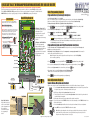
1
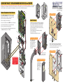
QUICKSTART “BASIC” INSTALLATION GUIDELINES FOR 1802 and 1802EPD
It is highly recommended that you consult the Installation/Owner’s manual for complete instructions on all the different types of installations. The 1802 Telephone
Entry System involves the installation of the 1802 enclosure and conduit runs for all necessary wiring (On reverse side). Be sure that all dirt, metal or wood debris is
removed from inside enclosure after mounting it. This could damage the control board and cause a malfunction during operation.
There are 2 different models of the 1802 telephone entry system Standard 1802 and 1802EPD which has an electronic programmable directory with scroll buttons. Components removal is the
same for the surface mount and flush mount units.
G1
86
2-0
10
Rib
Ca bon
ble
ON
MAS
CO TER
D
OFE
F
KE
MIC
4. Remove two locknuts from the faceplate hinge.
5. Remove the faceplate, main terminal (still wired) and store them in a
Safe Place until they need to be re-installed.
YP
AD
VO
L
FE
G
TO
N
OF E
F
HS
lS
G
re roun
Lo d
ckn
ut
.
.A
.S
U
K
I
E
CG
ND
PSW
MIC
G
MIC
NC
Ma
SPK
R
CO
M
C
NC
ina
NO
l
16A
C
C
N
D
A
IN
G
16A
C
T
S
W
O
P
O
E
D
N
n
t
a
te
E
E
N
L
G
P
A
T
IN
.,
E
R
C
IN
T
H
D
O
O
R
K
IN
G
O
7
7
2
3
5
1.
9
O
IN PER
0
L o STR AT
IN
ca
D te UC G
2 . ir e ct C o TIO
Pre o d e
N
ss ry
N S
1.
If Li C .
um
o
be
But ne is de N
ro
n
Tr ton Bus um
3. y A to H y, P ber.
En ga an re
ter in. g U ss
on
p. Any
To
ne
.
Su
rfa
ce
Mo
Install Enclosure
O
IN PER
ST A
5
8
0
9
Flu
un
sh
t
Mo
un
Mo
u
(No nting
t su Sc
pp rew
lied s
)
Mount ON a Surface
Wa
. in
Mfg
A.
S.
U.
one
ns
I
er ents.
e
utio
Dat
Sol 8
d undPat
I
K
ure S.
trol 194
No.
R
actng U.
O
Con ce
ent
O
Pat
ess Sin manufowi
Acc
t is foll
ducof the
e
s pro re
Dat
G
Thior mo
DIN
CA
No.
D
PEN
ent
OO
S
Pat
ENT
LEW
PAT
ING
.,
ER
INC
OTH
G
KIN
OR
DO
D
ll
t
Su
rf
M ace
En ount
clo
sur
e
1. Mount the enclosure using the mounting holes provided in the
corners. Be sure that mounting screws or nuts (Not supplied) do
not protrude into the enclosure where they could cause a short
on the back of the circuit board. Make any necessary conduit
connections through the back or bottom of the enclosure using
the existing conduit knock-outs.
2. Route all wiring through conduit and wire accordingly
(see reverse side for wiring).
3. Re-install components back into the enclosure.
Kn
Use appropriate
hardware to secure
enclosure to the wall
(not supplied).
DOORKING
Inglewood, Ca 90301
Model # 1800 Series
Serial #
Complies F.C.C. Part 68
F.C.C. Registration #
OUTDOOR USE / WET
DUF6VT-12874-OT-T
Ringer Equiv. 0.0A
CONFORMS TO UL STD 294
Jack USOC RJ11C or W
There are different styles
of DoorKing mounting
posts. All mounting posts
need the adapter plate
(P/N 1802-111) to mount
the 1802. Surface mount
models ONLY.
Ad
ap
Pla ter
te
Kn
ock
Use hardware supplied with
mounting post and adapter
plate to secure enclosure.
Discharge any static
BEFORE removing
the circuit board by
touching a proper
ground device.
Conduit run
to junction box
Su
rf
M ace
En ount
clo
sur
e
ACCESS CONTROL
SYSTEM UNITS
Fac
Hineplat
Lo ge e
ckn
uts
U.S.A.
6
Lo
ca R TIN
D te UC G
2 . ir e ct C o TIO
Pre o d e
N
ry
If Liss C . N u mS
o
be
But ne is de N
ro
n
Tr ton Bus um
3. y A to H y, P ber.
En ga an re
ter in. g U ss
on
p. Any
To
ne
.
6
8
Mount to a Mounting Post
in T
erm
BAT
I
P
2
180ace
f
r
Su unt e
o
M sur
lo
Enc
4
ock
-ou
ts
C
D
M
fg
.
in
T
h
A O
o is
cc O
r p
e
m r
ss
o od
re u
C
o ct Sin on N
f is
th
®
c tr
o
e m e ol
.
fo an 19 So
D
ll u 4 lu N
a
o fa 8 ti C
te
w c
o
in tu
n
s
g re
U d
. u
S n
. d
P
P e
a
a r
te
te o
n
n ne
t
ts
N
.
o
.
D
a
te
R
NO
w
ON
Wi
HF
cre
PH
CK
SP
VOK
L
RIN
ina
.
BA
NE
ON
in T
erm
,
ED
TO
Ma
G
THIS SIDE UP
3. Unscrew main terminal and remove the ground wire locknut.
1810-075 sn XX
CL
SECK
NS
E
0000010100010
1. Disconnect cable(s) from the circuit board.
2. Unscrew 1 circuit board screw and GENTLY remove the circuit board.
1
Cir
c
Sc uit Bo
rew ar
d
.
S
Bu croll
tto
Co Cabns
nn le
18 ecto
02 r
E
ONPD
LY
KIN
C
OR
N
DO
,
ST
®
Remove Components from Enclosure
RA
120 Glasgow Avenue
Inglewood, California 90301
3
G
NT
2
N
4
DOORKING
Inglewood, Ca 90301
Model # 1800 Series
ACCESS CONTROL
Serial #
SYSTEM UNITS
Complies F.C.C. Part 68
F.C.C. Registration #
OUTDOOR USE / WET
DUF6VT-12874-OT-T
Ringer Equiv. 0.0A
CONFORMS TO UL STD 294
Jack USOC RJ11C or W
1
CO
-ou
ts
Conduit
sweep run
Examples of conduit runs that may be used, depending on how
you choose to run the wiring. Some installations will allow the
conduit to be run outside the wall and connect to the bottom of the
enclosure but this is generally NOT recommended.
D
O
PA
O
RT
R
K
NU
IN
MBE
R
G®
,
IN
C
.
MAD
IN E
US
A
RE
Fac
V
SE
RI
AL
NO
.
ep
lat
e
Run all wires
inside post.
un
tin
(Su g Sc
pp rew
lied s
)
Mount IN a Surface
Wa
ll
Mount in a DoorKing Kiosk
DoorKing offers a
self-standing lighted
kiosk for the flush
mount unit ideal for
walk-up pedestrian
applications
(P/N 1200-160).
Mo
Flu
sh
En Mou
clo nt
sur
e
Ro
ug
h
Bo -In
x
QUICKSTART “BASIC” WIRING AND PROGRAMMING GUIDELINES FOR 1802 AND 1802EPD
It is highly recommended that you consult the Installation/Owner’s manual for complete instructions on all wiring and programming.
The 1802 needs wiring to an incoming telephone line, power wiring, connection to a entry door or gate and it MUST be properly grounded.
The 1802 MUST have DIRECTORY CODES programmed into it to be able to contact the residents from the system. The resident will be able to
GRANT ACCESS and open the door or gate by pressing “9” on their phone or DENY ACCESS by pressing “#” on their phone.
Basic Wiring Required
MASTER CODE
The 1802 is programmed from the factory with “9 9 9 9” as
the default “Master Code”. It can be re-programmed if desired.
CONTRAST
DOORKING 1862-010
Switch OFF - Normal operating mode positon.
LCD Display - Welcome Note: The
welcome message is factory set and
will probably need to be
re-programmed for your specific
needs. Refer to manual for
re-programming welcome message
if desired.
?
?
?
?
F
OF
MASTER
CODE
OFF
THIS SIDE UP
2. Choose and enter a four digit Master Code
number, then press “*”, “beep” will be heard.
ON
1810-075 sn XX
ON
(Write down your master code).
3. Turn Master Code switch OFF.
ON
0000010100010
Switch ON - After master code switch has been turned ON, system
will be in Master Code programming mode. (If master code switch
is turned ON and master code is not entered, the system will
sound a short tone after 30 seconds and continue every 30
seconds until master code is entered or switch is turned off).
1. Turn Master Code switch ON.
CLCK
SENSE
F
OF
KEYPAD
Microphone Adjust
120 Glasgow Avenue
Inglewood, California 90301
Program the Directory Code Length into System
U.S.A.
Set the directory code length to 1 - 2 - 3 or 4 digits.
If 11 or more residents are going to be programmed into the system, the directory code length must be at least two-digits.
If 101 or more residents are going to be programmed in, the directory code length must be at least three-digits.
The factory has already set this for three (3) digits but it can be changed if desired.
Master Code Switch Description
Re-Programming the “Master Code”
Basic Programming Required
LCD Display - 1802EPD ONLY Note:
The electronic programmable
display should have the resident
names programmed into it after the
directory codes have been
programmed in. Refer to manual for
programming names into the
1802EPD system.
ABC
1. Press
OPER
2
0
and enter your four-digit MASTER CODE ?
2. Enter the directory code digit length (1, 2, 3 or 4), then press
?
?
?
(beep). Note: Factory setting is “9999”.
(beep).
3. Press 0
(beep) to cancel this function, OR 1
(beeeeeep) to confirm the change.
SP
The programming sequence will automatically end itself after pressing 1
. This CANNOT be UNDONE!
OPER
SP
CAUTION: After programming this sequence, it is NOT recommended changing the directory code length.
Re-programming this sequence in the future will delete ALL phone numbers and directory codes that have
been previously programmed into the system.
Program Directory Codes and 7-Digit Phone Numbers into System
Program the directory codes and 7-digit phone numbers into the system. Be sure you have programmed the directory code
length before programming phone numbers.
Note: Directory code 0, 00, 000, 0000 should be used for management or an emergency phone number. Refer to manual for
more information about this specific directory code.
Note: If this telephone entry system is being used in an area that requires more or less than 7-digit dialing,
refer to manual for programming.
3 2 1
MIC VOL
FEEDBACK
Feedback Adjust
1. Press
3 2 1
Speaker Adjust
VOL
HF
RING
TONE
OFF
HS
NO NC
CGND PSW MICG MIC SPKR COM BAT
C
NC
NO 16AC 16AC
5. Press OPER
0
Power Input
16.5 VDC, 20 VA power.
Central Office
Phone Line Input
touch tone, loop start
Ferrite
Filter
Phone Line
Door Locks
Relay 1 Strike Time Note:
Relay 1 strike time is factory
set for 1 second. Strike time
can be re-programmed from
1/4 second up to 99
seconds. Refer to manual
for re-programming if
desired.
Power for electric strike or magnetic
lock is NOT provided by the system.
Use separate UL listed power supply.
Wire Size Distance
18 AWG Up to 100 ft
16 AWG Up to 200 ft
Wire polarity does not matter
“NO” - Normally Open (NO)
Earth Ground
“NC” - Normally Closed (NC)
1802 MUST be Properly Grounded!
“C” - Common (C)
?
?
Door Control
Door
Lock
Lock Power
UL listed
(beep). Note: Factory setting is “9999”.
(beep).
(beep).
Relay Input 1
Basic Adjustments Required
Speaker Volume, Microphone and Feedback
Speaker volume, microphone volume and feedback ALL interact with each other to affect the audio performance of the system.
3 2 1 SPK
Gate Control
3 2 1
MIC VOL
FEEDBACK
To Relay Input 1
?
together to end this programming sequence (beeeeeep).
VOL
Electric strike is wired
to Normally Open (NO)
relay input 1.
Magnetic lock is wired to
the Normally Closed (NC)
relay input 1.
and enter your four-digit MASTER CODE ?
4. Repeat steps 2 and 3 to enter additional directory codes and 7-digit phone numbers.
Note: The back of the manual contains log tables to record all of this information.
C
Main Terminal
PHONE
Wiring MUST be twisted and
completely isolated from ground.
1
3. Enter a seven-digit phone number for the chosen directory code, then press
Tone On/Off Jumper
Wire Size Distance
24 AWG Up to 800 ft
22 AWG Up to 1600 ft
SP
0
2. Choose and enter a directory code (1, 2, 3 or 4 digits, depending on what was programmed above), then press
3 2 1 SPK
TONE
ON
OPER
Gate Operator
To Relay Input 1
Gate Operator
is wired to
Normally Open
(NO) relay
input 1.
3 2 1
NE
TOON
Copyright 2014 DoorKing, Inc. All rights reserved.
NE
TO F
OF
1. Locate the speaker volume, microphone volume and feedback adjustments on circuit board. Place a phone call from
the telephone entry system to a resident using a resident’s directory code.
2. While they are talking, adjust the speaker volume for adequate sound.
3. Talk to the resident in a normal voice to adjust the microphone volume. Ask the resident to let you know when the
sound in their telephone is adequate.
4. After speaker and microphone have been adjusted, ask the resident to remain silent.
5. Remove the jumper from the TONE OFF terminals on the circuit board and place it on the TONE ON terminals. A tone
will be heard in the speaker.
6. Rotate the feedback adjustment. When the tone from the speaker is minimum, this is the correct adjustment.
7. Jumper MUST be moved back to the TONE OFF terminals when complete.
Note: High microphone and speaker volume levels may cause feedback. It may be necessary to reduce the
speaker volume if the microphone volume is set too high. Likewise, it may be necessary to reduce the
microphone volume if the speaker volume is set too high.
1802-066-A-5-14