1
SERVICE & MAINTENANCE
Models
1532E2
1932E2
2032E2
2632E2
2646E2
3246E2
3120855
May 10, 2006
INTRODUCTION - MAINTENANCE SAFETY PRECAUTIONS
SECTION A. INTRODUCTION - MAINTENANCE SAFETY
PRECAUTIONS
A.A GENERAL
This section contains the general safety precautions
which must be observed during maintenance of the
aerial platform. It is of utmost importance that maintenance personnel pay strict attention to these warnings and precautions to avoid possible injury to
themselves or others, or damage to the equipment.
A maintenance program must be followed to ensure
that the machine is safe to operate.
MODIFICATION OF THE MACHINE WITHOUT CERTIFICATION BY A RESPONSIBLE AUTHORITY THAT THE
MACHINE IS AT LEAST AS SAFE AS ORIGINALLY
MANUFACTURED, IS A SAFETY VIOLATION.
The specific precautions to be observed during
maintenance are inserted at the appropriate point in
the manual. These precautions are, for the most
part, those that apply when servicing hydraulic and
larger machine component parts.
Your safety, and that of others, is the first consideration when engaging in the maintenance of equipment. Always be conscious of weight. Never attempt
to move heavy parts without the aid of a mechanical
device. Do not allow heavy objects to rest in an
unstable position. When raising a portion of the
equipment, ensure that adequate support is provided.
Relieve system pressure by cycling the applicable
control several times with the engine stopped and
ignition on, to direct any line pressure back into the
reservoir. Pressure feed lines to system components
can then be disconnected with minimal fluid loss.
A.C MAINTENANCE
FAILURE TO COMPLY WITH SAFETY PRECAUTIONS
LISTED IN THIS SECTION MAY RESULT IN MACHINE
DAMAGE, PERSONNEL INJURY OR DEATH AND IS A
SAFETY VIOLATION.
• NO SMOKING IS MANDATORY. NEVER REFUEL DURING ELECTRICAL STORMS. ENSURE THAT FUEL CAP
IS CLOSED AND SECURE AT ALL OTHER TIMES.
• REMOVE ALL RINGS, WATCHES AND JEWELRY WHEN
PERFORMING ANY MAINTENANCE.
• DO NOT WEAR LONG HAIR UNRESTRAINED, OR
LOOSE-FITTING CLOTHING AND NECKTIES WHICH
ARE APT TO BECOME CAUGHT ON OR ENTANGLED
IN EQUIPMENT.
• OBSERVE AND OBEY ALL WARNINGS AND CAUTIONS ON MACHINE AND IN SERVICE MANUAL.
• KEEP OIL, GREASE, WATER, ETC. WIPED FROM
STANDING SURFACES AND HAND HOLDS.
• USE CAUTION WHEN CHECKING A HOT, PRESSURIZED COOLANT SYSTEM.
• NEVER WORK UNDER AN ELEVATED BOOM UNTIL
BOOM HAS BEEN SAFELY RESTRAINED FROM ANY
MOVEMENT BY BLOCKING OR OVERHEAD SLING,
OR BOOM SAFETY PROP HAS BEEN ENGAGED.
SINCE THE MACHINE MANUFACTURER HAS NO
DIRECT CONTROL OVER THE FIELD INSPECTION
AND MAINTENANCE, SAFETY IN THIS AREA RESPONSIBILITY OF THE OWNER/OPERATOR.
• BEFORE MAKING ADJUSTMENTS, LUBRICATING OR
PERFORMING ANY OTHER MAINTENANCE, SHUT OFF
ALL POWER CONTROLS.
• BATTERY SHOULD ALWAYS BE DISCONNECTED DURING REPLACEMENT OF ELECTRICAL COMPONENTS.
A.B HYDRAULIC SYSTEM SAFETY
It should be noted that the machines hydraulic systems operate at extremely high potentially dangerous pressures. Every effort should be made to
relieve any system pressure prior to disconnecting
or removing any portion of the system.
3120855
• KEEP ALL SUPPORT EQUIPMENT AND ATTACHMENTS
STOWED IN THEIR PROPER PLACE.
• USE ONLY APPROVED, NONFLAMMABLE CLEANING
SOLVENTS.
– JLG Sizzor –
a
INTRODUCTION - MAINTENANCE SAFETY PRECAUTIONS
REVISON LOG
Original Issue - June 1998
Revised - March 5, 1999 (Added 3246E2)
Revised - September 15, 1999 (Added 3246E2 w/
Proportional Control)
Revised
- April 17, 2001
Revised
-
January 16, 2002
Revised
-
April 25, 2002
May 15, 2002 - Revised
August 26, 2003 - Revised
June 25, 2004 - Revised
November 8, 2004 - Revised
May 10, 2006 - Revised
b
– JLG Sizzor –
3120855
TABLE OF CONTENTS
TABLE OF CONTENTS
SUBJECT - SECTION, PARAGRAPH
PAGE NO.
SECTION A - INTRODUCTION - MAINTENANCE SAFETY PRECAUTIONS
A.A
A.B
A.C
General . . . . . . . . . . . . . . . . . . . . . . . . . . . . . . . . . . . . . . . . . . . . . . . . . . . . . . . . . . . . . . . . . . . . . .a-a
Hydraulic System Safety . . . . . . . . . . . . . . . . . . . . . . . . . . . . . . . . . . . . . . . . . . . . . . . . . . . . . . . . .a-a
Maintenance . . . . . . . . . . . . . . . . . . . . . . . . . . . . . . . . . . . . . . . . . . . . . . . . . . . . . . . . . . . . . . . . . .a-a
SECTION 1 - SPECIFICATIONS
1.1
1.2
1.3
1.4
1.5
1.6
1.7
1.8
1.9
1.10
1.11
Capacities . . . . . . . . . . . . . . . . . . . . . . . . . . . . . . . . . . . . . . . . . . . . . . . . . . . . . . . . . . . . . . . . . . . .1-1
Component Data . . . . . . . . . . . . . . . . . . . . . . . . . . . . . . . . . . . . . . . . . . . . . . . . . . . . . . . . . . . . . . .1-1
Performance Data . . . . . . . . . . . . . . . . . . . . . . . . . . . . . . . . . . . . . . . . . . . . . . . . . . . . . . . . . . . . . .1-1
Torque Requirements . . . . . . . . . . . . . . . . . . . . . . . . . . . . . . . . . . . . . . . . . . . . . . . . . . . . . . . . . . .1-3
Lubrication. . . . . . . . . . . . . . . . . . . . . . . . . . . . . . . . . . . . . . . . . . . . . . . . . . . . . . . . . . . . . . . . . . . .1-3
Serial Number Locations. . . . . . . . . . . . . . . . . . . . . . . . . . . . . . . . . . . . . . . . . . . . . . . . . . . . . . . . .1-4
Limit Switches . . . . . . . . . . . . . . . . . . . . . . . . . . . . . . . . . . . . . . . . . . . . . . . . . . . . . . . . . . . . . . . . .1-4
Cylinder Specifications . . . . . . . . . . . . . . . . . . . . . . . . . . . . . . . . . . . . . . . . . . . . . . . . . . . . . . . . . .1-4
Pressure Settings . . . . . . . . . . . . . . . . . . . . . . . . . . . . . . . . . . . . . . . . . . . . . . . . . . . . . . . . . . . . . .1-5
Critical Stability Weights . . . . . . . . . . . . . . . . . . . . . . . . . . . . . . . . . . . . . . . . . . . . . . . . . . . . . . . . .1-5
Major Component Weights . . . . . . . . . . . . . . . . . . . . . . . . . . . . . . . . . . . . . . . . . . . . . . . . . . . . . . .1-5
SECTION 2 - PROCEDURES
2.1
2.2
2.3
2.4
2.5
2.6
2.7
2.8
2.9
2.10
2.11
2.12
2.13
2.14
2.15
2.16
2.17
2.18
2.19
2.20
2.21
2.22
2.23
General . . . . . . . . . . . . . . . . . . . . . . . . . . . . . . . . . . . . . . . . . . . . . . . . . . . . . . . . . . . . . . . . . . . . . .2-1
Servicing and Maintenance Guidelines . . . . . . . . . . . . . . . . . . . . . . . . . . . . . . . . . . . . . . . . . . . . .2-1
Lubrication Information . . . . . . . . . . . . . . . . . . . . . . . . . . . . . . . . . . . . . . . . . . . . . . . . . . . . . . . . . .2-2
Cylinders - Theory of Operation . . . . . . . . . . . . . . . . . . . . . . . . . . . . . . . . . . . . . . . . . . . . . . . . . . .2-3
Valves - Theory of Operation. . . . . . . . . . . . . . . . . . . . . . . . . . . . . . . . . . . . . . . . . . . . . . . . . . . . . .2-3
Component Functional Description . . . . . . . . . . . . . . . . . . . . . . . . . . . . . . . . . . . . . . . . . . . . . . . .2-4
Wear Pads . . . . . . . . . . . . . . . . . . . . . . . . . . . . . . . . . . . . . . . . . . . . . . . . . . . . . . . . . . . . . . . . . . . .2-4
Cylinder Checking Procedures . . . . . . . . . . . . . . . . . . . . . . . . . . . . . . . . . . . . . . . . . . . . . . . . . . . .2-4
Lift Cylinder Removal and Installation. . . . . . . . . . . . . . . . . . . . . . . . . . . . . . . . . . . . . . . . . . . . . . .2-5
Lift Cylinder Repair . . . . . . . . . . . . . . . . . . . . . . . . . . . . . . . . . . . . . . . . . . . . . . . . . . . . . . . . . . . . .2-5
Brake Cylinder Repair . . . . . . . . . . . . . . . . . . . . . . . . . . . . . . . . . . . . . . . . . . . . . . . . . . . . . . . . . . .2-9
Steer Cylinder Repair . . . . . . . . . . . . . . . . . . . . . . . . . . . . . . . . . . . . . . . . . . . . . . . . . . . . . . . . . . .2-10
Tilt Switch Adjustment . . . . . . . . . . . . . . . . . . . . . . . . . . . . . . . . . . . . . . . . . . . . . . . . . . . . . . . . . . .2-12
Pressure Setting procedures . . . . . . . . . . . . . . . . . . . . . . . . . . . . . . . . . . . . . . . . . . . . . . . . . . . . .2-14
Limit Switch Adjustment . . . . . . . . . . . . . . . . . . . . . . . . . . . . . . . . . . . . . . . . . . . . . . . . . . . . . . . . .2-18
Door Adjustment . . . . . . . . . . . . . . . . . . . . . . . . . . . . . . . . . . . . . . . . . . . . . . . . . . . . . . . . . . . . . . .2-18
JLG SMART System™ Analyzer Kit Instructions . . . . . . . . . . . . . . . . . . . . . . . . . . . . . . . . . . . . . . .2-18
Machine Personality Settings . . . . . . . . . . . . . . . . . . . . . . . . . . . . . . . . . . . . . . . . . . . . . . . . . . . . .2-21
Machine Model Default Settings . . . . . . . . . . . . . . . . . . . . . . . . . . . . . . . . . . . . . . . . . . . . . . . . . .2-23
Machine Configuration Information. . . . . . . . . . . . . . . . . . . . . . . . . . . . . . . . . . . . . . . . . . . . . . . . .2-24
Jlg Smart System™ Help Messages and Flash Codes . . . . . . . . . . . . . . . . . . . . . . . . . . . . . . . . .2-26
Analyzer Menu Structure. . . . . . . . . . . . . . . . . . . . . . . . . . . . . . . . . . . . . . . . . . . . . . . . . . . . . . . . .2-29
Preventive Maintenance and Inspection Schedule. . . . . . . . . . . . . . . . . . . . . . . . . . . . . . . . . . . . .2-35
SECTION 3 - TROUBLESHOOTING
3.1
3.2
3.3
3120855
General . . . . . . . . . . . . . . . . . . . . . . . . . . . . . . . . . . . . . . . . . . . . . . . . . . . . . . . . . . . . . . . . . . . . . .3-1
Troubleshooting Information. . . . . . . . . . . . . . . . . . . . . . . . . . . . . . . . . . . . . . . . . . . . . . . . . . . . . .3-1
Hydraulic Circuit Checks. . . . . . . . . . . . . . . . . . . . . . . . . . . . . . . . . . . . . . . . . . . . . . . . . . . . . . . . .3-1
– JLG Sizzor –
i
TABLE OF CONTENTS (Continued)
LIST OF FIGURES
FIGURE NO.
1-1.
1-2.
2-1.
2-2.
2-3.
2-4.
2-5.
2-7.
2-8.
2-9.
2-10.
2-11.
2-12.
2-13.
2-14.
2-15.
3-1.
3-2.
3-3.
3-4.
3-5.
3-6.
3-7.
3-8.
TITLE
PAGE NO.
Serial Number Location. . . . . . . . . . . . . . . . . . . . . . . . . . . . . . . . . . . . . . . . . . . . . . . . . . . . . . . . . .1-4
Torque Chart. . . . . . . . . . . . . . . . . . . . . . . . . . . . . . . . . . . . . . . . . . . . . . . . . . . . . . . . . . . . . . . . . .1-6
Lift Cylinder Assembly. . . . . . . . . . . . . . . . . . . . . . . . . . . . . . . . . . . . . . . . . . . . . . . . . . . . . . . . . . .2-6
Barrel Support . . . . . . . . . . . . . . . . . . . . . . . . . . . . . . . . . . . . . . . . . . . . . . . . . . . . . . . . . . . . . . . . .2-6
Capscrew Removal . . . . . . . . . . . . . . . . . . . . . . . . . . . . . . . . . . . . . . . . . . . . . . . . . . . . . . . . . . . . .2-7
Rod Support . . . . . . . . . . . . . . . . . . . . . . . . . . . . . . . . . . . . . . . . . . . . . . . . . . . . . . . . . . . . . . . . . .2-7
Rod Seal Installation . . . . . . . . . . . . . . . . . . . . . . . . . . . . . . . . . . . . . . . . . . . . . . . . . . . . . . . . . . . .2-8
Brake Cylinder Assembly . . . . . . . . . . . . . . . . . . . . . . . . . . . . . . . . . . . . . . . . . . . . . . . . . . . . . . . .2-9
Steer Cylinder Assembly . . . . . . . . . . . . . . . . . . . . . . . . . . . . . . . . . . . . . . . . . . . . . . . . . . . . . . . . .2-11
Tilt Switch Leveling Manual Adjustment . . . . . . . . . . . . . . . . . . . . . . . . . . . . . . . . . . . . . . . . . . . . .2-13
Tilt Switch Leveling Voltmeter Adjustment . . . . . . . . . . . . . . . . . . . . . . . . . . . . . . . . . . . . . . . . . . .2-13
Control Valve Components . . . . . . . . . . . . . . . . . . . . . . . . . . . . . . . . . . . . . . . . . . . . . . . . . . . . . . .2-14
Control Valve Components (3246E2 w/Proportional Control) . . . . . . . . . . . . . . . . . . . . . . . . . . . .2-16
Quick Welder™ Installation . . . . . . . . . . . . . . . . . . . . . . . . . . . . . . . . . . . . . . . . . . . . . . . . . . . . . . .2-17
JLG SMART System™ Controller . . . . . . . . . . . . . . . . . . . . . . . . . . . . . . . . . . . . . . . . . . . . . . . . . .2-18
Organizational Chart . . . . . . . . . . . . . . . . . . . . . . . . . . . . . . . . . . . . . . . . . . . . . . . . . . . . . . . . . . . .2-22
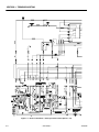
Electrical Schematic - Non Proportional Control (Sheet 1 of 2) . . . . . . . . . . . . . . . . . . . . . . . . . . .3-4
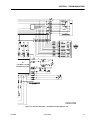
Electrical Schematic - Non Proportional Control (Sheet 2 of 2) . . . . . . . . . . . . . . . . . . . . . . . . . . .3-5
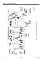
Electrical Schematic - Proportional Control (Sheet 1 of 2). . . . . . . . . . . . . . . . . . . . . . . . . . . . . . .3-6
Electrical Schematic - Proportional Control (Sheet 2 of 2). . . . . . . . . . . . . . . . . . . . . . . . . . . . . . .3-7
Hydraulic Schematic - Non Proprtional Drive . . . . . . . . . . . . . . . . . . . . . . . . . . . . . . . . . . . . . . . . .3-8
Hydraulic Schematic - 3246E2 Proprtional Control . . . . . . . . . . . . . . . . . . . . . . . . . . . . . . . . . . . .3-9
Harness and Cable Assembly - Non Proportional Control (Sheet 1 of 2) . . . . . . . . . . . . . . . . . . .3-10
Harness and Cable Assembly - Non Proportional Control (Sheet 2 of 2) . . . . . . . . . . . . . . . . . . .3-11
LIST OF TABLES
TABLE NO.
1-1
1-2
1-3
1-4
1-5
1-6
2-1
2-2
2-3
2-4
2-5
2-6
2-7
2-8
2-9
2-10
3-1
3-2
ii
TITLE
PAGE NO.
Torque Requirements . . . . . . . . . . . . . . . . . . . . . . . . . . . . . . . . . . . . . . . . . . . . . . . . . . . . . . . . . . .1-3
Hydraulic Oil . . . . . . . . . . . . . . . . . . . . . . . . . . . . . . . . . . . . . . . . . . . . . . . . . . . . . . . . . . . . . . . . . .1-3
Lubrication Specifications . . . . . . . . . . . . . . . . . . . . . . . . . . . . . . . . . . . . . . . . . . . . . . . . . . . . . . . .1-3
Cylinder Specifications . . . . . . . . . . . . . . . . . . . . . . . . . . . . . . . . . . . . . . . . . . . . . . . . . . . . . . . . . .1-4
Critical Stability Weights . . . . . . . . . . . . . . . . . . . . . . . . . . . . . . . . . . . . . . . . . . . . . . . . . . . . . . . . .1-5
Major Component Weights . . . . . . . . . . . . . . . . . . . . . . . . . . . . . . . . . . . . . . . . . . . . . . . . . . . . . . .1-5
Cylinder Component Torque Specifications. . . . . . . . . . . . . . . . . . . . . . . . . . . . . . . . . . . . . . . . . .2-8
Holding Valve Torque Specifications. . . . . . . . . . . . . . . . . . . . . . . . . . . . . . . . . . . . . . . . . . . . . . . .2-8
Pressure Settings Chart . . . . . . . . . . . . . . . . . . . . . . . . . . . . . . . . . . . . . . . . . . . . . . . . . . . . . . . . .2-15
Machine Personality Settings . . . . . . . . . . . . . . . . . . . . . . . . . . . . . . . . . . . . . . . . . . . . . . . . . . . . .2-21
Machine Model Default Settings Chart . . . . . . . . . . . . . . . . . . . . . . . . . . . . . . . . . . . . . . . . . . . . . .2-23
Machine Configuration Programming Information . . . . . . . . . . . . . . . . . . . . . . . . . . . . . . . . . . . . .2-24
Help Messages . . . . . . . . . . . . . . . . . . . . . . . . . . . . . . . . . . . . . . . . . . . . . . . . . . . . . . . . . . . . . . . .2-26
JLG SMART System™ Flash Codes & Help Messages . . . . . . . . . . . . . . . . . . . . . . . . . . . . . . . . .2-27
Analyzer Menu Structure. . . . . . . . . . . . . . . . . . . . . . . . . . . . . . . . . . . . . . . . . . . . . . . . . . . . . . . . .2-29
Preventive Maintenance and Inspection Schedule . . . . . . . . . . . . . . . . . . . . . . . . . . . . . . . . . . . .2-36
Electricl Troubleshooting Chart . . . . . . . . . . . . . . . . . . . . . . . . . . . . . . . . . . . . . . . . . . . . . . . . . . .3-2
Hydraulic System Troubleshooting Chart. . . . . . . . . . . . . . . . . . . . . . . . . . . . . . . . . . . . . . . . . . . .3-3
– JLG Sizzor –
3120855
SECTION 1 - SPECIFICATIONS
SECTION 1. SPECIFICATIONS
1.1
Drive Motors
CAPACITIES
1932E2 - 126 cm3 displacement
Hydraulic Oil Tank
2032E2 - 229.4 cm3 displacement
1932E2
2632E2 - 310.3 cm3 displacement
11.4 liters at full mark on tank
2646E2 - 265.5 cm3 displacement
9.5 liters at add mark on tank
2032E2/2632E2/2646E2/3246E2
3246E2 - 294 cm3 displacement
14.8 liters at full mark on tank
Hydraulic Filter - Inline
12.9 liters at add mark on tank
Return - Bypass Type
Hydraulic System (Including Tank)
10 Microns Nominal
1932E2 - Approximately 15.0 liters
2032E2/2632E2/2646E2/3246E2 - Approximately 19.0
liters
Platform Size
1932E2 - 0.8 m x 1.6 m
2032E2/2632E2 - 0.8 m x 2.1 m
1.2
COMPONENT DATA
2646E2/3246E2 - 1.1 m x 2.1 m
Hydraulic Pump/Electric Motor Assembly
1.3
24 Volts DC motor w/Single section gear pump
1932E2 8.5 lpm
PERFORMANCE DATA
Travel Speed
2032E2/2632E2/2646E2/3246E2 -11.4 lpm
1932E2
Battery Charger
Low Speed - 2.1 kmh
20 Amp SCR
Elevated Speed -1.1 kmh
120/240 Volts AC - 50 Hz input
Maximum Speed - 4.0 kmh
24 Volts DC - 20 Amp output w/auto timer
2032E2
Batteries (4)
Low Speed - 2.1 kmh
1932E2/2032E2/2646E2 - 6 Volt, 220 Amp Hour
Elevated Speed - 1.1 kmh
2632E2/3246E2 - 6 Volt, 245 Amp Hour
Maximum Speed - 4.2 kmh
Steer/Drive System
2632E2/2646E2
Tires -1932E2
Low Speed - 2.1 kmh
Standard - 12.5 x 4 - Solid, Non-Marking, Rib
Optional - 12.5x4 - Solid, Rib
Elevated Speed - 1.1 kmh
Tires - 2032E2/2632E2/2646E2/3246E2
Maximum Speed - 3.6 kmh
Standard - 16.00 x 5.00 - Solid, Non-Marking
3246E2
Optional -16.00 x 5.00 - Solid, Rib
Low Speed - 2.1 kmh
Parking Brake ( rear dual wheel) - Single cylinder, spring
applied, hydraulically released.
Elevated Speed - 0.8 kmh
Maximum Speed - 3.2 kmh
3120855
– JLG Sizzor –
1-1
SECTION 1 - SPECIFICATIONS
Gradeability
Machine Weight
All Models - 25%
1932E2 - approx. 1360 kg
Inside Turning Radius
1932E2 - 0.5 m
2032E2/2632E2 - 1m
2032E2 - approx. 2091 kg
2632E2 - approx. 2415 kg
2646E2 - approx. 2086 kg
3246E2 - approx. 2812 kg
2646E2 - 1 m
3246E2 - 1.1 m
Wheelbase
1932E2 -1.3 m
Lift (No Load in Platform)
2032E2/2632E2/2646E2/3246E2 - 1.7 m
1932E2
Up - 27 seconds
Platform Height (Elevated)
1932E2 - 5.8 m
Down -26 seconds
2032E2 - 6.1 m
2032E2
2632E2/2646E2 - 7.9 m
Up - 27-35 seconds
3246E2 - 9.75 m
Down - 28-35 seconds
2632E2
Platform Height (Stowed)
1932E2 - 1.0 m
Up - 34-42 seconds
2032E2 - 1.0 m
Down - 39-47 seconds
2646E2/3246E2 - 1.2 m
2646E2
Up - 40-48 seconds
Machine Height (Stowed)
Standard Handrails
Down - 37-45 seconds
1932E2 - 2.0 m
3246E2
2032E2 - 2.0 m
Up - 56-64 seconds
Down - 45-55 seconds
Platform Capacity
1932E2 - 230 kg
2033E2 - 340 kg
2632E2 - 230 kg
2646E2 - 340 kg
3246E2 - 320 kg
2632E2 - 1.2 m
2646E2 - 1.8 m
3246E2 - 2.3 m
Machine Length
1932E2 - 1.7 m
2032E2/2632E2/2646E2/3246E2 - 2.3 m
Machine Width
1932E2 - 0.8 m
Manual Platform Extension Capacity
2032E2 - 0.8 m
All Models - 120 kg. - 1 person
2646E2/3246E2 -1.2 m
1-2
– JLG Sizzor–
3120855
SECTION 1 - SPECIFICATIONS
Ground Clearance
1.5
LUBRICATION
With Platform Lowered
Hydraulic Oil
All Models - 8.0 cm
With Platform Elevated
Table 1-2. Hydraulic Oil
(Pothole Protection System Lowered)
HYDRAULIC SYSTEM
OPERATING TEMPERATURE
RANGEc
All Models - 1.9 cm
Maximum Tire Load
1932E2 - 492 kg
2032E2 - 662 kg
2632E2 - 885 kg
2646E2 - 746 kg
Maximum Bearing Pressure
1932E2 - 6.4 kg/cm2
2032E2 - 7.0 kg/cm2
2632E2 - 8.4 kg/cm2
10W
0o F to + 210o F
(-18o C to +99o C)
10W-20, 10W-30
50o F to + 210o F
(+10o C to + 210o C)
20W-20
NOTE: Aside from JLG recommendations, it is not advisable
to mix oils of different brands or types, as they may
not contain the same required additives or be of
comparable viscosities. If use of hydraulic oil other
than Mobilfluid 424 is desired, contact JLG Industries for proper recommendations.
2646E2 - 7.5 kg/cm2
3246E2 - 8.9 kg/cm2
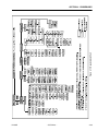
TORQUE REQUIREMENTS
Lubrication Specifications
Table 1-1. Torque Requirements
Desriciption
0o F to + 23o F
(-18o C to -5o C)
NOTE: Hydraulic oils must have anti-wear qualities at least
to API Service Classification GL-3, and sufficient
chemical stability for mobile hydraulic system service. JLG Industries recommends Mobilfluid 424
hydraulic oil, which has an SAE viscosity of 10W-30
and a viscosity index of 152. When temperatures
remain consistently below 20° F (-7° C), JLG recommends the use of MobilDTE13M hydraulic oil.
3246E2 - 1,065 kg
1.4
SAE VISCOSITY GRADE
Table 1-3. Lubrication Specifications
Torque Value (Dry)
Interval Hours
KEY
SPECIFICATIONS
Wheel Lugs
105-120 ft lb (147-168 Nm)
50
MPG
Wheel Hub To Drive
Motor
125-150 ft lb* (169-203 Nm)
600
Multipurpose Grease having a minimum dripping
point of 350o F. Excellent water resistance and
adhesive qualities, and being of extreme pressure type. (Timken OK 40 pounds minimum
EPGL
Extreme Pressure Gear Lube (oil) meeting API
service classification GL-5 or MIL-Spec MIL-L2105
Torque nut to 169 -203 Nm (dry), then add extra torque to
line up the slot with the hole in the shaft to install the cotter
pin.
NOTE: When maintenance becomes necessary or a fastener has loosened, to determine proper torque
value, refer to Figure 1-2., Torque Chart.
3120855
– JLG Sizzor –
HO
Hydraulic Oil. API service classification GL-3,e.g.
Mobilfluid 424 .
1-3
SECTION 1 - SPECIFICATIONS
1.6
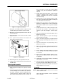
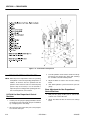
SERIAL NUMBER LOCATIONS
1.8
For machine identification, a serial number plate is affixed
to the machine. On 2032E2/2632E2/2646E2 and 3246E2
the plate is located on the front, center of the machine
frame, on 1932E2 it is located above the right rear tire. The
serial number will also be stamped on the front center of
the machine frame.
CYLINDER SPECIFICATIONS
NOTE: All dimensions are given in inches (in), with the metric equivalent, centimeters (cm), given in parenthe
ses.
Table 1-4. Cylinder Specifications
Description
Bore
Stroke
Rod Diameter
Lift Cylinder
(1932E2)
3.00
(7.6)
32.00
(81.2)
2.00
(5.1)
The machines are equipped with the following limit
switches:
Lift Cylinder
(2032E2)
3.50
(8.9)
38.87
(98.7)
2.00
(5.1)
Tilt Alarm - Illuminates a light on the platform and sounds
an alarm when the machine is elevated and out of level in
any direction 2° or more.
Lift Cylinder
(2632E2)
3.50
(8.9)
38.94
(99.0)
2.00
(5.1)
Lift Cylinder
(2646E2)
3.00
(7.6)
37.75
(95.8)
2.00
(5.1)
Lift Cylinder
(3246E2)
3.5
(8.9)
38.94
(99.0)
2.00
(5.1)
Steer Cylinder
(All Models)
1.50
(3.8)
6.25
(15.9)
0.75
(1.9)
2.00
(5.1)
1.75
(4.4)
1.00
(2.5)
1.7
LIMIT SWITCHES
High Drive Cut-Out - High drive speed is cut out when the
platform is raised above the preset height per model as
follows.
1932E2 - 2.6 m
2032E2 - 2.1 m
2632E2 (Australian Only) - 2.9 m
Brake Cylinder
(All Models)
2632E2/2646E2 - 2.6 m
3246E2 - 2.8 m
Figure 1-1. Serial Number Location
1-4
– JLG Sizzor–
3120855
SECTION 1 - SPECIFICATIONS
1.9
PRESSURE SETTINGS
1.11 MAJOR COMPONENT WEIGHTS
Table 1-6. Major Component Weights
Pressure Settings for Non Proportional
Control Machines
COMPONENT
KG
LB
Platform (31 in. x 62 in.) - 1932E2
113
250
Platform (31 in. x84 in.) - 2032E2/2632E2
176
388
Platform (46in. x 84 in.) - 2646E2/3246E2
204
450
Lift Up Relief Max -
Manual Platform Extension -1932E2
71
156
1932E2 - 159 bar
Manual Platform Extension -2032E2/2632E2
71
156
Main Relief Max - 221 bar
Steer Relief Max - 138 bar
2033E2 - 152 bar
2632E2/2646E2/3246E2 - 165 bar
Pressure Settings for Proportional Control
Machines
Main Relief Max - 207 bar +3.4/-0 bar (3000 psi +50/-0
psi)
Steer Relief Max - 145 bar (2100 psi)
Manual Platform Extension -2646E2/3246E2
98
215
Arm Assembly - 1932E2 (Includes Lift Cylinder)
279
616
Arm Assembly - 2032E2 (Includes Lift Cylinder)
477
1,052
Arm Assembly - 2632E2 (Includes Lift Cylinder)
3,380
1,535
Arm Assembly - 2646E2 (Includes Lift Cylinder)
787
1,736
Arm Assembly - 3246E2 (Includes Lift Cylinder)
980
2,156
Chassis - 1932E2 w/Solid Tires
798
1,760
1,054
2,324
Chassis - 2646E2 w/Solid Tires
876
1,932
Chassis - 3246E2 w/Solid Tires
1,022
2,253
Chassis - 2032E2 w/Solid Tires
(Includes 464 lb[211 kg] Counterweight)
Lift Up Relief Max - 145 bar (2100 psi)
1.10 CRITICAL STABILITY WEIGHTS
DO NOT REPLACE ITEMS CRITICAL TO STABILITY, SUCH AS
BATTERIES OR SOLID TIRES, WITH ITEMS OF DIFFERENT
WEIGHT OR SPECIFICATION. DO NOT MODIFY UNIT IN ANY WAY
TO AFFECT STABILITY.
Table 1-5. Critical Stability Weights
Component
1932E2
Tires-Solid
(each)
24lb
(11kg)
31 lb
(14 kg)
31 lb
(14 kg)
Tires-Solid-NonMarking (each)
24lb
(11kg)
30 lb
(14 kg)
30 lb
(14 kg)
Motor/Pump Assembly
41 lb
(19 kg)
41 lb
(19 kg)
41 lb
(19 kg)
Batteries - Std.- Each
63 lb
(29 kg)
63 lb
(29 kg)
63 lb
(29 kg)
Batteries - Standard Combined
252 lb
(114 kg)
252 lb
(114 kg)
252 lb
(114 kg)
3120855
2032E2/2632E2 2646E2/3246E2
– JLG Sizzor –
1-5
SECTION 1 - SPECIFICATIONS
Figure 1-2. Torque Chart.
1-6
– JLG Sizzor–
3120855
SECTION 2 - PROCEDURES
SECTION 2. PROCEDURES
2.1
items must be maintained on a scheduled basis in
order to function properly.
GENERAL
This section provides information necessary to perform
maintenance on the scissor lift. Descriptions, techniques
and specific procedures are designed to provide the safest and most efficient maintenance for use by personnel
responsible for ensuring the correct installation and operation of machine components and systems.
NOTE: Maintenance procedures provided in this section
apply to all scissor lift models covered in this manual.
Procedures that apply to a specific model will be so
noted.
WHEN AN ABNORMAL CONDITION IS NOTED AND PROCEDURES
CONTAINED HEREIN DO NOT SPECIFICALLY RELATE TO THE
NOTED IRREGULARITY, WORK SHOULD BE STOPPED AND
TECHNICALLY QUALIFIED GUIDANCE OBTAINED BEFORE WORK
IS RESUMED.
The maintenance procedures included consist of servicing and component removal and installation, disassembly
and assembly, inspection, lubrication and cleaning. Information on any special tools or test equipment is also provided where applicable.
2.2
SERVICING AND MAINTENANCE
GUIDELINES
General
The following information is provided to assist you in the
use and application of servicing and maintenance procedures contained in this chapter.
Safety and Workmanship
Your safety, and that of others, is the first consideration
when engaging in the maintenance of equipment. Always
be conscious of weight. Never attempt to move heavy
parts without the aid of a mechanical device. Do not allow
heavy objects to rest in an unstable position. When raising
a portion of the equipment, ensure that adequate support
is provided.
Cleanliness
1. The most important single item in preserving the
long service life of a machine is to keep dirt and foreign materials out of the vital components. Precautions have been taken to safeguard against this.
Shields, covers, seals, and filters are provided to
keep air, fuel, and oil supplies clean; however, these
3120855
2. At any time when air, fuel, or oil lines are disconnected, clear adjacent areas as well as the openings
and fittings themselves. As soon as a line or component is disconnected, cap or cover all openings to
prevent entry of foreign matter.
3. Clean and inspect all parts during servicing or maintenance, and assure that all passages and openings
are unobstructed. Cover all parts to keep them
clean. Be sure all parts are clean before they are
installed. New parts should remain in their containers until they are ready to be used.
Components Removal and Installation
1. Use adjustable lifting devices, whenever possible, if
mechanical assistance is required. All slings (chains,
cables, etc.) should be parallel to each other and as
near perpendicular as possible to top of part being
lifted.
2. Should it be necessary to remove a component on
an angle, keep in mind that the capacity of an eyebolt or similar bracket lessens, as the angle between
the supporting structure and the component
becomes less than 90°.
3. If a part resists removal, check to see whether all
nuts, bolts, cables, brackets, wiring, etc., have been
removed and that no adjacent parts are interfering.
Component Disassembly and Reassembly
When disassembling or reassembling a component, complete the procedural steps in sequence. Do not partially
disassemble or assemble one part, then start on another.
Always recheck your work to assure that nothing has been
overlooked. Do not make any adjustments, other than
those recommended, without obtaining proper approval.
Pressure Washing
It is a good practice to avoid pressure washing electronic
components. Should pressure washing be utilized to
wash areas containing electronic components, JLG Industries Inc. recommends a maximum pressure of 52 bar at a
minimum distance of 30.5 cm. away. In addition, JLG
Industries Inc. also recommends that these components
are indirectly sprayed for brief time periods to avoid saturation.
– JLG Sizzor –
2-1
SECTION 2 - PROCEDURES
Pressure-Fit Parts
Hydraulic System
When assembling pressure-fit parts, use an anti-seize or
molybdenum disulfide base compound to lubricate the
mating surface.
1. Keep the system clean. If evidence of metal or rubber particles is found in the hydraulic system, drain
and flush the entire system.
Bearings
2. Disassemble and reassemble parts on clean work
surface. Clean all metal parts with non-flammable
cleaning solvent. Lubricate components, as
required, to aid assembly.
1. When a bearing is removed, cover it to keep out dirt
and abrasives. Clean bearings in nonflammable
cleaning solvent and allow to drip dry. Compressed
air can be used but do not spin the bearing.
2. Discard bearings if the races and balls (or rollers)
are pitted, scored, or burned.
3. If a bearing is found to be serviceable, apply a light
coat of oil and wrap it in clean (waxed) paper. Do not
unwrap reusable or new bearings until they are
ready to install.
4. Lubricate new or used serviceable bearings before
installation. When pressing a bearing into a retainer
or bore, apply pressure to the outer race. If the bearing is to be installed on a shaft, apply pressure to the
inner race.
Service applicable components with the amount, type,
and grade of lubricant recommended in this manual, at
the specified intervals. When recommended lubricants are
not available, consult your local supplier for an equivalent
that meets or exceeds the specifications listed.
Batteries
Clean batteries, using a non-metallic brush and a solution
of baking soda and water. Rinse with clean water. After
cleaning, thoroughly dry batteries and coat terminals with
an anti-corrosion compound.
Lubrication and Servicing
Components and assemblies requiring lubrication and
servicing are shown in Section 1.
Gaskets
Check that holes in gaskets align with openings in the
mating parts. If it becomes necessary to hand-fabricate a
gasket, use gasket material or stock of equivalent material
and thickness. Be sure to cut holes in the right location, as
blank gaskets can cause serious system damage.
Bolt Usage and Torque Application
1. Use bolts of proper length. A bolt which is too long
will bottom before the head is tight against its related
part. If a bolt is too short, there will not be enough
thread area to engage and hold the part properly.
When replacing bolts, use only those having the
same specifications of the original, or one which is
equivalent.
2. Unless specific torque requirements are given within
the text, standard torque values should be used on
heat-treated bolts, studs, and steel nuts, in accordance with recommended shop practices.
Hydraulic Lines and Electrical Wiring
Clearly mark or tag hydraulic lines and electrical wiring, as
well as their receptacles, when disconnecting or removing
them from the unit. This will assure that they are correctly
reinstalled.
2-2
Lubrication
2.3
LUBRICATION INFORMATION
Hydraulic System
1. The primary enemy of a hydraulic system is contamination. Contaminants enter the system by various
means, e.g., using inadequate hydraulic oil, allowing
moisture, grease, filings, sealing components, sand,
etc., to enter when performing maintenance, or by
permitting the pump to cavitate due to insufficient
system warm-up or leaks in the pump supply (suction) lines.
2. The design and manufacturing tolerances of the
component working parts are very close, therefore,
even the smallest amount of dirt or foreign matter
entering a system can cause wear or damage to the
components and generally results in faulty operation. Every precaution must be taken to keep
hydraulic oil clean, including reserve oil in storage.
Hydraulic system filters should be checked,
cleaned, and/or replaced as necessary, at the specified intervals required in Section 1. Always examine
filters for evidence of metal particles.
– JLG Sizzor –
3120855
SECTION 2 - PROCEDURES
3. Cloudy oils indicate a high moisture content which
permits organic growth, resulting in oxidation or corrosion. If this condition occurs, the system must be
drained, flushed, and refilled with clean oil.
4. It is not advisable to mix oils of different brands or
types, except as recommended, as they may not
contain the same required additives or be of comparable viscosities. Good grade mineral oils, with viscosities suited to the ambient temperatures in which
the machine is operating, are recommended for use.
NOTE: Metal particles may appear in the oil or filters of new
machines due to the wear-in of meshing components.
Hydraulic Oil
1. Refer to Section 1 for recommendations for viscosity
ranges.
2. JLG recommends Mobilfluid 424, which has an SAE
viscosity of 10W-30 and a viscosity index of 152.
NOTE: Start-up of hydraulic system with oil temperatures
below -26° C (-15° F). is not recommended. If it is
necessary to start the system in a sub-zero environment, it will be necessary to heat the oil with a low
density, 100VAC heater to a minimum temperature of
-26° C (-15° F).
3. The only exception to the above is to drain and fill
the system with Mobil DTE 13M oil or its equivalent.
This will allow start up at temperatures down to -29°
C (-20° F). However, use of this oil will give poor performance at temperatures above 49° C (120° F). Systems using DTE 13M oil should not be operated at
temperatures above 94° C (200° F) under any condition.
3. While the unit is shut down, a good preventive maintenance measure is to make a thorough inspection
of all hydraulic components, lines, fittings, etc., as
well as a functional check of each system, before
placing the machine back in service.
Lubrication Specifications
Specified lubricants, as recommended by the component
manufacturers, are always the best choice, however,
multi-purpose greases usually have the qualities which
meet a variety of single purpose grease requirements.
Should any question arise regarding the use of greases in
maintenance stock, consult your local supplier for evaluation. Refer to Table 1-2 for an explanation of the lubricant
key designations appearing in the Lubrication Chart.
2.4
CYLINDERS - THEORY OF OPERATION
Cylinders are of the double acting type. The Steer systems incorporate double acting cylinders. A double acting
cylinder is one that requires oil flow to operate the cylinder
rod in both directions. Directing oil (by actuating the corresponding control valve to the piston side of the cylinder)
forces the piston to travel toward the rod end of the barrel,
extending the cylinder rod (piston attached to rod). When
the oil flow is stopped, movement of the rod will stop. By
directing oil to the rod side of the cylinder, the piston will
be forced in the opposite direction and the cylinder rod
will retract.
A holding valve is used in the Lift circuit to prevent retraction of the cylinder rod should a hydraulic line rupture or a
leak develop between the cylinder and its related control
valve.
2.5
VALVES - THEORY OF OPERATION
Changing Hydraulic Oil
Solenoid Control Valves (Bang-Bang)
1. Use of any of the recommended crankcase or
hydraulic oils increases JLG’s recommended oil
change interval to 800 hours. However, filter elements must be changed after the first 50 hours of
operation and every 400 hours thereafter. When
changing the oil, use only those oils meeting or
exceeding the specifications appearing in this manual. If you are unable to obtain the same type of oil
supplied with the machine, consult your local supplier for assistance in selecting the proper equivalent. Avoid mixing petroleum and synthetic base oils.
2. Use every precaution to keep the hydraulic oil clean.
If the oil must be poured from the original container
into another, be sure to clean all possible contaminants from the service container. Always clean the
mesh element of the filter and replace the cartridge
any time the system oil is changed.
3120855
Control valves used are four-way three-position solenoid
valves of the sliding spool design. When a circuit is activated and the control valve solenoid energizes, the spool
is shifted and the corresponding work port opens to permit oil flow to the component in the selected circuit, with
the opposite work port opening to reservoir. Once the circuit is deactivated (control returned to neutral), the valve
spool returns to neutral (center) and oil flow is then
directed through the valve body and returns to reservoir. A
typical control valve consists of the valve body, sliding
spool, and two solenoid assemblies. The spool is
machine fitted in the bore of the valve body. Lands on the
spool divide the bore into various chambers, which, when
the spool is shifted, align with corresponding ports in the
valve body open to common flow. At the same time other
ports would be blocked to flow. The spool is springloaded to center position, therefore when the control is
– JLG Sizzor –
2-3
SECTION 2 - PROCEDURES
released, the spool automatically returns to neutral, prohibiting any flow through the circuit.
Relief Valves
Relief valves are installed at various points within the
hydraulic system to protect associated systems and components against excessive pressure. Excessive pressure
can be developed when a cylinder reaches its limit of
travel and the flow of pressurized fluid continues from the
system control. The relief valve provides an alternate path
for the continuing flow from the pump, thus preventing
rupture of the cylinder, hydraulic line or fitting. Complete
failure of the system pump is also avoided by relieving circuit pressure. The relief valve is installed in the circuit
between the pump outlet (pressure line) and the cylinder
of the circuit, generally as an integral part of the system
valve bank. Relief pressures are set slightly higher than
the load requirement, with the valve diverting excess
pump delivery back to the reservoir when operating pressure of the component is reached.
Crossover Relief Valves
Crossover relief valves are used in circuits where the actuator requires an operating pressure lower than that supplied to the system. When the circuit is activated and the
required pressure at the actuator is developed, the crossover relief diverts excess pump flow to the reservoir. Individual, integral reliefs are provided for each side of the
circuit.
2.6
COMPONENT FUNCTIONAL
DESCRIPTION
The main hydraulic pump is an integral part of the electric
motor/pump assembly, located at the rear of the battery
and ground control tray on the frame of the machine. The
pump is a single section pump that provides an output of
11.4 lpm.
NOTE: Cylinder checks must be performed any time a cylinder component is replaced or when improper system
operation is suspected.
Cylinder w/o Holding Valves - Brake Cylinder
and Steer Cylinder
OPERATE FUNCTIONS FROM GROUND CONTROL STATION
ONLY.
DO NOT FULLY EXTEND CYLINDER TO END OF STROKE.
RETRACT CYLINDER SLIGHTLY TO AVOID TRAPPING PRESSURE.
1. Using all applicable safety precautions, activate
motor and fully extend cylinder to be checked. Shut
down motor.
2. Carefully disconnect hydraulic hose from retract port
of cylinder. There will be initial weeping of hydraulic
fluid which can be caught in a suitable container.
After the initial discharge, there should be no further
leakage from the retract port.
4. If cylinder leakage is 6-8 drops per minute or more,
piston seals are defective and must be replaced. If
cylinder retract port leakage is less than 6-8 drops
per minute, carefully reconnect hose to retract port
and retract cylinder.
5. With cylinder fully retracted, shut down motor and
carefully disconnect hydraulic hose from cylinder
extend port.
6. Activate motor and activate cylinder retract function.
Check extend port for leakage.
WEAR PADS
Sliding Pads
The original thickness of the sliding pads is 47.6 mm.
Replace sliding pads when they are worn to 42.7 mm.
2-4
CYLINDER CHECKING PROCEDURES
3. Activate motor and activate cylinder extend function.
Check retract port for leakage.
Hydraulic Pump
2.7
2.8
7. If cylinder leakage is 6-8 drops per minute or more,
piston seals are defective and must be replaced. If
extend port leakage is less than 6-8 drops per
minute, carefully reconnect hose to extend port,
then activate cylinder through one complete cycle
and check for leaks.
– JLG Sizzor –
3120855
SECTION 2 - PROCEDURES
Cylinders w/Single Holding Valves - Lift
Cylinder
3. Retract the lift cylinder rod completely.
4. Tag and disconnect the hydraulic lines, then cap the
lift cylinder hydraulic lines and ports.
OPERATE ALL FUNCTIONS FROM GROUND CONTROL STATION
ONLY.
1. Using all applicable safety precautions, activate
hydraulic system.
5. Remove the bolts and locknuts securing the barrel
end to the lower arm assembly.
6. Carefully remove the cylinder from the scissor lift
and place in a suitable work area.
Lift Cylinder Installation
WHEN WORKING ON THE LIFT CYLINDER, RAISE THE PLATFORM COMPLETELY AND SUPPORT THE PLATFORM USING A
SUITABLE OVERHEAD LIFTING DEVICE.
1. Install lift cylinder in place using suitable slings,
aligning barrel end in lower arm assembly cylinder
saddle.
2. After the cylinder barrel is in place, Secure it with the
bolts and locknuts.
DO NOT FULLY EXTEND LIFT CYLINDER TO END OF STROKE.
RETRACT CYLINDER SLIGHTLY TO AVOID TRAPPING PRESSURE.
2. Raise platform completely then retract cylinder
slightly to avoid trapping pressure. Place a suitable
overhead lifting device approximately 2.5 cm (1 in)
below the platform.
3. Shut down hydraulic system and allow machine to
sit for 10-15 minutes. Carefully remove hydraulic
hoses from cylinder port block.
4. There will be initial weeping of hydraulic fluid, which
can be caught in a suitable container. After the initial
discharge, there should not be any further leakage
from the ports. If leakage continues at a rate of 6-8
drops per minute or more, the holding valve is
defective and must be replaced.
3. Remove cylinder port plugs and hydraulic line caps
and correctly attach lines to cylinder ports.
4. Extend the cylinder rod until the cylinder head aligns
with upper inside cylinder saddle. Set the head of
the cylinder in the saddle and replace the bolts and
locknuts.
5. Lower platform to stowed position and shut down
motor. Check hydraulic fluid level and adjust accordingly.
2.10 LIFT CYLINDER REPAIR
Disassembly
5. If no repairs are necessary or when repairs have
been made, carefully reconnect hydraulic hoses to
the appropriate ports.
DISASSEMBLY OF THE CYLINDER SHOULD BE PERFORMED ON
A CLEAN WORK SURFACE IN A DIRT FREE WORK AREA. BE
SURE TO CLEAN ALL DIRT OR OTHER FOREIGN SUBSTANCES
FROM CYLINDER OPENINGS - PARTICULARY AT THE HEAD.
6. Remove lifting device from platform, activate hydraulic system and run cylinder through one complete
cycle to check for leaks.
1. Connect a suitable auxiliary hydraulic power source
to the cylinder port block fitting.
2.9
LIFT CYLINDER REMOVAL AND
INSTALLATION
DO NOT FULLY EXTEND CYLINDER TO END OF STROKE.
RETRACT CYLINDER SLIGHTLY TO AVOID TRAPPING PRESSURE.
Lift Cylinder Removal
1. Place the machine on a flat and level surface. Raise
the platform and attach a suitable lifting device to
the platform.
2. Operate the hydraulic power source and extend the
cylinder. Shut down and disconnect the power
source. Adequately support the cylinder rod, if necessary
2. Remove the bolts and locknuts securing the cylinder
to the upper inner arm assembly. Drop the cylinder
out of the saddle on the inner arm assembly.
3. If applicable, remove the cartridge-type holding
valve and fittings from the cylinder port block. Discard o-rings.
3120855
– JLG Sizzor –
2-5
SECTION 2 - PROCEDURES
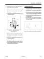
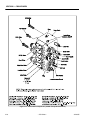
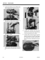
Figure 2-1. Lift Cylinder Assembly
4. Place the cylinder barrel into a suitable holding fixture
5. If applicable, using a suitable spanner wrench,
loosen the spanner nut retainer and remove the
spanner nut from the cylinder barrel.
6. Secure a pull bar to the rod end with a 0.75 - 16 capscrew fastener.
EXTREME CARE SHOULD BE TAKEN WHEN REMOVING THE CYLINDER ROD, HEAD, AND PISTON. AVOID PULLING THE ROD OFFCENTER, WHICH COULD CAUSE DAMAGE TO THE PISTON AND
CYLINDER BARREL SURFACES.
Figure 2-2. Barrel Support
2-6
– JLG Sizzor –
3120855
SECTION 2 - PROCEDURES
face of the rod. In the event that an unacceptable
condition occurs, the rod should be repaired or
replaced.
3. Visually inspect the inside bore of the head for
scratches or polishing. Deep scratches are unacceptable. If polishing occurs the bore should be
checked for ovality.
4. If ovality occurs it is unacceptable. Check the condition of the seals looking particularly for metal particles embedded in the seal surface.
5. Damage to the seal grooves is unacceptable, particularly on the sealing surfaces. In the event that an
unacceptable condition occurs, the piston should be
replaced.
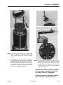
Figure 2-3. Capscrew Removal
7. Using this as a handle, pull out the piston rod and
extend until the piston bottoms out on the head
8. Gently tap the piston against the head to drive the
rod assembly out.
9. Place the rod on a clean surface that will not damage the chrome.
10. Vise - up on the wrench flats on the end of the rod
and remove the piston locknut.
6. Visually inspect the bore on the inside tube assembly for pits and scratches. There should be no
scratches or pits deep enough to catch the fingernail.
7. Inspect threaded portion of barrel for damage. Dress
threads as necessary.
8. Inspect threaded portion of piston for damage.
dress threads as necessary.
9. Inspect seal and o-ring grooves in piston for burrs
and sharp edges. Dress applicable surfaces as necessary.
10. Inspect threaded portion of head for damage. Dress
threads as necessary.
11. Inspect seal and o-ring grooves in head for burrs
and sharp edges. Dress applicable surfaces as necessary.
12. Inspect cylinder head outside diameter for scoring
or other damage and ovality and tapering. Replace
as necessary.
13. Inspect spacer for burrs and sharp edges. If necessary, dress inside diameter surface with Scotch Brite
or equivalent.
Figure 2-4. Rod Support
11. Break the piston free and separate from the rod.
14. If applicable, inspect port block fittings and holding
valve. Replace as necessary.
12. Slide the spacer and head off the rod from the piston
shoulder end.
15. Inspect the oil ports for blockage or the presence of
dirt or other foreign material. Repair as necessary.
Cleaning and Inspection
16. If applicable, inspect piston rings for cracks or other
damage. Replace as necessary.
1. Clean all parts thoroughly in an approved cleaning
solvent.
2. Inspect the cylinder rod for scoring, tapering, ovality,
or other damage. There should be no scratches or
pits deep enough to catch the fingernail. Pits or
scratches that go to the base metal are unacceptable. Chrome should be present over the entire sur-
3120855
Assembly
NOTE: Prior to cylinder assembly, ensure that the proper
cylinder seal kit is used.
– JLG Sizzor –
Apply a light film of hydraulic oil to all components
prior to assembly.
2-7
SECTION 2 - PROCEDURES
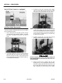
1. Using a special tool, pictured in the following illustration, install a new rod seal into the applicable cylinder head gland groove.
12. Thoroughly rinse the inside of the rod weldment and
allow to drain. Wipe with a lint free rag.
13. Clean and visually inspect all parts for material
defects and contamination.
14. Lubricate the head, piston, and all seals with hydraulic fluid prior to installation.
15. When the rod is ready to be installed in the rod weldment, liberally apply an anti-seize lubricant.
16. Cover the entire rod assembly with hydraulic fluid
and with the rod weldment positioned in a suitable
holding fixture insert the rod into the rod weldment.
17. Using a spanner wrench tighten the cylinder head.
EXTREME CARE SHOULD BE TAKEN WHEN INSTALLING THE
CYLINDER ROD, HEAD, AND PISTON. AVOID PULLING THE ROD
OFF-CENTER, WHICH COULD CAUSE DAMAGE TO THE PISTON
AND CYLINDER BARREL SURFACES.
Figure 2-5. Rod Seal Installation
WHEN INSTALLING NEW "PARKER" TYPE PISTON SEALS,
ENSURE SEALS ARE INSTALLED PROPERLY. IMPROPER SEAL
INSTALLATION COULD RESULT IN CYLINDER LEAKAGE AND
IMPROPER CYLINDER OPERATION.
2. Using a soft mallet, tap a new wiper seal into the
applicable cylinder head gland groove. Install a new
wear ring into the applicable head gland groove.
18. After the cylinder has been reassembled, the rod
should be pushed all the way in (fully retracted) prior
to the reinstallation of any holding valve or valves.
19. If applicable, install the cartridge-type holding valve
and fittings in the port block using new o-rings as
applicable. For proper holding valve torque specifications refer to Table 2-2, Holding Valve Torque
Specifications.
3. Place a new o-ring and back-up seal in the applicable outside diameter groove of the cylinder head.
Table 2-1. Cylinder Component Torque Specifications.
Component
Torque Value (w/Loctite)
4. Install a washer ring onto the rod, then carefully
install the head gland on the rod, ensuring that the
wiper and rod seals are not damaged or dislodged.
Push the head along the rod to the rod end, as
applicable.
Piston Nut - Lift Cylinder - 1932E2
375-450 ft lb
(508-610 Nm)
Piston Nut - Lift Cylinder - 2032E2/
2646E2/3246E2
800-1000 ft lb
(1085-1356 Nm)
5. Carefully slide the piston spacer onto the rod.
6. If applicable, correctly place a new o-ring and backup rings in the inner piston diameter groove.
7. Using suitable protection, clamp the cylinder rod in
a vise or similar holding fixture as close to the piston
as possible.
8. Carefully place the piston on the cylinder rod hand
tight, ensuring that the o-ring and back-up rings are
not damaged or dislodged.
Table 2-2. Holding Valve Torque Specifications.
Description
Torque Value
1932E2, 2032E2 - Hydraforce 1.25" hex 3/4 - 16 thds
20 ft lb (27.1 Nm)
2646E2/3246E2 - Hydraforce - 1"
hex 7/8 - 14 thds
25 ft lb (33.9Nm)
9. Place the piston onto the rod until it abuts the spacer
end and install the seal and guidelock ring.
10. Place the locknut on the end of the cylinder rod and
tighten.
11. Remove the cylinder rod from the holding fixture.
2-8
– JLG Sizzor –
3120855
SECTION 2 - PROCEDURES
2.11 BRAKE CYLINDER REPAIR
DO NOT FULLY EXTEND CYLINDER TO END OF STROKE.
RETRACT CYLINDER SLIGHTLY TO AVOID TRAPPING PRESSURE.
Disassembly
DISASSEMBLY OF THE CYLINDER SHOULD BE PERFORMED ON
A CLEAN WORK SURFACE IN A DIRT FREE WORK AREA.
2. Place the cylinder barrel into a suitable holding fixture.
1. Tag and disconnect the hoses from the cylinder
ports.
3. Using a suitable pair of snap ring pliers, carefully
remove the retaining ring from the cylinder barrel.
4. Attach a suitable pulling device to the cylinder rod
end.
Figure 2-7. Brake Cylinder Assembly
EXTREME CARE SHOULD BE TAKEN WHEN REMOVING THE CYLINDER ROD, GUIDE, AND PISTON. AVOID PULLING THE ROD
OFF-CENTER, WHICH COULD CAUSE DAMAGE TO THE PISTON
AND CYLINDER BARREL SURFACES.
5. With the barrel clamped securely, apply pressure to
the rod pulling device and carefully withdraw the
complete rod assembly from the cylinder barrel.
7. Carefully remove the piston locknut and piston from
the cylinder rod. Remove and discard the piston ring
and o-rings.
8. Carefully remove the guide from the cylinder rod.
Remove and discard the o-ring, back-up ring, rod
seal, and wiper ring.
9. Remove the cylinder rod from the holding fixture.
6. Using suitable protection, clamp the cylinder rod in
a vise or similar holding fixture.
3120855
– JLG Sizzor –
2-9
SECTION 2 - PROCEDURES
Cleaning and Inspection
6. Install the piston locknut on the threaded end of the
cylinder rod and torque to 136-163 Nm.
1. Clean all parts thoroughly in an approved cleaning
solvent.
2. Inspect the cylinder rod for scoring, tapering, ovality,
or other damage. If necessary, dress rod with
Scotch Brite or equivalent. Replace rod if necessary.
3. Inspect threaded portion of rod for excessive damage. Dress threads as necessary.
4. Inspect inner surface of cylinder barrel tube for scoring or other damage. Check inside diameter for
tapering or ovality. Replace if necessary.
5. Inspect piston surface for damage and scoring and
for distortion. Dress piston surface or replace piston
as necessary.
6. Inspect seal and o-ring grooves in piston for burrs
and sharp edges. Dress applicable surfaces as necessary.
7. Inspect cylinder guide inside diameter for scoring or
other damage and for ovality and tapering. Replace
as necessary.
8. Inspect seal and o-ring grooves in guide for burrs
and sharp edges. Dress applicable surfaces as necessary.
9. Inspect cylinder guide outside diameter for scoring
or other damage and ovality and tapering. Replace
as necessary.
10. Inspect the oil ports for blockage or the presence of
dirt or other foreign material. Repair as necessary.
7. Remove the cylinder rod from the holding fixture.
8. Position the cylinder barrel in a suitable holding fixture.
EXTREME CARE SHOULD BE TAKEN WHEN INSTALLING THE
CYLINDER ROD, GUIDE, AND PISTON. AVOID PULLING THE ROD
OFF-CENTER, WHICH COULD CAUSE DAMAGE TO THE PISTON
AND CYLINDER BARREL SURFACES.
9. With the barrel clamped securely, and while adequately supporting the cylinder rod, insert the piston
end of the rod into the cylinder barrel. Ensure that
the piston ring and o-ring are not damaged or dislodged.
10. Continue pushing the rod into the barrel until the cylinder guide can be inserted into the cylinder barrel.
11. Using all applicable safety precautions, secure the
cylinder rod assembly with a new retaining ring.
12. Reconnect the hydraulic hoses to the applicable cylinder ports.
2.12 STEER CYLINDER REPAIR
Disassembly
Assembly
NOTE: Prior to cylinder assembly, ensure that the proper
cylinder seal kit is used.
DISASSEMBLY OF THE CYLINDER SHOULD BE PERFORMED ON
A CLEAN WORK SURFACE IN A DIRT FREE WORK AREA.TAG
AND DISCONNECT THE HOSES FROM THE CYLINDER PORTS.
Apply a light film of hydraulic oil to all components
prior to assembly.
1. Using suitable protection, clamp the cylinder rod in
a vise or similar holding fixture.
2. Place a new wiper ring, rod seal, o-ring, and back-up
ring into the applicable cylinder guide grooves.
3. Carefully install the guide on the rod, ensuring that
the wiper ring and rod seal are not damaged or dislodged. Push the guide onto the rod.
4. Place a new piston ring and o-rings on the piston.
5. Carefully place the piston on the threaded end of the
cylinder rod, ensuring that the o-ring is not damaged
or dislodged. Push the piston onto the rod as far as
it will go.
2-10
DO NOT FULLY EXTEND CYLINDER TO END OF STROKE.
RETRACT CYLINDER SLIGHTLY TO AVOID TRAPPING PRESSURE.
1. Place the cylinder barrel into a suitable holding fixture.
2. Using a suitable hammer, tap around the outside of
the cylinder barrel and guide to shatter the Loctite.
3. Using a suitable spanner wrench, carefully remove
the guide from the rod clevis end of the cylinder barrel.
4. Attach a suitable pulling device to the clevis end of
cylinder rod section one.
– JLG Sizzor –
3120855
SECTION 2 - PROCEDURES
EXTREME CARE SHOULD BE TAKEN WHEN REMOVING THE CYLINDER ROD, GUIDE, AND PISTON. AVOID PULLING THE ROD
OFF-CENTER, WHICH COULD CAUSE DAMAGE TO THE PISTON
AND CYLINDER BARREL SURFACES.
5. With the barrel clamped securely, apply pressure to
the rod pulling device and carefully withdraw the
complete rod assembly from the cylinder barrel.
6. Using a suitable hammer, tap around the outside of
the cylinder barrel and guide to shatter the Loctite.
7. Using a suitable spanner wrench, carefully remove
the remaining guide from the cylinder barrel.
Remove and discard the wiper ring, rod seal, backup ring and o-ring.
8. Using suitable protection, clamp cylinder rod section two in a vise or similar holding fixture.
9. Carefully remove cylinder rod section one from cylinder rod section two and carefully remove the piston from the cylinder rod. Remove and discard the
piston seal and o-ring.
Figure 2-8. Steer Cylinder Assembly
10. Carefully remove the guide from cylinder rod section
one. Remove and discard the o-ring, back-up ring,
rod seal, and wiper ring.
11. Remove the cylinder rod from the holding fixture.
Cleaning and Inspection
1. Clean all parts thoroughly in an approved cleaning
solvent.
2. Inspect the cylinder rod for scoring, tapering, ovality,
or other damage. If necessary, dress rod with
Scotch Brite or equivalent. Replace rod if necessary.
3. Inspect threaded portion of rod for excessive damage. Dress threads as necessary.
3120855
4. Inspect inner surface of cylinder barrel tube for scoring or other damage. Check inside diameter for
tapering or ovality. Replace if necessary.
5. Inspect piston surface for damage and scoring and
for distortion. Dress piston surface or replace piston
as necessary.
6. Inspect seal and o-ring grooves in piston for burrs
and sharp edges. Dress applicable surfaces as necessary.
7. Inspect cylinder guide inside diameter for scoring or
other damage and for ovality and tapering. Replace
as necessary.
– JLG Sizzor –
2-11
SECTION 2 - PROCEDURES
8. Inspect seal and o-ring grooves in guide for burrs
and sharp edges. Dress applicable surfaces as necessary.
10. Continue pushing the rod into the barrel until the cylinder rod guide can be inserted into the end of the
cylinder barrel.
9. Inspect cylinder guide outside diameter for scoring
or other damage and ovality and tapering. Replace
as necessary.
11. Coat the threads of the cylinder rod guide with Loctite #271 then secure the cylinder rod guide to the
cylinder barrel using a suitable spanner wrench.
10. Inspect the oil ports for blockage or the presence of
dirt or other foreign material. Repair as necessary.
12. On the remaining cylinder rod guide, place a new
wiper ring, rod seal, o-ring, and back-up ring into the
cylinder rod guide grooves.
Assembly
13. Carefully install the cylinder rod guide onto rod section two and slide the guide into the end of the cylinder barrel.
NOTE: Prior to cylinder assembly, ensure that the proper
cylinder seal kit is used. Refer to the Illustrated Parts
Manual.
Apply a light film of hydraulic oil to all components
prior to assembly.
1. Using suitable protection, clamp the cylinder rod
section one in a vise or similar holding fixture.
2. Place a new wiper ring, rod seal, o-ring, and back-up
ring into the cylinder rod guide grooves.
3. Carefully install the cylinder rod guide on rod section
one, ensuring that the wiper ring and rod seal are
not damaged or dislodged. Push the guide onto the
rod section.
4. Place a new piston ring on the piston and a new oring on the threaded end of cylinder rod section two.
5. Carefully place the piston on the threaded end of
cylinder rod section two, ensuring that the o-ring is
not damaged or dislodged. Push the piston onto the
rod as far as it will go.
6. Attach cylinder rod section one to the threaded end
of cylinder rod section two and assemble.
7. Remove the cylinder rod assembly from the holding
fixture.
8. Position the cylinder barrel in a suitable holding fixture.
14. Coat the threads of the cylinder rod guide with Loctite #271 then secure the cylinder rod guide to the
cylinder barrel using a suitable spanner wrench.
15. Reconnect the hydraulic hoses to the applicable cylinder ports.
2.13 TILT SWITCH ADJUSTMENT
NOTE: The machine may be equipped with a tilt switch (sensor), factory set to activate when the machine is elevated and out of level in any direction at 1.5° on the
1932E2/2032E2 and 2° on the 2632E2/2646E2/
3246E2. When this occurs the drive function is cut
out. Consult factory for tilt sensor adjustment. The
only field adjustment necessary is leveling the switch
on the spring loaded studs. There are two methods
of adjustment, a manual adjustment and an adjustment using a voltmeter.
PERFORM TILT ALARM SWITCH LEVELING PROCEDURE A MINIMUM OF EVERY SIX MONTHS TO ENSURE PROPER OPERATION
AND ADJUSTMENT OF SWITCH.
Manual Adjustment
1. Park the machine on a flat, level surface and ensure
the machine is level.
NOTE: Ensure switch mounting bracket is level and securely
attached.
EXTREME CARE SHOULD BE TAKEN WHEN INSTALLING THE
CYLINDER ROD, CYLINDER ROD GUIDE, AND PISTON. AVOID
PULLING THE ROD OFF-CENTER, WHICH COULD CAUSE DAMAGE TO THE PISTON AND CYLINDER BARREL SURFACES.
9. With the barrel clamped securely, and while adequately supporting the cylinder rod assembly, insert
the piston end of the rod assembly into the cylinder
barrel. Ensure that the piston ring and o-ring are not
damaged or dislodged.
2-12
2. Level the base of the indicator by tightening the
three flange nuts. Tighten each nut through approximately one half of its spring travel. DO NOT ADJUST
THE (X) NUT DURING THE REMAINDER OF THE
PROCEDURE.
3. With the electrical connections complete, slowly
tighten one of the (Y) nuts until the circuit is closed
(the light on the Platform Control Console illuminates, the tilt alarm sounds).
– JLG Sizzor –
3120855
SECTION 2 - PROCEDURES
4. Slowly back off the nut, counting the number of
turns, until the circuit is closed again
5. Divide the number of turns determined in step 4in
half. Tighten the nut this many turns. The line determined by this nut and the (X) nut is now parallel to
the ground.
6. Repeat steps 3 through 5 for the remaining (Y) nut.
The switch is now level.
Voltmeter Adjustment
1. Park the machine on a flat, level surface and ensure
the machine is level.
2. If the motor is not running, turn the ignition switch to
ON.
3. Connect the black lead of the voltmeter to ground
and the red lead to the yellow wire protruding from
the pot on the bottom of the sensor.
4. Adjust the leveling nuts to obtain the highest possible voltage reading.
5. Check the voltage at the trip point in all four directions. If the voltage reading is not symmetrical,
repeat step 4 above.
Figure 2-9. Tilt Switch Leveling
Manual Adjustment
Figure 2-10. Tilt Switch Leveling Voltmeter Adjustment
7. Divide the number of turns determined in step 4 in
half. Tighten the nut this many turns. The line determined by this nut and the (X) nut is now parallel to
the ground.
8. Repeat steps 3 through 5 for the remaining (Y) nut.
The switch is now level.
9. Individually push down on one corner at a time;
there should be enough travel to cause the switch to
trip. If the switch does not trip in all three tests, the
flange nuts have been tightened too far. Loosen the
(X) nut and repeat steps 3 through 7.
3120855
– JLG Sizzor –
2-13
SECTION 2 - PROCEDURES
Figure 2-11. Control Valve Components
2.14 PRESSURE SETTING PROCEDURES
NOTE: Make all pressure adjustments with motor operating
and hydraulic oil at normal operating temperature. In
addition, all functions must be operated from the
platform control station in order to achieve full pump
speed. It may be necessary to use an assistant to
adjust the pressure settings while operating the functions from the platform control station.
Lift Relief for Non Proportional Control
Machines
3. From the platform control station, activate the Lift Up
function by pressing the LIFT switch and activating
the controller to the full forward position.
4. Adjust Lift Relief to value in the Pressure Settings
Chart.
5. Shut down hydraulic system and remove pressure
gauge.
Steer Adjustment for Non Proportional
Control Machines
1. With pressure gauge at "MP" port on control valve
activate steer in either direction.
1. Install a pressure gauge at gauge port MP, located at
the inside top of the valve body. The port is identified
by a stamping on the valve body.
2. Adjust Steer Relief to value in the Pressure Settings
Chart
2. Disconnect the hose from valve port 3, then plug the
hose and the valve port.
2-14
– JLG Sizzor –
3120855
SECTION 2 - PROCEDURES
Main Relief Pressure Switch for Non
Proportional Control Machines
Steer Adjustment for Proportional Control
Machines
1. With pressure gauge at "MP" port on control valve
activate steer in either direction.
1. Install a pressure gauge at gauge port MP, located at
the bottom front of the valve body. The port is identified by a stamping on the valve body.
2. Activate drive by pressing the drive switch and activating the controller to the full forward position.
While holding the controller, activate steer right and
check steer right pressure. If necessary, adjust steer
right pressure to value in the Pressure Settings
Chart.
2. Disconnect the power from the drive valve on top of
the valve body.
3. Activate drive by moving the joystick to the full forward position.
3. Activate drive by pressing the drive switch and activating the controller to the full forward position.
While holding the controller, activate steer left and
check steer left pressure. If necessary, adjust steer
left pressure to value in the Pressure Settings Chart.
4. Adjust Main Relief to value in the pressure setting
chart.
5. Reinstall the electrical connections to the drive
valve.
Main Relief and High Drive Pressure Switch
for Proportional Control Machines
Lift Relief Adjustments for Proportional
Control Machines
1. Install a pressure gauge at gauge port MP, located at
the bottom front of the valve body. The port is identified by a stamping on the valve body.
1. Install a pressure gauge at gauge port MP, located at
the inside top of the valve body. The port is identified
by a stamping on the valve body.
2. Close the steer valve completely by turning clockwise.
2. Disconnect the hose from valve port 3, then plug the
hose and the valve port.
3. Once the steer valve is closed activate the steer
switch in either direction until the steer cylinder bottoms out.
3. From the platform control station, activate the Lift Up
function by pressing the LIFT switch and activating
the controller to the full forward position.
4. Adjust your Main Pressure to value in the Pressure
Settings Chart.
4. Adjust Lift Relief to value in the Pressure Settings
Chart.
5. Once you have adjusted your main pressure be sure
and reset your steer pressure back to value in the
Pressure Settings Chart.
5. Shut down hydraulic system and remove pressure
gauge.
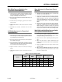
Table 2-3. Pressure Settings Chart
1932E2
2032E2
Function
3120855
2632E2/2646E2/
3246E2
3246E2 w/Proportional
Control
psi
bar
psi
bar
psi
bar
psi
bar
Main Relief/High Drive
3200
221
3200
221
3200
221
3000
207
Lift
2300
159
2200
152
2400
165
2100
145
Steer
2000
138
2000
138
2000
138
2100
145
– JLG Sizzor –
2-15
SECTION 2 - PROCEDURES
Figure 2-12. Control Valve Components (3246E2 w/Proportional Control)
2-16
– JLG Sizzor –
3120855
SECTION 2 - PROCEDURES
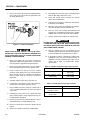
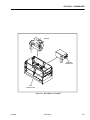
WELDER
TERMINAL
CONNECTOR
FIRE
EXTINGUISHER
Figure 2-13. Quick Welder™ Installation
3120855
– JLG Sizzor –
2-17
SECTION 2 - PROCEDURES
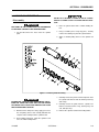
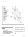
Figure 2-14. Drive Motor (Sauer Danfoss)
4. With the housing in the holding device, press the
shaft out of the housing. Collect the needle bearings
for possible re-use.
2.15 DRIVE MOTOR (SAUER DANFOSS)
Dismantling
1. Place motor in proper holding device that allows
access to the output shaft.
2. Carefully remove end cover sideways being sure to
catch any parts that may fall from the gearwheel.
3. The needles bearings will fall out during dismantling
and can be collected and reused. The outer ring and
thrust bearing need not be removed.
2-18
5. Remove the housing from the holding device and
place on a workbench. With a screwdriver, gently
lever the dust seal ring from the housing.
6. Extract the shaft seal from the housing.
7. Press the remaining parts out using hydraulic equipment.
8. Clean all parts carefully with a low aromatic kerosene.
– JLG Sizzor –
3120855
SECTION 2 - PROCEDURES
Assembly
and the gearwheel engage (15°). Turn the gearwheel
to line up the screw holes.
NOTE: Before assembly, inspect all parts and replace if necessary.
Before assembly, lubricate all parts with hydraulic oil
and grease rubber parts with Vaseline.
13. Rotate the end cover to line up the screw holes.
14. Use new washers and a 13 mm socket spanner.
Torque to 330-380 lb in (3.75 - 4.25 daNm).
15. Screw in plastic plugs.
1. Turn motor housing so the rear end faces upwards.
Press shaft seal into housing.
16. Turn the motor over and strike the dust seal into
place with a plastic hammer and suitable mandrel.
2. The bearing race can be fitted in any position.
17. Secure the key in place with tape.
3. Place the needle bearings in the outer ring and hold
them in place with grease. Place the whole bearing
into the housing. Press the bearing into position
using pressure equipment if necessary.
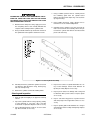
2.16 DRIVE MOTOR (REXROTH)
Disassembly
4. Carefully insert shaft through bearing housing.
5. Place O-ring (greased) in bearing housing O-ring
recess.
6. Place spring washer on balance plate, insert O-ring
in recess and lubricate with grease. Place balance
plate lightly in position so that it engages. Be careful
not to damage the O-ring.
1. Place the drive motor vertically in a vice with the output shaft pointing downwards.
2. Using a 17mm spanner wrench loosen the 7 cover
bolts. remove the cover with the bolts.
3. Lift off the displacer and the intermediate disk.
4. Remove the cardan shaft.
7. Place the disc valve on the shaft with channels
upwards so that the long tab on the disc valve
engages with the slot in the shaft.
5. Remove the control sleeve.
8. If there is a difference in the spline length, fit the cardan shaft with he long spline end in the output shaft.
Mark the bottom of the cardan spline that lies adjacent to the long tab on the disc valve.
7. Turn the drive around in the vise so that the output
shaft is facing up. Remove the keyed shaft.
9. Place the needles in the outer ring and hold them in
place with grease. Carefully place the distributor
plate on the bearing housing so that the shaft enters
the bearing. Press the distributor plate until it stops
on the housing and line up the screw holes.
10. Place the O-rings (greased) in the gearwheel O-ring
recesses. If there is a recess on one end of the
splined hole, position the gearwheel with recess on
the same side as the smallest screw hole (stage
hole) in the gearwheel rim. Fit the gearwheel set with
this side facing the motor.
11. Clockwise Revolution:
Fit the gearwheel set on the cardan shaft so that the
top of a tooth in the external teeth of the gearwheel
is vertically over the mark on the cardan shaft. Turn
the gearwheel set counterclockwise until the cardan
shaft and gearwheel engage (15°). Turn the gearwheel rim to line up the screw holes.
12. Counterclockwise Revolution:
Fit the gearwheel set on the cardan shaft so that the
top of a tooth in the external teeth of the gearwheel
is vertically over the mark on the cardan shaft. Turn
the gearwheel set clockwise until the cardan shaft
3120855
6. Remove the check valves consisting of ball, limit,
stop and filler (filler only when one valve is installed).
8. Loosen the 8 socket head cap screws on the flange
mounting using a 4mm allan wrench.
9. Withdraw the flange from the shaft while holding the
flange in a special fixture.
10. Turn the motor around again. Attach a mandrel and
press the output shaft with bearing out of the motor
housing with the help of a lever press.
Assembly
1. The output shaft with pressed on and adjusted
tapered roller bearing and cylindrical shaft is to be
centrically positioned onto the housing edge. Press
the complete assembly into the housing to the limit
stop with the help of the press.
NOTE: Do not jam.
2. Before mounting the flange, put a mounting sleeve
onto the shaft.
NOTE: Be sure that the seal is thoroughly oiled.
3. Position the flange with slight pressure into the
housing. Take care to avoid damage to the seals.
– JLG Sizzor –
2-19
SECTION 2 - PROCEDURES
4. Screw in the 8 socket head cap screws. Using a
Torque wrench, tighten to 80 in lb (8 Nm).
5. After turning the motor around introduce the control
sleeve. Make sure that the cylindrical roll of the output shaft clicks into the groove of the control sleeve.
6. Insert the O-ring into the housing.
7. Installation of the check valves:
Insert 2 ball valves and carefully drive them in using
a mandrel.
8. Insert the limit stop and put the filler into position for
the lower valve.
IFTHETORQLINK™ IS NOT FIRMLY HELD IN THE VISE, IT COULD
BE DISLODGED DURINGTHE SERVICE PROCEDURES, CAUSING
INJURY.
2. Scribe an alignment mark down and across the
Torqlink™ components from end cover (2) to housing (18) to facilitate reassembly orientation where
required. Loosen two shuttle or relief valve plugs
(21) for disassembly later if included in end cover. 3/
16 or 3/8 inch Allen wrench or 1 inch hex socket
required.
9. Put the cardan shaft into position. Note that the
marked tooth must comply with the marking on the
control sleeve.
10. Position the intermediate disk.
11. Insert the O-ring into the recess of the displacer.
12. Place the displacer so that the tooth marking on the
cardan shaft on the displacer side meshes with the
tooth base of the rotor gearwheel that is located
centrally at the lowest point in the outer profile of the
rotor gearwheel. This is only possible at 6 positions.
13. Insert O-ring.
14. Insert spacer.
15. Remount cover, tighten the 7 hexagon bolts using a
torque wrench (torque to 60Nm 43 ft lb). The output
shaft should turn easily.
2.17 DRIVE MOTOR (PARKER)
Disassembly and inspection
1. Place the Torqlink™ in a soft jawed vice, with coupling shaft (12) pointed down and the vise jaws
clamping firmly on the sides of the housing (18)
mounting flange or port bosses. Remove manifold
port O-Rings (18A) if applicable.
2-20
3. Remove the five, six, or seven special ring head
bolts (1) using an appropriate 1/2 or 9/16 inch size
socket. Inspect bolts for damaged threads, or sealing rings, under the bolt head. Replace damaged
bolts
– JLG Sizzor –
3120855
SECTION 2 - PROCEDURES
.
.
4. Remove end cover assembly (2) and seal ring (4).
Discard seal ring
3120855
NOTE: Refer to the appropriate “alternate cover construction” on the exploded view to determine the end
cover construction being serviced.
– JLG Sizzor –
2-21
SECTION 2 - PROCEDURES
1. Special Bolts
2. End Cover
3. Seal Ring-Commutator
4. Seal Ring
5. Commutator Ring
6. Commutator Ring
7. Manifold
8. Rotor Set
8A.Rotor
8B. Stator or Stator Vane
8C. Vane
8D. Stator Half
9. Wear Plate
10. Drive Link
12. Coupling Shaft
13. Bearing/Bushing, Inner
14. Thrust Washer
15. Thrust Bearing
16. Seal
17. Back-up Washer
18. Housing
18A. O-Ring
19. Bearing/Bushing, Outer
20. Dirt & Water Seal
21. Plug
Figure 2-15. Parker Drive Motor
5.
If the end cover (2) is equipped with shuttle valve
components, remove the two previously loosened
plugs (21).
BE READY TO CATCH THE SHUTTLE VALVE OR RELIEF VALVE
COMPONENTS THAT WILL FALL OUT OF THE END COVER
VALVE CAVITY WHEN THE PLUGS ARE REMOVED.
NOTE: The insert and if included the orifice plug in the end
cover (2) must not be removed as they are serviced
as an integral part of the end cover.
2-22
– JLG Sizzor –
3120855
SECTION 2 - PROCEDURES
6. Thoroughly wash end cover (2) in proper solvent
and blow dry. Be sure the end cover valve apertures,
including the internal orifice plug, are free of contamination. Inspect end cover for cracks and the bolt
head recesses for good bolt head sealing surfaces.
Replace end cover as necessary.
these conditions exist, replace commutator and
commutator ring as a matched set.
NOTE: A polished pattern (not scratches) on the cover from
rotation of the commutator (5) is normal. Discoloration would indicate excess fluid temperature, thermal
shock, or excess speed and require system investigation for cause and close inspection of end cover,
commutator, manifold, and rotor set.
7. Remove commutator ring (6). Inspect commutator
ring for cracks, or burrs.
9. Remove manifold (7) and inspect for cracks surface
scoring, brinelling or spalling. Replace manifold if
any of these conditions exist. A polished pattern on
the ground surface from commutator or rotor rotation is normal. Remove and discard the seal rings (4)
that are on both sides of the manifold.
8. Remove commutator (5) and seal ring (3) Remove
seal ring from commutator, using an air hose to blow
air into ring groove until seal ring is lifted out and discard seal ring. Inspect commutator for cracks or
burrs, wear, scoring, spalling or brinelling. If any of
NOTE: The manifold is constructed of plates bonded
together to form an integral component not subject
tofurtherdisassemblyforservice.Compare configuration of both sides oft hem an if old to ensure that
same surface is reassembled against the rotor set.
3120855
– JLG Sizzor –
2-23
SECTION 2 - PROCEDURES
10. Remove rotor set (8) and warplane (9), together to
retain the rotor set in its assembled form, maintaining the same rotor vane (8C) to stator (8B) contact
surfaces. The drive link (10) may come away from
the coupling shaft (12) with the rotor set, and wearplate.You may have to shift the rotor set on the warplane to work the drive link out of the rotor (8A) and
warplane. Inspect the rotor set in its assembled form
for nicks, scoring, or spalling on any surface and for
broken or worn splines. If the rotor set component
requires replacement, the complete rotor set must
be replaced as it is a matched set. Inspect the warplane for cracks, brinelling, or scoring. Discard seal
ring (4) that is between the rotor set and wearplate.
NOTE: The rotor set (8) components may become disassembled during service procedures. Marking the surface of the rotor and stator that is facing UP, with
etching ink or grease pencil before removal from
Torqlink™ will ensure correct reassembly of rotor
into stator and rotor set intoTorqlink™.Marking all
rotor components and mating spline components for
exact repositioning at assembly will ensure maximum wear life and performance of rotor set andTorqlink™.
2-24
NOTE: Series TG Torqlinks™ may have a rotor set with two
stator halves (8B) with a seal ring (4) between them
and two sets of seven vanes (8C). Discard seal ring
only if stator halves become disassembled during
the service procedures.
NOTE: A polished pattern on the wear plate from rotor rotation is normal.
11. Place rotor set (8) and wear plate (9) on a flat sur-
face and center rotor (8A) in stator (8B) such
that two rotor lobes (180 degrees apart) and a
roller vane (8C) centerline are on the same stator centerline. Check the rotor lobe to roller
vane clearance with a feeler gage at this common centerline. If there is more than 0.005
inches (0.13 mm) of clearance, replace rotor
set.
NOTE: If rotor set (8) has two stator halves (8B & 8D) and
two sets of seven vanes (8C & 8E) as shown in the
alternate construction TG rotor set assembly view,
check the rotor lobe to roller vane clearance at both
ends of rotor.
12. Remove drive link (10) from coupling shaft (12) if it
was not removed with rotor set and wear plate.
Inspect drive link for cracks and worn or damaged
splines. No perceptible lash (play) should be noted
between mating spline parts. Remove and discard
seal ring (4) from housing (18).
– JLG Sizzor –
3120855
SECTION 2 - PROCEDURES
13. Remove thrust bearing (11) from top of coupling
shaft (12). Inspect for wear, brinelling, corrosion and
a full complement of retained rollers.
14. Check exposed portion of coupling shaft (12) to be
sure you have removed all signs of rust and corrosion which might prevent its withdrawal through the
seal and bearing. Crocus cloth or fine emery paper
may be used
.
NOTE: Minor shaft wear in seal area is permissible. If wear
exceeds 0.020 inches (0.51 mm) diametrically,
replace coupling shaft.
NOTE: A slight “polish” is permissible in the shaft bearing
areas. Anything more would require coupling shaft
replacement.
16. 16. Remove and discard seal ring (4) from housing
(18).
17. Remove thrust bearing (15) and thrust washer (14)
Inspect for wear, brinelling, corrosion and a full complement of retained rollers.
15. Remove coupling shaft (12), by pushing on the output end of shaft. Inspect coupling shaft bearing and
seal surfaces for spalling, nicks, grooves, severe
wear or corrosion and discoloration. Inspect for
damaged or worn internal and external splines or
keyway. Replace coupling shaft if any of these conditions exist.
3120855
18.
Remove seal (16) and back up washer (17) from
Small Frame, housing (18). Discard both.
– JLG Sizzor –
2-25
SECTION 2 - PROCEDURES
21. If the housing (18) assembly has passed inspection
to this point, inspect the housing bearings/bushings
(19) and (13) and if they are captured in the housing
cavity the two thrust washers (14) and thrust bearing
(15). The bearing rollers must be firmly retained in
the bearing cages, but must rotate and orbit freely.
All rollers and thrust washers must be free of brinelling and corrosion. The bushing (19) or (13) to coupling shaft diameter clearance must not exceed
0.010 inch (0.025 mm). A bearing, bushing, or thrust
washer that does not pass inspection must be
replaced. If the housing has passed this inspection
the disassembly of the Torqlink™ is completed.
19. Remove housing (18) from vise, invert it and remove
and discard seal (20). A blind hole bearing or seal
puller is required.
20. Inspect housing (18) assembly for cracks, the
machined surfaces for nicks, burrs, brinelling or corrosion. Remove burrs that can be removed without
changing dimensional characteristics. Inspect
tapped holes for thread damage. If the housing is
defective in these areas, discard the housing assembly.
2-26
– JLG Sizzor –
3120855
SECTION 2 - PROCEDURES
NOTE: The depth or location of bearing/bushing (13) in relation to the housing wear plate surface and the depth
or location of bearing/bushing (19) in relation to the
beginning of bearing/bushing counter bore should be
measured and noted before removing the bearings/
bushings. This will facilitate the correct reassembly
of new bearings/bushings.
Assembly
Replace all seals and seal rings with new ones each time
you reassemble the Torqlink™ unit. Lubricate all seals and
seal rings with SAE 10W40 oil or clean grease before
assembly.
NOTE: Individual seals and seal rings as well as a complete
seal kit are available. The parts should be available
through most OEM parts distributors or Parker
approved Torqlink™ distributors. (Contact your local
dealer for availability).
NOTE: Unless otherwise indicated, do not oil or grease
parts before assembly.
Wash all parts in clean petroleum-based solvents before
assembly. Blow them dry with compressed air. Remove
any paint chips from mating surfaces of the end cover,
commutator set, manifold rotor set, wear plate and housing and from port and sealing areas.
22. If the bearings, bushing or thrust washers must be
replaced use a suitable size bearing puller to
remove bearing/bushings (19) and (13) from housing (18) without damaging the housing. Remove
thrust washers (14) and thrust bearing (15) if they
were previously retained in the housing by bearing
(13).
SINCE THEY ARE FLAMMABLE, BE EXTREMELY CAREFUL WHEN
USING ANY SOLVENT. EVEN A SMALL EXPLOSION OR FIRE
COULD CAUSE INJURY OR DEATH.
WEAR EYE PROTECTION AND BE SURE TO COMPLY WITH OSHA
OR OTHER MAXIMUM AIR PRESSURE REQUIREMENTS.
1. If the housing (18) bearing components were
removed for replacement, thoroughly coat and pack
a new outer bearing/bushing (19) with clean corrosion resistant grease recommended in the material
section. Press the new bearing/bushing into the
counterbore at the mounting flange end of the housing, using the appropriate sized bearing mandrel,
which will control the bearing/ bushing depth.
Torqlink™ housings require the use of bearing mandrel to press bearing/ bushing (19) into the housing
to a required depth of 0.151/0.161 inches (3.84/4.09
mm) from the end of the bearing counterbore.
3120855
– JLG Sizzor –
2-27
SECTION 2 - PROCEDURES
NOTE: Bearing mandrel must be pressed against the lettered end of bearing shell. Take care that the housing bore is square with the press base and the
bearing/bushing is not cocked when pressing a bearing/bushing into the housing.
IF THE BEARING MANDREL SPECIFIED IN THE “TOOLS AND
MATERIALS REQUIRED FOR SERVICING” SECTION IS NOT
AVAILABLE AND ALTERNATE METHODS ARE USED TO PRESS
IN BEARING/BUSHING (13) AND (19) THE BEARING/BUSHING
DEPTHS SPECIFIED MUST BE ACHIEVED TO INSURE ADEQUATE
BEARING SUPPORT AND CORRECT RELATIONSHIP TO ADJACENT COMPONENTS WHEN ASSEMBLED.
BECAUSE THE BEARING/BUSHINGS (13) AND (19) HAVE A
PRESS FIT INTO THE HOUSING THEY MUST BE DISCARDED
WHEN REMOVED. THEY MUST NOT BE REUSED.
2. The Torqlink™ inner housing bearing/bushing (13)
can now be pressed into its counterbore in housing
(18) flush to 0.03 inch (.76 mm) below the housing
wear plate contact face. Use the opposite end of the
bearing mandrel that was used to press in the outer
bearing/bushing (19).
2-28
3. Press a new dirt and water seal (20) into the housing
(18) outer bearing counterbore.
– JLG Sizzor –
3120855
SECTION 2 - PROCEDURES
The Torqlink™ dirt and water seal (20) must be pressed in
until its’ flange is flush against the housing.
4. Place housing (18) assembly into a soft jawed vise
with the coupling shaft bore down, clamping against
the mounting flange.
ORIGINAL DESIGN LARGE FRAME, TF & TG TORQLINKS™ THAT
DO NOT HAVE BACKUP WASHER (25) WHEN DISASSEMBLED
MUST BE ASSEMBLED WITH A NEW BACKUP WASHER (17), NEW
BACKUP WASHER (25), AND NEW SEAL (16).
6. Assemble thrust washer (14) then thrust bearing (15)
that was removed from the Torqlink™.
5. On the Torqlinks™ assemble a new backup washer
(17) and new seal (16) with the seal lip facing toward
the inside of Torqlink™, into their respective counterbores in housing (18) if they were not assembled in
procedure 2.
3120855
NOTE: Torqlinks™ require one thrust washer (14) with
thrust bearing (15).The coupling shaft will be seated
directly against the thrust
– JLG Sizzor –
2-29
SECTION 2 - PROCEDURES
7. Apply masking tape around splines or keyway on
shaft (12) to prevent damage to seal.
.
8. Be sure that a generous amount of clean corrosion
resistant grease has been applied to the lower
(outer) housing bearing/bushing (19). Install the
coupling shaft (12) into housing (18), seating it
against the thrust bearing (15) in the housings.
9. Apply a small amount of clean grease to a new seal
ring (4) and insert it into the housing (18) seal ring
groove.
THE OUTER BEARING (19) IS NOT LUBRICATED BY THE SYSTEM’S HYDRAULIC FLUID. BE SURE IT IS THOROUGHLY
PACKED WITH THE RECOMMENDED GREASE, PARKER GEAR
GREASE SPECIFICATION #045236, E/M LUBRICANT #K-70M.
NOTE: Mobil Mobilith SHC ® 460
NOTE: A 102Tube (P/N 406010) is included in each seal kit.
NOTE: The coupling shaft (12) will be flush or just below the
housing wear plate surface on Torqlinks™ when
properly seated. The coupling shaft must rotate
smoothly on the thrust bearing package
2-30
NOTE: One or two alignment studs screwed finger tight into
housing (18) bolt holes, approximately 180 degrees
apart, will facilitate the assembly and alignment of
components as required in the following procedures.The studs can be made by cutting off the
heads of either 3/8-24 UNF 2A or 5/16-24 UNF 2A
bolts as required that are over 0.5 inch (12.7 mm)
longer than the bolts (1) used in the Torqlink™.
– JLG Sizzor –
3120855
SECTION 2 - PROCEDURES
10. Install drive link (10) the long splined end down into
the coupling shaft (12) and engage the drive link
splines into mesh with the coupling shaft splines.
NOTE: Use any alignment marks put on the coupling shaft
and drive link before disassembly to assemble the
drive link splines in their original position in the mating coupling shaft splines.
11. Assemble wear plate (9) over the drive link (10) and
alignment studs onto the housing (18).
.
NOTE: It may be necessary to turn one alignment stud out
of the housing (18) temporarily to assemble rotor set
(8) or manifold (7) over the drive link.
NOTE: If necessary, go to the appropriate, “Rotor Set Component Assembly Procedure.”
NOTE: The rotor set rotor counterbore side must be down
against wear plate for drive link clearance and to
maintain the original rotor-drive link spline contact. A
rotor set without a counterbore and that was not
etched before disassembly can be reinstalled using
the drive link spline pattern on the rotor splines if
apparent, to determine which side was down.The
rotor set seal ring groove faces toward the wear
plate (9).
14. Apply clean grease to a new seal ring (4) and
assemble it in the seal ring groove in the rotor set
contact side of manifold (7).
12. Apply a small amount of clean grease to a new seal
ring (4) and assemble it into the seal ring groove on
the wear plate side of the rotor set stator (8B).
13. Install the assembled rotor set (8) onto wear plate
(9) with rotor (8A) counterbore and seal ring side
down and the splines into mesh with the drive link
splines
3120855
NOTE: The manifold (7) is made up of several plates
bonded together permanently to form an integral
component.The manifold surface that must contact
the rotor set has it’s series of irregular shaped cavities on the largest circumference or circle around the
inside diameter.The polished impression left on the
manifold by the rotor set is another indication of
which surface must contact the rotor set.
– JLG Sizzor –
2-31
SECTION 2 - PROCEDURES
15. Assemble the manifold (7) over the alignment studs
and drive link (10) and onto the rotor set. Be sure the
correct manifold surface is against the rotor set.
16. Apply grease to a new seal ring (4) and insert it in
the seal ring groove exposed on the manifold.
17. Assemble the commutator ring (6) over alignment
studs onto the manifold.
19. If shuttle valve components items #21, were
removed from the end cover (2) turn a plug (21),
loosely into one end of the valve cavity in the end
cover. A 3/16 inch Allen wrench is required.
20. Assemble a new seal ring (4) into end cover (2) and
assemble end cover over the alignment studs and
onto the commutator set. If the end cover has only 5
bolt holes be sure the cover holes are aligned with
the 5 threaded holes in housing (18).The correct 5
bolt end cover bolt hole relationship to housing port
bosses.
18. Assemble a new seal ring (3) flat side up, into commutator (5) and assemble commutator over the end
of drive link (10) onto manifold (7) with seal ring side
up.
2-32
– JLG Sizzor –
3120855
SECTION 2 - PROCEDURES
.
NOTE: If the end cover has a valve (24) or has five bolt
holes, use the line you previously scribed on the
cover to radially align the end cover into its original
position.
21. Assemble the 5 or 7 special bolts (1) and screw in
finger tight. Remove and replace the two alignment
studs with bolts after the other bolts are in place.
Alternately and progressively tighten the bolts to pull
the end cover and other components into place with
a final torque of 22-26 ft. lbs. 45-55 ft. lbs.(61-75 N
m) for the seven 3/8-24 threaded bolts
NOTE: The special bolts required for use with the relief or
shuttle valve (24) end cover assembly (2) are longer
than the bolts required with standard and cover
assembly. Refer to the individual service parts lists
or parts list charts for correct service part number if
replacement is required.
Torque the two shuttle valve plug assemblies
(21) in end cover assembly to 9-12 ft. lbs.
(12-16 N m) if cover is so equipped.
Torque the two relief valve plug assemblies
(21) in end cover assembly to 45-55 ft.
3120855
– JLG Sizzor –
2-33
SECTION 2 - PROCEDURES
lbs.(61-75 N m) if cover is so equipped.
3. Assemble the rotor (8A), counterbore down if applicable, into stator (8B), and onto wear plate (9) with
rotor splines into mesh with drive link (10) splines.
One Piece Stator Construction
A disassembled rotor (8A) stator (8B) and vanes (8C) that
cannot be readily assembled by hand can be assembled
by the following procedures.
1. Place stator (8B) onto wear plate (9) with seal ring
(4) side down, after following Torqlink™ assembly
procedures 1 through 13. Be sure the seal ring is in
place.
2. If assembly alignment studs are not being utilized,
align stator bolt holes with wear plate and housing
bolt holes and turn two bolts (1) finger tight into bolt
holes approximately 180 degrees apart to retain stator and wear plate stationary.
NOTE: If the manifold side of the rotor was etched during
Torqlink disassembly, this side should be up. If the
rotor is not etched and does not have a counterbore,
use the drive link spline contact pattern apparent on
the rotor splines to determine the rotor side that must
be against the wear plate.
4. Assemble six vanes (8C), or as many vanes that will
readily assemble into the stator vane pockets.
EXCESSIVE FORCE USED TO PUSH THE ROTOR VANES INTO
PLACE COULD SHEAR OFF THE COATING APPLIED TO THE STATOR VANE POCKETS.
5. Grasp the output end of coupling shaft (12) with
locking pliers or other appropriate turning device
and rotate coupling shaft, drive link and rotor to seat
the rotor and the assembled vanes (8C) into stator
(8B), creating the necessary clearance to assemble
2-34
– JLG Sizzor –
3120855
SECTION 2 - PROCEDURES
the seventh or full complement of seven vanes.
Assemble the seven vanes using minimum force.
run over any uneven terrain or dropped into any
void. The clearance between the top of the bolts and
the frame should be a min.of 2.0 cm to a max. of 4.0
cm.
2.20 JLG SMART SYSTEM™ ANALYZER KIT
INSTRUCTIONS
NOTE: The following instructions involving the JLG SMART
System™ Control are used only for Model 3246E2
with the Proportional Control option.
Remove the two assembled bolts (1) if used to retain stator
and wear plate.
2.18 LIMIT SWITCH ADJUSTMENT
Figure 2-16. JLG SMART System™ Controller
Platform Limit Switch
The platform limit switch is located at the head of the lift
cylinder on the middle inside arm. When activated, the
switch cuts out the High Drive function. The cut out
heights are set at a maximum of the following:
1932E2 - 2.6 m
2032E2 - 2.1 m
WHEN INSTALLING A NEW SMART SYSTEM CONTROLLER ON
THE MACHINE, IT WILL BE NECESSARY TO PROGRAM THE CONTROLLER FOR THE PROPER MACHINE CONFIGURATION,
INCLUDING OPTIONS. REFER TO ANALYZER KIT NO. 2901443.
2632E2 - 2.6 m
2646E2 - 2.6 m
WHEN INSTALLING A NEW SMART SYSTEM CONTROLLER ON
THE MACHINE, ELECTRICAL SILICONE GREASE, JLG PART
NUMBER 0100076 OR 7016397, MUST BE APPLIED TO THE BACK
OF THE CONTROLLER.
3246E2 - 1.6 m
2.19 DOOR ADJUSTMENT
NOTE: There is an eccentric bolt on the hinge side underneath of each door. If the door needs raised or lowered this can be accomplished by turning these
bolts. Adjust these bolts to the outside to avoid drag
on the pothole protection system when the door is
opened.
NOTE: There are two bolts on top of each door in the corners. These are designed to take the weight off the
pothole protection system and distribute it around
the underside of the frame if the machine were to be
3120855
IT IS A GOOD PRACTICE TO AVOID PRESSURE-WASHING ELECTRICAL/ELECTRONIC COMPONENTS. SHOULD PRESSUREWASHING BE UTILIZED TO WASH AREAS CONTAINING ELECTRICAL/ELECTRONIC COMPONENTS, JLG INDUSTRIES, INC. RECOMMENDS A MAXIMUM PRESSURE OF 52 BAR (750 PSI) AT A
MINIMUM DISTANCE OF 30.5 CM (12 IN) AWAY FROM THESE
COMPONENTS. IF ELECTRICAL/ELECTRONIC COMPONENTS
ARE SPRAYED, SPRAYING MUST NOT BE DIRECT AND BE FOR
BRIEF TIME PERIODS TO AVOID HEAVY SATURATION.
– JLG Sizzor –
2-35
SECTION 2 - PROCEDURES
INTRODUCTION
The JLG designed SMART System™ is a 24 Volt multiplex
motor control unit installed on the electric scissor lift
model 3246E2.
The SMART System™ has reduced the need for exposed
terminal strips, diodes and trimpots and provides simplicity in viewing and adjusting the various personality settings for smooth control of: acceleration, deceleration,
creep and max-speed for the lift, drive, steering and
optional power deck functions. The function select membrane board, in the upper control box, also eliminates the
need for toggle switches and a separate power enable
button as this feature is built into each function select button on the board itself.
The lift, drive and optional power deck functions are controlled by a joystick, with steering being controlled by a
rocker switch built into the top of the joystick. Drive, lift,
and the optional power deck functions are selected by
first pushing the appropriate momentary select buttons on
the membrane board and then moving the joystick either
in the “A” or “B” direction. If the joystick is not activated
within three seconds of selecting a function, it will be necessary to re-select a function. High drive and positive traction are used in conjunction with the drive function.
The motor controller will control current output, as programmed for smooth operation and maximum cycle time.
Ground control speeds for platform lift and the optional
power deck are also programmed into the motor controller. The motor controller also features an adjustable time
limit for positive traction. Another power saving feature is
the high speed drive current limit. This feature will automatically control the drive speed and controller output
when it exceeds the pre-set current limit for a specified
time and reduce the motor speed, thus conserving power.
For safety, the machines are equipped with pothole protection and elevation cutback. The pothole protection is
employed as the platform is raised. If the pothole protection does not extend, the drive function will be disabled.
When the platform is raised, the drive function goes into
creep mode.
The JLG SMART System™ controller has a built in LED to
indicate any faults. The system stores recent faults which
may be accessed for troubleshooting. Optional equipment includes an hourmeter, beacon light, tilt switch (light
and/or alarm), power deck, power deck extension limit,
function cutout, and ground alarm. These options may be
added later but some must be programmed into the motor
controller when installed.
The SMART System™ may be accessed by utilizing a custom designed, hand held analyzer (JLG kit no. 2901443)
which will display two lines of information at a time, by
scrolling through the program.
2-36
NOTE: The date code is determined by the first four digits of
the controller serial number which is located on the
label attached to the front of the controller.
The part number of the controller is located on the
controller decal.
To Connect the Hand Held Analyzer:
1. Connect the four pin end of the cable supplied with
the analyzer, to the top connection of the motor controller and connect the remaining end of the cable to
the analyzer.
NOTE: The cable has a four pin connector at each end of
the cable; the cable cannot be connected backwards.
2. Power up the SMART System™ by turning the lower
key to the platform position and pulling both emergency stop buttons on.
Using the Analyzer:
With the machine power on and the analyzer connected
properly, the analyzer will display the following:
HELP:
PRESS ENTER
At this point, using the RIGHT and LEFT arrow keys, you
can move between the top level menu items. To select a
displayed menu item, press ENTER. To cancel a selected
menu item, press ESC; then you will be able to scroll
using the right and left arrow keys to select a different
menu item.
The top level menus are as follows:
HELP
DIAGNOSTICS
RUN SYSTEMS TEST (NOTE: Ensure machine is
fully lowered before running systems test)
ACCESS LEVEL
PERSONALITIES
MACHINE SETUP
CALIBRATIONS (level 0 Manufactures Access Only)
If you press ENTER, at the HELP:PRESS ENTER display,
and a fault is present during power up, the analyzer display will scroll the fault across the screen. If there was no
fault detected during power up, the display will read:
HELP: EVERYTHING OK
If ENTER is pressed again, the display moves to the following display:
– JLG Sizzor –
LOGGED HELP
3120855
SECTION 2 - PROCEDURES
1: STARTUP (2/1)
At this point, the analyzer will display the current fault, if
any are present. You may scroll through the fault logs to
view what the last fifteen faults were. Use the right and left
arrow keys to scroll through the fault logs. To return to the
beginning, press ESC two times.
NOTE: The STARTUP (2/1) is not a fault. It is used to separate faults between powerups.
When a top level menu is selected, a new set of menu
items may be offered; for example:
Then using the RIGHT arrow key, position the cursor to
the right one space to enter the second digit of the password.
Use the UP or DOWN arrow key to enter the second digit
of the password which is 3.
Repeat this process until you have entered all five digits of
the password which is 33271.
Once the correct password is displayed, press ENTER.
The access level should display the following, if the password was entered correctly:
PLATFORM
MENU:
GROUND
ACCESS LEVEL 1
SYSTEMS
Repeat the above steps if the correct access level is not
displayed or you can not adjust the personality settings.
DATA LOG
VERSIONS
Adjusting Configuration Using the Hand
Held Analyzer on All 1600286 Controllers:
DRIVE
Once you have gained access to level 1, and a personality
item is selected, press the UP or DOWN arrow keys to
adjust its value, for example:
LIFT
STEER
GROUND MODE
PERSONALITIES:
MACHINE
DRIVE ACCEL 1.0s
Pressing ENTER with any of the above displayed menus,
will display additional sub-menus within the selected
menu. In some cases, such as DRIVE, the next level is the
parameter or information to be changed. Refer to the flow
chart for what menus are available within the top level
menus. You may only view the personality settings for
selected menus while in access level 2. Remember, you
may always cancel a selected menu item by pressing the
ESC key.
Changing the Access Level of the Hand Held
Analyzer:
When the analyzer is first connected, you will be in access
level 2 which enables you to only view most configuration
settings which cannot be changed until you enter a password to advance to a lower level. This ensures that a setting cannot be accidentally altered. To change the access
level, the correct password must be entered. To enter the
password, scroll to the ACCESS LEVEL menu. For example:
There will be a minimum and maximum for the value to
ensure efficient operation. The value will not increase if the
UP arrow is pressed when at the maximum value nor will
the value decrease if the DOWN arrow is pressed and the
value is at the minimum value for any particular personality. If the value does not change when pressing the up and
down arrows, check the access level to ensure you are at
access level 1.
When a machine digit item is selected, press the UP or
DOWN arrow keys to adjust its value, for example:
GROUND ALARM:
2=DRIVE
The effect of the machine digit value is displayed along
with its value. The above display would be selected if the
machine was equipped with a ground alarm and you
wanted it to sound when driving. There are certain settings allowed to install optional features or select the
machine model.
When selecting the machine model to match the size of
the machine, the personality settings will all default to the
factory recommended settings.
MENU:
ACCESS LEVEL 2
Press ENTER to select the ACCESS LEVEL menu.
Using the UP or DOWN arrow keys, enter the first digit of
the password, 3.
3120855
– JLG Sizzor –
2-37
SECTION 2 - PROCEDURES
NOTE: Refer to the appropriate Machine Personality Settings Table, and the Machine Setup Table in the JLG
Service Manual for the recommended factory settings. Refer to the JLG part number of the controller,
printed on the front label, to select the correct table
in the manual.
NOTE: Password 33271 will give you access to level 1,
which will permit you to change all machine personality settings. There are some settings that JLG
strongly recommends that you do not change. These
settings are so noted below:
ELEVATION CUTBACK
POSITRAC TIMEOUT
HIGH DRIVE CURRENT LIMIT
HIGH DRIVE TIME LIMIT
CHANGING THESE SETTINGS MAY ADVERSELY AFFECT THE
PERFORMANCE OF YOUR MACHINE.
WHEN INSTALLING A NEW SMART SYSTEM CONTROLLER ON
THE MACHINE, ELECTRICAL SILICONE GREASE, JLG PART
NUMBER 0100076 OR 7016397, MUST BE APPLIED TO THE BACK
OF THE CONTROLLER.
IT IS A GOOD PRACTICE TO AVOID PRESSURE-WASHING ELECTRICAL/ELECTRONIC COMPONENTS. SHOULD PRESSUREWASHING BE UTILIZED TO WASH AREAS CONTAINING ELECTRICAL/ELECTRONIC COMPONENTS, JLG INDUSTRIES, INC. RECOMMENDS A MAXIMUM PRESSURE OF 52 BAR (750 PSI) AT A
MINIMUM DISTANCE OF 30.5 CM (12 IN) AWAY FROM THESE
COMPONENTS. IF ELECTRICAL/ELECTRONIC COMPONENTS
ARE SPRAYED, SPRAYING MUST NOT BE DIRECT AND BE FOR
BRIEF TIME PERIODS TO AVOID HEAVY SATURATION.
2-38
– JLG Sizzor –
3120855
Figure 2-17. Organizational Chart
SECTION 2 - PROCEDURES
3120855
– JLG Sizzor –
2-39
SECTION 2 - PROCEDURES
2.21 MACHINE PERSONALITY SETTINGS
Table 2-4. Machine Personality Settings
PERSONALITY
MIN
MAX
DRIVE-ACCEL
0.5 SEC
5.0 SEC
DRIVE-DECEL
0 SEC
5.0 SEC
DRIVE CREEP
1%
25.0%
DRIVE SPEED MAX (LOW)
50%
100%
DRIVE SPEED MAX (HIGH)
50%
100%
*ELEVATION MAX
*0%
*40%
*POSI-TRAC TIME
*0 Sec
*60 Sec
*50 Amp
*200 Amp
0 Sec
25 Sec
LIFT ACCEL
0.5 Sec
5.0 Sec
LIFT DECEL
0.0 Sec
1.5 Sec
*HIGH DRIVE OVERCURRENT
HIGH DRIVE TIME OUT
LIFT CREEP
1%
25%
LIFT UP MAX
50%
100%
MAX DOWN
30%
100%
DECK ACCEL
0.5 Sec
5.0 Sec
DECK DECEL
0 Sec
5 Sec
DECK CREEP
1%
25%
DECK EXT MAX
0
100%
DECK RET MAX
0
100%
STEER STATIC
20%
50%
STEER (DRIVE COMP)
0
35%
GROUND LIFT UP MAX
0%
100%
GROUND LIFT DOWN
0%
100%
GROUND DECK OUT
0%
100%
GROUND DECK IN
0%
100%
*JLG strongly recommends that these settings not be changed. Changing these settings
may adversely affect the performance of your machine.
NOTE: Personality settings can be adjusted within the adjustment range in order to achieve optimum machine performance.
2-40
– JLG Sizzor –
3120855
SECTION 2 - PROCEDURES
2.22 MACHINE MODEL DEFAULT SETTINGS
Table 2-5. Machine Model Default Settings Chart
Adjustment
3246E2
DRIVE ACCELERATION
1.0 sec
DRIVE DECELERATION
0.5 sec
DRIVE CREEP
12%
DRIVE SPEED MAX (LOW)
100%
DRIVE SPEED MAX (HIGH)
85%
ELEVATION MAX*
42%*
POSITRAC TIME
10 sec
HIGH DRIVE OVER CURRENT
140 amps
HIGH DRIVE TIME OUT*
5.0 sec**
LIFT ACCEL
1.0 sec
LIFT DECEL
0.0 sec
LIFT CREEP
15%
LIFT UP MAX
100%
DECK ACCEL
0.5 sec
DECK DECEL
0.0 sec
DECK CREEP
10%
DECK EXTENSION SPEED MAX.
10%
DECK RETRACTION MAX
80%
STATIC STEER
30%
STEER (DRIVE COMP)
15%
GROUND LIFT UPMAX
100%
GROUND DECK IN MAX
50%
GROUND DECK OUT MAX
40%
NOTE: WARNING: Changing the machine model will set all personalities back to the factory default settings. check the machine
model adjustment chart for the correct settings for each
model. if your machine does not match the proper settings for
each model, adjust the settings as necessary in accordance
with the chart.
NOTE: * JLG strongly recommends that these settings not be
changed. Changing these settings may adversely affect the
performance of your machine.
3120855
– JLG Sizzor –
2-41
SECTION 2 - PROCEDURES
must be completed before any personality settings
can be changed. Changing the personality settings
first and then changing the model number of the
machine configuration will cause the personality settings to return to default values.
2.23 MACHINE CONFIGURATION
INFORMATION
NOTE: The following information is to be used when working
with the MACHINE SETUP menu. When configuring
the E Series scissor lift, the machine configuration
Table 2-6. Machine Configuration Programming Information
Number
1
(MODEL NUMBER)
1
2
3
4
5
6
7
MODEL 1532E3
MODEL 1932E3
MODEL 2033E3
MODEL 2046E3
MODEL 2646E3
MODEL 2658E3
MODEL 3246E2
3
2
(TILT SWITCH)
0
No tilt switch installed.
0
1
Tilt switch installed for North american, CE, and optional for Latin American
machines. This digit will allow the SMART System™ to indicate when the machine is
out of level by lighting the light in the platform box. If the machine is elevated and tilted,
the SMART System™ will also sound the platform alarm continuously. No functions
are cutback or cutout.
2
Tilt switch for Australia, Japanese, and option for Latin American machines. This digit
will allow the SMART System™ to indicate when the machine is out of level by lighting
the light in the platform box. If the machine is elevated and tilted, the SMARtT System™ will also sound the platform alarm continuously and the lift up and drive functions are cutout.l
0
No power deck installed.
1
Machine equipped with power deck.
0
Deck extension limit switch not installed. (This cannot be zero if there is a power deck
installed.)
1
Cuts out LIFT DOWN when deck is extended. This digit is used with roll out decks that
require a deck extension cutout. Sounds platform alarm for one second on, one second off, one second on, and three seconds off while operator tries to perform the function that has been cut out (provided the platform alarm has been installed).
2
Cuts out HIGH DRIVE when deck is extended and below elevation. Cuts out DRIVE
when deck is extended and above elevation. This digit is used with a power deck.
Sounds platform alarm for one second on, one second off, one second on, and three
seconds off while operator tries to perform the function that has been cut out and during the LIFT DOWN function (provided the platform alarm has been installed).
3
(POWER DECK)
4
(DECK EXT. LIMIT
SWITCH)
2-42
Description
Default Setting
Before
Programming
Configuration Digit
– JLG Sizzor –
0
0
3120855
SECTION 2 - PROCEDURES
Table 2-6. Machine Configuration Programming Information
Configuration Digit
Number
5
(FUNCTION CUTOUT)
0
No function cutout installed.
1
Overload switch for French, Japanese machines. — Cuts out all functions. Sounds
platform alarm for two seconds on, two seconds off, while operator tries to perform the
function that has been cut out (provided the platform alarm is installed).
0
No ground alarm installed.
1
Descent alarm. — Sounds when LIFT DOWN is active.
2
Travel alarm. — Sounds when DRIVE function is active.
3
Motion alarm. — Sounds whenever the DRIVE, LIFT or DECK function is active.
0
No drive cutout switch installed.
1
Cuts out DRIVE when deck is elevated above a predetermined elevation (varies with
machine model).
0
No arm guard cutout.
1
European (CE Specification) machines — LIFT DOWN cutout must activate when the
gap between the arms is 5 in. to 8 in. (13 cm to 20 cm). Here it will cut out LIFT DOWN
and sound the platform alarm for 1/2 second on, 1/2 second off, and repeat this for
three seconds. After three seconds, the operator must re-select the LIFT function and
continue to operate LIFT DOWN. If the wires to the limit switch used to detect the deck
height are cut or the switch has failed, the platform alarm will sound as mentioned. The
operator can re-select the LIFT function and then LIFT DOWN for ten seconds, at
which time it will cut out again and the process must be repeated.
0
LED Only
1
LED and lamps in platform control box
2
LED and alarm
3
LED, lamps in control box and alarm
6
(GROUND ALARM)
7
(DRIVE CUTOUT)
8
(ARM GUARDS))
9
(Flash Codes)
3120855
Description
Default Setting
Before
Programming
0
0
0
0
0
– JLG Sizzor –
2-43
SECTION 2 - PROCEDURES
2.24 JLG SMART SYSTEM™ HELP
MESSAGES AND FLASH CODES
Table 2-7. Help Messages
NO FLASH CODE IS INDICATED FOR THE FOLLOWING HELP MESSAGES; THEY ARE INTENDED TO HINT AT A POSSIBLE PROBLEM IF THE
MACHINE IS NOT BEHAVING AS EXPECTED
EVERYTHING OK
The "normal" help message in platform mode.
GROUND MODE OK
The “normal” help message in ground mode.
ALARM SOUNDING: ARMGAURD PROTECTION ACTIVE
Arm guard protection has tripped during lift down and is preventing lift down for three
seconds.
ALARM SOUNDING: DECK EXTENDED DURING LIFT DOWN
The deck extension cutout is preventing lift down.
ALARM SOUNDING: OVERLOADED
The function cutout is active; some functions may be prevented.
ALARM SOUNDING: TILTED & ABOVE ELEVATION
The machine is tilted while above elevation; some functions may be prevented.
DECK PREVENTED - NOT AVAILABLE
A deck function has been selected but there is no power deck.
DIFFERENT FUNCTION SELECTED & IGNORED
A platform function selection (drive, lift, or deck) has been pressed while another function is in use.
DRIVING AT CUTBACK - ABOVE ELEVATION
Drive speed is limited to cutback because the machine is above elevation.
DRIVING AT CUTBACK - POTHOLE STILL ENGAGED
drive speed is limited to cutback because the pothole protection is still engaged while
the machine is not above elevation.
FUNCTION SELECTED BUT TRIGGER SWITCH OPEN
A function has been selected but the trigger switch is open; when the trigger switch is
closed the function will begin if it is still selected.
HIGH DRIVE PROBLEM - CUTOUT
The high drive function has been selected but is prevented by a cutout (high drive is not
allowed while above elevation or when the deck is extended.
HIGH DRIVE PROBLEM - MOTOR CURRENT EXCEEDED
The high drive function was selected but was ended because pump motor current was
to high
JOYSTICK MOVED BUT NO FUNCTION SELECTED
The drive, lift or deck function must be selected before the joystick is moved from neutral.
POSITRAC PROBLEM - NOT ALLOWED DURING HIGH DRIVE
The positrac function has ben selected but is not allowed while the high drive function is
in use.
PUMP MOTOR AT CURRENT LIMIT
Pump motor current has reached the maximum allowed and is being limited.
STEER SELECTED BUT TRIGGER SWITCH OPEN
Steering has been selected but the trigger switch is open; when the trigger switch is
closed steering will begin if it is still selected.
TESTS ACTIVE - RECYCLE EMS TO END
The system tests have been activated; normal machine operation is not allowed.
2-44
– JLG Sizzor –
3120855
SECTION 2 - PROCEDURES
Table 2-8. JLG SMART System™ Flash Codes & Help Messages
Code
Description
2-1 - Indicates problems with EMS inputs
STARTUP - Neither EMS is active - the system is just switching on or is discharging the
capacitor bank.
A welded line contactor might also cause this.
2-2 - Indicates problems with platform controls
ALL FUNCTIONS PREVENTED - NO DATA FROM PLATFORM BOX - The signal from
the MUX board in the platform box is not available; drive, lift and deck functions cannot be
selected.
FUNCTION PROBLEM - PERMANENTLY SELECTED - The drive, lift or deck function
select is active for more than ten seconds; any active function will be stopped.
FUNCTIONS LOCKED OUT - RELEASE THEN RESELECT - The selected function is
not allowed; release the joystick to clear the fault.
HIGH DRIVE PROBLEM - PERMANENTLY SELECTED - The high drive function select
is active for more than ten seconds; the high drive function will be stopped.
FUNCTION SELECTED BUT TRIGGER NEVER CLOSED - Occurs after ten seconds
with the joystick in neutral, but trigger switch never closed.
JOYSTICK FAULTY - WIPER OUT OF RANGE - Occurs if wiper voltage is invalid.
JOYSTICK FAULTY - CENTER OUT OF RANGE - Occurs if center tap voltage is invalid.
JOYSTICK FAULTY - STEER SWITCHES ACTIVE TOGETHER
JOYSTICK LOCKED OUT - RELEASE THEN RESELECT
PORITRAC PROBLEM - PERMANENTLY SELECTED
TRIGGER INTERLOCK TRIPPED - Trigger switch was closed for more than ten seconds with no function selected.
WAITING FOR TRIGGER SWITCH TO BE OPEN - Trigger switch was closed when platform mode was selected.
2-3 - Indicates problems with ground controls
GROUND FUNCTIONS LOCKED OUT - RELEASE THEN RESELECT - A ground
mode function (lift or deck) was selected when ground mode was selected
2-5 - Indicates a function is prevented due to a cutout
DECK PREVENTED - FUNCTION CUTOUT ACTIVE
DRIVE PREVENTED - DECK EXTENDED & ABOVE ELEVATION
DRIVE PREVENTED - DRIVE CUTOUT ACTIVE - Drive is selected while drive cutout is
active and drive cutout is configured to prevent drive.
DRIVE PREVENTED - FUNCTION CUTOUT ACTIVE - Drive is selected while function
cutout ("overload") is active and configured to cut out drive functions.
DRIVE PREVENTED - POTHOLE NOT ENGAGED
DRIVE PREVENTED - TILTED & ABOVE ELEVATION - Drive is selected while tilted
and above elevation and tilt is configured to prevent drive.
LIFT DOWN CUTOUT - ARMGAURD PROTECTION ACTIVE
LIFT DOWN PREVENTED - DECK EXTENDED
LIFT PREVENTED - FUNCTION CUTOUT ACTIVE
LIFT UP PREVENTED - TILTED & ABOVE ELEVATION
STEER LOCKED OUT - RELEASE THEN RESELECT
STEER PREVENTED - DECK EXTENDED & ABOVE ELEVATION
STEER PREVENTED - FUNCTION CUTOUT ACTIVE
STEER PREVENTED - NOT AVAILABLE
STEER PREVENTED - TILTED & ABOVE ELEVATION
3-1 - Indicates that a contactor did not close when energized
OPEN-CIRCUIT LINE CONTACTOR - The capacitor bank charge did not increase to
battery supply when line contactor was energized (this could be due to a power wiring
error.
3-2 - Indicates that a contactor did not open when de-energized
WELDED LINE CONTACTOR - The capacitor bank charge did not decrease from battery supply when line contactor was de-energized (this could be due to a power wiring
error).
3120855
– JLG Sizzor –
2-45
SECTION 2 - PROCEDURES
Table 2-8. JLG SMART System™ Flash Codes & Help Messages
Code
Description
3-3 - Indicates that a contactor coil is short-circuit
SHORT-CIRCUIT LINE CONTACTOR COIL - The line contactor was not energized
when required, due to coil over current protection.
VALVE OR LINE CONTACTOR ENERGIZED - CHECK WIRING - The drive circuit to the
line contactor or a valve is active when no driver circuit is turned on (this could be due to a
wiring error to the valves or line contactor).
4-2 - indicates that the controller is over temperature
CONTROLLER TO HOT - PLEASE WAIT - The controller heat sink temperature
reached 75 degrees. The controller is shut down until it cools to below 70 degrees.
4-4 - Indicates problems with the battery supply
BATTERY TOO LOW - SYSTEM SHUT DOWN - Battery voltage is below 17V. EMS
recycle required.
BATTERY TOO HIGH - SYSTEM SHUT DOWN - Battery voltage is above 30 V. EMS
recycle required.
7-7 - Indicates problems with a motor
CAPACITOR BANK FAULT - CHECK MOTOR WIRING - The capacitor bank is not
charging. This is probably due to a power wiring error causing illegal current drain; it
could also be due to a very low battery supply.
POINT A LOW - CHECK POWER CIRCUITS - Pump point A is low when the MOSFETs
are off. This is probably due to power wiring error.
PUMP MOTOR OPEN-CIRCUIT - CHECK MOTOR & WIRING - Pump point A is collapsing when the pump MOSFETs are pulsed. This is probably due to an open circuit
pump motor or a power wiring error.
PUMP MOTOR STALLED - CHECK MOTOR & WIRING - The pump MOSFET protection circuit is active. This is due to massive current drain and could be a stalled pump
motor or power wiring error.
9-9 - Indicates problems with the controller
CONTROLLER FAILURE: HWFS TEST STALLED - The hardware fail safe tests did not
complete, but no reason can be determined.
CONTROLLER FAILURE: HWFS TEST STALLED 15 - The hardware fail safe tests
failed because the contactor drive fail safe did not trip within the allowed test time.
NOTE: Anytime a reading of a 15- code appears the controller must
be replaced
2-46
– JLG Sizzor –
3120855
SECTION 2 - PROCEDURES
between items in the same level. The UP/DOWN arrow
keys alter a value if allowed
2.25 ANALYZER MENU STRUCTURE
In the following structure descriptions, an intended item is
selected by pressing ENTER; pressing ESC steps back to
the next outer level. The LEFT/RIGHT arrow keys move
Table 2-9. Analyzer Menu Structure
TOP LEVEL MENU
SUB LEVEL MENU
ITEM TO BE VIEWED
OR CHANGED
DESCRIPTION DISPLAY
HELP;PRESS ENTER
DIAGNOSTICS
HELP
LOGGED HELP
Displays current help/fault message
Log of most recent help/fault messages: LEFT/RIGHT view
ASPC IN...
Displays current controller mode.
NEUTRAL/DRIVE/FORWARD/LIFT/etc.
PLATFORM
JOYSTICK
Displays joystick demand 0%...100% Preceded by “+” for
forward/up/out, or by “-” for reverse/down/in.
STEER
Displays steer status. (NONE/LEFT/RIGHT/etc.)
POSI-TRAC
Displays posi-trac switch status (OPEN/CLOSED)
HIGH DRIVE
Displays high drive switch status (OPEN/CLOSED)
TRIGGER
Displays trigger switch status (OPEN/CLOSED)
DRIVE
Displays drive mode select switch status (OPEN/CLOSED)
LIFT
Displays lift mode select switch status (OPEN/CLOSED)
DECK
Displays deck mode select switch status (OPEN/CLOSED)
Not displayed if POWER DECK = NO
UP
Displays ground lift up switch status (OPEN/CLOSED)
DOWN
Displays ground lift down switch status (OPEN/CLOSED)
OUT
Displays ground deck out switch status (OPEN/CLOSED)
Not displayed if POWER DECK = NO
IN
Displays ground deck in switch status (OPEN/CLOSED)
Not displayed if POWER DECK = NO
GROUND
3120855
– JLG Sizzor –
2-47
SECTION 2 - PROCEDURES
Table 2-9. Analyzer Menu Structure
TOP LEVEL MENU
SUB LEVEL MENU
ITEM TO BE VIEWED
OR CHANGED
DESCRIPTION DISPLAY
SYSTEMS
DIAGNOSTICS/SYSTEMS
(Continued)
2-48
BATTERY
Displays measured battery voltage
NOTE: Only accurate when line contactor closed
TEMPERATURE
Displays measured heatsink temperature
PUMP VOLT
Displays calculated pump motor voltage
PUMP AMP
Displays calculated pump motor current
ELEVATION
Displays elevation cutout switch status (OPEN/CLOSED)
Closed with platform fully lowered
FUNCTION C/O
Displays function cutout switch status (OPEN/CLOSED)
Not displayed if FUNTION CUTOUT=NO
DECKC/O
Displays function cutout switch status (OPEN/CLOSED)
Not displayed if POWER DECK=NO
DRIVE C/O
Displays function cutout switch status (OPEN/CLOSED)
Not Displayed if DRIVE CUTOUT = NO
POTH C/O
Displays pothole cutout switch status (OPEN/CLOSED)
TILT
Displays tilt switch status (LEVEL /TILTED)
Not Displayed if TILT SWITCH = NO
ARMGUARD
Displays armguard cutout switch status (OPEN/CLOSED)
Not displayed if ARMGUARD CUTOUT = NO
– JLG Sizzor –
3120855
SECTION 2 - PROCEDURES
Table 2-9. Analyzer Menu Structure
TOP LEVEL MENU
SUB LEVEL MENU
ITEM TO BE VIEWED
OR CHANGED
DESCRIPTION DISPLAY
DATALOG
ON
Displays total controller on time
NOTE: Up to four minutes lost at switch-off
DRIVE
Displays total controller drive operation time
LIFT
Displays total controller lift operation time
DECK
Displays total controller deck operation time
NOTE: Not displayed if POWER DECK = NO
PUMP
Displays total controller pump running time
NOTE: Includes drive, lift up, deck and steer
RENTAL
Displays total controller pump running time
NOTE: Can be reset
ERASE RENTAL
(YES:ENTER,NO ESC)
Not available in level 3
ENTER resets rental datalog time to zero
MAX. TEMP
Displays maximum measured heatsink temperature
MIN. TEMP
Displays minimum measured heatsink temperature
MAX BATTERY
Displays maximum measured battery voltage
VERSIONS
ASPC
Displays controller software version
ANALYZER
Displays analyzer software version
ACTIVATE TESTS
Not available once tests are activated
YES:ENTER,NO:ESC
ENTER activates system test
NOTE: Cannot be done while controller is use (trigger switch
closed)
RUN SYSTEM TEST
(Machine must be fully
lowered before running systems test)
ENTER starts system test
Not available until tests are activated
Displays messages while system test runs
Some messages are prompts, requiring user intervention
ENTER can be pressed if a fault has been noted and to continue the system test.
NOTE: A flashing message is critical, and prevents the system test from running.
3120855
– JLG Sizzor –
2-49
SECTION 2 - PROCEDURES
Table 2-9. Analyzer Menu Structure
TOP LEVEL MENU
SUB LEVEL MENU
ITEM TO BE VIEWED
OR CHANGED
ACCESS LEVEL
DESCRIPTION DISPLAY
Displays the current access level
Level 3 - Personalities cannot be changed
Level 2 - Most personalities can be changed
Level 1 - All personalities can be changed
CODE
Allows access level password to be entered
Use LEFT/RIGHT to select digit
Use UP/DOWN to change digit
Use ENTER to update access level
PERSONALITIES
DRIVE
ACCEL
Displays/adjusts drive acceleration
DECEL
Displays/adjusts drive deceleration
CREEP
Displays/adjusts minimum drive speed
LOW MAX
Displays/adjusts maximum "low" drive speed
NOTE: Used when high drive not selected
HIGH MAX
Displays/adjusts maximum "high" drive speed
NOTE: Used when high drive not selected
ELEVATED MAX
Displays/adjusts maximum drive speed elevated
NOTE: Used when elevation or pothole cutout switches are
limiting max speed
NOTE: Only adjustable in access level 1
POSI-TRAC
Displays/adjusts posi-trac engaged time-out
HIGH DRIVE AMP
Displays /adjusts high drive motor overload current
NOTE: Only adjustable in access level 1
HIGH DRIVE
Displays/adjusts high drive motor overload time-out
ACCEL
Displays/adjusts lift acceleration
DECEL
Displays/adjusts lift deceleration
CREEP
Displays/adjusts minimum lift (up) speed
MAX UP
Displays/adjusts maximum lift (up) speed
MAX DOWN N/A
Displays if there is no lift down (gravity)
Displays/adjusts for power down machines for maximum lift
down speed
LIFT
2-50
– JLG Sizzor –
3120855
SECTION 2 - PROCEDURES
Table 2-9. Analyzer Menu Structure
TOP LEVEL MENU
SUB LEVEL MENU
ITEM TO BE VIEWED
OR CHANGED
DESCRIPTION DISPLAY
DECK
ACCEL
Displays/adjusts deck acceleration
DECEL
Displays/adjusts deck deceleration
CREEP
Displays/adjusts minimum deck speed
MAX OUT
Displays/adjusts maximum deck out speed
MAX IN
Displays/adjusts maximum deck in speed
STATIC
Displays/adjust steer speed
NOTE: Used when not driving
DRIVE COMP
Displays/adjusts steer compensation speed
NOTE: Used as an additive when driving
NOTE: Only adjustable in access level 1
LIFT UP
Displays/adjusts fixed lift up speed
LIFT DOWN N/A
Displays if no power lift down
NOTE: Adjustable for power down machines
DECK OUT
Displays/adjusts fixed deck speed out
NOTE: Not displayed if POWER DECK = NO
DECK IN
Displays/adjusts fixed deck speed in
NOTE: Not displayed if POWER DECK = NO
CURRENT
Displays/adjusts maximum motor current
NOTE: DO NOT ADJUST
STEER
GROUND MODE
MACHINE
3120855
– JLG Sizzor –
2-51
SECTION 2 - PROCEDURES
Table 2-9. Analyzer Menu Structure
TOP LEVEL MENU
SUB LEVEL MENU
ITEM TO BE VIEWED
OR CHANGED
DESCRIPTION DISPLAY
MACHINE SETUP
MODEL NUMBER
Displays/adjusts machine model
NOTE: All personalities reset to default when model number
is altered
TILT SWITCH
Displays/adjusts tilt switch presence/function
POWER DECK
Displays/adjusts power deck presence
DECK EXT. LIMIT
Displays/adjusts deck extension cutout switch presence/
function
FUNCTION CUTOUT
Displays/adjusts function cutout switch presence/function
GROUND ALARM
Displays/adjusts ground alarm presence/function
DRIVE CUTOUT
Displays/adjusts drive cutout switch presence/function
ARMGAURD CUTOUT
Displays/adjusts armgaurd cutout switch presence/function
FLASH CODE
Displays/adjusts how fault flash codes are indicated
CALIBRATIONS
2-52
NOTE: Only available at level 1
CURRENT
Displays motor current calibration
TEMPERATURE
Displays heatsink temperature calibration
– JLG Sizzor –
3120855
SECTION 2 - PROCEDURES
2.26 PREVENTIVE MAINTENANCE AND
INSPECTION SCHEDULE
The preventive maintenance and inspection checks are
listed and defined in the following table. This table is
divided into two basic parts, the AREA to be inspected
and the INTERVAL at which the inspection is to take place.
Under the AREA portion of the table, the various systems
along with the components that make up that system are
listed. The INTERVAL portion of the table is divided into
five columns representing the various inspection time
periods. The numbers listed within the interval column
represent the applicable inspection code for which that
component is to be checked.
The checks and services listed in this schedule are not
intended to replace any local or regional regulations that
may pertain to this type of equipment nor should the lists
be considered as all inclusive. Variances in interval times
may occur due to climate and/or conditions and depending on the location and use of the machine.
JLG Industries requires that a complete annual inspection
be performed in accordance with the "Annual Machine
Inspection Report" form. Forms are supplied with each
new machine and are also available from JLG Customer
Service. Form must be completed and returned to JLG
Industries.
JLG INDUSTRIES REQUIRES THAT A COMPLETE ANNUAL
INSPECTION BE PERFORMED IN ACCORDANCE WITH THE
ANNUAL MACHINE INSPECTION REPORT FORM.
NOTE: This machine requires periodic safety and maintenance inspections by a JLG dealer.
The inspection and maintenance code numbers are as follows:
1. Check for proper and secure installation.
2. Check for visible damage and legibility.
3. Check for proper fluid level.
4. Check for any structural damage; cracked or broken
welds; bent or warped surfaces.
5. Check for leakage.
6. Check for presence of excessive dirt or foreign
material.
7. Check for proper operation and freedom of movement.
8. Check for excessive wear or damage.Check for
proper tightness and adjustment.
9. Check for proper tightness and adjustment.
10. Drain, clean and refill.
11. Check for proper operation while pump/motor is
running.
12. Check for proper lubrication.
13. Check for evidence of scratches, nicks or rust and
for straightness of rod.
14. Check for condition of element; replace as necessary.
15. Check for proper inflation.
NOTE: *Inspection and Maintenance Code 10 to be performed every two years (800 hours).
3120855
– JLG Sizzor –
2-53
SECTION 2 - PROCEDURES
Table 2-10. Preventive Maintenance and Inspection Schedule
Daily
Weekly
Monthly
3 Month
6 Month
1 Year
PLATFORM AREA
Controller
1,11
Switches
1,11
Placards and Decals
1,2
Control Tags
1,2
Hose and Cable
4,8
Wear Pads
Handrail and Chains
8
1,4
CHASIS AREA
Batteries
3
Battery Charger
1
Hydraulic Pump/ Motor
1
5
Valves
1
5
Hydraulic hoses and tubing
1
5
Hydraulic Oil Tank*
3
Hydraulic Filter (See Lubrication Chart)
5
Hydraulic Tank Breather
5
4
6
Lift Cylinder
1,12
Limit Switch
1,7
Placards and Decals
1,2
Wheel and Tire Assemblies
5
1
5,6,13
14
4
16
8
Drive Motors
1,5,6
Drive Brake
1,6
9
8
Steer Cylinder
1
5,6,13
4
Steer Components
1
4,6
8
Wheel Bearings
8
Sizzor Arms
1,4
Safety Prop
1,4
Wear Pads
8
Pivot Pins/Bolts
1,4
Switches, Ground Control
1,11
Control Tags
1,2
Hose and Cable
Pothole Protection System
2-54
12
1
7,8
4,8
1,7
– JLG Sizzor –
3120855
SECTION 3 - TROUBLESHOOTING
SECTION 3. TROUBLESHOOTING
3.1
GENERAL
This section contains troubleshooting information to be
used for locating and correcting most of the operating
problems which may develop in the aerial platform. If a
problem should develop which is not presented in this
section or which is not corrected by listed corrective
actions, technically qualified guidance should be obtained
before proceeding with any maintenance.
The first rule for troubleshooting any circuit that is hydraulically operated and eletrically controlled is to determine if
the circuit is lacking hydraulic oil and electrical power. This
can be ascertained by overriding the bypass valve
(mechanically or electrically) so that oil is available to the
funtion valve, then overriding the funtion valve mechanically. If the funtion performs satisfactorily, the problem
exists with the control circuit.
3.3
3.2
TROUBLESHOOTING INFORMATION
The troubleshooting procedures applicable to the aerial
platform are listed and defined in Table 3-1, Electrical
Troubleshooting, and Table 3-2, Hydraulic troubleshooting.
Each malfunction within an individual group or system is
followed by a listing of probable causes which will enable
determination of the applicable remedial action. The probable causes and remedial action should, where possible,
be checked in the order listed in the tables.
HYDRAULIC CIRCUIT CHECKS
The first reference for improper function of a hydraulic system, where the cause is not immediately apparent, should
be the troubleshooting chart. The best place to begin the
problem analysis is at the power source (pump) Once it is
determined that the pump is serviceable, then a systematic check of the circuit components, begining with the
control, would follow. For aid in troubleshooting, refer to
the Illustrated Parts Manual for hydraulic diagram of the
various circuits
It should be noted that there is no substitute for a thorough knowledge of the equipment and related systems.
It should be recognized that the majority of the problems
arising in the machine will be centered in the hydraulic
and electrical systems. For this reason, every effort has
been made to ensure that all likely problems in these
areas are given the fullest possible treatment. In the
remaining machine groups, only those problems which
have more than one probable cause and remedy are
included. This means that problems for which the probable cause and remedy may be immediately obvious are
not listed in this section.
3120855
– JLG Sizzor –
3-1
SECTION 3 - TROUBLESHOOTING
Table 3-1. Electricl Troubleshooting Chart
TROUBLE
PROBABLE CAUSE
REMEDY
All machine functions do not operate
Emergency stop switch not activated
Activate Emergency stop switch
Joystick not in neutral position
Release joystick, then select function
Platform cable not connected to platform box Re-connect cable to platform box and check
or at base
wiring at base
Battery voltage out of range
If battery cahrger is plugged in
Check voltage with VOM. Unplug battery
charger
Battery voltage too low
Check voltage with VOM. Plug in battery
charger
Line contactor open circuit
Loose wiring connections on line contactor or
at harness connection
Check wire terminations on line contactor
and harness connection at base. Tighten
connections as necessary
Open coil on line contactor
Clean corrosion from line contactor
Replace line contactor
Faulty wiring at base
Repair or replace wiring as necessary
Line contactor welded.
Replace the line contactor
Line contactor or other driver short circuit or
tripped
Point A short circuit
Motor stalled
Determine cause. Repair or replace motor as
necessary
Motor open circuit
Faulty motor
Replace motor
Malfunctioning limit switch
Use VOM to verify limit switch inputs. Adjust
or repair malfunctioing limit switch
Malfunctioning limit switch
Use VOM to verify limit switch inputs. Adjust
or repair malfunctioing limit switch
Platform above drive cutout height
Lower platform below drive cutout height
Loose wiring on lift cylinder (s) at holding
valve
Repair wiring on lift cylinder (s) at holding
valve
No drive function when platform fully lowered. Lift function okay
No drive function when platform elevated.
Lift function okay
Machine cannot lift down. Lift up function
okay
3-2
– JLG Sizzor –
3120855
SECTION 3 - TROUBLESHOOTING
Table 3-2. Hydraulic System Troubleshooting Chart
TROUBLE
PROBABLE CAUSE
REMEDY
Hydraulic pump noisy
Air bubbles in oil (reservoir to low.)
Replenish oil as necessary
Oil filter dirty
Clean and/or replace filter as necessary
Oil is reservoir too low
Replenish oil as necessary
Pump cavitating. (Vacume in pump due to oil
starvation)
Restricted reservoir air vent
Clean vent
Oil viscosity too high
Drain system and replace with recommended oil. Refer to Table 1-2, Hydralic Oil
Oil viscosity too high
Drain system and replace with recommended oil. Refer to Table 1-2, Hydralic Oil
System overheating
3120855
– JLG Sizzor –
3-3
SECTION 3 - TROUBLESHOOTING
Figure 3-1. Electrical Schematic - Non Proportional Control (Sheet 1 of 2)
3-4
– JLG Sizzor –
3120855
SECTION 3 - TROUBLESHOOTING
1870117 C
Figure 3-2. Electrical Schematic - Non Proportional Control (Sheet 2 of 2)
3120855
– JLG Sizzor –
3-5
SECTION 3 - TROUBLESHOOTING
U3
JLG SMART SYSTEM
MICROPROCESSOR
Figure 3-3. Electrical Schematic - Proportional Control (Sheet 1 of 2)
3-6
– JLG Sizzor –
3120855
SECTION 3 - TROUBLESHOOTING
U3
JLG SMART SYSTEM
MICROPROCESSOR
1870107B
Figure 3-4. Electrical Schematic - Proportional Control (Sheet 2 of 2)
3120855
– JLG Sizzor –
3-7
3-8
– JLG Sizzor –
Figure 3-5. Hydraulic Schematic - Non Proprtional Drive
1282851 I
NOTE: CASE DRAIN IS
ONLY FOR 3246E2;
THEREFORE, 2646E2
LIFT CYL HOSES MUST
BE CONNECTED
DIRECTLY TO 4-WAY
SECTION 3 - TROUBLESHOOTING
3120855
Figure 3-6. Hydraulic Schematic - 3246E2 Proprtional Control
2792399 B
SECTION 3 - TROUBLESHOOTING
3120855
– JLG Sizzor –
3-9
SECTION 3 - TROUBLESHOOTING
Figure 3-7. Harness and Cable Assembly - Non Proportional Control (Sheet 1 of 2)
3-10
– JLG Sizzor –
3120855
SECTION 3 - TROUBLESHOOTING
Figure 3-8. Harness and Cable Assembly - Non Proportional Control (Sheet 2 of 2)
3120855
– JLG Sizzor –
3-11
SECTION 3 - TROUBLESHOOTING
This page left blank intentionally.
3-12
– JLG Sizzor –
3120855
Corporate Office
JLG Industries, Inc.
1 JLG Drive
McConnellsburg PA. 17233-9533
USA
Phone: (717) 485-5161
Fax: (717) 485-6417
JLG Worldwide Locations
JLG Industries (Australia)
P.O. Box 5119
11 Bolwarra Road
Port Macquarie
N.S.W. 2444
Australia
Phone: (61) 2 65 811111
Fax: (61) 2 65 810122
JLG Industries (UK)
Unit 12, Southside
Bredbury Park Industrial Estate
Bredbury
Stockport
SK6 2sP
England
Phone: (44) 870 200 7700
Fax: (44) 870 200 7711
JLG Deutschland GmbH
Max Planck Strasse 21
D-27721 Ritterhude/lhlpohl
Bei Bremen
Germany
Phone: (49) 421 693 500
Fax: (49) 421 693 5035
JLG Industries (Italia)
Via Po. 22
20010 Pregnana Milanese - MI
Italy
Phone: (39) 02 9359 5210
Fax: (39) 02 9359 5845
JLG Latino Americana Ltda.
Rua Eng. Carlos Stevenson,
80-Suite 71
13092-310 Campinas-SP
Brazil
Phone: (55) 19 3295 0407
Fax: (55) 19 3295 1025
JLG Europe B.V.
Jupiterstraat 234
2132 HJ Foofddorp
The Netherlands
Phone: (31) 23 565 5665
Fax: (31) 23 557 2493
JLG Industries (Norge AS)
Sofeimyrveien 12
N-1412 Sofienyr
Norway
Phone: (47) 6682 2000
Fax: (47) 6682 2001
JLG Polska
UI. Krolewska
00-060 Warsawa
Poland
Phone: (48) 91 4320 245
Fax: (48) 91 4358 200
JLG Industries (Europe)
Kilmartin Place,
Tannochside Park
Uddingston G71 5PH
Scotland
Phone: (44) 1 698 811005
Fax: (44) 1 698 811055
JLG Industries (Pty) Ltd.
Unit 1, 24 Industrial Complex
Herman Street
Meadowdale
Germiston
South Africa
Phone: (27) 11 453 1334
Fax: (27) 11 453 1342
Plataformas Elevadoras
JLG Iberica, S.L.
Trapadella, 2
P.I. Castellbisbal Sur
08755Castellbisbal
Spain
Phone: (34) 93 77 24700
Fax: (34) 93 77 11762
JLG Industries (Sweden)
Enkopingsvagen 150
Box 704
SE - 175 27 Jarfalla
Sweden
Phone: (46) 8 506 59500
Fax: (46) 8 506 59534