1
For Internal Training
This document covers the functions for AG-150A software Ver. 1.20
Functions planned to be added in the later versions are not described.
- Visualizingcontrol
control- AG-150A
AG-150A- Visualizing
Controllers
Controllers
are are
oneone
of the
of the
most
most
important
important
andand
familiar
familiar
devices
devices
in an
in an
air air
conditioning
conditioning
system.
system.
NotNot
onlyonly
does
does
it control
it control
to provide
to provide
optimum
optimum
air environment
air environment
but but
supports
supports
operations
operations
to minimize
to minimize
running
running
costs
costs
andand
to preserve
to preserve
energy.
energy.
Through
Through
studies
studies
andand
development,
development,
we’ve
we’ve
visualized
visualized
a new
a new
system
system
controller
controller
meeting
meeting
–
–
needs
needs
withwith
versatile
versatile
options.
options.Design
Design
youryour
control
control
withwith
our our
newnew
centralized
centralized
controller;
controller;
AG-150A.
AG-150A.
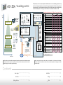
AG-150A
AG-150A
G-50A
G-50A
Comparison
Comparison
between
between
New
New
andand
Conventional
Conventional
PAR-FL32MA
PAR-FL32MA
PAR-FA32MA
PAR-FA32MA
PAC-SE51CRA
PAC-SE51CRA
PAC-YT51CRB
PAC-YT51CRB
PAR-F27MEA
PAR-F27MEA
AG-150A
AG-150A
GB-50A GB-50A
PI Controller
PI Controller
OUTDOOR
OUTDOOR
UNITUNITINDOOR
INDOOR
UNITUNIT
AG-150A
AG-150A
G-50A
G-50A
PAC-YG60MCA
PAC-YG60MCA
PLFYPLFY
PCFYPCFY
PMFY
PMFY
PKFYPKFY
PEFYPEFY
PFFYPFFY
FreshFresh
Air Intake
Air Intake
type type
LGH LGH
GUF GUF
DIDO DIDO
Controller
Controller
Return
Return
air temp.
air temp.
(ambient
(ambient
temp)temp)
Error Error
Fan speed
Fan speed
Air flow
Air direction
flow direction
Filter Filter
sign sign
FloorFloor
layoutlayout
( from( from
USB USB
port) port)
Weekly
Weekly
Schedule
Schedule
Interface
Interface
(LM ADAPTER)
(LM ADAPTER)
BACnet
BACnet
interface
interface
software
software
PAC-YG31CDA
PAC-YG31CDA
ON/OFF
ON/OFF GR GR
Ethernet
Ethernet
PAC-YG63MCA
PAC-YG63MCA
A ir-Conditioning
A ir-Conditioning
Control
Control
System
System
LONWLORKS
ONWORKS
transmission
transmission
line line
Small
Small
scale
scale
Ethernet
Ethernet
Market
Market
sizesize
We We
offeroffer
a wide
a wide
range
range
of air
ofconditioner
air conditioner
management
management
to meet
to meet
all requirements
all requirements
fromfrom
the the
smallest
smallest
andand
simplest
simplest
to the
to the
largest
largest
andand
most
most
complex.
complex.
Among
Among
those
those
controllers,
controllers,
AG-150A
AG-150A
centralized
centralized
controller
controller
covers
covers
the the
application
application
ranges
ranges
fromfrom
middle
middle
to large
to large
sized
sized
buildings.
buildings.
SET SET
�
�
�
�
-
�
�
�
�
-
� *1 � *1
�
�
�
�
�
�
�
�
�
�
�
�
�
�
�
�
�
�
�
�
�
�
�
�
�
�
�
�
SET SET
-
�
�
�
�
�
�
�
�
�
�
�
�
�
�
-
NA NA
NA NA
OP�OP�
OP�OP�
NA NA
Day schedule
Day schedule
can be
can
changed
be changed
without
without
changing
changing
weekly
weekly
or annual
or annual
schedule
schedule
OP�OP�
OP�OP�
OP�OP�
TimeTime
setting
setting
unit unit
1 min1 min 10 min
10 min 1 min1 min
1 min1 min
Today's
Today's
Schedule
Schedule
No.ofNo.of
settings
settings
per day
per day
Item:Item:
ON / ON
OFF,
/ OFF,
Operation
Operation
mode,
mode,
Temp.
Temp.
setting,
setting,
Permit
Permit
/ Prohibit
/ Prohibit
local local
RC, RC,
fan speed,
fan speed,
air-flow
air-flow
direction
direction
24
24
�
�
6
6
24
24
�
�
�
�
NA NA
�
�
�
�
�
�
�
�
ON / ON
OFF,
/ OFF,
Emergency
Emergency
stop stop
12
12
�
�
exclude exclude
fan speed,
fan speed,
air flow direction
air flow direction
(only ON/OFF,
(only ON/OFF,
RC prohibit)
RC prohibit)
External
output
External
output
Integrated
Integrated
centralized
centralized
control software
control software
TG-2000A
TG-2000A
�
�
�
�
�
�
�
�
�
�
�
�
�
�
Max.50
Max.50
days schedule
days schedule
settingsetting
for 24for
months
24 months OP�OP�
ON / ON
OFF,
/ OFF,
Error Error
/ Normal
/ Normal
BACnet
BACnet
transmission
transmission
line line
MITSUBISHI
MITSUBISHI
ELECTRIC's
ELECTRIC's
CITYMULTI
CITYMULTI
can becan
easily
be easily
connected
connected
to the to
building
the building
management
management
system
system
through
through
BACnet
BACnet
.
.
�
�
�
�
�
�
�
�
�
NA NA
NightNight
setback
setback
MA MA
ME ME
R/CR/C
SET SET
�
�
�
�
�
�
�
�
�
� �
OP�OP�
� �
NA NA
NA NA
OP�OP�
Seasonal
Seasonal
schedule
schedule
Annual
Annual
Schedule
Schedule
Scheduling
ST ST
WEBWEB
� �
� �
OP�OP�
Optimized
Optimized
start-up
start-up
control
control
PAC-YG66DCA
PAC-YG66DCA
AI Controller
AI Controller
SR SR
ON / ON
OFF/ OFF
Operation
Operation
modemode
Temperature
Temperature
setting
setting
�
�
�
�
�
�
�
�
�
�
�
�
�
�
External
input
External
input
Middle
Middle
scale
scale
Y :PUHY
Y :PUHY
R2 :PURY
R2 :PURY
WY:PQHY
WY:PQHY
WR2:PQRY
WR2:PQRY
S :PUMY
S :PUMY
Operation
PAC-SF44SRA
PAC-SF44SRA
PAC-YT34STA
PAC-YT34STA
PAC-YT40ANRA
PAC-YT40ANRA
PAC-SC30GRA
PAC-SC30GRA
�
�
�
�
�
�
�
�
�
�
�
�
�
�
ON / ON
OFF/ OFF
Operation
Operation
modemode
Temperature
Temperature
setting
setting
Fan speed
Fan speed
Air flow
Air direction
flow direction
Permit/
Permit/
Prohibit
Prohibit
local local
operation
operation
Monitoring
Large
Large
scale
scale
PAR-21MAA
PAR-21MAA
Unit Unit
AG-150A
AG-150AG-50A
G-50AAG-150A
AG-150AG-50A
G-50A
System
System
ON/OFF
ON/OFFGroupGroup
Remote
Remote
Schedule
Schedule
Remote
Remote Remote
Remote
Controller
Controller
Timer Timer Controller
Controller
Controller
Controller
Scheduling
PAC-YG31CDA
PAC-YG31CDA
(BACnet
(BACnet
IF) IF)
or or
TG-2000A
TG-2000A
Wireless
Wireless
Remote
Remote
Remote
Remote
Controller
Controller
Controller
Controller
SimpleSimple
Remote
Remote
Controller
Controller
C entralized
C entralized
Remote
Remote
Controller
Controller
Operation
Price/
Price/
Spec
Spec
ndividual
I ndividual
Remote
Remote
Controller
Controller
Monitoring
I
NA NA
�
�
�
-
-
-
-
�
-
-
-
-
� 㧦Available
� 㧦Available
NA 㧦Not
NA 㧦Not
available
available
OP�㧦Available
OP�㧦Available
with option.
with option.
License
License
registeration
registeration
required.
required.
SET :SET
Available
: Available
by changing
by changing
the setting
the setting
*1 ON/OFF
*1 ON/OFF
3times/pattern.
3times/pattern.
3pattern+prohibit
3pattern+prohibit
pattern/week.
pattern/week.
WithWith
a new
a new
coloured
coloured
touch
touch
panel,
panel,
newnew
functions,
functions,
andand
continuation
continuation
of all
of the
all the
current
current
G-50A
G-50A
functions,
functions,
AG-150A
AG-150A
visualizes
visualizes
its functions
its functions
fromfrom
basic
basic
control
control
to advanced
to advanced
operations
operations
andand
bringing
bringing
an an
ultimate
ultimate
controller
controller
to reality.
to reality.
Contents
Contents
. . . ................................................................ .3. . 3
New
New
design
design
. . . ................................................................ .1. .7 1 7
Installation
Installation
. . . ................................................................ .4. . 4
Functions
Functions
. . . ................................................................ .1. .8 1 8
Wiring
Wiring
. . . ................................................................1. .5. 1 5
System
System
structure
structure
--
. . . ................................................................ .2. .1 2 1
Q&A
Q&A
--
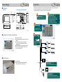
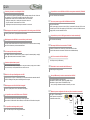
New design
Functions
● Dimension
AG-150A
The need for control is paramount in order to optimize the performance of any air conditioning system.
AG-150A offers a wide range of control functions designed to do just this.
For further information on each function, refer to the pages indicated.
Power Supply Unit PAC-SC51KUA
300 (11-13/16)
25.6
(1-1/16)
271(10-11/16)
90(3-9/16)
44.7
(1-13/16)
72(2-7/ 8)
169(6-11/ 16)
155(6-1/ 8)
130(5-1/ 8)
185 (7-5/16)
NEW
NEW
Function1
P.5~6
T
CENTRALIZED CONTROLLER AG-150A
Function3
P.7~8
Optimum control setting
Seasonal scheduling function
Sliding temperature functions *1 Dec 08
Night setback function *1 Dec 08
Optimized start-up function *1 Dec 08
Operation on Touch Panel
NEW
Function2
*1 AG-150A software needs
to be upgraded.
Apr 09
P.9
272 (10-3/4)
TB2,TB3
TB1
Controllable units
expanded to 50~150
Unit: mm (in)
● Backlight color liquid crystal display
n Easy to see and control.
n Able to identify whether a unit is ON or OFF from a
distance.
n Switches ON when touched or in operation
First touch turns ON the backlight, followed by
operation touch.
n Turns OFF when there is no operation for 10mins
n Turns ON during unit malfunction (Alarm, Error)
when the backlight is OFF.
NEW
Function4
P.10
CSV output of initial
setting, charge, user
info data
Apr 09
Expansion controller
Switching HUB
Apr 09
Expansion controller
Apr 09
Expansion controller
● Back Structure
n Easy installation
n Ways to install-wall embedded/wall mounting
*For further information, refer to page 17
Web/TG-2000A
Function5
VPN Router
P.11~13
Control of Air-conditioners from PC
Remote monitoring PC
(with VPN function)
Internet
Router
Function6
P.14
Monitor/operation from remote site.
Error mail on service person’s cell phone.
--
--
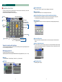
Function1
● Operation on Touch Panel
The new colour touch panel is the ultimate function AG-150A offers which enables easy to monitor and
operate with just touching the panel with your fingers.
Here are the functions available on the colour touch panel.
Setting change button 9
1 Menu bar
Filter sign
2 Sub menu
Number of 8
malfunctioning unit
Group icon
3 Floor-
switching
button
Group name
3
Floor-switching button
4
Zoom-out button
5
Select-all button/Select-all-groups-on-the-floor button/Deselect-all button
6
Operation button
Select-all button
Select-all-groups-on-the-floor button
Deselect-all button
Display size can be reduced. Floors to be displayed can be selected.
Touching each unit with your index finger can select units or if the setting applies to multiple units,
it is also possible to select all units by floor or system and cancel the selection.
After selecting a unit, when you click a unit or this operation button, the display will appear to specify
setting.
7
Operation button 6
4 Zoom-out button
Select the floor to monitor or operate. Floors to be displayed can be selected.
5
Operation by touching with index finger
Operation screen
7
Group icon/Group name
8
Number of malfunctioning unit
9
Setting change button
In order to change operation status, just touch the icon with index finger and an orange box appears around
the unit icon indicating the selected unit.
Each unit and its status are displayed and visible on the touch panel giving the information wanted in
a glance.
To check what kind of error has occurred in the system, click on the yellow exclamation mark at the upper
right corner and the malfunction list appears. To check details, click on [error code] number and a screen
explaining the error will appear.
Multi-language, total of 8
Language can be selected from the following.
Japanese/English/French/German/Spanish/Italian/Russian/Chinese (*English/Spanish only in Ver. 1.01~1.03)
1
Menu bar
2
Sub menu
“Monitor/Operation”, “Schedule Settings”, “Status List”, “Log” can be selected.
Change display between by floors or by block.
Floor layout screen
Initial setting can be changed.
Block display screen
--
--
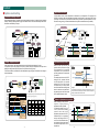
Function2
● Optimum control setting
Night setback Function
Seasonal scheduling function
With a seasonal scheduling, it is possible to set weekly schedule by seasons. 2 patterns of weekly schedule
(Weekly1, Weekly2) and day/month to apply that schedule can be set which automatically shifts when it
reaches the scheduled day of the year.
In night setback function, indoor temperature is maintained to a set temperature. This prevents frost
formation in the winter. When the temperature goes below a specific value, the unit starts in HEAT mode
at low temp. Since the units only start at HEAT mode when it goes below a specific temperature, it is very
effective for energy saving. (Conventional methods:units only start at a decided time set by schedule)
Setting night setback
M-NET
Set seasonal
scheduling
M-NET
M-NET
adapter
AG-150A
PSU
Liquid crystal display
M-NET
OC
AG-150A
A Control
IMAGE
Jan
Change
automatically
Feb
Mar
Apr
May
Jun
[Summer] Stop time
Aug
Sep
Oct
Nov
Schedule 1
8:00
Dec
Setting time zone of control
Schedule 1
28°C/83°F
(Upper limit temp)
Weekly schedule 1
Stop time
18:00
[ON]{HEAT}[14°C/57°F]
21°C/69°F
Indoor temp
22°C/71°F
Group 1
Group 2
<
09:00
䇼ᦐᣣ䇽 䋺
Group 3
< ㆇォ䇭27㷄
09:00
12:00
<Mon>
09:00
12:00
ᱛ
13:00
09:00
12:00
13:00
ㆇォON Cool 24C
12:00 OFF
13:00
13:00 ON
Group 1
Group 2
<
09:00
䇼ᦐᣣ䇽 䋺
Group 3
< ㆇォ䇭27㷄
09:00
12:00
<Mon>
09:00
12:00
13:00 ᱛ
09:00
12:00
13:00
ㆇォON Heat 27C
12:00 OFF
13:00
13:00 ON
[Winter]
[ON]{COOL}[28°C/83°F]
Indoor temp
Schedule 2
Weekly schedule 2
A Control
IC
Liquid crystal display
Change
automatically
Jul
M-NET
OC
PSU
IC
IMAGE
M-NET
adapter
14°C/57°F
(Lower limit temp)
ޣCondition1[ޤIndoor temp] [>] [28°C/83°F]
ޣOperation1[ޤON] [COOL][28°C/83°F]
Group unit
Setting minimum and
maximum temp.
ON 22°C/71°F
OFF
䇼Condition 1[ޤIndoor temp.] [<][14°C/57°F]
䇼Operation 1䇽[ON] [HEAT][14°C/57°F]
ON Cooling 28°C/83°F
ON 21°C/69°F
M-NET
OFF
ON Heating 14°C/57°F
M-NET
AG-150A
Sliding Temperature control
In this interlock function, the outdoor temperature is used to slide the set temperature of a room.
This prevents a person from getting a shock (sick) of sudden change in temperature when they enter a
building from being outside. Also this process is very effective for energy saving.
This function enables to set different max. slide temperature range per group in accordance to the change in
outdoor temperature.
AI Controller
Outdoor Temp.
Set slide temp
M-NET
M-NET
adapter
M-NET
AG-150A
Outdoor
temperature is
measured by
AI controller.
A Control
OC
PSU
IMAGE
Temperature
IC
36°C/97°F
35°C/95°F
34°C/93°F
33°C/91°F
32°C/89°F
31°C/88°F
30°C/87°F
29°C/85°F
28°C/83°F
27°C/81°F
26°C/79°F
25°C/77°F
24°C/75°F
23°C/73°F
*Max. slide temperature range can be selected for each group from below.
[No control] [+1°C] [+2°C] [+3°C] [+4°C]
㪦㫌㫋㪻㫆㫆㫉㩷㫋㪼㫄㫇㪼㫉㪸㫋㫌㫉㪼
㪪㪼㫋㩷㫋㪼㫄㫇㪼㫉㪸㫋㫌㫉㪼㩷㫆㪽㩷㪸㩷
㪾㫉㫆㫌㫇㩷㫎㫀㫋㪿㩷㪸㩷㪤㪸㫏㪅㩷
㫊㫃㫀㪻㪼㩷㫋㪼㫄㫇㪼㫉㪸㫋㫌㫉㪼㩷㫉㪸㫅㪾㪼㩷
㫆㪽㩷㪲㪂㪋°C㪴
㪪㪼㫋㩷㫋㪼㫄㫇㪼㫉㪸㫋㫌㫉㪼㩷㪹㪼㪽㫆㫉㪼㩷㫀㫅㫋㪼㫉㫃㫆㪺㫂
Time
PSU
Optimized Start-up control
㪪㪼㫋㩷㫋㪼㫄㫇㪼㫉㪸㫋㫌㫉㪼㩷㫆㪽㩷㪸㩷
㪾㫉㫆㫌㫇㩷㫎㫀㫋㪿㩷㪸㩷㪤㪸㫏㪅㩷
㫊㫃㫀㪻㪼㩷㫋㪼㫄㫇㪼㫉㪸㫋㫌㫉㪼㩷㫉㪸㫅㪾㪼㩷
㫆㪽㩷㪲㪂㪉°C㪴
--
Max. slide
temperature
range
+1㷄 control +2㷄 control +3㷄 control +4㷄 control
(+1.5㷄 or
(+4.5㷄 or
(+6.5㷄 or
(+7.5㷄 or
above)
above)
above)
above)
No control
+1㷄 control
�
+2㷄 control
�
�
+3㷄 control
�
�
�
+4㷄 control
�
�
�
�
� Control
( ) Difference between the outdoor temperature and original set temperature
With this star t up function, pre
operation will be performed to bring
the temperature to t he spec if ie d
temperature at the specif ied time
providing optimum air environment all
year around.
For example, when it is set as 22°C/71°F
heating at 9:00, operation will start
at 8:45-15min before 9:00, and will
achieve 22°C/71°F at 9:00. AG-150A
will decide when pre-cooling should
start 30 minutes before the target time
based on set/room temp and data of
the past days (when units were turned
ON for optimized start-up control).
OC
Change to [22°C/71°F]
IMAGE
Target time
09:00
Start time is changed
[Winter]
Stop time
22°C/71°F
at the most suitable
time
18:00
21°C/69°F
indoor temperature
14°C/57°F
14°C/57°F
(Lower limit temp)
[ON]{HEAT}[14°C/57°F]
Indoor temp
ޣCondition 2ޤAG-150A study result
ޣOperation 2[ޤON]㨇HEAT㨉[22°C/71°F]
ON 22°C/71°F
䇼Condition 1[ޤIndoor temp.] [<][14°C/57°F]
䇼Operation 1䇽[ON] [HEAT][14°C/57°F]
OFF 14°C/57°F
<Logic>
ON 21°C/69°F
OFF
ON Heating 14°C/57°F
30 minutes before the target time, AG-150A studies the set temp, room
temp, and data of the past days (when units were turned ON for optimized
start-up) and decides when to start the units.
Setback + Optimized start-up control
When combining the two functions
t o g e t h e r, a h i g h l y e f f e c t i v e
temperature control is possible.
For example, setback is set at 14
°C/57°F, unit will start its heating
operation when the indoor
temperature goes below 14°C/57°F.
Simultaneously, if the optimized
start-up control targets 22°C/71°F
at 9:00, AG-150A will decide when
pre-heating should start and obtain
the desired temperature at the
required time.
Stop time
18:00
[ON][14°C/57°F]
Change to [22°C/71°F]
Start time is changed at the
most suitable time
22°C/71°F
Indoor temp
14°C/57°F
14°C/57°F
indoor temperature
䇼Condition1䇽[Indoor temp䌝 [<][14°C/57°F]
䇼Operation1䇽[ON] 䌛HEAT䌝[14°C/57°F]
ON 22°C/71°F
Target time
09:00
OFF
--
ON 14°C/57°F
䇼Condition 2䇽AG-150A study result
䇼Operation 2䇽[ON]䌛HEAT䌝[22°C/71°F]
ON 22°C/71°F
IC
Function3
Function4
● Controllable units expanded
● USB Memory
TENTATIVE
AG-150A has a USB memory slot. Data can be extracted or restored incase there is a fault or resetting a
system.
Maximum of 50 units
Include indoor units, LOSSNAY, DIDO (contacts), PI and AI controller.
*DIDO has 6 contact points. 1 contact point is counted as 1 indoor unit.
*Only 5 PI controllers can be connected to 1 AG-150A.
*Depending on the model, indoor units may be counted as 2 or more units.
Maximum of 150 units
Note : Please use the following USB memory.
Manufacturer : Sandisk, model : SDCZ6-2048-J65RB, 2G Byte
Manufacturer : Kingston, model : DT400/2GBFE, 2G Byte
* We are planning to add brands and models of USB memory in the future.
April 2009
AG-150A software needs to be upgraded and Expansion controller (PAC-YG50ECA) is required.
Power supply for M-NET is included in the Expansion controller.
1
AG-150A
M-NET
PSU
(PAC-SC51KUA)
LAN
(100BASE-TX)
Expansion
Controller
PAC-YG50ECA
2
Backup of Initial setting Data
M-NET
adapter
M-NET
A Control
OC
Max.50
units
Processing of charge parameter
data on PC
AG-150A
USB memory
USB memory
IC
AG-150A
Expansion
Controller
PAC-YG50ECA
PC for processing data
M-NET
M-NET
adapter
M-NET
A Control
OC
Central Control PC
(TG-2000A)
*Proportional division calculation is processed with PC.
Max.50
units
IC
Expansion
Controller
PAC-YG50ECA
Max.150 units
3
Restoring of Initial setting Data
Dec 08
M-NET
adapter
M-NET
A Control
Max.50
units
G-50A
AG-150A
2009/M
AG-150A
USB memory
USB memory
IC
TG2000
Initial setting on PC
AG-150A
M-NET
OC
Controller
4
PC for initial setting
Special SW
*The data from a design tool can be edited.
Connectable maximum no. of units
2000 units
50 units
150* units
*Up to 50 units per Expansion controller, up to 3 expansion controllers
--
- 10 -
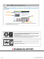
Function5
● Control of Air conditioner from PC
● Comparison between AG-150A WEB and TG-2000A control/monitoring
There are two ways to monitor air conditioner through a personal computer (PC).
One is from AG-150A WEB (Monitoring PC) and another with a TG-2000A (Central control PC).
*In both cases, control/monitor in a private network.
1) AG-150A WEB
Without special software, air conditioners can be controlled over a PC by just connecting a LAN and
registering WEB license. Units can be controlled collectively or in groups, and by blocks or floors. Also,
setting of annual schedule is possible with a license.
Number of AG-150A controlled/monitored per screen: 1 AG-150A (max. of 50 indoor units)
General description
Central Control PC
(AG-150A WEB)
TG-2000A software (Central control PC)
control/monitor
Maximum of 1 AG-150A(ޓ50 units) can be
controlled/monitored. Total of 254 AG-150A
and monitoring PC can be connected to one
LAN system. Screen-display is per AG-150A.
Maximum of 40 AG-150A (2000 units) can
be screen-displayed to control/monitor.
For apportioned electricity calculation,
TG-2000ASoftware is required.
*1.Units include indoor units, LOSSNAY, DIDO, PI and AI controller. DIDO has 6 contact points. (1 contact point is
counted as 1 unit.) Large capacity indoor units are counted as 2 or 3 indoor units.
Daily/ Weekly1/
Weekly2/Annual
schedule
AG-150A WEB control/monitor
AG-150A WEB (Monitoring PC)
control/ monitor
�
�
License registration required
(Weekly1 schedule license unnecessary)
License registration required
Units that can be scheduled: Indoor units, general equipment(ޓSchedules can be copied)
M-NET
LAN
(100BASE-TX)
Switching
HUB
M-NET
adapter
M-NET
AG-150A
PSU
PAC-SC51KUA
A Control
OC
IC
Watt hour meter
PI Controller
�
Apportioned
Electricity
Calculation (charge
data)
NA
Accumulated
operation time
NA
License registration required
(Energy management license)
PI controller required.
�
License registration required
(Energy management license)
�
2) TG-2000A
With TG-2000A software, up to 2000 indoor units can be controlled/monitored.
Compared to the AG-150A WEB, air conditioner layout by room and floor can be displayed and all AG-150A
in one system will be shown enabling easy control/monitoring.
*For AG-150A, a new version TG-2000A (Ver 5.50 or later) is required and a current version cannot be used.
Energy saving/Peak
cut control
General equipment
control
M-NET
LAN
(100BASE-TX)
Switching
HUB
M-NET
adapter
AG-150A
OC
PSU
PAC-SC51KUA
M-NET
Indoor unit/general
equipment operation
display
�
�
(DIDO controller required)
Screen-display
is per AG-150A.
Maximum of 50
units can be
displayed.
PI Controller
A Control
Block display
Available from
Dec. 2008
Floor plan display
- 11 -
(DIDO controller required)
Operation of
maximum 2000
units can be
displayed.
IC
Watt hour meter
License registration required
(Energy management license)
For peak cut control, PI controller is required for electricity monitoring method.
TG-2000A software control/monitor
Central Control PC
(TG-2000A)
�
License registration required
(Energy management license)
- 12 -
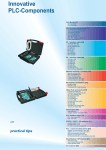
Function6
● Internet connection
AG-150A WEB (Monitoring PC)
control/ monitor
Floor and section display only.
TG-2000A software (Central control PC)
control/monitor
n Enables control and monitor multiple properties from a remote location
n Notification by e-mail to mobile phone or PC
In case floor in divided into four sections.
Web browser
All floor plan display
NA
Global IP address
Internet
VPN router
VPN router
ADSL modem
LAN
ADSL modem
Click general equipment icon for operation
screen.
Click general equipment icon for operation
screen.
SSL authentication function
Encrypted data
Controller Display
(DIDO controller)
Note : . Do not directly connect AG-150A to the Internet.
. Use a security device such as a VPN router when connecting the AG-150A to the Internet to prevent unauthorized access.
. To activate SSL functions use https://h.h.h.h/administrator.html
IP address of AG-150A
Remote monitoring
Present value of
measurement can be
displayed from
[Measurement list].ޓ
Measurementޓ
monitoring
(PI controller)
Present value of
measurement can be
displayed from
[Maintenance of
charge data] - [Present
volume monitor].
T r e n d g r a p h
(electricity only) can
be displayed from
[Tool] - [Graph
display].
Trend graph can be
displayed from [Tool] [Graph display].
Present temp. and humidity can be seen from
[Measurement list].
Measurement
Monitoring
(AI controller)
Monitoring and controlling on PC at desk or even in
remote buildings
No need to check every controller when turning ON/OFF
Reports are provided to the designated e-mail addresses in the events of troubles.
Quick restoration is possible by understanding the causes of trouble in advance.
Present temp. and
humidity is indicated
above the AI controller
icon on the floor plan.
Trend graph can be displayed from [Tool] [Graph display].
- 13 -
AG-150A
Error e-mail
I can check the causes
of trouble without asking
customers.
It is convenient.
AG-150A
AG-150A
Measurement can be
displayed
from [Trend
graph].
AG-150A
AG-150A
- 14 -
AG-150A
AG-150A
System structure
● System structure
1. Management of 50 or less units
same as current system
AG-150A can control up to maximum of 50 units
In case of 51 units or more (Up to 150 units)
April 2009 version
When 50 or less units have to be controlled, AG-150A is connected directly to M-NET (as conventional
G-50A).
Expansion
controller
PLC
Units: include indoor units, LOSSNAY, DIDO (contacts), PI and AI controller.
*DIDO has 6 contact points. 1 contact point is counted as 1 indoor unit.
*Only 5 PI controllers can be connected to 1 AG-150A.
*Depending on the model, indoor units may be counted as 2 or more units.
Expansion
controller
Web function by PC
TG-2000A
M-NET
LAN
(100BASE-TX)
Expansion
controller
Switching HUB
Switching
HUB
M-NET
adapter
Monitoring PC
AG-150A WEB
A Control
OC
PSU
PAC-SC51KUA
LAN
USB memory
M-NET
AG-150A
IC
General Equipment
DIDO Controller
Switching
HUB
LED Lamp
POWER
ON/OFF
In case of 50 units or less
to Air Conditioner
24VDC
Y2
Y1
X2
X1
Z1
Z2
M-NET
AI Controller
Watt hour meter
Central Control PC
(TG-2000A)
Note:New version (ver5.50
or later) of TG-2000A is
required for AG-150A.
Current TG-2000A cannot
be used.
Power supply
PAC-SC51KUA
Temp/Humidity sensor
Up to 5 can be connected
to 1 AG-150A
PI Controller
Switching
HUB
Service company
/Sales office
AG-150A
Internet
Router
with VPN
Router
with VPN
Mobile phone of
service person
Note : Use a security device such as a VPN router when connecting the
AG-150A to the Internet to prevent unauthorized access.
100-240VAC
50Hz/60Hz
2. Management of 51 or more units
Remote monitoring
PC
Apr.2009
When managing 51 or more units, EXPANSION CONTROLLER (EC) is required.
� External input: select A, B or C (on Network setting screen or on Initial setting web)
A
B
C
Level input
Pulse input
Emergency STOP
ON/OFF
*Connection between AG-150A and EC is done using LAN cable (Ethernet)
*50 units can be connected to 1 EC.
*3EC can be connected to 1 AG-150A through Switching HUB.
ON/OFF/Prohibit local operate/Permit local operate
M-NET
PSU
(PAC-SC51KUA)
� External output
One or more IC: ON
ON signal output
One or more IC: Malfunction
Malfunction signal output
LAN
(100BASE-TX)
Expansion
Controller
PAC-YG50ECA
M-NET
adapter
M-NET
A Control
OC
IC
AG-150A
Expansion
Controller
PAC-YG50ECA
M-NET
M-NET
adapter
M-NET
A Control
OC
Central Control PC
(TG-2000A)
Max.50
units
IC
Expansion
Controller
PAC-YG50ECA
M-NET
M-NET
adapter
M-NET
OC
IC
- 15 -
Max.50
units
- 16 -
A Control
Max.50
units
Max.150 units
Installation
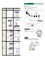
Wiring
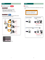
● Installation Method
● DC Power Supply and M-NET Transmission Line
There are two ways to connect AG-150A and Power Supply Unit PAC-SC51KUA.
1) Embedding AG-150A in the wall
To embed AG-150A in the wall, A and
B type installation plate (supplied with
AG-150A) is required.
1. Connection via terminal block
The DC power cable and M-NET transmission line can be connected with a terminal block as the figure
shown below.
AG-150A
M4 roundhead
screw (supplied)
Wall
Power supply unit (PAC-SC51KUA)
Centralized controller
(AG-150A)
Outdoor unit
2) Wall-Embedded installation with an electric box
Inner wall
Electric box (PAC-YG83UTB;
sold separately)
AG-150A
60 mm
(2-3/8 in)
minimum
M4 rounded
screw (supplied)
Building structure
Cable Clamp
Embedding AG -15 0A on
the wall and mounting
i t to e l e c t r i c b ox (PAC YG83UTB).
Electric box is separately
sold optional part.
Wall
M-NET transmission line
(Centralized control line)
DC power supply line (24VDC) *Polarized
Option:
Electric box
(PAC-YG83UTB)
Power supply unit
Back of controller
CN1
3) Wall-mounting AG-150A
To install AG-150A on the
wall, Mounting attachment
B t y p e (PAC -YG 81T B) is
required.
Option:
Mounting attachment
B type (PAC-YG81TB)
TB2
A
Wall
Seal with putty
AG-150A
M4 roundhead
screw (supplied
with the PACYG81TB)
B
S
M-NET
CN1
V+
DC power supply
line (Polarity)
V-
FG
24VDC
CN2
A
CN2
M-NET
B
M-NET transmission
A, B line (Non-Polarity)
Function earthing Shield
(ground) line
S
TB3
V+
Output
V- FG
24VDC
DC power supply line
(Polarity)
PAC-YG81TB (sold
separately) is required
mount installations.
50 m (164 ft) or less
* Use a ring terminal to connect to the terminal block
4) Installing AG-150A and PSU inside the mounting attachment on the wall
M4 roundhead screw
(supplied with
PAC-YG85KTB).
Wall
AG-150A
Mounting attachment A type
(PAC -YG85K TB) is required
when installing AG-150A and
PSU on the wall.
Option:
Mounting attachment A type
(PAC-YG85KTB)
PAC-YG85KTB (sold
separately) is required
in wall mount
installation with both
the controller and a
power supply unit.
Power supply unit
(PAC-SC51KUA; sold
separately)
Screws (supplied with
PAC-YG85KTB)
- 17 -
- 18 -
2. Connection via connector
When installing AG-150A with mounting attachment A type (PAC-YG85KTB) (optional), DC power cable and
M-NET transmission line is connectable via connector using a cable supplied with PAC-YG85KTB.
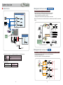
● Wiring Length
1. Management of 50 units
Allowable length of M-NET Transmission Lines and its system configuration are follows.
Power supply unit (PAC-SC51KUA)
L1
Centralized controller
(AG-150A)
AG-150A
DC Power supply
(24VDC)
Length:
max. 50m (164 ft)
M-NET transmission
line (Centralized
controll line)
DC power supply line
(24VDC) *Polarized
L2
2
1
L4
3
M-NET remote controller
L3
4
5
PSU
PAC-SC51KUA
1) Maximum length of M-NET transmission line:
1 L1+L2+L3+ 5+ 1+ 2 ( 3)
500m (1640 ft)
2 L1+L2+L3+ 5+ 4
500m (1640 ft)
3 L1+L2+L4+ 6+ 7 ( 8)
500m (1640 ft)
4
2 ( 3) + 1+ 5+L3+L4+ 6+ 7 ( 8) 500m (1640 ft)
5
4+ 5+L3+L4+ 6+ 7 ( 8)
500m (1640 ft)
2) Maximum power feeding length for the indoor control line:
1
5+ 1+ 2 ( 3) 200m (656 ft)
2
5+ 4
200m (656 ft)
3
6+ 7 ( 8)
200m (656 ft)
3) Maximum power feeding length for the centralized control line:
1 L1
200m (656 ft)*
2 L2 +L3 (L4)
200m (656 ft)
7
6
8
*To supply power to the M-NET
line from PAC-SC51KUA,
connect the power jumper on
outdoor unit to CN41.
CN40
ON
CN41
OFF
Outdoor unit
M-NET remote controller
M-NET transmission line(Centralized control line)
M-NET transmission line (Indoor control line)
Note : If the remote control cable ( 4, 8) does not exceed 10m (32 ft) in length, the length for 4, 8 may not
need to be added to the total length.
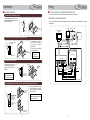
2. Management of 51 or more units
When managing 51 or more units, EXPANSION CONTROLLER (PAC-YG50ECA) (EC) is required.
Refer to the below for wiring restrictions.
AG-150A
M-NET transmission line (Centralized control line)
DC power supply line (24VDC)
*Polarized
Switching
LAN
HUB
100m/328ft
100m/328ft Expansion
controller
PAC-YG50ECA
D1 50m/164ft
PSU
M-NET
Wiring length is same as
conventional system
200m/656ft
100m/328ft
100m/328ft Expansion
controller
PAC-YG50ECA
100m/328ft
100m/328ft Expansion
controller
PAC-YG50ECA
200m/656ft
* AG-150A is connected to Expansion controller (EC)
D1 (24VDC) < 50m/164ft if connected via terminal
- The cable for M-NET is not connected to AG-150A
via LAN cable.
(LAN cable : Category 5 or above cable)
* The length of transmission line can be lengthened by adding switching HUB.
(Can not use Repeater HUB)
* There is no limitation in the number of cascade connection when using a switching HUB.
Recommended cascade connection is 3.
(In the case of 3 cascade, the maximum length between AG-150A and EC is 400m/1312ft.)
NOTE
If the remote contr
total length.
● Precautions
All electric work must be performed according to local regulations.
Improper electrical work may result in electric shock or fire.
Be sure to shut off the power source of the unit and all other units to be connected to
the power supply unit before wiring.
Do not connect AC power line to M-NET and POWER (24VDC) terminal blocks of
AG-150A. Otherwise, the unit may fail.
- 19 -
- 20 -
Q&A
Q1 How many units can be controlled by AG-150A?
50 units. But use of expansion controllers (EC) allows controlling maximum 150 units. 50 units can
be connected to 1 EC so max.3EC is required to control 150 units by AG-150A.
Controllable units include, indoor units, LOSSNAY, DIDO, PI and AI controller.
*DIDO has 6 contact points. 1 contact point is counted as 1 indoor unit.
*Only 5 PI controllers can be connected to 1 AG-150A.
*Depending on the model, indoor units may be counted as 2 or more units.
Q2 What happens when someone forgets the password of initial setting screen of AG-150A?
Contact your sales office. A special password will be released.
Q3 What happens when AG-150A is connected directly to the Internet?
AG-150A could be hacked. Please use a security device such as a VPN router when connecting
the AG-150A to Internet to prevent unauthorized access.
Q10 Is it possible to connect AG-150A and G-50A in same system controlled by TG-2000A?
Yes. Use TG-2000A Ver.5.50 and above.
Q11 Can we use power supply unit PAC-SC50KUA with AG-150A?
No. Use PAC-SC51KUA.
24VDC power supply is required to drive AG-150A. Conventional G-50A used 12VDC to drive
controller and this 12VDC was supplied by PAC-SC50KUA. So since PAC-SC50KUA does not
supply 24VDC, it cannot be used with AG-150A.
Q12 Is it possible to put units in Refrigerant status check mode automatically?
No. You need to do it manually.
Q13 How many AG-150A can be connected to TG-2000A?
Same as conventional G-50A, 40 AG-150A can be connected to TG-2000A.
(Total of 2000 units can be connected to TG-2000A to be controlled/monitored.)
Q4 Is license required for weekly schedule?
No. Weekly schedule is a standard function. License is required for seasonal (weekly1, weekly2),
yearly, daily schedule, and when connected to TG-2000A.
Q14 Can PC be connected to AG-150A via USB port?
No. USB port is only for USB memory.
Q5 How does optimized start-up work?
AG-150A studies the set temp, room temp (return air temp) and the data of past days (at what conditions
the optimized start-up executed) and decides when to switch on the units.
Q6 What is the life span of backlight and color LCD?
Design life span is 13 years. To maintain long life, it is required to activate the automatic switch off
function of backlight. We also plan to have backlight as a service parts.
Q7 What happens when LCD of AG-150A is damaged?
There is no spare part for LCD. AG-150A needs to be changed.
Q8 Is it possible to connect AG-150A to current TG-2000A?
No.You need TG-2000A Ver.5.50 and above to connect to AG-150A.
Since version of G-50A and AG-150A are different, new TG-2000A ver.5.50 and above is required.
Q15 What kind of data is extractable with USB memory?
Initial settings and charge parameter.
Q16 Can any USB memory be used to extract data from AG-150A?
No. Specified USB memory should be used.
Manufacturer : SanDisk, model : SDCZ6-2048-J65RB, 2G Byte
Manufacturer : Kingston, model : DT400/2GBFE, 2G Byte
*We are planning to add brands and models of USB memory in the future.
Q17 What’s the system configuration like when only 50 or less units are connected?
AG-150A is connected directly to
M-NET (same as the conventional
centralized controller G-50A.)
M-NET
M-NET
M-NET
adapter
A Control
AG-150A
PSU
OC
IC
PAC-SC51KUA
Q9 Is it possible to send charge data by e-mail?
General Equipment
DIDO Controller
No. Use USB memory to extract charge parameter data.
Temp./Humidity sensor
AI Controller
Watt hour meter
- 21 -
- 22 -
PI Controller
Q18 What’s the system configuration like when more than 50 units are connected?
AG-150A connected to
M-NET via Expansion
Controller.
Q21 Where is the serial number for AG-150A indicated?
Serial number is indicated in two places. One on the packaging box and another can be seen at the
lower right corner when taking off the AG-150A cover.
M-NET
PSU
(PAC-SC51KUA)
LAN
(100BASE-TX)
Expansion
Controller
PAC-YG50ECA
M-NET
adapter
M-NET
Max.50
units
A Control
OC
IC
April 2009
AG-150A
Expansion
Controller
PAC-YG50ECA
M-NET
M-NET
adapter
M-NET
Max.50
units
A Control
OC
Central Control PC
(TG-2000A)
Max.150 units
IC
Expansion
Controller
PAC-YG50ECA
M-NET
M-NET
adapter
M-NET
Max.50
units
A Control
OC
IC
Q22 What should be done if the touch panel has a poor reaction?
Q19 How many AG-150A can be connected to 1 power supply unit (PAC-SC51KUA)?
One AG-150A can be connected.
To adjust touch panel, go to the Initial setting, [Maintenance] and [Touch Panel Calibration] to bring
up the Touch Panel Calibration screen.
For further instruction, refer to the AG-150A Instruction Book.
Max.connectable number of controller when using PAC-SC51KUA
Centralized controller
Other system controllers
AG-150A
G-50A
GB-50A
ON/OFF
remote controller
1
-
1
5
System controller, Schedule timer, Group
remote controller
Start calibration
button
10
Max. connectable number of controller when using PAC-SC51KUA
Total number of ON/OFF remote controller
When connecting 1 AG-150A
Total number of System remote
controller, Schedule time,
Group remote controller
0
1
2
3
4
0
�
�
�
�
�
1
�
�
�
�
�
2
�
�
�
�
3
�
�
�
�
4
�
�
�
5
�
�
�
6
�
�
7
�
�
8
�
9
�
5
Q20 Is it possible to monitor and operate general equipments from AG-150A?
Yes. To connect general equipment use DIDO (PAC-YG66DCA)
- 23 -
- 24 -
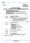
- 25 -
AG-150A demonstration site
Access
http://wwwl1.mitsubishielectric.co.jp/wink_doc/wink_files/acr/menu/ag150/
from your PC.
Explanation
AG-150A unit
WEB
Installation image
This demonstration site covers the primary functions AG-150A possesses and gives users
fundamental experience of AG-150A.
The Air Conditioning & Refrigeration Systems Works acquired ISO 9001 certification under Series
9000 of the International Standard Organization (ISO) based on a review of Quality , management for
the production of refrigeration and air conditioning equipment.
FM 33568 / ISO 9001;2000
ISO Authorization System
The ISO 9000 series is a plant authorization system relating to quality management as stipulated by
the ISO. ISO 9001 certifies quality management based on the "design, development, production,
installation and auxiliary services" for products built at an authorized plant.
The Air Conditioning & Refrigeration Systems Works acquired environmental management system
standard ISO 14001 certification.
The ISO 14000 series is a set of standards applying to environmental protection set by the
International Standard Organization (ISO).
Certificate Number EC97J1227
http://Global.MitsubishiElectric.com
MEE08K043
New publication effective Jan. 2009
Specifications subject to change without notice