1
TABLE OF CONTENTS
IMPORTANT SAFETY PRECAUTIONS .........................................
BEFOREYOU BEGIN ......................................................................
".................
1
2
ASSEMBLY.............................................................................
ADJUSTING THE CROSS TRAINERe ..........................................................
3
8
OPERATING THE STEPPERCONSOLE .........................................................
OPERAllNG THE PERSONAL TRAINER COMPUTER ...............................................
Calories ............................................................................
EXERCISEGUIDE........................................................................
TROUBLE-SHOOTING AND MAINTENANCE ..................................................
ORDERING REPLACEMENTPARTS.....................................................
UMITEDWARRANTY ................................................................
IMPORTANT
WARNING: To _luce
SAFETY
10
11
12
16
25
Back Cover
Back Cover
PRECAUTIONS
the risk of serious injury, read the following important safety precauffonsbefore using the
CROSSTRAINERe. Before beginning any exercise program, consultyour physician. This is especially important for
persons over the age of 35 or personswith pre-exisHnghealth problems. SEARSassumesno responsibilityfor personal injury or properly damage sustained by or through the use of this product.
1.
Read this owner's manual and the accompanyingFITNESSJOURNAL carefully before using the CROSSTRAINERe.
Use the CROSSTRAINER e only as described.
2.
Inspectand tighten all paris each Hmeyou use Ihe CROSS TRAINERe. Repla_:eany worn paris immediately.
3. Do notusethe h'ansformerif it isdamaged. Keepthe powercordaway fromwalkwaysand heatedsurfaces.
4.
Keep your hands away from moving ports. Always wear athletic shoesfor foot protection.
5.
Keep small children away from the CROSSTRAINER• at all times.
6.- To prevent damage to the weight system,do not put any pressureon the leg developer, arms or cables while the
weight setllng is changing.If the lot bar or rower bar is attached to the high pulley stotion,restit in the rack near the
high pulley station. (See OPERATINGTHEPERSONALTRAINERCOMPUTERon page 11 of this owner's manual).
7.
Always stand on the foot plate when performing any exercise that could cause the CROSSTRAINERe to tip.
8.
Make sure that the cables remaln in the grooves in the pulleys as you use the CROSSTIU_NER e.
9.
The resistancecylinders become very hot during use. Allow the resistancecylinders to cool before touching
them. Cover the floor beneath the stepper for protection; a small amount of oil leakage is normal for hydraulic
cylinders. When using the stepper, keep your feet on the pedals at all times. If you lift your feet off the pedals,
the pedals may become separated from the resistancecylinders, resulting in iniury.
10. If you feel pain or dizziness at any time while exercising, stop immediately and begin cooling down. Find out
what is wrong before continuing.
BEFORE
YOU
BEGIN
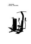
Congrafulatlons for purchasing the revolutionaryPROFORM" CROSS TRAINER e. The CROSS TRAINERe combines a
multi-stationweight systemwith a full-size stepperto let you enjoy true cross training workoutsin the convenience of
your own home. And fo help you get the mostfrom every workout, the CROSS TRAINERe features the advanced PERSONAL TRAINERTM weight training computer.Whether your goal is _mproved cardiovascularfitness,a shapely, toned
body or dramatic musclesize and strength,the CROSS TRAINER e will help you to achievethe specificresultsyou want.
Foryour safely and benefit, read this owner's manual and the accompanying FITNESSJOURNALcarefully before using
the CROSS_AINER e. If you have additional questions,please call our Customer ServiceDepartment toll-flee at
1-800-999-3756, Monday through Friday, 6 a.m. until 6 p.m. Mountain Time (excludingholidays). To help us assist
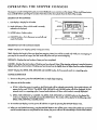
you quickly, please note the model number and serial number of your CROSS TRAINERe before calling. The model
number is 831.15934 i. The serial number can be found on a decal attached to the CROSSTRAINER e. The rotation of
the decal is shown in the drawing below. Write the serial number _n the following space for reference:
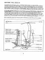
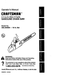
Beforereading further, please review the drawing below and familiarize yourself with the parts that are labeled.
High Pulley Station.
Cable Clip
Lat Bol
Stepper Consa_e
Stepper Handle
CUSTOM SMART CARD
PERSONAL TRAINER Corn
Backrest
Arm
Seat
Resistance
Cyllnder_
LegDeveloper
SelectorKnob
Sfepper
Serial No. Decal
Low Pulley Station
Foot Plate
2
ASSEMBLY
Assembly requires two persons.To assemblethe CROSS TRAINER e, usethe includedvideocassetteor follow the
instructionsbelow. Due to the weight of the CROSS TRAINER e, it shouldbe assembledin the locationwhere it will be
used. Place all parts in a cleared a_-,a and remove the packing materials. Do not disposeof the packing materials until
assembly iscompleted.Make sure ta lawer the resistancecylindersand pedals before beginning assembly; if the
resistance cyfindersfall, they may damage the side shields. Read each assemblystepand examine each drawing
carefully. Referta the Part Identification Chart accompanying this owners manual, to help idenfi_/the hardware used in
assembly. Make sure that all parts are orlenled as shown in the drawings.
The followlng loals (not included)are required for assembly:,two 8" Adjustable Wrenches _
Rubber Mallet _.
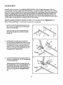
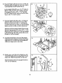
1.
and a
A small amount of soapy water is also required.
Set the Front Base(7) .andthe Rear Base (8) on the
floorasshown.Turn the Rear Base so the indented
holesare toward the floor.
8
Insert seven3/8" x 2 1/2" Carriage Bolts(1) up
through the indicated holesin the Front and Rear
Bases (7, 8).
1
7
I
2
2.
With the help of a secondperson,set the Tower
Frame (10) near the indicated ends of the Front and
I0
Rear Bases(7, 8). The Tower Frame mustbe turned
so the Pedals (75, 76) are on the some side as the
extension on the Front Base. Raisethe Tower Frame
and lower it onto the two indicated3/8" x 2 1/2"
Carriage Bolts(1) in the Rear Base.
3
3.
Raise the front of the Tower Frame (10) and lower it
onto the two indicated 3/8 _'x 2 1/2" Carriage Baits
(1) in the Front Base(7).
Adjust the positionof the Tower Frame (10) so the
fourindicated 3/8" x 2 1/2' Carriage Bal_(1) ore
centered in the slottedholesin the Tower Frame.
Thread a 3/8" Nut (2) with a 3/8" Iockwasher (3)
onto each Carriage Bolt. Do not fighlen the Nuls
yet.
3
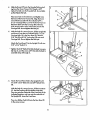
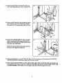
4. Slide the Brace(29) ontothethreadedboltprotruding fromthe TowerFrame(10). Threada 3/8"
N/lock Nut (6) ontothe threaded bolt.Do notfighten the Nylock Nut yet.
4
29\6
Place your foot on the extension and sl_gh_raise
the front ofthe Tower Frame (10). Align the lower "
end of the Brace (29) with the indicated 3/8" x
2 1/2" Co,age
Bolt (1). Lowerthe Tower Frame so
the Brace slidesonto the Carriage Bolt. Thread a
3/8" Nut (2) with a 3/8" Lack'washer(3) onto the
Carrloge Bolt. Do not tighten the Nut yet.
5. With the helpof a secondperson,llftthe Upright(9)
and lowerif ontothe two indicated 3/8" x 2 I/2"
Carriage Bolts(1) in the Rear Bose(8).Thread a
3/8" Nut (2) ancl 3/8" Lockwasher
(3) onto each
Carriage Bolt.Do not lighten the Nutsyet.
s
il
I.I
Attach the FrontBose(7) to the Upright(9) with two
3/8" x 3/4" Bolts(31).
_J .tighten the 3/8"
Nylock Nut (6) attached in assem-
bly step 4, and the seven 3/8" Nuts (2) a,ached in
assembly steps 3 through 5.
• 6.
Attach the Foot PIo_ (102) to the Upright (9) with
two 3/8" x 3/4" Bolts (31) and 3/8" Nylock Nuts
(6).
With the help of a secondperson, lift the Front Bose
(7). Peel the backing off three Rubber Pads (48).
Presstwo onto the undersideof the Front Bose in the
indiealed locations, and one onto the underside of
the Upright (9). Lower the Front Bose.
31___6
Presstwo RubberPods(48) ontothe RearBose(8)
in the somemanner.
4
_
48
.
Insert the lower enc[of the LeftArm (15) into the left
side of the Moment Ann (74). Make sure that the
bracket on the end of the LeftArm is positionedas
shown in the insetdrawing. If the bracket is nat
positioned as shown, the LeftAnn willnot function
properly.
Top a 3/4" PlasticCap (57) onto one of the ends of
a 3/4" x 4" Axle (54). Align the hole in the end of
the LeftArm (15} with the holes in the Moment
(74). Insert the Axle into the Moment Arm and the
LeftArm. Tap a 3/4'
15
PlasticCap onto the Axle.
Nole: An extra 3/4" Plastic Cap (57) has been
included with the hardware pock. If you accldenlal-
,/"
/
[
/
C_rrect position of Arms
against Moment Arm
ly damage one of He Caps during assembly, use
this extra Cap. Otherwise, the extra Cap may be
discarded.
Attach the Right Arm (16) in the same manner.
74
INCORRECI"
8
8.
Wrap the Weight Cable (52) under a 3 1/2" Pub/
15).Attach the Pulleyand a Cable Trap (67) to the
back of the Upright (9) with a 3/8" x 1 3/4" Bolt
(40) and 3/8" Nylock Nut (6). Make sure that the
Cable Trap is in the "7 o°dock" position.
Laythe Weight Cable (52) over a 3 1/2' Pulley(51.
_toch o Cable Trap (67) and the Pulley to the I_
side of the Upright (9) with a 3/8" x 1 3/4" Bolt
(40) and 3/8" Nylock Nut (6). Make sure that the
Cable Trap is in the "12 o'cbck" position.
Wrap the Weight Cable (52) around a 2" Pulley(4).
h'_ch the Pulleyto the LeftAnn (15} with a 3/8" x
1 3/4" Bolt (40} and 3/8" Nylock Nut (6).
9.
9
Wrap the Weight Cable (52} around a 2 3/4"
Pulley1131.,_ach the Pulleyto the indicated bracket
on the Upright 19) with a 3/8" x 1 3/4" Bolt(40)
and 3/8" Ny!ock Nut (6).
5
CORRECT
10. Wrap the Weight Cable (52) around a 2" Pulley (4).
Attach the Pulleyto the RightArm (16) with a 3/8" x
1 3/4" Bolt(40) and 3/8" Nylock Nut (6).
Lay theWeight Cable (52) over a 3 1/2' Pulley(5).
Attach a Cable Trap (67) and the Pulley to the side
of the Upright (9) with a 3/8" x 1 3/4' Bolt (40)
and 3/8' Nylock Nut (6). Make sure that the Cable
Trap is in the "12 o'clock" position.
11. Wrap the Weight Cable (52) under a 2" Pulley (4).
Attach the Pulleyto the bracket on the side of the
Moment Arm (74) with a 3/8" x 1 3/4" Bolt(40)
and 3/8" Nylock Nut (6). Make sure that the Weight.
Cable is between the Pulleyand the indicated tab.
Attach the end of the Weight Cable (52) to the right
side of the Leg Developer (23) with a 3/8' x 2 1/4"
Boil (45) and 3/8" Nylock Nut (6). Do not over'llghten the Nylock Nut, the Cable must be able Io swivel freely or it will be damaged.
12. Insertthe threaded bolt on the end of the Weight
Cable (52) into the Adjustment Bracket (53). Finger
12
tighten the 5/16" Nut (82) onto the threaded bolt
until there is slight tension in the Cable.
13. Wet the upper ends of the left and Right Arms (15,
16) and the insidesof the two Large Pads (17) with
soapy water. Slide the Large Pads onto the Arms.
13
17
Altoch the Backrest(19) to the Upright (9) with two
1/4' x 2 1/2" Bolts (46).
1
6
14. Attach the Seal (28} to the Upright (9) with the two
1/4" x 5/8" Baits (20} and a 1/4" x 2" Bolt(118).
14
15. Center one Pod Tube (22) in the Upright (9), and the
other Pod Tube in the Leg Developer (23). Slide the
four Small Pads (17) onto the ends of the Pad Tubes.
9
16. Restth.eLeftand Right Pedals (75, 76] on the honks
• at the lower ends of the ResistanceCylinders (84).
//17
16
Make sum that the hooks are f_ily inserted into the
same slots under both Pedals.
84
39,
Hug theTransformer(39) intothejackIocalednear
thebottomof theRightSideShield (12).
76
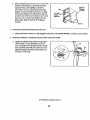
17. Make surethat all padsare properlytightened.Theuseof all remainingpadswill be exploinedin ADJUSTING
THE•CROSS
TRAINERe, beginningon page8 of thisowner'smanual.
18. Before using the CROSS TRAINER e, test the cables and the pulleys.Make sure that the cables are ;n the grooves
in the pulleys. If the cables do not move smoothlyover the pulleys, locate and corred the problem before using
i the CROSS 1RAINER e. If the cables are not properly routed, they will be damaged when used.
7
ADJUSTING
THE
CROSS
TRAINER
e
The CROSS TRAINER • is deslgned to be changed from stationto station quickly and easily. The instru_ons
below
describe how each part of the CROSS TRAINER e can be adjusted. Please read these insf'nJdlonscarefully before using
the CROSS TRAINER e. ReFerto pages 17 through 24 of this owner's manual to see how the CROSS TRAINER • should
be set up for each individual exercise.
IMPORTANT: For effecffve exercise, the CROSSTRAINERe must be set up correctly for each exercise. When attaching the lat bar, rower bar or strap, attach them directly to the CROSS TRAJNER• or use the chain Io attach them;
make sure that the lat bar, rower bar or strap is in the coned starting Pasi_on for each exercise. If there is any
slack in the cable or chain as you perform an exercise, the effecffvenessof the exercise will be reduced.
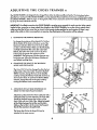
1.
CHANGING
THE STEPPING RESISTANCE
1"ochange the resisfanceof the Pedals (75, 76)° first
llft the Pedals off the hooksat the lower ends of the
ResistanceCylinders (84}. Move the hooksto different slots under the pedals. Make sure that the hooks
10
are fully inserted into the some slats under beth
Pedals. The farther the hooks are from the Tower
Frame (10}, the greater the resistancewill be.
7
WARNING: The ResistanceCylinders become very
hot during use. Allow the ResistanceCylinders fo
cool before touchlng them.
2,
84
CHANGING THE ARMS TO THE BUT/'ERFLY
MODE AND PRESSMODE
The Arms (15, 16) can be changed to either the butlerfly mode or the press mode. To perform the BUTTERFLYexercise, change the Arms to the butterfly
mode by tumlng the Seledor Knob (55) clack'wise as
shown by the decal. To perform the BENCH PRESS
exercise, change the Arms ta the press mode by
tumlng the Selector Knob counterdockwlse.
3.
55
AI"I'ACHING THE/.AT BAR, ROWER BAR OR
STRAP TO THE HIGH PULLEY STATION
33
Attach the Lat Bar (36) to the Main Cable (51) with a
Cable Clip (33). For some exercises, the Chain 138)
should be attached between the Eat Bar and the
Main Cable with two Cable Clips. Adjust the length
of the Chain between the Eat Bar and the Main
Cable so the bat Bar is in the €orred starting position for the exerc|se to be performed.
The Rower Bar (34} or the Strap (35) can be
attached in the somemanner.
8
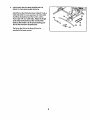
4.
ATTACHING THE I.AT BARI ROWER BAR OR
STRAPTO THE LOW PULLEYSTATION
Altach the tat Bar (36) la the Main Cable (51) with a
Cable Cllp (33). For some exercises,the Chain (38)
should be attached between the tat Bar and the
38
Main Cable with two Cable Clips. Adjust the length
of the Chain between the/,at Bar and the Main
Cable so the tat Bar is in the correct starffng posiffon for the exercise to be I:_'formed.
33
The Rower Bar (34} or the Strap (35) can be
affached in the some manner.
9
OPERATING
THE
STEPPER
CONSOLE
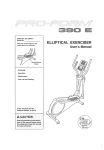
The stepper console is designed to 91ve you instantfeedback as you exercise on the stepper. PTeoseread these instructionscarefvlly before operating the console. Note: Removethe clear plastic from the front of the console.
DIAGRAM OF THE CONSOLE
1. LCD dispk_F-Display
for all modes.
2. Mode incllcolors--Show which mode is currently
selectedand displayed.
3. MODE button--Seleds modes.
OISTANCE
CALORIE
MODE
.4. ON/OFF buflon--Tums the power on and off, and
resetsthe display.
3
I
SC.AN
ON/OFF
II
1
4
DESCRIPTION OF THE CONSOLE MODES
SPEED--Displays your stepping speed, in stepsper minute.
TiME--Displays the length of time you have been stepping. Note: Time will be counted only while you are stepping. If
you stop for ten secondsor longer, the TIME mocle will pause until you resume stepping.
DISTANCE--Displays the total number of stepsyou have completed.
CALORIE--DIsplays the total number of Caloriesyou have burned. Note: If the stepping resistanceis near the lowest or
highestsetting,the aduol number of Caloriesyou have burned may be stlgh_, lower or higher ?nonthe number displayed.
SCAN--Displays the SPEED,TIME, DISTANCE and CALORIE modes, for five secondseach, in a repea_ng cycle.
CONSOLE OPERATION
1. To lure on the Power, press the ON/OFF buffonor simply begin stepping.
2. Selectone of the five modes:
o.
_When
thePower is lumed on, the SCAN mode willbeselected
automatically. One mode indlcatar will
appear by the word 'SCAN." The SPEED,TIME, DISTANCE and CALORIE modes will all be displayed, for five
secondseach, in a repeating cycle. A secondmode indicator will show which mode is currency displayed.
b. SPEED,TIME, DISTANCE or CALORIE--The SPEED,TIME, DISTANCE or CALORIE mode con be selected for
continuousdisplay by repeatedly pressingthe MODE button.The modes will be selected in the following order:.
SPEED,TIh_, DISTANCE, CALORIE, SCAN.
3. To reset the LCD display, turn the Power off and then on ogoln by pressing the ON/OFF button Iw[ce.
4. When you ore finished exercising,press the ON/OFF buttonto turn off the power. Note: If the pedals ore not moved
and the consolebuttonsore not pressedfor four minutes,the power will tum off oulomolically to conservethe battles.
10
OPERATING
THE
PERSONAL
TRAINER
COMPUTER
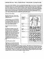
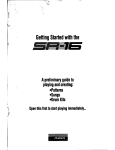
The heart of the CROSS TRAINER • is the advanced PERSONAl.TRAINER weight troining compufer.With the PERSONAL TRAINERcomputer, you can change the weight settingwile a touch of a button. As you exercise,lie compuferwill
measureyour range oFmotion, show the number of Calories you have burned and keep frockof _ repetitionsand
setsyou have complefod. In fee trainer mode, you can select a specificmusclegroup, and the computer will guide you
through o seriesof exercisesfeat will develop the selected musclegroup. Using lee included CUSTOM SMART CARD,
you can create customexerciseprograms and store them in memory for futureworkouts.PreprogrammedSMART
CARDScan also be purchasedto help you achieve specificexercise goals. See the included brochure for more informarion. Pleaseread these ;nstru_ons carefully before operating lie computer.
TURNING ON THE POWER
Pluglie translorrner into a 120-yah outlet.
All indicators and displays on lie computer
will flash three times.
PERSONAL
TRAINER
To turn:on the power, pressthe POWER bulIon. The four displays and various indicators
on lee _pufer
will light. The systemmotor
may be heard while lie weight systemrecalibrates. Note: Always turn on the power
when using the CROSS TRAINERe.
Computer
Muscle
Chart
SELECTINGTHE TONE OR STRENGTH
MODE
Displays
The PERSONALTRAINER computeroffers
bole a tone mode and a strengthmode. If
Slroke
Meter
your goal is to tone your muscles and develop endurance, lie tone rno_e shouldbe
selected. If you wont to increasethe size and
strengthof your muscles,the strengthmode
shouldbe selected.When the power is
lurnedon, the lone mode will be selected
automatically.The tone indicator will light.
To selecl Ihe sfrength mode, presslee
STREI',.IGTH
butlon. The strength indicator will
.;_ light.
Iodicato_
_,,o
• o
-_:
Indicators
:p
•
I
r
0
-
.o..I-
USING THE MANUAL MODE
0
When the power is turned on, the computer
will be in lie manual mode. The lower port
of lee computershows 20 exercises teat con
be performed on lie CROSS TRAINER e. The indlcalor on exercise I will be flashing. Pressthe right or left arrow on
lee NEXT button until the indicator is flashingon the first exercise that you want to do. The number of lie exerciseliat
you seled will be shown in the CALORIES/EXERCISENO. display. Note: For help selecting on exercise, refer to lie
, musclechort on lie upper port of the computer.Presson the musclegroup liot you want to exercise--be sure to press
on lie circled letter. As long as you continueto presson the muscle group, indicatorswill ligld on Ibe lower part of the
computerto showyou which exercise(s)will developIhe seledod muscle group.
11
Next, press the TONE or STRENGTH button, depending on whether you wont the first exercise to be o tone or a strength
exercise. The WEIGHT display will show the recommended weight setting for the exercise that you have selected.
WARNING: The recommended weight settng may be too high or too low far you, depending upon such fadors as
your body size and physical condition. If you cannot complete the desked numbers of sets and repetitions, the
weight setting should be decreased. The weight settingcan be changed by pressingthe increase or decrease button
beneath the WEIGHT display. Each time one of the buttons is pressed, the weight settingwill change by 1 pound. The
buttons can be held down to change the weight setffng quickly. (The weight range for the BENCH PRESSexercise is 30
to 250 pounds;the weight range for all otherexercises is 15 to 125 pounds.)
IMPORTANT: While the weight setting is changing, the motor will be heard and the SETSand REPSdisplays will show
a rapid/y relating indicator. To prevent damage to the weight system,do not put any pressure on the leg developer,
arms or cables while the weight setting is changing, if the lot bar or rower bar is attached to the high pulley station,
rest it in the rack near the high pulley station. If the computer senses pressure on the weight system while the weight
settng is changing, trio WEIGHT display will show an error code ("EEE")far two seconds, and the welght setting will
stop changing. The WEIGHT display will then show the current weight settng. Make sure that there is no pressure
on the leg developer, arms or cables. Pressthe increase or decrease button beneath the WEIGHT display again to
change the weight setffng as desired. Wait for the sound of the motor to stop before you continue.
The SETSand REPSdisplays will show the recommended numbersof setsand repetitionsfor the exercise that you have
selected. If desired, the number of setsor repetitionscon be changed by pressingthe increase or decrease button
beneath the SETSor REPSdisplay. Each time one oFthe buttons is pressed, the number of sets or repetitionswill change
by 1. The range oF sets is 1 to 9. The range of repetitionsis 2 to 20.
Begin the exercise that you have selected. (Refer to pages 17 through 20 of this owner's manual for information about
the proper form for the exercise.} During your first repetition, the computer will measure your range of mation_try to
move through the full range of motion for the exercise.During each following repetition, the STROKE meter will show
your range of moti_
to reach 100% during each repetition.As you exercise, the SETSand REPSdisplayswill show
the numbersof setsand repetitions remainlng to be completed. One tone will sound after each repetition iscompleted,
Iwo tones will sound offer each set is completed, and three toneswill sound after oil repetitions and setshave been compbted. In addition, the CALORIES indicator will I_ght,and the CALORIES/EXERCISENO. display will show the number of
Calories thatyou hove burned.
IMPORTANT:For effac_ve exercise, rest for 1 minute after each set if you are doing a tone exercise, and 3 m_nutes
after each set if you are doing a strength exercise. Your body will burn Calories at all times--at an increased rato
while you are performing repetitions, and at a decreased rate while you are resting. As soon as you begin the first
exercise, the computer will begin counting the Calories you are burning, both wh_e you are performing repetitions
and while you are resting. In order to find the number of Calories you bum during your workout, note the number
that isshown as soon as you completeyour last exercise.
• After you hove completed all of the repetitionsand sets for the first exercise that you selected, press the right or left
arrow on the NEXT button to selectthe next exercisethat you want to do. Repeat the procedure described above for the
nextexercise. (Note: If you select an exercise that involvesonly one arm or leg, such as the SINGLE LEGCURL exercise,
the numbersof repetitions and sets shown in the SETSand REPSdisplays should be performed once using the right arm
or leg, and once using the left arm or leg. After completing the repetitionsand sets using one arm or leg, press the right
arrow on the NEXT button, then press the left arrow on the NEXT button, and then repeat the repeti_onsand sets using
theother arm or leg.) Selectas many exercises as desired until your workout is completed.
USING THE TRAINER MODE
Pressthe TRAINER button. The trainer indicator will light, Next, refer to the musclechart on the upper part of the cam°
puter. An indlcator will be lighted on muscle group 'A." If you want to exercise a different muscle group first, press on
the desired muscle group--be sure to press on the circled letter.
12
Once you have selected the first musclegroup thatyou want to exercise, refer to the lower part af _e computer.One or
mare indicatorswill be lightecl, showing you which exerclse(s)to do to develop the selectedmusclegroup. One of the
indicatorswill be flashing to show you which exercise to do first. If you want to skip the first exercise,pressthe right
arrow an the NEXT button until the indicator is flashingon the exercise that you want to do first.The number of the
exercise will be shown in the CAi.ORIES/EXERCISENO. dispk_y.Next, pressthe TONE or STRENGTHbutton,depending on whetheryou want the first exercise to be a tone or a strengthexercise. The WEIGHT d_spl_ will show the recarnmendedweight settingfor the first exercise. If desired, the weight settingcan be changed. This can be dane in the
same manner as when the computer is in the manual mode. The SETSand REPSdisplays will show the recommended
numbersof setsand repetitions for the first exercise. If desired, the number af sets or repetitions can be changed. This
can be dane in the same manner as when the computeris in the manual mode.
Beginthe first exercise. As you exercise, the campuS' willprovide the same foec_0ackas when it is in the manual mode.
A/ter you have completed all of the repetitionsand sets for the first exercise, pressthe right arrow on the NEXT button
to selectthe next exercise that you want to do. Do as many of the indicated exercises as desired.
When you have completeclthe desired exercisesfor the firstmusclegroup that you selected,presson the next muscle
group that you want to exercise. Do as many of the indicated exercises as desired: Selectas many muscle groups as
desired until your workout is completed.
USING THE CUSTOM SMART CARD
IMPORTANT:Before inserting or removing the
CUSTOM SMART CARD, press the POWER button to turn off the power. Insertthe CUSTOM
CUSTOM
SMART
SMARTCARD into the left side of the computer.
Pressthe POWER button to turn on the power.
IMPORTANT:When the CUSTOM SMART CARD
is Used, the exercise insert and the decal sheet
mustbe used ar some we;gkt se_ngs will not
be accurate.
The firststep;n creating an exercise program ;s
to select the exerc;sesthat you wont to includein
your firstworkout. Lay the exercise insert down
so the spacesnumbered 1 through 20 are on
lop. Next, refer to Pages 17 through 24 af this
owner's manual and select about 6 to 10 exercisesthat you want to include in the workout. For
each exercise that you select, apply a decal to
one of the first 6 to 10 spacesan the insert. If
there is a prin_l decal for the exercise, apply
the printed decal; if there is not a printed decal,
apply a blank decal and write the name af the
exercise on the decal. (Note: Wbenever the
BENCH PRESSexercise is included in a workout,
the decal far the exercise mustbe applied to the
space numbered 1, 11, 21 or 31 an the insert. If
the BENCH PRESSexercise is not included, those
spacesmustbe left empty.) Next, label all of the
decals an the insertwith o designation such as
"DAY 1." A sample wodcoutis shownat the right.
13
After you have applied a decal to the exercise insertfor each of the exercisesthat you want to include in your first
workout, fit the four tabs on the insert into the slots in the lower part of the computer. Make sure that the insert is turned
so the decals are visible. (The use of the remaining spaceson the insert will be explained below.)
Next, a weight, set and repetition settingshould be programmed for each of the exercises, and the workout shouldbe
stored on the CUSTOM SMART CARD.
°
Pressthe CREATE PROGRAM butlon. The indicator nextto the buflonwlU light. Pressthe right or left arrow on the NEXT
button, if necessary,until the indicator is flashingon the first space on the exercise insertwhere a decal has been
applied. The number of the exercise will be shown in the CALORIES/EXERCISENO. display'.Next, press the TONE or
STRENGTH button, depending on whether you want the first exerciseto be a tone or a strength exercise. The indicator
next la the bultonyou press will light. The WEIGHT, SETSand REPSdisplays will show the recommended weight setting
and numbersof setsand repetitions for the firstexercise. WARNING: The recommended weight setting may be too
high or too low for you, depending on such factors as your body size and physical condition. If you cannot complete the recommended numbers of sels and repetitions, the weight setting should be decreased. If desired, the
weight, set or repetition setting can be changed by pressingthe increaseor decrease button below the WEIGHT, SETS
or REPSd_splay.The weight settingcan be changed in incrementsof 1 paund;the buff`onscon be held down to change
the weight settingquickly. The number of setsor repetitionscan be changed in incrementsof 1. The range of sets is 1 to
9. The range of repetitionsis 2 to 20. After you have programmed the desired weight, set and repetition settings for the
first exercise, pressthe STORE button. The indicator will rernoin lightedon the first exercise on the exercise insert, and
the indicator will begin flashing on the next exercise on the insert. Pressthe TONE or STRENGTH buffon and program
weight, set and repetition settingsfor the next exercise as described above. Pressthe STORE button. Repeat for each of
the exercises on the insert. The workout will then be stored on the CUSTOM SMART CARD.
When you ore ready to begin the workout, press the RUN PROGRAM buff`on.The indicator next to the button will light.
The indicatorswill light on oil of the spaceson the exercise insert where decals have been applied. The indicator will be
flashing on the firstexercise of the workout. Begin the first exercise. (Refer to pages 17 through 24 of this owner's
rnanuol for information about the proper form for the exercise.) As you exercise, the computer willprovide the some
feedbeck as when it is in the manual mode. After you have completed all of the sets and repetitions for the first exercise, pressthe right arrow on the NEXT button.The indicator will begin flashing on the next exercise of the workout.
Perform the next exerciseas described above. Repeal untilyou have completed all of the exercises included in the
workout.
The workout con be revised as your fitnesslevel increasesor your goals change. To revise the workout, first press the
CREATEPROGRAM button. To revise the settings for on exercise, pressthe right or left arrow on the NEXT button until
the indicator is flashingon the exercise that you want to revise. Pressthe increase or decrease button below the
WEIGHT, SETSor REPSdisplay la change the setting. Pressthe STOREbutton. To delete an exercise, press the right or
left arrow on the NEXT button until the indicator is flashingon the exercisethat you wont to delete. Pressthe DELETE
button. Removethe decal for the exercise from the exercise _nsert.To odd an exercise, attach a decal to the insertand
press the right or left arrow on the NEXT buff`onuntil the indicator is flashing on the new exercise on the insert. Program
weight, set and repetition settings as described above. Pressthe STOREbuff`on.
Becausethere ore 40 spaces on the exercise insert,a number of different workouts con be stored on the CUSTOM
SMART CARD at the some time. For example, your exercise program could include three different workouls--.one for
Mondays, one for Wednesdays, and one for Fridays. Or, you could create two different workouts using the spaces
numbered 1 through 20 on the insert, and a training panner could create two different workouls using the spaces numbered 21 through 40. To do one of the workouts,first pressthe RUN PROGRAM buff`on. Pressthe right or left arrow on
the NEXT button until the indlcotor is flashing on the firstexercise of the workout that you wont to do. Then, complete
I_ workout as described above. The CUSTOM .SMARTCARD con be programmed in a vorlely of ways to fit your individual needs.
14
TURNING OFF THE POWER
To turn off lee power, press lee I_WER button.Note: If no butlons on _
computer am'pressed for 30 m_nutes,the
power will turn off automatically. The transformershouldbe unplugged from lee 120"volt outle! during periodsof
rlONUSO.
15
EXERCISE
GUIDE
SAFETY
The CROSS TRAINER • is a tool, and leamlng lo use it properly is essentialfor your safety as well as the success oF
your exercise program. Read this owner's manual and the accompanying FITNESSJOURNAL carefully before usingthe
CROSS TRAINER e. Remember, the information in this owner's manual and in the FITNESSJOURNAL is general in
nature. For more information about exercise, consultyour physklan or obtain a reputable book about exercise.
WARNING: Before beginning any exercise program, consult your physlc;an. Th_sis especially important for persons
over the age of 35 or persons with pre-.exJstinghealth problems.
THE FOUR BASIC TYPES OF EXERCISEPROGRAMS
STRENGTH
In order to increase the size and strengthof your muscles, you mustsubjectyour muscles to abeve-normol worklouds.
You mustalso progressivelyincrease the intensityof your exercise so that your muscles will continue to adopt and
grow. Each individual exercise can be tailored to the proper intensitylevel by changing the weight setting, or the number of repetitionsor sets completed. The proper weight settingand numbers of setsand repetitions for each exercise
depends upon the individual user. Each workout shouldinclude about 6 to 10 different exercises.Select exercises for
every major muscle group, with emphasison the areas that you want to develop the mast. To give balance and variety
to your war'outs, vary the exercises from workout to workout. WARNING: If you are under age 17, workouts should
consistexclusively of lone exercises. Unsupervisedworkouts consisting exclusively of strength exercises are not recommended by exercise physlolnglsls.
TONING
To tone your muscles,select moderale,weight settings and increase the number of repetitionsin each set. Work your
musclesby completing more repetitions rather thon by using high weight seltings.
LOSING WEIGHT
To lose weight, select low weight selfings and increase the number of repetitionsin
_.h set. Exercising on the slopper
will also help you to bum Calories and shed extra pounds.
CROSS TRAINING
In the pursuitof a €omplelo and well-balanced fitnessprogram, many have found that crass training is the answer. The
• CROSS TRAINER e is ideal for crosstraining. By combining weight training with aerobic exercise, you con reshape and
strengthenyour body, plusdevelop a strongerheart and lungs.
EXERCISEFORM
In order to obtoin the 9realest benefits from exercising, it is essential to maintain proper form. Molntolnlng proper form
means moving through the full range of motion for each exercise, and moving only the appropriate parts of the body.
On pages 17 through 24 of this owner's manual, you will find photographs showing the correct form for each exercise.
A descriptionof each exercise is also provided, along with a llstof the muscles affected. Refer to the muscle chart in the
accompanying FITNESSJOURNAL to find the locationsof the muscles.As you exercise, the repetitionsin each set
shouldbe performed smoothlyand without pausing. The exert;on phase of each repetition should last only about half
as long as the return phase. Restfor 1 minule after each set if you ore doing o tone exercise, and 3 minutes a_r each
set iFyou are doing a strength exercise. Plan to spendthe first two weeks learning the proper form for each exercise.
16
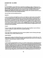
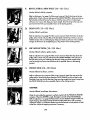
1.
BUTTERFLY (15-125
Lbs.)
J_usclesaF[ectacJ:
pedoral_s maior and m[nor, dellolcls
Re_ to adjustment 2 on Page 8 of thisownePs manual. Change the arms to the but"
tartly mode. Sit on t_ seat and hold the pods on the arms as shown;your arms
shouldbe bent at 90 ° angles. Keep your hock straight. Pressthe arms together until
the pods touch. Relum to the starting position.
2.
BENCH PRESS (30-250
Lbs.)
Musclesal_ctad: Pactaralismaiorand minor,anlerlordellolds,triceps
Referto adjustment 2 on page 8 of thisowner's manual. Change the arms to the
pressmode. Sit on the seat and hold the handles on the an'ns _th an over_nd grip.
Raiseyour elbowsas shown. Keep your back straight. Fully extend your arms. Return
to the starting pasition.
3.
FRONT ARM RAISE (15-125
Musclesa_ad:
Lbs.)
deltoids, rhomboids
Refer to adjustment4 on page 9 of this owner's manual. Attach the strap to the low
pulley station. Stand with one heel on the foot plata. Hold the strop with on overhand
grip with your arm at your side. Keep your back sll"alght.Raise the strap until your
hand is level with your shoulderas shown. Re_,m to the startingposition.
4.
UPRIGHT
ROW (15-125
Lbs.)
Muscles
oF&dad:
biceps,
deltalcls,
_pezius
Referto adjustment 4 on page 9 of this owner's manual. AJtochthe rower bar to the
low pulley station. Stand with your feet on the foot plata. Hold the rower bar with an
overhandgrip with your arms extended downward. Keep your back straight. Liftthe
rower bar until your hands ore levelwith your c_est as shown. Returnto the starting
position.
..
5.
SHOULDER SHRUG (15-125
Lbs.)
Muscles
oF_tacl:trapezlus,rhornbo;ds
Referto ad_uslment4 on page 9 of this owner's manual. Attach the rower bar to _-m
low Pulley station. Stand with your feet on the foot plata. Hold Iha rower bar with an
over_nd grip with your arms exl_nded downward. Keep your back straight and
your arms at your sides.Shrug your shouldersup as far as passible. Relum to the
startingposition.
17
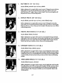
6.
LATERALARM
RAISE (15-125
Lbs.)
Musclesaffecfed:deltoids, tropezlus
ReFerto adjustment4 on page 9 of this owner's manual. Attach the shop to the low
pulley statlon. Sfand with your side toward the CROSS TRAINER • with your feet on
the foot plate. Hold the stropwith an overhand grip with your arm at your side. Keep
your back straight. Raise the stropto the side until your hand is level with your shoulder as shown. Returnto the starting position.
7.
SEATED ROW--CLOSE
GRIP (15-125
Muscles affected:deltolds/Irapezius,
Lbs.)
biceps, brachloradials, latlssimus dorsl
ReFerto adjustment4 on page 9 of this owner's manual Attach the rower bar to the
low pulley station. Sit on the floor with your heels on the foot plate, lean forward,
extend your arms and hold the rower bar with on overhand grip. Pull the rower bar
toward your stomachand lean back, keeping your elbows dose to your sides. Refum
to the staffingposition.
8.
LAT PULL-DOWN--CHEST
(15-125
Lbs.)
Muscles affecfed:Iotisslmus dorsl, trapezius, pectorolls maior
ReFerto adjustment3 on page 8 of this owner's manual. Attach the ]at bar to the
high pulley station. Sit on the seat facing the CROSS TRAINERe. Exfend your arms
upward and hold the lot bar with an overhand grip. Keep your back straight. Pull the
lot bar down until your hands are level with your neck as shown. Return to the storting position.
9.
LAT PULL-DOWN-BACK
(15-125
Lbs.)
Musclesa_,cted: Iotissimus dorsl, tropezlus
Refer to adjustment3 on page 8 of this owner's manuaJ.Attach the lot bar to the
high pulley stotbn. Sit on the seat facing the CROSS TRAINER e. Exfend your arms
upward and hold the lot bar with an overhand grip. Keep your back straight and
lean forward slightly. Pullthe lot bar down behindyour head until your hands are
level with your neck. Return to the stordng position.
10.
HIP EXTENSION
(15-125
Lbs.)
Musclesoffec'led:gluteusmaximus
ReFerto adjustment4 on page 9 oLrthis owner's manual. AHoch the sfrap to the low
pulley stotbn. Stand with one foot on the foot plate. Insedone leg into the strop.
Keep your back strolght. Keep your leg straight and move it backward as for as passibFe.Returnto the starting position.
18
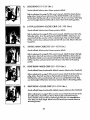
11.
LEG EXTENSION (15-125
Lbs.)
MusclesaF[eded: quadrlceps
Sit on the seat end position your feet under the pads on the leg developer. Keep your
back straight. Roisethe leg developer unfityour legs ore straight. ReturnIo the starting position.
12.
HIP ABDUCTION
(15-125
Lbs.)
Muscles
affec_d:abc/ucl_r,gluteusmedlus
Refer to adjustment 4 on page 9 of th;s owner's manual. Attach the strap to the low
pultey station. Stand with your side toward the CROSS TRAINER e with one foot on
the foot plate. In_ert your out_ide leg into the strap.Keep your back straight. Keep
your leg strolghtand move it ta the side as far as possible.Retam to the starting
position.
13.
BICEPS CURL (15-125
Lbs.)
Muscles ot_ecl: biceps, brochloradlals
Refer ta odjustrnent4 on page 9 of' this owner's manual. Affoch the rower bar to the
lowpulleystation.Standwith your feet on the foot plate. Hold the rower bar with an
underhond grip with your arms extended downGard. Keep your back straightand
your elbows close ta ),our sides. Cud the rower bar up taward your chestas shown.
Relum to the starting position.
14.
TRICEPS EXTENSION (15-125
Musclesa_ecl:
Lbs.)
triceps,brachloradlals
Refer to odiustment3 on page 8 of this owner's manual. Attach the rower bar to the
high pulley station. Sit on the seat, hold the rower bar obave your head and bend
your elbows. Keep your back straight and your elbows in. Slowly straightenyour
arms as shown. Relum to the starling position.
15.
TRICEPS PRESS-DOWN (15-125
Lbs.)
Musclesaffecfed: triceps, brachloracllals
ofthlsowner's manual. Attach the rower bar ta the
highpulleystation.StandwithyourfeetonthefootpIote.Holdtherowerbarwithon
Refer to adjustment3 on page 8
overband grip with your hands at chestkwel. Keep your back straight and your
elbows dose to your sides. Presslho rower bar down untilyour arms are strolght.
Relum to I_ startingposition.
19
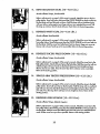
16.
SINGLE LEG CURL (15-125
Lbs.)
Musclesaffected:hamstring,gastrocnemlus
StandfacingtheCROSSTRAINER• and restthe backof one legagainstthe lower
pod onthelegdeveloper. Raisethelegdeveloperas far as passibleby bendingyour
legasshown.Returnto the startingposition.
17.
AB CRUNCH (15-125
Lbs.)
Muscles affected: reclusal_Jominus, upper abdornlnals
Referta adjustment
3 on Page 8 of thisowner'smanual.Attach theslrap to the high
pulleystation.Siton the seatand hold the strapbehindyourheadas shown.Keep
your backstraight.Slowlybend forwardat the waistuntilyourupperbody is at a
45* angle. Returntothe startingposition.
18.
BACK EXTENSION (15-125
Lbs.)
Musclesaffected:hipextensors
Referto adjustment
4 on Page 9 of this owner'smanual.Attachthelot bar to the low
pulley station.Siton thefloorwithyour heelson the footplate.Crossyour armsand
holdthelet bar againstyourchestasshown. Keepyourback slralght.Bendback at
the waist.Returnto thestartingposition.
19.
WRISTCURL
(15-125
Lbs.)
MusclesaEected:brachloradials
Referto adjuslment4 on page 9 of this owner'smanual.Altoch therowerbar to the
low pulleystation.Standwithyour feeton the footplate.Holdthe rowerbar withon
overhandgripwith yourarmsextendeddownward.Keepyourarmsstationaryand curlyourhandsup as far as passible.Returnto the starling position.
20.
TOE RAISE (15-125
Lbs.)
MusclesatTeded:gastrocnemius
Referto adjuslment4 on Page 9 of this owner'smanual.Attachthe rowerbar to the
low pulleystation.Stoadwithyour feeton the footplate. Holdthe rowerbar withon
overhandgrip with yourarmsexlendaddownward.Keepyourback strolghtand
yourarmsal yoursides.Riseupon yourtoesas foras possible.Returnto the starting
Pasltion.
2O
A.
SIDE BEND (15-125
Lbs.)
Musclesaffected:laEsslmusdorsl, biceps, posterior deltoids
Referto adjustment4 on page 9 of this owner's manual. Attach the strap to the low
pulley station.Standwith your side toward the CROSS TRAINER e with one foot on
the foot plate. Hold the strapwith an overhand grip with your arm at your side. Keep
your back straight.Bendtoward the side as shown. Returnto the starting position.
B.
LATPULL-DOWN--CLOSE
GRIP (15-125
Lbs.)
Musclesaffe_ed: latissimus dorsl, biceps, posterior deltoids
Referli adjustment3 on page 8 of this owner's manual. Attach the rower bar li the
high pulley station.Sit on the seat facing the CROSS TRAINERe. Extendyour arms
upward and hold the rower bar with an underhand grip. Keep your back straight.
Pullthe rower bar clownuntilyour hands are level with your neck. Returnli the slirt"
ing position.
C,_
SINGLE ARM CABLE FLY (15-125
Lbs.)
Muscles affected:laEssimusdorsi, biceps, posterior deltoids
Referli adjustment3 on page 8 of this owner's manual. Aflach the strap to the high
pulley station.Stand with your side toward the CROSS TRAINERe with one foot on
the foot plate. Extendone arm upward and bald the sh:ap.Keep your back straight.
Pullthe strapdown until your hand is level with your waist. Returnto the starting
position.
D.
BENT ROW-WIDE
Muscles
a_'.
GRIP (15-125
Lbs.)
biceps,brachloradials,
deltoids,
Irapez;us,latisslmusdorsl,rl_ids
Referli adjustment
4 on page9 of thisowner'smanual.Atlich thetatbar li the low
pulleyslit[on.Standwithyourfeeton thefootplateand bendforwardas shown.
Holdthe latbar withan overhandgrip withyour armsexlendeddownward.Keep
yourbackstraight.Pullthela! bar towardyour slimach. Relumto thestartingposition.
E.
BENT ROW-CLOSE
GRIP (15-125
Lbs.)
Musclesaffeded: biceps,brachloradials,deltoids,trapezius,la_ssimusdorsl,rhomboids
Referto adjustment4 on page 9 of this owner's manual. Attach the rower bar to the
low pulley station.Stand with your feet on the foot plate and bend _,vard as
shown.Hold the rower bar with an overhand grip with your arms exJendeddownward. Keepyour back straight. Pullthe rower bar toward your stomach.Returnto
the startingposition.
21
F.
SINGLE ARM BENT ROW (15--125
Lbs.)
MusclesaA_c'led:biceps,brachiaredials, deltoids,Irapezius, lah'ssimusdorsi, rhombo;ds
Refer to adjustment 4 on page 9 of this owner's manual. A_ach the strap to the low
pulley station. Stand with your feet on the foot plate and bend forward as shown.
Hold the strap with an overhand grip with your arm extended downward. Keep your
back straight. Pullthe strap toward your stomach. Returnto the starting position.
G.
SEATED ROW--WIDE
GRIP (15-125
Lbs.)
Musclesaffected: deltoids, trapezius, biceps, brachioradials, latissirnus dorsi
Refer to adjustment4 on page 9 of this owner's manual. Attach the fat bar to the low
pulley station. Sit on the floor with your heelson the foot plate. Lean forward, extend
your arms and hold the lat bar with an overhand grip. Pullthe lot bar toward your
stomachand lean back. Returnto the starting position.
H.
SINGLEARM
SEATED ROW(15--125
Lbs.)
Musdes
aEecled:
biceps,
brc_hioradlals,
deltoids,
tropez,'us,
_'ssimusdo.i. rhomboids
_.R.e_r to adjustment4 on page 9 of this owner's manual. Attach the slrap to the low
pulley station. Sit on the floor with your heels on the foot plate. Lean forward, extend
one arm and hold the strap. Pullthe strap toward your stomachand lean back, keeping your elbow close to your side. Return to the startingposition.
_i
Ii
'_ •
REVERSE BICEPS CURL (15--125
Lbs.)
Musclesaffected:biceps,brachioradials
Refer to adjustment,4 on page 9 of this owner's manual. Attach the rowel"bar to the
low pulley station. Stand with your heels on the foot plate. Hold the rower bar with
a n overhand grlp with your arms extended downward. Keep your back straight and
your elbowsclose to your sides.Curl the rower bar up toward your chest as shown.
Return to the starting position.
Jo
ISOLATION CURL (15--125
Lbs.)
Musclesaffected: biceps, brachloradials
Refer to ad[uslment,4on page 9 of this owner's manual. Attach the strap to the low
pulley station. Stand with your side toward the CROSS TRAINER e with one foot on
foot p/ate. Hold the strap with an underhand grip with your arm extended down:
ward. Pullthe strap up until your hand is level with your chest. ReturnIo the starting
position.
22
K.
BENT ISOLATION
CURL (15--125
Lbs.)
MusclesatTectecl:
biceps,brachloradlals
Refer ta adjustment4 on Page 9 of this owner's manuQI. ,6,ffoch_ stropto the low
pulley station. Stand with your side _.ward the CROSS TRAINER e, place one foot on
the foot plate and bend forward as shown. Hold the stropwith on underhand grip
with your elbow restingagainst your kneeand your arm extended downward. Pull
the strap up until your hand is level with your chest. Returnto the storffng position.
L.
REVERSE WRIST CURL (15-125
Lbs.)
Muscles
aFfecled:
brachloradlols
Refertoadjustment4 on page 9 of thisowner'smanual.Attachthe rowerbar to the
k_v pulleystollon.Stand facing awayfromthe CROSSTRAINERe withyour heels€_n
the footplate.Hold the rowerbar behindyourbackasshown.Keepyour armsstationaryand curlyourhandsupasfar aspossible.Relurnto the starting position.
Mo
REVERSETRICEPS PRESS-DOWN (15--125
Lbs.)
Musclesaffected:triceps,brachloradials
Refer to adjustment 3 on page 8 oFthis owner's manual. AI_Ch the rower bar to the
hlgh pulley station. Stand with your feet on the Tootplate. Hold the rower bar with an
.i
underhand grip with your hands at chestlevel. Keep your back straight and your
elbows close to your sides. Pressthe rower bar down untilyour arms are straight.
Returnto the startingposition.
N.
SINGLE ARM TRICEPS PRESS-DOWN (15--125
Lbs.)
Musclesaffected:triceps,brachlomdlals
Refer to adjustment 3 on page 8 of thls owner's manual. Attach the strap to the high
pulley station. Stand with your feet on the foot pfate. Hold the strap with on overhand
° grip with your hand ot chesl level. Keep your back straight and your elbow close to
your side. Pressthe strap down untilyour arm is straight as shown. Reh_mto the
stortlngposition.
O.
REVERSE UPRIGHT
ROW (15--125
Lbs.)
Muscles
affected:
biceps,deltolds,
_pezlus
Referto adjustment4 on Page9 of thisowner'smanual.Attachtherowerbar to the
lowpulley station.StandfacingawayfromtheCROSSTRAINER• withyourheelson
thefootplate.Holdtherowerbar behindyourback with yourarmsextendeddownword. Lifttherowerbar upasfar aspossible.Retumto the starting position.
23
P.
BENT LATERAL ARM RAISE(15-125
Lbs.)
Musclesaffected:deltoids,trapezius
Refer ta adjustment4 on page 9 of this owner's manual. Attach the strap to the low
pulley station. Stand with your side toward the CROSS TRAINER e, place one foot on
the foot plate and bend forward as shown. Hold the strap with an overhand grip
with your arm at your side. Keep your back straight. Raise the strap to the side until
your hand is level with your shoulder. Return to the starting position.
Q.
DEAD LIFT (15-125
Lbs.)
Muscles af[ected: quadriceps
Refer to adjustment4 on Page 9 of this owner!s manual. Attach the lat bar to the low
pulley station. Stand with your feet on the foot plate and bend your knees as shown.
Hold the lat bar with an overhand grip. Keep your head up and your arms and back
straight.Lift the lat bar by straighteningyour legs. Return to the starting position.
R.
HIPADDUCTION
(15-125
Lbs.)
Muscles affected:adductor, gluteusmedlus
Refer to adjustment4 on Page 9 of this owner's manual. Attach the strap to the low
pulley station.Stand with your side toward the CROSS TRAINER e with one foot on
the foot plate. Insertyour inside leg into the strap. Keep your back straight. Keep
your leg straightand move it to the side as Faras Passible. Returnto the starting
position.
Sm
FRONT KICK (15-125
Lbs.)
Musclesaffeded: hip flexors, sartorius
Refer to adjustment4 on Page 9 of this owner's manual. Attach the strap ta the low
pulley station. Stand facing away from the CROSS TRAINER • with one heel on the
foot plate. Insertone leg into the strap. Keep your leg straightand move it away from
the CROSS TRAINER e as for as Passible. Returnto the starting position.
STEPPER
MusclesAffe_ed: quadHceps, hip extensors
(Note: Do not include thisexercise in workoutscreated with the PERSONALTRAINER
computer.When the STEPPERis used, the stepper consolewill provide feedback.)
Referta adjustment1 on page 8 of this owner's manual. Hold the stepperhandle and
begin stepping,alternately pressingthe left and right pedals down with a smooth,
continuousmation.-a continuousmotion mustbe maintained or both pedals will sink
to the floor. Adjust the stepping resistanceif necessary.
24
TROUBLE-SHOOTING
AND
MAINTENANCE
Inspectand tighlenall parts each time you usethe CROSS TRAINERe. Replace any warn parts immediately. Outside
surfacesof the CROSS TRAINERe can be cleaned using a damp clothand mild detergent. Keep all liquids away from
the stepperconsole and the PERSONALTRAINER computer. Most CROSSTRAINER• problems can be solvedby following the slaps below. Find the applicable symptom and fallow the slap(s)lided. If further assistanceis needed, call our
Customer ServiceDepadment toll-free at 1-800-999-3756,
Monday throughFriday, 6 a.m. until'6 p.m. Mountain
.time (excluding holidays).
1. SYMPTOM: THE PERSONALTRAINER COMPUTER DISPLAYS AN ERROR CODE ("EEE")
a. While theweightsettingischanging, the motor willbeheard
andtheSETS
andREPSdisplayswillshowa rapidly
rotatingindicator. To preventdamage to the weight system,do not put any pressureon the leg developer,arms
or cableswhile the weight settingischanging. Ifthe tat bar or rower bar is attached to the high pulley station,restit
in the rock near the high pulleystation.Wait for.the soundof the motorto stop before you continue. If the computer sensespressure on the weight systemwhile the weight settingischanging, the WEIGHT display will show an
• error code ("EEE")for two seconds,and the weight settingwill sl-opchanging. The WEIGHT dis'pla),will then show
the current weight setting.Make sure that there is no pressureon the leg developer, arms or cables. Pressthe
increaseor decrease button beneath the WEIGHT display to changethe weight settingas desired.
2. SYMPTOM: THE MAIN CABLE DOES NOT MOVE SMOOTHLY, OR THERE IS SLACK IN THE MAIN CABLE
a. Inspectthe routingof thecables and make sure that they are in the grooves in all of the pulleys.If they are not,
tarred the problem. If the cables are not properly routed, they will be damaged when used..
b. If there is slackin the Main Cable (51), locate the
AdjustmentBracket(53) near the bottom of the
....
right side shield.Hold the end of the Weight Cable
(52) firmly, and slidethe Adjustment Bracket farther ontothe Weight Cable. Tighten the 5/16" Nut
(82) ogaiest the AdjustmentBracket. Testthe Main
Cable. If the mator stallsor hesitates,loosen the
5/16" Nut slightly.If the 5/16" Nut is tightened as
far as passible and there is still slack, the Main
Cable shouldbe replaced. See ORDERING
REPLACEMENTPARTSon the back cover of this
ownerls
51
monuok
3.- SYMPTOM:THE STEPPERCONSOLE DOES NOT
FUNCTION PROPERLY
99
a, As you step, movethe stepper pedals vertically at
least 8 inches.If)our stepsare too shallow, the
movementof the stepperpedals will not be detected. If the stepperconsolestilldoes not function
/
120
IE
properly, the Reed Switch(99) con be adjusted by
sliding the barrel of the ReedSwitch up and down
slightly. Repeatuntil the stepperconsole displays
correctfeedback. If necessary,the 3/4" Screw
(119} attaching the Reed Switch Bracket(120) can
\
\
_ounting
I
be loosenedand the positionof the Bracket can be
adjusted.
25
119/
eeye
b.
If the LCD display becomes dim, the 1.5-volt watch
batteries in the Stepper Console (88) should be
replaced. Using a shortphillips screwdriver,
remove the two screws attaching the back of the
Stepper Console. Using the screwdriver,carefully
push the two ba_ries out of the barry d;ps; be
careful to note which way the batteries ore turned.
Insert two new 1.5-yah watch batteries into the
1.5-Volt
Watch
Batteries
battery clips. Reat/achthe back of the Stepper
Console.
4.
SYMPTOM: THE POWER DOES NOTTURN ON
a.
5.
Make sure that the transformeris fullyplugged into the jack on the CROSS TRAINERe, and into a 12a-volt outlet.
SYMPTOM: THERE IS A CLICKING SOUND WHEN USING THE ARMS
a,
Tigh_ theindica_d3/8" Nylock
Nut(61further
onto the 3/8" x 3 1/2" Bah (42) on each Arm
(15, 16) until the Swivel Brackels(141 do not slide
back and forth on the Balls. Becareful not to overtighten the Nylack Nuls; the SwivelBracketsmust
be able to swivel easily.
© 1994 Sears, Roebuckand Co.
26
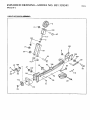
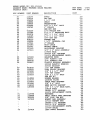
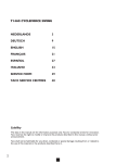
EXPLODED DRAWING--MODEL
NO. 831.159341
R694A
PAGE2 OF 2
WEIGHT MECHANISM A'gSE'/I_B'L_-
105
100
6
105
93
109
115
69 106
95
,
90
108
95
107
32
Z
113
94
114
92
71
112
111
95
•
E..X..pl
nn,-,-, DRAWiNG-MODEL
w-
NO. 831.159341
R694A
I0
16
97
6/
1:
77
94
119
o
98
19".,
46
28
76
27
118
23
40
5
--16
13
51
13
7
48
15
42
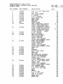
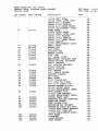
SEARS MODEL NO: 831.159341
PRODUCT
NAME: PROFORM CROSS
PRODUCT
DESC:
KEY
NUMBER
PART
NUMBER
1
2
3
4
5
6
7
8
9
l0
ii
112003
112004
112006
117737
115370
012149
117120
116746
116742
NSP
119583
i2
119584
13
14
15
106480
117732
117908
16
i17909
17
18
19
2O
21
22
23
i14797
112560
i17104
013468
114798
108726
117910
24
116913
_5
26
27
28
29
3O
31
32
33
34
103903
109989
103833
117099
116149
108874
117332
106879
115383
107281
TRAINER
RUN
RUN
DESCRIPTION
COST
3/8" X 2 1/2" CARR BOLT
3/8" NUT
3/8" LOCK WASHER
2" PULLEY
3 1/2" PULLEY
3/8" NYLOCK NUT
FRONT BASE
REAR BASE
UPRIGHT
TOWER FRAME
LEFT SIDESHIELD
W/DECAL
118187 LEFT SIDESHIELD
115553 SIDESHIELD
DECAL
RIGHT SIDESHIELD
W/DECAL
118186 RIGHT SIDESHIELD
115553 SIDESHIELD
DECAL
117508 DO NOT... DECAL
2 3/4" PULLEY
SWIVEL BRACKET
LEFT ARM ASSEMBLY
117126 LEFT ARM
109989 BUSHING
103735 3/4" AXLECAP
111374 REPLACEMENT
INSTR.
RIGHT ARM ASSEMBLY
117124 RIGHT ARM
109989 BUSHING
103735 3/4" AXLECAP
111374 REPLACEMENT
INSTR.
LARGE PAD
GRIP
BACKREST
1/4" X 5/8" BOLT
SMALL PAD
PAD TUBE
LEG DEVELOPER
ASSEMBLY
117130 LEG DEVELOPER
103903 1/2" AXLECAP
117498 DECAL
111374 REPLACEMENT
INSTR.
1/2" X 2 i/2" AXLE ASSY.
100051 AXLE
103903 1/2" AXLECAP
111374 REPLACEMENT
INSTR.
1/2" PLASTIC CAP
3/4" BRASS BUSHING
1 i/2" X 1 1/2" CAP
SEAT
BRACE
2" X 2" CAP
3/8" X 3/4" BOLT
3/8" X 3" BOLT
CABLE CLIP
ROWER BAR
DATE:
TIME:
.oo
.oo
.oo
.oo
.oo
.oo
.oo
.oo
.oo
.oo
14.17
.oo
.oo
.00
16 51
oo
oo
oo
oo
oo
• oo
oo
oo
.oo
.oo
.oo
.oo
.oo
.oo
.oo
.oo
.oo
.oo
.oo
.oo
.oo
.oo
.00
.oo
.oo
.oo
.oo
.oo
.oo
.oo
.oo
.oo
.oo
.oo
.oo
.oo
.oo
.oo
.oo
7/07/
11:46:
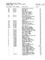
SEARS MODEL NO: 831.159341
PRODUCT
NAME: PROFORM CROSS
PRODUCT
DESC:
KEY
NUMBER
35
36
37
38
39
4O
41
PART
NUMBER
115177
115115
106526
118004
109954
013399
115762
42
43
44
45
46
_7
48
49
50
51
52
53
54
612139
117106
013578
116185
105496
019115
115998
117541
117386
117741
117260
117913
55
56
57
58
i17489
100151
103735
109867
9
60
61
62
63
64
65
013162
116181
115260
013522
116215
66
117127
67
68
69
70
115257
013430
116065
120446
71
72
73
74
i13795
116630
105133
117915
75
i17916
114958
TRAINER
RUN
RUN
DESCRIPTION
COST
STRAP
LAT BAR
1 1/4" CAP
CHAIN
TRANSFORMER
3/8" X 1 3/4" BOLT
l" PULLEY
SEE KEY #68
1/4" NYLOCK NUT
1/4" X i" SHOULDER
BOLT
3/8" X 2 1/4" BOLT
1/4" X 2 1/2" BOLT
3/8" NAT CAP
RUBBER PAD
1 1/2" INTERNAL
CAP
2" ROLLER
MAIN CABLE
WEIGHT CABLE
ADJUSTMENT
BRACKET
3/4" X 4" AXLE ASSEMBLY
114656 AXLE
103735 3/4" AXLECAP
111374 REPLACEMENT
INSTR.
SELECTOR KNOB
5/8" PLASTIC CAP
3/4" PLASTIC CAP
PLASTIC BUSHING
ASSEMBLY
100048 PLASTIC
BUSHING
103735 AXLECAP
1/2" PAN SCREW
LONG PULLEY BRACKET
3/8" X 6 1/2" BOLT
3/4" TAP SCREW
3/8" X 1 1/2" BOLT
SEE KEY #2
RUBBER WASHER
LOCKING PLATE
CABLE TRAP BRACKET
3/8" X 4" BOLT
REED SWITCH BRACKET
1/2" X 4 1/2" AXLE ASSY.
118118 AXLE
103903 1/2" AXLECAP
111374 REPLACEMENT
INSTR.
FASTENER
SMALL CABLE TRAP BRACKET
3/8" ZINC JAM NUT
MOMENT ARM ASSEMBLY
117122 MOMENT ARM
103903 1/2" AXLECAP
103735 3/4" AXLECAP
111374 REPLACEMENT
INSTR.
117499 DECAL
LEFT PEDAL ASSEMBLY
DATE:
TIME:
oo
oo
oo
oo
oo
oo
oo
.oo
.oo
.oo
.oo
.oo
.oo
.oo
.oo
.oo
.oo
.oo
.oo
.oo
.oo
.oo
.oo
.oo
.oo
.oo
.oo
.oo
.oo
.oo
.oo
.oo
.oo
.oo
.oo
.oo
.oo
.oo
.oo
.oo
.oo
.oo
.oo
.oo
.oo
.oo
.oo
.oo
.oo
.oo
.oo
.oo
.oo
.oo
7/07/9
11:46:4
SEARS MODEL NO: 831.159341
PRODUCT NAME: PROFORM
CROSS
PRODUCT DESC:
TRAINER
RUN
RUN
KEY
DESCRIPTION
COST
NUMBER
PART
NUMBER
76
117917
77
78
79
80
81
82
83
84
107148
012135
116109
116048
113349
012003
105101
109398
85
109872
86
87
88
89
90
91
92
93
94
116120
101149
115126
105136
105142
012082
013510
115100
117920
95
117921
96
97
98
99
i00
101
115199
117298
117323
117903
117305
i17914
i02
103
104
105
117037
117262
i17881
104345
117116 LEFT PEDAL
107148 PEDAL COVER ASSY
103735 3/4" AXLECAP
100048 PIVOT BUSHING
105101 3/4" METAL COVER
111374 REPLACEMENT
INSTR.
RIGHT PEDAL
117114 RIGHT PEDAL
107148 PEDAL COVER ASSY
103735 3/4" AXLECAP
100048 PIVOT BUSHING
105101 3/4" METAL COVER
113349 MAGNET
111374 REPLACEMENT
INSTR.
PEDAL COVER
NYLOCK NUT
7/8" SCREW
ACTUATOR
ARM
MAGNET SLEEVE
5/16" NUT
3/4" METAL COVER
RESISTANCE
CYLINDER
ASSY.
109398 RESIST. CYLINDER
100151 AXLECAP
5/8" BUSHING ASSEMBLY
109399 BUSHING
100151 AXLECAP
5/8" SPACER
3/8" FENDER WASHER
STEPPER CONSOLE
GAS SHOCK
BALL JOINT
5/16" NYLOCK NUT
3/4" SELF-TAP
SCREW
3/8" X 4" CLEVIS PIN
WEIGHT MECHANISM
W/RI
117301 WEIGHT MECH
117884 REPLACEMENT
INSTR.
WIRE HARNESS W/RI
117141 WIRE HARNESS
117885 REPLACEMENT
INSTR.
CUSTOM SMART CARD
PERSONAL
TRAINER COMPUTER
EXERCISE
INSERT
REED SWITCH WIRE
MECHANISM
ADJ BRACKET
MECHANISM
CABLE BKT ASSY.
114634 MECH CABLE BRACKET
105496 3/8" PUSH NUT
111374 REPLACEMENT
INSTR.
FOOT PLATE
U-BRACKET
CABLE BRACKET
STAR WASHER
DATE:
TIME:
.o0
.oo
.oo
.0o
.00
.o0
.o0
.o0
.00
.00
.00
.oo
.oo
.oo
.o0
.oo
.00
.o0
.o0
.oo
.o0
.o0
.00
.o0
.0o
.o0
.00
.oo
.0o
.00
.00
O0
oo
oo
O0
O0
O0
.00
.oo
.oo
.00
.00
.00
.0o
.0o
.o0
.00
.o0
.00
.00
.0o
.0o
.00
.00
7/07/94
II:46:4L
SEARS MODEL NO: 831.159341
PRODUCT
NAME: PROFORM
CROSS
PRODUCT
DESC:
TRAINER
RUN
RUN
KEY
DESCRIPTION
COST
NUMBER
PART
NUMBER
DATE:
TIME:
.........................
106
107
108
109
ii0
115124
014153
109568
116049
117905
ill
112
i05122
115131
113
114
115
116
ll7
118
119
120
121
616029
115110
019266
117738
110943
013498
013300
117900
117701
B
C
D
E
F
G
H
I
J
K
L
M
N
O
P
Q
R
S
033134
106739
lll000
i06718
014132
106832
I16571
117322
107622
117508
115553
117538
113764
117499
117498
117837
111465
119391
119390
119436
117158
MECHANISM
REED
SWITCH
FLAT WASHER
SLIDE NUT
RETAINER
CUP
LEAD SCREW
ASSEMBLY
108979
LEAD SCREW
106740
5/8" PUSH NUT
105119
5/16"
CLIP
5/16"
PUSH NUT
MECHANISM
MOTOR
ASSEMBLY
115123
MECH MOTOR
115110
ENCODER
DISK
115124
REED
SWITCH
WIRE
105884
TAPE
WIRE TIE
MECHANISM
ENCODER
DISK
NYLON
SPACER
SIDESHIELD
FASTENER
3/8" X 2 3/4" CARR
BOLT
1/4" X 2" BOLT
3/4" SCREW
REED SWITCH
BRACKET
REED SWITCH
FASTENER
NON-ILLUSTRATED
PARTS
STEPPER
CONSOLE
BATTERY
STEPPER
CONSOLE
CVR SCREW
1/2" BRASS
BOSHING
SMALL
CABLE
TRAP
3/8" FLAT WASHER
FLAT NYLON
WASHER
3/4" ENDCAP
CUSTOM
EXERCISE
DECAL
SHT
WARNING
DECAL
WARNING
DECAL
SIDESHIELD
DECAL
L/R PEDAL
DECAL
SET
HOT DO NOT TOUCH
DECAL
MOMENT
ARM DECAL
LEG EXTENSION
DECAL
VIDEO
FITNESS
JOURNAL
PART LIST/EXP
DRAWING
OWNER'S
MANUAL
LITERATURE
PACKET
119390
OWNER'S
MANUAL
i19391
PART LIST/DWG
115199
CUSTOM
SMART
CARD
116186
SMART
CARD LIT
111465
FITNESS
JOURNAL
117837
VIDEO
117323
CUSTOM
OVERLAY
117322
CUSTOM
EX. DECAL
HARDWARE KIT,PARTS BOX
112560
GRIP
.oo
.oo
.oo
.o0
.oo
.oo
.00
.0o
.oo
.00
.oo
.oo
O0
oo
OO
O0
O0
oo
oo
O0
oo
.o0
.oo
.oo
.00
.oo
.o0
.oo
.00
.oo
.oo
.00
.oo
.00
.00
.00
.oo
.0o
.oo
.o0
.00
.22
1.73
10.93
.00
.00
.00
.00
.00
.00
.00
.00
.00
.00
7/07/9_
ii:46:4_
SEARS MODEL NO: 831.159341
PRODUCT
NAME: PROFORM
CROSS
PRODUCT
DESC:
TRAINER
RUN
RUN
KEY
DESCRIPTION
COST
NUMBER
PART
NUMBER
DATE:
TIME:
..................................................
118468
117126 LEFT ARM
i17124 RIGHT ARM
117732 SWIVEL BRACKET
116149 STEPPER BRACE
107281 ROWER BAR
115115 LAT BAR
013430 3/8" X 4" SCREW
012149 3/8" NYLOCK NUT
114797 LARGE FOAM PAD
114798 SMALL FOAM PAD
117099 SEAT
117037 FOOT PLATE
108726 PAD TuBE
116571 3/4" INT ENDCAP
117104 BACKREST
109954 POWER CORD
106526 ENDCAP
HARDWARE
KIT,BLISTERPAK
112003 2.5" CARRIAGE
BOLT
I18004 CHAIN
I15383 SNAP HOOK
112004 3/8" HEX NUT
012003 5/16" HEX NUT
115177 ANKLE STRAP
112006 LOCK WASHER
117332 3/8"X.75"
BOLT
013468 I/4"X5/8"
BOLT
013498 I/4"X2" BOLT
013399 3/8"XI.75"
BOLT
115370 PULLEY
106480 PULLEY
117737 PULLEY
115257 BRACKET
019115 BUMPON
114656 AXLE
103735 3/4" AXLECAP
013578 3/8"X2.25"
BOLT
116185 I/4"X2.5"
BOLT
012149 3/8" HEX NUT
117738 FASTENER
.oo
.oo
.oo
.oo
.oo
.oo
.oo
.oo
.oo
.oo
.oo
.oo
.oo
.oo
.oo
.oo
.oo
19 .16
.oo
.oo
.oo
.oo
.oo
.oo
.oo
.oo
.oo
.oo
.oo
,oo
.oo
.oo
.oo
.oo
.oo
.oo
.oo
.oo
.oo
.oo
7/07/9
11:46:4
ORDERING
REPLACEMENT PARTS
Each CROSS TRAINER e has itsown MODEL NUMBER. Ab_::ys mention this MODEL NUMBER when requesting service
or repair paris for your CROSS TRAINER e.
All parts llsted herein can be ordered through SEARS, ROEBUCKAND CO. SERVICECENTERSand most SEARS
RETAILSTORES.If parts you need are not stockedlocally,your order will be transmitted to a SEARS PARTSDISTRIBUTION CENTERfor handling.
WHEN ORDERING REPAIRPARTS,ALWAYS GIVE THE FOLLOWING INFORMA11ON:
1. The MODEL NUMBER af the product (831.159341 ).
2. The NAME of the product (PREFORM* CROSSTRAINER e).
3. The PARTNUMBER of the part(s) from the PARTUST/EXPLODEDDRAWING accompanying this Owner's manual.
4. The DESCRIPTIONof the part(s) from the PARTUST/EXPLODEDDRAWING accompanying this owner's manual.
Your SEARSmerchandise has added value when you consider that SEARShas service units nationwide, staffedwith
SEARStrained technicians specifically trained on SEARSpreduds, having the parts, toolsand equipment to ensure that
we meet our pledge to you: 'We service what we sell.'
Should you ever need repair service or paris, call toll-free: .
For repair service: 1-800-4-REPAIR (1-800-473-7247)
For repair parts: 1-80a-FaN-PART (1-800-366-7278)
t
FULL 90 DAY WARRANTY
For90 claysfrom the date of purchase, when proper assemblyand maintenance procedures detailed in the
owner's manual are followed, SEARSwill, free of charge, repair or replace and installa replacement part for
any defectivepart, when the PREFORM* CROSSTRAINER e is used in a normal manner.
This worranly does not apply when the CROSSTRAINER • ;s used for commercial or renlal purposes.
SERVICEIS AVAILABLESIMPLYBY CONTACTING YOUR NEARESTSEARSSERVICECENTER/DEPARTMENTIN
THE UNITED STATES.
Th;swarranty gives you specificlegal r;ghts;you may also have other rightswhich vary from state to state.
SEARS,ROEBUCKAND CO., DEPT.817WA,
3333 BEVERLYROAD, HOFFMAN ESTATES,IL 60179
Part No. 119390 R694A
Printed in USA