1
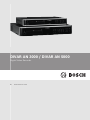
DIVAR AN 3000 / DIVAR AN 5000
Digital Video Recorder
en
Quick Reference Guide
DIVAR AN 3000 / DIVAR AN 5000
Table of Contents | en
3
Table of contents
1
Basic Safety
4
1.1
Safety precautions
4
1.2
Important safety instructions
4
1.3
Important Notices
6
1.4
FCC and UL
8
2
System overview
3
Quick install
10
3.1
Connections
10
3.1.1
Primary connections
12
3.1.2
Optional connections
12
3.2
Powering up
13
3.3
Login
14
3.4
Startup Wizard
15
3.4.1
Reset startup wizard
16
3.4.2
General
16
3.4.3
Encoder
17
3.4.4
Schedule
18
3.4.5
Record
18
3.4.6
Network
19
3.5
Shutdown/Logout
20
4
First time operation
21
4.1
Live viewing
21
4.2
Quick menu
24
4.3
Mouse controls
25
4.4
Main menu
27
4.5
Search/Playback
28
5
Maintenance
34
5.1
Attach ESD strap
37
5.2
Replace internal battery
37
5.3
Install HDD in DIVAR 3000
38
5.4
Install HDD in DIVAR 5000
41
5.5
Install DVD in DIVAR 3000
45
5.6
Install DVD in DIVAR 5000
47
Bosch Security Systems
9
Quick Reference Guide
2013.11 | 1.1 | AM18-Q0668
4
en | Basic Safety
1
DIVAR AN 3000 / DIVAR AN 5000
Basic Safety
This safety section describes safety requirements and the format used for warnings and
cautions.
1.1
Safety precautions
Warnings and caution formats
Danger!
High risk: This symbol indicates an imminently hazardous situation such as "Dangerous
Voltage" inside the product.
If not avoided, this will result in an electrical shock, serious bodily injury, or death.
Warning!
!
Medium risk: Indicates a potentially hazardous situation.
If not avoided, this could result in minor or moderate bodily injury.
Caution!
!
Low risk: Indicates a potentially hazardous situation.
if not avoided, this could result in property damage or risk of damage to the unit.
Notice!
This symbol indicates information or a company policy that relates directly or indirectly to the
safety of personnel or protection of property.
1.2
Important safety instructions
Read, follow, and retain for future reference all of the following safety instructions. Heed all
warnings on the unit and in the operating instructions before operating the unit.
1.
Cleaning - Unplug the unit from the outlet before cleaning. Follow any instructions
provided with the unit. Generally, using a dry cloth for cleaning is sufficient but a moist,
fluff-free cloth or leather shammy may also be used. Do not use liquid cleaners or aerosol
cleaners.
2.
Heat Sources - Do not install the unit near any heat sources such as radiators, heaters,
stoves, or other equipment (including amplifiers) that produce heat.
3.
Ventilation - Any openings in the unit enclosure are provided for ventilation to prevent
overheating and ensure reliable operation. Do not block or cover these openings. Do not
place the unit in an enclosure unless proper ventilation is provided, or the manufacturer's
instructions have been adhered to.
4.
Water - Do not use this unit near water, for example near a bathtub, washbowl, sink,
laundry basket, in a damp or wet basement, near a swimming pool, in an outdoor
installation, or in any area classified as a wet location. To reduce the risk of fire or
electrical shock, do not expose this unit to rain or moisture.
5.
Object and liquid entry - Never push objects of any kind into this unit through openings
as they may touch dangerous voltage points or short-out parts that could result in a fire
or electrical shock. Never spill liquid of any kind on the unit. Do not place objects filled
with liquids, such as vases or cups, on the unit.
2013.11 | 1.1 | AM18-Q0668
Quick Reference Guide
Bosch Security Systems
Basic Safety | en
DIVAR AN 3000 / DIVAR AN 5000
6.
5
Lightning - For added protection during a lightning storm, or when leaving this unit
unattended and unused for long periods, unplug the unit from the wall outlet and
disconnect the cable system. This will prevent damage to the unit from lightning and
power line surges.
7.
Controls adjustment - Adjust only those controls specified in the operating instructions.
Improper adjustment of other controls may cause damage to the unit. Use of controls or
adjustments, or performance of procedures other than those specified, may result in
hazardous radiation exposure.
8.
Overloading - Do not overload outlets and extension cords. This can cause fire or
electrical shock.
9.
Power supply cord and plug protection - Power supply cords should be routed so that
they are not likely to be walked on or pinched by items placed upon or against them,
playing particular attention to cords and plugs, convenience receptacles, and the point
where they exit from the appliance.
10. Power disconnect - Units have power supplied to the unit whenever the power cord is
inserted into the power source. The power cord plug is the main power disconnect device
for switching off the voltage for the unit.
11. Power sources - Operate the unit only from the type of power source indicated on the
label. Before proceeding, be sure to disconnect the power from the cable to be installed
into the unit.
12. Servicing - Do not attempt to service this unit yourself. Opening or removing covers may
expose you to dangerous voltage or other hazards. Refer all servicing to qualified service
personnel.
13. Damage requiring service - Unplug the power unit from the main AC power source and
refer servicing to qualified service personnel when any damage to the equipment has
occurred, such as:
–
the power supply cord or plug is damaged;
–
exposure to moisture, water, and/or inclement weather (rain, snow, etc.);
–
liquid has been spilled in or on the equipment;
–
an object has fallen into the unit;
–
unit has been dropped or the unit cabinet is damaged;
–
unit exhibits a distinct change in performance;
–
unit does not operate normally when the user correctly follows the operating
instructions.
14. Replacement parts - Be sure the service technician uses replacement parts specified by
the manufacturer, or that have the same characteristics as the original parts.
Unauthorized substitutions could void the warranty and cause fire, electrical shock, or
other hazards.
15. Safety check - Safety checks should be performed upon completion of service or repairs
to the unit to ensure proper operating condition.
16. Installation - Install in accordance with the manufacturer's instructions and in accordance
with applicable local codes.
17. Attachments, changes or modifications - Only use attachments/accessories specified by
the manufacturer. Any change or modification of the equipment, not expressly approved
by Bosch, could void the warranty or, in the case of an authorization agreement, authority
to operate the equipment.
Bosch Security Systems
Quick Reference Guide
2013.11 | 1.1 | AM18-Q0668
6
en | Basic Safety
1.3
DIVAR AN 3000 / DIVAR AN 5000
Important Notices
Accessories - Do not place this unit on an unstable stand, tripod, bracket, or mount. The
unit may fall, causing serious injury and/or serious damage to the unit. Use only with the
cart, stand, tripod, bracket, or table specified by the manufacturer. When a cart is used, use
caution and care when moving the cart/apparatus combination to avoid injury from tip-over.
Quick stops, excessive force, or uneven surfaces may cause the cart/unit combination to
overturn. Mount the unit per the manufacturer's instructions.
All-pole power switch - Incorporate an all-pole power switch, with a contact separation of at
least 3 mm in each pole, into the electrical installation of the building. If it is needed to open
the housing for servicing and/or other activities, use this all-pole switch as the main
disconnect device for switching off the voltage to the unit.
Battery replacement - For qualified service personnel only - A lithium battery is located
inside the unit enclosure. To avoid danger of explosion, replace the battery as per
instructions. Replace only with the same or equivalent type recommended by the
manufacturer. Dispose of the replaced battery in an environmentally friendly way and not with
other solid waste. Refer all servicing to qualified service personnel.
Notice!
Batteries must not be disposed of in household waste. Dispose of batteries only at suitable
collection points and, in the case of lithium batteries, mask the poles.
For further information refer to: http://www.BoschSecurity.com/standards
Caution!
!
Class I Laser Product
Invisible laser radiation when open. Avoid exposure to beam.
Coax grounding:
–
Ground the cable system if connecting an outside cable system to the unit.
–
Connect outdoor equipment to the unit's inputs only after this unit has had its grounding
plug connected to a grounded outlet or its ground terminal is properly connected to a
ground source.
–
Disconnect the unit's input connectors from outdoor equipment before disconnecting the
grounding plug or grounding terminal.
–
Follow proper safety precautions such as grounding for any outdoor device connected to
this unit.
U.S.A. models only - Section 810 of the National Electrical Code, ANSI/NFPA No.70, provides
information regarding proper grounding of the mount and supporting structure, grounding of
the coax to a discharge unit, size of grounding conductors, location of discharge unit,
connection to grounding electrodes, and requirements for the grounding electrode.
Disposal - Your Bosch product was developed and manufactured with high-quality material
and components that can be recycled and reused. This symbol means that electronic and
electrical appliances, which have reached the end of their working life, must be collected
and disposed of separately from household waste material. Separate collecting systems are
usually in place for disused electronic and electrical products. Please dispose of these units
at an environmentally compatible recycling facility, per European Directive 2002/96/EC.
2013.11 | 1.1 | AM18-Q0668
Quick Reference Guide
Bosch Security Systems
DIVAR AN 3000 / DIVAR AN 5000
Basic Safety | en
7
Caution!
!
Electronic Surveillance - This device is intended for use in public areas only.
U.S. federal law strictly prohibits surreptitious recording of oral communications.
Electrostatic-sensitive device - Use proper CMOS/MOS-FET handling precautions to avoid
electrostatic discharge. NOTE: Wear required grounded wrist straps and observe proper ESD
safety precautions when handling the electrostatic-sensitive printed circuit boards.
Environmental statement - Bosch has a strong commitment towards the environment. This
unit has been designed to respect the environment as much as possible.
Fuse rating - For protection of the device, the branch circuit protection must be secured with
a maximum fuse rating of 16 A. This must be in accordance with NEC800 (CEC Section 60).
Grounding and polarization - This unit may be equipped with a polarized alternating current
line plug (a plug with one blade wider than the other blade). This safety feature allows the
plug to fit into the power outlet in only one way. If unable to insert the plug fully into the
outlet, contact a locally certified electrician to replace the obsolete outlet. Do not defeat the
safety purpose of the polarized plug.
Alternately, this unit may be equipped with a 3-pole grounding plug (a plug with a third pin for
earth grounding). This safety feature allows the plug to fit into a grounded power outlet only.
If unable to insert the plug into the outlet, contact a locally certified electrician to replace the
obsolete outlet. Do not defeat the safety purpose of the grounding plug.
Moving - Disconnect the power before moving the unit. Move the unit with care. Excessive
force or shock may damage the unit and the hard disk drives.
Outdoor signals - The installation for outdoor signals, especially regarding clearance from
power and lightning conductors and transient protection, must be in accordance with NEC725
and NEC800 (CEC Rule 16-224 and CEC Section 60).
Permanently connected equipment - Incorporate a readily accessible disconnect device
external to the equipment.
Pluggable equipment - Install the socket outlet near the equipment so it is easily accessible.
Rack-mount (only DIVAR 5000 family)
–
Elevated Operating Ambient - If installed in a closed or multi-unit rack assembly, the
operating ambient temperature of the rack environment may be greater than room
ambient. Therefore, consideration should be given to installing the equipment in an
environment compatible with the maximum ambient temperature (Tma) specified by the
manufacturer.
–
Reduced Air Flow - Installation of the equipment in a rack should be such that the amount
of air flow required for safe operation of the equipment is not compromised.
–
Mechanical loading - Mounting of the equipment in the rack should be such that a
–
Circuit Overloading - Consideration should be given to the connection of the equipment
hazardous condition is not achieved due to uneven mechanical loading.
to the supply circuit and the effect that overloading of the circuits might have on
overcurrent protection and supply wiring. Appropriate consideration of equipment
nameplate ratings should be used when addressing this concern.
–
Reliable Earthing - Reliable earthing of rack-mounted equipment should be maintained.
Particular attention should be given to supply connections other than direct connections
to the branch circuit (e.g. use of power strips).
SELV - All the input/output ports are Safety Extra Low Voltage (SELV) circuits. SELV circuits
should only be connected to other SELV circuits.
Bosch Security Systems
Quick Reference Guide
2013.11 | 1.1 | AM18-Q0668
8
en | Basic Safety
DIVAR AN 3000 / DIVAR AN 5000
Video loss - Video loss is inherent to digital video recording; therefore, Bosch Security
Systems cannot be held liable for any damage that results from missing video information. To
minimize the risk of lost digital information, Bosch Security Systems recommends multiple,
redundant recording systems, and a procedure to back up all analog and digital information.
1.4
FCC and UL
FCC & ICES Information
(U.S.A. and Canadian Models Only)
This equipment has been tested and found to comply with the limits for a Class B digital
device, pursuant to Part 15 of the FCC Rules and ICES-003 of Industry Canada. These limits
are designed to provide reasonable protection against harmful interference when the
equipment is operated in a residential installation. This equipment generates, uses, and can
radiate radio frequency energy and, if not installed and used in accordance with the
instruction manual, may cause harmful interference to radio communications. However, there
is no guarantee that interference will not occur in a particular installation. If this equipment
does cause harmful interference to radio or television reception, which can be determined by
turning the equipment off and on, the user is encouraged to try to correct the interference by
one or more of the following measures:
–
Reorient or relocate the receiving antenna;
–
Increase the separation between the equipment and the receiver;
–
Connect the equipment into an outlet on a circuit different from that to which the
receiver is connected;
–
Consult the dealer or an experienced radio/TV technician for help.
Intentional or unintentional modifications, not expressly approved by the party responsible for
compliance, shall not be made. Any such modifications could void the user's authority to
operate the equipment. If necessary, the user should consult the dealer or an experienced
radio/television technician for corrective action.
The user may find the following booklet, prepared by the Federal Communications
Commission, helpful: How to Identify and Resolve Radio-TV Interference Problems. This
booklet is available from the U.S. Government Printing Office, Washington, DC 20402, Stock
No. 004-000-00345-4.
UL Disclaimer
Underwriter Laboratories Inc. ("UL") has not tested the performance or reliability of the
security or signaling aspects of this product. UL has only tested fire, shock and/or casualty
hazards as outlined in Standard(s) for Safety for Information Technology Equipment, UL
60950-1 . UL Certification does not cover the performance or reliability of the security or
signaling aspects of this product.
UL MAKES NO REPRESENTATIONS, WARRANTIES, OR CERTIFICATIONS WHATSOEVER
REGARDING THE PERFORMANCE OR RELIABILITY OF ANY SECURITY OR SIGNALING-RELATED
FUNCTIONS OF THIS PRODUCT.
2013.11 | 1.1 | AM18-Q0668
Quick Reference Guide
Bosch Security Systems
DIVAR AN 3000 / DIVAR AN 5000
2
System overview | en
9
System overview
The Bosch Video Recorder DIVAR 3000/5000 is a multi-channel digital recorder that uses the
latest 960H high resolution technology, plus modern compression techniques. Simultaneous
monitoring, recording, archiving and playback are guided remote or local by simple menu
selections and operator commands. If required, a variety of optional storage capacities can be
added (including built-in HDDs and/or a DVD writer).
The DIVAR 3000/5000 records multiple video and audio signals while simultaneously providing
live multi-screen viewing and playback. Comprehensive search and playback functions provide
quick recall and viewing of recorded video.
Bosch Security Systems
Quick Reference Guide
2013.11 | 1.1 | AM18-Q0668
10
3
en | Quick install
DIVAR AN 3000 / DIVAR AN 5000
Quick install
To get the unit operational, perform the following quick install steps:
1.
Make all the hardware connections – see Connections, page 10.
2.
Power up the system – see Powering up, page 13.
3.
Log in – see Login, page 14.
4.
Correctly configure your system software with the Startup wizard (this appears the first
time the unit is started) – see Startup Wizard, page 15.
After completing this initial setup, the system is ready to run and will show a live view of the
camera image(s). If required, you can alter the settings later using the menus and/or factory
defaults, or you can run the Startup wizard again.
3.1
Connections
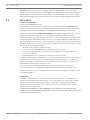
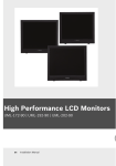
Connections on back of DIVAR 3000 (16-channel version)
12
14
16
CVBS MON. A
2
4
3
1
5
7
9
11
13
15
9 10 11 12
ON
13 14 15 16
OFF
0
NO1
C1
ALARM IN
1
CVBS MON. B
5 6 7 8
AUDIO OUT
3
AUDIO IN
1 Camera VIDEO IN BNC connectors
MIC IN
C3
10
VIDEO IN
8
NO2
C2
6
4
NO3
2
ALARM OUT
G
+ _
-
RS-232
+
G
VGA MON.A
RS-485
ETHERNET 12VDC
HDMI MON.A
9 RJ45 ethernet connector
2 CVBS output - Monitor A
10 VGA output - Monitor A
3 Audio inputs
11 HDMI output - Monitor A
4 Audio output
12 USB connector
5 Alarm inputs
13 RS485 connector for Dome control
6 RS232 connector for Dome control
14 Alarm outputs
7 Power ON/OFF switch
15 Microphone input
8 12 VDC Power connector
16 CVBS output - Monitor B
Notice!
The 4- and 8-channel DIVAR 3000 models have a slightly different back panel. VIDEO IN
connectors 5 to 16 for 4-channel (and VIDEO IN connectors 9 to 16 for 8-channel) are
disabled.
2013.11 | 1.1 | AM18-Q0668
Quick Reference Guide
Bosch Security Systems
Quick install | en
DIVAR AN 3000 / DIVAR AN 5000
11
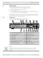
Connections on back of DIVAR 5000 (16-channel)
2
ON
6
4
8
10
12
14
16
CVBS MON. A
2
4
5 6 7 8
AUDIO OUT
9 10 11 12
13 14 15 16
1
1
3
5
7
9
11
13
15
CVBS MON. B
3
G
+12V
CTRL
C5
NO5
ALARM OUT
+12V
NO2
C2
C3
NO4
C4
NO3
NO1
C1
0
VIDEO IN
OFF
ALARM IN
G
+ _
G
+ _
G
RS-485 KEYBOARD
MIC IN
AUDIO IN
RS-232
VIDEO OUT
VGA MON.A
HDMI MON.A
e-SATA
ETHERNET
1 Power ON/OFF switch
10 RS232 connector for Dome control
2 Camera VIDEO IN BNC connectors
11 USB connector
3 CVBS output - Monitor A
12 e-SATA connector
4 Audio inputs
13 HDMI output - Monitor A
5 Audio output and MIC IN connector
14 VGA output - Monitor A
6 Alarm outputs
15 CVBS output - Monitor B
7 Alarm inputs
16 VIDEO OUT connectors (loop through)
8 RS485 and keyboard connectors
17 Power connector
9 RJ45 ethernet connector
Bosch Security Systems
Quick Reference Guide
2013.11 | 1.1 | AM18-Q0668
12
en | Quick install
DIVAR AN 3000 / DIVAR AN 5000
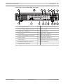
Connections on back of DIVAR 5000 (4/8-channel)
1
3
2
4
5
6
7
CVBS MON. A
8
2
4
5 6 7 8
AUDIO OUT
VIDEO OUT
1
1
2
3
4
5
6
7
8
CVBS MON. B
3
G
+12V
CTRL
NO5
C5
+12V
NO2
C2
0
C3
NO4
C4
VIDEO IN
NO3
OFF
NO1
C1
ON
ALARM IN
+ _
G
ALARM OUT
G
+ _
G
RS-485 KEYBOARD
MIC IN
AUDIO IN
RS-232
VGA MON.A
HDMI MON.A
e-SATA
ETHERNET
1 Power ON/OFF switch
10 RS232 connector for Dome control
2 Camera VIDEO IN BNC connectors
11 USB connector
3 CVBS output - Monitor A
12 e-SATA connector
4 Audio inputs
13 HDMI output - Monitor A
5 Audio output and MIC IN connector
14 VGA output - Monitor A
6 Alarm outputs
15 CVBS output - Monitor B
7 Alarm inputs
16 VIDEO OUT (loop through)
8 RS485 and keyboard connectors
17 Power connector
9 RJ45 ethernet connector
Notice!
The 4-channel DIVAR 5000 models have a slightly different back panel (VIDEO IN/OUT
connectors 5 to 8 are disabled).
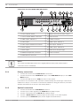
3.1.1
Primary connections
1.
Connect the cameras to the VIDEO IN BNC connectors.
2.
Connect monitor A to the VGA MON A output, or the HDMI MON A output, or the CVBS
MON A output.
3.
Connect the USB mouse to a USB port (front or back panel).
For first time use, the NTSC or PAL selection is determined by the camera type connected to
VIDEO IN 1 in step 1. If no camera is connected to VIDEO IN 1 during first time use, the video
standard is default and can be set in the Startup Wizard.
3.1.2
Optional connections
1.
Connect monitor B to the CVBS MON B connector.
2.
Connect up to 4 audio signals to the AUDIO IN RCA (CINCH) inputs.
3.
Connect 1 microphone to the MIC IN RCA (CINCH) output.
4.
Connect 1 AUDIO OUT RCA (CINCH) output to the monitor or an audio amplifier.
5.
Connect up to 16 ALARM IN inputs (via the supplied terminal blocks).
2013.11 | 1.1 | AM18-Q0668
Quick Reference Guide
Bosch Security Systems
DIVAR AN 3000 / DIVAR AN 5000
Quick install | en
6.
Connect up to 6 ALARM OUT outputs (via the supplied terminal blocks).
7.
Connect a pan/tilt/zoom control unit to the RS-485 or RS-232 port.
8.
Connect to your network via the ETHERNET connector.
9.
Connect extra video out cables to the VIDEO OUT ports if loop through is required to
13
other devices (only for DIVAR 5000).
10. If required, connect a Bosch Intuikey keyboard cable to the KEYBOARD connector using
the supplied adaptor (only for DIVAR 5000).
3.2
Powering up
For the DIVAR 3000:
1. Switch on all connected equipment.
2.
Connect the supplied external power adaptor to the AC power outlet.
3.
Connect the DC power cord to the 12 VDC connector on the unit.
4.
Turn on the unit power ON/OFF switch on the rear of the unit.
For the DIVAR 5000:
1. Switch on all connected equipment.
Bosch Security Systems
2.
Connect the power cable to the AC power outlet.
3.
Turn on the unit power ON/OFF switch on the rear of the unit.
Quick Reference Guide
2013.11 | 1.1 | AM18-Q0668
14
3.3
en | Quick install
DIVAR AN 3000 / DIVAR AN 5000
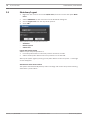
Login
The system login interface is shown in the following figure:
Figure 3.1: Login
When you startup the system for the first time, the Startup Wizard appears where you can
setup the system software. Here the default User ID is ADMINISTRATOR and the default
password is 000000 (six zeros).
Use the supplied USB mouse, front panel, remote control or keyboard (only on DIVAR 5000) to
input data and commands. See the descriptions in User controls and menus for how to use
the mouse, front panel and remote control.
Notice!
Unauthorized system use
For security reason, please alter your password after you first login.
Notice!
Account lock (only available in first release)
If you incorrectly login 5 consecutive times within a 30 minute period, the system will issue an
alarm and the account is locked; you must wait 30 minutes again for the account to be
unlocked.
When required, you can logout from the user interface using the Shutdown menu – see
Shutdown/Logout, page 20.
2013.11 | 1.1 | AM18-Q0668
Quick Reference Guide
Bosch Security Systems
DIVAR AN 3000 / DIVAR AN 5000
3.4
Quick install | en
15
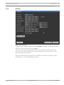
Startup Wizard
The Startup Wizard opens automatically after you log in for the first time. See following
screen:
Figure 3.2: Startup wizard first screen
Select a language and video standard from the drop-down menus and click <Next step>. The
wizard will guide you through the following steps:
1.
Choose to reset the startup wizard to run after the next system restart – see Reset startup
wizard, page 16.
2.
Assign General settings – see General, page 16.
3.
Assign Encoder settings – see Encoder, page 17.
4.
Assign Schedule settings – see Schedule, page 18.
5.
Assign Record settings – see Record, page 18.
6.
Assign Network settings – see Network, page 19.
7.
Finish the startup by clicking <Finished>.
8.
Confirm the setup by clicking <OK>.
Use the following buttons to navigate through the wizard screens and assign your correct user
settings:
–
<Cancel> exit the Startup wizard and immediately access the DIVAR user interface (this
action will automatically install all factory defaults for the remaining Startup wizard
screens)
Bosch Security Systems
–
<Next Step> go to the next wizard screen.
–
<Previous step> return to the previous Startup wizard screen
–
<Default> assign the factory defaults for the current setup screen
–
<Copy> copy the current screen settings for a channel to other channels
Quick Reference Guide
2013.11 | 1.1 | AM18-Q0668
16
en | Quick install
3.4.1
DIVAR AN 3000 / DIVAR AN 5000
Reset startup wizard
Figure 3.3: Startup wizard reset
If required, select the check box here to activate the Startup wizard after the next system
restart (this is only useful if you need to reconfigure the system during the next startup).
Later, during operation, you can also reset this mode in the General screen.
Click <Next step> for the next Startup wizard screen (General settings).
3.4.2
General
Figure 3.4: Startup general
Check the general settings on this screen:
–
If they are correct, click <Next step> to go to the next Startup wizard screen (Encoder
settings).
2013.11 | 1.1 | AM18-Q0668
Quick Reference Guide
Bosch Security Systems
DIVAR AN 3000 / DIVAR AN 5000
–
Quick install | en
17
If changes are required, use the drop-down menus and entry fields to assign the correct
settings (if you change the system time and/or date, click <Save> before continuing).
–
3.4.3
When ready, click <Next step> to move to the Encoder Startup wizard screen.
Encoder
Figure 3.5: Startup encode
Assign here the encoder settings and click <Next step> for the next Startup wizard screen
(Schedule settings). To save time when setting up channels, use <Copy> to copy settings from
one channel to other(s).
Bosch Security Systems
Quick Reference Guide
2013.11 | 1.1 | AM18-Q0668
18
en | Quick install
3.4.4
DIVAR AN 3000 / DIVAR AN 5000
Schedule
Figure 3.6: Startup schedule
Assign here all the schedule settings and click <Next step> for the next Startup wizard screen
(Record settings). Use <Copy> to copy settings from one channel to other(s).
3.4.5
Record
Figure 3.7: Startup Record
Assign here all the record settings and click <Next step> for the next Startup wizard screen
(Network settings):
–
Schedule: The selected channels will record according to the schedule setup (see
previous setup screen)
–
Manual: selected channels will automatically begin recording
–
Stop: No recording on the selected channels
2013.11 | 1.1 | AM18-Q0668
Quick Reference Guide
Bosch Security Systems
DIVAR AN 3000 / DIVAR AN 5000
3.4.6
Quick install | en
19
Network
Figure 3.8: Startup network
Assign here all the network settings and click <Finished> to complete the Startup wizard (you
will need to confirm the setup by clicking <OK>).
The system will automatically display the active view mode (with a maximum 16 camera
views). From here you can operate your system using the mouse, remote control or front
panel. See the following sections.
When you eventually need to log off from your system (or shut down completely), use the
Shutdown menu – see Shutdown/Logout, page 20.
Bosch Security Systems
Quick Reference Guide
2013.11 | 1.1 | AM18-Q0668
20
3.5
en | Quick install
DIVAR AN 3000 / DIVAR AN 5000
Shutdown/Logout
1.
Right-click the mouse to access the Quick menu; from here choose the option Main
menu.
2.
Select <Shutdown> on the main menu for the Shutdown dialog box.
3.
Choose Logout user from the drop-down options.
4.
Click <OK>.
Other options on the drop-down menu are:
–
Shutdown
–
Restart system
–
Switch user.
Logout with power button
Another way to stop all operations is:
1.
Press the power button on the front panel for at least 3 seconds.
2.
Switch off the power button in the rear panel to turn off the DVR.
Start up the system again by turning on the power button on the rear panel – a new login
screen will appear.
Auto Resume after Power Failure
The system will automatically backup video recordings and resume the previous working
status after a power failure.
2013.11 | 1.1 | AM18-Q0668
Quick Reference Guide
Bosch Security Systems
DIVAR AN 3000 / DIVAR AN 5000
4
First time operation | en
21
First time operation
Once the Startup Wizard steps have been completed, your monitor will show the normal live
mode with real time camera displays ready to operate your system.
From here, you can control your system via menus (Quick menu and Main menu) using the
mouse, front panel buttons or the remote control.
Notice!
The mouse is normally the preferred input device when setting up the system and entering
field values. Clicking the right mouse button is the quickest way to select and leave menus.
See the following descriptions:
–
Live viewing, page 21
–
Quick menu, page 24
–
Main menu, page 27
–
Mouse controls, page 25
For a detailed description of configuring and operating the system (plus all technical
specifications), refer to the Operator Manual on the supplied DVD.
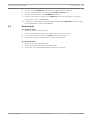
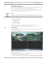
4.1
Live viewing
After you log in, the system is in live viewing mode with 1 to 16 camera images on the display.
See following example view.
Figure 4.1: Live view (4 camera views displayed)
This is the normal operating mode of the unit where live pictures are viewed from a maximum
16 connected cameras.
The system date and time is displayed in the top right corner of the screen, and the channel ID
is shown in the bottom left of each channel display.
–
Bosch Security Systems
To change system date and time, see general settings (Main Menu > Setting > General).
Quick Reference Guide
2013.11 | 1.1 | AM18-Q0668
22
en | First time operation
–
DIVAR AN 3000 / DIVAR AN 5000
To modify the channel ID, see display settings (Main Menu > Setting > Display).
Each channel view has one or more of the following icons displayed:
Recording – this icon is
Camera masking – the camera has been
displayed when a channel is
blocked
recording
Motion detection – a
No camera is attached to this channel or
movement has been detected
communication has been lost from this
in the camera view
camera
PTZ active If your camera is
equipped with a PTZ function,
you can pan, tilt and zoom the
live viewing image as
described in the PTZ function.
If multiple channels are displayed, you can double-click on a particular channel to show this
channel in full-screen (double-click on it again to return to multiple-channel view). The
currently selected channel is shown with a yellow border. From live mode, you can switch to
playback mode or access the main menu as described below.
Changing the display
1. Bring up the Quick menu.
2.
Select View 1, 4, 8, 9 or 16 and choose the corresponding Camera configuration.
Other functions in Live mode are:
–
Playback and zoom
–
PTZ
–
Sequence
Access to these functions requires the correct user level. Check with your administrator if you
do not have access.
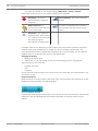
Playback and Zoom
Move the mouse to the top centre of the video of the current channel; the system pops up the
playback and zoom interface. See following figure.
Figure 4.2: Playback and zoom
If your mouse stays inactive in this area for more than 6 seconds, the control bar automatically
disappears. See the following table for detailed information on the two preview control
buttons.
2013.11 | 1.1 | AM18-Q0668
Quick Reference Guide
Bosch Security Systems
First time operation | en
DIVAR AN 3000 / DIVAR AN 5000
Icon name
Function
Realtime
Press to playback the previous 5-60 minutes recorded on the
playback
current channel (default is 5 minutes):
23
The playback screen supports drag and play function - use your
mouse to drag the play bar to any playback start time.
Use the pause and exit functions as required.
During the preview playback process
–
you can not see the channel title and record status of
current channel (they only reappear once you exit preview
playback)
–
you can not switch the displayed channel or change current
window-display mode
To set the Realtime play time, go to Main Menu > General.
Note: The system may pop up a dialog box if there is no
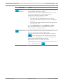
recorded data in the current channel.
Digital zoom
Zoom in on a specified zone of current channel (zoom-in
function is supported in multiple-channel view).
When you click on the zoom icon it will change to a new icon
; you can now select an area by holding down the left
mouse button and dragging an area on the screen. Release the
mouse and the selected area will be zoomed.
Right-click the mouse to exit the zoomed area.
Exit the digital zoom function at any time by clicking on the icon
again – it will change back to
Bosch Security Systems
Quick Reference Guide
.
2013.11 | 1.1 | AM18-Q0668
24
4.2
en | First time operation
DIVAR AN 3000 / DIVAR AN 5000
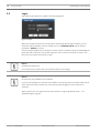
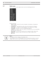
Quick menu
When in normal view mode, right-click the mouse for the following quick menu:
Figure 4.3: Quick menu
Here you can select:
–
View 1, 4, 9, 16 – choose here to view one-window, four-windows, nine-windows or
sixteen-windows
–
Pan/Tilt/Zoom – only possible if you have a PTZ camera attached and configured
–
Color setting – to change the color/hue/brightness of the viewed camera images
–
Search/Play –searching for records, and playing/exporting them
–
Sequence on – activate a camera tour sequence (to disable the tour, access Quick Menu
again and select ‘Sequence off’)
–
Alarm output – access the alarm output screen to configure the alarm output relays
–
Switch user –activate the Login screen where you can login as a different user
–
Main menu
Notice!
Pan/Tilt/Zoom and color settings in multi window mode
The Pan/Tilt/Zoom and Color setting applies for the currently selected channel. If you are in
multiple-window mode, the system automatically switches to the corresponding channel.
2013.11 | 1.1 | AM18-Q0668
Quick Reference Guide
Bosch Security Systems
DIVAR AN 3000 / DIVAR AN 5000
4.3
First time operation | en
25
Mouse controls
Mouse
Function
Left button
In Live mode, click once to select channel and choose other functions
In the Quick menu, use the left mouse button for the following options:
–
Go to the main menu (after selecting a menu item, left click again to view
menu content and make selections)
–
Modify a checkbox or motion detection status
When inputting data, one of the following input keypads appears (depending
on whether you need to enter alphanumeric or only numeric characters):
Left click the corresponding button on the keypad to input the required
characters (use Shift on alphanumeric keypad to switch between small/
capitalized)
Double-click
Implement a special control operation, e.g. double click an item in the file list
left button
to play the video
In multiple window mode, double-click one channel to view in full-window
mode; double-click current video again to go back to previous multiple
window mode
Drag mouse
with left
button
Select motion detection zone
Select privacy mask zone.
pressed
Middle scroll
wheel
In numeral input box, increase or decrease numeric value
Switch items in a check box
Page up or page down in a list
Bosch Security Systems
Quick Reference Guide
2013.11 | 1.1 | AM18-Q0668
26
en | First time operation
Right button
DIVAR AN 3000 / DIVAR AN 5000
In Live mode, the following quick menu appears:
If you are currently in a menu, right-click to exit the current menu without
saving any modifications.
2013.11 | 1.1 | AM18-Q0668
Quick Reference Guide
Bosch Security Systems
DIVAR AN 3000 / DIVAR AN 5000
4.4
First time operation | en
27
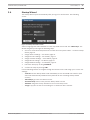
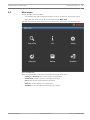
Main menu
Access the Main menu as follows:
–
Use the Enter key and the direction buttons on the front panel or the remote control
–
Right-click the mouse for the Quick menu and select ‘Main menu’
The Main menu has six menu selections, each with further submenus. See following figure.
Figure 4.4: Main menu
Move through the Main menu items and select the required sub-menu:
Bosch Security Systems
–
Setting and Advanced are used for system configuration
–
Search/Play is used to search for and play recordings
–
Info shows relevant system status information
–
Backup is used to backup your system files
–
Shutdown is used to logoff and shutdown your system
Quick Reference Guide
2013.11 | 1.1 | AM18-Q0668
28
4.5
en | First time operation
DIVAR AN 3000 / DIVAR AN 5000
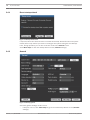
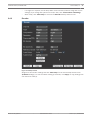
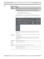
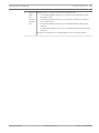
Search/Playback
Click Search/Play in the Main Menu (or from the Quick menu) for the following interface. See
following figure
Figure 4.5: Search/Play screen
ID
Name
Function
1
Display
Display of the currently chosen picture or file (supports 1/4/9/16-window
window
playback.)
Search
Here you can select to search for a picture (PIC) or a recorded file (REC).
type
Select to play from the read-write HDD or an optional connected external
2
device.
3
Calendar
If a date is highlighted blue then a picture or file is available for that date.
When in play mode, click the required date to see a trace of all recorded
files (or pictures) in the time bar on the bottom of the page.
2013.11 | 1.1 | AM18-Q0668
Quick Reference Guide
Bosch Security Systems
DIVAR AN 3000 / DIVAR AN 5000
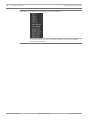
4
First time operation | en
Playback
Playback mode:1/4/9/16. (choose the required icon)
mode
–
and
channel
In 1-window playback mode: you can select 1-16 channels from the
drop-down menu
–
selection
pane
29
In 4-window playback mode: you can select 4 channels according to
your requirements.
–
In 9-window playback mode, you can switch between 1-8 and 9-16
channels.
–
In 16-window playback mode, you can switch between1-16 and 17-32
channels.
The time bar changes if you modify playback mode or channel option.
Bosch Security Systems
Quick Reference Guide
2013.11 | 1.1 | AM18-Q0668
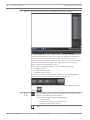
30
en | First time operation
5
DIVAR AN 3000 / DIVAR AN 5000
File list
Double click to view a list of recorded files for the selected day.
The file list displays the first channel of the recorded file (click the numbers
above to select another channel). The system can display max 128 files at
one time. Click once on a file to view the file details under the list, or
double click a file to playback the file on the screen. You can also select the
checkbox beside file(s), then select the ‘Save’ button to save files to a
device (see description below for ‘Save’).
The character shown beside each file has the following meaning:
–
R—Regular record
–
A—external Alarm record
–
M—Motion detect record
For a precise search for a time period, stop the current file being played
and enter a period in the time panel (shown above the list):
When ready, return to the original calendar and channel setup interface by
clicking
6
Play/
Play or Pause (the ‘pause’ button is displayed if the DVR is already
Pause
playing and you wish to pause the play)
There are three ways for you to begin playback.
–
The play button
–
Double click a valid period in the time bar
–
Double click a file in the file list
Stop
2013.11 | 1.1 | AM18-Q0668
Quick Reference Guide
Bosch Security Systems
DIVAR AN 3000 / DIVAR AN 5000
First time operation | en
31
Backward play
In normal play mode, left click the button, the file begins backward
play. Click it again to pause current play.
In backward play mode, click
to restore normal play.
In playback mode, click to play the next or the previous section
(click continuously to watch consecutive files from the same
channel.
In normal play mode, press pause then click
and
to begin
frame-by-frame playback.
In frame-by-frame playback mode, click
to restore normal
playback.
Slow play
In playback mode, click for various slow play modes such as slow
play 1, slow play 2, etc.
Fast forward
In playback mode, click to realize various fast play modes such as
fast play 1, fast play 2, etc.
Smart search – see description below
The audio volume for the video playback
Click in full-screen mode to snapshot 1 picture per second.
Digital When the system is in playback mode:
zoom
1.
Left-click the mouse in the screen and hold down the mouse
button.
Bosch Security Systems
2.
Drag to select a section then release the mouse button.
3.
Left-click in the selection for digital zoom of the selection.
4.
Right-click to exit zoom.
Quick Reference Guide
2013.11 | 1.1 | AM18-Q0668
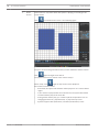
32
en | First time operation
7
DIVAR AN 3000 / DIVAR AN 5000
Smart
This function is only active when the system is playing a recording in full-
search
screen mode.
to activate smart search. See following figure.
Click
Use your mouse to drag and select zone(s) in the window to detect motion.
Click
again to begin smart search.
The system searches for motion in the chosen area(s).
When ready, click
again to stop smart search playback.
Extra notes on smart search:
–
As default, the system will view the whole play zone as a motion detect
region.
–
If you choose to play another file in the file list, the system will switch
to motion detect play of the other file.
–
During motion detect play, you cannot implement operations such as
changing the time bar, play backward, or play frame-by-frame.
–
2013.11 | 1.1 | AM18-Q0668
System supports 396 (22x18 PAL) and 330 (22x15 NTSC) zones.
Quick Reference Guide
Bosch Security Systems
First time operation | en
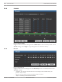
DIVAR AN 3000 / DIVAR AN 5000
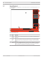
8
Time bar
33
Display the record type and the period for the current search criteria.
In 4-window playback mode, there are four corresponding time bars. In
other playback modes, there is only one time bar.
Click on a point in a colored zone in the time bar to begin playback at that
point.
When you first open Search/Play, the time bar begins at 0:00 hour, and will
zoom to the period of the current playback when playing the file. The bar
colors are:
–
Green for a regular record file
–
Red for an external alarm record file
–
Yellow for a motion detect record file
If required when playing a record, use the time bar unit to zoom in (see the
following description).
9
Time bar
The option includes: 24H, 12H, 1H and 30 minutes (the smaller the unit, the
unit
higher the zoom rate). This helps you to precisely locate a time in the time
bar when playing a record.
10
Save
Use to save/backup selected file(s) from the file list onto a memory device
(HDD, USB stick) as follows:
Click the save button for the backup menu (here you can choose a memory
device for the backup).
View the selected files to be saved (if required, click a file again to cancel
backup selection).
Click the start button to begin backup.
The system supports a max backup of 32 files from one channel (and from
max four channels).
11
Clip
Use to edit a file.
5.
Play the file to be edited and then click this button at the point you
want to edit...
6.
Wait for the slide bar in the time bar of the corresponding channel.
7.
Adjust the slide bar or input a time to set the file end time.
8.
Click this button again to stop edit and then save current contents in a
new file.
12
Bosch Security Systems
Record
This status line will change to show the current play mode (or pause) and a
type
checked box beside the scheduled record type (Motion, Alarm, Normal, All).
Quick Reference Guide
2013.11 | 1.1 | AM18-Q0668
34
5
en | Maintenance
DIVAR AN 3000 / DIVAR AN 5000
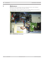
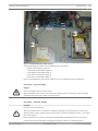
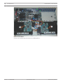
Maintenance
Maintenance of this unit is limited to external cleaning and inspection, plus installing or
replacing the internal lithium battery, the HDD or the DVD.
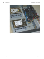
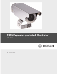
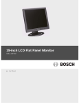
The following figures show the DIVAR 3000 and the DIVAR 5000 (with top covers removed)
and installed positions of the battery (1), DVD (2) and HDD (3):
1
2
3
Figure 5.1: DIVAR 3000 HDD and DVD installed
2013.11 | 1.1 | AM18-Q0668
Quick Reference Guide
Bosch Security Systems
DIVAR AN 3000 / DIVAR AN 5000
Maintenance | en
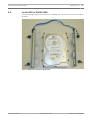
35
1
3
2
Figure 5.2: DIVAR 5000 DVD and HDD installed
See the following descriptions for installing these components:
–
Replace internal battery, page 37
–
Install HDD in DIVAR 3000, page 38
–
Install HDD in DIVAR 5000, page 41
–
Install DVD in DIVAR 3000, page 45
–
Install DVD in DIVAR 5000, page 47
Refer to the Appendix in the Operator Manual for recommended DVD and HDD types.
Precaution – electrical voltage
Danger!
Electrical voltage. Risk of electric shock.
When opening the top cover to service the unit, always make sure that the power has been
switched off and the power cable is disconnected.
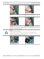
Precaution – connector damage
Caution!
Possible connector damage
When the DIVAR cover is removed for installing replacing or repairing internal components
!
(battery, HDD or DVD), always make sure you wear an approved ESD wrist strap – see Attach
ESD strap, page 37.
Notice also that some cables for both the DIVAR 3000 and DIVAR 5000 have a lock which
must be pressed and held when inserting/removing the cable. See following figures.
Bosch Security Systems
Quick Reference Guide
2013.11 | 1.1 | AM18-Q0668
36
en | Maintenance
DIVAR AN 3000 / DIVAR AN 5000
Press pin
Hold pin and connect cable
Press pin
Hold pin and connect cable
Precaution – processor/wiring damage
Caution!
Possible processor/wiring damage
!
When installing/removing a DVD/HDD, be careful that you do not damage vulnerable
components (e.g. when using a screwdriver, make sure it cannot slip off the screw and
damage the processor or wiring). See following figures.
2013.11 | 1.1 | AM18-Q0668
Quick Reference Guide
Bosch Security Systems
DIVAR AN 3000 / DIVAR AN 5000
5.1
Maintenance | en
37
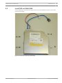
Attach ESD strap
Figure 5.3: ESD strap
The ESD strap is vital to prevent damage to ESD-sensitive parts when maintaining components
in an opened DVR cabinet.
Always attach the ESD strap around your wrist as follows:
1.
Slide the expandable strap over your wrist.
2.
Connect the clip on the flexible grounding cord to an unpainted ground point (or to an
approved ground point).
3.
Keep the strap on and connected while you touch, insert, or remove any ESD-sensitive
part.
5.2
Replace internal battery
This product uses a 3.0 V Lithium CR2032 battery (article number F01U099057) as the backup
power supply for internal system status (e.g. real time clock).
Under normal circumstances this battery will last for a minimum of 5 years. Low battery power
affects the DVR operation causing it to reset at every power-up. A log message appears when
the battery needs replacing (it should not be replaced unless required).
If the battery needs replacing, contact Bosch for assistance. Take note of the following
precautions:
Bosch Security Systems
–
Danger of explosion if battery is incorrectly replaced.
–
Replace only with the same battery type (or equivalent).
–
Dispose of used batteries according to the manufacturer’s instructions.
Quick Reference Guide
2013.11 | 1.1 | AM18-Q0668
38
5.3
en | Maintenance
DIVAR AN 3000 / DIVAR AN 5000
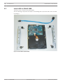
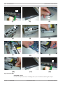
Install HDD in DIVAR 3000
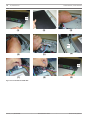
This DVR can fit a maximum two SATA HDDs.
See the following components and steps for installating HDD 1 (brackets and screws included
in package):
Figure 5.4: Install HDD 1 (DIVAR 3000)
2013.11 | 1.1 | AM18-Q0668
Quick Reference Guide
Bosch Security Systems
DIVAR AN 3000 / DIVAR AN 5000
Maintenance | en
39
4x
(1)
(3)
(2)
4x
(4)
4x
(6)
(5)
4x
(7)
(8)
(9)
4x
(10)
(11)
(12)
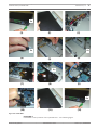
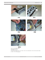
Figure 5.5: Install HDD 1
Install HDD 2
Install HDD 2 in the position of the optional DVD – see following figure:
Bosch Security Systems
Quick Reference Guide
2013.11 | 1.1 | AM18-Q0668
40
en | Maintenance
DIVAR AN 3000 / DIVAR AN 5000
Figure 5.6: Install HDD 2
Use the same install steps described for installing HDD 1.
2013.11 | 1.1 | AM18-Q0668
Quick Reference Guide
Bosch Security Systems
DIVAR AN 3000 / DIVAR AN 5000
5.4
Maintenance | en
41
Install HDD in DIVAR 5000
See the following components and steps for installing HDD 1 (brackets and screws included in
package):
Figure 5.7: HDD install components (DIVAR 5000)
Bosch Security Systems
Quick Reference Guide
2013.11 | 1.1 | AM18-Q0668
42
en | Maintenance
DIVAR AN 3000 / DIVAR AN 5000
2x
4x
(1)
(2)
(3)
2x
2x
(4)
(5)
(6)
(8)
(9)
4x
(7)
2x
(10)
(11)
(12)
Figure 5.8: Install HDD 1
Install HDD 1 and 2
Use the same procedure as for installing HDD 1, but include the following extra steps:
2013.11 | 1.1 | AM18-Q0668
Quick Reference Guide
Bosch Security Systems
Maintenance | en
DIVAR AN 3000 / DIVAR AN 5000
4x
(5a)
43
4x
(5b)
(8b)
(8a)
(10a)
Figure 5.9: Install HDD 1 and 2
Install HDD 3 and 4
Use the same install steps as for HDD 1 and 2, but install HDD 3 and 4 at the optional DVD
location. See following figure.
Bosch Security Systems
Quick Reference Guide
2013.11 | 1.1 | AM18-Q0668
44
en | Maintenance
DIVAR AN 3000 / DIVAR AN 5000
Figure 5.10: Install HDD 3 and 4
2013.11 | 1.1 | AM18-Q0668
Quick Reference Guide
Bosch Security Systems
DIVAR AN 3000 / DIVAR AN 5000
5.5
Maintenance | en
45
Install DVD in DIVAR 3000
See the following components and steps required for this installation (screws included in
package):
Figure 5.11: Install DVD components (DIVAR 3000)
Bosch Security Systems
Quick Reference Guide
2013.11 | 1.1 | AM18-Q0668
46
en | Maintenance
DIVAR AN 3000 / DIVAR AN 5000
4x
(1)
(3)
(2)
4x
(4)
(5)
(6)
4x
(7)
(8)
(9)
Figure 5.12: Install DVD in DIVAR 3000
2013.11 | 1.1 | AM18-Q0668
Quick Reference Guide
Bosch Security Systems
DIVAR AN 3000 / DIVAR AN 5000
5.6
Maintenance | en
47
Install DVD in DIVAR 5000
See the following components and steps required for this installation (spacers and screws
included in package):
Figure 5.13: Install DVD components (DIVAR 5000)
Bosch Security Systems
Quick Reference Guide
2013.11 | 1.1 | AM18-Q0668
48
en | Maintenance
DIVAR AN 3000 / DIVAR AN 5000
2x
(1)
(3)
(2)
4x
(4)
(6)
(5)
4x
4x
(7)
(8)
(9)
2x
(10)
(11)
(12)
Figure 5.14: Install DVD in DIVAR 5000
2013.11 | 1.1 | AM18-Q0668
Quick Reference Guide
Bosch Security Systems
Bosch Security Systems B.V.
Torenallee 49
5617 BA Eindhoven
The Netherlands
www.boschsecurity.com
© Bosch Security Systems B.V., 2013