1
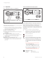
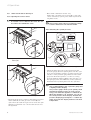
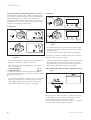
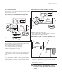
For the User
Instructions for use
ecoTEC
Wall hung room sealed fan assisted condensing boilers
ecoTEC plus 612
ecoTEC plus 615
ecoTEC plus 618
ecoTEC plus 624
ecoTEC plus 630
ecoTEC plus 824
ecoTEC plus 831
ecoTEC pro 28
GB
Contents
Appliance characteristics
Contents
Appliance characteristics
Appliance characteristics . . . . . . . . . . . . . . . . . . . . .
2
1
1.1
1.2
1.3
1.4
Notes on these instructions. . . . . . . . . . . . . .
Storage of the documents . . . . . . . . . . . . . . . . . .
Symbols used in this manual . . . . . . . . . . . . . . . .
CE marking . . . . . . . . . . . . . . . . . . . . . . . . . . . . . . .
Data badge . . . . . . . . . . . . . . . . . . . . . . . . . . . . . . .
3
3
3
3
3
2
2.1
2.2
2.3
2.4
Safety . . . . . . . . . . . . . . . . . . . . . . . . . . . . . . . .
Setup and adjustments . . . . . . . . . . . . . . . . . . . . .
What to do in an emergency . . . . . . . . . . . . . . . .
Safety instructions. . . . . . . . . . . . . . . . . . . . . . . . .
Modifications in and around the boiler . . . . . . .
3
3
3
4
4
Instructions on operation. . . . . . . . . . . . . . . .
Factory guarantee . . . . . . . . . . . . . . . . . . . . . . . . .
Two 2 year guarantee for ecoTEC plus
appliances . . . . . . . . . . . . . . . . . . . . . . . . . . . . . . . .
3.1.2 One year guarantee for ecoTEC pro appliances
3.1.3 Registering with us . . . . . . . . . . . . . . . . . . . . . . . .
3.1.4 Immediate help. . . . . . . . . . . . . . . . . . . . . . . . . . . .
3.2
Intended use . . . . . . . . . . . . . . . . . . . . . . . . . . . . . .
3.3
Care . . . . . . . . . . . . . . . . . . . . . . . . . . . . . . . . . . . . .
3.4
Recycling and disposal . . . . . . . . . . . . . . . . . . . . .
3.4.1 The appliance . . . . . . . . . . . . . . . . . . . . . . . . . . . . .
3.4.2 Packaging . . . . . . . . . . . . . . . . . . . . . . . . . . . . . . . .
5
5
3
3.1
3.1.1
4
4.1
4.2
4.3
4.3.1
4.3.2
4.4
4.5
4.5.1
4.5.2
4.5.3
4.6
4.6.1
4.6.2
4.6.3
4.7
4.8
4.8.1
4.8.2
4.8.3
4.9
4.10
4.11
2
Operation . . . . . . . . . . . . . . . . . . . . . . . . . . . . .
Overview of controls on ecoTEC plus. . . . . . . . .
Overview of controls on ecoTEC pro . . . . . . . . .
Initial checks before turning on . . . . . . . . . . . . .
Opening the service valves . . . . . . . . . . . . . . . . .
Checking the system pressure. . . . . . . . . . . . . . .
Turning the boiler ON . . . . . . . . . . . . . . . . . . . . . .
Domestic hot water with ecoTEC combination
boilers . . . . . . . . . . . . . . . . . . . . . . . . . . . . . . . . . . .
Setting the water temperature . . . . . . . . . . . . . .
Switching the warmstart function on and off. .
Drawing hot water (ecoTEC combination
boilers only) . . . . . . . . . . . . . . . . . . . . . . . . . . . . . .
Heating operation . . . . . . . . . . . . . . . . . . . . . . . . .
Setting the maximum radiator temperature
control . . . . . . . . . . . . . . . . . . . . . . . . . . . . . . . . . . .
Switching off heating (summer operation) . . . .
Setting a room- or outside temperature
controller . . . . . . . . . . . . . . . . . . . . . . . . . . . . . . . . .
Status displays . . . . . . . . . . . . . . . . . . . . . . . . . . . .
Troubleshooting . . . . . . . . . . . . . . . . . . . . . . . . . . .
Problems due to low system water pressure . .
Ignition problems . . . . . . . . . . . . . . . . . . . . . . . . . .
Flue problems . . . . . . . . . . . . . . . . . . . . . . . . . . . . .
Turning off the boiler . . . . . . . . . . . . . . . . . . . . . .
Frost protection . . . . . . . . . . . . . . . . . . . . . . . . . . .
Maintenance and customer service . . . . . . . . . .
The Vaillant ecoTEC plus and ecoTEC pro models are
compact, wall-mounted condensing appliances.
ecoTEC combination boilers plus and pro provides both
central heating and domestic hot water, with the domestic hot water supplied directly from the boiler. The boiler will operate automatically to provide domestic hot
water whenever a hot water tap is opened, and automatically adjusts to meet the demand for both central
heating and domestic hot water in the most economical
way.
ecoTEC system boilers provides central heating and
domestic hot water where a separate indirect hot water
cylinder is also incorporated to the system.
5
5
5
5
5
5
5
5
5
6
6
7
8
8
8
9
9
9
10
10
11
11
11
11
12
12
13
13
13
13
14
14
Instructions for use ecoTEC
Notes on the documentation 1
Safety 2
1
Notes on these instructions
To ensure clarity of information in instructions a new
European standard of advice and symbols is being introduced. To ensure compliance with this new standard the
following details are included.
The following information is intended to help you
throughout the boilers entire instruction pack.
We assume no liability for any damage caused by
non-observance of these instructions.
These appliances also comply with the requirements of
the directive on operating efficiency (Council directive
92/42/EEC).
Vaillant Ltd. support the Benchmark initiative.
At the rear of the installation manual, you will
find a Benchmark gas boiler commissioning
checklist. It is very important that this is completed correctly at the time of installation,
commissioning and handover to the user.
Other instruction supplied with this appliance
For the end user
Short operating instructions
(ecoTEC plus only)
no. 838404
Warranty card with return envelope
no. 802922
For the installer/service engineer:
Instructions for installation and servicing
no. 839592
Flue installation instructions
no. 835296
The instructions for any accessories and controllers
used also apply.
The Benchmark gas boiler commissioning checklist (in
the installation manual) should be completed by the
installer and/or the commissioning engineer.
If, after reading these instructions, you have any questions on the operation of the boiler, please contact
either your installer or Vaillant Technical Department.
1.1
Storage of the documents
Please store this user manual and all related documents
so that they are available whenever they are required.
If you move please pass on the documents to the buyer.
1.2
Symbols used in this manual
Please observe the safety instructions in this operating
manual for the operation of the appliance.
Danger
Immediate risk of serious injury or death.
Caution
Potentially dangerous situations for the product and environment.
Note
Useful information and instructions.
• Symbol for a necessary task
1.3
CE marking
The purpose of CE marking is to certify that the boiler
complies with the requirements of the directives
covering gasfired appliances (Council directive 90/396/
EEC) and electromagnetic compatibility (Council directive 89/336/EEC).
Instructions for use ecoTEC
1.4
Data badge
The type plate of the Vaillant ecoTEC is attached at the
factory to the bottom of the appliance.
2
Safety
2.1
Setup and adjustments
Installation and adjustment of the boiler as well as service, maintenance and repair of the boiler may only be
carried out by a competent person in accordance with
the Gas Safety (Installation and Use) Regulations 1998.
(In the U.K. “CORGI”. Registered installers undertake the
work to a safe and satisfactory standard). If the boiler is
installed in a compartment do not obstruct any purpose
provided ventilation openings, and do not use the compartment for storage purposes.
2.2
What to do in an emergency
Danger
Smell of gas. Risk of poisoning and explosion
due to a malfunction
If you smell gas or suspect a gas leak:
• Do not switch lights on or off.
• Do not use any other electrical switches.
• Do not use a telephone in the hazardous area.
• Do not use naked flames, such as matches or cigarette
lighters.
• Do not smoke.
• Turn off the gas supply at the gas meter.
• Open the windows and doors.
• Warn other residents.
• Get out of the house.
• Consult your gas supplier, service agent or other competent person.
3
2 Safety
2.3 Safety instructions
Always observe the following safety instructions and
regulations.
Danger
Inflammable mixtures of gas and air may
explode.
Do not use or store explosive or easily flammable substances such as petrol or paint in the
same room as the appliance.
Danger
Risk of poisoning and explosion due to a malfunction.
Never put the safety devices out of operation or
tamper with them so as to impair their function.
2.4 Modifications in and around the boiler
No modifications may be made to the following items:
- The boiler
- The gas, water and electrical supply
- The flue system
- The safety valve for the heating water
- Any structural changes around the appliance that
could affect the operational safety of the boiler.
Caution
Inappropriate modifications can cause damage.
Never tamper with the boiler or other parts of
the system.
Never attempt to perform maintenance or
repairs yourself.
- Do not damage or remove seals on components. Only
authorised engineers or our customer service may
removed sealed components.
Danger
Risk of scalding.
The water coming out of the tap can be very
hot (ecoTEC combination boiler only).
Caution
Risk of damage.
Do not use sprays, solvents, chlorinated cleaning agents, paint, adhesives or similar substances in the vicinity of the appliance. These
substances can cause corrosion, including in
the flue system.
Installation and setting
Important:
The appliance must be installed and serviced by
a Competent Person as stated in the Gas Safety
(Installation and Use) Regulations 1998. In IE,
the installation must be in accordance with the
current edition of I.S.813 ‘Domestic Gas Installations’, the current Building Regulations and
reference should be made to the current ETCI
rules for electrical installation.
Caution
The appliance may only be operated with its
case properly and permanently closed.
Otherwise, in unfavourable conditions, material
damage or even injury or death can result.
Filling pressure of the heating system
Regularly check the filling pressure of the heating system (see 4.3.2).
Leaks (ecoTEC combination boiler only)
If there is a leak in the water pipes between the appliance and the taps, immediately turn off the cold water
service valve and have your engineer repair the leak.
Frost protection
Your boiler is equipped with a frost protection function:
If the heating water temperature drops below 5 °C when
the main switch is ON, then the boiler goes into operation and heats the boiler circuit to approx. 30 °C.
Note
It cannot be guaranteed that water will circulate throughout the entire heating system.
If the boiler is not operated for several hours during
very cold weather there is therefore the possibility of
the system freezing.
Please ensure that if you are absent during a period of
frost the central heating remains in operation and all
rooms are kept above freezing point.
It must be remembered, however, that the boiler will be
automatically switched off by the built in monitoring
devices if certain faults occur, e.g. interruption in the gas
or electricity supply or faults in the flue gas system. To
overcome this possibility you can drain both the central
heating system and boiler.
Note
Frost protection and monitoring devices can
only function when the main switch of the unit
is set to the “I” position and the boiler is connected to the electrical supply.
4
Instructions for use ecoTEC
Instructions on operation 3
3
Instructions on operation
3.1
Factory guarantee
3.1.1
Two 2 year guarantee for ecoTEC plus appliances
Vaillant undertakes to rectify any manufacturing defect
that occurs within twenty-four months of the installation
date.
For the 2nd year of the guarantee to be valid an annual
service must be carried out by a CORGI registered installer one year after installation.
The cost of this annual service is not included in the
guarantee.
3.1.2 One year guarantee for ecoTEC pro appliances
Vaillant undertakes to rectify any manufacturing defect
that occurs within twelve months of the installation date.
3.1.3 Registering with us
Registration is simple. Just complete the Guarantee
Registration Card and return to Vaillant within 30 days
of installation. Your details will then be automatically
registered within the Vaillant scheme.
Note
No receipt will be issued.
3.3 Care
• Clean the exterior your appliance with a damp cloth
and a little soap.
Note
Do not use scouring or cleaning agent, which
might damage the housing or plastic fittings.
3.4 Recycling and disposal
Both your Vaillant ecoTEC boiler and its packaging consist mainly of recyclable raw materials.
3.4.1 The appliance
Do not dispose of your Vaillant ecoTEC boiler or any of
its accessories with household waste. Make sure the old
appliance and any existing accessories are disposed of
properly.
3.4.2 Packaging
Please leave the disposal of the transport packaging to
the expert company which installed the appliance.
Note
Please observe the applicable national legal
regulations.
3.1.4 Immediate help
If your Vaillant boiler develops a fault your first action
should be to contact your installer, as his professional
assessment is needed under the terms of our Guarantee.
If you are unable to contact your installer, phone Vaillant
Service Solutions: 0870 6060 777
3.2 Intended use
Vaillant ecoTEC boilers are state-of-the-art appliances
which have been constructed in accordance with recognised safety regulations. Nevertheless, there is a risk of
injury or death to the user or others and damage to the
appliance or other property in the event of misuse or
use for which the appliance is not intended.
The appliances are designed to generate heat for connected hot water central heating systems. Any other use
is considered to be use other than intended. The
manufacturer/supplier is not liable for any resulting
damage. The user alone bears the risk.
Intended use includes the observance of the operating
and installation manual and all other applicable documents, as well as adherence to the maintenance and
inspection conditions.
Caution
Any incorrect use is forbidden.
Instructions for use ecoTEC
5
4 Operation
4
Operation
4.1
Overview of controls on ecoTEC plus
Advanced multifunctional display system
1
1
10
2
9
i
i
F
F
P
P
3
bar
bar
4
8
7
6
5
Fig. 4.2 Display on ecoTEC plus
Fig. 4.1 ecoTEC plus controls
For access to the controls open the front flap by pulling
at the centre of the case strip.
1
2
3
4
5
6
7
8
9
10
Display indicating the current heating flow temperature, the pressure in the heating system, the operating mode or additional information
The “i” information button
Built in control/timer (if fitted)
Pressure gauge displaying the pressure in the heating system
Main ON/OFF control
“+” button for moving forward in the display
“-” button for moving back in the display or for displaying the pressure in the heating system
“Reset” button
Maximum radiator temperature control
Maximum hot water temperature control and warmstart ON/OFF control (ecoTEC combination boilers
plus only)
The ecoTEC plus appliance is fitted with a digital information and analysis system. This system provides information on the operating status of your appliance.
During normal operation, the display (1) shows the current heating flow temperature (in this example 45 °C). In
the event of a fault, an error code appears instead of the
temperature.
The display also gives the following information:
1
Indication of the current heating system flow
temperature or water pressure in the heating
system or display of a status or error code
Fan speed malfunction
Fan speed malfunction
As long as this symbol appears in the display, a
heating flow temperature and hot water outlet
temperature is set by the vrnetDIALOG accessory, which means the appliance uses temperatures other than those set using the controls (9)
and (10).
Dieser Zustand kann nur beendet werden:
- über vrnetDIALOG oder
- durch eine Temperaturänderung an den
Reglern (9) oder (10) um mehr als ±5 K.
Dieser Zustand kann nicht beendet werden:
- mit dem "Reset" button (8) oder
- durch Aus- und Einschalten des Gerätes.
Heating mode active
Illuminated:
Heating mode
Flashing:
Anti cycling mode active
6
Instructions for use ecoTEC
Operation 4
Hot water supply active
(ecoTEC combination boilers plus only)
Illuminated:
Hot water demand
10 Maximum radiator temperature control
11 Maximum hot water temperature control and warmstart ON/OFF
(ecoTEC system boilers only)
Illuminated:
Heating of an indirect hot water
cylinder turned on
Flashing:
Heating demand from the hot
water cylinder, burner on
Multifunctional display system
ecoTEC pro boiler has a multifunction display (1). When
the main ON/OFF control is in the “ON” position the display will normally show the system CH flow temperature
of water in the boiler circuit (45 °C in the example),
which confirms that the boiler is functioning correctly.
Warmstart system active
(ecoTEC combination boilers plus only)
Illuminated:
Warmstart turned on
Flashing:
Warmstart demand, burner on
Internal pump is running
i
F
P
Gas valve is activated
1
Flame with cross:
Boiler is at lock out and will display fault code
2
bar
Flame without cross:
Normal burner operation
4.2
4
3
Overview of controls on ecoTEC pro
Fig. 4.4 ecoTEC pro indicator lights
1
2
3
11
10
i
F
P
4
bar
5
9
8
7
6
Fig. 4.3 ecoTEC pro controls
1
2
3
4
5
6
7
8
9
Display indicating the current heating flow temperature, the pressure in the heating system or additional
information
Indicator lights to display the current operating mode
The “i” information button
Built in control/timer (if fitted)
Pressure gauge displaying the pressure in the heating system
Main ON/OFF control
“+” button for moving forward in the display
“-” button for moving back in the display or for displaying the pressure in the heating system
“Reset” button
Instructions for use ecoTEC
1
Display indicating flow temperature or the system
pressure or the relevent fault code.
2 Green warmstart indicator
Illuminated = Warmstart switched ON
Not illuminated = Warmstart is switched OFF and
there is no demand for hot water
Flashing = There is either a demand for hot water or
warmstart
3 Yellow indicator
Illuminated = Main burner ignited
4 Red indicator
Illuminated = Boiler is at lock out and will display
fault code
As long as this symbol appears in the display, a
heating flow temperature and hot water outlet
temperature is set by the vrnetDIALOG accessory, which means the appliance uses temperatures other than those set using the controls (10)
and (11).
Dieser Zustand kann nur beendet werden:
- über vrnetDIALOG oder
- durch eine Temperaturänderung an den
Reglern (10) oder (11) um mehr als ±5 K.
Dieser Zustand kann nicht beendet werden:
- mit dem "Reset" button (9) oder
- durch Aus- und Einschalten des Gerätes.
7
4 Operation
4.3
Initial checks before turning on
• On ecoTEC combination boilers only:
Ensure the cold water service valve (2) is open. This
can be checked by opening a hot water tap and ensuring water flows.
4.3.1 Opening the service valves
Note
If a bottom cover is fitted to the boiler the service valves are behind this cover.
Caution
The pressure relief valve is provided for safety
reasons and must not be interfered with.
2
4.3.2 Checking the system pressure
1
plus
pro
4
3
i
F
P
90˚
bar
2
Fig. 4.5 Opening the service valves on ecoTEC combination
boilers plus
Fig. 4.7 Checking the filling pressure of the heating system
1
• Check the water pressure of the system using the
pressure gauge (1) before putting the boiler into operation. For the heating system to operate properly, the
indicator on the pressure gauge must be in the dark
grey zone when the system is cold. This is a filling
pressure between 1.0 and 2.0 bar. If the indicator is in
the light grey area (below 0.8 bar), fill the system up
with water before putting the boiler into operation.
4
3
90˚
Fig. 4.6 Opening the service valves on ecoTEC system boilers
• Ensure that the service valves in the heating flow and
return (4 and 1) and the gas service valve (3) are
open. The flow, return and gas service valves are open
when the screwdriver slot is in the same direction as
the pipework.
8
1
bar
Note
The ecoTEC appliance has a pressure gauge and
a digital pressure display.
The pressure gauge allows you to quickly check
whether the filling pressure is in the correct
range, even when the appliance is switched off.
When the appliance is in operation, you can see
the exact pressure in the display. Activate the
pressure display by pressing the “-” button (2).
After 5 seconds the display returns to the flow
temperature.
Instructions for use ecoTEC
Operation 4
Note
Your appliance has a pressure sensor.
If the pressure falls below 0.6 bar the pressure
flashes in the display.
If it falls below 0.3 bar the appliance switches
off. The error message F.22 appears in the display. The system should be filled with water
before you start up the appliance again.
4.5
Domestic hot water with ecoTEC combination
boilers
The boiler should only be used when the heating system
contains water (see 4.3.2).
4.5.1 Setting the water temperature
plus
4.4
pro
Turning the boiler ON
2
2
3
i
F
i
P
F
P
bar
bar
Fig. 4.9 Setting the water temperature
1
Fig. 4.8 Switching on the appliance (example: ecoTEC plus)
• Use the main ON/OFF control (1) to switch the appliance on.
I:
“ON”
0: “OFF”
When you switch on the appliance, the current operating
status appears in the display (2).
To adjust the appliance according to your requirements,
read sections 4.5 and 4.6, which describe the setting
options for hot water supply and heating.
Caution
Risk of damage.
The boiler frost protection and monitoring systems are only active when the main ON/OFF
control of the appliance is in the “I” position
and it is not disconnected from the main power
supply.
• Switch on the appliance as described in section 4.4.
• The domestic hot water temperature can be adjusted
using the hot water temperature control (3).
• Turn the control clockwise to increase the temperature
and anti-clockwise to decrease the temperature. This
corresponds to:
- left limit approx.
35 °C
- right limit max.
65 °C.
Note
This control adjusts the maximum domestic hot
water temperature. If adjusting the control
upwards appears to have no effect on the temperature, then the boiler is already operating at
full output for the selected flow rate.
When you adjust the required temperature, the set value
is shown in the display (2).
After five seconds the display returns to standard mode
(the current heating flow temperature).
Caution
If you live in a hard water area please do not
set the control knob (3) above the mid (12
o’clock) position to prevent excessive scale formation.
Instructions for use ecoTEC
9
4 Operation
4.5.2 Switching the warmstart function on and off
The warmstart system of the ecoTEC combination boilers provides you with hot water at the required temperature immediately. To do this, the hot water heat
exchanger of the ecoTEC is kept at a pre-selected temperature level and the boiler will therefore periodically
operate to maintain this temperature.
ecoTEC pro:
1
b
a
ecoTEC plus:
2
1
b
b
a
c
1
b
c
1
2
Fig. 4.11 Switching the warmstart system on and off with ecoTEC pro
• Activate the warmstart system by briefly turning the
knob (1) all the way clockwise (position a). The green
LED (2) lights up.
Then select the required temperature, e.g. setting b.
Fig. 4.10 Switching the warmstart system on and off with
ecoTEC plus
The water is now kept constantly warm and is available
immediately as you turn on a tap.
• Activate the warmstart system by briefly turning the
knob (1) all the way clockwise (position a).
• Switch off the warmstart system by briefly turning the
knob (1) all the way anti-clockwise (position c). The
green LED (2) goes out. Then select the required hot
water outlet temperature again, e.g. setting b.
Then select the required temperature, e.g. setting b.
This corresponds to:
- left limit approx.
35 °C
- right limit max.
55 °C.
The water is now kept constantly at this temperature
and is available directly as you turn on a tap. The symbol
flashes in the display.
• Switch off the warmstart system by briefly turning the
knob (1) all the way anti-clockwise (position c). The
symbol disappears. Then select the required hot
water outlet temperature again, e.g. setting b.
4.5.3 Drawing hot water (ecoTEC combination boilers
only)
1
Fig. 4.12 Drawing off hot water (example: ecoTEC plus)
On opening a hot water tap (1) at a supply point (basin,
shower, bath, etc) the ecoTEC combination boiler will
automatically operate to deliver hot water.
On closing the tap the boiler switches OFF (or continues
to operate for central heating if required).
10
Instructions for use ecoTEC
Operation 4
4.6
Heating operation
4.6.2 Switching off heating (summer operation)
The boiler should only be used when the heating system
contains water (see 4.3.2).
plus
pro
4.6.1 Setting the maximum radiator temperature
control
plus
pro
i
F
P
2
1
1
bar
i
F
Fig. 4.14 Switching off heating (summer operation)
P
bar
You can switch off the heating in summer without
switching off the hot water supply.
• Turn the knob (1) for setting the maximum radiator
temperature all the way to the left.
4.6.3 Setting a room- or outside temperature controller
Fig. 4.13 Setting the maximum radiator temperature control
Set the maximum radiator temperature control to the
desired setting using the control knob (1).
We recommend the following settings:
– Left setting during spring and autumn,
– Middle setting during mild winter,
– Right setting during cold winter.
When you adjust the temperature, the set value is shown
in the display (2). After five seconds the display returns
to standard mode (the current heating flow temperature).
Normally you can adjust the knob (1) continuously up to
a flow temperature of 75 °C. However, higher temperatures can be set on your appliance, have your engineer
make adjustments so that you can operate the heating
system at higher flow temperatures.
1
i
F
P
2
Fig. 4.15 Setting a room- or outside temperature controller
• Set the room thermostat (1) and/or the thermostatic
radiator valves (2) according to the instructions supplied with the control(s).
Note
Vaillant offer room thermostat/time control
accessories which give accurate and economic
room temperature control as well as improved
comfort.
Instructions for use ecoTEC
11
4 Operation
The boiler will now operate automatically to provide central heating for the conditions selected on the external
controls (ecoTEC combination boilers will also provide
domestic hot water on demand).
After the boiler stops operating the pump will continue
to operate for a short period to fully disperse the heat
from the boiler.
Note
The boiler incorporates an anti-cycling economiser control to prevent energy wasteful ON
and OFF operation of the boiler for short periods when in the central heating mode. When
turning the room thermostat to a higher setting
there may therefore be a short delay before the
boiler operates.
4.7
Status displays
plus
2
1
F
P
bar
Fig. 4.16 Status displays
The status displays provide information on the operating
status of the appliance.
• Press the “i” button (1) to activate the status displays.
The display (2) then shows the current status code, for
example “S. 4” for burner operation. The table below
explains the most important status codes.
In switching phases, for example on starting up again
after the flame was extinguished, the status message
“S.” briefly appears.
• Press the “i” button (1) again to switch the display
back to normal mode.
12
Meaning
Displays during heating operation
S. 0
No heat required
S. 1
Pump running
S. 3
Boiler ignition
S. 4
Burner ignited
S. 6
Fan and pump overrun
S. 7
Pump overrun
S. 8
Anti cycling mode (after heating operation)
S.30
Room thermostat 3/4 no heating demand
S.31
Summer mode active
S.34
S.10
Frost protection mode
Displays in hot water operation (ecoTEC combination boilers only)
Hot water demand
S.14
Burner ignited
Table 4.1 Status codes (selection, a complete set of status
codes can be found in the installation and servicing
manual)
pro
i
Display
4.8 Troubleshooting
In the unlikely event that a problem occurs with the operation of the ecoTEC boiler, the following points should
be checked:
Boiler fails to operate:
– Is the gas supply turned on (see 4.3.1)?
– Is the water supply turned on (ecoTEC combination
boilers only, see 4.3.1)?
– Is there enough water in the heating system (see
4.3.2)?
– Is the electrical supply switched ON?
– Is the main ON/OFF control in the “ON” position
(switch position “I”, see 4.4)?
– Is there an ignition problem (see 4.8.2)?
Hot water operates but no central heating (ecoTEC
combination boilers only)
- Is the heating turned ON (see 4.6.1)?
- Are all external heating controls ON (see 4.6.3)?
Caution
Inappropriate modifications can cause damage.
If your boiler still does not operate then please
consult your installer or Vaillant Service
Solutions (0870 6060 777).
Instructions for use ecoTEC
Operation 4
4.8.1 Problems due to low system water pressure
The device switches to “Fault” if the water pressure in
the heating system is too low. This malfunction is indicated by the fault code “F.22” (dry fire) or “F.23” or
“F.24” (lack of water).
You can only start up the appliance again when the
heating system is sufficiently filled with water.
4.9
Turning off the boiler
i
F
P
4.8.2 Ignition problems
plus
1
pro
bar
2
1
Fig. 4.18 Switching off the appliance
i
F
• Turn the main ON/OFF control (1) to the „0“ position.
P
3
bar
Fig. 4.17 Troubleshooting
If the burner fails to ignite after five attempts, the
device does not start up and switches to “Fault”. This is
indicated by the fault code “F.28” or “F.29” in the display. On ecoTEC plus appliances the display also shows
the flame symbol with a cross through it (1). On ecoTEC
pro appliances, the red LED (2) also lights up.
Automatic ignition can only take place after you manually reset the fault.
• To reset the fault, press the reset button (3) and hold
it down for one second.
Caution
If the boiler still shuts off after three attempts
of resetting, please consult your installer or
Vaillant Service Solutions.
Caution
The boiler frost protection and monitoring systems are only active when the main ON/OFF
control of the appliance is in the “I” position
and it is not disconnected from the main power
supply.
To ensure that these protection devices remain active,
switch your boiler on and off using the external controller.
Note
If the appliance is switched off for a long time
(for example when you are on holiday) you
should also turn off the gas supply, the cold
water service valve and the electrical supply.
Note
Do not turn the ecoTEC system boilers OFF if a
hot water cylinder is also incorporated in the
system unless there is no demand for domestic
hot water.
4.8.3 Flue problems
The appliances are fitted with a fan. If the fan does not
work properly, the appliance will switch itself off.
The display shows the symbols and and the fault
message “F.32”.
Note
If contacting Vaillant Service Solutions please
remember to quote the fault code, as this will
help to pinpoint the fault.
Instructions for use ecoTEC
13
4 Operation
4.10 Frost protection
The frost protection feature only protects the boiler. Any
other parts of the system liable to frost damage should
be protected accordingly.
Caution
The frost protection and monitoring systems
are only active when the main ON/OFF control
of the appliance is in the “I” position and it is
not disconnected from the main power supply.
Frost protection function
The boiler has a frost protection function.
If the heating flow temperature falls below 5 °C with the
main ON/OFF control turned on, the appliance starts up
and heats the boiler to 30 °C.
Caution
Parts of the system may freeze.
The frost protection function cannot guarantee
that water flows through the entire heating system.
4.11
Maintenance and customer service
Inspection and maintenance
Permanent operational readiness, reliability and a long
service life require inspections and maintenance work to
be regularly carried out by a heating engineer or
Vaillant.
For further details please contact Vaillant Service
Solutions: (0870 6060777).
Danger
Risk of injury and damage due to improper
handling
Never attempt to perform maintenance or
repairs on the appliance yourself.
Have a specialist heating company do the work.
We recommend signing a service agreement.
The reliability of the appliance can be impaired,
resulting in damage to property or personal
injury if maintenance work is not carried out.
Regular servicing ensures maximum efficiency and economical operation of your gas wall heater.
14
Instructions for use ecoTEC
Instructions for use ecoTEC
15
838402_01 GB 02 2005