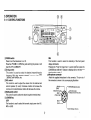
1
AR-147
/ AR-247
AR-447
MOBILE TRANSCEIVER
USER'S MANUAL
~
ADI
Cornmurucations
NOTE:
Thank you for purchasing this VHF/UHF mobile transceiver.
IMPORTANT
If disregarded, inconvenience only, no risk of equipment damage
or personal injury.
Please read this instruction manual carefully before attempting
operation.
CAUTION:
SAVE THIS INSTRUCTION MANUAL.
CAUTION:
Equipment damage may occur, but not personal injury.
Long transmission or extended operation in the HI power mode
might cause the rear of this transceiver to get warm.
Do not place the transceiver where the heat sink (rear panel)
might come in contact with plastic or vinyl surfaces.
This Instruction Manual covers the following models.
AR-147
144MHz FM TRANSCEIVER
AR-247
222/230/250MHz FM TRANSCEIVER
AR-447
430/440MHz FM TRANSCEIVER
FCC WARNING
This equipment generates or uses radio frequency energy.
Changes or modifications to this equipment may cause harmful
interference unless the modifications are expressly approved in
the instruction manual. The user could lose the authority to
operation this equipment if an unauthorized change or
modification is made.
1
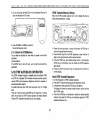
1. BEFORE OPERATION
3
2. SPECIFICA"'rIONS
5
3. ACCESSORIES
4. INSTALLATION INSTRUCTION
5. OPERATION
CONTROL FUNCTION.....................
RECEIVER OPERATION
Reception
Frequency Selection
Frequency Step Selection
TRANSMITTER OPERATION
Transmit Basics
Time-out Timer(TOT)
MEMORY
Memory Channels
Initial State
System Memory Initialization
Specific Memory Channels
Memory Entry
Memory Channel Recall..
Memory Shift.
Memory Channel Clear
SCAN
Scan Operation
Hold/Resume Programming
Band Scan
Programmable Band Scan
Memory Channel Scan
Memory Channel Lockout.
DUAL-WATCH OPERATION
6
6
9
9
14
:
15
15
16
16
17
17
17
18
18
19
19
19
20
20
20
21
21
22
22
2
REPEATER OPERATION
Transmitter Offset.
Automatic Repeater Offset.
Reverse Function
Tone Operation
ClCSS Tone Selection
DCS Code Selection
CTCSS/DCS FEA1"URE SELECTION
CTCSS Tone/DCS Code Scan
C.SQ(Code Squelch System) OPERATION
PAGING
DTMF CODE DECODING FUNCTION
DTMF AUTODIALER OPERATION
DTMF REDIALER OPERATION
KEYPAD DIRECT FREQUENCY ENTRy
APO(Automatic Power Off)
DIM(Dimmer)
BEEP
LOCK
CHANNEL DiSPLAy
AM RECEPTION(AR-147 option only)
6. KEY FUNCTION L1ST.
36
37
37
37
37
38
38
39
39
40
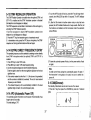
7. MAINTENANCE
GENERAL INFORMATION
SERViCE
IN CASE OF DIFFiCULTy
42
42
42
43
24
24
24
25
25
26
27
27
27
30
35
(..
The power requirement is 13.8 VDC.
Never attempt connection to a 24 VDC source.
BEFORE OPERATION
TO PREVENT ELECTRIC SHOCK, FIRE AND OTHER INJURY.
PLEASE NOTE THE FOLLOWING:
To avoid risk of electric shock , under no circumstances should the
unit be opened .
Do not place this unit, where it will be exposed to direct sunlight or
close to heating appliances.
Do not place the Unit in areas off excessive dust, high humidity or
on unstable surfaces.
To ensure good ventilation, do not put anything on top of the cabinet
and allow at least 15cm (6 inch) of space behind the unit.
Do not drop pieces of metal, needles, coins and other electrically
conductive materials into the unit.
3
Do not touch the power plug when your hands are wet.
CLEANING
1. Turn the power off, before cleaning the unit.
2. Do not use any type of abrasive pad, thinner. benzine or any
substances which may damage the unit.
3. Wipe the front panel and other exterior surfaces of the with a soft
dry cloth or a soft cloth lightly moistened with water. '
Do not pull the power cord, when disconnecting it from the AC wall
outlet. Grasp the plug and ensure that your fingers do not touch the
live pins.
If an abnormal odor or smoke is detected, immediately turn the
power off and pull out the power plug. Connect the ADI service
station or our dealer.
4
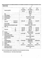
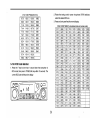
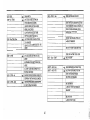
2. SPECIFICATIONS
AR-147
144 t0148(USA)
144 to146
Frequency range (MHz)
(ij
~
CD
c
Q)
CJ
Mode
Antenna impedance
Operating temperature
Power requirements
Ground
Current drain
CD
:s::
'E
en
c
ctl
t=
~
Q)
>
'mo
CD
a:
AR-247
AR-447
222 to 225(USA)
430 to 440
230 to 250
250 to 270
F3E(FM)
SOQ
-20·C to +60°C (-4·F to +140·F)
13.8V DC ±15 % ( 1 1 . 7 - 1 5 . 8 V )
Negative
Less than 9A
Lessthan10A
Less than 12A
------Less than 0.6A
Less than ±5ppm
140x40x166(5-1/2" x 1-37/6411 X 6-17/32")
1.2(2.65Ibs)
Approx 60W
Approx 30W
Approx 3SW
Approx 25W
Approx 15W
Approx
15W
,.
Approx 7W
Approx 7W
Approx 7W
Reactance modulation
Less than -80dB
Less than -70dS
Less than -65dB
±5kHz
"Less than 3%(300 to 3000 Hz)
2.2kQ
-'Dual conversion superheterodyne
10.7MHz/455kHz
30.85MHz/455kHz
[ 30.85MHz/455kHz
Less than 0.18 uV
70 dB
70 dB
65 dB
Less than 0.1 uV
Less than 0.177 uV
Less than 0.177 uV
More than 2W across 80 load
-,.
80
_._-
Transmit mode
Receive mode
Frequency Stability
Dimensions (WxHxD) (mm)(Projections included)
Weight (kg)
HI
Output power
MID
LOW
Modulation
Spurious radiation
Maximum frequency deviation
Audio distortion(at 600/0 modulation)
Microph01'!e impedance
Circuitry
Intermediate frequency
1st / 2nd
Sensitivity (12dB SINAD)
Selectivity
Squelch sensitivity
Audio output(1 00/0 distortion)
External speaker impedance
Note:l.Circuit and ratings are subject to change without prior notice due to advancement in technology.
2.Recommended duty cycle: 1 minute:Transmit, 3minutes Reception.
5
(..
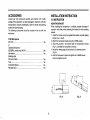
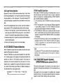
ACCESSORIES
INSTALLATION INSTRUCTION
Unpack your new transceiver carefully, and examine it for visible
damage If the equipment has been damaged in shipment, notify the
transportation company immediately. Save the boxes and packing
material for future shipping.
The following accessories should be included in the box with the
transceiver.
4.1 INSTRUCTION
DTMF Microphone
MC147D
or
Dynamic Microphone
(GENERAL market only) MC147
Hex wrench
Stacking plate
DC power Cable
Fuse
Instruction Manual.
Warranty Card
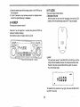
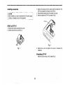
MOUNTING BRACKET
When installing the transceiver in a vehicle consider the ease of
operation and safety when selecting the location for the mounting
bracket.
1. Install the bracket using the supplied flat washer and self tapping
screws (4 pc s. each).
2. Attach the transceiver loosely using the 4 SEMs screws.
3. Align the grooves in the bracket with the transceiver's screws
(Fig. A ) and slide the transceiver to the rear.
4. Adjust the viewing angle in the bracket to the desired position
(Fig. B).
5. Hold the transceiver in place and tighten the 4 SEMS screws
using the supplied wrench.
1 ea.
1 ea.
1 ea.
1 ea.
1 ea.
1 ea.
1 ea.
F~.A
6
Ag. B
4-2 CONNECTOR
4·2·1 Mobile Installations
Make sure the positive 1+) and negative 1- t lead polarity Is correct
when connecting to the battery.
Cautions:
1. Before installing the power cable, be sure to remove the
negative lead from the battery for safety.
2. After installation and wiring, be sure to double check fer
correct installation before reconnecting the negative lead
to thebattery terminal.
3. If the fuse opens, be sure to check the each conductor has
been damaged by short circuiting, etc. Then replace with a
new fuse of the same rating.
4. After completing the wiring, wrap the fuse holder with heat
resistant tape to protect against heat and moisture.
5. Do not remove the fuse even if the power cable is too long.
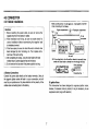
Engine compartment - Jl- Passenger compartment
Fuse
~
Red
Black
\
Battery
A. Battery Connections
Connect the power cable directly to the battery terminals. Using of
the cigarette lighter socket will lead to a poor connection. and will
result in poor performance. Pay close attention to the polarity of the
cables when connecting them to the battery.
Select a location _ a
tht PDwa, cable Ie pr..tec:ted !rom Ma.. mol."
tuN Of abr.1lon wn.n
lleCUring the cable.
B. Ignition Noise
This transceiver has been designed to suppress ignition noise;
however, if excessive noise is present, it may be necessary to use
suppressor spark plugs (with resistors).
7
ACCESSORIES
INSTALLATION INSTRUCTION
Unpack your new transceiver carefully, and examine it for visible
damage If the equipment has been damaged in shipment, notify the
transportation company immediately. Save the boxes and packing
material for future shipping.
The following accessories should be included in the box with the
transceiver.
4.1 INSTRUCTION
DTMF Microphone
MC147D
or
Dynamic Microphone
(GENERAL market only) MC147
Hex wrench
Stacking plate
DC power Cable
Fuse
Instruction Manual.
Warranty Card
MOUNTING BRACKET
When installing the transceiver in a vehicle consider the ease of
operation and safety when selecting the location for the mounting
bracket.
1. Install the bracket using the supplied flat washer and self tapping
screws (4 pc s. each).
2. Attach the transceiver loosely using the 4 SEMs screws.
3. Align the grooves in the bracket with the transceiver's screws
(Fig. A ) and slide the transceiver to the rear.
4. Adjust the viewing angle in the bracket to the desired position
(Fig. B).
5. Hold the transceiver in place and tighten the 4 SEMS screws
using the supplied wrench.
1 ea.
1 ea.
1 ea.
1 ea.
1 ea.
1 ea.
1 ea.
Fig. A
6
-'.q
Ag.B
4-2-2 Fixed Station
Match the impedance of the coaxial cable and that of the antenna so
that the SWR is less than 1.5 to 10. The protection circuit in the
transceiver will activate if the SWR is particularity poor (greater than
3 to 1).
High SWR values will cause the transceiver output to drop, and may
lead to TVI or BCI reports.
A regulated DC power supply (13.8 VDC capable of supplying at less
11 Amperes) is required.
1. Never connect the AC power cable to the AC until all other
connections have been made.
2. Before connecting and disconnecting the power connector, be
sure to turn OFF the POWER switches of both the transceiver
and the DC power supply.
3. Observe polarity of the DC power cable. The Transceiver
operates on 13.8 VDC, negative ground. Battery polarity must
be correct. The power cable is color coded:
Red ~ + (Positive polarity)
Red ~ - (Negative polarity)
4. The transceiver has voltage protection which keeps the voltage
under 18VDC.
5. Once the voltage is over 18VDC, the transceiver will shut
down automatically. To restart the system, adjust the voltage
to 13.8VDC and switch off the power then switch on again.
CAUTION:
We recommend that you install a high quality lightening arrestor
in your antenna lines for protection again fire, electric shock,
personal injury, or damage to the radio itself.
4-2-3 Antenna
The type of antenna that is use will greatly affect the performance of
the transceiver. Use a properly adjusted antenna, of good quality, to
enable your transceiver to perform at its best. The antenna input
impedance is 50 ohms. Use 50-ohm coxial cable such as RG-8U or
8D-2V for this connection. If the antenna is far from the transceiver
the use of low coaxial cable, such as RG-8U is recommended.
8
®®
5 OPERATION
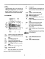
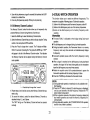
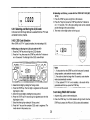
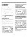
5-1-1 CONTROL FUNCTIONS
VFO MR MHz
( II II )
U-V M LOCK
&1mi
/11'0
-
-
+
1: IKl lQO(
188.8.8.8.8. S~88
HM..[JIE]OIIlDlIIOIIIOIllOIJC!ClO TXF
®
DIM
(DPOWER switch
Press to turn the transceiver on or off.
Press the VFO/M~ V or MRIM key and switching the power on will
reset the VFO or MEMORY.
This function is used to select the intensity of the front panel
display illumination.
\
Pressing the F key for longer than 1 second and then press the
LOW/DIM key while the F indicator is flashing will turn the time-out
timer function on and off.
@Microphone connector
Attach the supplied microphone to this connector. The pin out of
the connector is shown in the accompanying illustration.
@Tuning control
This control is used to select the desired transmit/receive
frequency, MHz step, memory channel, frequency step, tone
frequency, scan direction. etc.
®VOL control
This control is used to adjust the volume from the internal and
external speaker (if used). Clockwise rotation will increase the
volume and counterclockwise rotation will decrease the volume.
@SQ(Squelch) control
This control is used to select the desired squelch threshold level.
® LOW/DIM key
LOW
This function is used to select the transmit output power level (HI,
MID or LOW)
(j)GND-----.
CD MIC
(Microphone Audio) .........~_
(g)PTI
ellGND (Microphone audio)
<ro RX Audio Output
(Approx 100 mVJ10 k ohm)
(PUSh 10 Talk)
@ON
@Up----'
® 8 VDC (Max 150 mAl
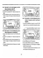
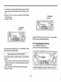
9
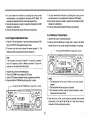
CD®®
mode. The Tuning control can then be used to select the desired
memory channel.
a __
~
(" II..,,)
t.l-V
M LOCK
'J
lOI"tl.W.
IiiliiIIiI!I
N'O
-1..'0'+
.,
SQ
L=<
188.8.8.8.8. S~88
0
0
nononmDmnmam",
@)
~
@§)o@
Press the key for longer than 1 second will initiate memory
channel scanning.
© ( II )
~I~~
DIM
~~©
9
Pressing the key within 10 second of pressing the F key will store
the display data into memory.
In the MR channel mode pressing the F key for longer than 1
second and then pressing the MR key will cause the Memory
channel to skip during Memory channel scan mode.
'
<D VFO/M~ V key
This key is used to VFO operation after operating in the MR or
CALL channel mode. Pressing this key will allow the turning
control and microphone UP/ON keys to increase or decrease the
operating frequency.
If you hold and press this key while you turn on the PWR
switch you will clear all the microprocessor's operator programmed
l
memory section.(system reset)
@ MHz/LOCK key
This key is used to tell the microprocessor that you wish to turning
the operating frequency in 1 MHz step. If the OTMF board is
installed, you also could enter the frequency with the 16-tone OTMF
keypad directly.
Press and hold the key for longer than 1 second to initiate VFO
scan. Pressing the key after scan has been initiated will cause
scan to stop.
Pressing the key within 10 seconds of pressing the F key will copy
the memory channel or call channel data to the VFo. This allows
you to change parameters of the channel without actually
changing the data that has been stored in memory.
Pressing this key within 10 seconds of pressing the F key will
cause the key lock function to activate, protecting the currently
display data from accidental erasure.
Pressing the key F key for longer than 1 second and then pressing
the VFO key will allow you to set the offset frequency.
Pressing the F key for longer than 1 second and then pressing
MHz/LOCK key while the indicator is flashing will turn the
AUTOMATIC POWER OFF function on or off.
If you press and hold the VFO key while you turn on the POWER
switch you will reset the microphone's VFO memory, without
destroying the memory channel or call channel data. (VFO Reset)
@MR/M key
This key is used to select MR (Memory Recall) mode from the VFO
10
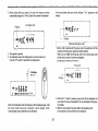
..
o
(M-V
1111)
~O~"~
... lOCI<
~
1OraK""
IHlOOIII
-IIE\/+"[
OQI1rJ(
~BB.8.8.8.8. S~B8
©(
:2J1-©
DIM
II
and scan step size. Use the tuning control to select the desired
tuning step and then press any front panel key except the PWR
switch to return to the normal frequency display.
@ TONE/DUAL key
TONE (CTCSSJDCS) function
Pressing this key by itself causes the radio to select the desired
subaudible tone signaling mode. When the "T.n indicator is
illuminated in the display the transceiver will transmit the the
selected CTCSS tone. When the "T.SO" indicator is illuminated the
transceiver will both transmit the subaudible tone and will also
remain squelched until the selected CTCSS tone is received.
When the "DCS" and "T," indicators illuminated, the Transceiver will
transmit the selected DCS code. If the "SO" indicator also
illuminated, the transceiver will remain squelched until the selected
DCS code is received.
TONE (CTCSS/DCS) selection
Pressing the F key for longer than 1 second and then pressing the
TONE/DUAL key will allow you to select the desired subaudible
tone. To change to a different subaudible tone rotate the turning
control or press the UP/ON switches on the microphone until the
desired subaudible tone appears in the display. To return to the
normal frequency display you can press any front panel key
except the PWR switch.
DUAL function
If you press the F key momentarily and then press the
TONE/DUAL key, DUAL function will be activated.
This function allows you to watch two different frequencies. The
Transceiver is capable of following types of dual-watch
operation.
(1) Listen on thedial-frequency and the memory frequency under M1.
(2) Listen on the dial-frequency and one of the memory frequencies.
(3)Listen on the dial-frequency and a memory frequency under
scanning.
)
lI>'_omomooomomoaon' so
/I~ CDC{§) @) @§)o~
©i
@CALLkey
@ ® ® CD
Press this key to activate the call channel function. Press the F
key momentarily and then press the CALL key to store the
currently displayed data into the CALL channel(except that
PAG/C.Sa activated in VFO mode)The radio will allow you up to 10
seconds to press the CALL key after pressing the F key.
Pressing the F key form longer than 1 second and then pressing
the CAli key will enable/disable the programming scan mode.
Press the key within 10 seconds of pressing the F key while
PAG/CSO is active will allow you to change the DTMF transmitting
delay time.
® SHFT/REV key
SHIFT function
Pressing this key alone to select the desired transmitter offset
feature. Pressing the key will cause the radio to shift from one
offset feature to the next, i.e. n-J1(minus offset) to n+n(plus offset)
to"- +n(automatic repeater mode), then back to simplex mode
where no indicator shows.
REV function
Pressing the key within 10 seconds of pressing of pressing the F
key will reverse the transmit/receive frequencies during repeater
operation.
If you have selected simplex this key will not functlon!
Pressing the f= key for longer than 1 second and then the
SHFT/REV key will allow you to select the desired VFO tuning step
11
,
1
.
~
I
~
, [i
,
~
I
~-
i
.i
,
i
j'
~
t
1-'
:
','
;,
,
:1
, J
l
,
~
;
r ~
,
,
([) DTMF key
Pressing this key alone to select the PAG, csa 'function if the
DTMF board is installed. Otherwise, a BU-sound will be
generated. Pressing the F key for longer than 1 second and
pressing the DTMF key will turn the BEEP function OFF or ON.
@)TX
On during transmit.
On whenever the function has been depressed. Also
shows the last memory channel number that has been
selected.
@LOCK
On when the Lock function has been activated.
@
Indicates the active memory channel number. SKP
~
indicates that the channel is lock out.
@T.Sa
On when the CTCSS/OCS Decode and Encode function
has been activated.
L_--On when the CTCSS/DCS Encode function has been
activated.
@REV
On when the Reserve function has been activated.
@-+
Display the selected transmitter Offset direction.
Both - and + light when during Automatic Repeater
function is activated.
@APO
On when the Automatic Power Off function has been
activated.
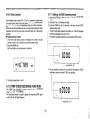
®
Displays the operating frequency to the nearest kHz diqit;
@F
IMJBB
5~ 1-2
LCD Display Panel
CD
@l19@@ @ @
t--l-
@~TOT O~L
~--M=t---t--sa LDCK~
--~
APO -
REV
+ T.
~[@] ~ ...
BBBB
@@=t=IB
· .58
(2)
•
@
I
r
@ Q)
@
i
BB,
~cs IlUS'iIDrnD~DImDI7JD[I]DOD ~
TX
'--t---i------------i------------t(J)@
CDTOT
@SCAN
®
@
Q)HML
On when the Time Out Timer function has been activated.
On when the VFO/MR SCAN function has been
activated.
On when the Busy SCAN flag is active.
On when the DTMF PAGING function is active.
On when the code squelch function has been activated.
On when DCS(Digital Code Squelch} function has been
activated.
Indicates the relative output power setting for transmit.
® IBUSYI
On when the squelch opens.
®
This level meter indicates the relative receiver signal
@B
@PAG
@C.SQ
@DCS
BB.B.B.B.B.s or the tone frequency etc.
®B
@DUAL
ornO())O[Slomo[li[JO~ strength or the relative transceiver power output.
12
On when DTMF Autodialer function has been
activated.
On when DUAL-watch function is active.
5-1-3 Rear Panel
+
5-1-4 Microphone
+
~-<D
Q) ANTENNA connector
Attach an antenna with a low SWR and impedance of 50 ohms.
® 13.8 VDC power input connector
Connect the supplied DC power cable to this connector.
Pay close attention to the polarity. Red is positive and black is
negative.
@ Fuse holder
Contains a required fuse.
Do not use a larger fuse as damage might result to the transceiver.
@) External speaker jack
This jack is used to connect an external speaker. The speaker
should have an impedance of 8 ohms.
Q) ®UPJDOWN switches
These switches can be used to increase or decrease the VFO
frequency, the Memory channel number, and the subaudible
tone etc..
@ PTT(push to Talk) switch
The transceiver will transmit whenever this switch is depressed.
G)CALL Key
This key functions just like the CALL key on the front of the radio.
Repeater Access Tone
The transceiver will transmit with repeater access tone whenever
this switch is depressed in Tx mode.
The repeater access tone could be selected as 1450, 1750, or
2100Hz.
13
@VFOkey
This key functions just like the VFO key on the front of the radio.
@MRkey
This key functions just like the MR key on the front of the radio.
(f) MHz key
This keyfunctions just like the MHz key on the frontof the radio.
5-2 RECEIVER OPERATION
Audio confirmation is provided whenever a front panel key is
depressed. You can disable this function by pressing the F key for
longer than 1 second and then pressing the DTMF key.
5-2-1 Reception
1. Connect the power supply, antenna, and microphone and then
adjust the controls as follows:
Power switch
OFF
Volume Control.
Full Counterclockwise
Power switch of power supply
(Fixed station)
OFF
Control.
Full Counterclockwise
2. Turn on the Power Supply and then turn on the transceivers
PWR switch. The display should indicate a frequency. Fig.1
shows examples of frequencies that will appear on the various
models. In addition to the frequency you may see one or more
control indicators illuminate on the display.
ee08
8888
GGGll
888G
888G
sa
.8 JIr---+----------1
---r--------1
9
AR-147
AR-247
1"-"----"--"-"-")
!
® 16- Tone DTMF keypad
These buttons are used to activate the DTMF encoder.
@)LOCKkey
This key will deactivate all functions of the microphone except the
PTI function and DTMF key pad.
14
I~ 'i.O 00
__.
L.~
1-----·---------·----··,
AR-447
1-··-··-··-..·-------··1
i !L.. 223.500 .JI !L .. li..,O.OOO
.. .J
L _ ••
•• _ .
L _ ..
•• _
••
f
.J
• VFO Mode Operation Frequency Selection
1. Press the VFO/M.-V key to select the VFO mode.
2. Rotate the tuning control or press the microphone UP/ON
switches to select the desired frequency.
• Memory Channel Selection
1. Press the MAIM key.
2. Rotate the tuning control or press the microphone UP/ON
switches to select the desired memory channel.
• CALL Channel Selection
Press the CALL key to select the Call channel.
Note
The frequencies shown above are the default frequencies after a
microprocessor reset. If the display shows incomplete data or
you think the displayed frequency is in error you should reset the
Microprocessor.
3. Rotate the VOL control clockwise until a signal or noise is heard
coming from the speaker.
4.Rotate the tuning control or press the microphone UP/ON
switches to select an open channel. Then rotate the SO control
clockwise until the noise just disappears and the BUSY indicator
turns off. This point is known as the Squelch Threshold point. The
squelch control must be adjusted to this setting for the Scan
functions to operate properly.
5. Select the desired operating frequency using the microphone or
tuning control. When a signal is received the S-meter will deflect
and the BUSY indicator will turn ON.
5-2-3 Frequency Step Selection
The frequency step is indicated in the chart below.
Freq~~~~step 5 ~ 10 ~ 12.5 ~ 15 ~ 20 ~ 25 ~ 50
To select the desired tuning or scan step size use the following
procedure:
.
Caution
Turn off the transceiver PWR switch before you start or stop your
vehicles engine, or your home power supply.
1. Press the VFO/M.-V key to select the VFO mode.
2. Press the F key for longer than 1 second. The F indicator should
light in the display.
3. Press the SHFT/REV key within 10 seconds of pressing the F key.
The current frequency step size will be displayed.
5-2-2 Frequency Selection
You can change the dial frequency while in the VFO mode. The
frequency can then also be stored in memory, or in the call channel
using the techniques that will be described in this manual.
VFOmode
VFO key
VFO key
CALLkey
MRkeV
15
3. Check the frequency to see if it is occupied before you transmit.
4. Press the PTT switch. The TX indicator will light, and the RF
meter will deflect to the right.
If you have selected the LOW power position, the indicator will
appear in the display and the RF meter will only deflect full scale.
5. Speak into the microphone. The recommended distance to the
microphone is 5 em (2 inches).
A "OFF" will appear on the display if TX frequency is out of the
range.
4. Rotate the tuning control or press the UP/ON switches on the
microphone until the desired tuning step size appears in the
display.
5. To complete the programming of the step size you can press any
key on the front panel except the PWR key, or simply wait 10
seconds and the microphone will automatically return to the normal
frequency display.
*
5-3 TRANSMITTER OPERATION
Caution
1. Ensure that an antenna with a low standing wave ration (SWR)
is attached to the antenna connector before attempting to
transmit failure to provide proper termination may result in
damage to the final amplifier section.
2. Always check to ensure the frequency is clear before
transmitting.
5-3-2 Time-out-Timer(TOT)
The TOT can limit the continuous transmission time to the TOT
time(the default time is 10 minutes).
1. Press the F key for longer than 1 second,then press the LOW/DIM
key. The TOT indicator will light.Rotate the tuning control or press
the UP/ON switches on the microphone to select the TOT
time(1/3/5/1 0/15/30 minutes).
Note
The use LOW power is recommended whenever possible, to
avoid interference with other stations.
To cancel the TOT setting, repeat the same procedure.
5-3-1 Transmit Basics
1. Select the desired operation frequency using any of the methods
previously discussed.
2. Press the LOW/DIM key to select the desired transmit output.
2. When the time of time-out timer is out, the transceiver will disable
the transmitter. To transmit again, release the PTT switch and
press it again.
16
5-4-3 System Ntemory Initialization
5-4 MEMORY
• Memory channel Initialization (System Reset)
When you want to erase all programmed data or if the display
shows erroneous information, you should initialize (reset) the
transceiver using the following procedure.
1. Turn the PWR switch off.
2. Press and hold the MR/M key and turn on the PWR switch.
3. Release the MAIM key.
• VFO Initialization(VFO Reset)
All the settings, except the contents of the memory and call
channel, are initialized.
1. Turn the PWR switch off.
2. Press and Hold the VFO/M~V key then turn
the PWR switch on.
I";-;~~-A~-='--;E~-:--;-~~-~I
3. Release the VFO/M~V key.: [Willa
5-4-1 Memory Channels
This transceiver contains a EEPROM to retain 81 memory
channels(CALL channel included).
The data listed below can be stored in each memory channel.
1. RX frequency
2. TX offset frequency
3. TX offset direction
4. Repeater access tone
5. CTCSS tone frequency
6. DCS code/polarity
7. C.SQ code
8. CTCSS/DCS status
9. PAG/C.SQ status
1O. Automatic repeater mode status
11. DTMF IX speed
12. DTMF TX delay time
5-4-2 Initial State
I
Initial state of the transceiver from the factory is shown in the chart
below.
I
channel 1I CALL
channel frequency
VFO step
AR-147
AR-247
AR-447
144.000
223.500
440.000
MHz
MHz
MHz
10kHz
10kHz
Memory channel
1 CH
10kHz
1 CH
crcss frequency
88.5Hz
88.5Hz
1 CH
88.5Hz
DeS code
263
263
263
DCS Polarity
Repeater AccessTone
Offset Frequency
lx/Rx Normal lx/Rx Normal Tx/Rx Normal
1750 Hz
1750 Hz
1750Hz
600KHz
1.6MHz
5MHz
DTMF speed
50ms
50ms
50ms
DTMF Tx delay
450ms
450 ms
450ms
17
:
DuB.....
SflBB!
~ lI.IS!Iorno~O[&lOIZlDII1DOD
I
'--
VFO/Memory
BBBB
w
TX F
--I
3. Press the F key. The F indicator and a memory channel indicator
will light.(For example CH8)
5-4-4 Specific Memory Channels
This transceiver provides 81 Memory Channels(CALL channel
included).
In addition to serving as a normal Memory Channel, some of the
Memory Channels serve a dual purpose to specify other parameters.
The functions of those Memory Channels are described below.
• Memory Channel 1 is used to store the frequency for the DUALWATCH function.
• Memory Channel 11 is used to store the lower limit for the
Programmable Band Scan function.
• Memory Channel 12 is used to store the upper limit for the
Programmable Band Scan function.
MHz
(VFOIIMRII)
I'
1Li S.S 0 0 ~08
M' V I.l LOCK
O
~
j
M
F
(Do@> @
@o@ii'J
VOla ( II
~I
LOW
PWR
)
'8J h~DO'M
sar
9 ~0
4. Select the desired Memory Channel using the Tuning Control or
microphone UP/DN switches.(For example CH5)
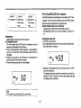
5-4-5 Memory Entry
o
0) ~o€@
\IfO MR MfU
• Simplex/Normal shift
1. Press the VFO/M~ V key to select the VFO mode.
("..VIIMlOCK
II )
1'15.500
@D
0 ("'"II .... )
~I
'©
Q@o~ '"'©I\0
.
DIM
-ns
5. Press the MR/M key within 10 seconds of selecting the Memory
Channel. A beep will sound and the F indicator and the
Memory Channel number will turn on and the transceiver will
change into Memory mode.
2. Select the desired operating frequency, offset, tone, frequency,
etc.(For example 145.500MHz)
18
• CALL Channel
1. Select the desired operating frequency in VFO mode or the
desired memory channel in memory channel mode, and be sure
that PAG/C.Sa not activated.
2. Select the desired offset frequency, tone frequency, etc.
(For example 145.500 MHz in VFO mode)
.
O
VOLa
~I (
(VFOIIMRIIMHz)
v""""
)
LON
5-4-6 Memory Channel Recall
1. Press the MRIM key.
2. Rotate the tuning control or press the microphone UP/ON switches
to select the desired memory channel.
II,PWR )
5-4-7 Memory Shift
~ ~
1'15.500
~.@@
Note CALL channel entry operates only when PAG/C.Sa feature
disabled.
@ij) @o@ ..
This feature copies Memory channel or CALL channel data to the VFO.
This will allow you to recall and alter these frequencies without changing
the actual contents of the memory or CALL channel.
1. Press the MAIM key or CALL key.
2. Press the F key. The F indicator will light.
3. Press the VFO IM~ V key within 10 seconds of pressing the F key.
The F indicator and the Memory or CALL channel indicator will turn
off to signal the data has been successfully transferred to the VFO.
©!\{J;
3. Press the F key. The F indicator and the memory channel
indicator willlight.(For example CH8)
'" ~
0 ~o€@
VOla ( II
~i
(VFOII"RII!.lHz)
1'15.500
}
@ij)
""08
lOW
PWR
)
~~
a
~.~ "©f~
4. Press the CALL key within 10 seconds of pressing the F key. The
F indicator and the Memory Channel number will turn OFF, to
confirm data entry.
•
5-4-8 Memory Channel Clear
1. Enter the memory channel recall mode and select the desired
memory channel.
2. Press the Power Switch to turn off the transceiver.
3. Press and hold the MHz key and turn on the transceiver. Release the
MHz key, the confirmation message will appear on the display.
4. Press MAIM key in 5 seconds, the contents of the selected memory
channel are erased.
c-
19
5-5-2 Hold/Resume Programming
Note Memory channel 1 cannot be cleared.
( II II )
M·V ...
M LOCK
"'"
....
~
O~j\
,
( Lr
The transceiver will stop on a busy channel.
Two type of scan hold/resume have been provided in this transceiver.
• Time operated scan(pause scan)
Scan will resume approximately 3 seconds after stop even if the
station is still present.
• Carrier operated scan (Busy scan)
Scan will hold as long as the signal is present, and will resume
scan 3 seconds after signal drop out.
VOl© ("'"II ...)
~I
tt©
DIN
I
mi!l
08
(Do(CALl) (StiFT) (!§@o@TMf)
so
©7 ~.
a
5-5 SCAN
This transceiver is delivered 'from the factory in the time operated scan
mode. To switch between the two modes use the following procedure.
1. Press the F key for longer than 1 second. The F indicator will flash.
2. Within 10 seconds of pressing the F key. This will toggle the
Scan/Resume mode to carrier operated mode. And B indicator will be
on.
3. To return to time operated mode repeat steps 1 and 2.
When the scan function is turned on the SCAN indicator will light to
indicate the scanning mode.
5-5-1 Scan Operation
The following scan options are available:
1, Band scan
,
Scan proceeds over the entire band (This function operates in the
VFO mode only).
2. Programmable band scan
The scan frequency range is determined by the frequencies stored in
Memory Channels 11 and 12 (This function operates in the VFO
mode only).
3. Memory channel scan
Scan proceeds through those memory channels that actually have
data entered and have not been locked out (This function operates in
the Memory Channel mode only)
5-5-3 Band Scan
1. Press the VFO/M~V key to select the VFO mode,
2. Adjust the sa control to the threshold point.
3. Press and hold the VFO/M~ V key for longer than 1 second.
The SCAN indicator will turn on as a visual reminder then transceiver
is scanning.
r---_ _ Press and hold the VFO/M~ V key for longer than 1 second.
Notes
1.During scanning, the CTCSS/DCS/PAG/C.SQ operation is still
on if any of them is activated,
2.During scanning, transmitting is allowed. When PIT released,
transceiver will wait answering for 4 seconds and then start
scaning again.
20
7. You can reverse the direction by rotating the tuning control
counterclockwise, or by pressing the microphone UP/DN switch.
8. Scan will stop whenever a signal is received (that activates the BUSY
indicator) for a limited time.
9. Press any front panel key except LOW key to stop scanning.
4. You can reverse the direction by rotating the tuning control
counterclockwise, or by pressing the microphone UP/DN switch. The
scan step size depends upon the current step programming.
5. Scan will stop whenever a signal is received (that activates the BUSY
indicator) for a limited time.
6. Press any front panel key except LOW key to stop scanning.
5-5-5 Memory Channel Scan
5-5-4 Programmable Band Scan
1. Adjust the SO control to the threshold point.
2. Press and hold the MAIM key for longer than 1 second. The SCAN
indicator will turn on as a visual reminder the transceiver is scanning.
1. Press the F key for longer than 1 second and then pressing the CALL
key to turn ON/OFF the programming scan mode.
2. THe lower scan limit must be stored in memory channel 11. The
higher scan limit must be stored in memory channel 12.
,----~-
I
Note
If the frequency in memory Channel 11 is equal to or greater
than the frequency stored in Memory channel 12 scan will
proceed over the entire band "Band Scan".
(VFO
IIlolAIIMHz)
IoI-V t.l LOCK
I
(~~"~
II II )
a
0) ~.@)
IoI·V
101 LOCK
VFO/M~V
key for Ionger than
o} ~o@)
0
(i@.~ SO©(!" 0
01101
)
_.
@>
DIM
PWA
)
~~:===~==l
~o@ so©(CO
3.Scan will scan at the current memory channel and proceed
sequentially Le.Ml ~ M2 ~ M3 ~ etc. Only those memory
channels with data entered are scanned.
1'-15.580
'-.:""
@
lOW
Notes
1. The transceiver will not scan if there is only one memory
channel.
2. The transceiver will skip any lock-out channel.
3. The transceiver will scan only the memory channels in which
frequencies have been stored.
secon.
d
© (~II ~I
IiliiiI
© ( II
~l
IiliiiI
1'-I 5.5 00 ""01
3. Adjust the SO control to the threshold point.
4. Press the VFO/M~ V key to select the VFO mode.
5. Select a VFO frequency between the two programmed scan limits.
6. Press and hold the VFO/M~ V key for longer than 1 second.
p ress an d h0 Id the
Press and hold the MR/M key for longer than 1 second.
21
5-6 DUAL-WATCH OPERArlON
4. Scan will stop whenever a signal is received (that activates the BUSY
indicator) for a limited time.
5. Press any front panel key except LOW key to stop scanning.
unwanted Memory Channel during Memory Channel scan.
This function allows you to watch two different frequencies. The
transceiver is capable of following types of Dual-watch operation.
(1) Listen on the dial-frequency and the memory frequency under M1.
(2) Listen on the dial-frequency and one of the memory frequencies.
(3)Listen on the dial-frequency and a memory frequency under
scanning.
1. Select the MAIM key to select the Memory Channel mode.
Information
2. Select the Memory Channel that you wish to skip by using the Tuning
• The word "DUAL" is indicated on the display during Dual-watch
operation.
• The dial-frequency can be changed during dual-watch operation.
• During dual-watch operation, the Transceiver listens on a memory
frequency once every three seconds and instantaneously displays
its frequency.
• Dual-watch operation pauses while the memory frequency is being
received.
• When a signal is received on the dial-frequency during dual-watch
operation, the signal will be heard interruptedly as the transceiver
leave the dial-frequency once every three seconds.
• Rotate the squelch control full counterclockwise to pause the
Dual-watch operation with the memory frequency to listen.
• Press the VFO/MR key will release the Dual-watch mode.
5-5-6 Memory Channel Lockout
The Memory Channel Lockout function allows you to temporarily skip
control or the microphone UP/ON switches.
3. Press the F key for longer than 1 second. The F indicator will flash.
Within 10 seconds of pressing the F key press the MAIM key. A "SKP"
will appear to the left of the Memory Channel number. This indicates
the Memory Channel will be skipped during the Memory Channel
scan operation.
VFO MR t.IHz
( II II )
M·V
'" LOCK
1Lf 5.S 00
NOTES:
(1) During dual-watch operation, transmission is only available at the
dial-frequency.
(2) Press the PIT button to transmit.The dial-frequency is displayed
and you can transmit at the dial-frequency. Release the PTT
button toretum to dual-watch.
(3) When a signal is received at the memory frequency, release the
dual-watch operation and recall the memory frequency for
communication.
(4) During dual-watch operation, the CTCSS/DCS/PAG/C.SQ operation
is still on if any of them is activated.
Press the key tor longer than 1 second.
4. Repeat steps 2 and 3 to lock out any other Memory Channel that you
want to skip.
5. To cancel the lockout, select the desired Memory Channel as
described in step 1,2, and 3 above.
The "SKP" will go out. The Memory Channel will now be scanned
normally.
22
5-6·1 Dual-watch on the dial-frequency and the
memory frequency under CH1.
1. Press the VFO/M~ V key to select the VFO mode.
2. Press the F key momentarily. The F indicator should light in the
display.
3. Press the TONE/DUAL key within 10 seconds of pressing the F key. A
"DUAL" will appear on the display to indicate the Dual-watch
operation.
5-6-3 Dual-watch on the dial-frequency and a
memory frequency under scanning in
sequence
1. Press and hold the MAIM key for longer than 1 second. The SCAN
indicator will turn on as a visual reminder the transceiver is scanning.
r----
5-6-2 Dual-watch on the dial-frequency and a
memory frequency.(or call frequency)
VFO
UI
M-Y
M LOCK
MHz
(1111)
1. Recall a memory frequency you wish to use in the dual-watch
function.
2. Press the F key momentarily. The F indicator should light in the
display.
3. Press the TONE/DUAL key within 10 seconds of pressing the F key. A
"DUAL" will appear on the display to indicate the Dual-watch
operation.
Press and hold the MAIM key for longer than 1 second
VOl© (
~
/'
WI.
l~S.SOO
~IOl
LOW
DIM
II PWR )
~.~
AL\;;'@@)~'~ "'~\Q
2. Press the PWR switch to turn OFF the transceiver.
3. Press and hold the TONE/DUAL key and turn on the PWR switch.
4. The display will alternately indicate the dial frequency and a selected
memory frequency.
4. Release the TONE/DUAL key, A "DUAL" will appear on the display to
indicate the Dual-watch operation.
The display will sequentially indicate the dial-frequency and the
memory frequencies under scanning one by one.
23
2. Press the F key for longer than 1 second. The F indicator will begin to
flash. Press the VFO/M. V key within 10 seconds of pressing the F
key. The current offset frequency will be shown on the display.
5-7 REPEATER OPERATION
5-7-1 Transmitter Offset
All radio repeaters utilize a separate receive and transmit frequency.
The receive frequency may be either above or below that of the transmit
frequency. The initial offset frequency is shown as below:
AR-147
AR·247
3. Rotate the tuning control or press the microphone UPJDN switches to
select the desired offset frequency.
4. Press the VFO/M.V key to select the VFO mode.
AR-447
+
+600kHz +1.6MHz
+SMHz
-
-600kHz
-5MHz
-1.6MHz
5-7-2 Automatic Repeater Offset
This function automatically selects an appropriate offset direction and
offset frequency according to the operating frequency that you select.
The transceiver is programmed for offset direction as shown below.
North America Version
Offset Feature
145.1
To select the desired transmitter offset feature press the SHFT/REV key.
Each time you press the key the transceiver will advance from one
I
145.6
feature to the next.
No indicator
(SilPlex)
-+ "_"
II
T." -+ "+" "T." -+ "_" "+" "T."
(automatic repeater
I
145.5
146.0
~I----'I
-
146.4
+ I
146.6
147.0
I
147.4
147.6
148
I
I
I
I +
VHF
.
145.8
European Version
In the automatic repeater offset mode, when the operating frequency
offse~
falls in the simplex band, the indicators
II
-
"
and
When in minus offset direction band, the indicator
To select the desired offset frequency use the following procedures:
u
+ will light on still.
II -
II
u
flashes. When in
plus offset direction band. the indicator II + II flashes also.
1. Press the VFO/M. V key to select the VFO mode.
24
Repeater Access Tone Selection
Note
The offset frequency and automatic repeater band could be
programmable by factory or dealer/service center,
1. Press the F key for longer than 1 second when the transceiver not in
CrCSS/DCS mode, then press the TONE/DUAL key within 10
seconds. The current repeater access tonewill showon thedisplay.
2. Rotate the tuning control or press the microphone UP/ON switches to
select the desired repeater access tone(1450,1750 or 2100Hz)
3. Press anyfrontpanel key to return to the normal display.
5-7-3 Reverse Function
Some repeaters utilize a " Reverse Pair ", i,e, the transmit/receive
'frequencies are exactly the reverse of another repeater. For example
repeater A uses 146.000 for a transmit frequency (INPUT) and 146.000
for a receiver frequency (OUTPUl). Repeater B might use 146.00 for a
receiver frequency. It would be inconvenient to have to reprogram the
transceiver each timeyou usethese repeaters.
Press F keymomentarily. The F indicator should lightin the display.
Press the SHFT/REV key within 10 seconds of pressing the F key.
The REVfunction is active.
To return to normal press the SHFT/REV key again. The REV indicator
will be turned off.
This function is also useful to check the input frequency of the repeater
so that you can determine if you are within range for simplex
communications.
5-7-5 CTCSS Tone Selection
1. Press the F key for longer than 1 second when the transceiver in
CTCSS mode. The F indicator will begin to flash. Press the
TONE/DUAL keywithin 10 seconds of pressing the F key. Thecurrent
CTCSS tonefrequency will showon the display.
~~~[
<a.1I.~[,
O},
[ . 88.'S
CF)o@ID
@,
[© >11
~~-
)
~.6i@ ©I~©
L - Pressthe key for longer than 1 second.
5-7-4 Tone Operation
Some repeaters require the use of a control signal to activate the
repeater. Several different methods are currently in use.
Sub-audible tones are sometimes used. The transceiver provides two
types of subaudible tone, CTeSS and DCS. There are 50 selectable
CTCSS tonesand 106selectable DCS codes for users.
A repeater access tone is also used in transmit. Press and hold the PIT
key to transmit, then press the microphone CALL key will generate a
repeater access tone.During the repeater access tone being transmitted,
the CrCSS/DCS sub-audible tone is muted.
2. Rotate theTuning control or press the microphone UP/ON switches to
select the desired crcss tonefrequency.
3. Press anyfront panel keyto return to the normal frequency display.
25
2. Rotate the tuning control or press microphone UP/DN switches
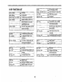
CTCSS TONE FREQUENCY(Hz)
67.0
103.5
159.8
199.5
69.3
107.2
162.2
203.5
71.9
110.9
165.5
206.5
74.4
114.8
167.9
210.7
77.0
118.8
171.3
218.1
79.7
123.0
173.8
225.7
82.5
127.3
177.3
229.1
85.4
131.8
179.9
233.6
88.5
136.5
183.5
241.8
91.5
141.3
186.2
250.3
94.8
146.2
189.9
254.1
97.4
151.4
192.8
100.0
156.7
196.6
select the desired DCS code.
3. Press any front panel key to the normal display.
DCS CODE TABLE(The bracketed code is inverse code)
017
023
025
026
031
032
036
043
047
050
051
053
054
065
071
072
073
074
114
115
116
122
125
131
132
134
143
145
5-7-6 DeS Code Selection
1. Press the F key for longer than 1 second when the transceiver in
DCS mode, then press the TONE/DUAL key within 10 seconds. The
current DCS code will show on the display.
(VFOIIMRIIMHJ)
·" ·~
t
~I (
VOLa
LOW
II PWR )
~
O~\ ~o@ID ~ @)o~ SQ©f~{J
m
d
2b3
'1::3
26
(050)
(047)
(244)
(464)
(627)
(051)
(172)
(445)
(023)
(017)
(032)
(452)
(413)
(271)
(306)
(245)
(506)
(174)
(712)
(152)
(754)
(225)
(365)
(364)
(546)
(223)
(412)
(274)
152
155
156
162
165
172
174
205
212
223
225
226
243
244
245
246
251
·252
255
261
263
265
266
271
274
306
311
315
(115)
(731)
(265)
(503)
(251)
(036)
(074)
(263)
(356)
(134)
(122)
(411 )
(351)
(025)
(072)
(523)
(165)
(462)
(446)
(732)
(205)
(156)
(454)
(065)
(145)
(071 )
(664)
(423)
325
331
332
343
346
351
356
364
365
371
411
412
413
423
431
432
445
446
452
454
455
462
464
465
466
503
506
516
(526)
(465)
(455)
(532)
(612)
(243)
(212)
(131 )
(125)
(734)
(226)
(143)
(054)
(315)
(723)
(516)
(043)
(255)
(053)
(266)
(332)
(252)
(026)
(331)
(662)
(162)
(073)
(432)
523
526
532
546
565
606
612
624
627
631
632
654
662
664
703
712
723
731
732
734
743
754
(246)
(325)
(343)
(132)
(703)
(631 )
(346)
(632)
(031)
(606)
(624)
(743)
(466)
(311 )
(565)
(114)
(431)
(155)
(261 )
(371 )
(654)
(116)
DCS Code Polarity Selection
CTCSS Tone/DCS Code Scan
Because DCS code is a 23-bits continuous string of logic 1 and 0. when
When useing CTCSS/DCS encoding and decoding function, you can
have the transceiver scan through the tones or codes to determine
which one is present on a received signal.During crcss TONE/DCS
scan, the PAG/C.SOfeature is disabled.
1. Let the transceiver enter CrCSS/DCS encoding and decoding
mode.
2. Press F key longer than 1 second, then press TONE key longer then
1 second within 10 seconds. The CTCSS TONE/DCS CODE scan
starts and the SCAN indicator is illustrated on the display.
3. CTCSS TONE/DCS CODE scan can activate only when the carrier
exits in current channel, and stop when the scanned tone/code IS
received.The scanned crcss TONE/DCS CODE will be illustrated
on the display.
4. Press any front panel key to return to the normal display, and the
transceiver exits the CTCSS TONE/DCS CODE scan mode.As
5-7-5/5-7-6 described, you could save the scanned crcss
TONE/DCS CODE in memory.
the DCS signal through the Tx or Rx path, the polarity of the DCS signal
changes probably on other transceivers. The polarity-inversed DCS
signal is just mapping to a specified DCS code as listed in the DCS code
table.
In the DCS encoding/decoding mode, in order to avoid the confusion of
signal polarity, the DCS encoding/decoding polarity could be changed.
1. Press the F key longer than 1 second when the transceiver in DCS
mode, then press the SHFT/REV key longer than 1 second within 10
seconds. The current DCS signal polarity will show on the display.
2. Rotate the tuning control or press the microphone UP/ON switches to
select the desired polarity.
3. Press any front panel key to return to the normal display.
5-8 CTCSS/DCS Feature Selection
Note
If you press the PTr key to transmit when the sub-audible signal
scanned, this scanned signal will be saved to memory
automatically.
When CTCSS/DCS function has been activated, the radio will not open
squelch until the proper tone is received.
Press the TONE/DUAL key and select the desired Tone mode. When
the T indicator appears on the display, the transmitter will transmit the
5-9 C.SQ(CODE Squelch System)
desired tone. When the TSO indicator appears in the display the
transceiver will transmit the desired tone and operate in the Tone
OPERATION[Requires optional DTS147]
Squelch mode, i,e. squelch will not open until the same tone is received
This function allows squelch to be turned on in the receive mode on
reception of a three-digit code matching the C.SO code selected in your
radio.
Once squelch is turn on by reception of a matching code, it operates
normally from then on. If no signal is received for longer than 3 seconds,
squelch is turned off until a matching code is again received.
as a portion of the incoming signal. When no indicator is displayed on
the radio there will be no tone squelch control.
No indicator
A
-+
T
-+
TSQ
-+
DCS T
-+
DCS T.SQ
I
27
,---------------------1
:I ~ roo"
I
L ..L
• Selecting and Storing a code with the DTMF KEY PAD (MIC
147 D)
1. Press the DTMF key twice to light the e,sa indicator.
2. Press the F key, then press the DTMF key while the F indicator is
on in 10 seconds. The C.SO code setting mode will be entered
and the first digit of the code will flash.
3. Then enter a three-digit number on the key pad.
:
LUi
-.J
5-9-1 Selecting and Storing the C,SQ code
C.SO code from 000 through 999 can be selected from the VFO mode
and stored in memory channel.
5-9-2 C.SQ Code Selection
,----------_ ...,---------)
! ~ (-0:00
i
When DTMF unit DTF147 [option] is installed, the initial setting is 000.
.
• Selecting and Storing the C.SQ code with the VFO
1. Press the DTMF key twice to light the c,sa indicator.
2. Press the F key, then press the DTMF key while the F indicator is
on in 10 seconds. The first digit of the C.SO code will flash.
,
L~
© ( II )
~I~-
©
o} ~.@'~ 6@.~ oo@f(C
~~~
CM-VII MIILOCK)
..,.
3. Select the first digit by rotating the liJning control.
4. Press the DTMF key. The first digit is registered and the second
5.
6.
7.
8.
digit begins to flash.
Select the second digit by rotating the tuning control.
Press the DTMF key.The second digit is registered and the third
digit begins to flash.
Select the third digit by rotating the Tuning control.
Press the F key and the complete c.sa code is registered. The
mode returns to the previous one.
,_..
---
_-----_.,,-~
.....
-l
888G
GGGG
8888
5-9-3 Using PAG/C.Sa Function
1. Adjust the Sal control to the threshold point.
2. Press the DTMF key. The C.SO indicator will light. Each time the
DTMF key is pressed, the PAG and c.sa functions will be selected:
28
------'--
:
Notes
1. If a key other than the DTMF key on the front panel is pressed
during operation, code selection mode is canceled.
2. If no action is taken for longer than 10 seconds, code selection
mode is automatically canceled.
3. If the optional DTF 147 is not installed, a Bu-sound will be
generated each time you press the DTMF key.
DIM
... [-0-00
, I \
ee00
8888
5-9-4 Using PAG/C.SQ with a repeater
C.SO:OFF
0
PAGING:OFF
C.SO:OFF
17
PAGING:ON
C.SO:ON
--7
PAGING:OFF
PAG Indicator
C.SO Indicator
lights.
lights.
The PAGlC.Sa signal is transmitted after a short delay if the PIT switch
is pressed. This is to avoid any malfunction due to the PAG/C.Sasignal
beinginterrupted by repeaters with long response time. '
e1i"ansmlt Delay during C.SQ or PAG output
A delayis built in whenthe C.SO or PAG code is sent out.
The initialsetting is 450 ms, and can be changed to 750. 850 or 1000
rns,
r--
eRECEPnON
Squelch will open when the propercode is received.
e TRANSMISSION SPEED
The tone duration for each DTMF digit in transmission could be
selected as 50 (default), 100,150or 200 msec.
1. Press F key then press CALL key for longer than 1 second within 10
seconds. The current OTMF code transmission speed will show on
the display.
2. Rotate the tuning control or the UP/ON key on the microphone to
selectthe desired OTMF Transmission speed.
3. Pressany front panel keyto return to normaldisplay.
• Changing the delay time
1. Turn PAG or C.SO mode on.
2. Tochangedelaytime pressthe F key momentarily and then pressthe
CALL keywithinthe 10 seconds.
,----------------------.
!
I
I
[pM
SP
L~---
ell
L~----
l.f 5 0
i
...J
I
3. Display the desired delay time with the tuning control or the UP/DN
keyon the microphone.
The displayed delay time takes effect immediately. If any other key is
pressed or if, after 10 seconds, no key has been pressed, the delay
time setting mode is terminated.
1----------------------1
i
£R
50!...J
I
Note
Voice output is muted during PAG/C.SO code output.
29
,.
5-10 PAGING
The paging function is available when the optional DTMF unit (DTF147)
is installed.
The paging function is useful to call all station a group, a specific station,
Paging operation procedure
or wait for a call from another station by using DTMF (Dual Tone Multi
Frequency) signaling.
Set your Station code
------'1,:---------!
Exampla:When station 2 is called
Tune to frequency of the other station
'1~HZ
------333
~....I-.--'--=--=:..I-~_-.L...ill:..L
/
SlItion 2'.
'od.
?
w---;J
Enter the paging mode
---I
111
Yout code
To call the other
station
'\
To stand by for a
Pager
~?
F.146.680MHz
F;146.1160MHz
Individual code:333
Stlltion 2
Individual code:444
Transmit
Station J
The common group code and individual codes should be determined in
Call
advance. These codes should be from 000 to 999 (3digits), Unlike C.SO
the code of the calling station is displayed on the receiver, so the
receiver can identify the calling station.
When called by a local station, the individual code of the calling station is
displayed. when called by a group code, that group code is displayed.
30
Stand by
3. Set the desired memory (0 to 3 or A) with the tuning control (or key 0
5-10-1 Paging Code Memories
to 3 or A on the microphone with DTMF keypad).
There are five paging code memories.
4. Press the DTMF key. The first digit will flash.
(This operation is not necessary if 'DTMF microphone is used)
Use
PA
Stores your individuallD code in memory.
PO
Automatically stores the calling station's code
during reception. Can temporarily set code for the
station.
(VFOIIMAIIMHz)
lA-V
P1 - P3
M~
OL
Stores group codes and local station codes in
memory.
~
a(
~L,
~PO [~On 0
,"
CDo@J)
@
<f@o@
~
II PWR)
LOW
DIM
"~fQ
97~~
5. Set the desired number with the tuning control and press the DTMF
key (or key 0 to 9 on the microphone with DTMF keypad). The first
digit be set, and the second digit will flash.
5-10-2 Setting the Paging Codes
1. Press the DTMF key to enter the paging mode. The PAG indicator will
light.
2. Press the F key, then press the DTMF key while the F indicator is on.
The code setting mode will be entered and the memory channel
indicator will flash.
6. Set the second and third digits with the tuning control, and press the
DTMFkey.
7. If, after 10 seconds, no key has been pressed, or a key other than
DTMF is pressed, the code will be set.
31
5·10·3 Paging Transmission (Calling)
Your individuallD code is preset in memory A.(Your individual 10 code is
always storedin memory A.)
1. Turn to the predetermined frequency.
For example. the following groups communicate
with each other.
Predetermined frequency
145.660MHz
Your individual code
Station 1'5 individual code
Station 2'5 indiveiual code
Station 3'5 indiveiual code
Group code
2. Pressthe DTMF key to light the PAG indicator.
~~-
(t.1-VII IIIIILOCK)
111
222
333
444
PO
Station 1 memory
PA 222
P2
PO
P3
789
00
0
3. Pressthe F key, then press the DTMF key while the F indicator is on.
VFO t.IR MHz
( II II )
lA-V
PO
Station 2 memory
PA 333
f©
!JIM
O~L CDo0~) (S~) @E)o(6~F1 ©7 ~
789
Your memory
PA 111
Pl
P2 444
P3 789
,
~1 LJ S.b bO
© ( II ~~
~,'~
O~
:L
789
Station 3 memory
PA 444
PO
P1
L-.
P2
© ( I! ~R )
~,~
VOL
,"
[fWp:AIl 11
(Do(@ @HFT) @!§)a(oTMF)
DIM
oo©(©
~
0
0
4. Select the memory number in which the local station code is stored
usingthe tuning control.
Turn the pagingfunction of the other transceiver on.
789
111
M LOCK
_
Calling all station in the group
32
1. To call all station in the group. select the memory number in which the
group code is stored. In this example, the number is stored in number
P3.
2. Press the PIT key once or press a key other than OTMF to display
the frequency again.
3. Press the PIT switch.
145.660MHz
444·111
\IFQ
NR Wb.
CJIJD
a.-v M LOCK
Gill Li.S.b.b.O
H
1DEIl:JIIJOtlll:JIIJOlZlDIIlOClD n:
145.660MHz
789..111
Gil]
"
Li S.b b 0
",""OIDClIlClIlCIDI:JIIClClO 1][
Local station code 444 and your station 10 code 111 are transmitted. A
OTMF tone sounds is heard during transmitting.
sa
,
,
;
;
5-10-4 Paging Reception (Stand by)
1. Turn to the predetermined frequency.
2. Press the OTMF key to light the PAG indicator.
Group code 789 and your station 10 code 111 are transmitted. A OTMF
tone sounds is heard during transmitting.
Calling a specific station (Example:Cali station 3.)
VFO MR MHz
I
( II II )
",·v
To call a specific station (for example, station 3), use the following
procedure:
1. Select the memory in which the local station code is stored (in this
example, select memory p2.) or Enter the individual code of the local
station in memory O.
2. Press a key other than OTMF key to display the frequency again.
3. Press the PIT switch.
M LOCK
""'1 'i S.b b0
0) ~o@ID
@HFD
~I
© ("",~II ,~ )
~,~ '"f£©
Stand by with individual code (Example: Stand by for station 3.)
33
i
I '
If the local station code can not be decoded,
display.
3. When called with your station ID code, the memory number
automatically changes to O. The 10 code of the number 3 is displayed.
:
C
1 _
t
!t------~------!
." ", POLr U, LJ, U,
!) ~~,
I
L~
.
I
I
I
L~
II
~
Flashing
I
Stand by with group code
I
__..
Err " appears on the
r------- ---------------1
I~PoErr
!
local station code
Flashing
II
~
1. When a call is received with the group code, the squelches of all the
members of the group are opened to enable reception.
When you are called with the group code, the common group code
and its memory channel number are displayed.
4. The squelch is opened.
5. The individual code of the calling station is stored in memory O.
Press the PIT switch to respond to the calling station.
(Example:Group code 789 is stored in channel3.)
Group code
~
y
,.~--~-------~---------~
J
r---t-.~.
145.660MHz
444 * 111
Flashing:
i---------------------l
! ~ ,~5.6 60
'--_4
I H
I
mmDrnD~D~ornD~DOOTX
L~
\
p3 L,.,• B9
,
I:
_.J
!
--/I
•
2. When the P'Tl switch is pressed, group code 789 (as displayed) and
your station 10 code are transmitted, You can participate in the group-,
round table.
3. After the remote station has been called, cancel paging mode.
Communication can be performed more efficiently.
When the transmission ends, the frequency will be displayed again. After
the local station has been contacted, cancel paging mode.
Communication can be performed more efficiently.
34
~---------_._----------
I
5-10-5 Code Lockout
5~11-1 Setting the CODE decoding mode
1, Press the DTMF key to return to normal mode.(turn off the PAG,
If an individual code is stored in P1, P2 or P3, reception is enabled when
the codes match, even if one local station communicates with another.
To use memories P1 to P3 for transmission only, lock out the memories.
When you are communicating with two or more groups having the same
frequency, lock out the group code with which stand by is temporarily
stopped.
• Paging memory lockout
1. Enter the code setting mode and display the number (except
memory 0 and A) to be locked out using the tuning control.
2. Press the M RIM key.
SKP mark lights and the memory is locked out.
C.SO)
2. Press the F key. The F indicator will light.
3. Press the DTMF key within 10 seconds. It will enter into the DTMF
code decoding mode.
The left 2 small digits represents the position no. of the first decoded
DTMF code displayed on the right of LCD.
[ The right 4 big digits represents the lasteddecoded DTMF codes,
r---------=1------------~
II
r
'-------+'-- ,
,
L__
r-----~---~-----------l
,
,
L~
rsm
It \.
.
~
I
~
~Position No. is 1
'I
I
~
4. You can rotate the tuning control or press the microphone UP/DN
switches to select the desired DTMF code position.
,---------------------,
'3 n n n n
'UUUU
3. To cancel, repeat step 1 and 2.
5-~ 1
'__
I
~
I
nnnn
UUUU
L
I
i ~P;3~( 189
f
I
""""
DTMF CODE DECODING FUNCTION
I
The DTMF Code Decoding Function is available when the optional
DTMF UNIT (DTF147) is installed.
The Decoding Function is useful to display the receiving DTMF signal
on the LCD with 16 Digits Maximum.
I
I
II
I
I
t
I
L--L----r-------
I
.-J
position No. is 13
35
I
1.
i
1
J
Ii
!ti
DTMF Autodial Memory Setting
5. Or you can press the MHzlLOCK or the microphone MHz key to
clear the decoded of DTMF codes.
When the OTMF Autodialer operation turn on, the display will show as
follows.(Autodiai Memory 1, empty}
vro
MA MHz
( II II )
".-"
M LOCK
0)
6. Press VFO/M~Vor MAIM key to return to
the normal frequency mode.
I!l
L
1
I
"":01:·sa
"
I'
CDo(CAlL) @i) 6@o@j,f)
0
-©i.\ 0
]~~
©ULJ
DIM
I
.
1. Rotate the tuning control or press microphone UP/ON key to
select the desired autodial memory.
2. Press the MHz key, then the DTMF sequence is reset. key the 16
digits on the microphone to set the desired number.
3. Press the DTMF key, with rotating tuning control or pressing the
UP/ON key on microphone, you can check the DTMF sequence
alternatively.
4. Press any other front panel key, the transceiver will return to
normal display.
5-11-2 Store the CODe Memory
You can keep the decoded code even when you power-on next time if
necessary.
The procedure is :
Press MR/M key to store the code and a long BI-sound will be
generated.
5-12 DTMF AUTODIALER OPERATION
The DTMF Autodialer Operation is available when the optional OTMF
unit (DTF147) is installed. DTMF Autodialer memories could be used for
remote DTMF control sequence or telephone numbers for repeater or
personal autopatch systems.
. .
9 autodial memories store DTMF tone sequences of up to 16 digits
each.
Press the F key and than press DTMF key for longer than 1 second
within 10 seconds, the DTMF Autodialer operation will switch between
ON and OFF indicated by the telephone icon on the display.
Send DTMF Autodial Sequence
1. Turn the transceiver to OTMF autodialer operation.
2. Press the PTI key, the transceiver goes to transmission mode.
3. In transmission mode, press the VFO key on microphone.
The display will show the current autodial memory number and the
first 4 DTMF codes.
4. Press the UP/ON key on microphone to select the desired autodial
memory, then press the VFO key on microphone again, the OTMF
sequence will be sent out .
36
J:
1. To turn the APO function off and on, press the F key for longer than 1
. second, then MHz/LOCK key within 10 seconds. The APO indicator
lights.
2. If, after the 30 minutes in inactive receive mode, no key has been
pressed, the APO indicator flashes and a beep sounds. After that, all
the functions are disabled, and the transceiver enters the automatic
power-off state.
5-13 DTNIF REDIALER OPERATION.
The DTMF Redialer Operation is available when the optional DTMF unit
(DTF147) is installed and the DTMF Autodialer operation is disabled
(the telephone icon disappears on display).
The DTMF sequence sent last time in transmission will be sent again by
activating the DTMF Redialer operation.
1.Turn the transceiver to leave DTMF Autodialer operation (the
telephone icon will disappear on display).
2. Press the PIT key, the transceiver goes to transmission mode ..
3. In transmission mode, press the VFO key on microphone, the DTMF
sequence sent during last transmission will be sent again.
;
,I'
';
5-14 KEYPAD DIRECT FREQUENCY ENTRY
)
.'
.'
i cl
The operating frequency could be selected by entering numbers directly
from DTMF microphone when the optional DTMF unit DTF147 is
installed.
1. Press VFO key to enter VFO mode.
2. Press MHz key to start 1 MHz step frequency tuning.
3. Use the microphone keypad to enter the desired frequency.
Enter the digits in order from the most significant digit down to the least
significant one.
4. If the number entered is other than 0 - 9, the bu-sound is generated,
and the number is inhibited to be entered. The out-of -band entered
frequency is also inhibited.
5. The entered frequency will be automatically modified for the least
significant digits to match the current frequency step.
1
;
1
3. To leave the automatic power-off state, turn the power switch off and
on again.
Note
A small current flows during the automatically power off state. If
the transceiver is not going to be used, be sure to switch the
power off.
5-15DIM(Dimmer)
The intensity of illumination can be set to be one of four levels.
1. Press the F key, then press the LOW/DIM key while the F indicator
lights.
,---------------------1
5-14 APO (Automatic Power Off)
•
The automatic power-off function turns the power off automatically if you
forget to turn off your radio.
The initial setting is OFF.
!
,
L~
37
I
d-2
.
i
_.J
I
1
I
! .,
i
i
5-17 LOCK
2. Select the desired value with the tuning control or the UP/ON key on
the microphone.
3. If, after 10 seconds, no key has been pressed, the displayed level is
set and the original frequency is redisplayed.
There are two types of lock functions.
CD Microphone key lock
When the switch on the rear of the microphone is set to the LOCK
position, all the microphone keys except the PIT key are disabled.
5-16 BEEP
The beep can be turned on and off.
Press the F key for longer than 1 second, then press the DTMF key
while the Findicator is flashing.
Each time this is done, the beep is turned on and off.
@ (~II
~,
(~.,.~
II II )
M-V M LOCK
lfmll.j
5.S 0 0
O}m
o @0
1@J
DIM
)
~o@) "'©(©;
@LOCK
The panel keys (except F and MHz/LOCK and LOW key) and the
tuning control are disabled. However, the microphone function works,
Press the F key, then press the MHz/LOCK key within 10 seconds.
The LOCK indicator lights.
Press the key for longer than 1 secon d.
r- --- --- ..
I
i
I
L~
-------------~
LDCK
Ilf 5.5 00
I
j
__.J
To release the lock, press the F key again, then press the MHz/LOCK
key within 10 seconds.
38
._...
-.~--~_.-,----.-_
.. ...
_-~
,.~_
...-
--
5-18 CHANNEL DISPLAY
5-18-2 Normal frequency display mode
The frequency display can be changed to channel number display.
CH01 is memory channel 1,CH02 is memory channel 2, etc.
Performs the procedures 2,3,4,5 as indicated in 5-18-1 will return to the
normal frequency display mode.
r------- ---------------1
! l'i S.C' ... 0 MOl i
5-18-1 Channel display mode
1. Press the MR/M key to select the Memory channel mode.
2. Turn OFF the Transceiver by pressing the POWER switch.
3. Press both the PTT and CALL key of microphone, press the
MHz/LOCK and hold these 3 keys depressed while turn ON the
transceiver.
4. The LCD will display" PASS to indicate entering into the CH mode
successfully.
I
L~
II
5-19 AM RECEPTION(AR-147 option only)
When the AM RECEPTION option is installed in the AR-147, it is able to
receive AM signals within the frequency range of 118.000 to 135.995
MHz (Air Band).
1. Turn the transceiver to VFO display mode.
2. Press the MHz key for longer than 1 second. The LCD will display IlAIl
to indicate it is in the AM RECEPTION mode. Transmitting is not
allowed whilst in this mode.
3. Press the MHz key for longer than 1 second again, it returns the
transceiver to normal FM mode.
,----------------------1
!
PRSS
I
L~
!
1
...J
5. Turn OFF the power switch and then turn on the power. It will the CH
mode display on LCD.
[----------------------1
I
i
I
I
L~
I
rH-"'
U'
L
~
i
I
I
__.J
39
6 KEY FUNCTION LIST
-+
(1)VFO + PWR/ON
(2)MR t PWRJON
~
(3}MHztPTT+MIC CALL+PWRJON -+
(4)MHZ + PWRION
-+
(5)TONE + PWR/ON
-+
(6)LOWIDIM
(7)F + LOW/DIM
-+
-+
(8)F-l Sec + LOW/DIM
-+
(9)VFO lSec
(10)F + VFO
-+
-+
(11}F-1 Sec t VFO
-+
(12)MR-l Sec
(13}F t MR
(14)F-1 Sec + MR
-+
-+
~
(15)MHz
(16)MHz + MIC DIGITAL KEY 0·9
(17)F + MHz
(18)F-1Sec + MHz
VFO RESET
SYSTEM RESET
CHANNEL DISPLAY MODE ON/OFF
MEMORY CHANNEL CLEAR IFTHE
MR KEY PRESSED IN 5SECONDS
UNDER MEMORY MODE
DUAL WATCH WITH MEMORY SCAN IN
MEMORY SCAN MODE
TX POWER LEVEL SETIING (H/M/L)
ILLUMINATION INTENSITY LEVEL
SETTING(1-4)
TOT (TIME OUT TIMER) ON/OFF AND
SETIING(1/3/S/10/30 Minutes)
VFO SCAN
CALUMR DATA TRANSFERRED TO VFC
CHANNEL
TX OFFSET FREQ SETIING
40
-+
~
MHz FREQUENCY TUNING
ENTER FREQUENCY FROM KEYPAD
PANEL KEYLOCK ON/OFF
APO ON/OFF
(19)F + CALL
-+
(A) SAVE DATA TO CALL CHANNEL
IF NOT IN PAG/C.Sa MODE
(8) DTMF TX DELAY TIME SEn-ING IN
PAG/e.Sa MODE
(20)F + CALL 1Sec
4
!(21)F-1Sec + CALL
4
DTMF SPEED SETIING IN PAG/
C.SO MODE
PROGRAMMABLE BAND SCAN ON/OFF
(22)F + F
(23)F-l Sec t F
-+
-+
(24)F + SHFT
(25)F~1Sec + SHFT
-+
(26)F-1 Sec + SHFT-1 Sec
MEMORY SCAN
SAVE DATA TO MEMORY CHANNEL
MEMORY CHANNEL SKIP ON/OFF
-+
-+
PANEL LED OFF
PAUSE/BUSY SCAN
REV ON/OFF
~ CHANNEL STEP SETTING
(5/10/12.5/20/25/50 KHz)
4 Des TX/AX POLARITY SETTING IF IN Des MODE
(27)F +TONE
(28)F-1 Sec + TONE
(29)F-1 Sec +TONE·1 Sec
(30)F +DTMF
~
~
~
~
(31)F + DTMF + MR
~
(32}F + DTMF + MHz
~
(33}F + DTMF • 1Sec
DUAL WATCH
(A) CTCSS CODE SEHING IN
CTCSS MODE (50 CODES)
(8) DCS CODE SETTING IN DCS
MODE (106 CODES)
(C) REPEATER ACCESS TONE
SEHING (1450/1750/2100 Hz)
(A) CTCSS CODE SCAN IN CTCSS
TX+ RXMODE
(B) DCS CODE SCAN IN DCS TX + RX
MODE
-+
DTMF AUTODIALER ON/OFF
DTMF AUTODIAL MEMORY SETTING
(EACH MEMORY COULD CONTAIN 16
DTMF CODES MAXIMUM, WITH 9
INDIVIDUAL MEMORIES)
ROTARY SW OR MIC UP/ON KEY
-+SELECT MEMORY
MHz KEY-+DTMF CODE SETTING
(A) C.SO CODE SETTING IN C.SO
MODE
(B) PAGING CODE SETTING IN PAG
MODE
(C) DTMF CODE DECODING IF NOT
IN PAG/C.SO MODE
SAVING DTMF DECODING CODES TO
EEPROM IFNOT IN PAG/C.SO MODE
CLEAR DTMF DECODING CODES BUFFER
IF NOT IN PAG/C.SO MODE
(34)F -1Sec + DTMF
4
(35)PTT + MIC CALL
(36)PTT + MIC VFO
-+
-+
DTMF KEY-+DTMF CODE VIEW
BEEF ON/OFF
SEND REPEATER ACCESS TONE
(A) DTMF REDIALING IF NOT IN
DTMF AUTODIALER MODE
(8) DTMF AUTODIALING
MIC UP/DN KEY
-+SELECT DTMF AUTODIALER
MEMORY
MIC VFO KEY
-+SEND DTMF CODE
J
41
,.
\
7 MAINTENANCE
7-1 GENERAL INFORMATION
Your transceiver have been factory aligned and tested to specification before shipment. Under normal circumstances the transceiver will operate in
accordance with these operating instructions. All adjustable trimmer and coils in your transceiver have been adjusted at the factory and should only
be readjusted by a qualified technician with proper test equipment. Attempting service or alignment without factory authorization can void the
transceiver's warranty.
When operated properly, the transceiver will provide many years of service without requiring realignment. The information in this section gives some
.
general service procedures which can be accomplished without sophisticated test equipment.
'
7·2 SERVICE
If it ever become necessary to return the equipment to your dealer or service center for repair, pack it in its original box and packing, and include a
full description of the problems involved. Please include your daytime telephone number. You need not return accessory items unless directly related
to the service problem.
Service note:
Dear OM, if you desire to correspond on a technical or operational problem, please make your note short, complete, and to the point, and please
make it readable.
Please list: Model and serial number.
The problem you are having.
Please give sufficient detail for diagnosis. Provide information such as other equipment in the station, meter readings and anything else you feel
might be useful in attempting diagnosis.
Caution:
Do not pack the equipment in crushed newspapers for shipment. Extensive damage may result during shipment.
Note:
1. Record the date of purchase, serial number and dealer from whom purchased.
2. For your own information, retain a written record of any maintenance performed on the unit.
3. When claiming warranty service, please include a photocopy of the bill of sale, or other proof of purchase showing the date of sale.
42
7-3 IN CASE OF DIFFICULTY
The problems described in this table are failures caused, in general, by improper operation or connection of the transceiver, not by detective
components. Check according to the following table.
Symptom
Probable
Corrective action
Indicators do not light and no receiver noise is
heard when the POWER switch is turned on.
1. Bad power cable or connections.
2. Blown power supply fuse.
1. Check cables and connections.
2. Check for the cause of the blown fuse and
replace the fuse.
No sound from the speaker. No signal can be
received.
1. Squelch is closed.
2. CTCSS/DCS/PAG/C.sa is operating.
1. Turn the sa control counterclockwise.
2. Press the TONE/DUAL or DTMF key to turn offthe
CTCSS/DCS or PAG/C.SQ feature.
No transmitter output.
1. Microphone is not plugged in.
2. Poor antenna connection.
1. Plug jack in.
2. Connect antenna securely.
Weak signal cannot be received.
Poor antenna connection.
Connect antenna securely
Display is dark.
1. Power voltage is low.
2. The DIM is selected too dark.
1. Check voltage for 13.8 VDC ±15%.
2. Press the F key and the LOW/DIM key,
select the desired dimmer value.
The lock is on action.
Press the MHz/LOCK key within ten seconds
of pressing the F key.
The display will not change when the tuning
controls rotated or a key is pressed.
43
Instatting accessories
3. Remove the backing from the small cushion provided with the
DTF147 and attach it to the back of the DTF147.
4. Plug the three connectors into the sockets in the units.
5. Attach the cable from DTF147 as shown in Fig.2
CAUTION
Before installation, be sure to disconnect the DC power supply,
or battery, or damage may occur the equipment.
DTMF unit DTF147
1. Remove the 2 screws securing the top cover.
2. Carefully remove the top cover.(Fig. 1)
Fig. 2
Fig. 1
6. Replace the cover and tighten the screws to complete the
installation.
• Installing DTF147
Attach this unit on the top of VCO shield (Fig. 2)
44
~
AD I
Communications
ONE YEAR LIMITED WARRANTY
• ADI Communications Corp. warrants this product against defects in material and workmanship.
• In the unlikely event of any failure due to defect in material or workmanship, occuring within one year of purchase,
this product will be repaired or replaced at our discretion at no charge.
• The defective product should be returned in its original packing and with proof of the date of the original retail
purchase to your dealer for warranty service.
• The warranty does not cover accident, misuse, fire, flood and other Act of God, unauthorized repair or altered serial
numbers.
• Some statutory regulations do not allow for the exclusion or limitation of incidental or consequential damages, nor
allow limitations on how long an implied warranty lasts, therefore the above limitations may not apply to you,
~
AOI
Cornmumcatrons and
J.-Y:)J
are registered trademark of ADI Communications Corporation
NX255A038E