1
OWNER’S AND
OPERATOR’S MANUAL
Sound Proof
Diesel Engine Generator
Table of Contents
1
2
3
4
5
DG150MI
DG250MI
6
7
8
9
10
11
12
13
14
Safety Guidelines
Specifications
2.1 Specification Matrix
2.2 Ambient Condition
Use
Parts
4.1 External View
4.2 Control Panel
Equipment
5.1 Monitor Display
5.2 Gauges
5.3 Fuel Line Changeover Valve
Transportation and installation
6.1 Transportation
6.2 Installation
Connection
7.1 Selecting Cable
7.2 Connecting Cable
7.3 Earth Leakage Relay and Grounding
Initialization and Pre-check
8.1 Checking Engine Oil
8.2 Checking Coolant/Water
8.3 Checking Fan Belt
8.4 Checking Fuel
8.5 Checking Fuel, Engine oil,
and water leakage
8.6 Checking Battery
Operation
9.1 Initializing / Preparation
9.2 During Operation
9.3 Stopping Generator
9.4 Protection Features
9.5 Connecting to External Fuel Tank
Maintenance
Long-term Storage
Troubleshooting
Generator Wiring Diagram
Engine Wiring Diagram
Page
2
5
5
6
6
6
6
7
8
8
11
14
15
15
16
17
17
18
21
23
23
24
26
27
28
28
29
29
30
31
31
32
33
38
39
41
45
CAUTION : Do not operate the Generator, or any other appliance,
before you have read and understood the instructions for use.
-1-
71000-94011
Introduction
Thank you for purchasing Shindaiwa Sound Proof Diesel Engine Generator.
This user manual was created to ensure the safe operation of this equipment. Therefore, the manufacturer of
this equipment strongly recommends that the user follow the instructions herein, to avoid unnecessary
accidents and repairs.
Please operate this equipment after thoroughly reviewing and understanding the contents of this manual.
Please attach this manual, if the equipment will be sub-leased.
Please store this manual near the equipment for easy reference.
Following convention will be used throughout the manual to indicate the degree of
cautions.
Can cause severe injuries or death.
Danger
!
!
Caution
<Caution>
Can cause minor injuries or damage to the equipment or other
properties
Other types of caution
Even some of the items noted in
!
Caution
follow all the safety guidelines.
-2-
may lead to severe injuries. Please read all items and
1
Safety Guidelines
!
Danger
:Suffocation from exhaust fume
Exhaust fume from the engine contains many elements harmful to human. Do not operate this
equipment in poorly ventilated area, such as inside a room or in a tunnel
!
Danger
:Electrical Shock
Do not touch the output terminals during operation.
Be sure to place covers over the output terminals and fasten with fasteners.
Do not insert metal objects (such as pin or wire) into plug-in receptacles.
Do not touch wiring or any electronic parts inside equipment during operation.
Ground the every earth grounding terminal to the earth as set out in the manual.
If even one of all is unconnected by mistake or accident, it will be much more dangerous for human
body than the NO RELAY case, because leaking current inevitably goes through the body.
Even though all the earth terminals of the loads have been grounded to the earth,
the earth grounding terminal and the outer bonnet (canopy) grounding terminal should be
grounded to the earth.
There is always a danger of being electrocuted by short-circuit. Be sure to test generator’s insulation
resistance periodically.
Before connecting or disconnecting a load cable to/from output terminals, always turn a circuit
breaker to OFF position, stop the engine, and remove the engine key. A person performing the
maintenance should always keep the key.
Before performing any equipment check or maintenance, stop the engine, and remove the engine key.
A person performing the maintenance should always keep the key.
!
Danger
:Injuries
Close all doors and place locks during operating this equipment, to avoid injuries by unintentionally
touching cooling fan and fan belt.
!
Caution
:Suffocation from exhaust fume
Do not point the exhaust fume toward pedestrians or building.
-3-
!
Caution
:Injuries to eyes and skin
Battery fluid contains diluted sulfuric acid. Avoid contact with eyes, skin or on clothing. If the acid comes
in contact, especially with eyes, flush with a lot of water, and contact your physician immediately.
!
Caution
:Fire
This equipment uses Diesel Oil as a fuel. When refueling, always stop the engine, and keep away from
fire. Moreover, always wait until the engine cools down before refueling.
Always wipe any drip of Diesel fuel or Lubrication oil. Do not use this equipment when a leak is found.
Repair the equipment before use.
Temperature around muffler and exhaust can get extremely high. Keep any inflammable items (such as
fuel, gas, paint, etc.) away from the equipment.
Battery may emit some combustible gas, so keep it away from fire and sparks.
Always operate this equipment on flat surface and, at least 1 meter away from any objects (wall, box,
etc.).
Do not connect AC output to any indoor wiring.
Always wait until the equipment cools down, before placing any covering materials for storage.
!
Caution
:Burns
Do not open the radiator cap while operating this equipment or immediately after stopping the equipment,
to avoid sustaining burns from hot vapor.
Do not touch the engine and muffler during operation and immediately after stopping the equipment, for
the temperature can reach extremely high.
When checking engine oil or changing oil, always stop the engine, and wait until the engine cools down.
If you open either the oil gauge or the oil filler cap during operation, hot oil may cause some injury.
!
Caution
:Injuries
When lifting the equipment, always use a lift hook.
Do not use Side rope-through, for it may cause equipment to drop.
Always place the equipment on a flat and stable surface, to keep the equipment from sliding.
When starting the engine, turn off the connected equipment and set the circuit breaker to OFF position.
Do not move the equipment during operation.
When performing equipment check and maintenance, always stop the engine.
Do not operate the equipment, if the equipment is being modified or if the parts are removed.
-4-
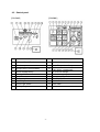
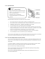
Location of Warning labels
When the warning labels become unreadable or damaged, place new labels on the appropriate location, as
specified in the following figure. When ordering the label, use following part numbers.
1
Safety guidelines
Part Number 19402-00188
2
Suffocation from exhaust fume
Part Number 19402-00161
3
Electrical Shock
Part Number 19402-00163
4
Injuries
Part Number 19402-00167
5
Injuries
Part Number 19402-00162
6
Burns
Part Number 19402-00165
7
Burns
Part Number 19402-00164
8
Fire
Part Number 19402-00166
9
Lift points
Part Number 19401-00153
10
Tie (Sleeper) Marker
Part Number 19401-00207
11
Bonnet Grounding Terminal
Part Number 19401-00206
-5-
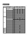
2
Specifications
2.1
Specification Matrix
Name of Generator
DG150MI
Type
Unit
Rated Output
Alternator
Rated Voltage (or the below)
Rated Current (or the below)
Rated Voltage
Rated Current
Frequency
Rated speed
Winding
Power factor
Insulation class
Excitation
No. of poles
Types
Model (Manufacturer)
No. of Cylinders (bore x stroke)
Continuous rated output
Engine
Operation
Device
Protection
Device
Control
Panel
Unit
Rated speed
Displacement
Combustion system
Cooling method
Lubricating method
Starting method
Fuel
Lubricant oil
Fuel tank capacity
Lubricant volume (Full)
Cooling water volume
Starting motor capacity
Charging dynamo capacity
Battery
Volt/Freq/Amp meter
Voltage regulator
Oil pressure, Water temp.
Battery charge
Hour meter
kVA
kW
V
A
V
A
Hz
-1
min
%
mm
kW
PS
-1
min
L
L
L
L
-6-
Blushless, Rotating Field, 3-Phase, 4-Pole,
Synchronous AC Generator
V-A
-
15
20
25
12
16
20
220
200
220
39.4
57.7
65.6
440
400
440
19.7
28.8
32.8
60
50
60
1800
1500
1800
3-phase, 4-wire, Star with neutral
80
F
Self-excitation with AVR
4
Vertical Water-cooled 4-cycle Diesel Engine
3LD1(ISUZU)
AA-4LE1(ISUZU)
3 (83.1 x 92)
4 (85 x 96)
12.6
14.9
19.1
23.5
17.1
20.3
26
32
1500/1800
1.496
2.179
Swirl Chambered
Radiator
Forced lubrication
Electric start
Diesel Fuel (ASTM No. 2-D) or Equivalent
CD class
65
7.4
8.5
5.8
8.6
12 - 1.2
12 - 1.8
12-20
80D26R x 1
75D31R x 1
O
O
O
O
Lamp indication (Engine stops)
Lamp indication
O
O
mm
kg
1390 x 650 x 890
493
V- kW
Dimensions (L x W x H)
Dry weight
DG250MI
12.5
10
200
36.1
400
18
50
1500
1550x 650 x 890
566
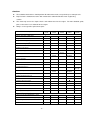
2.2
Ambient Condition
Use the equipment under the following ambient condition. The other condition may cause
trouble, insufficient output power or deterioration of durability.
■ Ambient Temperature: -15ºC ~40ºC
■ Humidity
: less than 80%
■ Altitude
: less than 300m
3 Use
Power source for construction –use equipment, such as submersible pump
Power source for lighting
Power source for electric tools and home appliances
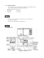
4 Parts
4.1 External view
-7-
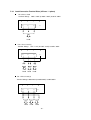
4.2 Control panel
[DG150MI]
No.
[DG250MI]
Name
No.
Name
1
3-Phase Circuit Breaker
11
Monitor Indication Lamp
2
Pilot Lamp
12
3
Single-Phase Circuit Breaker
13
4
5
6
7
8
9
Earth Leakage Relay
Voltage Meter
Amp. Meter
Frequency Meter
Panel Light
Panel Light Switch
14
15
16
17
18
19
Water Temperature Gauge
Tachometer
(Hour Meter incorporated)
Oil Pressure Gauge
Preheat Lamp
Emergency Stop Button
Throttle Handle
Starter Switch
Hour meter
10
Voltage Regulator
-8-
5 Equipment
5.1 Monitor Display
[DG250MI]
[DG150MI]
+
WATER TEMP
OIL PRESS
-
CHARGE
+
AIR FILTER
-
BATTERY LOW LEVEL
FUEL LEVEL
DG250MI is equipped with monitoring function for water/coolant temperature, oil pressure, battery charge, air
filter flow, battery fluid level, and fuel level. DG150MI is equipped with monitoring function for water/coolant
temperature, oil pressure and battery charge.
When the equipment is started under normal condition, Oil Pressure and Battery Charge lamps will flash when
the Starter Switch is turned from STOP to OPERATING, and all lamps will go off, immediately after the engine
is started.
When the abnormality is detected either in water temperature or in oil pressure, the corresponding monitor
lamp will flash, and the automatic shutoff shall be engaged.
When the automatic shutoff is engaged, turn the starter switch to STOP position, then restart the engine.
When the automatic shutoff is engaged next time, check all parts of the corresponding alarm.
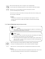
5.1.1 Water Temperature Monitoring Lamp (for temperature High)
!
Danger
: Injuries
Close all doors and place locks during operating this equipment, to avoid injuries by
unintentionally touching cooling fan and fan belt.
!
Caution
: Burns
Do not open the radiator cap while operating this equipment or immediately after
stopping the equipment, to avoid sustaining burns from hot vapor.
Do not touch the engine and muffler during operation and immediately after stopping
the equipment, for the temperature can reach extremely high.
-9-
When the water temperature reaches 110 degrees Celsius during operation,
the water temperature-monitoring lamp will flash, and the automatic shutoff will be engaged.
When this occurs, check the Coolant reservoir tank, and replenish if needed
(refer to 8-2 Checking coolant / water level).
If the water level is normal, check for loose fan belt or possible water leak in the cooling system,
after the engine is cooled down.
<Caution>
If the water level is too low, the sensor cannot detect the water temperature. Be sure
to check the water level in the radiator and the Coolant reservoir tank prior to operating
the equipment.
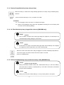
5.1.2 Engine Oil Monitoring Lamp (for oil pressure low)
!
Danger
: Injuries
Close all doors and place locks during operating this equipment, to avoid injuries by
unintentionally touching cooling fan and fan belt.
!
Caution
Do not touch the engine and muffler during operation and immediately after stopping
: Burns
the equipment, for the temperature can reach extremely high.
When checking engine oil or changing oil, always stop the engine, and wait until the
engine cools down. If you open either the oil gauge or the oil filler cap during operation,
hot oil may cause some injury.
2
When the engine oil pressure drops below 0.98 x 100kPa (1kgf/cm ) during operation,
the oil pressure monitoring lamp will flash, and the automatic shutoff will be engaged.
When this occurs, check the engine oil level, and replenish to the maximum level if needed
<Caution>
The engine oil pressure monitor cannot detect the degradation of engine oil itself. Please check
the engine oil periodically, and change if needed (refer to 8-1 Checking Engine Oil).
- 10 -
5.1.3 Battery Charge Monitoring Lamp (charge lamp)
When the battery is unable to be charged during operation, the battery charge-monitoring lamp
will flash.
Check the belt for damages or cut, and replace if needed.
<Caution>
For changing the belt, refer to the User Manual for Engine.
Battery Charge Monitor cannot detect the degradation of battery life nor the battery fluid
level (refer to 8-6 Checking Battery)
5.1.4 Air Filter Monitoring Lamp (clogged filter element) [DG250MI only]
!
Danger
: Injuries
Close all doors and place locks during operating this equipment, to avoid injuries by
unintentionally touching cooling fan and fan belt.
!
Caution
Do not touch the engine and muffler during operation and immediately after stopping
: Burns
the equipment, for the temperature can reach extremely high.
When the air filter element becomes dirty or clogged, the air filter monitoring lamp will flash.
Turn off the engine and clean the filter element or replace if needed.
(refer to 10. Maintenance)
5.1.5 Battery Fluid Monitoring Lamp (insufficient battery fluid) [DG250MI only]
!
Caution
Battery fluid contains diluted sulfuric acid. Avoid contact with eyes, skin or on clothing.
: Injuries to eyes and skin
If the acid comes in contact, especially with eyes, flush with a lot of water, and contact
your physician immediately.
!
Caution
Battery may emit some combustible gas, so keep it away from fire and sparks.
: Fire
- 11 -
When the battery fluid level is low, Battery Fluid Monitoring Lamp will flash.
If the lamp is flashing, quickly add some distilled water. (refer to 8.6 Checking Battery)
5.1.6 Fluid Level Monitoring Lamp [DG250MI only]
!
Caution
: Fire
This equipment uses Diesel fuel as a fuel. When refueling, always stop the engine, and
keep away from fire.
Moreover, always wait until the engine cools down before
refueling.
Always wipe any drip of Diesel fuel or oil. Do not use this equipment when a leak is
found. Repair the equipment before use.
When the fuel level reaches less than 1/4 tank, Fluid Level Monitoring Lamp will flash.
If the lamp is flashing, add fuel.
<Caution>
Just after the engine started, lamp will not flash promptly even in the event of
1/4 tank level fuel, which is not malfanction.
5.2 Gauges
5.2.1 Tachometer [DG250MI only]
Tachometer displays the revolution of engine and the generator.
-1
-1
The frequency of the generator is 50Hz at 1500min and 60Hz at 1800min .
5.2.2 Hour Meter
Hour Meter keeps track of utilization time. Use this meter to schedule your Preventative
Maintenance. Note that the Hour Meter will operate, as long as the start switch is in ON
position, regardless of whether the engine is perating or stopped.
<Caution>
DG250MI incorporates Hour Meter in Tachometer.
- 12 -
5.2.3 Water Temperature Gauge [DG250MI only]
Water Temperature Gauge displays the temperature of engine coolant. Normal temperature
may vary depending on the environment, but it should be between 75 to 90 degree Celsius.
<Caution>
If the temperature exceeds normal value, disconnect the load, idle the engine
-1
at 1000min , and wait until the reading falls to the normal temperature range.
5.2.4 Oil Pressure Gauge [DG250MI only]
Oil Pressure Gauge displays the pressure of engine oil.
Normal pressure may vary
2
depending on the environment, but it should display 2.9 – 4.9 x 100kPa (3-4kgf/cm ).
However, under cold weather, the pressure gauge may display higher reading. Continue
idling until the pressure falls to normal range.
5.2.5 Generator Gauges
5.2.5.1 Voltage Meter
Voltage Meter displays the voltage output (Phase to Phase) from the generator.
5.2.5.2 Amp Meter
Amp Meter displays the electrical (Phase) current output from the generator.
5.2.5.3 Frequency Meter
Frequency meter will display the frequency of the power source
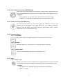
5.2.6 Lamp
5.2.6.1 Preheat Lamp
When the start switch is turned to <Operation or Pre-heating> position, the Preheat Lamp will
be turned. When preheating is completed, preheat lamp turns off and operation can start.
<Caution>
Pre-heating may vary depending on the environment, but it should finishes
in about 1-5 seconds.
- 13 -
2.2.6.2 Pilot Lamp [DG250MI only]
Pilot Lamp indicates whether or not the generator is generating electricity,
when the engine is driving.
5.2.7 Switch
5.2.7.1 Starter Switch
①STOP
When the switch is set to this position, all power will be off. The switch must be
set to this position to remove the key.
②RUN / PREHEAT
The switch must be set to this position during operation. This position is also
used during cold season, to preheat Glow Plug.
<Caution>
Do not leave the switch to this position, while the engine is stopped.
A battery discharges.
③START
This position will allow user to start the engine. When a user release the key,
the setting will automatically return to <Operating / Preheating> position.
5.2.7.2 Panel Light Switch
This switch turns Panel Light to ON and OFF. The switch can only be used when the
Start switch is in OPERATING position.
5.2.7.3 Emergency Stop button [DG250MI only]
This button is used to stop the engine in emergency. Keep pressing the button until the
engine comes to complete halt.
<Caution>
Keep pressing the button until the engine stops in several seconds.
After the engine stops, be sure to return the starter switch to the STOP Position.
5.2.7.4 Circuit Breaker
By turning this circuit breaker switch to ON position, power will be transferred to the
output terminal and to the load side. By turning to OFF position, it will shut down all power
to the load side, preventing overload and short-circuit, and also breaking the earth
leakage.
<Caution>
Do not use this breaker as the ON/OFF switch to the load.
The earth leakage breaking function is for 3-Phase circuit only, not 1-Phase Circuit.
- 14 -
5.2.8 Voltage Regulator and Throttle Handle
5.2.8.1 Voltage Regulator
The dial adjusts output voltage. By turning the dial clockwise, an operator can increase
voltage. By turning the dial counter-clockwise, an operator can decrease voltage.
5.2.8.2 Throttle Handle
This handle controls the engine revolution. By turning the throttle clockwise,
engine speed slows down; turning the handle counter-clockwise increases the
speed. The lock of the handle at the required position (speed) can be done by
turning the Locknut clockwise. Always lock the handle while the generator is
operating. The engine speed can also be changed to high or low by pulling the
handle all the way out or pushing all the way in, while the release button on the
knob pressed.
<Caution>
Always lock the handle while the generator is operating. Failure to do so may result in fluctuation
in frequency (engine speed).
5.2.8.3
Earth Leakage Relay Unit
Sensing the earth leakage current, the unit (relay) send a signal to the 3-phase and the
1-phase breaker to trip-off in order to shut-off the circuit to the terminals (loads).
<Refer to.7-3 Earth Leakage Relay Unit and Grounding>
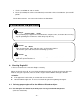
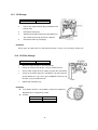
5.3 Fuel Line Changeover Valve (3-way valve)
!
Caution
:Burns
Always stop the engine when performing any work on the fuel line.
Always wipe any drip of Diesel fuel or engine oil. Do not use this equipment, when leak is found. Repair
the equipment before use.
By switching the 3-way valve, you can use fuel from external fuel tank. In this case, the Diesel fuel in the
built-in tank will not be used.
- 15 -
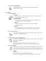
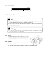
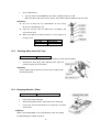
5.3.1 Using fuel from built-in fuel tank
The lever for 3-way valve is set to A when the equipment is
shipped.
In addition, both the external fuel intake and the
external fuel return are safeguarded with PT-3/8 plugs. Do not
remove the plugs, when using the built-in fuel tank.
<Caution>
Always set the lever for 3-way valve back to A position and
cover theexternal fuel intake and return port with the supplied
plugs, after the hoses are removed.
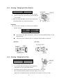
5.3.2 Using fuel from external fuel tank
Connect hoses from the external fuel tank to the external fuel
intake and the external fuel return ports, and set the lever for
3-way valve to B position. You can now supply the fuel from the
external gas tank. For detail instruction, refer to 9-5 Connecting
to the external Fuel tank
6 Transport and Installation
6.1 Transportation
!
Caution
:Injuries
When lifting the equipment, always use a lift hook.
Do not use Side rope-through to attach your lift hook, for it may cause equipment to drop.
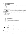
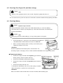
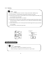
6.1.1 Lifting Equipment
Always use a Lift Hook, when lifting the equipment
for transportation.
- 16 -
6.1.2 Transportation
When transporting this equipment, make sure that the equipment is secured properly with ropes tied
to the Side Rope Through.
<Caution>
Always use extreme care when loading, unloading, and transporting the equipment.
Failure to do so may result in damages and malfunction of the equipment.
6.2 Installation
!
Danger
:Suffocation from exhaust fume
Exhaust fume from the engine contains many elements harmful to human.
Do not operate this
equipment in poorly ventilated area, such as inside a room or in a tunnel
!
Caution
Do not point the exhaust fume toward pedestrians or building.
!
Caution
:Suffocation from exhaust fume
:Fire
Always operate this equipment on flat surface and, at least 1 meter away from any objects (wall, box,
etc.).
Temperature around muffler and exhaust can get extremely high. Keep any inflammable items (such as
fuel, gas, paint, etc.) away from the equipment.
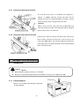
Always set the equipment on hard, flat surface.
Keep the equipment at least 1m from a wall or any obstacles, to allow workable space to access the
control panel and opening of the panel door.
<Caution>
This equipment must be operated on hard and flat surface. Operating under any other conditions
may result in malfunctions.
- 17 -
Do not block the airflow from radiator vent or muffler exhaust. It may result in reduced engine
performance, overheating, or damage to the electrical parts.
Operating in dusty area or salty air (by the ocean), or any other particulate environment may result in
clogged radiator, which may cause overheating, other malfunctions and insulation deterioration.
Use extreme care, frequent checks and maintenance.
7 Connection
7.1 Selecting Cable
Select the cable with proper gauge, based on its allowable amperage and the distance between
the generator and the machinery to be connected.
!
Caution
:Electrical damages
If the load exceeds the allowable amperage, the overheating may damage the cable.
If the cable is either too long or too small a gauge, there will be greater voltage drop to loads, which may
result in reduced performance in the connected loads, malfunction, or damages.
<Caution>
It is recommended to select the proper gauge and length of cable, with consideration of the
maximum 5% marginal drop only for the rated voltage, between the terminals of loads and
generator via the cables.
■ Expedient Expression: the voltage drop of cables
○ 3-Phase 3-Wire
1
Length(m)
x
Voltage Drop (V) =
58
2
Gauge(mm )
x Current (A) x
√3
1-Phase 2-Wire
1
Voltage Drop (V) =
Length(m)
x
58
x Current (A) x 2
2
Gauge(mm )
- 18 -
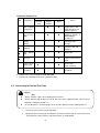
■Selection of cable
(Example) 220V and Voltage Drop 11V
2
3-Phase 3-Wire Cap Tire Cable, Single Core
Length
(Unit: mm )
50m or
below
75m
100m
125m
150m
200m
20A
3.5
5.5
8
8
14
14
40A
8
14
14
14
22
22
60A
14
14
22
22
30
38
80A
14
22
22
30
38
50
Current
(Example) 100V and Voltage Drop 5V
1-Phase 2-Wire Cap Tire Cable, Single Core
2
(Unit: mm )
Length
50m or
below
75m
100m
10A
5.5
5.5
8
20A
8
14
22
30A
14
22
22
Current
7.2 Connecting Cable
!
Danger
:Electrical Shock
Before connecting or disconnecting a load cable from output terminals, always turn a circuit breaker to
OFF position, stop the engine, and remove the engine key. A person performing the maintenance
should always keep the key.
!
Caution
:Fire
Do not connect AC output to any indoor wiring.
<Caution>
Divide loads into 3 circuits proportionally as possible, when using the maximum output power especially,
and connect them to each phase (R,S,T) respectively.
Be careful to limit the current under the rated current per the phase .
The 1-Phase terminals and receptacles output power are originated from the R and T Phase output
powers.
- 19 -
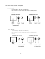
7.2.1 Load Connection Terminal Plate (3-Phase / 1-phase)
■
For 3-Phase Load
Terminal Voltage: 200V / 220V (or 400V / 440V) at 50Hz / 60Hz
R
S
◯
T
◯
O
◯
◯
Load
■ For 1-Phase Load (1)
Terminal Voltage:115V / 127V (or 230V / 254V) at 50Hz / 60Hz
R
S
T
◯
◯
Load
Load
O
◯
◯
Load
■ For 1-Phase Load (2)
Terminal Voltage: 200V/220V (or 400V/440V) at 50Hz/60Hz
R
S
◯
◯
Load
T
◯
Load
O
◯
Load
- 20 -
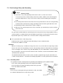
7.2.2 1-Phase Output Terminals & Receptacles
7.2.2.1 200 / 220V
The terminal Voltage: 100V/110V at 50Hz/60Hz only
In the case of no use of 3-Phase output power, refer to the following drawings
and charts.
[DG150MI] (Max 3kVA)
[DG250MI] (Max 6kVA)
○ ○
○ ○
less than
1.5kVA
less than
less than
less than
1.5kVA
3.0kVA
1.5kVA
less than less than
1.5kVA
1.5kVA
less than 1.5kVA
7.2.2.2 400 / 440V
The terminal Voltage: 100V/110V at 50Hz/60Hz only
In the case of no use of 3-Phase output power, refer to the following drawing
and chart.
[DG150MI] (Max 1.2kVA)
○ ○
○ ○
less than
0.6kVA
[DG250MI] (Max 3kVA)
less than less than
0.6kVA
0.6kVA
less than 0.6kVA
- 21 -
less than
1.5kVA
less than
1.5kVA
less than
1.5kVA
less than 1.5kVA
7.3 Earth Leakage Relay and Grounding
!
Danger
:Electrical Shock
Ground the every earth grounding terminal to the earth as set out in the manual.
If even one no of all is unconnected by mistake or accident, it will be much more dangerous
for human body than the –relay case, because leaking current inevitably goes through the
body.
Even though all the bonnets of the loads have been grounded to the earth, the earth grounding
terminal and the outer bonnet (canopy) grounding terminal should be grounded to the earth.
Grounding should be made after the engine is stopped.
Whenever the earth leakage breaker relay is activated, you should always repair the leaking
place first of all.
The generator is provided with the earth leakage breaker relay to detect any leakage produced due to
such the trouble as insulation failure of the load while the generator is running and to cut off the circuit
for protection against any accident such as electrical shock resulting from the trouble.
■The specification of the earth leakage relay;
● Rated Sensitive Current: 30mA (or below) (Grounding resistance: 500Ω or below)
● Sensitive time: Within 0.1second
<Caution>
Different sensitivity relay is available to change. But, in the case, consult with our engineering Section,
because the value each of grounding resistance and grounding condenser will be different accordingly.
In the event bigger value sensitive relay (100, 200, 500mA, etc.) than 30mA will be used in the device,
they are too high in value to prevent from electrical shock. Therefore, install each load with the 30mA
(or below) relay separately.
The detailed information about sensitive current selection is prepared to give by the article No.151.2
In Earth Leakage Breaker – Selection of The Wiring Regulations issued by Japan Electric Association.
7.3.1 Grounding Work
The qualified electrician should perform the grounding of the following 3 points (500Ω or below).
● The earth neutral grounding terminal in the output terminal block
● The Outer Bonnet (Canopy) grounding terminal of the generator
● The Outer Bonnet of the load
<Caution>
In the event you cannot ground the generator to the earth, consult with
the authorized distributor or our engineering section
- 22 -
7.3.2 Operation Check
!
Danger
: Electrical Shock
Before turning the 3-Phase circuit breaker to ON
Position, ensure that the breaker or the switch of
loads are positioned to OFF.
Operate the 3-Phase circuit breaker,
well-communicating with The electrician by the
load side.
Before operating the generator, check always if the device can work.
①
Ensure that the breakers and the switches of load(s) are positioned to OFF.
②
Ensure that the 3-Phase circuit breaker and the 1-Phase circuit breaker are positioned to OFF.
③
④
⑤
「
」
Following the procedure in 9-1 Initializing / Preparation , start an engine.
Turn (Push-up) the 3-Phase circuit breaker (lever) to ON position.
Push the test button (red) in the earth leakage relay unit. When the button is pushed, the earth
leakage indicating lamp turns ON and the 3-Phase circuit breaker is positioned in the middle
⑥
⑦
between ON and OFF positions simultaneously, the device works normally.
Push the reset button. The earth leakage indicating lamp (red) turns OFF subsequently.
Turn (Push-down) the 3-Phase circuit breaker (lever) to OFF position.
In the event you cannot complete every step of the above procedure to the end, the device is out of order.
Consult with our authorized distributor or our engineering section and ask to repair.
7.3.3 The earth leakage breaker relay has activated
In the event the earth leakage breaker relay has activated, the earth leakage indicating lamp Turns ON
and the 3-Phase earth leakage breaker (lever) trips off to be positioned in the middle between ON and
OFF positions.
In the above condition, even though you stop the engine once and start it again, the 3-Phase Circuit
breaker (lever) does not restore to ON or OFF, and the reset button does not function,
because the device keeps detecting current leakage.
Stop the engine promptly and find the leakage point to repair. After repairing the leakage point(s),
proceed with the following restoration steps.
(In the case the earth leakage indicating lamp does not turn to ON simultaneously, the cause is
Over-Load or Short-Circuit.)
- 23 -
① Push the reset button or stop the engine.
② Restore (Push-down) the 3-Phase circuit breaker (lever) and the 1-Phase circuit breaker (lever) to OFF
position.
By the above procedure, you can reset the breakers to ON positions.
8 Initialization and pre-check
!
Danger
:Electrical Shock
・ Injuries
Before performing any equipment check or maintenance, stop the engine, and remove the engine key.
A person performing the maintenance should always keep the key.
!
Caution
:Fire
・Burns
When checking engine, always stop the engine, and keep away from fire.
Wait until the engine cools down, before performing any checks.
!
Caution
:Fire
Always wipe any drip of fuel or oil. Do not use this equipment when a leak is found.
Repair the equipment before use.
8.1 Checking Engine Oil
✳Please refer to the user’s manual for Engine separately
When checking for engine oil, be sure to keep the equipment leveled, and insert the oil gauge all the way.
Prior to starting the equipment, make sure to fill the engine oil to the MAX line through the oil filler.
<Caution>
If the equipment is not leveled, you cannot obtain accurate oil level.
Do not overfill the engine oil. The excessive amount of engine oil may damage the engine.
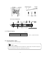
8.1.1 Selecting proper engine oil Use the API class CD grade or higher.
8.1.2 Use the engine oil for Diesel engine with proper viscosity, based on the temperature
(refer to the chart below).
- 24 -
○Viscosity and temperature
SAE20
・20W
SAE40
SAE10W
Temp
(℃)
-30
SAE30
-15
0
SAE10W - 30
15
25
30
・20W - 40
SAE15W - 40
8.1.3 Engine Oil Capacity
(Unit : L)
Lubrication Oil (including the oil in filter)
DG150MI
7.4 (0.4)
DG250MI
8.5 (0.4)
*Value in ( ) shows the oil in filter
8.2 Checking Coolant / Water
✳ Also refer to the User’s Manual for Engine
!
Danger
:Injuries
Before performing any equipment check or maintenance, stop the engine, and remove the engine key.
A person performing the maintenance should always keep the key.
- 25 -
!
Caution
:Burns
Do not open the radiator cap while operating this equipment or immediately after stopping
the equipment, to avoid sustaining burns from hot vapor.
Do not touch the engine and muffler during operation and immediately after stopping
the equipment, for the temperature can reach extremely high.
Check the radiator and coolant reservoir tank for water and add water in case of shortage.
8.2.1 Checking Radiator / Adding water
①
Remove the radiator cap
②
Fill up the radiator up to the top
③
Install the cap back and tighten
<Caution>
With respect to DG150MI, check and add water,
after unscrewing the bolt holding the radiator cap.
8.2.2 Checking Coolant reservoir tank / Adding coolant
①
Check to see if the coolant level is between MIN and MAX line
②
Fill up to the MAX line, if the coolant level is low
<Caution>
Use soft water, such as tap water
If the outside temperature is near freezing,
use Long Life Coolant (LLC)
(30% mixture LLC is used, when shipped from factory)
Use same type of coolant with identical mixture ratio
for the reservoir tank
Mixture ratio of the coolant should be between 30
to 45%, depending on the outside temperature
Replace LLC every 2 years or 400 hours
Mixture ratio (for reference only)
Ambient
temperature
(Celsius)
Mixture ratio
-15
℃
30%
-20
℃
35%
- 26 -
-30
℃
45%
8.2.3 Coolant Capacity
(Unit : L)
Total Coolant Volume (including reservoir tank)
DG150MI
7.4 (0.4)
DG250MI
8.5 (0.4)
*Value in ( ) shows the reservoir tank’s volume
8.3 Checking Fan Belt
✳ Also refer to the user’s manual for Engine separately
!
Danger
:Injuries
Before performing any equipment check or maintenance, stop the engine, and remove the engine
key. A person performing the maintenance should always keep the key.
Close all doors and place locks during operating this equipment, to avoid injuries by unintentionally
touching cooling fan and fan belt.
!
Caution
:Burns
Do not touch the engine and muffler during operation and immediately after stopping the equipment,
for the temperature can reach extremely high.
8.3.1 Tension
Tension should be optimum when the fan belt has 8 to 12mm
slacks, when applying finger pressure (about 98N{approximately
10kgf}) at midpoint between fan pulley and alternator pulley.
8.3.2 Condition
Check for any damage on the fan belt. Replace if necessary.
<Caution>
Refer to the <User’s manual for Engine> for adjusting and replacing of the fan belt.
- 27 -
8.4 Checking Fuel
!
Caution
:Fire
Always wipe any drip of Diesel fuel or oil. Do not use this equipment when a leak is found.
Repair the equipment before use.
Check for the fuel level in the tank. Add if necessary.
<Caution>
Use Diesel fuel, ASTM D975 No.2-D in the
℃
event ambient temperature reaches down to -5 .
Always use the Diesel fuel strainer
Fill the fuel tank slightly less than the FULL tank
Fuel requirements:
、
NOTICE: The fuel injection pump, injector or other parts of the fuel system and
engine can be damaged if you use any fuel or fuel additive other than those
specifically recommended by Isuzu.
Such damage is not our responsibility, and is not covered by the Warranty. To help avoid
fuel system or engine damage, please heed the following:
Some service stations mix used engine oil with diesel fuel. Some manufacturers
of large diesel engines allow this; however, for your diesel engine, do not use the
diesel fuel which has been contaminated with engine oil. Besides causing
engine damage, such fuel can also affect emission control. Before using any
diesel fuel, check with the service station operator to see if the fuel has been
mixed with engine oil.
Do not use any fuel additive. At the time this manual was printed, no other fuel
additive was recommended. (See your authorized dealer to find out if this has
changed.)
The engine is designed to use either Number 1-D or No. 2-D diesel fuel. However, for better fuel
economy, use No. 2-D diesel fuel whenever possible. At temperatures less than –7 ○ C (20○ F), No.2-D
fuel may pose operating problems (see “Cold Weather Operation” which follows). At colder
temperatures, use No.1-D fuel (if available) or use a “winterized” Number 2-D (a blend of No. 1-D and
No. 2-D). This blended fuel is usually called No. 2-D also, but can be used in colder temperatures than
No.2-D fuel which has not been “winterized”. Check with the service station operator to be sure you can
get the properly blended fuel. Note that diesel fuel may foam during a fill-up. This can cause the
automatic pump nozzle to shut off even though your tank is not full.
Notice: Do not use home heating oil or gasoline in your diesel engine; either may
cause engine damage.
- 28 -
8.5 Checking Fuel, Engine Oil, and Water leakage
!
Caution
:Fire
Do not use this equipment when a leak is found. Repair the equipment before use.
Be sure to check for any fuel leak at the hose connection, and oil and coolant leak by opening side doors.
8.6 Checking Battery
!
Caution
:Injuries to eyes and skin
Battery fluid contains diluted sulfuric acid. Avoid contact with eyes, skin or on clothing.
If the acid comes in contact, especially with eyes, flush with a lot of water, and contact your
physician immediately.
!
Caution
:Fire
Battery may emit some combustible gas, so keep it away from fire and sparks.
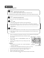
①
Check the fluid level. If the level is near or lower than the MIN level,
add distilled water until the fluid level reaches the MAX limit.
②
Make sure that the battery cables are firmly secured to the posts.
Tighten the clamps if necessary.
<Caution>
Check the hydrometer of the battery fluid. If it falls below 1.23,
the battery requires recharging. Please call our authorized distributor or our engineering section.
■Replacing the battery
①
Remove the clamp and cable from negative (-) post from the
battery. (always remove negative side first)
②
Remove the hold-down clamp from the battery.
③
Remove the clamp and cable from positive (+) post from the
battery.
④
Remove the battery from the seat
*Reinstall the new battery in the reverse order (always install the
cable to the positive (+) post of the new battery first.
<Caution>
Make sure that the removed cable does not come in contact with the battery post.
- 29 -
9 Operation
9.1 Initializing / preparation
!
Danger
:Suffocation from exhaust fume
Exhaust fume from the engine contains many elements harmful to human.
Do not operate this equipment in poorly ventilated area, such as inside a room or in a tunnel .
!
Caution
:Suffocation from exhaust fume
Do not point the exhaust fume toward pedestrians or building.
!
Caution
Temperature around muffler and exhaust can get extremely high.
:Fire
Keep any inflammable items (such as fuel, gas, paint, etc.) away from the equipment.
Always operate this equipment on flat surface and, at least 1 meter away from any objects
(wall, box, etc.).
!
Caution
Always place the equipment on a flat and stable surface, to keep the equipment from sliding.
When starting the engine, turn off the connected equipment and set the circuit breaker to
:Injuries
OFF position.
①
Turn the circuit breaker for single-phase and 3-phase on the control panel to OFF position
②
Press the speed control knob all the way in, while pressing the
release button.
③
Turn the starter switch to <START/PREHEAT> position, and
start the engine.
④
Start the engine promptly, when the pre-heating status lamp
comes OFF.
<Caution>
● Preheating time may vary from 1 to 5 seconds, depending on
the water temperature.
● Do not drive the starter motor for more than 10 seconds successively.
● If you need to restart, wait at least 30 seconds before the retry.
⑤
Release the starter switch, as soon as the engine is started
⑥
Keep the engine idle for at least 10 minutes
⑦
Pull the speed control knob all the way out, while pressing the release button.
- 30 -
And then adjust the speed by speed control knob and adjust to the No-load revolution.
50 Hz
60 Hz
Operation
Operation
No-load revolution
-1
1575 min (52.5 Hz)
-1
1890 min (63.0 Hz)
<Caution>
By adjusting the speed to the above revolutions, the frequency will be 50Hz or 60Hz.
⑧
Lock the Speed Control handle with locknut
<Caution>
Ensure that the speed control handle is surely locked with locknut, otherwise the
frequency (engine revolution) may fluctuate.
⑨
Adjust to the required voltage by adjusting Voltage regulator.
⑩
Turn the circuit breaker to ON position to send power to the load side.
!
Danger
: Electrical Shock ● Injuries
Before turning the circuit breaker to ON position to send power to the load side, always ensure
that any circuit breaker and switch of loads are positioned to OFF.
In the case the generator and the load are away from each other, proceed with the above
steps, communicating well with the other person by the load in order to prevent from
accident.
9.2
During Operation
9.2.1 Post startup check
Make sure that all meters (gauges) and displays are working properly (refer to 5. Equipment)
Check for any unusual vibration or noise
Check for any unusual color from the exhaust. Under normal condition, the exhaust fume has no
color or light bluish color.
<Caution>
If finding out abnormality, consult with the distributor or our engineering section in order to repair,
without using the machine.
- 31 -
9.2.2 Adjustment During operation
Make minor adjustment to voltage and speed using the Speed Control Knob and Voltage
Regulator, by monitoring Tachometer, frequency meter, and voltage meter
■
Vacuuming the air out of the fuelling system in event of no fuel
✳
Refer to the <User’s manual for Engine> separately.
This generator is equipped with automatic vacuuming air feature.
Thus if the engine stops due to running out of fuel, follow the next
steps to vacuum the air out.
①
Add fuel to the fuel tank
②
Loosen the air extracting plug to remove the air out. Tighten the plug, ensuring all the air out.
③
Turn the starter switch to <Operating/Preheating> position. It will take approximately 10
seconds to vacuum the air out.
<Caution>
Ensure that all the air is completely extracted from fuel line, by pushing the speed control knob
all the way out and start the engine.
In the case air is in the fuel line, the engine speed is unstable, and proceed with the vacuuming
steps again.
9.3 Stopping the Generator
①
Turn the switch and the circuit breaker for the load equipment to OFF
②
Turn the circuit breaker for single-phase and 3-phase on the control panel to OFF position
③
Loosen the locknut for the Speed Control knob
④
Press the Speed Control knob all the way in, while pressing Release Button, and let the
engine idle at 1000min
-1
⑤
Keep the engine idle (cooling down) for at least 3 minutes
⑥
Turn the starter switch to STOP position
9.4 Protection Features
This generator is equipped with automatic shutdown feature and display of the location of alarm,
in event of any alarm situation. In event of the automatic shutdown or alarm lamp flashing,
turn off the engine and investigate the alarm.
- 32 -
Protection Feature List
No.
Symptoms
Circuit
Breaker
OFF
Action
Automatic
Engine
Shutoff
Alarm Lamp
Flash
1
High Coolant
temperature
--
○
○
2
Oil pressure
drop
--
○
○
3
Insufficient
battery
charge
--
--
○
4
※
Dirty filter or
clogged
--
--
○
5
※
Low
fluid
--
--
○
6
※
Low fuel
--
--
○
7
Current leaks
to the earth
○
--
○
8
Overload
○
--
--
battery
Cause
Engine coolant
temperature is too
high (default at 110
degrees Celsius)
Engine oil pressure
dropped (default at
0.98x100kPa)
2
(1.0kgf/cm )
When the battery can
no longer hold
charge
When an air filter
becomes dirty and
clogged
When the battery
fluid is low
When the fuel falls
below recommended
level
When current leaks
to the earth
(Only 3-Phase)
When the circuit
overloads
※ indicates the feature incorporated with DG250MI
○ indicates the automatic feature in the both generators
9.5 Connecting to External Fuel Tank
!
Caution
:Fire
Always stop the engine, when working on the fuel line.
Always wipe any drip of Diesel fuel or oil. Do not use this equipment when a leak is found.
Repair the equipment before use.
Ensure that there is no fuel leakage on the fuel line after the fuel line working finished.
①
Turn the lever for 3-way valve to A position
②
Disconnect the P/T-3/8 plugs from both the external fuel intake and an external fuel return,
and connect the hoses from an external fuel tank, as shown below.
- 33 -
③
Turn the lever for 3-way valve to B position.
④
Vacuum out the air from connected hoses. This will allow the use of the fuel from an external
fuel tank.
<Caution>
To vacuum out the air from the fuel line,
refer to <9.2 During Operation> section.
Use always oil-proof hose in 8-10mm
inner diameter as connecting hose.
The fuel level in the external fuel tank should be
0 to 3m higher than the bottom of the generator.
To avoid any leaks from the external fuel intake
and an external fuel return ports,
always turn the lever for 3-way valve to A position.
Use extreme caution when connecting the hoses. If the lever position is not set properly,
the fuel may leak from either the built-in fuel tank or an external fuel tank.
10 Maintenance
!
Danger
:Electrical Shock ● Injuries
Before performing any equipment check or maintenance, stop the engine, and remove the engine key.
A person performing the maintenance should always keep the key.
!
Caution
:Fire ● Burns
When checking engine, always stop the engine, and keep away from fire. Wait until the engine cools
down, before performing any checks.
!
Caution
:Fire
Always wipe any drip of gasoline or oil. Do not use this equipment when a leak is found. Repair the
equipment before use.
To optimize the use of this generator, we recommend the periodical equipment checks and maintenance,
based on following maintenance matrix. Use the hour meter as a guide for the operating time.
- 34 -
<Caution>
The authorized technicians should perform all maintenance work, except for the pre-startup checks.
Request for the maintenance items with ● mark to the authorized dealer or our engineering
section.
This chart only covers the simple checks and maintenance for the engine. For more detailed guide,
please refer to the User’s Manual for the engine.
Always use our genuine replacement parts.
Startup
check
Description
Engine Side
Clean each parts / tightening
Engine oil checks / add oil
st
Engine oil change (1 time at 50 hr mark)
Oil Filter change
st
(1 time at 50 hr mark)
Coolant level check / add coolant
Exhaust color check
○
○
○
○
○
○
Every
200hrs
○
Coolant change
Drain water from fuel filter or replace
Drain excess water and sediments in the
water separator
Drain water from fuel tank
Clean inside fuel tank
○
○
Every
400hrs
Every
500hrs
○
○
or 2 yr.
Clean
○
Replace
○
●
○
Leak check (fuel, oil, and coolant)
Replacing fuel hose
Clean or replace air cleaner element
○
Battery fluid level check
Battery hydrometer check
○
○
Clean
○
●
Radiator Flush Cleaning
Check and adjust engine valve clearance
Compression check
●
Fuel injection nozzle check
Fuel injection timing check
Generator side
Various meter and alarm lamps check
○
Operation check of earth leakage relay
○
Grounding resistance check
○
○
Insulation test
- 35 -
●
or 1 yr.
Replace
○
Fan belt check
Every
1000hrs
●
●
●
10.1 Oil Change
First time
From second time
50 hour mark
Every 200 hours
①
Remove Oil Filler cap
②
Loosen the engine oil drain plug and allow the oil
to drain fully
③
Reinstall the drain plug
④
Add oil from oil filler and fill up to the MAX level.
You should check the oil level on the dipstick
⑤
Reinstall the filler cap hand-tight
<Caution>
For the types of engine oil to use and volume to replace, refer to <8-1 Checking Engine Oil>
10.2 Oil Filter Change
First time
From second time
50 hour mark
Every 400 hours
①
Drain the engine oil fully, as described in 10.1
②
Loosen and remove the oil filter, using an oil filter wrench
③
Smear a little engine oil on the rubber gasket of the new oil filter
④
Screw the new filter into place and tighten it by hand until the
gasket contacts the seat. Then, give it additional 2/3 turn to seat
the filter, using an oil filter wrench
⑤
Add oil and install filler cap
<Caution>
If an oil filter wrench is not available, contact our authorized
distributor or our engineering section..
Oil filter:
Model
DG150MI
DG250MI
ISUZU Part No.
8944567412
8944567411
- 36 -
10.3
Cleaning / Changing Air Filter Element
Clean
Replace
Every 200 hours
Every 500 hours
①
Unscrew the wingnut and remove the filter element
②
Clean or replace the filter element, and reinstall it in
reverse order
※With respect to DG150MI, unfasten clip in cleaner cap
and remove before unscrewing the wingnut.
<Caution>
Clean more frequently, if used in dusty environment
Air filter element:
Model
DG150MI
DG250MI
ISUZU Part No.
8970423170
8971683060
■ If the element has dried contaminants, it may be cleaned by blowing compressed air
from the inside
■ If the element has carbon or grease, it should be replaced with new element.
[DG250MI]
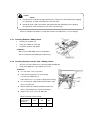
10.4
[DG150MI]
Cleaning / Changing Fuel Filter
Check
Clean
Replace
Prior to Operation
Every 200 hours
Every 500 hours
①
Turn fuel line valve lever to CLOSE
②
Unscrew the ringnut by turning it counterclockwise,
and remove the cup and fuel filter element
③
Discard any dust or water inside the cup, and clean the
filter element by blowing compressed air (or replace, if necessary)
(When you are replacing the filter element, be sure to replace an O-ring as well)
- 37 -
④
Reassemble it back
※ The fuel strainer in DG150MI has the water separating feature as well.
When the float (red) in the strainer comes up by 20mm from the bottom, drain the water
<Caution>
Be sure to check for any contaminants on the O-ring,
whenever reinstalling the cup
Open the fuel line valve to OPEN after assembling, and
check for any leak
When you replace the filter element, be sure to replace an
O-ring as well
Model
DG150MI
DG250MI
10.5
ISUZU Part No.
8943602540
8970713480
Draining Water from Fuel Tank
Drain water
Every 200 hours
①
Unscrew the Fuel drain plug and turn the drain lever on the tank to OPEN
②
Reinstall the drain plug, after draining water fully and
restore the drain lever to CLOSE
<Caution>
Ensure always that the drain lever on the tank is kept CLOSE
after draining water
10.6 Changing Coolant / Water
Replace
Every 2 years or 400 hours
①
Remove the radiator cap
②
Loosen the water drain plug
③
After draining all the water, reinstall the water drain plug
④
Loosen the fastener that holds the reservoir tank, and drain
all the water
<Caution>
With respect to DG150MI, check and add water, after unscrewing
the bolt holding the radiator cap cover
- 38 -
⑤
Install the reservoir tank back, and fill the coolant/water to the MAX level.
⑥
Fill the radiator with coolant/water to the top
⑦
Reinstall the radiator cap
<Caution>
For the types of engine oil to use, refer to
<8-2 Checking Coolant/Water>
11
Long-term Storage
!
Danger
:Electrical Shock ● Injuries
Before performing any equipment check or maintenance, stop the engine, and remove the
engine key. A person performing the maintenance should always keep the key.
!
Caution
:Fire ● Burns
Temperature around muffler and exhaust can get extremely high. Keep any inflammable items
(such as fuel, gas, paint, etc.) away from the equipment.
When checking engine, always stop the engine, and keep away from fire. Wait until the engine
cools down, before performing any checks.
Always wipe any drip of Diesel fuel or oil. Do not use this equipment when a leak is found.
Repair the equipment before use.
11.1 Storage Procedures
If the generator will not be used for more than two months, perform the following maintenance
and storage procedures.
①
Remove battery
②
Change engine oil
③
Drain fuel from fuel tank and fuel filter
④
Clean all parts, cover the generator, and keep it in the storage, away from dust and humidity.
<Caution>
Recharge the removed battery once a month.
Refer to the user’s manual for the care of the engine.
- 39 -
11.2
Stacking
!
Danger
: Injuries
If you have to stack two generators in warehouse, always proceed with the following steps.
Ensure that there is no dent on bonnet, loosing bolt or no bolt in the generators.
Always place the generators on a flat and stable surface, to keep the equipment from sliding, And
to be endurable for the total weight.
When lifting the equipment, always use a lift hook.
Always place ties (sleepers) on the marked points in the lower generator firstly and then stack the
upper generator on it. All the ties should be the same size (dimension) and longer than the width of
the lower generator.
Do not stack more than 2 units. The lower generator should be bigger than the upper generator in
size and weight.
Do not operate the stacking/stacked generators.
12
Troubleshooting
!
Danger
:Electrical Shock
Do not operate the equipment, if the equipment or you are wet.
Before performing any equipment check or maintenance, stop the engine.
- 40 -
!
Caution
!
:Injuries
When performing equipment check and maintenance, always stop the engine.
Caution
:Fire ● Burns
Battery may emit some combustible gas, so keep it away from fire and sparks.
Temperature around muffler and exhaust can get extremely high. Keep any inflammable items
(such as fuel, gas, paint, etc.) away from the equipment.
When checking engine oil or changing oil, always stop the engine, and wait until the engine
cools down. If you open either the oil gauge or the oil filler cap during operation, hot oil may
cause some injury.
Follow the guideline below, when performing any troubleshooting. If you cannot resolve the problems by this
troubleshooting guide, contact the authorized distributor or our engineering section to request the repair.
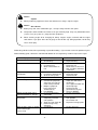
Symptoms
Starter motor does not start
Engine does not start
Engine starts, but stalls
immediately
No AC output
Weak AC output
Possible Cause
Weak battery
Dead battery
Fuel lever to CLOSE
Insufficient fuel
Water contaminants in
fuel
1.
2.
1.
1.
2.
1.
2.
3.
1.
1.
2.
Insufficient oil
Insufficient coolant/water
Air in the fuel system
Circuit breaker is OFF
Wrong frequency
Connected equipment’s
amperage exceeds the
rated value(Overload)
Multiple equipment
being connected
simultaneously
Low SPEED
Uneven load balance
connection
Circuit breaker is not
completely turned to
OFF position
Short-circuit on load side
Earth leakage relay
activated
Overloading
1.
2.
3.
1.
1.
3.
Voltage sharply drops when
connected machines start up
Cannot turn circuit breaker to
ON position
4.
1.
1.
2.
3.
Black or white smoke is coming
out of exhaust pipe
successively.
Corrective Actions
1.
2.
1.
2.
3.
1.
- 41 -
2.
3.
4.
1.
1.
Recharge battery
Replace battery
Fuel lever to OPEN
Replenish fuel
Drain water or clean fuel
tank, fuel filter, and water
sedimenter
Replenish oil
Replenish water
Vacuum out air
Turn circuit breaker to ON
Adjust the frequency to
match the connected
equipment
Use equipment within the
rated amperage
Connect load to
generator one by one
Increase SPEED
Change connection
2.
3.
Push circuit breaker to
OFF position
Check load side
Repair the leakage point
1.
Reduce the load
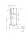
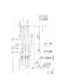
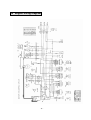
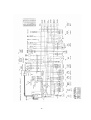
13 Generator Wiring Diagram
- 42 -
- 43 -
- 44 -
- 45 -
14 Engine Wiring Diagram
- 46 -
- 47 -