1
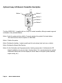
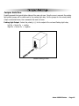
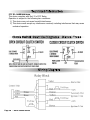
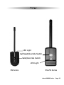
ASTRA 1000RS
SERIES
AUTOMATIC/MANUAL TRANSMISSION
WITH SEPERATE LOCK/UNLOCK BUTTONS
REMOTE START SYSTEM
PRODUCT MANUAL
Limited Lifetime Warranty
This vehicle starting system is warranted to the original purchaser, to be free from defects in
material and workmanship. The manufacturer will repair or replace at its option, and free of
charge for the first twelve (12) months, any part that proves defective in material or workmanship
under normal installation, use, and service, provided the product is returned to the manufacturer
freight prepaid. After the first 12 month warranty period there will be a maximum service charge
of $25.00 per calendar year (if required) for repair and/or replacement of any defective parts.
A copy of the original purchase and installation receipt must accompany any products
returned for warranty service. Warranty is limited to defective parts and/or replacement parts
only and excludes any incidental, and consequential damages connected therewith.
The manufacturer of this theft deterrent system makes no warranty against the theft of the vehicle
or its contents. This warranty is not to be construed as an insurance policy against loss.
WARRANTY OF INSTALLATION LABOR, REMOVAL AND RE-INSTALLATION CHARGES ARE
NOT THE RESPONSIBILITY OF THE MANUFACTURER.
Note: This Warranty is voided if the product was not installed by an
Authorized ScyTek Dealer.
Table of Contents
1.
2.
3.
4.
5.
6.
7.
8.
9.
10.
11.
12.
13.
14.
14.
15.
About Your System . . . . . . . . . . . . . . . . . . . . . . . . . . . . . . . . . . . . . . . . . . . . . . . . . . . .Page 1
Remote Transmitters . . . . . . . . . . . . . . . . . . . . . . . . . . . . . . . . . . . . . . . . . . . . . . . . . . .Page 2
Remote Transmitter Description . . . . . . . . . . . . . . . . . . . . . . . . . . . . . . . . . . . . . . .Page 2
Adding/Replacing Transmitters . . . . . . . . . . . . . . . . . . . . . . . . . . . . . . . . . . . . . . .Page 2
Two Car Operation . . . . . . . . . . . . . . . . . . . . . . . . . . . . . . . . . . . . . . . . . . . . . . . .Page 3
Battery Replacement . . . . . . . . . . . . . . . . . . . . . . . . . . . . . . . . . . . . . . . . . . . . . .Page 3
2-Way LCD Remote Transmitter Description . . . . . . . . . . . . . . . . . . . . . . . . . . . . . .Page 4
LCD Battery Replacement . . . . . . . . . . . . . . . . . . . . . . . . . . . . . . . . . . . . . . . . . . .Page 5
Setting The Time . . . . . . . . . . . . . . . . . . . . . . . . . . . . . . . . . . . . . . . . . . . . . . . . .Page 5
Setting The Alarm Clock . . . . . . . . . . . . . . . . . . . . . . . . . . . . . . . . . . . . . . . . . . . .Page 5
Setting The Automatic Start Or Auto Activation . . . . . . . . . . . . . . . . . . . . . . . . . . . .Page 5
System Confirmation/Transmitter programmable functions . . . . . . . . . . . . . . . . . . Page 6
Visual Indications . . . . . . . . . . . . . . . . . . . . . . . . . . . . . . . . . . . . . . . . . . . . . . . . .Page 7
System Operation . . . . . . . . . . . . . . . . . . . . . . . . . . . . . . . . . . . . . . . . . . . . . . . . . . . . .Page 8
Remote Locking . . . . . . . . . . . . . . . . . . . . . . . . . . . . . . . . . . . . . . . . . . . . . . . . . .Page 8
Remote Unlocking . . . . . . . . . . . . . . . . . . . . . . . . . . . . . . . . . . . . . . . . . . . . . . . .Page 8
Visual Car Finder Mode . . . . . . . . . . . . . . . . . . . . . . . . . . . . . . . . . . . . . . . . . . . . .Page 8
Valet Mode . . . . . . . . . . . . . . . . . . . . . . . . . . . . . . . . . . . . . . . . . . . . . . . . . . . . .Page 8
Remote Start Features . . . . . . . . . . . . . . . . . . . . . . . . . . . . . . . . . . . . . . . . . . . . . . . . .Page 9
Manual/Automatic Transmission Mode . . . . . . . . . . . . . . . . . . . . . . . . . . . . . . . . .Page 9
Remote Starting . . . . . . . . . . . . . . . . . . . . . . . . . . . . . . . . . . . . . . . . . . . . . . . . . .Page 9
Shut Down . . . . . . . . . . . . . . . . . . . . . . . . . . . . . . . . . . . . . . . . . . . . . . . . . . . .Page 10
Quick Stop . . . . . . . . . . . . . . . . . . . . . . . . . . . . . . . . . . . . . . . . . . . . . . . . . . . . .Page 10
Automatic Start Mode . . . . . . . . . . . . . . . . . . . . . . . . . . . . . . . . . . . . . . . . . . . . .Page 10
Extended Features . . . . . . . . . . . . . . . . . . . . . . . . . . . . . . . . . . . . . . . . . . . . . . . . . . .Page 11
Ignition Door Locking . . . . . . . . . . . . . . . . . . . . . . . . . . . . . . . . . . . . . . . . . . . . .Page 11
Ignition Door Unlocking . . . . . . . . . . . . . . . . . . . . . . . . . . . . . . . . . . . . . . . . . . .Page 11
Auxiliary Function Outputs . . . . . . . . . . . . . . . . . . . . . . . . . . . . . . . . . . . . . . . . .Page 11
Turbo Timer Feature . . . . . . . . . . . . . . . . . . . . . . . . . . . . . . . . . . . . . . . . . . . . . .Page 11
“Call” Feature . . . . . . . . . . . . . . . . . . . . . . . . . . . . . . . . . . . . . . . . . . . . . . . . . . .Page 11
System Installation . . . . . . . . . . . . . . . . . . . . . . . . . . . . . . . . . . . . . . . . . . . . . . . . . . .Page 12
Mounting the Control unit . . . . . . . . . . . . . . . . . . . . . . . . . . . . . . . . . . . . . . . . . .Page 12
System Wiring . . . . . . . . . . . . . . . . . . . . . . . . . . . . . . . . . . . . . . . . . . . . . . . . . . . . . .Page 13
5-Pin Starter Harness . . . . . . . . . . . . . . . . . . . . . . . . . . . . . . . . . . . . . . . . . . . .Page 13
16-Pin Main Harness . . . . . . . . . . . . . . . . . . . . . . . . . . . . . . . . . . . . . . . . . . . . . .Page 13
4-Plug-in Connectors . . . . . . . . . . . . . . . . . . . . . . . . . . . . . . . . . . . . . . . . . . . . .Page 14
Starter Diagnostics . . . . . . . . . . . . . . . . . . . . . . . . . . . . . . . . . . . . . . . . . . . . . . . . . . .Page 14
Jumper Settings . . . . . . . . . . . . . . . . . . . . . . . . . . . . . . . . . . . . . . . . . . . . . . . . . . . . .Page 15
Jumper Selection . . . . . . . . . . . . . . . . . . . . . . . . . . . . . . . . . . . . . . . . . . . . . . . .Page 15
System Programming . . . . . . . . . . . . . . . . . . . . . . . . . . . . . . . . . . . . . . . . . . . . .Page 16
Entering System Programming . . . . . . . . . . . . . . . . . . . . . . . . . . . . . . . . . . . . . . .Page 16
Default Reset . . . . . . . . . . . . . . . . . . . . . . . . . . . . . . . . . . . . . . . . . . . . . . . . . . .Page 16
Programmable System Options . . . . . . . . . . . . . . . . . . . . . . . . . . . . . . . . . . . . . .Page 16
Branch Table . . . . . . . . . . . . . . . . . . . . . . . . . . . . . . . . . . . . . . . . . . . . . . . . . . .Page 18
Relay Diagrams . . . . . . . . . . . . . . . . . . . . . . . . . . . . . . . . . . . . . . . . . . . . . . . . . . . . . .Page 18
Door Lock Diagrams . . . . . . . . . . . . . . . . . . . . . . . . . . . . . . . . . . . . . . . . . . . . . . . . . .Page 19
Technical Information . . . . . . . . . . . . . . . . . . . . . . . . . . . . . . . . . . . . . . . . . . . . . . . . .Page 19
Clutch Switch Override Relay Diagram. . . . . . . . . . . . . . . . . . . . . . . . . . . . . . . . . . . . Page 20
Relay Block Wiring Diagram . . . . . . . . . . . . . . . . . . . . . . . . . . . . . . . . . . . . . . . . . . . . Page 20
System Wiring Diagram . . . . . . . . . . . . . . . . . . . . . . . . . . . . . . . . . . . . . . . . . . . . . .Back Page
About Your System
The Astra 1000RS Series is a state-of-the-art remote starting system with an integrated 2-way paging
feature. With proper installation, this system will provide superior protection and performance for many
years to come.
The Astra’s 1000RS Series built-in remote start feature is designed to offer maximum convenience by
remote starting your vehicle’s engine, turning on the heater/air conditioner, and then running for a predetermined time to provide a comfortable environment once you enter your vehicle.
ScyTek Electronics Inc. and its VENDORS shall not be liable for any accident resulting from the use of this
equipment. This system is designed to be professionally installed into a car or vehicle in which all items,
such as parking brake and all associated components, door switches, transmission shift linkage, throttle
linkage, and all engine safety features, are in perfect working condition.
On MANUAL TRANSMISSION vehicles only install the Astra 1000RS-M remote starting
system. Verify that the vehicle transmission is left in neutral position. If accidentally left in
gear the vehicle could become a self-propelled threat to life and property.
DO NOT remote start the vehicle in a closed garage. Make sure that the garage door is open or there is
adequate ventilation. Failure to observe this rule could result in injury or death from poisonous Carbon.
To ensure the safety and security of the system while it is remote started, the Astra Starter employs
several safeguards. In the event the brake pedal is pressed while the engine is remotely running, the
remote start will immediately shutdown to prevent unauthorized users from attempting to drive the
vehicle. The system is equipped with a hood pin input to prevent access to the engine compartment
while the vehicle is remotely running. Finally, the Valet Mode prevents the remote start feature from
operating in the event the vehicle is to be serviced.
System Contents:
•
•
•
•
•
•
Main control unit w/wiring harnesses.
One 5-Button Random Coded Transmitters and one 2-Way LCD Transmitter (1000RS-2W-1)
Two 5-Button Random Coded Transmitters (1000RS)
Status LED
Emergency Override / Valet Switch / Call Button built into the window mount antenna (see page 23)
Rellay Pack
Options and Convenience Features*
This ScyTek system includes several optional inputs and outputs allowing the creation of a completely
personalized convenience system by offering many optional features such as:
· Second Car Operation
· Keyless Entry
· Power Trunk / Hatch
Release
· Siren
PLEASE NOTE:
Some of the features described in this manual may require additional parts and/or labor, and may not be included
as part of the standard installation of this unit. Additionally, many features of this security system have
selectable options that must be activated or programmed during the system’s installation. These items will be
identified in the following sections. Please discuss these features and any questions you may have regarding the
installation of this product with Your Authorized Dealer.
Astra 1000RS Series - Page 1
Remote Transmitters
Remote Transmitter Description
LED
Button 1
Button 2
Button 5
Button 3
Button 4
Depending on the model chosen, the Astra 1000RS Series will be supplied with one or two 5-button
Remote Transmitters that are used to control the system’s operations.
Button 1 Locks the doors and when held for 5 seconds, activates the system’s Car locator feature.
Button 2 Unlocks the doors.
Button 3 Activates the Auxiliary 1 output. This output can be programmed for customization.
Button 4 Activates the Remote Start feature.
Button 5 is the Page Shift button. Each time the Shift Button is pressed, the LED on the transmitter will
illuminate and the transmitter functions will shift to the next page, allowing access to another set of
features. Once shifted to another page (there are 4 pages total), the transmitter will remain on that page
for 10 seconds or until a button is pressed, then return to page 1. Each time a transmitter button is pressed
and held, the LED will flash a number of times to indicate from which page it is transmitting. Under normal
operation, only pages 1 and 3 are used. Page 1 is the default page and operates lock, unlock, aux and
remote start. Page 3 (press side button 2X) is used for Two Car Operation (see page 3). Other pages and
channels may be used in the future.
Adding/Replacing Transmitters
To replace lost or stolen transmitters or to add additional transmitters into the system, have all desired
transmitters ready and follow the steps below.
Note: Up to four 1-way transmitters or two 2-way transmitters can be programmed to operate the system.
To erase any previously stored transmitter codes, be sure to program all 4 transmitter memory locations.
To program 1-way transmitter(s):
1. Turn the ignition key On, Off, On, Off, and back On.
· The parking lights will flash 3 times.
2. Press and hold the Override switch for 5 seconds.
· The parking lights will flash 5 times.
· The LED will illuminate.
Page 2 - Astra 1000RS Series
3. Press Button 1 on the first transmitter.
· The parking lights will flash once.
4. Press Button 1 on the first transmitter again.
· The parking lights will flash twice to indicate it has learned the code.
5. Repeat steps 3 and 4 for each transmitter (up to 4).
6. Turn off the ignition key.
· The parking lights will flash 3 times.
To program 2-way LCD transmitter(s):
1. Turn the ignition key On, Off, On, Off, On, Off and back On·
.The parking lights will flash 4 times.
2. Press and hold the Override switch for 5 seconds.
·The parking lights will flash 4 times and the LED will illuminate.
3. Press Button 1 on the first 2-way transmitter.
·The parking lights will flash twice to indicate it has learned the code.
4. Repeat step 3 for a second 2-way transmitter if applicable (up to 2)
Two Car Operation
If two vehicles are equipped with the Astra Starter systems, for convenience both can be operated using
the same remote transmitter. If all four transmitters are to be used with both cars, program transmitters
A and B into the first vehicle in the manner described above. Program transmitters C and D by pressing
the Shift button twice before performing steps 3 and 4 above.
When finished programming the first vehicle, program transmitters C and D into the second vehicle as
normal, then program transmitters A and B by pressing the Shift button twice before performing steps 3
and 4 above.
When programmed in this manner, the driver of the first car can also operate the second vehicle by pressing
the Shift button twice and the desired function button.
Battery Replacement
Your Astra Remote Transmitter uses a 12 volt alkaline battery (type 23A), which will require replacement in
time. Depending on the amount of use, the battery may last up to six months or more before it needs
replacement.
When the battery needs replacing, the system’s operating range will decrease or the transmitter LED may
not be as bright.
In order to change the battery, first remove 2 screws from the back of the transmitter and separate the top
and bottom halves of the case.
While replacing the battery make sure that the positive and negative terminals are positioned correctly, then
carefully reassemble the transmitter case.
Astra 1000RS Series - Page 3
Optional 2-way LCD Remote Transmitter Description
Button 1
Button 2
Button 3
Button 4
Button 5
The Astra 1000RS-2W-1 is supplied with one 2-way LCD remote transmitter, offering increased range and
confirmation of any activated features.
Button 1 Locks the system and when held for 5 seconds, activates the system’s Car locator feature.
·Also locks the doors when the system is in Valet Mode.
Button 2 Unlocks the system.
Button 3 Activates the Auxiliary 1 output normally used for trunk release (note trunk icon on button).
Button 4 Activates the Remote Start Function.
Button 5 is the Confirmation and Programming button. Quickly pressing button 5 will activate the LCD
display’s backlighting for use in the dark. Pressing button 5 for 2 seconds activates the system’s
confirmation feature which will then display the current status of the system (armed, disarmed,
engine running, etc.).
Page 4 - Astra 1000RS Series
LCD Transmitter Battery Replacement
Your Astra Remote Transmitter uses a 1.5 volt AAA alkaline battery, which will require replacement in time.
Depending on the amount of use, the battery may last up to three months before it needs replacement.
When the battery needs replacing, the system’s operating range will decrease, the LCD display will show
only one of three bars in the battery icon, or the display and sounds may suddenly stop and start as the
battery voltage drops below minimum.
In order to change the battery, first slide the battery door locking pin to the side. Carefully slide the battery
cover downward until it is free. While replacing the battery make sure that the positive and negative
terminals are positioned correctly, then carefully reassemble the transmitter case.
Setting The Time
The LCD display is equipped with a 12-hour clock that in addition to displaying the time, offers an alarm
clock function as well as a remote activation timer.
To set the time:
1. Press and hold Buttons 2 and 3 for three seconds.
· The remote will beep two times and three bars will be shown indicating time set mode is entered.
2. Press Button 2 until the correct hour is displayed.
3. Press Button 3 until the desired minute is displayed. The button may be held down to scroll faster.
4. When the desired time is displayed, press Button 5 to store.
· The remote will play a melody to indicate the time has been set.
Setting The Alarm Clock
The alarm clock function can be set to play an alert melody at a specific time of day.
To set the alarm clock function:
1. Press and hold Buttons 2 and 3 until the remote beeps three times.
· The alarm clock bell and three bars will be shown indicating alarm clock set mode is entered.
2. Press Button 2 until the desired hour is displayed.
3. Press Button 3 until the desired minute is displayed. The button may be held down to scroll faster.
4. When the desired time is displayed, press Button 5 to store.
· The remote will play a melody to indicate the alarm clock has been set.
To disable the alarm clock function:
1. Press and hold Buttons 2 and 3 until the remote beeps three times.
· The alarm clock bell and three bars will be shown indicating alarm clock set mode is entered.
2. Press Button 1 to disable the alarm clock.
· The remote will play a melody to indicate the alarm clock has been disabled.
Setting The Automatic Start Or Auto Activate Function
The Automatic Start Function provides a timer that allows the vehicle to automatically remote start at a
preset time of day. For non-remote start equipped systems, this feature allows activation of an auxiliary
feature at a preset time of day.
To set the automatic start / auto activate function:
1. Press and hold Buttons 2 and 3 until the remote beeps four times.
· The fan and clock will be shown indicating automatic start mode is entered.
2. Press Button 2 until the desired hour is displayed.
3. Press Button 3 until the desired minute is displayed. The button may be held down to scroll faster.
Astra 1000RS Series - Page 5
4. When the desired time is displayed, press Button 5 to store.
· The remote will play a melody to indicate the alarm clock has been set.
To disable the automatic start / auto activate function:
1. Press and hold Buttons 2 and 3 until the remote beeps four times.
· The fan and clock will be shown indicating automatic start mode is entered.
2. Press Button 1 to disable the alarm clock.
· The remote will play a melody to indicate the alarm clock has been disabled.
LCD Backlight
Transmitter Button 5 is used for confirmation, transmitter programming, as well as activation of
the LCD backlighting for use in the dark. Press button 5 to activate the LCD backlight.
System Confirmation
The 2-way transmitter's confirmation feature allows the current vehicle status to be displayed
at any time.
To display system status:
1. Press and hold Button 5 until the display shows CON.
· The transmitter will beep once.
2. Release Button 5.
· The transmitter will beep once.
· The icons representing current system status will be displayed on the LCD panel.
Transmitter Programming
Pressing and holding transmitter button 5 will scroll through several transmitter programmable
options that may or may not be available depending on the model of system installed- CHP,
DEG, SND, and PSV. The CHP or chirp function allows remote enabling or disabling of the
vehicle siren's confirmation chirps.
DEG or degrees (not used)
CHP or chirp (not used)
SND sound function selects the transmitter's confirmation mode - Tone or Vibration mode.
Set the transmitter confirmation tones ON or OFF:
1. Press and hold Button 5 until the display shows SND.
· The transmitter will beep four times.
2. Release Button 5.
· The transmitter will beep once.
· The LCD transmitter will beep 5 times and display “on” if the sounds are enabled or
vibrate and display "off" for the Remote to vibrate.
The PSV or passive function (not used)
Page 6 - Astra 1000RS Series
Transmitter Icon Description
Some of the features in the LCD’s Icon Description page are not Available on the 1000RS Series.
Astra 1000RS Series - Page 7
System Operation
Remote Locking
To Lock the doors:
1. Turn off the ignition.
2. Press Button 1.
· The doors will lock.
· The parking lights will flash once.
· The LED will turn on, to indicate the doors are locked.
3. 10 seconds after Locking:
· The LED will start blinking as a theft deterrent and the Optional Starter Kill will activate.
Remote Unlocking
To Unlock the doors:
Press Button 2.
· The doors will unlock.
· The parking lights will flash twice.
· The LED will turn off and the Optional Starter Kill will deactivate.
Visual Car Locator Mode
Use this feature to locate your vehicle in a crowded parking lot. Look for the flashing parking lights
which should be your vehicle!
To activate the Visual Car Locator Mode:
1. Press and hold Button 1 for 3 seconds.
· The parking lights will flash.
· The doors will unlock allowing access to the vehicle.
2. Press Button 2 to turn off Car Finder.
Valet Mode
The Valet Mode temporarily disables the remote start system so the vehicle may be serviced by a mechanic.
The remote transmitters will continue to lock/unlock the doors, and operate the optional auxiliary functions.
To activate or deactivate the Valet Mode:
1. Turn on the ignition.
2. Press and hold the override switch for 5 seconds.
· The parking lights will flash once to confirm the Valet Mode is on or twice to confirm Valet Mode
is off.
3. Turn off the ignition.
Page 8 - Astra 1000RS Series
Remote Start Features
Manual/Automatic Transmission Mode
The Astra 1000RS Series is designed to be used in vehicles with automatic transmission only.
Astra 1000RS-M is designed to be used in vehicles with manual transmission only.
Remote Starting Manual Transmission Mode
Normal Mode:
With engine running and Handbrake engaged put the vehicle transmission in neutral and remove the foot
from the brake pedal, press the remote start button on your transmitter, parking lights will flash twice
indicating Manual Start Mode is enabled, turn off the Ignition switch, the engine will remain running. Open
and close the door, the system will shut the engine Off. Using the remote Control lock the vehicle’s doors.
Starter is now ready for remote start operation.
Starter Ready Mode is canceled any time the door is opened; hand brake is released or any
other error condition.
To Remote Start the System:
1. Be sure the system is not in Valet Mode.
2. Press and hold Button 4
· The parking lights will turn on.
· The engine will start and run for the duration of its programmed Run Time.*
· The heater or air conditioner will turn on (if turned on prior to exiting the vehicle).
*If the engine fails to start on the first attempt, it will repeat the starting procedure 2 more times. If the vehicle
fails to start after a total of 3 times the parking lights will flash 4 times and the doors will lock (if installed).
Turn on the ignition and press the brake pedal to disengage the remote start feature and drive the vehicle.
Remote Starting Automatic Transmission Mode
To Remote Start the System:
1. Be sure the system is not in Valet Mode.
2. Press and hold Button 4
· The parking lights will flash twice.
· The doors will lock (programmable)
· The engine will start and run for the duration of its programmed Run Time.
· The heater or air conditioner will turn on (if turned on prior to exiting the vehicle).
To resume control of the vehicle:
1. Unlock the doors manually or with the Transmitter.
2. Turn on the ignition.
3. Press the Brake Pedal to disengage the remote start.
Astra 1000RS Series - Page 9
Shut Down
When the the Remote Start feature is active, any of the following actions will shutdown the engine:
1. Pressing Button 4
· After the engine shuts down the doors will lock (programmable)
2. Pressing the Brake Pedal.
3. Opening the Hood.
4. Remote Start Time-Out (completion of the timed run cycle).
Quick Stop (Automatic Transmission Only)
The Quick Stop Feature allows you to exit the vehicle while keeping the engine running for quick stops.
To leave the vehicle running:
1. Press Button 4 .
2. The parking lights will turn on. Now turn the ignition key off and the vehicle will continue to run.
3. You may now exit the vehicle and lock the doors manually or by using the Remote Transmitter.
To resume control of the vehicle:
1. Unlock the doors manually or with the Transmitter.
2. Turn on the ignition.
3. Press the Brake Pedal to disengage the remote start.
*If optional keyless entry feature is installed.
Automatic Start Mode
The Automatic Start Mode allows the vehicle to automatically start the vehicle every one or two hours and
run for the preset Run Time.
To turn on Auto Starting:
1. Turn Ignition switch Off and wait for 3 seconds.
2. Turn Ignition switch On and Off three times ending with Ignition in Off position
3. Press and release the Valet switch immediatly.
Parking lights will flash indicating that the Auto Start mode has been activated.
To turn off Auto Starting do one of the following:
· Turn ignition On.
· Arm and then Disarm the system
· Alarm or Panic the system
* Automatic Start Mode will stay active for 24 hours only.
Page 10 - Astra 1000RS Seriess
Extended Features
Ignition Door Locking
For added safety, the Ignition Door Locking feature allows vehicles equipped with power door lock systems
to automatically lock the doors when the ignition is turned on. If a door is open when the ignition is turned
on, the Ignition Door Locking feature is disabled to protect against locking the keys inside the vehicle.
Ignition Door Unlocking
For added convenience, this feature automatically unlocks the doors after the ignition key is turned off.
The Ignition Door Unlocking feature may also be completely disabled if desired.
Auxiliary Function Output
The Astra Starter system is equipped with an Auxiliary Channel Output which may be used for a variety of
functions including trunk pop, headlights on, window roll up/down, etc. The output can be programmed to
be active for as long as you hold the transmitter button, for 10 seconds or it can turn ON permanently until
you press the button again.
Turbo Timer Feature
The optional Turbo Timer feature allows vehicles with turbocharged engines to remain running after the
ignition key is removed, for proper cool-down of the turbocharger. The Turbo Timer feature requires
connection to the vehicle’s parking brake wire and is compatible with most gasoline powered engines, and
diesel engines where a glow plug connection is not required.
To activate the Turbo Timer feature:
1. Leave the engine running after parking the vehicle.
2. Set the vehicle’s parking brake.
· The Turbo Timer will begin a two-minute run cycle to allow the turbocharger to cool down.
3. Turn OFF the ignition and exit the vehicle without pressing the brake.
To deactivate the Turbo Timer feature:
1. Turn OFF the ignition.
2. Press the brake pedal.
· The Turbo Timer countdown will automatically stop and the engine will shutdown.
WARNING: the Turbo Timer feature is not intended for use inside garages or other non-ventilated areas.
Make sure to deactivate the Turbo Timer feature when parking in such areas.
“Call “ Feature (1000RS-2W-1)
The call feature sends a ring to the LCD transmitter. Activate this feature with ignition switch in off position
and by pressing the valet switch momentarily. Can be used to locate keys and transmitter if accidently lost
or misplaced.(must be within 1500ft)
Astra 1000RS Series - Page 11
System Installation
1.
2.
Thoroughly read and become familiar with the installation instructions before beginning the
installation.
Review system contents:
Main Unit
Two 5-Button 1-Way Remote Transmitters (1000RS Series)
One 5-Button 1-Way Remote and One Two-Way LCD Remote Transmitter (1000RS-2W-1 Series)
• 16-Pin main harness • 3-Pin door lock harness
• 2-Pin LED harness
• 2-Pin Override Switch harness
• Relay Pack
3.
Verify vehicle is equipped with electronic fuel injection, and starts/idles normally before
installation.
4. Determine if vehicle is equipped with a factory theft deterrent system and obtain proper bypass
module if required.
5. Find a location to mount the hood pin switch that will not interfere with the opening of the hood,
and is not in a position that can accumulate water. The hood pin is a safety device that must be
installed to avoid remote starting during engine servicing.
6. Verify with the owner, mounting locations for all visible components, including the LED and Valet
switch.
7. Verify with the owner, the optional features of the Astra Starter and the features that must be
programmed during installation.
8. Inspect and perform a function test of all vehicle systems before and after the installation.
9. Always use a Volt / Ohm meter for testing vehicle circuits. Never use a test light.
10. Always look before drilling any holes or mounting self-tapping screws. Be sure fuel lines and
exterior wiring looms are clear as they are often close to the chassis and difficult to see.
11. Protect all wires running from the engine compartment to the interior of the vehicle by covering
with electrical tape and split loom tubing. Be sure to use a grommet when routing wires through
the firewall.
12. Properly fuse any additional accessories such as window modules, door lock actuators, etc.,
making sure to power them separate from the alarm module. This will ensure the functionality of
the security system in the event of an accessory failure.
Mounting the Control Unit
The control unit must only be mounted in the interior of the vehicle. Do not mount the main
unit in the engine compartment. Choose a mounting location that will not be easily accessible
to a thief, and will not interfere with the operation of any vehicle components such as foot
pedals, steering column, air vents, seat rails, etc.
Do not mount the control unit until after setting the internal jumpers and performing a complete
operation check of the system. After installation is complete and performance verified, the
control unit can be easily mounted using wire ties through the mounting tabs on the bottom of
the unit.
Page 12 - Astra 1000RS Series
System Wiring
5-Pin Harness
Pin 1
Pin 2
Pin 3
pin 4
pin 5
ORANGE WIRE: Accessory Output for heater/air conditioner(negative) to activate external relay
YELLOW WIRE: Ignition 1 output (negative) to activate external relay.
VIOLET WIRE: Starter Output (negative) to activate external relay
BROWN WIRE: Ignition 2 output (negative) to activate external relay.
RED WIRE: +12V Power to external relays.
16-Pin Main Harness
Pin 1 BROWN/WHITE: Horn Output (-) 500 mA. Connect to a relay to activate the vehicle’s horn when the
alarm is triggered. This wire may instead be programmed as an ignition 3 relay trigger.
Pin 2 BLACK/GRAY WIRE: Tach Input. (required for all manual transmission installations) Connect
to the vehicle’s tach wire or a fuel injector wire if the tachless mode does not provide satisfactory
operation.
Pin 3 BROWN: Siren Output (+) 3A. The Brown wire must connect to the siren’s red wire. The Black siren
wire must be grounded (optional).
Pin 4 GREEN WIRE: Negative Door Input (-). Connect to the door switch circuit wire that shows ground
when the door is open.
Pin 5 VIOLET WIRE: Positive Door Input (+). Connect to the door switch circuit wire that shows +12V
when the door is open. This type of door circuit is usually found on Ford vehicles.
Pin 6 YELLOW WIRE: +12V Ignition Input. The Yellow wire must connect to a main ignition wire at the
ignition harness. This wire must show +12V when the ignition is on and while cranking the starter. The
voltage must not drop when the car is starting.
Pin 7 WHITE/BLACK WIRE: Hood Pin Input (-). Connect the to the hood pin switch. The switch must
provide a ground output when switch is opened.
Pin 8 BLACK WIRE: Ground Input (-). The Black wire must connect to a solid chassis ground. Clean away
any paint or dirt to insure the best possible ground.
Pin 9 VIOLET/WHITE WIRE: Factory Rearm Output (-) 500 mA. The White/violet wire provides a ground
output on remote start shutdown to rearm a factory security system. Connect to the wire that requires
a ground pulse to rearm the factory security system.
Pin 10 WHITE/VIOLET WIRE: Factory Disarm Output (-) 500 mA. The Violet/white wire provides a ground
output on disarming and before remote starting to disarm a factory security system. Connect to the
wire that requires a ground pulse to disarm the factory security system.
Pin 11 BLUE/ORANGE WIRE: Ground When Running Output (-) 500 mA. Connect to an optional factory
security bypass module if required.
Pin 12 ORANGE WIRE: Anti-Grind Output (-) 500 mA. The Orange wire provides a ground output to activate
a relay for anti-grind protection.
Pin 13 GRAY WIRE: Auxiliary 1 Output (-) 500 mA. Connect to a relay for an optional feature such as trunk
release, etc. This output may be programmed for momentary, timed, or latched operation.
Pin 14 GREEN/WHITE WIRE: Brake Input (+). Connect to the wire that shows +12V when pressing the
brake. The Green/white wire is a safety shutdown wire that must be connected.
Pin 15 WHITE WIRE: Parking Light Output (+/-) relay. Connect the White wire to the circuit that shows
+12V or ground only when the parking lights are on and set the internal parking light relay jumper to
Astra 1000RS Series - Page 13
the proper polarity. For parking light circuits exceeding 10 amps, a relay is required. For vehicle’s
with independent left and right parking light circuits, diodes must be installed to keep the circuits
separate. NOTE: Do not connect the WHITE wire to the vehicle’s headlight circuit.
Pin 16 RED WIRE: Module Power Input (+). Connect to a constant source of +12V.
2-Pin Blue Connector: Valet switch port. Mount switch where it is accessible from the driver’s
position.
2-Pin Red Connector: LED port. Mount LED where it may be easily seen from either side of the
vehicle.
3-Pin White Door Lock Connector: Door lock port.
· BLUE WIRE - negative unlock output (-) 500mA.
· RED WIRE - (+) 100mA trigger output for optional plug-in door lock relay module,
· GREEN WIRE - negative lock output (-) 500mA.
4-Pin White Connector:
· WHITE WIRE - Parking Brake Input (-) For Manual Transmission and/or vehicles equipped with a turbo charged
engine. Must be connected if using the Turbo Timer feature and/or Manual Transmission remote start feature.
· BLUE WIRE - Auxiliary start activation Input (-) Pulsing this wire to ground will activate the remote start.
· RED WIRE - not used.
· BLACK WIRE - not used.
5-Pin White Flat Connector: Antenna connector port.
5-Pin Red Relay Pack Connector: Relay Pack connector port.
Starter Diagnostics
Starter doesn’t start and Parking Lights flash:
3 Times - Hood Trigger is active
5 Times - Unit is in Valet (service) mode, and start is disabled.
6 Times - Handbrake Off (manual transmission Mode Only).
7 Times - Start sequence not initiated (manual transmission Mode Only).
8 Times - Brake Lights stay On
Page 14 - Astra 1000RS Series
Jumper Settings
Jumper Selection
Carefully separate the top and bottom halves of the main unit case. Once the cover is removed, the parking
light polarity jumper will be visible next to the parking light relay. Set the jumper for the correct polarity
output as described below, then reassemble the main unit case.
Parking Light Output. Selects the polarity (+/-) for the output of the on-board Parking Light relay.
Left Pin + Center Pin = positive
Right Pin + Center Pin = negative
default setting shown
Astra 1000RS Series - Page 15
System Programming
Entering System Programming
To enter System Programming:
1. Turn on ignition.
2. Within 5 seconds, press the valet switch 5 times.
· The parking lights will flash three (3) times indicating you have entered Programming.
3. Press the valet switch the number times equal to the System Parameter you want to change.
· The parking lights will flash each time the valet switch is pressed.
4. Within 5 seconds, press the transmitter button corresponding to the desired operating mode for
that System Parameter.
· The parking lights will flash to indicate the setting.
1 flash
=
Button 1
2 flashes
=
Button 2
3 flashes
=
Button 3
5. When you are finished, turn off the ignition to save the changes.
Default Reset
Following this procedure will set all System Programming Parameters to factory default settings.
1. Enter System Programming.
2. Press Transmitter Button 3.
· The parking lights will flash 6 times indicating that the reset signal was received.
· All System Programming parameters are now set to factory default settings.
· The Valet Mode is off.
3. Turn off ignition.
Programmable System Options
The following is a description of the programming options of the system. Some of the program branches
control more than one option, and may require accessing a particular branch number twice in order to
program all desired features.
1. Ignition Door Locking. Selects whether or not the system will automatically lock the doors 5 seconds
after the ignition key is turned on.
2. Ignition Door Unlocking. Selects whether or not the system automatically unlocks the doors when
the ignition is turned off.
3. Door Unlock Pulse. Selects between one pulse or two pulse operation for the door unlock output.
Many new import vehicles’ factory door locking systems require two pulses on the proper wire to unlock
the doors. These systems can be interfaced directly without the use of relays or any additional circuitry
by programming the system for double unlock pulse.
4. Door Lock Pulse Length. Selects between a 1, 3 and 0.1 second output for door locking and
unlocking. Program to 3 seconds for vehicles equipped with vacuum door locking systems.
5. Aux 1 Mode. Selects from momentary, 10 second timed, or latched operation for Auxiliary 1.
Page 16 - Astra 1000RS Series
6.
7.
8.
9.
10.
11.
12.
13.
14.
Momentary operation provides an output for as long as the transmitter button is pressed.
Timed operation provides an output that turns on for 10 seconds each time the transmitter button is
pressed. If the button is pressed again during the 10 seconds, the output will turn off.
Latched operation provides an output that turns on when the transmitter button is pressed and remains
on until the transmitter button is pressed again.
Unlock with Aux 1. Selects whether the doors should unlock when you press the trunk button.
Start in Valet Mode. Selects if vehicle should start when in Valet.
Lock after Start. Selects if doors should lock upon Remote Start.
Lock after Shutdown. Selects if doors should lock when Remote Start shuts down.
Engine Run Time. Selects between 15 or 25 minutes for the remote start run cycle.
Automatic Start Mode. Select to automatically start vehicle every 1 or 2 hours.
Tachless Sense Crank Time. Selecting engine crank time automatically selects the tachless mode
and one of three crank times.
If the normal engine crank time is too short increase the time by selecting one of the two additional
extended crank time options.
Normal 0.8Sec.
Extended 1.0Sec.
Super Extended - 1.4Sec.
Tachless Mode. Determines the engine status using an advanced software routine, without requiring
connection to the vehicle’s tachometer. Tachless operation may not be compatible with some vehicles
or in severe temperatures, in which case the tach wire must be connected.
Remote Start Program. This dual program branch sets the engine mode for Gas or Diesel, and
learns the vehicle’s RPM threshold. Learning the RPM threshold automatically selects the RPM
monitor mode. For installation into a diesel equipped vehicle, first set the engine type to diesel
before learning RPM.
Tach Monitor Mode. Monitors the vehicle’s tach wire (or a fuel injection wire) in real-time to determine
engine status and adjust starter crank time automatically. If programmed for Tach Monitor, the vehicle’s
tach signal will have to be learned before initial operation (see below).
RPM Learn. Start the engine, enter Branch 13, the LED light should be flashing to confirm tach signal.
Press Button 1 to learn the vehicle’s tach signal. The siren will chirp and the LED will stop flashing to
confirm learning of the tach signal and. The siren will chirp four times and the LED will flash four times
if the tach signal was not learned, engine sense mode will not be changed.
Gas Engine. Sets the engine type for Gasoline.
Diesel Engine. Sets the engine type for Diesel and monitors the glow plug input to make sure the glow
plugs are warm before cranking the starter. If the glow plug wire is not connected, the built-in timer
waits 15 seconds before automatically cranking the starter.
Ignition 2 Relay Program. Selects one of three operating modes for the Ignition 2 relay output:
Ignition 2, Accessory 2, or Starter 2.
Astra 1000RS Series - Page 17
Branch Feature
1. Ignition Door Locking
2. Ignition Door Unlocking
3. Door Unlock Pulse
4. Door Lock Pulse Length
5. Aux 1 Mode
6. Unlock with Aux 1
7. Start in Valet Mode
8. Lock after Start
9. Lock after Shutdown
10. Engine Run Time
11. Automatic Start Mode
12. Tachless Sense Crank Time
13. Engine Type
14. Ignition 2 Output Program
15. Turbo/Manual Transmission Start
16. Unlock Before Start
17. Interior Light/Rearm Mode
18. Smart Start Run Monitor
19. Key-Less Entry Chirp
20. Remote Start Confirmation
21. Horn Chirp
*Automatic Transmission Only
Button 1 (default)
Enabled
Enabled
Single
1 second
Pulsed
Disabled
Disabled
On
On
15 minutes
Disabled
Normal
RPM Mode/RPM Learn
Ignition 2 Output
Button 2
Disabled
Disabled
Double
3 seconds
Timed (10Sec.)
Enabled
Enabled
Off
Off
25 minutes
2 hours
Extended
Gas Engine
Accessory 2 Output
Button 3
1 hour
Super Extended
Diesel Engine
Starter 2 Output
All Disabled
Turbo Mode Enabled
Alternate Start Enabled
Disabled
Interior Light
Enabled
Enabled
Disabled
On
Enabled
Factory Rearm
Disabled
Disabled
Enabled
Off
0.1 Sec
Latched
15. Turbo/Manual Transmission Start.
Turbo Mode - When enabled allows you to leave the vehicle while the engine is still running (2
Minutes) in order to cool down the turbo. A connection to the parking brake is required for this
feature.
Manual Transmission Alternate Start Mode - When enabled, starts the remote start activation
process automaticaly when the emergency brake is ingaged.
16. Unlock Before Start. When enabled doors unlock before engine remote starts.
17. Interior Light/Factory Rearm Output Mode.
18. Smart Start Run Monitor. When enabled smart mode monitors engine run condition during remote
start.
19. Key-Less Entry Chirp. When enabled, system honks when lock or unlock feature is activated using
the remote control. When disabled, no horn honks will sound upon lock or unlock.
20. Remote Start Confirmation. When enabled, system honks before starter is activated. When disabled,
no honks will sound upon start.
21. Horn Chirp. When Enabled - horn and siren chirp. When disbled only siren chirps.
Door Lock Diagrams
Follow the diagrams below for connecting basic door lock systems. For Two Stage door lock
systems (separately unlocks driver and passenger doors) see following pages.
Negative Trigger
Positive Trigger
Reverse Polarity
Vacuum
Relay Diagrams
Starter Anti-Grind
Adding Actuators
Astra 1000RS Series - Page 19
Technical Information
FCC ID: OARRXAM2000
This device complies with Part 15 of FCC Rules.
Operation is subject to the following two conditions:
1) This device may not cause harmful interference.
2) This device must accept any interference received, including interference that may cause
undesired operation
Clutch Switch Override Diagrams - Manual Trans
Wiring Diagram
Page 20 - Astra 1000RS Series
Notes:
Astra 1000RS Series - Page 21
Notes:
Page 22 - Astra 1000RS Series
Notes:
LED Light
Call/Valet/Override Switch
Valet/Override Switch
LED Light
RS Series
RS-2W Series
Astra 1000RS Series - Page 23
Wiring Diagram
WHITE - Parking Brake Input (-)
BLUE - Auxiliary start activation Input (-)
Green - Lock Out (-) 500ma
N.A. Relay PWR
Red - +12V
Blue - Unlock Out (-) 500ma
Antenna
Orange - Accessory Output
Yellow - Ignition 1 Output
Violet - Starter Output
Brown - Ignition 2 Output
Red - +12V to Relays
Valet
LED
Door Lock
Relay Block
Brown/White Horn Output (-)
Black/Gray Tach Input (RPM Input)
Brown Siren Output 3Amp (+)
Green Negative Door Input (-)
Violet Positive Door Input (+)
Yellow +12V Ignition Input (+)
White/Black Hood Pin Input (-)
Black Sytem Ground (-)
Black/White - Dome Light/Factory Rearm Out (-) 500ma
White/Violet - Factory Disarm Out (-) 500ma
Blue/Orange - Ground When Running Out(-) 500ma
Orange Anti-Grind Out (-) 500ma
Gray Trunk Release Out (-) 500ma
Green/White Brake Input (+)
White Parking Light Out (+/-)
Red +12V Input (+)
Manual Transmission MODEL: ASTRA 1000RS-M
Must connect the tach input, parking brake input, Clutch
Switch override (page 20) and door trigger input.
ScyTek Electronics
11627 Cantara Street
North Hollywood, CA 91605
www.scytek.net
© ScyTek Electronics 2007
Astra 1000RS Series 5-2-07