1
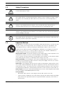
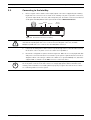
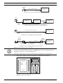
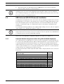
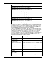
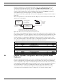
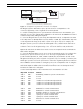
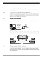
IntuiKey Keyboard Keyboard Version 1.92 en Installation Manual IntuiKey Keyboard Table of Contents | en iii Table of Contents 1 Safety 1 1.1 Important Safety Instructions 1 1.2 Safety Precautions 3 1.3 Important Notices 3 1.4 Customer Support and Service 8 2 Introduction to the IntuiKey Keyboard Series 9 2.1 Unpacking 9 2.2 Understanding the IntuiKey 9 3 Installing the IntuiKey Keyboard 11 3.1 Mounting the IntuiKey 12 3.2 Connecting to the IntuiKey 13 3.3 KBD-Universal (RS-232 Protocol) Installation 15 3.3.1 Keyboard Number Assignments when Using RS-232 Model Keyboards 15 3.3.2 Allegiant System Command Scripts for RS-232 Model Keyboards 16 3.4 Console Expander Configuration when Using RS-232 Model Keyboards 18 3.4.1 Login Feature when Using RS-232 Model Keyboards 20 3.5 IntuiKey Terminal Mode 20 3.6 Configuring the IntuiKey Keyboard 20 3.6.1 Accessing the Keyboard Control Menu 21 3.6.2 Keyboard Control Menu Options 21 4 Troubleshooting 23 4.1 System 23 4.2 Keyboard 23 4.3 Camera Control 24 4.4 Miscellaneous 24 A Security Information 25 Bosch Security Systems, Inc. Installation Manual F.01U.115.018 | 1.92 | 2008.12 iv en | Table of Contents F.01U.115.018 | 1.92 | 2008.12 IntuiKey Keyboard Installation Manual Bosch Security Systems, Inc. IntuiKey Keyboard Safety | en 1 Safety 1.1 Important Safety Instructions 1 Read, follow, and retain for future reference all of the following safety instructions. Heed all warnings on the unit and in the operating instructions before operating the unit. 1. Cleaning - Unplug the unit from the outlet before cleaning. Follow any instructions provided with the unit. Generally, using a dry cloth for cleaning is sufficient, but a moist fluff-free cloth or leather shammy may also be used. Do not use liquid cleaners or aerosol cleaners. 2. Heat Sources - Do not install the unit near any heat sources such as radiators, heaters, stoves, or other equipment (including amplifiers) that produce heat. 3. Ventilation - Any openings in the unit enclosure are provided for ventilation to prevent overheating and ensure reliable operation. Do not block or cover these openings. Do not place the unit in an enclosure unless proper ventilation is provided, or the manufacturer's instructions have been adhered to. 4. Water - Do not use this unit near water, for example near a bathtub, washbowl, sink, laundry basket, in a damp or wet basement, near a swimming pool, in an outdoor installation, or in any area classified as a wet location. To reduce the risk of fire or electrical shock, do not expose this unit to rain or moisture. 5. Object and liquid entry - Never push objects of any kind into this unit through openings as they may touch dangerous voltage points or short-out parts that could result in a fire or electrical shock. Never spill liquid of any kind on the unit. Do not place objects filled with liquids, such as vases or cups, on the unit. 6. Lightning - For added protection during a lightning storm, or when leaving this unit unattended and unused for long periods, unplug the unit from the wall outlet and disconnect the cable system. This will prevent damage to the unit from lightning and power line surges. 7. Controls adjustment - Adjust only those controls specified in the operating instructions. Improper adjustment of other controls may cause damage to the unit. Use of controls or adjustments, or performance of procedures other than those specified, may result in hazardous radiation exposure. 8. Overloading - Do not overload outlets and extension cords. This can cause fire or electrical shock. 9. Power cord and plug protection - Protect the plug and power cord from foot traffic, being pinched by items placed upon or against them at electrical outlets, and its exit from the unit. For units intended to operate with 230 VAC, 50 Hz, the input and output power cord must comply with the latest versions of IEC Publication 227 or IEC Publication 245. 10. Power disconnect - Units with or without ON/OFF switches have power supplied to the unit whenever the power cord is inserted into the power source; however, the unit is operational only when the ON/OFF switch is in the ON position. The power cord is the main power disconnect device for switching off the voltage for all units. Bosch Security Systems, Inc. Installation Manual F.01U.115.018 | 1.92 | 2008.12 2 en | Safety IntuiKey Keyboard 11. Power sources - Operate the unit only from the type of power source indicated on the label. Before proceeding, be sure to disconnect the power from the cable to be installed into the unit. – For battery powered units, refer to the operating instructions. – For external power supplied units, use only the recommended or approved power – For limited power source units, this power source must comply with EN60950. – For 24 VAC units, voltage applied to the unit's power input should not exceed ±10%, supplies. Substitutions may damage the unit or cause fire or shock. or 28 VAC. User-supplied wiring must comply with local electrical codes (Class 2 power levels). Do not ground the supply at the terminals or at the unit's power supply terminals. – If unsure of the type of power supply to use, contact your dealer or local power company. 12. Servicing - Do not attempt to service this unit yourself. Opening or removing covers may expose you to dangerous voltage or other hazards. Refer all servicing to qualified service personnel. 13. Damage requiring service - Unplug the unit from the main AC power source and refer servicing to qualified service personnel when any damage to the equipment has occurred, such as: – the power supply cord or plug is damaged; – exposure to moisture, water, and/or inclement weather (rain, snow, etc.); – liquid has been spilled in or on the equipment; – an object has fallen into the unit; – unit has been dropped or the unit cabinet is damaged; – unit exhibits a distinct change in performance; – unit does not operate normally when the user correctly follows the operating instructions. 14. Replacement parts - Be sure the service technician uses replacement parts specified by the manufacturer, or that have the same characteristics as the original parts. Unauthorized substitutions may cause fire, electrical shock, or other hazards. 15. Safety check - Safety checks should be performed upon completion of service or repairs to the unit to ensure proper operating condition. 16. Installation - Install in accordance with the manufacturer's instructions and in accordance with applicable local codes. 17. Attachments, changes or modifications - Only use attachments/accessories specified by the manufacturer. Any change or modification of the equipment, not expressly approved by Bosch, could void the warranty or, in the case of an authorization agreement, authority to operate the equipment. F.01U.115.018 | 1.92 | 2008.12 Installation Manual Bosch Security Systems, Inc. IntuiKey Keyboard 1.2 Safety | en 3 Safety Precautions DANGER! Indicates a potentially hazardous situation. If not avoided, this could result in serious bodily injury or death. WARNING! High risk: ! ! This symbol indicates an imminently hazardous situation such as “Dangerous Voltage” inside the product. If not avoided, this will result in an electrical shock, serious bodily injury, or death. CAUTION! Medium risk: Indicates a potentially hazardous situation. If not avoided, this may result in minor or moderate injury. Alerts the user to important instructions accompanying the unit. CAUTION! Low risk: (without safety alert symbol) Indicates a potentially hazardous situation. If not avoided, this may result in property damage or risk of damage to the unit. i 1.3 NOTICE! This symbol indicates information or a company policy that relates directly or indirectly to the safety of personnel or protection of property. Important Notices Accessories - Do not place this unit on an unstable stand, tripod, bracket, or mount. The unit may fall, causing serious injury and/or serious damage to the unit. Use only with the cart, stand, tripod, bracket, or table specified by the manufacturer. When a cart is used, use caution and care when moving the cart/apparatus combination to avoid injury from tip-over. Quick stops, excessive force, or uneven surfaces may cause the cart/unit combination to overturn. Mount the unit per the manufacturer's instructions. All-pole power switch - Incorporate an all-pole power switch, with a contact separation of at least 3 mm in each pole, into the electrical installation of the building. If it is needed to open the housing for servicing and/or other activities, use this all-pole switch as the main disconnect device for switching off the voltage to the unit. Camera grounding - For mounting the camera in potentially damp environments, ensure to ground the system using the ground connection of the power supply connector (see section: Connecting external power supply). Camera lens - An assembled camera lens in the outdoor housing must comply and be tested in accordance with UL/IEC60950. Any output or signal lines from the camera must be SELV or Limited Power Source. For safety reasons the environmental specification of the camera lens assembly must be within the environmental specification of -10 °C (14 °F) to 50 °C (122 °F). Camera signal - Protect the cable with a primary protector if the camera signal is beyond 140 feet, in accordance with NEC800 (CEC Section 60). Coax grounding: – Ground the cable system if connecting an outside cable system to the unit. – Connect outdoor equipment to the unit's inputs only after this unit has had its grounding plug connected to a grounded outlet or its ground terminal is properly connected to a ground source. Bosch Security Systems, Inc. Installation Manual F.01U.115.018 | 1.92 | 2008.12 4 en | Safety IntuiKey Keyboard – Disconnect the unit's input connectors from outdoor equipment before disconnecting the grounding plug or grounding terminal. – Follow proper safety precautions such as grounding for any outdoor device connected to this unit. U.S.A. models only - Section 810 of the National Electrical Code, ANSI/NFPA No.70, provides information regarding proper grounding of the mount and supporting structure, grounding of the coax to a discharge unit, size of grounding conductors, location of discharge unit, connection to grounding electrodes, and requirements for the grounding electrode. i NOTICE! This device is intended for use in public areas only. U.S. federal law strictly prohibits surreptitious recording of oral communications. Your Bosch product was developed and manufactured with high-quality material and components that can be recycled and reused. This symbol means that electronic and electrical appliances, which have reached the end of their working life, must be collected and disposed of separately from household waste material. Separate collecting systems are usually in place for disused electronic and electrical products. Please dispose of these units at an environmentally compatible recycling facility, per European Directive 2002/96/EC. Environmental statement - Bosch has a strong commitment towards the environment. This unit has been designed to respect the environment as much as possible. Electrostatic-sensitive device - Use proper CMOS/MOS-FET handling precautions to avoid electrostatic discharge. NOTE: Wear required grounded wrist straps and observe proper ESD safety precautions when handling the electrostatic-sensitive printed circuit boards. Fuse rating - For security protection of the device, the branch circuit protection must be secured with a maximum fuse rating of 16A. This must be in accordance with NEC800 (CEC Section 60). Grounding and polarization - This unit may be equipped with a polarized alternating current line plug (a plug with one blade wider than the other blade). This safety feature allows the plug to fit into the power outlet in only one way. If unable to insert the plug fully into the outlet, contact a locally certified electrician to replace the obsolete outlet. Do not defeat the safety purpose of the polarized plug. Alternately, this unit may be equipped with a 3-pole grounding plug (a plug with a third pin for earth grounding). This safety feature allows the plug to fit into a grounded power outlet only. If unable to insert the plug into the outlet, contact a locally certified electrician to replace the obsolete outlet. Do not defeat the safety purpose of the grounding plug. Moving - Disconnect the power before moving the unit. Move the unit with care. Excessive force or shock may damage the unit and the hard disk drives. Outdoor signals - The installation for outdoor signals, especially regarding clearance from power and lightning conductors and transient protection, must be in accordance with NEC725 and NEC800 (CEC Rule 16-224 and CEC Section 60). Permanently connected equipment - Incorporate a readily accessible disconnect device in the building installation wiring. Pluggable equipment - Install the socket outlet near the equipment so it is easily accessible. PoE - Never supply power via the Ethernet connection (PoE) when power is already supplied via the power connector. Power disconnect - Units have power supplied whenever the power cord is inserted into the power source. The power cord is the main power disconnect for all units. F.01U.115.018 | 1.92 | 2008.12 Installation Manual Bosch Security Systems, Inc. IntuiKey Keyboard Safety | en 5 Power lines - Do not locate the camera near overhead power lines, power circuits, or electrical lights, nor where it may contact such power lines, circuits, or lights. SELV All the input/output ports are Safety Extra Low Voltage (SELV) circuits. SELV circuits should only be connected to other SELV circuits. Because the ISDN circuits are treated like telephone-network voltage, avoid connecting the SELV circuit to the Telephone Network Voltage (TNV) circuits. Video loss - Video loss is inherent to digital video recording; therefore, Bosch Security Systems cannot be held liable for any damage that results from missing video information. To minimize the risk of lost digital information, Bosch Security Systems recommends multiple, redundant recording systems, and a procedure to back up all analog and digital information. i NOTICE! This is a class A product. In a domestic environment this product may cause radio interference, in which case the user may be required to take adequate measures. FCC & ICES INFORMATION (U.S.A. and Canadian Models Only) This device complies with part 15 of the FCC Rules. Operation is subject to the following conditions: – this device may not cause harmful interference, and – this device must accept any interference received, including interference that may cause undesired operation. Note This equipment has been tested and found to comply with the limits for a Class A digital device, pursuant to Part 15 of the FCC Rules and ICES-003 of Industry Canada. These limits are designed to provide reasonable protection against harmful interference when the equipment is operated in a commercial environment. This equipment generates, uses, and radiates radio frequency energy and, if not installed and used in accordance with the instruction manual, may cause harmful interference to radio communications. Operation of this equipment in a residential area is likely to cause harmful interference, in which case the user will be required to correct the interference at his expense. Intentional or unintentional modifications, not expressly approved by the party responsible for compliance, shall not be made. Any such modifications could void the user's authority to operate the equipment. If necessary, the user should consult the dealer or an experienced radio/television technician for corrective action. The user may find the following booklet, prepared by the Federal Communications Commission, helpful: How to Identify and Resolve Radio-TV Interference Problems. This booklet is available from the U.S. Government Printing Office, Washington, DC 20402, Stock No. 004-000-00345-4. Bosch Security Systems, Inc. Installation Manual F.01U.115.018 | 1.92 | 2008.12 6 en | Safety IntuiKey Keyboard INFORMATIONS FCC ET ICES (commercial applications) (modèles utilisés aux États-Unis et au Canada uniquement) Ce produit est conforme aux normes FCC partie 15. la mise en service est soumises aux deux conditions suivantes: – – cet appareil ne peut pas provoquer d'interférence nuisible et cet appareil doit pouvoir tolérer toutes les interférences auxquelles il est soumit, y compris les interférences qui pourraient influer sur son bon fonctionnement. AVERTISSEMENT: Suite à différents tests, cet appareil s’est révélé conforme aux exigences imposées aux appareils numériques de Classe A en vertu de la section 15 du règlement de la Commission fédérale des communications des États-Unis (FCC). Ces contraintes sont destinées à fournir une protection raisonnable contre les interférences nuisibles quand l'appareil est utilisé dans une installation commerciale. Cette appareil génère, utilise et émet de l'energie de fréquence radio, et peut, en cas d'installation ou d'utilisation non conforme aux instructions, générer des interférences nuisibles aux communications radio. L’utilisation de ce produit dans une zone résidentielle peut provoquer des interférences nuisibles. Le cas échéant, l’utilisateur devra remédier à ces interférences à ses propres frais. Au besoin, l’utilisateur consultera son revendeur ou un technicien qualifié en radio/télévision, qui procédera à une opération corrective. La brochure suivante, publiée par la Commission fédérale des communications (FCC), peut s’avérer utile : « How to Identify and Resolve RadioTV Interference Problems » (Comment identifier et résoudre les problèmes d’interférences de radio et de télévision). Cette brochure est disponible auprès du U.S. Government Printing Office, Washington, DC 20402, États-Unis, sous la référence n° 004-000-00345-4. AVERTISSEMENT: Ce produit est un appareil de Classe A. Son utilisation dans une zone résidentielle risque de provoquer des interférences. Le cas échéant, l’utilisateur devra prendre les mesures nécessaires pour y remédier. F.01U.115.018 | 1.92 | 2008.12 Installation Manual Bosch Security Systems, Inc. IntuiKey Keyboard Safety | en 7 Disclaimer Underwriter Laboratories Inc. (“UL”) has not tested the performance or reliability of the security or signaling aspects of this product. UL has only tested fire, shock and/or casualty hazards as outlined in UL's Standard(s) for Safety for Closed Circuit Television Equipment, UL 2044. UL Certification does not cover the performance or reliability of the security or signaling aspects of this product. UL MAKES NO REPRESENTATIONS, WARRANTIES, OR CERTIFICATIONS WHATSOEVER REGARDING THE PERFORMANCE OR RELIABILITY OF ANY SECURITY OR SIGNALING RELATED FUNCTIONS OF THIS PRODUCT. Disclaimer Underwriter Laboratories Inc. (“UL”) has not tested the performance or reliability of the security or signaling aspects of this product. UL has only tested fire, shock and/or casualty hazards as outlined in UL's Standard(s) for Safety for Information Technology Equipment, UL 60950-1. UL Certification does not cover the performance or reliability of the security or signaling aspects of this product. UL MAKES NO REPRESENTATIONS, WARRANTIES, OR CERTIFICATIONS WHATSOEVER REGARDING THE PERFORMANCE OR RELIABILITY OF ANY SECURITY OR SIGNALINGRELATED FUNCTIONS OF THIS PRODUCT. Copyright This user guide is the intellectual property of Bosch Security Systems, Inc. and is protected by copyright. All rights reserved. Trademarks All hardware and software product names used in this document are likely to be registered trademarks and must be treated accordingly. NOTICE! This user guide has been compiled with great care and the information it contains has been i thoroughly verified. The text was complete and correct at the time of printing. The ongoing development of the products may mean that the content of the user guide can change without notice. Bosch Security Systems accepts no liability for damage resulting directly or indirectly from faults, incompleteness or discrepancies between the user guide and the product described. Bosch Security Systems, Inc. Installation Manual F.01U.115.018 | 1.92 | 2008.12 8 1.4 en | Safety IntuiKey Keyboard Customer Support and Service If this unit needs service, contact the nearest Bosch Security Systems Service Center for authorization to return and shipping instructions. Service Centers USA Telephone: 800-366-2283 or 585-340-4162 Fax: 800-366-1329 Email: [email protected] Customer Service Telephone: 888-289-0096 Fax: 585-223-9180 Email: [email protected] Technical Support Telephone: 800-289-0096 or 800-326-1450 Fax: 585-223-3508 or 717-735-6560 Email: [email protected] Repair Center Telephone: 585-421-4220 Fax: 585-223-9180 or 717-735-6561 Email: [email protected] Canada Telephone: 514-738-2434 Fax: 514-738-8480 Europe, Middle East & Asia Pacific Region Telephone: +31 (0) 76 5721 500 Fax: +31 (0) 76 5721 413 Email: RMADesk@[email protected] More information For additional information, please contact your Bosch Security Systems representative or visit our web site at www.boschsecurity.com F.01U.115.018 | 1.92 | 2008.12 Installation Manual Bosch Security Systems, Inc. IntuiKey Keyboard 2 Introduction to the IntuiKey Keyboard Series | en 9 Introduction to the IntuiKey Keyboard Series This manual contains all the information necessary to safely install the IntuiKey Keyboard. Consult the Table of Contents for a detailed list of topics covered. Step-by-step procedures, and illustrations guide you through each phase of IntuiKey setup. Installation of the IntuiKey includes mounting and connecting the unit to other system components. The plug and play design makes installation and setup of the unit quick and easy. 2.1 Unpacking Unpack carefully. This electronic equipment should be handled with care to prevent damage to the unit. Check for the following items: – IntuiKey Keyboard with Integral Joystick – Installation Manual (this manual) IntuiKey document CD – Two (2) 3 m (10 ft) power cable(s) – 290 Ohm Terminator (p/n F01U067451) If any items appear to have been damaged in shipment, replace the item(s) properly in the shipping carton and notify the shipping company. If any items are missing, notify your Bosch Security Systems Sales Representative or Customer Service Representative. i 2.2 NOTICE! The shipping carton is the safest container in which to transport the unit. Save it and all packing materials for future use. Understanding the IntuiKey The IntuiKey provides easy, full-function system control and programming of a variety of Bosch security products including Allegiant Switchers, Divar Series digital video recorders, System4® Multiplexers, and VCRs. System cameras can be controlled through any of these devices linked to the keyboard. Backwards compatibility with existing Bosch products enables the IntuiKey’s integration into almost any system configuration (no additional devices/interfaces necessary). The IntuiKey user interface simplifies system programming by providing intuitive menus, allowing easy and flexible system control navigation. Using the optional KBD-SFTCFG software package (sold separately), customized menu screens can be programmed to activate Allegiant Command Script macro functions. In addition, this PC-based software supports individualized labeling of the softkey text displays. The IntuiKey is available in two models, each with an integral, variable speed pan/tilt/zoom joystick. The KBD-Universal provides control of any combination of system components, including Allegiant Switchers, Divar Series DVRs, and System4 Multiplexers. The KBD-Digital provides control of Divar Series DVRs and System4 Multiplexers. Both types can be used with Bosch VMS or VIDOS Video Management Software. The IntuiKey also supports the ability to operate in a Terminal mode. In Terminal mode, the operation of the keyboard is completely controlled by third-party software via an RS-232 interface. Optional equipment available from Bosch for use with the IntuiKey Keyboards includes an external power supply, rack mount kit, and keyboard extenders. Bosch Security Systems, Inc. Installation Manual F.01U.115.018 | 1.92 | 2008.12 10 en | Introduction to the IntuiKey Keyboard Series IntuiKey Keyboard The following chart provides basic operating specifications: Electrical (operating) Mechanical (construction) Voltage: Finish: Charcoal 12–15 VDC (supplied by any one or a combination of Allegiant Switcher, Divar Series digital video recorder, System4 Multiplexer, and an optional listed Class 2 or equivalent power supply Power: 5 Watts nominal Width: 12.00 in. (327.66 mm) Signal: – Allegiant 2 wire RS-485, 9600 Baud, 8 bits, No parity, 1 Depth: 7.518 in. (190.95 mm) Stop bit Height: 2.969 in. (75.41 mm) Weight: 2.62 lb (1.19 kg) – MUX/DVR; 2 wire RS-485, 19,200 Baud, 8 bits, No parity, 1 Stop bit – RS-232 Serial Port, RS-232 RTS/CTS Handshaking, 9600/19,200 Baud, 8 bits, No parity, 1 Stop bit Compatibility: Connectors: Backwards compatible with all Allegiant systems utilizing – released 6/94). Compatible with all Divar Series of digital – MUX/DVR RJ-11 Data/ Power video recorders. Backwards compatible with all System4 – Multiplexers. Allegiant RJ-11 Data/ Power variable speed protocol (CPU Firmware 5.3 and higher, Aux Power (optional) 12 VDC Bayonet Plug – RS-232 Serial Port; Male Null Modem 9-pin D-sub. F.01U.115.018 | 1.92 | 2008.12 Installation Manual Bosch Security Systems, Inc. IntuiKey Keyboard 3 Installing the IntuiKey Keyboard | en 11 Installing the IntuiKey Keyboard The IntuiKey is compatible with many controller devices. In certain configurations a single keyboard is connected to a single controller device. In other configurations a keyboard can control up to thirty (30) multiplexers/Divar Series (1, 2, XF) DVRs, and one (1) video switcher simultaneously. See the table below for supported Divar features. Hardware Features Divar Divar Easy Divar MR Divar XF Control of multiple DVRs using single keyboard Y N N Y LTC 2604 Keyboard Port Expander Support Y N N N Table 3.1 Supported Divar features by models If more than one IntuiKey is to be connected to a single multiplexer or group of daisy-chained multiplexers, a keyboard port expander must be added. The Allegiant Series of video switchers have a varying number of keyboard ports depending on model number. If more than eight keyboards are required on one of the larger Allegiant Series Switchers, an Allegiant keyboard expander must be added. Bosch offers the following Keyboard Expanders: – For use with Allegiant Series Switchers: – – LTC 8714 Keyboard Port Expander, and LTC 8715 Keyboard Expander For use with Divar Series DVRs (1 & 2) or System4 Video Multiplexers: – LTC 2604 Keyboard Port Expander Please contact your Bosch Security Systems Sales Representative for more information. KBD-Digital PHILIPS Prod Mon Shot Clr 1 2 3 4 5 6 7 8 9 0 RS-485 Divar Digital Video Recorder One IntuiKey to One Device Figure 3.1 Typical Configuration for all Divars Bosch Security Systems, Inc. Installation Manual F.01U.115.018 | 1.92 | 2008.12 12 en | Installing the IntuiKey Keyboard IntuiKey Keyboard KBD-Universal Divar Digital Video Recorder #1 PHILIPS Prod Mon Shot Clr 1 2 3 4 5 6 7 8 9 0 RS-485 Divar Digital Video Recorder #2 Divar Digital Video Recorder # 30 Allegiant Series Video Switcher RS-485 One IntuiKey to Multiple Divars (Series 1 &2) KBD-Digital PHILIPS Prod Mon Shot Clr KBD-Universal 1 2 3 4 5 6 7 8 9 0 PHILIPS Prod Mon Shot Clr 1 2 3 4 5 6 7 8 9 RS-485 PHILIPS ALLPLEX VCR APX B REC SEQ REC PLAY B SEQ System4 Multiplexer System4 Multiplexer LTC 2604 Keyboard Expander 0 # PLAY SET 1 SHOT 4 AUX+ 7 AUX- 2 3 5 6 8 9 0/10 11 12 13 14 15 ACT 16 ALLPLEX ALM ( ) VCR ® Multiple Keyboard Models to Multiple System4 Multiplexers LTC 2601/00 PHILIPS Prod Mon Shot Clr KBD-Universal 1 2 3 4 5 6 7 8 9 KBD-Digital 0 PHILIPS Prod Mon Shot Clr 1 2 3 4 5 6 7 8 9 LTC 2604 Keyboard Expander 0 RS-485 Divar Digital Video Recorder (Series 1 &2) Divar Digital Video Recorder (Series 1 &2) PHILIPS Prod Mon Shot Clr 1 2 3 4 5 6 7 8 9 0 KBD-Digital RS-485 PHILIPS Prod Optional LTC 8714 Expander Optional LTC 8715 Expander Allegiant Series Video Switcher PHILIPS Mon Prod Mon Shot Clr Shot Clr 1 2 3 4 5 6 7 8 9 0 KBD-Universal 1 2 3 4 5 6 7 8 9 0 KBD-Universal Multiple Keyboards to Multiple Devices Figure 3.2 Supported Configurations for Divar (Series 1 &2), System4 Multiplexers, and Switchers System power connections must also be considered. Depending on the distance between the keyboard and devices under control, an external power supply (listed Class 2 or equivalent) may be needed according to the following specifications: Distance from Keyboard to Device under Control1 Less than 10 ft (3.5 m) Between 10 ft (3.5 m) and 100 ft (30 m) Greater than 100 ft (30 m) Optional Equipement Needed None External Power Supply LTC 8557/60(50) Keyboard Extender 1. Distances may vary depending on the number of keyboards connected. 3.1 Mounting the IntuiKey The IntuiKey LCD displays are readable in all but direct sunlight conditions. Locate the keyboard on a flat, horizontal surface, with an optimal LCD viewing angle of 0 to 20 degrees from vertical. Display contrast levels are software-controlled and may be adjusted via the Keyboard Control menu. An optional rack mount kit may also be used. F.01U.115.018 | 1.92 | 2008.12 Installation Manual Bosch Security Systems, Inc. IntuiKey Keyboard 3.2 Installing the IntuiKey Keyboard | en 13 Connecting to the IntuiKey 1. Refer to Figure 3.8 for details on the input/output connections supplied by the IntuiKey Keyboard. Four connectors are located on the IntuiKey rear panel: (2) RJ-11 connectors, (1) female 9-pin sub-D connector, and a DC power jack. The RJ-11 connectors are labeled as Allegiant and MUX/DVR and the 9-pin sub-D is labeled RS-232 Serial Port. Allegiant DC Power MUX/DVR MUX / DVR ALLEGIANT 12 VDC RS-232 Serial Port RS-232 SERIAL PORT Cable Strain Reliefs Figure 3.3 Back Panel Connections of IntuiKey ! CAUTION! To ensure proper system functioning and to prevent damage to the unit, it is critical that only Allegiant devices be connected to the Allegiant connector, and that Multiplexer/DVR devices be connected to the MUX/DVR connector. 2. If desired, the data/power cables can be looped through either of the two tabs found at the bottom of the rear panel to increase strain relief capabilities. 3. Review the configuration options shown in Figure 3.9. Make the necessary keyboard data and power connections that are best suited to your system requirements based on these diagrams. When connecting to a Divar Series DVR or to a System4 Multiplexer, attach the supplied 390 ? terminator to the Out connector on the last device. NOTICE! In systems having multiple Divar Series DVRs or multiple System4 Multiplexers, use i the front panel controls on the video devices to assign appropriate address numbers and starting camera numbers. The IntuiKey will not properly recognize the video devices if there are conflicting addresses in the system. Bosch Security Systems, Inc. Installation Manual F.01U.115.018 | 1.92 | 2008.12 14 en | Installing the IntuiKey Keyboard IntuiKey Keyboard IntuiKey Keyboard 3 m (10 ft) Data/Power Cable PHILIPS Prod Video Device Mon Shot Clr 1 2 3 4 5 6 7 8 9 0 (See Note) IntuiKey Connection Using Supplied Data Cable IntuiKey Keyboard PHILIPS Prod Mon Shot Clr 1 2 3 4 5 6 7 8 9 Video Device 0 Video Device IN OUT Supplied 3 m (10 ft) Data/Power Cable Video Device IN OUT IN OUT RS-485 (See Note) Multiple Divar Digital Video Recorders or System4 Multiplexers IntuiKey Keyboard 30 m (100 ft) LTC 8558/00 Data Cable Video Device PHILIPS Prod Mon Shot Clr 1 2 3 4 5 6 7 8 9 0 (See Note) Optional Power Supply IntuiKey Connection Using Optional LTC 8558 Data Cable PHILIPS Prod Mon Supplied 3 m (10 ft) Data/Power Cable Supplied 3 m (10 ft) Data Cable RS-485 Video Device Shot Clr 1 2 3 4 5 6 7 8 9 0 IntuiKey Keyboard User Supplied Shielded Twisted Pair Cable Up to 1.5 km (5000 ft) LTC 8557 Junction Box LTC 8557 Junction Box (See Note) IntuiKey Connection Using Optional LTC 8557 Remote Hookup Kit Figure 3.4 Typical IntuiKey Connection Options NOTICE! i 1) Attach the supplied 390 W terminator to the Out connector when using a Divar Series Digital Video Recorder or a System4 Multiplexer. 2) At time of initial release of the Divar XF, keyboard loopthrough is not supported. 4. After power is applied, the keyboard initializes and displays the following: KBD – Universal KBD – Universal Bosch Security System Copyright 2005 Protocol: Firmware Ver: Bootldr Ver: Hardware Ver: Bosch Security System Firmware Ver: x:xx .6P x:xx x:xx x:xx Prod Mon Clr Press [CLR] key to Exit Shot 1 2 3 4 5 6 7 8 9 0 Figure 3.5 Initial Power-up Display F.01U.115.018 | 1.92 | 2008.12 Installation Manual Bosch Security Systems, Inc. IntuiKey Keyboard Installing the IntuiKey Keyboard | en 5. 15 After a brief pause (or immediately after the CLR button is pressed) the keyboard performs a brief search for connected devices. NOTICE! On initial power-up, factory reset, or firmware upgrade the IntuiKey displays the i 3.3 Language menu. Select the desired language by pressing the softkey next to the language title. If additional languages are available, the arrow softkeys at the bottom of the screen can be used to scroll to a second menu screen. KBD-Universal (RS-232 Protocol) Installation The KBD-Universal keyboard can be connected to either an Allegiant LTC 8712 Series Console Port Expander accessory unit, or the 9-pin Console or Printer (if equipped) RS-232 port on the back of the Allegiant system. The keyboard may be connected via hardwired cable, dial-up modem, or using another type of communication system conforming to standard RS-232 transmission. For each keyboard being installed, a user-supplied 9-pin mating connector, and user-supplied cable suitable for use with RS-232 signals is required. i NOTICE! To configure the IntuiKey to operate using Allegiant RS-232 protocol, enter the Keyboard Control menu and press the protocol button. Enter the password (see APPENDIX A) to change the protocol mode from RS-485 to RS-232. Refer to the most applicable configuration diagram. See Figure 3.6 or Figure 3.7. 3.3.1 Keyboard Number Assignments when Using RS-232 Model Keyboards Use of RS-232 protocol keyboards does not increase the total number of keyboards that can be connected to an Allegiant switcher. When an RS-232 keyboard is connected in the system, a standard keyboard port will automatically become disabled. The disabled keyboard port number will be based on the interface connection type of the RS-232 keyboard. Keeping track of these keyboard numbers is necessary when priority-based restrictions, or other keyboard related lockouts, are assigned and used in the system. The table below indicates which keyboard number will be assigned, based on the connection being used. Keyboard Keyboard Connection Type Direct to Console port Direct to Printer port Port 1 of Expander, when Expander Port 2 of Expander, when Expander Port 3 of Expander, when Expander Port 4 of Expander, when Expander Port 1 of Expander, when Expander Port 2 of Expander, when Expander Port 3 of Expander, when Expander Port 4 of Expander, when Expander Bosch Security Systems, Inc. is connected to Console port is connected to Console port is connected to Console port is connected to Console port is connected to Printer port is connected to Printer port is connected to Printer port is connected to Printer port Installation Manual Number 1 5 1 2 3 4 5 6 7 8 F.01U.115.018 | 1.92 | 2008.12 16 en | Installing the IntuiKey Keyboard 3.3.2 IntuiKey Keyboard Allegiant System Command Scripts for RS-232 Model Keyboards When a keyboard is being connected to an Allegiant’s Console port, or an Allegiant Printer port configured to operate in the Console mode, the Allegiant must be preprogrammed so the port will operate in the RS-232 keyboard mode. The mode of the Allegiant’s Console port can be changed either by a manually entered ASCII text command, or preprogramming the Allegiant CPU with an Allegiant Command Script. The Command Script method is preferred since the appropriate settings are automatically restored after a system power loss or reset. Manually entered commands remain valid only until the system is reset or powered off/on, so typically they should be used only for temporary or test purposes. To manually configure an Allegiant’s Console port to operate in the keyboard mode, it is necessary to connect to the system via Windows® HyperTerminal or another dumb terminal emulator. i NOTICE! Allegiant Console and Printer RS-232 ports do not use a standard RS-232 pinout. Use of an Allegiant Console cable LTC 8506/00 is recommended as seen in the pinout diagram below. 9-pin Male Allegiant 9-pin Female (Console) 1 2 3 4 5 6 7 8 9 (PC) None 3 2 1 8 None 5 None None Pins 4 and 6 are jumped Pins 1 and 7 are jumped Designation Chassis GND RX TX CTS RTS No Connection Data GND No Connection No Connection The Allegiant RS-232 settings are user-programmable, but the default settings are: – Baud: 19,200 – Stop bits: 1 – Data bits: 8 – Parity: None – Handshake: None Once online with the system, an Allegiant prompt appears each time Enter is pressed. The prompt looks as follows: TC8x00 > where x is a digit from one to nine (depending on the Allegiant model). At the system prompt, manually enter the appropriate command, based on the Allegiant port in use, and type of keyboard interface. Refer to the table below to determine the correct command. Enter the command exactly as shown below, then press ENTER. F.01U.115.018 | 1.92 | 2008.12 Installation Manual Bosch Security Systems, Inc. IntuiKey Keyboard Installing the IntuiKey Keyboard | en 17 Keyboard interface connection type Direct to Console port (except LTC 8900) Command: SET-PORT-RS232 0 4 8 0 1 0;_SET_KBD_MODE 01 Direct to Printer port (except LTC 8900) Command: SET-PORT-RS232 4 4 8 0 1 0;_SET_KBD_MODE 4 1 Modem connected to Console port (except LTC 8900) Command: SET-PORT-RS232 0 4 8 0 1 1;_SET_KBD_MODE 0 1 Modem connected to Printer port (except LTC 8900) Command: SET-PORT-RS232 4 4 8 0 1 1;_SET_KBD_MODE 4 1 Direct to Controller port (LTC 8900 only) Command: SET-PORT-RS232 0 4 8 0 1 0;_SET_KBD__MODE 0 1 Direct to Console port (LTC 8900 only) Command: SET-PORT-RS232 4 4 8 0 1 0;_SET_KBD_MODE 4 1 Modem connected to Controller port (LTC 8900 only) Command: SET-PORT-RS232 0 4 8 0 1 1;_SET_KBD_MODE 0 1 Modem connected to Console port (LTC 8900 only) Command: SET-PORT-RS232 4 4 8 0 1 1;_SET_KBD_MODE 4 1 After entering the command, the port will immediately begin to operate in the keyboard mode. The port will generate a series of constantly repeating codes. The setting remains in effect until the system is reset, powered off/on, or manually cancelled by entering Ctrl-C several times, using Windows HyperTerminal program operating at 9600 baud. If using the LTC 8059 Master Control Software, while online, select the Command Script tab and enter the script for your connection type exactly as it appears in the next table: After the script has been entered, download the script into the Allegiant CPU. Reset the system by powering the CPU off/on, or by entering Keyboard User Function 15 on an operating keyboard. The specified port will begin to operate in the keyboard mode. The port will remain in the keyboard mode unless manually cancelled by entering Ctrl-C several times using Windows HyperTerminal program, operating at 9600 baud. Keyboard interface connection Command Script type Direct to Console port Begin @boot SET-PORT-RS232 0 4 8 0 1 0_SET_KBD_MODE 01 break (except LTC 8900) Direct to Printer port Begin @boot SET-PORT-RS232 4 4 8 0 1 0 _SET_KBD_MODE 4 1 break (except LTC 8900) Modem connected to Console Begin @boot SET-PORT-RS232 0 4 8 0 1 1 _SET_KBD_MODE 0 1 break port (except LTC 8900) Modem connected to Printer Begin @boot SET-PORT-RS232 4 4 8 0 1 1 _SET_KBD_MODE 4 1 break port (except LTC 8900) Direct to Controller port Begin @boot SET-PORT-RS232 0 4 8 0 1 0 _SET_KBD_MODE 0 1 break (LTC 8900) Direct to Console port Begin @boot SET-PORT-RS232 4 4 8 0 1 0 _SET_KBD_MODE 4 1 break (LTC 8900) Modem connected to Controller Begin @boot SET-PORT-RS232 0 4 8 0 1 1 _SET_KBD_MODE 0 1 break port (LTC 8900) Modem connected to Console Begin @boot SET-PORT-RS232 4 4 8 0 1 1 _SET_KBD_MODE 4 1 break port (LTC 8900) Bosch Security Systems, Inc. Installation Manual F.01U.115.018 | 1.92 | 2008.12 18 en | Installing the IntuiKey Keyboard IntuiKey Keyboard After the script has been entered, download the script into the Allegiant CPU. Reset the system by powering the CPU off/on, or by entering Keyboard User Function 15 on an operating keyboard. The specified port begins to operate in the keyboard mode. The port remains in the keyboard mode unless manually cancelled by entering Ctrl-C several times using Windows HyperTerminal program, operating at 9600 baud. The keyboard can now be physically connected to the Allegiant according to details shown in Figure 3.6. Once the keyboard is in communication with the Allegiant, camera and monitor numbers will appear in the LED displays. Allegiant system main CPU bay User-supplied female 9-pin D connector CONSOLE port on Allegiant system must be configured for RS-232 Keyboard mode (refer to text for details) BOSCH Prod Mon Shot Clr 1 2 3 4 5 6 7 8 9 0 3 m (10 ft) data/ power cable supplied with keyboard User-supplied cable or other link suitable for full duplex RS-232 transmissions at 9600 baud Console pin 2 (Rx) to Tx of link or directly to pin 3 of IntuiKey's 9 pin connector Console pin 3 (Tx) to Rx of link or directly to pin 2 of IntuiKey's 9 pin connector Console pin 7 (Gnd) to Data Gnd of link or directly to pin 5 of IntuiKey's 9 pin connector Figure 3.6 Direct Connection to Allegiant’s Console/Printer Port The modem on the Allegiant side must be set to an auto answer mode, and the modem on the keyboard side must be set to an originate mode. The modem must also be programmed to dial the phone number or otherwise initiate the connection to the other modem. In some cases, modem settings are configured via dipswitches found on the back of the modem. In other cases, the modem must be connected to a PC for configuration. The below settings represent the dipswitch configuration required for US Robotics Sportster modems. Allegiant-side Modem Dip Switch Setting 1 DOWN 2 UP 3 DOWN 4 UP 5 DOWN 6 DOWN 7 DOWN 8 DOWN 3.4 Modem Function DTR Override Verbal Result Codes Display Result Codes Echo Offline Commands Suppress Auto Answer Carrier Detect Override Load Factory Defaults Smart Mode Keyboard-side Modem Dip Switch Setting 1 DOWN 2 UP 3 DOWN 4 UP 5 UP 6 UP 7 DOWN 8 DOWN Console Expander Configuration when Using RS-232 Model Keyboards RS-232 model keyboards may be connected to an Allegiant system using the LTC 8712 Series Console Port Expander, as shown in Figure 3.7. An LTC 8712 Series Console Port Expander can be configured to support up to four RS-232 Keyboard connections. Other devices, such as a PC running the Allegiant Master Control software, can be connected to the unused ports of the Port Expander. Because the Port Expander supports only a single baud rate for the external connections, and the RS-232 keyboards require 9600 baud, all external devices connecting to the Port Expander must be configured to for operation at this setting. F.01U.115.018 | 1.92 | 2008.12 Installation Manual Bosch Security Systems, Inc. IntuiKey Keyboard Installing the IntuiKey Keyboard | en Refer to text regarding setup of the Allegiant & LTC 8712 to operate in Allegiant Keyboard mode. Allegiant system main CPU bay BOSCH Prod Mon Shot Clr 1 2 3 4 5 6 7 8 9 0 LTC 8712 Expander 4 3 2 1 User-supplied female 9-pin D connector. 19 3 m (10 ft) data/ power cable supplied with keyboard User-supplied cable or other link suitable for full duplex RS-232 transmissions at 9600 baud Expander pin 2 (Rx) to Tx of link or directly to pin 3 of IntuiKey's 9 pin connector Expander pin 3 (Tx) to Rx of link or directly to pin 2 of IntuiKey's 9 pin connector Expander pin 7 (Gnd) to Data Gnd of link or directly to pin 5 of IntuiKey's 9 pin connector Figure 3.7 Configuration using LTC 8712 Series Console Port Expander On Allegiant systems with a Printer port, up to two Console Port Expanders can be connected, supporting a total of eight RS-232 model keyboards. To configure an Allegiant system to operate with an LTC 8712 Console Port Expander, you must have access to the Allegiant CPU’s dipswitches, the PC-based LTC 8059 Master Control Software, and possibly an Allegiant keyboard. To convert an Allegiant Console port using a CPU dipswitch method, set dipswitches 3 and 4 to the ON position on CPU dipswitch S1, S100, S1001, or S0201 (the switch number depends on the Allegiant model being used). After a system reset (power off/on, for example), the Allegiant’s Console port is forced into the Port Expander mode, and the RS-232 data rate is automatically set to 57,600 baud. To convert an Allegiant Console port via the Master Control Software, connect to the Allegiant and go online. Select the Parameter tab, and then the Options tab. Check the box labeled Set Console Port to Port-Expander mode. Download the table into the Allegiant. To convert an Allegiant Printer port to operate in the Port Expander mode, first configure the Printer port to operate as a Console port. This is done by setting dipswitch 4 to the ON position on CPU dipswitch S2, S101, S1002, or S0202 (the switch number depends on the Allegiant model being used). After a system reset (power off/on, for example), the Printer port will begin to operate as a Console port. Next, use either the Allegiant Keyboard User Function 38 or the Master Control Software to change the port to the Port Expander mode. If using the Master Control Software, connect to the Allegiant and go online. Select the Parameter tab, and then the Options tab. Check the box labeled Set Printer Port to Port-Expander mode. Download the table into the Allegiant. Set the internal dipswitches of the LTC 8712 Console Port Expander as follows: Dip Switch 401.1 401.2 401.3 401.4 401.5 401.6 401.7 401.8 Position ON (down) ON OFF OFF ON ON ON ON Comment 57,600 Baud for system communication Handshaking enabled for system communication Reserved Reserved To enable Port 1 for RS-232 Keyboard mode To enable Port 2 for RS-232 Keyboard mode To enable Port 3 for RS-232 Keyboard mode To enable Port 4 for RS-232 Keyboard mode 402.1 402.2 402.3 402.4 402.5 402.6 402.7 402.8 OFF ON OFF OFF OFF OFF OFF OFF 9600 Baud for external communications 9600 Baud for external communications Handshake disabled for external communications 1 Stop Bit for external communications No parity for external communications No parity for external communications 8 data bits for external communications Reserved Bosch Security Systems, Inc. Installation Manual F.01U.115.018 | 1.92 | 2008.12 20 en | Installing the IntuiKey Keyboard IntuiKey Keyboard Remember to power the Console Port Expander off/on whenever any changes are made to its internal dipswitches. Connect the data cable supplied with the LTC 8712 Console Port Expander between the unit and the appropriately configured port on the Allegiant. For further details refer to the instructions supplied with the LTC 8712 Port Expander unit. The RS-232 keyboard can now be connected to the appropriate port of the Port Expander, as shown in Figure 3.7. 3.4.1 Login Feature when Using RS-232 Model Keyboards The Allegiant’s keyboard login feature is not affected by use of RS-232 keyboards. If desired, this feature can be enabled to provide additional security to the system. Note that it is not possible to use the Allegiant’s Console port login feature. The RS-232 keyboards must have unrestricted access to the Allegiant’s RS-232 ports. 3.5 IntuiKey Terminal Mode When the IntuiKey is operating in Terminal mode, its behavior is completely determined by the third-party software running on a PC. All communication between the keyboard and the thirdparty PC is performed through an RS-232 interface. The following diagram illustrates this configuration: Power PC running 3rd party software designed to communicate with IntuiKey Supply BOSC H Pro d Mo n Sh ot Cl r 3 1 2 4 5 6 7 0 8 9 IntuiKey (Terminal mode) RS-232 Figure 3.8 Terminal Mode This connection requires a standard Null modem RS232 link. If desired, the Bosch Security Systems cable S1385 can be used. Connect one end of the RS-232 interface cable to the 9-pin RS-232 Serial Port located on the far right side of the rear of the keyboard. Connect the other end of the RS-232 interface cable to a COM port on the PC. IntuiKey RS-232 Port Connector 5 4 3 2 1 9 8 7 6 9-pin Female 1 2 3 4 5 6 7 8 9 1 2 3 4 5 6 7 8 9 PC Serial Port Connector 5 4 3 2 1 9 8 7 6 9-pin Female 72.0-inch Figure 3.9 S1385 Cable Pinout 3.6 Configuring the IntuiKey Keyboard The IntuiKey Keyboard plug and play design allows operation to begin as soon as the keyboard is connected to system components. However, if you desire to review the default settings, or wish to change any of these settings, refer to the following information and procedures for the Keyboard Control Mode. F.01U.115.018 | 1.92 | 2008.12 Installation Manual Bosch Security Systems, Inc. IntuiKey Keyboard 3.6.1 Installing the IntuiKey Keyboard | en 21 Accessing the Keyboard Control Menu 1. 2. Press PROD to view the Product Selection menu. Press the softkey labeled Keyboard Control. The Keyboard Control softkey can always be found at the very end of the device listings. 3. The Softkey Display shows the Keyboard Control main menu (see Figure 3.10). A review of the Keyboard Control menu options follows. Exit Firmware Upgrade Factory Reset Protocol RS-485 Keyboard Test Allegiant Baud 9600 Contrast Adjust LCD Test Joystick Auto Cal. Key Click On/Off Display Inverse Normal Language Select Figure 3.10 3.6.2 Keyboard Control Menu Keyboard Control Menu Options Exit Factory Reset Reverts to the Product Selection menu. Resets the keyboard to the following states: – Protocol Product Selected: NONE – Key Click: ON – Display Inverse: Normal (black on white) – MUX Destination: Addr 1 – Softkey Contrast: 9 – Status Display Contrast: 6 – MUX User Level: No Access – Language: NONE – Allegiant Baud: 9600 This password-protected option is used to set the Allegiant communication protocol. Default is RS-485. When using a Terminal Mode connection, leave this parameter at its default Language Select setting. See Appendix A for details on entering passwords. For selection of the display language. Choose from the following languages: English, Spanish, French, German, Dutch, Italian, Polish, Portuguese, Turkish, Hungarian, Sweedish, Finish, and Danish. Pressing the next or previous arrow jumps between this menu and the additional options. Additional languages can be downloaded from the IntuiKey section of www.boschsecurity.us. The additional languages are: Czech, Russian, Slovak, Simplified Chinese, Traditional Chinese, Korean, Norwegian, Greek, and Arabic. Additional information is shown below the language, including its version number, the font table number that it utilizes for its characters, and a schema number that is used for internal control purposes. Bosch Security Systems, Inc. Installation Manual F.01U.115.018 | 1.92 | 2008.12 22 en | Installing the IntuiKey Keyboard Keyboard Test IntuiKey Keyboard Displays a keyboard test screen on the softkey display. Press ENTER to exit the keyboard test mode. As each key is pressed, an indicator displays on the screen. If the joystick is moved, its present variable speed value is displayed. Pan and Tilt ranges LCD Test from 0 to 15; Zoom ranges from 0 to 7. Different patterns are displayed on the softkey display, and the alarm LED flashes. Each pattern displays for approximately two Joystick Autocal (2) seconds. Auto-calibrates the joystick (allow the joystick to self-center, then press ENTER). The softkey display then indicates New Values Saved. Not Used Firmware Upgrade Places the keyboard into a password-protected mode that allows upgrade of the internal software via serial connection to a host Allegiant Baud computer. See Appendix C for details on entering passwords. This field displays the current baud rate of the keyboard’s Allegiant port. This setting is detected automatically and can not Contrast Adjust be changed. Displays the Contrast Adjust menu, which provides two adjustment scales: one for the Softkey display and the other for the status display. Control each adjustment scale with the adjacent softkey buttons (as indicated by the arrows in the menu). Generally, the buttons to the right of each scale decrease the contrast (make the display lighter), while the buttons to the left increase the contrast (make the display darker). The indicator on the scale is incremented (moved) one step for each press of the softkey. The indicator wraps around when either limit is reached. When the desired contrast level is reached, press Enter to exit the submenu and store the values. Press CLR at any time to reset the contrast to the presently stored value. Pressing MON+CLR (simultaneously at any time while using the keyboard) resets the contrast to the center position of the scale. NOTE: It is possible to adjust the contrast to a level where the text cannot be seen. If this happens, simply continue pressing the softkey until the text reappears OR press CLR to restore the Key Click On/Off display to the presently stored values. Toggles between audible sound at each key click and no sound at each click. Upon pressing the key, the softkey descriptor Display Inverse indicates whether key click is on or off. Toggles the display between black-on-white display or white-onblack display. Upon pressing the key, the softkey descriptor indicates whether Display Inverse is on or off. F.01U.115.018 | 1.92 | 2008.12 Installation Manual Bosch Security Systems, Inc. IntuiKey Keyboard Troubleshooting | en 4 Troubleshooting 4.1 System 1. 23 No text on displays: – Ensure that power is applied to the keyboard through at least one of the following: MUX RJ-11 Cable Allegiant RJ-11 Cable DC Power Supply Jack – It is possible that the LCD contrast has been adjusted to a point that makes the displays unreadable. Pressing MON and CLR simultaneously resets the contrast to a central position for readability. Once the contrast is reset, select KEYBOARD CONTROL from the Product menu, then the CONTRAST ADJUST softkey and set the LCD contrast for optimal viewability. 2. No LCD or keyboard backlight: – KBD Backlighting is provided at a low level, which may not be apparent in bright lighting conditions. 3. LCD appears to have bad pixels: – To verify LCD operation, from the Product menu, select KEYBOARD CONTROL; then, select LCD Test to cycle the LCDs through a number of tests. 4.2 Keyboard 1. When in the product menu, DVR or multiplexer is missing: – Unique address has not been set in the video devices. Use the front panel controls to access the appropriate on-screen menu to assign address and starting camera numbers. The IntuiKey will not properly recognize video devices if there are conflicting addresses in the system. – Check all interconnect cables for cut or broken wires between the keyboard and other devices. 2. When in the product menu, the Allegiant product is not shown: – Verify that you are using a KBD-Universal. By removing power from the keyboard and reapplying it, a sign-on banner is displayed on the keyboard. The top line of both the softkey display and status display states the type of keyboard in use (only KBDUniversal is capable of controlling Allegiant Series Video Switchers). – Check all interconnect cables for cut or broken wires between the keyboard and other devices. – 3. The KBD only supports “.6P” keyboard protocol. Limited key and joystick operation: – To verify the operation of the keyboard, from the Product menu, select KEYBOARD CONTROL, then press the softkey associated with KEYBOARD TEST. This allows the verification of the operation of all keys and the joystick. Bosch Security Systems, Inc. Installation Manual F.01U.115.018 | 1.92 | 2008.12 24 4.3 en | Troubleshooting IntuiKey Keyboard Camera Control 1. Pressing a softkey associated with a camera command does not return the expected response: – Some camera functions are lockable. No softkey is associated with camera command unlock; therefore, unlock the camera commands manually. – The keyboard lists camera commands. Some commands may not be supported by the presently selected camera—see the manual associated with the camera for specific camera function information. 2. Camera function not found in menus: – As of G3A Dome Version 2.0, all camera functions are accessible via the AutoDome’s Advanced Menu. Select Camera Controls and press the Advanced Menu softkey. 3. The joystick does not appear to work: – Ensure that you are controlling a movable camera. – Ensure that all cabling is correct. – It is possible that the joystick needs to be recentered. From the Product menu, select KEYBOARD CONTROL and press the JOYSTICK AUTOCAL softkey, then follow the on-screen instructions. 4.4 Miscellaneous 1. Upon powering up the keyboard, the bootloader screen appears with the message Bootloader User Requested: – The keyboard was placed in firmware upgrade mode. If you do not wish to load new firmware, press CLR. 2. Upon powering up the keyboard, the bootloader screen appears with the message Bootloader BAD CHECKSUM: – An error has been detected in the firmware. Reloading the firmware should solve the problem. Refer to the Software Update section of www.boschsecurity.com for details on upgrading keyboard firmware. If this does not resolve the problem, contact Customer Support. F.01U.115.018 | 1.92 | 2008.12 Installation Manual Bosch Security Systems, Inc. IntuiKey Keyboard A | en 25 Security Information IntuiKey Security Features that should not be changed unintentionally are protected by a general password. This password can be accessed by pressing 1 and 0 simultaneously. If the buttons are not pressed within one (1) second, the command times out. AutoDome Security The AutoDome contains security features to restrict access to its Advanced Menu. To obtain access to the Advanced Menu, enter an Auxiliary Off 90 command. If no password has been set, the AutoDome’s default password of 0000 (four zeros) allows the Auxiliary Off 90 command to directly unlock the security feature to the Advanced Menu commands. After a period of thirty (30) minutes, the AutoDome will automatically lock access to its Advanced Menu. If the AutoDome password feature is enabled, enter the appropriate password using the keyboard joystick. Bosch Security Systems, Inc. Installation Manual F.01U.115.018 | 1.92 | 2008.12 26 en | F.01U.115.018 | 1.92 | 2008.12 IntuiKey Keyboard Installation Manual Bosch Security Systems, Inc. Americas Bosch Security Systems, Inc. 850 Greenfield Road Lancaster, Pennsylvania 17601 USA Telephone +1 888-289-0096 Fax +1 585-223-9180 Email: [email protected] www.boschsecurity.us Europe, Middle East, Africa: Bosch Security Systems B.V. P.O. Box 80002 5600 JB Eindhoven, The Netherlands Phone: + 31 40 2577 284 Fax: +31 40 2577 330 [email protected] www.boschsecurity.com Asia-Pacific: Bosch Security Systems Pte Ltd 38C Jalan Pemimpin Singapore 577180 Phone: +65 6319 3450 Fax: +65 6319 3499 [email protected] www.boschsecurity.com © Bosch Security Systems, Inc. 2008; F.01U.115.018 | 1.92 | 2008.12; Data subject to change without notice.