1
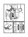
EBB
Instrucciones de montaje
Instruction leaflet
Notice de montage
Montageanweisungen
Montage-en gebruiksaanwijzing
Instruções de montagem
Istruzioni per l'installazione
Användar instruktion
Brugervejledning
Instrukcja obslugi
Návod
Инструкции по сборке
1
5
2
6
3
7
4
9
8
Fig.1
Fig.1B
3
6
7
Fig.2A
Fig.2B
N LA LB
Fig.4
Fig.3
EBB- S
N LA LB
N
Fig.5A
L
N LA LB
N
Fig.5B
L
N LA LB
N
Fig.6A
L
C
N LA LB
N
Fig.6B
L
REB
EBB- T
N L LS
N
Fig.7A
L
N L LS
N
Fig.7B
L
EBB- HT
N L LS
N
L
Fig.8A
N L LS
N
Fig.8B
L
30
A
15
2
T(min.)
N
L LS
Fig.9A
30
1 90
60
20
10 80
70
T(min.) HR(%)
N
L LS
Fig.9B
ENGLISH
EBB CENTRIFUGAL EXTRACTOR
EBB series extractors have been manufactured
according to strict production and quality control
standards such as ISO 9001. All the components
have been verified and all the devices have been
tested following assembly.
We recommend you to check the following points
when you receive this extractor:
1- Make sure you have received the right model
2- Make sure that the data on the nameplate are
appropriate to your needs: voltage, frequency,
speed, etc.
SAFETY RECOMMENDATIONS
The installation must be carried out in
accordance with current regulations in each
country.
- The installation must be carried out by a
qualified professional.
- The electrical installation must incorporate an
omnipolar switch with an opening between
contacts of at least 3 mm, appropriate for the load
and complying with current standards.
- In bathrooms, the device must be installed
outside the reach of any person taking a shower
or a bath and the switch must be installed outside
the bathroom.
- Do not use these fans in explosive or corrosive
atmospheres. If the EBB is working in a kitchen
where there is a boiler or any other kind of
combustion device that needs air to work, check
that the air inlets to the kitchen are sufficient.
- The extractor discharge cannot be connected to
a conduit for the evacuation of smoke from
devices worked by gas or any other fuel
- In the event of considerable humidity, you are
advised to install the discharge conduit
horizontally, with a slight outwards slant.
INSTALLATION
IMPORTANT: Before proceeding with the
installation and connection of the device,
make sure to disconnect the electricity
supply.
Figure 1A:
1- Front cover
2- Fan body
3- Front cover clip
4- Base frame
5- Connections cover
6- Slots
7- Retainers
8- Deflector
9- Discharge flange
- EBB series fans must be installed in an area that
is sheltered from meteorological conditions; they
can be assembled either in vertical or horizontal
position.
- The extractor is designed to be connected to a
100-mm diameter conduit
- Before assembling the device, check that the
turbine rotates freely.
For your extractor to work more efficiently:
- Do not use conduits whose diameter is less than
100 mm
- If a flexible conduit is used, stretch it out fully
- Do not place elbows right at the extractor
discharge
- Elbows should have as large a radius as
possible
Surface Assembly (fig. 2A):
1. Make a 105-mm diameter hole in the wall or
ceiling, making sure that the device fits in the area
you have planned for it.
2. Remove the front cover (1) of the fan body (2)
pressing the clips (3) carefully with a small
screwdriver (fig.1B).
3. The fan body (2) is secured to the base frame
(4) by means of 4 screws and 3 flanges. To
dismantle it, remove the 4 screws from the
corners and open the 3 flanges (7) by introducing
a small screw driver through the slots (6).
4. Using 4 screws and plugs that are appropriate
for the kind of wall, fix the base frame (4) on to the
surface, ensuring that the circular profile of the
frame coincides with the opening made, so that
the discharge nozzle can be introduced easily
subsequently.
5. Open the connections cover (5) of the fan
body and pass the cable through the hole
provided for this purpose on the bottom of the
terminal box.
6. Reassemble the fan body (2) on to the base
frame (4) by introducing it into the flanges and
securing it with the 4 screws.
7. Connect to the terminals passing the cable
through as indicated in figure. 3.
8. Follow the electrical diagram applying to the
EBB version that is being installed (fig. 5 to 8).
9. Close the connections cover (5) with the
screw.
10.Assemble the front cover (1) again, pressing
the upper and lower clips and pressing each
corner down to ensure that it fits properly in place.
11.Turn the extractor on to check that it works
properly.
Built-in assembly (fig. 2B):
1. Use the template to mark and cut the panel
into which the device will be installed. Read the
instructions given on the template carefully.
2. Follow steps 1, 2 and 3 of the Surface
Assembly Instructions.
3. With built-in assembly, the discharge can be
directed towards the side (fig. 4). To do this,
remove the discharge flange (3). Cut the
deflector (8) completely and put the discharge
flange back in the desired direction.
4. Open the connections cover (5) and pass the
cable through the hole provided for this purpose
on the bottom of the terminal box.
5. Connect a 100-mm diameter tube to the
discharge flange (9).
6. Secure the fan body (2) using 4 screws and
plugs that are appropriate for the kind of surface.
7. Connect to the terminals, passing the cable
through as indicated in figure 3.
8. Follow the electrical diagram applying to the
EEB version that is being installed (fig. 5 to 8)
9. Close the connections cover (5) with the
screw.
10.Assemble the front cover (1) again by
tightening the upper and lower clips and pressing
each corner to ensure that it fits properly in place.
11.Switch the extractor on to check that it is
working properly.
- If the device is used for more than 50 seconds
the timing is controlled automatically by the
device. It is proportional to the time of use (time of
use / x 2, with a maximum of 30 minutes).
Position 2': Timing set to 2 minutes
Position 15': Timing set to 15 minutes
Position 30': Timing set to 30 minutes
ELECTRICAL CONNECTION (fig. 5 to 8)
- Before working on the fan, make sure that it is
fully disconnected from the electricity supply,
even if it is switched off.
- Make sure that the voltage and frequency
values of the electricity supply are the same as
those indicated on the name plate of the device
(maximum voltage and frequency variation: 5%).
- EBBs are class II (double insulation) devices
and do not require earth connection
- Follow the connections diagram applying to the
version installed
Recommendations:
- In order to modify the factory settings, the
potentiometers situated beside the connections
cover (fig. 9B) will have to be operated. These
potentiometers are fragile and must be handled
with care.
- For correct humidity detection, the device must
be installed in an area in which there is good air
circulation.
- Do not change the humidity setting outside the
area in which the device is installed.
EBB version “S”
Basic version with two-speed motor, which can
also be voltage regulated. For this model proceed
according to one of the following diagrams:
Fig. 5A- Single-speed operation with an
independent switch.
Fig. 5B- F Single-speed operation using the same
switch as the light
Fig. 6A- 2-speed operation with a switch
Fig. 6B- Operation with an REB-type voltage
regulator
EBB version “T”
Models equipped with adjustable timing. The
timing enables the device to operate for the time
set, when the switch has been turned off (fig. 7A).
In timer mode, the EBB operates at slow speed.
ATTENTION: The device is timed to start up 50
seconds after being switched on, which
means that for the first 50 seconds it does not
work.
Fig. 7B Timer-based operation so that the device
starts up by means of the same switch as the
light.
To set this timer function (fig. 9A), turn the
potentiometer situated beside the connections
cover (5).
The device can be set to 4 different timer
positions:
Auto Position:
- If the device is used for less than 50 seconds,
the timing will not come into operation
EBB version “HT”
Models equipped with an electronic humidistat
that can be regulated between 60 and the 90%
RH (Relative Humidity %) and with timing that can
be set between 1 and 30 minutes.
When in the timer mode the EBB works at slow
speed.
Settings:
The extractors are preset to 60% RH for humidity
and 1 minute for timing.
- If the humidity level in the area is below 60% RH,
the extractor will not start up.
- If the humidity level in the area is above 60% RH,
the extractor will start up automatically.
- If the humidity level is always above 90% RH the
extractor will operate constantly.
- If you wish to modify the settings; that is,
maintain a humidity level of over 60% RH in the
area, turn the “%Hr” potentiometer clockwise.
- If you wish to increase the timer setting; that is,
increase the time during which the extractor
operates once the humidity level is under the set
level, turn the potentiometer “T min.“ clockwise.
ATTENTION: You should not attempt to adjust
the extractor settings when the extractor is in
timer mode. You must wait until the set time
has elapsed before adjusting the settings.
Operation
Case 1: In automatic working mode (fig. 8A) the
device switches on automatically at fast speed
when the humidity level in the area is above the
selected value. It stops when the humidity level
drops below this value and when the time set by
the timer has elapsed. When the device is in timer
mode, it works at slow speed.
Case 2: Automatic operation with possibility of
turning on the device by means of the light switch
(fig. 8B). Automatic operation similar to case 1 but
with the device will start up even if the humidity
level in the area is below the set value. In this
case, when the switch is turned off (the light is
switched off), the device continues to operate at
slow speed for the length of time set by the timer.
ATTENTION: When the relative humidity level
in the area is above the set value, automatic
operation prevails over manual operation;
that is, the device cannot be turned off by
means of the switch.
MAINTENANCE
IMPORTANT: Before carrying out any
maintenance operations, make sure to
disconnect the electricity supply.
You are advised to remove any dirt that has
accumulated in the 4 filters of the front cover (1) at
regular intervals. To do so, remove the front
cover as indicated in the “INSTALLATION”
section and hand wash with warm soapy water.
Make sure that the front cover is absolutely dry
before putting it back in place.
Clean the other parts with a cloth soaked in mild
detergent.
TECHNICAL ASSISTANCE
Should you observe any anomaly in the operation
of the device, contact an official authorised
service or the seller of the product.
If the device is handled by persons who are not
authorised by S&P, the guarantee will be
cancelled.
(S&P reserves the right to make changes
without prior notice.)