1
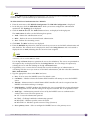
Summit WM Getting Started Guide
Software Version 5.1
Extreme Networks, Inc.
3585 Monroe Street
Santa Clara, California 95051
(888) 257-3000
(408) 579-2800
http://www.extremenetworks.com
Published: September 2008
Part number: 120428-00 Rev 02
AccessAdapt, Alpine, Altitude, BlackDiamond, EPICenter, ESRP, Ethernet Everywhere, Extreme Enabled, Extreme
Ethernet Everywhere, Extreme Networks, Extreme Standby Router Protocol, Extreme Turbodrive, Extreme Velocity,
ExtremeWare, ExtremeWorks, Essentials, ExtremeXOS, the Go Purple Extreme Solution, ScreenPlay, Sentriant,
ServiceWatch, Summit, SummitStack, Triumph, Unified Access Architecture, Unified Access RF Manager, UniStack,
the Extreme Networks logo, the Alpine logo, the BlackDiamond logo, the Extreme Turbodrive logo, the Summit
logos, the Powered by ExtremeXOS logo, and the Color Purple, among others, are trademarks or registered
trademarks of Extreme Networks, Inc. or its subsidiaries in the United States and/or other countries.
Adobe, Flash, and Macromedia are registered trademarks of Adobe Systems Incorporated in the U.S. and/or other
countries. AutoCell is a trademark of AutoCell. Avaya is a trademark of Avaya, Inc. Internet Explorer is a registered
trademark of Microsoft Corporation. Mozilla Firefox is a registered trademark of the Mozilla Foundation. sFlow is a
registered trademark of sFlow.org. Solaris and Java are trademarks of Sun Microsystems, Inc. in the U.S. and other
countries.
Specifications are subject to change without notice.
All other registered trademarks, trademarks, and service marks are property of their respective owners.
© 2007-2008 Extreme Networks, Inc. All Rights Reserved.
2
Summit WM Getting Started Guide, Software Version 5.1
Table of Contents
About this guide .............................................................................................................................. 7
Who should use this guide ...........................................................................................................7
What is in this guide ...................................................................................................................7
Formatting conventions................................................................................................................8
Document feedback ....................................................................................................................8
Chapter 1: Summit WM Controller, Access Points, and Software Solution........................................... 9
Conceptual model .......................................................................................................................9
Summit WM Controller ..........................................................................................................9
Web-based centralized management of Wireless APs ..........................................................9
Virtualized user segmentation ...........................................................................................9
Authentication and encryption ........................................................................................10
Intrusion detection ........................................................................................................10
Automatic assignment of IP addresses to the client devices...............................................10
Web authentication .......................................................................................................10
Wireless AP ........................................................................................................................11
Altitude AP ...................................................................................................................11
Outdoor AP ...................................................................................................................11
Altitude 802.11n AP .....................................................................................................12
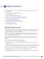
WDS ............................................................................................................................12
Summit WM Controller, Access Points, and Software Solution topology and network elements ....13
Discovery mechanism in Summit WM Controller, Access Points, and Software Solution..............14
Discovery mechanism between Wireless AP and Summit WM Controller..............................14
Discovery mechanism between mobility manager and mobility agents.................................14
DHCP in Summit WM Controller, Access Points, and Software Solution ....................................14
DHCP for Wireless APs ..................................................................................................15
DHCP for WM-AD ..........................................................................................................16
DHCP relay for WM-AD ..................................................................................................17
DHCP for traffic bridged locally at Wireless AP.................................................................18
Summit WM Controller’s physical description...............................................................................18
Summit WM200/2000 Controller front panel .........................................................................19
Summit WM200/2000 Controller data port cabling specification .......................................19
Summit WM200/2000 Controller LEDs ...........................................................................20
Summit WM200/2000 Controller’s LED states and Seven Segment Display (SSD) codes......20
Summit WM200/2000 Controller back panel .........................................................................22
Summit WM20 Controller front panel ....................................................................................23
Summit WM20 Controller data port cabling specification ..................................................23
Summit WM20 Controller’s LEDs....................................................................................24
Summit WM20 Controller’s LED states............................................................................24
Summit WM20 Controller back panel ....................................................................................25
Summit WM1000 Controller front panel ................................................................................25
Summit WM1000 Controller back panel ................................................................................26
Summit WM1000 Controller data port cabling specification ..............................................26
Summit WM1000 Controller LEDs ..................................................................................27
Summit WM100 Controller front panel ..................................................................................27
Summit WM100 Controller back panel ..................................................................................28
Summit WM Getting Started Guide, Software Version 5.1
3
Table of Contents
Summit WM100 Controller data port cabling specification ................................................28
Collecting information for installation..........................................................................................28
Chapter 2: Summit WM Controller configuration.............................................................................. 35
Accessing the Summit WM Controller for the first time .................................................................35
Connecting the Summit WM Controller to the enterprise network ...................................................39
Changing the administrator password ..........................................................................................39
Configuring the network time......................................................................................................39
Configuring the network time using the system’s time .............................................................40
Configuring the network time using the NTP ..........................................................................41
Applying a license key ...............................................................................................................41
Chapter 3: Physical ports configuration .......................................................................................... 43
Physical data ports overview .......................................................................................................43
Configuring physical data ports...................................................................................................44
Chapter 4: Routing Configuration.................................................................................................... 47
Configuring a static route ...........................................................................................................47
Viewing the forwarding table.................................................................................................48
Configuring the OSPF routing .....................................................................................................48
Enabling OSPF globally on the Summit WM Controller ............................................................49
Defining the global OSPF parameters ....................................................................................50
Confirming the ports are set for OSPF .............................................................................51
Chapter 5: Configuring DHCP, DNS and IAS services ....................................................................... 53
DHCP service configuration ........................................................................................................53
Configuring DHCP in Windows 2003 Server ...........................................................................53
Configuring DHCP in Red Hat Linux Server ............................................................................56
For Wireless AP subnet ..................................................................................................57
For WM-AD subnets (In Summit WM Controller it is configured as Use DHCP Relay)............57
IAS service configuration ...........................................................................................................58
Installing IAS on Windows 2003 Server.................................................................................58
Enabling IAS to authenticate users in active directory .............................................................58
Configuring IAS properties ...................................................................................................59
Configuring Summit WM Controller as IAS client ....................................................................61
Configuring Remote Access Policies......................................................................................61
DNS service configuration ..........................................................................................................64
Configuring DNS for internet access......................................................................................65
Configuring DNS for Wireless APs discovery ...........................................................................66
Chapter 6: Wireless AP configuration ............................................................................................. 67
Wireless AP overview .................................................................................................................67
Altitude AP.........................................................................................................................68
Outdoor AP.........................................................................................................................68
Altitude 802.11n AP ...........................................................................................................68
MIMO ..........................................................................................................................69
Channel bonding ...........................................................................................................70
Shortened guard interval ................................................................................................71
MAC enhancements.......................................................................................................71
4
Summit WM Getting Started Guide, Software Version 5.1
Table of Contents
Wireless AP’s default IP address and first-time configuration...................................................71
Configuring the Wireless APs for the first time .............................................................................72
Powering the Wireless APs ...................................................................................................74
Altitude AP ...................................................................................................................74
Outdoor AP ...................................................................................................................74
Altitude 802.11n AP .....................................................................................................74
Manually approving pending Wireless APs..............................................................................74
Assigning names to Wireless APs ................................................................................................75
Modifying Wireless APs’ properties..............................................................................................76
Configuring static IP address for Wireless APs..............................................................................77
Configuring VLAN tags for Wireless APs.......................................................................................80
Resetting the Wireless AP to its factory default settings ..........................................................81
Resetting the Altitude AP to its factory default settings. ....................................................81
Reset button (Hardware) ................................................................................................82
Resetting the Outdoor AP to its factory default settings .....................................................82
Resetting the Altitude 802.11n AP to its factory default settings .......................................83
Wireless AP’s LED states ...........................................................................................................83
Altitude AP LED status ........................................................................................................84
LEDs color codes...........................................................................................................84
Center LED ...................................................................................................................84
Left LED.......................................................................................................................85
Left and Right LEDs ......................................................................................................85
Composite view of the three LEDs ...................................................................................85
Outdoor AP LED status ........................................................................................................87
Altitude 802.11n AP LED status ....................................................................................88
LED color codes ............................................................................................................89
LED L1 ........................................................................................................................89
LEDs L3 and L4............................................................................................................89
LED L2 ........................................................................................................................90
Chapter 7: WM-AD configuration .................................................................................................... 91
WM-AD topology overview ..........................................................................................................91
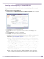
Creating and configuring a Routed WM-AD ..................................................................................93
Creating and configuring a Bridge Traffic Locally at WM WM-AD....................................................95
Creating and configuring a Bridge Traffic Locally at AP WM-AD .....................................................95
Creating and configuring WDS WM-AD ........................................................................................96
Assigning Wireless APs’ radios to WM-AD ....................................................................................96
To assign Wireless APs to a WM-AD: ...............................................................................96
Configuring authentication mechanism for WM-AD .......................................................................97
Configuring MAC-based authentication ..................................................................................98
Configuring Internal Captive Portal authentication ................................................................100
Configuring External Captive Portal authentication ...............................................................102
Configuring 802.1x authentication......................................................................................103
Configuring filtering rules.........................................................................................................103
Configuring filtering rules for filters in SSID network assignment ...........................................103
Configuring filtering rules for Exception filter .................................................................104
Configuring filtering rules for a Non-authenticated filter ..................................................104
To configure rules for the Non-authenticated filter..........................................................104
Configuring filtering rules for Default filter.....................................................................105
Configuring filtering rules for filters in AAA network assignment.............................................106
Summit WM Getting Started Guide, Software Version 5.1
5
Table of Contents
Configuring privacy for WM-AD .................................................................................................106
Configuring privacy for SSID network assignment .................................................................106
Configuring Static WEP................................................................................................106
Configuring WPA-PSK..................................................................................................107
Configuring privacy for AAA network assignment...................................................................109
Configuring Static WEP................................................................................................109
Configuring Dynamic WEP............................................................................................109
Configuring Wi-fi Protected Access (WPA v1 and WPA v2) privacy....................................109
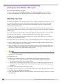
Chapter 8: Availability and Mobility configuration ......................................................................... 113
Availability overview ................................................................................................................113
Configuring availability feature .................................................................................................113
High-level overview of the availability configuration process.............................................113
Defining a WM-AD with the same SSID on both the Summit WM Controllers ...........................114
Assigning radios to WM-AD and confirming the Poll Timeout value on Altitude APs screen .......114
Assigning the Wireless APs to their home Summit WM Controller ...........................................115
Enabling availability pair, defining primary Summit WM Controller, and selecting security mode.....
116
Viewing the Wireless AP availability display .........................................................................117
Viewing the active Wireless APs report.................................................................................118
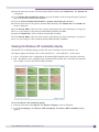
Mobility overview ....................................................................................................................118
Configuring mobility ................................................................................................................119
Configuring a Summit WM Controller as a mobility manager ..................................................119
Configuring a Summit WM Controller as a mobility agent ......................................................121
Viewing the Mobility Manager display ............................................................................121
Viewing Mobility Agent display......................................................................................122
Index .......................................................................................................................................... 123
6
Summit WM Getting Started Guide, Software Version 5.1
About this guide
The purpose of the Getting Started Guide is to assist you in deploying Extreme Networks® Summit®
WM Wireless LAN (WLAN) Solution by mapping preparation, installation, and configuration tasks into
a logical and efficient flow.
You can use this guide independently of other documents. However, if you are looking for detailed
information on any aspect of the system’s installation, configuration, or management, use this guide in
conjunction with the Summit WM User Guide.
This guide is based on the following product families:
●
Summit WM2000 Controller
●
Summit WM200 Controller
●
Summit WM20 Controller
●
Summit WM1000 Controller
●
Summit WM100 Controller
Who should use this guide
This guide is written for the users of Summit WM Wireless LAN (WLAN) Solution. You should be
familiar with computer networking concepts to use this guide.
What is in this guide
This contents in this guide are organized under the following chapters:
●
“About this guide”– Describes the purpose, the target audience and the architecture of this guide.
●
Chapter 1, “Summit WM Controller, Access Points, and Software Solution” – Captures the essential
concepts of the solution.
●
Chapter 2, “Summit WM Controller configuration”– Explains how to configure the Summit WM
Controller’s settings in order to make it operational.
●
Chapter 3, “Physical ports configuration”– Describes how to configure the Summit WM Controller’s
physical ports.
●
Chapter 4, “Routing Configuration”– Explains how to configure the static and OSPF routings on the
Summit WM Controller’s physical ports.
●
Chapter 5, “Configuring DHCP, DNS and IAS services”– Describes how to configure DHCP, DNS
and IAS services on Windows 2003 Server. In addition, the chapter explains how to configure DHCP
service on a Linux-based server.
●
Chapter 6, “Wireless AP configuration”– Explains how to configure and manage the Wireless APs
through the Summit WM Controller.
●
Chapter 7, “WM-AD configuration”– Describes how to create and configure WM-AD via the Summit
WM Controller.
Summit WM Getting Started Guide, Software Version 5.1
7
About this guide
●
Chapter 8, “Availability and Mobility configuration” – Explains how to configure availability and
mobility features via the Summit WM Controller.
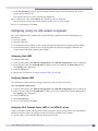
Formatting conventions
The document uses the following formatting conventions to make it easier to find information and
follow procedures:
●
Bold text is used to identify components of the management interface, such as menu items and
section of pages, as well as the names of buttons and text boxes.
●
●
Monospace font is used in code examples and to indicate text that you type.
●
●
For example: Click Logout.
For example: Type https://<WM-address>[:mgmt-port>]
The following symbols are used to draw your attention to additional information:
NOTE
Notes identify useful information such as reminders, tips, or other ways to perform a task.
CAUTION
Cautionary notes identify essential information, which if ignored can adversely affect the operation of your
equipment or software.
WARNING!
Warning notes identify essential information that if ignored can lead to personal injury or harm.
Document feedback
If you have any problems using this document, please contact your next level of support:
●
Extreme Networks® employees should contact the interactive Customer Engagement Team (i-CET).
●
Customers should contact the Extreme Networks Customer Support Center.
When you call, please have the following information ready. This will help us to identify the document
that you are referring to.
8
●
Title – Summit WM Getting Started Guide, Software Version 5.1.
●
Part Number – 120428-00 Rev 02.
Summit WM Getting Started Guide, Software Version 5.1
1
Summit WM Controller, Access Points, and
Software Solution
This chapter describes the essential concepts of Summit WM Controller, Access Points, and Software
Solution.
The topics in this chapter are organized as follows:
●
Conceptual model
●
Collecting information for installation
Conceptual model
The Summit WM Controller, Access Points, and Software Solution is an enterprise WLAN solution that
consists of the following components:
●
Summit WM Controller and Summit WM Software
●
Wireless AP
Summit WM Controller
The Summit WM Controller is a high-performance network device that provides several functions,
including centralized management and configuration of Wireless APs, user authentication, and
advanced radio frequency management.
The Summit WM Controller is driven by the Summit WM Software. The software resides on the
Summit WM Controller and provides an intuitive web-based interface — Summit WM Graphical User
Interface (GUI) — to enable you to manage the entire wireless network from a laptop, or a PC
connected to the network. A command line interface is also available to manage the wireless network.
The Summit WM Controller is a full-functioning dynamic router that aggregates and coordinates all
Wireless APs and manages client devices.
Some key features of the Summit WM Controller are provided in the following sections:
Web-based centralized management of Wireless APs
The Summit WM Controller enables you to monitor and manage Wireless APs from a centralized webbased interface called the Summit WM GUI. You can separately configure, enable, or disable each
Wireless AP from the Summit WM Controller using the Summit WM GUI.
Virtualized user segmentation
The Summit WM Controller allows you to create and manage unique WM Access Domain Services
(WM-AD) that enables you to group specific mobile users, devices and applications on the basis of
Summit WM Getting Started Guide, Software Version 5.1
9
Summit WM Controller, Access Points, and Software Solution
policy class in order to provide unique levels of service, access permissions, encryption, and device
authorization.
A WM-AD segment is a virtual network and each Wireless AP can support multiple WM-AD segments.
WM-AD optimizes the dynamic nature of WLAN mobility as WM-AD groups can follow users without
depending on the physical configuration of the network.
The following is the list of Summit WM Controllers and the number of WM-ADs they can support.
●
Summit WM2000 Controller: 64 WM-ADs
●
Summit WM200 Controller: 32 WM-ADs
●
Summit WM1000 Controller: 50 WM-ADs
●
Summit WM100 Controller: 32 WM-ADs
●
Summit WM20 Controller: 8 WM-ADs
Authentication and encryption
The Summit WM Controller and Wireless AP work together to support comprehensive authentication,
encryption, and intrusion detection capabilities. A range of robust security features based upon the
802.11 and WPA2 standards ensure that your network stays protected.
802.1X mechanism in conjunction with RADIUS and pre-shared key authentication ensure that only
authorized users can access the network.
Other features include Captive Portal for redirected web-based authentication.
Intrusion detection
The Summit WM Controller allows you to configure Wireless APs to detect rogue access points on the
network by scanning the radio frequency (RF) space at specific intervals. Scan results are then
forwarded to the Summit WM Controller; the Summit WM Controller processes and presents the data
centrally. Rogue detection data can be viewed via the Summit WM GUI.
Automatic assignment of IP addresses to the client devices
The Summit WM Controller has built-in DHCP server that assigns IP addresses to the client devices.
The Summit WM Controller is also capable of working with an external DHCP server.
Web authentication
The Summit WM Controller has a built-in Captive Portal capability that allows Web authentication
(Web redirection) to take place. The Summit WM Controller is also capable of working with external
Captive Portal.
10
Summit WM Getting Started Guide, Software Version 5.1
Wireless AP
Wireless APs are enterprise-class access points that deliver secure wireless access via the layer 3 tunnel
for enterprise deployments. They provide advanced RF capabilities, security, reliability and scalability.
The Wireless APs provide an unmatched level of flexibility and performance for complex, time-sensitive
functions including QoS, encryption and rogue AP detection.
The Wireless AP physically connects to a LAN infrastructure and establishes an IP connection with the
Summit WM Controller. The Wireless AP has no user interface — instead the Wireless AP is managed
through the Summit WM GUI. Global functions like configuration, roaming, security management, and
policy control are managed via the Summit WM GUI.
All communication between the Summit WM Controller and the Wireless AP is carried out using a
UDP-based protocol. The IP traffic, coming from the Wireless AP is encapsulated, and is directed to the
Summit WM Controller. The Summit WM Controller decapsulates the packets and routes them to the
appropriate destinations while managing sessions and applying policy.
The Wireless AP comes in the following three variants:
●
Altitude™ AP
●
Outdoor AP (Siemens brand of outdoor AP)
●
Altitude 802.11n AP
Altitude AP
The Altitude AP is available in the following two models:
●
Altitude 350-2i – Internal antenna, internal dual (multimode) diversity antennas
●
Altitude 350-2d – External antenna (dual external antennas), RP-SMA connectors
NOTE
Since the Altitude AP is meant for indoor environments, it is also referred to as Indoor AP.
Outdoor AP
The Siemens branded outdoor AP (OAP) can be managed by Summit WM controller. The following
models of Siemens branded Outdoor APs shall be managed by Summit WM. These are dual radio 11a/
b/g access points designed for outdoor and harsh environment use.
●
SEN 2650 (Internal antennas)
●
SEN 2660 (External antennas)
●
A&D W786-2HPW (Internal antennas- with Ethernet)
●
A&D W786-2HPW (Internal antennas- with Fiber Optic)
●
A&D W786-2HPW (External antennas- with Ethernet)
●
A&D W786-2HPW (External antennas- with Fiber Optic)The Altitude AP is meant for indoor
environments. It can be mounted on walls or ceilings, using special brackets, and can be kept
completely out of sight.
Summit WM Getting Started Guide, Software Version 5.1
11
Summit WM Controller, Access Points, and Software Solution
The Outdoor AP enables you to extend your Wireless LAN beyond the confines of indoor locations.
They are resistant to harsh outdoor conditions and extreme temperatures. Using the advanced wireless
distribution feature of Summit WM Wireless LAN, the Outdoor AP can extend your Wireless LAN to
outdoor locations without Ethernet cabling. A mounting bracket is available to enable quick and easy
mounting of the Outdoor APs to walls, rails and poles.
NOTE
Although the Outdoor AP is meant for outdoor environments, it can also be deployed in indoor environments.
The Outdoor AP supports the 802.11a, 802.11g and full backward compatibility with legacy 802.11b
devices.
NOTE
Since the Outdoor AP is meant for outdoor environments, it is also referred to as Outdoor AP.
NOTE
The configuration process is same for the Altitude AP and the Outdoor AP, and is done via the Summit WM
Controller.
Altitude 802.11n AP
The Altitude 802.11n AP is an IEEE 802.11n (draft)-compliant access point that offers significant increase
in data throughput and coverage range without additional bandwidth or transmit power. With both 2.4
GHz and 5 GHz 802.11n (draft) standard radio modules, the 802.11n AP delivers total data rates of up
to 300 Mbps. Given that the improved throughput of 300 Mbps will be spread over a number of
simultaneous users, the performance of 802.11n AP will be close to that of a wired 100 Mbps Ethernet
connection — the standard for desktop connectivity. With the 802.11n AP, the mobile users get the
experience similar to wired networks while accessing high-bandwidth data, voice, and video
applications. For more information, see “Altitude 802.11n AP” on page 68.
The Altitude 802.11n AP is available in the following two models:
●
Altitude 450 – 3 internal antennas
●
Altitude 451 – 3 internal antennas, RP-SMA connectors
WDS
A Wireless Distribution System (WDS) enables you to expand the wireless network by interconnecting
the Wireless APs through wireless links in addition to the traditional method of interconnecting
Wireless APs via a wired network. The WDS deployment is ideally suited for locations, where installing
ethernet cabling is too expensive, or physically impossible.
12
Summit WM Getting Started Guide, Software Version 5.1
Summit WM Controller, Access Points, and Software Solution
topology and network elements
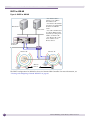
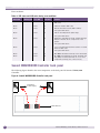
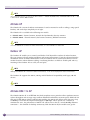
The following figure illustrates a typical configuration with a single Summit WM Controller and two
Wireless APs, each supporting a wireless device. A RADIUS server on the network provides user
authentication, and a DHCP server assigns IP addresses to the Wireless APs. Network inter-connectivity
is provided by the infrastructure routing and switching devices.
Figure 1: Summit WM Wireless LAN topology
RADIUS
Server
DHCP
Server
Control & Routing
• The Summit WM
Controller authenticates
wireless user
• The Summit WM
Controller forwards the IP
packet to the wired
network
Tunnelling
• Wireless AP sends data
traffic to the Summit WM
Controller through the
UDP tunnel called CTP
• The Summit WM
Controller controls the
Wireless APs through the
CTP tunnel.
Summit WM
Controller
Wireless AP
Wireless AP
Wireless
Devices
The Summit WM Controller supports the following network elements.
●
RADIUS Server (Remote Access Dial-in User Service) – An authentication server that assigns and
manages ID and Password protection throughout the network. The RADIUS server system can be
set-up for certain standard attributes such as filter ID, and for the vendor specific attributes (VSAs).
The Summit WM Controller supports external RADIUS server.
●
DHCP Server (Dynamic Host Configuration Protocol) – A server that assigns the IP addresses,
gateways, and subnet masks dynamically. The external DHCP server depicted in Figure 2-1 is
primarily utilized to provide addresses to infrastructure equipment such as APs. The IP addresses to
the mobile devices are provided by the built-in DHCP server of Summit WM Controller. You can
also configure the Summit WM Controller to relay DHCP requests to the external DHCP server.
●
SLP (Service Location Protocol) – A service discovery protocol that allows computers and other
devices to find services in a local area network without prior configuration. The client applications
Summit WM Getting Started Guide, Software Version 5.1
13
Summit WM Controller, Access Points, and Software Solution
are user agents and services that are advertised by a service agent. In larger installations, a directory
agent collects information from service agents and creates a central repository. SLP is one of the
several modes that the Summit WM Controller uses to discover the Wireless APs.
●
Domain Name Server – A server that translates the domain names into IP addresses. The DNS is
used as an alternative mechanism for the automatic discovery process. The Summit WM Controller,
its software, and the APs rely on the DNS for Layer 3 deployments. In addition, DNS is utilized for
the static configuration of APs. The Summit WM Controller can be registered in DNS to provide
DNS assisted AP discovery.
Discovery mechanism in Summit WM Controller, Access Points,
and Software Solution
The Summit WM Controller, Access Points, and Software Solution provides auto-discovery capabilities
between the following components:
●
Wireless APs and Summit WM Controller
●
Mobility manager and mobility agents (For more information, see Chapter 8, “Availability and
Mobility configuration.”)
Discovery mechanism between Wireless AP and Summit WM Controller
The Wireless APs discover the Summit WM Controller by one of the following modes:
●
SLP (Multicast and Unicast) – For more information, see SLP’s description in “Summit WM
Controller, Access Points, and Software Solution topology and network elements” on page 13.
●
DNS – For more information, see Domain Name Server’s description in “Summit WM Controller,
Access Points, and Software Solution topology and network elements” on page 13.
●
Static IP address configuration – Summit WM Controller’s IP address is defined in Wireless AP
configuration. For more information, see “Configuring static IP address for Wireless APs” on
page 77.
Discovery mechanism between mobility manager and mobility agents
The mobility agents discover the mobility manager by one of the following modes:
●
SLP with DHCP Option 78 – The mobility agent on each Summit WM Controller discovers the
address of the mobility manager using DHCP Option 78.
●
Direct IP address option – Defined while configuring the mobility agent. By explicitly defining the
manager’s IP address while configuring the agents, enables the manager and agents to find each
other directly without using the SLP discovery mechanism.
DHCP in Summit WM Controller, Access Points, and Software
Solution
DHCP usage has four scenarios in Summit WM Controller, Access Points, and Software Solution:
14
●
DHCP for Wireless APs
●
DHCP for WM-AD
Summit WM Getting Started Guide, Software Version 5.1
●
DHCP relay for WM-AD
●
DHCP for traffic bridged locally at Wireless AP
The following sections explain the four scenarios with the help of graphical illustrations.
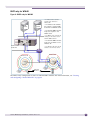
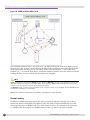
DHCP for Wireless APs
Figure 2: DHCP for Wireless APs
* The Wireless AP
requests an IP address
from the external DHCP
server.
DNS Server
DHCP Server
* The DHCP server
responds by sending
the IP address to the
Wireless AP.
Summit WM
Controller
Wireless AP
Wireless AP
Wireless
Devices
You can use Windows 2003 server, amongst others, for deploying DHCP service for Wireless APs. For
more information, see “DHCP service configuration” on page 53.
Summit WM Getting Started Guide, Software Version 5.1
15
Summit WM Controller, Access Points, and Software Solution
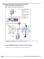
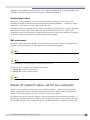
DHCP for WM-AD
Figure 3: DHCP for WM-AD
* The wireless device
requests an IP address
from Wireless AP.
* The Wireless AP forwards
the request to Summit WM
Controller via WM-AD
tunnel.
DNS Server
DHCP Server
* The built-in DHCP server
in Summit WM Controller
responds by sending the IP
address to Wireless AP.
* The Wireless AP sends
the IP address to the
wireless device.
Summit WM
Controller
Wireless AP
Wireless AP
Wireless
Devices
The DHCP configuration for WM-AD is done via Summit WM Controller. For more information, see
“Creating and configuring a Routed WM-AD” on page 93.
16
Summit WM Getting Started Guide, Software Version 5.1
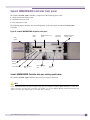
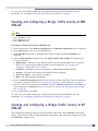
DHCP relay for WM-AD
Figure 4: DHCP relay for WM-AD
* A wireless device sends a
request for IP address to
Wireless AP.
DNS
Server
DHCP
Server
* The Wireless AP forwards
the request to Summit WM
Controller via WM-AD tunnel.
* The Summit WM Controller
relays the request to the
DHCP server.
* The DHCP server responds by
sending the IP address to the
Summit WM Controller.
* The Summit WM Controller
relays the IP address to the
Wireless AP.
Summit WM
Controller
* The Wireless AP sends the IP
address to the wireless device.
Wireless AP
Wireless AP
Wireless
Devices
The DHCP relay configuration is done via Summit WM Controller. For more information, see “Creating
and configuring a Routed WM-AD” on page 93.
Summit WM Getting Started Guide, Software Version 5.1
17
Summit WM Controller, Access Points, and Software Solution
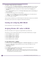
DHCP for traffic bridged locally at Wireless AP
Figure 5: DHCP for traffic bridged locally at Wireless AP
DNS
Server
* A wireless device sends a
request for IP address to
Wireless AP.
* The Wireless AP forwards
the request to the DHCP
server.
* The DHCP server responds
by sending the IP address to
the Wireless AP.
* The Wireless AP sends
the IP address to the
wireless device.
Summit WM
Controller
Wireless AP
Wireless AP
DHCP
Server
Wireless
Devices
The DHCP relay configuration is done via Summit WM Controller. For more information, see “Creating
and configuring a Bridge Traffic Locally at AP WM-AD” on page 95.
Summit WM Controller’s physical description
This section provides a physical description of the Summit WM Controller.
18
Summit WM Getting Started Guide, Software Version 5.1
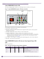
Summit WM200/2000 Controller front panel
The Summit WM200/2000 Controller is composed of the following three cards:
●
Media/Persistent Storage Card
●
Network Processor Card
●
Host Supervisor Card
The following figure identifies the main components on the front panel of Summit WM200/2000
Controller.
Figure 6: Summit WM200/2000 Controller front panel
Network Processor
card
Data
ports
LED
lights
Compact
Flash slot
Media/Persistent
storage card
Reset
switch
LCT switch
Management
port
Host Controller
card
Console
port
Summit WM200/2000 Controller data port cabling specification
The Summit WM200/2000 Controller data ports have copper connectors.
NOTE
If your infrastructure does not allow a copper connection, you should get a Gigabit Media Converter to convert the
copper connection to a fibre optic connection. For example, you can use Netgear GC102 converter that receives the
copper connection and outputs traffic via the fibre optic connector.
Summit WM Getting Started Guide, Software Version 5.1
19
Summit WM Controller, Access Points, and Software Solution
Summit WM200/2000 Controller LEDs
The Summit WM200/2000 Controller has five LED lights and two switches on its front panel.
Figure 7: Summit WM200/2000 Controller’s LED lights and switches
ACT LED
Seven-Segment
Display
Reset
Switch
RUN
LED
ERROR
LED
LCT Switch
WARNING
LED
INT LED
The description of the LED states and switches is provided below:
●
Reset Switch – Reboots the system.
●
RUN LED – Indicates the CPU’s initialization has completed and the system is ready to provide
application level services.
●
ACT LED – Indicates the system’s software is in active running state.
●
WARNING/ERROR LEDs – Indicate a problem in the running state of the system.
●
Whenever either of the alarm LEDs is lit, the seven-segment display provides the corresponding
code point for the error indication. When the system is fully active and running, the console
displays the letter A as seen in Figure 7.
●
LCT Switch – The LCT button is used during the manufacturing process and is inactive otherwise.
●
INT LED – Not used in the current release.
Summit WM200/2000 Controller’s LED states and Seven Segment Display (SSD)
codes
Firmware initialization
:
Table 1: LED states and SSD codes during firmware initialization
Active LED
20
SSD Codes
Condition
Green
Warning LED
Error LED
0
The processor has started; and the firmware has
taken control.
Green
3
The Host Supervisory Card has failed to download
Bootloader from Flash.
Green
4
The system is checking firmware consistency.
Summit WM Getting Started Guide, Software Version 5.1
Table 1: LED states and SSD codes during firmware initialization (Continued)
Active LED
Warning LED
Error LED
SSD Codes
Condition
Green
5
The system is formatting memory.
Green
6
The system is initializing load device.
Note: If the SSD code is stuck at 6 for more than
a minute, it implies that the Network Processor
Card is installed in wrong slot.
Green
9
The system is loading subsystem.
Green
b
The system is starting the operation system. The
system is active.
NOTE
Although the Active LED will be lit Green during the firmware initialization, this LED state is irrelevant to the SSD
display or the condition. You must ignore the LED state during the firmware initialization.
Application initialization:
Table 2: LED states and SSD codes during application initialization
Active LED
Warning LED
Error LED
SSD Code
Condition
Green
0
Application initialization started.
Green
1
Forwarding Engine initialization complete.
Application initialization.
Green
A
Application initialization complete. System active.
Green
H
System halted. Administrator requested halting of
system.
Warning conditions:
Table 3: LED states and SSD codes during warning conditions
Active LED
Warning LED
SSD Code
Condition
Green
Yellow
Error LED
1
High temperature reached.
Green
Yellow
2
Fan unit failure. Rotation counter indicates zero
speed for one of the lateral trays. May be the result
of fan tray removal.
Green
Yellow
3
Power supply failure. Failed to detect one of the
power supplies. May be the result of the fan tray
removal of one of the power supplies.
Green
Yellow
4
FDD low sector count (40 backup sectors
remaining).
Green
Yellow
5
FDD extremely low sector count (20 backup sectors
remaining)
Summit WM Getting Started Guide, Software Version 5.1
21
Summit WM Controller, Access Points, and Software Solution
Error conditions:
Table 4: LED states and SSD codes during error conditions
Active LED
Warning LED
Error LED
SSD Code
Condition
Green
Red
1
Failed to identify FDD. Possibly due to removal of
FDD card.
Green
Red
2
Failed to initialize NPE card.
Green
Red
3
Critical threshold reached (95C for NPE).
Green
Red
4
The system will reboot.
Full fan assembly failure (both trays).
The system will reboot.
Green
Red
5
Application initialization failure. Startup manager
failed to initialize all the components of the
system.
The system will reboot.
Green
Red
6
Lost connectivity with ethernet interface. Possible
failure of NPE card.
Green
Red
7
MF 1000 card failure. Backup sectors exhausted.
Green
Red
8
NP 4000 card initialization failure. Firmware self
test (BIST) has detected failure in one or more
components (memory, bus, interconnects)
The system will reboot.
Summit WM200/2000 Controller back panel
The following figure identifies the main components on the back panel of Summit WM200/2000
Controller.
Figure 8: Summit WM200/2000 Controller back panel
Redundant
Power Supply
Power Switches
22
Summit WM Getting Started Guide, Software Version 5.1
NOTE
The hardware for the Summit WM200 Controller and the Summit WM2000 Controller are identical. For more
information, see “Summit WM200/2000 Controller front panel” on page 19 and “Summit WM200/2000 Controller
back panel” on page 22.
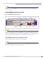
Summit WM20 Controller front panel
Figure 9: Summit WM20 Controller front panel
LAN Ports
Hot Swap Lever
Management
USB Server
Reset Button
USB Control
LEDs
Power Switch
NOTE
The hot swap button’s operation is not supported in the current release. Pulling the hot swap button to open position
will not affect the normal operation if the Summit WM20 Controller is already running. However, if you attempt to
reboot the Summit WM20 Controller with the hot swap button in open position, the controller will fail to boot.
If you pull the hot swap button to open position while the Summit WM20 Controller is in operation, the fourth LED
from the top will light up. For more information, see “Summit WM20 Controller’s LEDs” on page 24.
Summit WM20 Controller data port cabling specification
The Summit WM20 Controller’s data ports have copper connectors.
NOTE
If your infrastructure does not allow the copper connection, you must get a Gigabit Media Converter to convert the
copper connection to a fibre optic connection. For example, you can use Netgear GC102 converter that receives the
copper connection and outputs traffic via the fibre optic connector.
Summit WM Getting Started Guide, Software Version 5.1
23
Summit WM Controller, Access Points, and Software Solution
Summit WM20 Controller’s LEDs
The Summit WM20 Controller has four lights on its front panel.
Figure 10: Summit WM20 Controller LED lights
Activity LED
Status LED
HDD Activity LED
Hot Swap LED
The functional definitions of the Summit WM20 Controller’s LEDs are provided below:
●
ACTIVITY LED – Indicates the CPU activity, including the amount of traffic carried to and from the
Wireless APs.
●
STATUS LED – Indicates the normal state of the Summit WM Controller as seen by the system’s
software. This LED covers all stages of the Summit WM Controller, ranging from restarting, to
shutting-down. As long as the Summit WM Controller is running normally, this LED will remain lit.
●
HDD Activity LED – Is hardware controlled to report Hard Drive Device (HDD) activity.
●
Hot Swap LED – Indicates that the hot swap lever on the Summit WM Controller has been pulled.
For information, see “Summit WM20 Controller front panel” on page 23.
NOTE
The hot swap lever is not enabled in the current release. Pulling the hot swap lever will not affect the normal
operation if the Summit WM20 Controller is already running. However, if you attempt to reboot the Summit WM20
Controller with the hot swap lever pulled out, the controller will fail to reboot. If you pull the hot swap lever while
the Summit WM20 Controller is in operation, the Hot Swap LED will light up.
Summit WM20 Controller’s LED states
The description of the Summit WM20 Controller’s LED states is provided below.
Table 5: Summit WM20 Controller’s LED states and their description
24
Status LED
Activity LED
Condition
Blinking Amber
Green
Power up (BIOS, POST)
Off
Green
System Booting (Failed to boot)
Off
Green
Startup Manager: Task Started
Summit WM Getting Started Guide, Software Version 5.1
Table 5: Summit WM20 Controller’s LED states and their description
Status LED
Activity LED
Condition
Solid Amber
Blinking Amber
Startup Manager: Task Completes Startup — All Components Active
Solid Amber
Blinking Green
A Component Fails to Start or Needs Restarting (Startup Manager Task
Retrying That Component)
Green
Blinking Red
Possible Hardware Failure (No More Retries)
Solid Red
Off
A Component Fails (No More Retries)
Blinking Red
Off
System About To be Reset By Watchdog
Solid Red
Solid Red
System Shutdown / Halt (Requires Manual Reboot)
NOTE
LED 3 – HDDActivity LED – Orange/Amber
• HDDActivity LED is off when HDD is not in use
• HDDActivity LED is on when HDD is in use
LED 4 – Hot Swap LED – Blue
• Solid Blue when the hot swap button is pulled out
Summit WM20 Controller back panel
Figure 11: Summit WM20 Controller back panel
Power Supply
Summit WM1000 Controller front panel
The Summit WM1000 Controller doesn’t have any component on the front panel except two LED lights.
These two LED lights are:
●
STATUS LED – For more information, see the STATUS LED description in “Summit WM1000
Controller back panel” on page 26.
●
ACTIVITY LED – For more information, see the ACTIVITY LED description in “Summit WM1000
Controller back panel” on page 26
These two LED lights are also located on the back panel of the Summit WM1000 Controller.
Summit WM Getting Started Guide, Software Version 5.1
25
Summit WM Controller, Access Points, and Software Solution
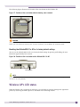
Summit WM1000 Controller back panel
The following figure identifies the main components on the back panel of Summit WM1000 Controller.
Figure 12: Summit WM1000 Controller back panel
Data Ports
Power Switch
Redundant Power Supply
Management Port
Console Port
LED Lights
NOTE
The Summit WM1000 Controller may have a standard power supply (one power supply) or a redundant power supply
(two power supplies).
Summit WM1000 Controller data port cabling specification
The data ports have MT-RJ fiber optic connectors. Depending upon your network infrastructure, you
must get any one of the following cables:
●
MT-RJ connector to MT-RJ connector
●
MT-RJ connector to SC connector
●
MT-RJ connector to LC connector
●
MT-RJ connector to any other connector that is appropriate for your infrastructure
NOTE
If your infrastructure does not allow the optic fiber connection, you must get a Gigabit Media Converter to convert
the fiber connection to a copper Gigabit connection. For example, you can use Netgear GC102 converter that
receives the fiber connection and outputs traffic via the RJ45 copper port (Unshielded Twisted Pair - UTP).
26
Summit WM Getting Started Guide, Software Version 5.1
Summit WM1000 Controller LEDs
The Summit WM1000 Controller has three LED lights on its back panel.
Figure 13: Summit WM1000 Controller LED Lights
Link-up LED
Status LED
Activity LED
The description of the LED states is provided below:
●
LINK-UP LED – Displays the link status of management port Ethernet link as seen by the system’s
software. This LED is located only on the back panel of the Summit WM1000 Controller.
●
STATUS LED – Indicates the normal state of the Summit WM Controller as seen by the system’s
software. This LED covers all stages of the Summit WM Controller, ranging from restarting, to
shutting-down. As long as the Summit WM Controller is running normally, this LED will remain lit.
The STATUS LED is located on the back panel as well as the front panel.
●
ACTIVITY LED – Indicates the amount of traffic carried to and from the Wireless APs. The
ACTIVITY LED is located on the back panel as well as the front panel.
Summit WM100 Controller front panel
The Summit WM100 Controller does not have any component on the front panel except two LED lights.
The description of the LED states is provided below:
●
STATUS LED– For more information, see the STATUS LED description in “Summit WM1000
Controller back panel” on page 26.
●
ACTIVITY LED – For more information, see the ACTIVITY LED description in “Summit WM1000
Controller back panel” on page 26.
NOTE
The STATUS LED is located on the back panel as well as the front panel of the Summit WM100 Controller.
Summit WM Getting Started Guide, Software Version 5.1
27
Summit WM Controller, Access Points, and Software Solution
Summit WM100 Controller back panel
The following figure identifies the main components on the back panel of Summit WM100 Controller.
Figure 14: Summit WM100 Controller back panel
Power Switch
Power Supply
Data Ports
Console Port
Management Port
LED Lights
NOTE
The Summit WM100 Controller has the same number of LED lights on the back panel as the Summit WM1000
Controller. The LED description of their state is also identical to WM100. For information on Summit WM100
Controller LEDs’ states, see the descriptions of STATUS LED and ACTIVITY LED in “Summit WM1000 Controller
back panel” on page 26.
NOTE
Summit WM100 Controller may have a standard power supply (one power supply) or a redundant power supply (two
power supplies).
Summit WM100 Controller data port cabling specification
The Summit WM100 Controller data ports have copper connectors.
NOTE
If your infrastructure does not allow the copper connection, you must get a Gigabit Media Converter to convert the
copper connection to a fibre optic connection. For example, you can use Netgear GC102 converter that receives the
copper connection and outputs traffic via the fibre optic connector.
Collecting information for installation
You should use the following table to document all the pertinent information about the Summit WM
Controller before starting the installation process.
28
Summit WM Getting Started Guide, Software Version 5.1
Some of the information listed in the table may not be relevant to your network configuration. You
should only record the information that is pertinent to your network configuration.
Table 6: Information gathering table
Configuration data
Description
Accessing the
Summit WM
Controller for the
first time
• Unused IP address in the 192.168.10.0/24 subnet – This IP
address must be assigned to the Ethernet port of your
laptop computer. You can use any IP address between
192.168.10.2 and 192.168.10.255.
Your entry
• Factory default IP address of Summit WM Controller – The
factory default IP address is https://192.168.10.1:5825.
You must type this IP address in the address bar of your
Web browser when you access the Summit WM Controller
for the first time.
• Login Information – The login information is as follows:
> User Name: admin
> Password: abc123
Management
Port information
• Hostname – Specifies the name of the Summit WM
Controller.
• Domain – Specifies the IP domain name of the enterprise
network.
• Management IP Address – The new IP address for the
Summit WM Controller’s management port. Change the
value in this text box to the IP address assigned to the
Summit WM Controller’s management port by your
network administrator.
• Subnet Mask – The subnet mask for the IP address to
separate the network portion from the host portion of the
address (typically 255.255.255.0)
• Management Gateway – The default gateway of the
network.
• Primary DNS – The primary DNS server used by the
network.
• Secondary DNS – The secondary DNS server used by the
network.
Hardware
information
• MAC Address – MAC address of the Summit WM
Controller’s management port
• Serial # – The Summit WM Controller’s serial #.
License Key (File)
An .xml file that is provided along with the product. This file
must be applied to the product to enable all the
functionalities.
Summit WM Getting Started Guide, Software Version 5.1
29
Summit WM Controller, Access Points, and Software Solution
Table 6: Information gathering table (Continued)
Configuration data
Description
Your entry
Data Ports
information
• IP address – IP address of the physical ethernet port.
• Subnet mask – Subnet mask for the IP address, which
separates the network portion from the host portion of
the address (typically 255.255.255.0).
• MTU – The maximum transmission unit or maximum
packet size for this port. The default setting is 1500. If
you change this setting, and are using OSPF, you must
make sure that the MTU of each port in the OSPF link
matches.
• Function – The port’s function.
> Host Port – A port for connecting Wireless APs with no
dynamic routing.
> Third-party AP Port – A port to which the third-party AP
is connected.
> Router Port – A port that connects to an upstream,
next-hop router in the network.
• VLAN ID – The ID of the VLAN to which the AP is
connected.
Static Routing
Static IP address – The static IP address that is assigned to
the Summit WM Controller when it is configured for static
routing.
OSPF Routing
• Router ID – The router ID is its own IP address.
• Area ID of OSPF – Id of OSPF’s area. 0.0.0.0. is the main
area in OSPF.
• OSPF Authentication Password – If you select
Authentication type as Password, then you will need a
password.
DHCP Service
• IP address range – This is the range from which the IP
address will be distributed across the network.
> Start IP address – This is the start IP address of the
range.
> End IP address – This is the end IP address of the
range.
• Lease duration – The DHCP server assigns a client an IP
address for a given amount of time. The amount of time
for which the IP address can be given is called lease
duration.
> Days – The number of days for which the lease can be
given.
> Hours – The number of hours for which the lease can
be given.
> Minutes – The number of minutes for which the lease
can be given.
30
IP Address for
installing DHCP
service
IP Address – If you are using WM-AD, you will need the WMAD’ IP address.
WM-AD gateway for
installing DHCP
service
WM-AD gateway – If you are using WM-AD, you will need the
WM-AD gateway.
If you are not using WM-AD, you will need the Summit WM
Controller’s IP address.
Summit WM Getting Started Guide, Software Version 5.1
Table 6: Information gathering table (Continued)
Configuration data
Description
Domain name for
installing DHCP
service
Domain name – Your organization’s domain name.
Windows 2003
Server’s IP address
IP address – The IP address of Windows 2003 Server.
SLP DA’s IP address
Hexa values of SLP DA’s IP address – The Wireless APs use
the SLP DA to discover the Summit WM Controller.
Your entry
The mobility agents use the SLP DA to discover the mobility
manager. The dotted decimal values of the SLP DA’s IP
address.
Internet Protocol
configuration for
DNS Service in
Windows 2003
server
• Static IP address – Windows 2003 server’s static IP
address.
• Subnet Mask – Subnet mask of Windows 2003 server’s
static IP address.
• Gateway – Windows 2003 server’s gateway.
• ISP’s IP address – Your ISP’s (Internet Service Provider)
IP address.
• IP address – Summit WM Controller’s IP address.
Port information for
installing IAS in
Windows 2003
server
• Authentication Port – Summit WM Controller’s port # used
to access the IAS service.
• Accounting Port – Type the Summit WM Controller’s port
# that is used to access the accounting service.
The values you record here should match what you define in
the Port text box of Auth section in the Acc & Acct tab of
Summit WM Controller’s WM-AD screen.
Wireless AP’s
properties
• Summit WM Controller’s Port # – Summit WM Controller’s
ethernet port to which the Wireless AP is connected.
• Country – The country where the Wireless AP operates.
• Serial # – A unique identifier that is assigned during the
manufacturing process of the Wireless APs.
• Hardware version – The current version of the Wireless AP
hardware.
• Application version – The current version of the Wireless
AP software.
• VLAN ID – The ID of the VLAN on which the Wireless AP
operates.
Local DHCP Server
In Routed WM-AD
• Gateway – The Summit WM Controller advertises this
address to the wireless devices when they sign on and
get a dynamic IP address. The gateway corresponds to
the IP address that is communicated to mobile users.
• Subnet mask – Subnet mask for the gateway IP address to
separate the network portion from the host portion of the
address (typically 255.255.255.0).
• Address range – The range from which the IP addresses
are provided to the wireless devices that use the WM-AD.
• External enterprise domain name – The external enterprise
domain name.
• DNS Server IP address – The IP address of the domain
name server on the enterprise network.
Summit WM Getting Started Guide, Software Version 5.1
31
Summit WM Controller, Access Points, and Software Solution
Table 6: Information gathering table (Continued)
Configuration data
Description
Your entry
DHCP Relay in
Routed WM-AD
• Gateway – The Summit WM Controller advertises this
address to the wireless devices when they sign on and
get a dynamic IP address. The gateway corresponds to
the IP address that is communicated to mobile users.
• Subnet mask – Subnet mask for the gateway IP address to
separate the network portion from the host portion of the
address (typically 255.255.255.0).
• DHCP Server IP address(es) – IP addresses of the external
DHCP servers on the enterprise network.
Next Hop Routing for
Routed WM-AD
• Next hop IP address – The next-hop IP identifies the
target device to which all WM-AD (user traffic) will be
forwarded to. Next-hop definition supersedes any other
possible definition in the routing table.
• OSPF routing cost – The OSPF cost value provides a
relative cost indication to allow upstream routers to
calculate whether or not to use the Summit WM
Controller as a better fit, or lowest cost path to reach the
devices in a particular network. The higher the cost, the
less likely that the Summit WM Controller will be chosen
as a route for traffic, unless that Summit WM Controller
is the only possible route for that traffic
VLAN Information for
Bridge Traffic Locally
at WM WM-AD
• VLAN ID – The ID # of VLAN that is mapped to a Summit
WM Controller interface.
• Interface – The name of the interface to which the VLAN
is mapped.
• Interface IP address – The interface’s IP address.
• Mask – The subnet mask of the WM-AD.
VLAN ID for Bridge
traffic locally at AP
WM-AD
• VLAN ID – The ID #of VLAN that is mapped to a Summit
WM Controller interface.
Authentication and
Accounting
information for
captive portal
configuration
• Port – Used to access the RADIUS server. The default is
1812.
• # of Retries – The number of times the Summit WM
Controller will attempt to access the RADIUS server.
• Timeout – The maximum time for which Summit WM
Controller will wait for a response from the RADIUS
server before making a re-attempt.
• NAS Identifier – A RADIUS attribute that identifies the
server responsible for passing information to the
designated servers and then acting on the response
returned. This is optional.
32
Summit WM Getting Started Guide, Software Version 5.1
Table 6: Information gathering table (Continued)
Configuration data
Description
Internal captive
portal settings
information
• Login Label – The text that will appear as a label for the
user name.
Your entry
• Password Label – The text that will appear as a label for
the user password text box.
• Header URL – The URL of the file to be displayed in the
header of the Captive Portal screen.
• Footer URL – The URL of the file to be displayed in the
footer of the Captive Portal screen.
• Message – The message that you type in this text box will
be displayed above the Login text box to greet the user.
You can type a message, explaining why the Captive
Portal screen is used and the instructions for the user.
• Replace Gateway IP with FQDN – If you are using FQDN
(Fully Qualified Domain Name) as the gateway address,
document the FQDN.
• Default Redirection URL – The URL to which the wireless
devices will be directed after authentication.
Shared Secret
Password for external
captive portal
configuration
Password – This password encrypts the information
exchanged between the Summit WM Controller and the
external Captive Portal server.
MAC-based
authentication
information
• Port – The port used to access the RADIUS server. The
default is 1812.
• # of Retries – Number of times the Summit WM
Controller will attempt to access the RADIUS server.
• Timeout – The maximum time for which Summit WM
Controller will wait for a response from the RADIUS
server before making a re-attempt.
• NAS IP Address – IP address of the network access server
(NAS).
Exception filter rules
information
IP/subnet – The destination IP address. You can also specify
the IP range, a port designation or a port range on the IP
address here.
Static WEP privacy
information
• WEP Key Length – Size of a WEP key.
WPA-PSK privacy
information
• Broadcast re-key interval – The time interval (in seconds)
after which you want the broadcast encryption key to be
changed automatically. The default is 3600.
• Strings – This is the secret WEP key string.
• Pre-shared Key – The shared secret key that is to be used
between the wireless device and the Wireless AP.
The shared secret key is used to generate the 256 bit key.
Dynamic WEP
privacy information
Broadcast re-key interval – The time interval (in seconds)
after which you want the broadcast encryption key to be
changed automatically. The default is 3600.
Availability
information
• Primary Summit WM Controller’s IP address
• Secondary Summit WM Controller’s IP address
• IP address of primary Summit WM Controller’s physical port
• IP address of secondary Summit WM Controller’s physical
port
Summit WM Getting Started Guide, Software Version 5.1
33
Summit WM Controller, Access Points, and Software Solution
Table 6: Information gathering table (Continued)
Configuration data
Description
Your entry
Mobility manager
information
• Port – The interface of the Summit WM Controller that is
to be used as the mobility manager. Ensure that the
selected interface is routable on the network.
• Heartbeat – The time interval (in seconds) at which the
mobility manager sends a heartbeat message to the
agent. The default is 5.
Mobility agent
information
• Port – The interface of the Summit WM Controller that is
to be used as the mobility agent.
Ensure that the selected interface is routable on the
network.
• Heartbeat – The time interval (in seconds) for which the
mobility agent should wait for the connection
establishment response before trying again. The default
is 60.
• Discovery Method – The method by which the mobility
agent will discover the mobility manager. You have the
following two options:
> SLPD (Service Location Protocol Daemon) – Enables the
discovery of mobility manager Summit WM Controller,
using SLP. The mobility manager's address must be
configured on the network using SLP when selecting this
option.
> Static Configuration – Allows the mobility agent to
discover the mobility manager without the SLP support.
If you select Static Configuration, you will need the IP
address of the Summit WM Controller that will serve as
the mobility manager.
34
Summit WM Getting Started Guide, Software Version 5.1
2
Summit WM Controller configuration
This chapter explains how to configure the Summit WM Controller’s settings to make it operational.
The topics in this chapter are organized as follows:
●
Accessing the Summit WM Controller for the first time
●
Connecting the Summit WM Controller to the enterprise network
●
Changing the administrator password
●
Configuring the network time
●
Applying a license key
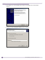
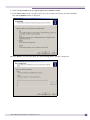
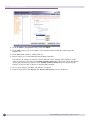
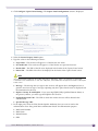
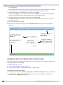
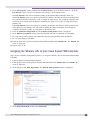
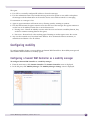
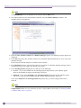
Accessing the Summit WM Controller for the first time
You can access the Summit WM Controller by using a laptop computer with a Web browser.
To access the Summit WM Controller using a web-enabled laptop:
1 Connect the Summit WM Controller’s management port to the web-enabled laptop computer with a
cross-over RJ 45 Ethernet cable.
NOTE
The IP address of the Summit WM Controller’s management port is 192.168.10.1.
2 Statically assign an unused IP address in the 192.168.10.0/24 subnet for the Ethernet port of the
laptop computer.
You can use any IP address from 192.168.10.2 to 192.168.10.254.
3 Launch your web browser.
Summit WM Getting Started Guide, Software Version 5.1
35
Summit WM Controller configuration
4 In the address bar, type https://192.168.10.1:5825. The Summit WM GUI login screen is
displayed.
5 In the User Name text box, type admin.
6 In the Password text box, type abc123.
7 Click Login. The Summit WM GUI is displayed.
NOTE
In the footer of the Summit WM GUI, the following is displayed:
• [host name | product name | up time]
• For example, [WM200/2000 | WM200/2000 | 01 days, 19:54]. If there is no key (unlicensed), UNLICENSED is
displayed besides the software version.
36
Summit WM Getting Started Guide, Software Version 5.1
• User is the user id you used to login in. For example, admin.
• Port Status is the connectivity state of the port. M is for the Management interface, which is on eth0 and the
numbered lights reflect the esa ports on the system. Green indicates the interface is active and running. Red
indicates the interface is down. In the Summit WM100 Controller, the footer of the Wireless Manager does not
include the link status of the physical interfaces.
8 From the main menu, click Summit Controller. The Summit Controller screen is displayed.
9 In the left pane, click IP Addresses. The factory default settings for the Summit WM Controller are
displayed.
NOTE
Only the following models support VLAN:
• Summit WM2000 Controller
Summit WM Getting Started Guide, Software Version 5.1
37
Summit WM Controller configuration
• Summit WM200 Controller
• Summit WM20 Controller
10 In the Management Port Settings section, click Modify. The System Port Configuration screen is
displayed.
11 Type the following information:
●
Hostname – Specifies the name of the Summit WM Controller by which it will be known. You
must assign a unique name for the Summit WM Controller.
●
Domain – Specifies the IP domain name of the enterprise network.
●
Management IP address – Specifies the new IP address for the Summit WM Controller’s
management port. Change the value in this text box to the IP address assigned to the Summit
WM Controller’s management port by your network administrator.
●
Subnet Mask – Specifies the subnet mask for the Summit WM Controller’s management port.
Change the value in this text box to the value provided by your network administrator.
●
Management Gateway – Specifies the default gateway of the network as provided by the
network administrator.
●
Primary DNS – Specifies the primary DNS server used by the network as provided by your
network administrator as provided by your network administrator. This field is optional.
●
Secondary DNS – Specifies the secondary DNS server used by the network as provided by your
network administrator. This field is optional.
12 Click OK.
NOTE
The Web connection between the computer and the Summit WM Controller is lost. The IP addresses are now set
to the network you defined.
Now you should connect the Summit WM Controller to the enterprise network. The following section
explains how to connect the Summit WM Controller to the enterprise network.
38
Summit WM Getting Started Guide, Software Version 5.1
Connecting the Summit WM Controller to the enterprise
network
To connect the Summit WM Controller to the enterprise network:
1 Disconnect your laptop computer from the Summit WM Controller management port.
2 Connect the Summit WM Controller management port to the enterprise Ethernet LAN. The Summit
WM Controller resets automatically.
3 Log on to the Summit WM GUI from any computer on the enterprise network. Type the following
URL in a browser to access the Summit WM GUI: https://<IP Address>:5825
Before you proceed further, you should change the default administrator password. The following
section explains how to change the default administrator password.
Changing the administrator password
To change the administrator password:
1 Login on the Summit WM Controller using the default administrator password.
2 From the main menu, click Summit Controller. The Summit Controller screen is displayed.
3 In the left, click Management Users.
4 In the user_admin table, click admin.
5 In the Modify User Password text box, type the new administrator password.
6 In the Modify User Confirm Password text-box, retype the new administrator password.
7 Click Change Password.
NOTE
Although the default password i.e., abc123, is of six characters in length, the new password must be of eight
characters in length. For more information, see the Summit WM User Guide.
Configuring the network time
The internal clocks of the Summit WM Controller and Wireless APs on a network may differ. You
should synchronize the clocks of the Summit WM Controller and the Wireless APs to ensure that the
logs bear correct time stamps on them. For more information on reports and logs, see Chapter 10
Working with reports and displays of Summit WM User Guide.
NOTE
The normal operation of the Summit WM Controller will not be affected if you do not synchronize the clock. The
clock synchronization is necessary to ensure that the logs bear the correct time stamps on them.
Summit WM Getting Started Guide, Software Version 5.1
39
Summit WM Controller configuration
The Summit WM Controller provides you the following two options to synchronize the clocks of
Summit WM Controller and the Wireless APs:
●
Using the system’s time – The system’s time is the Summit WM Controller’s time.
●
Using the network time protocol (NTP) – The Network Time Protocol is a protocol for synchronizing
the clocks of computer systems over packet-switched data networks.
Configuring the network time using the system’s time
To configure the network time, using the system’s time:
1 Login on the Summit WM Controller. The Summit WM GUI screen is displayed.
2 Click Summit Controller. The Summit Controller screen is displayed.
3 In the left pane, click Network Time. The Network Time screen is displayed.
4 From the Continent or Ocean drop-down list, click the appropriate large-scale geographic grouping
for the time zone.
5 From the Country drop-down list, click the appropriate country for the time zone. The contents of
the drop-down list change, based on the selection in the Continent or Ocean drop-down list.
6 From the Time Zone Region drop-down list, click the appropriate time zone region for the selected
country.
7 Click Apply Time Zone.
8 Select the Use System Time radio button.
You can modify the system’s date and time by changing the entries in the Use System Time text box.
The date is in mm-dd-yyyy format and the time is in hh:mm format.
9 Click Apply.
10 Reboot the Summit WM Controller. The WLAN network time is synchronized in accordance with the
Summit WM Controller’s time.
40
Summit WM Getting Started Guide, Software Version 5.1
Configuring the network time using the NTP
To configure the network time using the NTP:
1 Perform Step 1 to Step 7 of “Configuring the network time using the system’s time” on page 40.
2 Select Use NTP radio button.
3 In the Time Server 1 text box, type the IP address or FQDN (Full Qualified Domain Name) of a NTP
Time Server that is accessible on the enterprise network.
4 Repeat Step 3 for Time Server2 and Time Server3 text boxes.
If the system is not able to connect to the Time Server 1, it will attempt to connect to the additional
servers that have been specified in Time Server 2 and Time Server 3 text boxes.
5 Click Apply.
6 Reboot the Summit WM Controller. The WLAN network time is synchronized in accordance with the
specified time server.
Now you should apply a license key to the Summit WM Controller in order to enable its all the
functionalities.
Applying a license key
To apply the license:
1 Login on the Summit WM Controller.
2 From the main menu, click Summit Controller. The Summit Controller screen is displayed.
3 In the left pane, click Software Maintenance.
4 Click the SWM Product Keys tab.
5 In the Apply Product Key section, click Browse to navigate to the location of the software license
file, and select the file.
Summit WM Getting Started Guide, Software Version 5.1
41
Summit WM Controller configuration
6 Click Apply Now. The software license key is applied, and the Summit WM Controller reboots.
Now you should configure the Summit WM Controller’s physical ports. The following chapter
describes how to configure the Summit WM Controller’s physical ports.
42
Summit WM Getting Started Guide, Software Version 5.1
3
Physical ports configuration
This chapter describes how to configure the Summit WM Controller’s physical ports.
The topics in this chapter are organized as follows:
●
Physical data ports overview
●
Configuring physical data ports
Physical data ports overview
Port configuration defines the administrative state of each interface. By default, the data interface states
are disabled. You must enable each of the data interfaces individually. A disabled interface does not
allow data to flow (receive/transmit).
You can define the data ports to function as one of the following three types:
●
Host Port – You must use a Host Port definition to connect the Access Points with dynamic routing
disabled. The dynamic routing is disabled to ensure that the port does not participate in dynamic
routing operations to advertise the availability of WM Access Domain Services (WM-AD) hosted by
the WM. Host ports may still be used as the target for static route definitions.
●
Third-party AP Port – You must use a Third-party AP Port definition for a port to which you will be
connecting the third-party APs. The third-party APs must be deployed within a segregated network
for which the Summit WM Controller becomes the single point of access to the network. When you
define a port as the third-party AP port, the interface segregates the third-party AP from the
remaining network. Only one port can be configured for the third-party APs.
●
Router Port – You must use a Router Port definition for a port that you will be connecting to an
upstream, next-hop router in the network. When you define a port as the router port, the system
knows that the particular interface is eligible to participate in dynamic routing protocol exchanges.
The Summit WM Controller supports OSPF as the dynamic routing protocol.
The Summit WM Controller is shipped from the factory with all of its data ports set-up as host ports.
You must set-up or configure how each port should function.
If the interface is directly attached to an existing VLAN trunking port, you must specify which VLAN
the port belongs to by tagging the VLAN ID to the port. When you tag the VLAN ID to the port, all
packets associated with the port would be tagged with the corresponding VLAN. This enables the
Summit WM Controller to directly connect to a VLAN network without the need to remove VLAN tags
at the connection port.
NOTE
Only the following models support VLAN:
• Summit WM2000 Controller
• Summit WM2000 Controller
• Summit WM20 Controller
Summit WM Getting Started Guide, Software Version 5.1
43
Physical ports configuration
Configuring physical data ports
To configure the data port interfaces on the Summit WM Controller:
1 From the main menu, click Summit Controller. The Summit Controller screen is displayed.
2 In the left pane, click IP Addresses. The Management Port Settings screen is displayed.
The lower part of the screen displays the four ethernet ports, and each MAC address is displayed
under the MAC column.
NOTE
The number of ports displayed on the Management Port Settings screen (on the GUI) reflects the number of
physical ports the Summit WM Controller has. For example, Summit WM100/200/2000 Controllers have four
data ports, and hence the Management Port Settings screen will display four ports. The Summit WM1000
Controller has two data ports. Therefore the Management Port Settings screen will display two ports.
The lowest part of the screen displays the text boxes for IP address, MAC address, Subnet mask and
MTU. You can edit these values.
3 To enable the port, select the checkbox under the Enable column.
NOTE
You must disable all the interfaces that are not in use in order to avoid routing loops.
44
Summit WM Getting Started Guide, Software Version 5.1
4 Type the following:
●
IP address – The IP address of the physical ethernet port.
●
Subnet mask – The subnet mask for the IP address, which separates the network portion from
the host portion of the address (typically 255.255.255.0)
●
MTU – The maximum transmission unit or maximum packet size for this port. The default
setting is 1500. If you change this setting, and are using OSPF, you must make sure that the MTU
of each port in the OSPF link matches.
NOTE
The Summit WM Controller and Wireless AP are capable of participating in MTU discovery. During the MTU
discovery process, the Summit WM Controller and Wireless AP automatically learn the correct MTU, and then
correct their settings accordingly. If the routed connection to an Wireless AP travels a link that imposes a lower
MTU than the configured MTU, the Summit WM Controller and Wireless AP will correct their MTU settings
5 From the Function drop-down list, click one of the three functions.
●
Host Port – Specifies a port for connecting Wireless APs with no dynamic routing.
●
Third-party AP Port – Specifies a port to which the third-party AP is connected.
●
Router Port – Specifies a port that connects to an upstream, next-hop router in the network.
6 To enable management traffic on the port, select the Mgmt checkbox.
Enabling management provides access to the Summit WM Controller through the selected port using
SNMP (”get” only), SSH and HTTPS management services.
7 To enable the SLP protocol, select the SLP checkbox.
Selecting the SLP checkbox will enable the Summit WM Controller to advertise this port to the
network for Wireless APs’ discovery.
8 Select either of the two VLAN options:
●
Untagged: Select Untagged, if you are not using VLAN.
●
Tagged: Select Tagged, and specify the VLAN ID in the VLANID text box, if you are using
VLAN.
NOTE
The VLAN text boxes on the Management Port Settings screen are displayed only if you are using one of the
following models:
• Summit WM2000 Controller
• Summit WM200 Controller
• Summit WM20 Controller
9 To allow multicast support, click Enabled from the drop-down list.
When you enable the multicast support, the interface is used for relaying multicast traffic between
core and wireless devices. You must define only one port for the multicast traffic.
10 To save your changes, click Save.
11 Repeat Step 3 to Step 10 for every port that is to be enabled.
Now you should configure the routing on the Summit WM Controller. The following chapter describes
how to configure the Summit WM Controller’s physical ports.
Summit WM Getting Started Guide, Software Version 5.1
45
Physical ports configuration
46
Summit WM Getting Started Guide, Software Version 5.1
4
Routing Configuration
This chapter explains how to configure static routing and OSPF routing on the Summit WM Controller.
The topics in this chapter are organized as follows:
●
Configuring a static route
●
Configuring the OSPF routing
Configuring a static route
To configure a static route:
1 From the main menu, click Summit Controller. The Summit Controller screen is displayed.
2 In the left pane, click Routing Protocols. The Routing Protocols screen is displayed.
3 To add a new route, type the destination IP address of a packet in the Destination Address text box.
To define a default static route for any unknown address not in the routing table, type 0.0.0.0.
This is also called as defining the default gateway.
4 Type the appropriate subnet mask in the Subnet Mask text box to separate the network portion from
the host portion of the IP address (typically 255.255.255.0).
To define a default static route for any unknown address, type 0.0.0.0.
5 Type the IP address of the specific router port or gateway that serves as the next-hop for the packets
from Summit WM Controller gateway).
This router port (or gateway) must be on the same subnet as the Summit WM Controller.
6 Click Add. The new route is added to the list of routes.
Summit WM Getting Started Guide, Software Version 5.1
47
Routing Configuration
7 Select the Override dynamic routes check box to give priority over the OSPF routes that the Summit
WM Controller uses for routing.
By default, the Override dynamic routes is enabled. If you want to remove priority for static routes
so that the routing is always controlled dynamically, clear the Override dynamic routes check box.
8 To save your changes, click Save.
Viewing the forwarding table
You can view the defined routes, whether static or OSPF, and their current status in the forwarding
table.
To view the forwarding table:
1 From the main menu, click Reports. The Reports & Displays screen is displayed.
2 Click Forwarding Table. The Forwarding Table is displayed.
3 To update the display, click Refresh.
Configuring the OSPF routing
To configure the OSPF routing, you must:
48
●
Define one data port as a router port on the IP addresses screen.
●
Enable OSPF globally on the Summit WM Controller. For more information, see “Enabling OSPF
globally on the Summit WM Controller” on page 49.
Summit WM Getting Started Guide, Software Version 5.1
●
Define the global OSPF parameters. For more information, see “Defining the global OSPF
parameters” on page 50.
Ensure that the OSPF parameters defined for the Summit WM Controller are consistent with the
adjacent routers in the OSPF area. The consistency includes the following:
●
Timer Settings – If the peer router has different timer settings, the protocol timer settings in the
Summit WM Controller must be changed to the peer router to match in order to achieve OSPF
adjacency.
●
MTU – The MTU of the ports on either sides of the OSPF link must match. You must remember
here that the MTU for ports is set to 1500 on the Summit WM Controller is when configuring the
physical data ports on IP addresses’ screen. The value of 1500 matches the MTU in standard
routers.
Enabling OSPF globally on the Summit WM Controller
To enable the OSPF globally on the Summit WM Controller:
1 From the main menu, click Summit Controller. The Summit Controller screen is displayed.
2 In the left pane, click Routing Protocols. The Routing Protocols screen is displayed.
3 Click the OSPF tab.
4 From the OSPF Status drop-down list, click ON to enable OSPF.
5 In the Router ID text box, type the IP address of the Summit WM Controller.
The router ID must be unique across the OSPF area.
If the Router ID text box is left blank, the IP address of one of the Summit WM Controller’s will be
picked as the router ID.
6 In the Area ID text box, type the area.
The main area in OSPF depends upon your network configuration. You must find out the main area
from your network administrator.
Summit WM Getting Started Guide, Software Version 5.1
49
Routing Configuration
7 In the Area Type drop-down list, click one of the following:
●
Default – Acts as the backbone area (also known as area zero). It forms the core of an OSPF
network. All other areas are connected to it, and inter-area routing occurs via a router connected
to the backbone area.
●
Stub – Does not receive external routes. External routes are defined as routes, which are
distributed in OSPF via another routing protocol. Therefore, the Stub area relies on a default route
to send traffic routes outside the present domain.
●
Not-so-stubby – A type of stub area that can import autonomous system (AS) external routes and
send them to the default/backbone area, but can not receive AS external routes from the
backbone or other areas.
8 To save your changes, click Save.
Defining the global OSPF parameters
To define the global OSPF parameters:
1 From the main menu, click Summit Controller. The Summit Controller screen is displayed.
2 In the left pane, click Routing Protocols. The Routing Protocols screen is displayed.
3 Click the OSPF tab.
4 From the Port Status drop-down list, click Enabled. The OSPF is enabled on the port.
NOTE
Only the interfaces defined as router type are available for OSPF neighborhood establishment.
5 In the Link Cost text box, type the OSPF standard for your network for this port.
The Link Cost is the cost of sending a data packet on the interface. The lower the cost, the more
likely the interface will be used to forward the data traffic.
NOTE
If more than one port is enabled for OSPF, you must prevent the Summit WM Controller from serving as a router
for the other traffic. In order to do this, you must set the Link Cost to its maximum value of 65535.
6 From the Authentication drop-down list, click the authentication type of OSPF on your network:
●
None: The default is None. If None is selected, leave the Password text box blank.
●
Password: If Password is selected, type the password in the Password text box in the.
7 Type the values in the following text boxes.
●
Hello-Interval – Specifies the time in seconds (displays OSPF default). The default setting is 10.
●
Dead-Interval – Specifies the time in seconds (displays OSPF default). The default setting is 40.
●
Retransmit-Interval – Specifies the time in seconds (displays OSPF default). The default setting is
5.
●
Transmit Delay – Specifies the time in seconds (displays OSPF default). The default setting is 1.
8 To save your changes, click Save.
Now you must confirm that the ports are set for OSPF.
50
Summit WM Getting Started Guide, Software Version 5.1
Confirming the ports are set for OSPF
To confirm the ports are set for OSPF:
1 From the main menu, click Summit Controller. The Summit Controller screen is displayed.
2 On the Routing Protocols screen, click View Forwarding Table. The Forwarding Table is displayed.
3 Click the OSPF Neighbor tab.
If OSPF protocol is enabled, this report displays the current neighbors for OSPF.
4 Click the OSPF Linkstate tab.
If OSPF protocol is enabled, the report displays the link state advertisement (LSAs) received by the
running OSPF protocol.
5 To update the screen, click Refresh.
Now you should configure the DHCP, DNS and RADIUS servers on the network.
The following chapter explains how to configure DHCP, DNS and IAS services on Windows 2003
Server.
Summit WM Getting Started Guide, Software Version 5.1
51
Routing Configuration
52
Summit WM Getting Started Guide, Software Version 5.1
5
Configuring DHCP, DNS and IAS services
This chapter describes how to configure DHCP, DNS and IAS services on Windows 2003 Server. In
addition, the chapter explains how to configure DHCP service on a Linux-based server.
Note that your Windows 2003 or Linux server may have a different configuration process than what is
described here. You must refer to your manufacturer’s document to know the configuration process that
is specific to your server.
The configuration processes described in this chapter should be used as examples.
The topics in this chapter are organized as follows:
●
DHCP service configuration
●
IAS service configuration
●
DNS service configuration
DHCP service configuration
Before you can configure the DHCP service, you must install it on the server. DHCP is not installed by
default during a typical installation of Windows Standard Server 2003 or Windows Enterprise Server
2003. You can install DHCP either during the initial installation of Windows Server 2003 or after the
initial installation is completed.
You may also include 078 SLP DA Option. The 078 SLP DA Option is not included by default during a
typical installation of DHCP service.
You may visit http://support.microsoft.com to learn how to install DHCP and 078 SLP DA Option on
Windows 2003.
The following section describes how to configure DHCP for Summit WM Wireless LAN (WLAN)
Solution.
Configuring DHCP in Windows 2003 Server
You must also enable 078 SLP DA Option for every scope you define. A scope is a collection of IP
addresses meant to be distributed by the DHCP server to the client devices on a subnet.
The SLP DA is used by:
●
The Wireless APs to discover the Summit WM Controller.
●
The mobility agents to discover the mobility manager.
To configure DHCP in Window 2003 Server:
1 Click Start, point to Administrative Tool, and then click DHCP.
2 In the console tree, right-click the DHCP server on which you want to create the new DHCP scope,
and then click New Scope.
Summit WM Getting Started Guide, Software Version 5.1
53
Configuring DHCP, DNS and IAS services
3 Click Next. The Scope Name window is displayed.
4 In the Name and Description text boxes, type the scope’s name and the description respectively.
This can be any name that you want, but it should be descriptive enough so that you can identify
the purpose of the scope on your network.
5 Click Next. The IP Address Range window is displayed.
6 In the Start IP address and the End IP address text boxes, type the start and end of the IP addresses’
range that you want to be distributed to the network.
Range – Is the range of addresses that the scope will distribute across the network. You must use the
range provided by your network administrator.
7 In the Length text box, type the numeric value of the subnet mask’s bits; or in the Subnet mask text
box, type the subnet mask’s IP address.
A subnet mask defines how many bits of an IP address to use for the network/subnet IDs and how
many bits to use for the host ID. You can specify the subnet mask by length or as an IP address. You
must use the Length (or the Subnet mask) provided by your network administrator.
8 Click Next. The Add Exclusions window is displayed.
9 In the Start IP address and the End IP address text boxes, type the start and end of the IP addresses’
range that you want to exclude from the distribution.
You must use the exclusion range provided by your network administrator.
10 Click Next. The Lease Duration window is displayed.
The DHCP server assigns a client an IP address for a given amount of time. The amount of time for
which the IP address can be leased is defined in the Lease Duration window.
11 In the Days, Hours and Minutes text box, type the lease duration.
You must use the Lease Duration as specified by your network administrator.
12 Click Next. The Configure DHCP Options window is displayed.
13 Select Yes, I want to configure these options now, and then click Next. The Router (Default
Gateway) window is displayed.
54
Summit WM Getting Started Guide, Software Version 5.1
14 In the IP address text box, type the network’s default gateway.
You must use the default gateway provided by your network administrator.
15 Click Next. The Domain Name and DNS Servers window is displayed.
16 In the Parent domain text box, type your company’s domain name.
You must use the Parent Domain provided by your network administrator.
17 In the Server name text box, type your server name.
You must use the Server name provided by your network administrator.
18 In the IP address text box, type your server’s IP address, and click Add.
19 Click Next. The WINS Servers window is displayed.
20 Click Next. The Activate Scope window is displayed.
Summit WM Getting Started Guide, Software Version 5.1
55
Configuring DHCP, DNS and IAS services
21 Select Yes, I want to activate this scope now, and click Next. The wizard displays the following
message: This server is now a DHCP server.
22 Click Start, point to Administrative Tool, and then click DHCP. The DHCP console tree is displayed.
23 Select the scope you configured, and right-click.
24 Select Configure Options. The Server Options window is displayed.
25 Enable 078 SLP DA.
26 In the lower pane of the screen, type the dotted decimal values of the SLP DA’s IP address.
NOTE
• The Wireless APs use the SLP DA to discover the Summit WM Controller.
• The mobility agents use the SLP DA to discover the mobility manager.
NOTE
If there is no SLP deployment on the enterprise network, the Summit WM Controller is configured to act as a DA
by default. If you put the Summit WM Controller’s IP address(es) in a DHCP server for Option 78, Wireless APs
will interact with the Summit WM Controller for discovery.
Similarly, the mobility agents will also interact with the Summit WM Controller to discover the mobility manager.
27 Click Apply, and then click OK.
Configuring DHCP in Red Hat Linux Server
You can configure a DHCP server using the configuration file /etc/dhcpd.conf.
DHCP also uses the file /var/lib/dhcp/dhcpd.leases to store the client lease database.
The first step in configuring a DHCP server is to create the configuration file that stores the network
information for the clients. Global options can be declared for all clients, or options can be declared for
each client system.
The configuration file can contain any extra tabs or blank lines for easier formatting. The keywords are
not case-sensitive and lines beginning with a hash mark (#) are considered comments.
To use the recommended mode, add the following line to the top of the configuration file:
ddns-update-style interim;
Read the dhcpd.conf man page for details about the different modes.
There are two types of statements in the configuration file:
●
Parameters – State how to perform a task, whether to perform a task or what networking
configuration options to use to send to the client.
●
Declarations – Describe the topology of the network, describe the clients, provide addresses for the
clients, or apply a group of parameters to a group of declarations.
Some parameters must start with the option keyword and are referred to as options. Options configure
DHCP options; whereas, parameters configure values that are not optional or control how the DHCP
server behaves.
56
Summit WM Getting Started Guide, Software Version 5.1
Parameters (including options) declared before a section enclosed in curly brackets {} are considered
global parameters. Global parameters apply to all the sections below it.
NOTE
If you change the configuration file, the changes will not take effect until you restart the DHCP daemon with the
command service dhcpd restart.
The following is the example of DHCP configuration on a Red Hat Linux Server.
For Wireless AP subnet
subnet 10.209.0.0 netmask 255.255.255.0 {
option routers 10.209.0.2; ### This is the network’s default gateway address.
option subnet-mask 255.255.255.0
option domain-name xyznetworks.ca
option domain-name servers 192.168.1.3, 207.236, 176.11
range 10.209.0.3 10.209.0.40;
default-lease-time 7200000 ###The figures are in seconds.
option slp-directory-agent true 10.209.0.1, 10.209.0.3; ####The Wireless APs
use the SLP DA to discover the Summit WM Controller, and the mobility agents
use it to discover the mobility manager.
authoritative;
}
For WM-AD subnets (In Summit WM Controller it is configured as Use DHCP Relay)
if you are utilizing multiple WM-ADs you must configure the Red Hat Linux server for every WM-AD.
The following is the example of DHCP configuration in Red Hat Linux for two WM-ADs (For more
information, see Chapter 7, “WM-AD configuration”).
subnet 172.29.31.0 netmask 255.255.255.224
option routers 172.29.31.1; #### This is the WM-AD 1 gateway.
option subnet-mask 255. 255. 255.0
option domain-name toronto.xyznetworks.com”;
option domain-name-servers 192.1.1.3;
range 172.29.31.2 172.29.31.30;
default-lease-time 36000;
max-lease-time 7200000;###The figures are in seconds.
authoritative;
}
Summit WM Getting Started Guide, Software Version 5.1
57
Configuring DHCP, DNS and IAS services
subnet 172.29.2.0 netmask 255.255.255.224
option routers 172.29.2.1; #### This is the WM-AD 2 gateway.
option subnet-mask 255. 255. 255.0
option domain-name toronto.xyznetworks.com”;
option domain-name-servers 192.1.1.3;
range 172.29.2.2 172.29.2.30;
default-lease-time 36000;
max-lease-time 7200000;###The figures are in seconds.
authoritative;
}
IAS service configuration
Microsoft Internet Authentication Service (IAS) can run as a Remote Authentication Dial-in User Service
(RADIUS) server. You can use IAS for centralized authentication and accounting of multiple client
devices.
IAS configuration involves the following steps:
●
Step 1 – Installing IAS on Windows 2003 Server
●
Step 2 – Enabling IAS to authenticate users in active directory
●
Step 3 – Configuring IAS properties
●
Step 4 – Configuring Summit WM Controller as IAS client
●
Step 5– Configuring Remote Access Policies
Installing IAS on Windows 2003 Server
You must install IAS on Windows 2003 Server according to the documentation provided with the server.
You may also visit http://support.microsoft.com to learn how to install IAS on Windows 2003.
Enabling IAS to authenticate users in active directory
To enable IAS to authenticate users in active directory:
1 Click Start, point to Programs, point to Administrative Tools, and then click Internet
Authentication Service.
2 In the Action menu, click Register Service in Active Directory.
3 To confirm the IAS registration in the local domain, click OK.
58
Summit WM Getting Started Guide, Software Version 5.1
Configuring IAS properties
To configure the IAS properties:
1 Click Start, point to Programs, point to Administrative Tools, and then click Internet
Authentication Service.
2 Right-click Internet Authentication Service (Local), and then click Properties.
3 In the Description text box, type a name that you want to assign to this IAS server.
4 If you do not want to record the rejected authentication requests, clear the Log rejected or discarded
authentication requests checkbox.
NOTE
You can use the log file to determine if unauthorized users are attempting to authenticate themselves in the
domain.
5 If you do not want to record the successful authentication requests, clear the Log successful
authentication requests checkbox.
NOTE
You can use the log file to determine the usage patterns of wireless users.
6 Click the Ports tab.
7 In the Authentication text box, type the Summit WM Controller’s port # that is used to access the
authentication (IAS) service.
8 In the Accounting text box, type the Summit WM Controller’s port # that is used to access the
accounting service.
Summit WM Getting Started Guide, Software Version 5.1
59
Configuring DHCP, DNS and IAS services
You must note that the values you type in the Authentication text box should match the value that
you define in the Port text box of Auth section on the Auth & Acct tab of Summit WM Controller’s
WM-AD screen. For more information, see “Configuring authentication mechanism for WM-AD” on
page 97 of Chapter 7, “WM-AD configuration.”
Similarly, the values you type in the Accounting text box, should match the value that you define in
the Port text box of Acct section in the Acc & Acct tab of Summit WM Controller’s WM-AD
screen.For more information, see “Configuring authentication mechanism for WM-AD” on page 97
of Chapter 7, “WM-AD configuration.”
60
Summit WM Getting Started Guide, Software Version 5.1
Configuring Summit WM Controller as IAS client
To configure Summit WM Controller as IAS client:
1 Click Start, point to Administrative Tool, and then click Internet Authentication Service.
2 Right-click Clients, and then New Client.
3 In the Friendly name text box, type the name that you want to assign to the Summit WM Controller,
and then click Next.
4 In the Client address (IP or DNS) text box, type the IP address of the Summit WM Controller, and
then click Verify.
5 Click Resolve. If the IP address is correct, it appears in the Search results text box.
6 Click Use this IP.
7 In the Client-Vendor list, click RADIUS Standard.
8 In the Shared secret text box, type a password that both the IAS server and the Summit WM
Controller will use to mutually authenticate.
NOTE
This password is case-sensitive. You can use alphanumeric characters. You must configure the same shared
secret password for WM-AD Global Settings. For more information, see Section 6.8 WM-AD Global Settings of
Summit WM User Guide.
9 Retype the password in the Confirm shared secret box, and then click Finish.
Configuring Remote Access Policies
To configure Remote Access Policy:
1 Click Start, point to Administrative Tool, and then click Internet Authentication Service.
2 Click Remote Access Policies.
3 In the right pane of the Internet Authentication Service, click Allow access if dial-in permission is
enabled, and then right-click Allow access if dial-in permission is enabled.
4 Click Delete. A dialogue box is displayed.
5 Click Yes on the dialogue box.
Summit WM Getting Started Guide, Software Version 5.1
61
Configuring DHCP, DNS and IAS services
6 On the Action menu, click New Remote Access Policy. The New Remote Access Policy Wizard is
displayed.
7 Click Next. The Policy Configuration Method window is displayed.
62
Summit WM Getting Started Guide, Software Version 5.1
8 Select Use the wizard to set up a typical policy for a common scenario.
9 In the Policy name text box, type the name you want to assign to the policy, and then click Next.
The Access Method window is displayed.
10 Select Wireless and then click Next. The User or Group Access window is displayed.
Summit WM Getting Started Guide, Software Version 5.1
63
Configuring DHCP, DNS and IAS services
11 Select User or Group, and click Next. The Authentication Methods window is displayed.
12 Select Protected EAP (PEAP) or Smart card or other certificate, and click Next.
13 Click Finish. The new policy is displayed in the right pane.
14 In the right pane, select and right-click the newly configured remote access policy.
15 Select Properties. The Properties window is displayed.
16 Select Grant Remote Access Permission.
17 Click Apply and then click OK.
18 Click Add. The Attributes window is displayed.
19 Select IP address. The Client IP-Address window is displayed.
20 In the Client IP-Address window, type the Summit WM Controller’s IP address.
21 Click OK.
DNS service configuration
The domain name system (DNS) stores and associates many types of information with domain names,
but most importantly, it translates domain names (computer hostnames) to IP addresses.
You must install DNS on Windows 2003 Server according to the documents provided with the server.
Visit http://support.microsoft.com to learn how to install DNS on Windows 2003.
The DNS configuration involves two steps:
64
●
Step 1 – Configuring the DNS for internet access
●
Step 2 – Configuring DNS for Wireless APs discovery.
Summit WM Getting Started Guide, Software Version 5.1
Configuring DNS for internet access
To configure DNS for internet access:
1 Click Start, point to All Programs, point to Administrative Tools, and then click Configure Your
Server Wizard.
2 Click Next. The Summary of Selections window is displayed.
NOTE
The Summary of Selections window should list the following two items: Install DNS and Run the Configure a DNS
Wizard to configure DNS.
If the Summary of Selections window does not list these two items, you must:
• Click Back to return to DNS Server Roles window.
• Click DNS.
• Click Next.
3 In the Summary of Selections window, click Next. The Select Configuration Action window is
displayed.
When the Configure Your Server wizard installs the DNS service, it first determines whether the IP
address for this server is static or the server is configured to secure it automatically.
If your server is currently configured to obtain its IP address, the wizard prompts you to configure
the server with a static IP address instead of displaying the Select Configuration Action window.
To configure the server with a static IP address:
a In the Local Area Connection Properties, click Internet Protocol (TCP/IP), and then click
Properties. The Internet Protocol (TCP/IP) Properties window is displayed.
b In the Internet Protocol (TCP/IP) Properties window, click Use the following IP address.
c
In the Static IP address, Subnet mask, and the Default gateway text boxes, type the static IP
address, the subnet mask and the IP address of the default gateway respectively.
d In the Preferred DNS text box, type the IP address of the server.
e In the Alternate DNS text box, type the IP address of another internal DNS server.
The Alternate DNS text box is optional.
a Click OK, and then click Close.
4 In the Select Configuration Action window, select the Create a forward lookup zone checkbox, and
then click Next. The Primary Server Location window is displayed.
5 In the Primary Server Location window, select This server maintains the zone, and then click Next.
The Zone name window is displayed.
6 In the Zone name text box, type the name of the DNS zone for your network, and then click Next.
The Dynamic Update window is displayed.
The zone name is identical to the DNS domain for small organization or branch office.
7 In the Dynamic Update window, click Allow both nonsecure and secure dynamic updates, and
then click Next. The Forwarders window is displayed.
8 In the Forwarders window, click Yes, it should forward queries to DNS servers with the following
IP addresses.
When you select this feature, all DNS queries for DNS names are forwarded to a DNS at either your
ISP or central office.
9 In the IP addresses text box, type one or more IP addresses that either your ISP or central office DNS
servers use, and click Next.
Summit WM Getting Started Guide, Software Version 5.1
65
Configuring DHCP, DNS and IAS services
10 Click Finish. The wizard displays the following message: This server is Now a DNS Server.
Configuring DNS for Wireless APs discovery
To configure DNS for Wireless APs discovery:
1 Click Start, point to All Programs, point to Administrative Tools, and then click DNS.
2 Select the domain.
3 In the Action menu, select New Domain. The New DNS Domain window is displayed.
4 In the New DNS Domain window, type the name for the new domain.
5 Restart the service. The new domain is displayed as the child domain.
6 Right-click the new domain name, and select New Host. The New Host window is displayed.
7 In the Name text box, type the Summit WM Controller’s name.
8 In the IP address text box, type the Summit WM Controller’s IP address.
9 Select Create associated pointer (PTR) record checkbox.
10 Click Add Host. The new host is displayed in the right pane of the screen.
11 Quit DNS.
Now you must configure the Wireless APs via the Summit WM Controller.
66
Summit WM Getting Started Guide, Software Version 5.1
6
Wireless AP configuration
This chapter describes how to configure and manage the Wireless APs.
The topics in this chapter are organized as follows:
●
Wireless AP overview
●
Configuring the Wireless APs for the first time
●
Assigning names to Wireless APs
●
Modifying Wireless APs’ properties
●
Configuring static IP address for Wireless APs
●
Configuring VLAN tags for Wireless APs
●
Wireless AP’s LED states
Wireless AP overview
Wireless APs are enterprise-class access points that deliver secure wireless access via the layer 3 tunnel
for enterprise deployments. They provide advanced RF capabilities, security, reliability and scalability.
The Wireless APs provide an unmatched level of flexibility and performance for complex, time-sensitive
functions including QoS, encryption and rogue AP detection.
The Wireless APs, by default, do not have a graphical user interface (GUI); they are configured and
managed by the Summit WM GUI. In addition, you can centrally manage (verify and upgrade) the
Wireless AP firmware image via the Summit WM GUI.
All communication between the Summit WM Controller and the Wireless AP is carried out using a
UDP-based protocol. The IP traffic, coming from the Wireless AP is encapsulated, and is directed to the
Summit WM Controller. The Summit WM Controller decapsulates the packets and routes them to the
appropriate destinations while managing sessions and applying policy.
The Wireless AP comes in the following three variants:
●
Altitude AP
●
Outdoor AP (Siemens brand of outdoor AP)
●
Altitude 802.11n AP
NOTE
The term, ‘Wireless AP’, is used in this document to encompass all the three variants — Altitude AP and Outdoor
AP (Siemens) and Altitude 802.11n AP. The variants are identified specifically at only those places where it is
necessary to do so.
Summit WM Getting Started Guide, Software Version 5.1
67
Wireless AP configuration
NOTE
The configuration process is same for all three variants — Altitude AP, Outdoor AP, and Altitude 802.11n AP — and
is done via the Summit WM Controller.
Altitude AP
The Altitude AP is meant for indoor environments. It can be mounted on walls or ceilings, using special
brackets, and can be kept completely out of sight.
The Altitude AP is available in the following two models:
●
Altitude 350-2i – Internal antenna, internal dual (multimode) diversity antennas
●
Altitude 350-2d – External antenna (dual external antennas), RP-SMA connectors
NOTE
Since the Altitude AP is meant for indoor environments, it is also referred to as Indoor AP.
Outdoor AP
The Outdoor AP enables you to extend your Wireless LAN beyond the confines of indoor locations.
They are resistant to harsh outdoor conditions and extreme temperatures. Using the advanced wireless
distribution feature of Summit WM Wireless LAN, the Outdoor AP can extend your Wireless LAN to
outdoor locations without Ethernet cabling. A mounting bracket is available to enable quick and easy
mounting of the Outdoor APs to walls, rails and poles.
NOTE
Although the Outdoor AP is meant for outdoor environments, it can also be deployed in indoor environments.
The Outdoor AP supports the 802.11a, 802.11g and full backward compatibility with legacy 802.11b
devices.
NOTE
Since the Outdoor AP is meant for outdoor environments, it is also referred to as Outdoor AP.
Altitude 802.11n AP
The Altitude 802.11n AP is an IEEE 802.11n (draft)-compliant access point that offers significant increase
in data throughput and coverage range without additional bandwidth or transmit power. With both 2.4
GHz and 5 GHz 802.11n (draft) standard radio modules, the 802.11n AP delivers total data rates of up
to 300 Mbps. Given that the improved throughput of 300 Mbps will be spread over a number of
simultaneous users, the performance of 802.11n AP will be close to that of a wired 100 Mbps Ethernet
connection — the standard for desktop connectivity. With the 802.11n AP, the mobile users get the
68
Summit WM Getting Started Guide, Software Version 5.1
experience similar to wired networks while accessing high-bandwidth data, voice, and video
applications.
The Altitude 802.11n AP is available in the following two models:
●
Altitude 450 – 3 internal antennas
●
Altitude 451 – 3 internal antennas, RP-SMA connectors
MIMO
The pivot of 802.11 AP is MIMO (multiple input, multiple output) — a technology that uses advanced
signal processing with multiple antennas to improve the throughput. MIMO takes the advantage of
multipath propagation to decrease packet retries to improve the fidelity of the wireless network.
The 802.11n AP’s MIMO radio sends out three radio signals at the same time through its three radio
transceivers. Each of these signals is called a spatial stream. Each spatial stream is sent out from its own
transceiver, using its own antenna. Because the location of the antennas on the 802.11n AP is spaced out,
each spatial stream follows a slightly different path to the client devices. Furthermore, the three spatial
streams get multiplied into several streams as they bounce off the obstructions in the vicinity. This
phenomenon is called multipath. Since these streams are bounced from different surfaces, they follow
different paths to the client device. The client device, which is also 802.11n compliant, too has multiple
antennas. Each of the antennas independently decodes the arriving signal. Then each antenna’s decoded
signal is combined with the decoded signals from the other antennas. After a complex calculation via
the software algorithm, the result is much better signal and increased throughput.
Summit WM Getting Started Guide, Software Version 5.1
69
Wireless AP configuration
Figure 15: MIMO in Altitude 802.11n AP
The installation of 802.11n APs is also made easy – the 802.11n APs do not need to be deployed in the
client device’s “line of sight”. On the contrary, the 802.11n APs work better when radio signals bounce
off the obstructions that are typical of any indoor wireless LAN environment — cube walls, doors,
partitions etc. — to reach the client device. Greater the number of bounces, more the number of streams
reaching the client device, and better the phenomenon of multipath.
NOTE
MIMO should not be confused with Diversity feature. While the Diversity is the use of two antennas to increase the
odds that a better radio stream is received on either of the antennas, MIMO antennas radiate and receive multistreams of the same packet to achieve the increased throughput.
The Diversity feature is meant to beat the liability of RF corruption, arising out of multipath, whereas MIMO converts
the liability of multipath to its advantage.
MIMO also enhances ‘radio receive sensitivity’, and improves noise rejection.
Channel bonding
In addition to MIMO technology, 802.11n AP makes a number of additional changes to the radio to
increase the effective throughput of the Wireless LAN. The radios of regular Altitude APs use radio
channel spacings that are 20 MHz wide. The radios of 802.11n AP use two channels at the same time
i.e., 40 MHz wide. By using the two 20 MHz channel in this way, 802.11n AP achieves double
70
Summit WM Getting Started Guide, Software Version 5.1
throughput. The 40-MHz channels in 802.11n are two adjacent 20-MHz channels, bonded together. This
technique of using two channels at the same time is called channel bonding.
Shortened guard interval
The purpose of the guard interval is to introduce immunity to propagation delays, echoes and
reflections of symbols in orthogonal frequency division multiplexing (OFDM) — a method by which
information is transmitted via a radio signal in Wireless APs.
In OFDM method, the beginning of each symbol is preceded by a guard interval. As long as the echoes
falls within this interval, they will not affect the safe decoding of the actual data, as data is only
interpreted outside the guard interval. Longer guard periods reduce the channel efficiency. The 802.11n
AP provides reduced guard periods, thereby increasing the throughput.
MAC enhancements
The 802.11n AP also has improved MAC layer protocol that reduces the overheads (in the MAC layer
protocol) and the contention losses. This again results in increased throughput.
NOTE
The Altitude 802.11n AP is backward-compatible with existing 802.11a/b/g networks.
NOTE
The Altitude 802.11n AP cannot operate as a stand-alone access point.
The 802.11n AP is available in the following two models:
●
Altitude 450 – Three internal antennas
●
Altitude 451 – Three external antennas
NOTE
The 802.11n AP cannot be deployed in an outdoor environment.
Wireless AP’s default IP address and first-time configuration
Wireless APs are shipped from the factory with a default IP address — 192.168.1.20. The default IP
address simplifies the first-time IP address configuration process for Wireless APs. The Wireless AP
returns to its default IP address if it is not successful in its discovery process.
The Wireless APs can have their IP addresses assigned using either of the following two methods — a
Dynamic Host Configuration Protocol (DHCP) server assigns the IP address, or an administrator assigns
the IP address using the static configuration option. The DCHP IP address assignment method is the
Summit WM Getting Started Guide, Software Version 5.1
71
Wireless AP configuration
default method for Wireless AP configuration. The Wireless AP default IP address impacts the first-time
configuration processes for both methods:
●
DHCP server – If successful, the Wireless AP is assigned an IP address by the network’s DHCP
server when the Wireless AP is powered on.
●
If the DHCP assignment is not successful in the first 60 seconds, the Wireless AP returns to its
default IP address.
●
The Wireless AP waits for 30 seconds in default IP address mode before attempting again to
acquire the IP address from the DHCP.
●
The process repeats itself until the DHCP assignment is successful, or until an administrator
assigns the Wireless AP an IP address using static configuration.
NOTE
You can telnet the Wireless AP during the 30 seconds the Wireless AP is assigned its default IP address. If a
static IP address is assigned during this period, you must reboot the Wireless AP for the configuration to take
effect.
●
Static configuration – Power up the Wireless AP, connect it to a laptop, and then ping its default IP
address.
●
If the ping is successful, telnet the Wireless AP within 30 seconds and configure the static IP
address.
If the Wireless AP is not configured within the 30 seconds, it again attempts to get the IP address via
the DHCP assignment.
NOTE
For more information on how to telnet the Wireless AP, see the Summit WM CLI Reference Guide.
NOTE
For more information on Wireless APs default IP address, see the Summit WM User Guide.
Configuring the Wireless APs for the first time
Before you start configuring the Wireless APs, ensure that you have:
●
Set-up, installed and configured the Summit WM Controller.
●
Installed the Wireless APs at the location indicated by your site survey.
NOTE
• If you are installing the Altitude AP, see the Altitude 350-2i/350-2d AP Installation Guide.
• If you are installing the Outdoor AP, see the Outdoor AP Installation Guide.
• If you are installing the Altitude 802.11n AP, see the Altitude 802.11n AP Installation Guide.
●
72
To configure the Wireless APs for the first time:
Summit WM Getting Started Guide, Software Version 5.1
1 From the main menu, click Altitude APs. The Altitude AP screen is displayed.
2 In the left pane, click WAP Registration.
3 In the Security Mode section, select one of the following options:
NOTE
Security mode is a Summit WM Controller property. It defines how the Summit WM Controller behaves when
registering new devices. During the registration process, the Summit WM Controller’s approval of the Wireless
APs depends on the security mode that has been set.
●
●
Allow all APs to connect:
■
If the Summit WM Controller does not recognize the registering serial number, a new
registration record is automatically created for the Wireless AP. The Wireless AP receives a
default configuration.
■
If the Summit WM Controller recognizes the serial number, it indicates that the registering
device is pre-registered with the Summit WM Controller. The Summit WM Controller uses the
existing registration record, and existing configuration record to authenticate and configure
the Wireless AP respectively.
Allow only approved Wireless APs to connect:
■
If the Summit WM Controller does not recognize the Wireless AP, the Wireless AP’s
registration record is created in pending state. You must manually approve a pending Wireless
AP. As long as the Wireless AP is in pending state, it receives minimum configuration that
only allows it to maintain an active link with the Summit WM Controller for future state
change. For more information, see “Manually approving pending Wireless APs” on page 74.
■
If the Summit WM Controller recognizes the serial number, it uses the existing registration
record to authenticate the Wireless AP. Following the successful authentication, the Wireless
AP is configured according to its stored configuration record.
Summit WM Getting Started Guide, Software Version 5.1
73
Wireless AP configuration
4 In the Discovery Timers section, type the discovery timer values in the following text boxes:
●
Number of retries – Limited to 255 in a five minute discovery period. The default value is 3.
●
Default between retries – The default value is 1 second.
5 To save your changes, click Save.
6 To initiate the discovery and registration process, connect the Wireless AP to a power source.
The Wireless APs can be connected and powered in several ways. For more information, see the
following section.
Powering the Wireless APs
Altitude AP
The Altitude AP can be connected, and powered in the following ways:
●
●
Power over Ethernet (802.3af):
●
PoE enabled switch port
●
PoE Injector
Power by AC adaptor
Outdoor AP
The Outdoor AP can be connected, and powered in the following ways:
●
Power over Ethernet
●
PoE enabled switch port
●
PoE Injector
●
Power by 48 V direct voltage
●
110-230 V DC direct voltage
For more information, see the Outdoor AP Installation Guide.
Altitude 802.11n AP
The Altitude 802.11n can be connected, and powered in the following ways:
●
●
Power over Ethernet
●
PoE enabled switch port
●
PoE Injector
Power by 48 V direct voltage
Manually approving pending Wireless APs
If the Summit WM Controller does not recognize the Wireless AP, the Wireless AP’s registration record
is created in pending state. You must manually approve a pending Wireless AP. As long as the Wireless
74
Summit WM Getting Started Guide, Software Version 5.1
AP is in the pending state, it receives minimum configuration that only allows it to maintain an active
link with the Summit WM Controller for future state change.
To manually approve pending Wireless APs:
1 From the main menu, click Altitude APs. The Altitude AP screen is displayed
2 In the left pane, click Access Approval. The Access Approval screen is displayed.
3 In the Select Altitude APs section, click Pending. The pending Wireless APs are selected.
4 In the Perform action on selected Wireless APs, click Approved. The state of the selected Wireless
APs is changed from “Pending” to “Approved”.
Assigning names to Wireless APs
After the Wireless APs are successfully registered, you can assign them appropriate names.
To assign a name to a Wireless AP:
1 From the main menu, click Altitude APs. The Altitude AP screen is displayed.
2 In the Altitude APs list, click the Wireless AP for which you want to assign a name. The AP
Properties tab is displayed.
3 In the Name text box, type the name that you want to assign to the selected Wireless AP.
4 To save your changes, click Save.
NOTE
You can modify the Wireless AP’s properties that are displayed in the right pane of the Altitude AP screen. For more
information, see “Modifying Wireless APs’ properties” on page 76.
Summit WM Getting Started Guide, Software Version 5.1
75
Wireless AP configuration
Modifying Wireless APs’ properties
After the Wireless APs are successfully registered, you can modify their properties.
To modify the Wireless AP’s properties:
1 From the main menu, click Altitude APs. The Altitude AP screen is displayed.
2 In the Altitude APs list, click the Wireless AP for which you want to modify the properties. The AP
Properties tab is displayed.
The AP Properties displays the following properties:
●
Name – By default, this text box contains the serial number of the Wireless AP.
●
Description – Short description of the Wireless AP.
●
AP Environment – Wireless AP’s environment — Indoor or Outdoor.
NOTE
The AP Environment field is displayed on the AP Properties screen only if the selected Wireless AP is the Outdoor
Wireless AP.
Since the Outdoor Wireless AP can be deployed in an indoor and an outdoor environment, the AP Properties
screen enables you to specify the environment.
If the selected Wireless AP is the Altitude AP, the AP Properties screen will not display the AP Environment field.
The reason is that the Altitude AP is always deployed in the indoor environment.
●
Poll Timeout – The timeout value for polling the Summit WM Controller. The value is in
seconds. The default value is 15 seconds.
●
Poll Interval – The time interval during which the polling will occur. The value is in seconds. The
default value is two seconds.
●
Telnet Access – The option to enable/disable the telnet access to the Wireless AP. The default
value is disabled.
●
Maintain client session in event of poll failure – Select this option, if you want the Wireless AP
to remain active in case the link with the Summit WM Controller is lost. This allows service for
the branch WM-ADs to continue during temporary network outages.
NOTE
Since the Altitude 802.11n AP cannot work as a stand-alone AP, the Maintain client session in event of poll failure
parameter is not displayed on the AP Properties page if the selected Wireless AP is 802.11n AP (Altitude 450/
451).
●
Restart service in the absence of controller – Select this option (if using a bridged at AP WMAD) to ensure that the Wireless APs continue providing service even if their connectivity to the
Summit WM Controller is lost.
NOTE
The Restart service in the absence of controller parameter is not displayed on the AP Properties page if the
selected Wireless AP is 802.11n AP (Altitude 450/451).
76
Summit WM Getting Started Guide, Software Version 5.1
●
User Broadcast for disassociation – Select this feature, if you want the Wireless AP to use
broadcast disassociation when disconnecting all wireless devices instead of disassociating each
client one by one. This feature is disabled by default.
NOTE
The Use broadcast for disassociation parameter is not displayed on the AP Properties page if the selected Wireless
AP is 802.11n AP (Altitude 450/451).
●
Country – Where the Wireless AP operates.
The following properties are view only on the AP Properties tab:
●
Serial # – A unique identifier that is assigned during the manufacturing process of the Wireless
APs.
●
Port # – Summit WM Controller’s ethernet port to which the Wireless AP is connected.
●
Hardware Version – The current version of the Wireless AP hardware.
●
Application Version – The current version of the Wireless AP software.
●
Status – The Wireless AP state:
●
■
Approved – Indicates that the Wireless AP has received its binding key from the Summit WM
Controller in the discovery process.
■
Pending – Indicates that the Wireless AP has not been approved as yet to access the Summit
WM Controller. Pending Wireless APs will not provide service to client devices until they are
approved.
Active Clients – The number of wireless devices that are currently active on the Wireless AP.
3 Modify other properties according to your operational needs.
4 To save your changes, click Save.
NOTE
You can also modify the Wireless AP’s radio properties. For more information, see the Summit WM User Guide.
Configuring static IP address for Wireless APs
Wireless AP static configuration can be used in both central office and branch office deployments. In
order to ensure that the static IP configuration is done correctly, you must use the DHCP initially to
obtain an IP address for the Wireless AP. Then use these values in the static IP address configuration.
●
Step 1 – Use the DHCP Server to acquire the IP address
●
Step 2 – Configure the acquired IP address (or any other assigned IP address) as the Static IP
address for the Wireless AP.
To configure a static IP address for the Wireless AP:
1 From the main menu, click Altitude APs. The Altitude APs screen is displayed.
2 Click the Static Configuration tab. The Configuration Settings screen is displayed.
Summit WM Getting Started Guide, Software Version 5.1
77
Wireless AP configuration
3 In the IP Address Assignment section, select Use DHCP.
4 In the Add text box, type the IP address of the Summit WM Controller that will manage this
Wireless AP.
5 Click Add. The IP address is added to the list.
6 Repeat Steps 4 to 5 to add additional Summit WM Controllers.
The Wireless AP attempts to connect to the IP addresses (of the Summit WM Controllers) in the
order in which they are listed in the Summit Controller Search List. This feature allows the Wireless
AP to bypass the discovery process. If the Summit Controller Search List is not populated, the
Wireless AP will use SLP to discover a Summit WM Controller.
7 To save your changes, click Save. The Wireless AP reboots.
8 From the main menu, click Reports. The Reports and Displays screen is displayed.
78
Summit WM Getting Started Guide, Software Version 5.1
9 Click Active Altitude APs. A list of active Wireless APs is displayed with the corresponding IP
addresses assigned to them by the DHCP server.
10 Locate the Wireless AP for which you are configuring the static IP address in the list, and the
corresponding IP address.
11 From the main menu, click Altitude APs. The Altitude APs screen is displayed.
Summit WM Getting Started Guide, Software Version 5.1
79
Wireless AP configuration
12 Click the Static Configuration tab.
13 In the IP Address Assignment section, select Static Values.
14 In the IP Address text box, type the IP address that you obtained by using the DHCP server (or any
other assigned IP address).
15 In the Netmask text box, type the appropriate subnet mask to separate the network portion from the
host portion of the address.
16 In the Gateway text box, type the default gateway of the network.
17 To save your changes, click Save. The Wireless AP reboots.
Configuring VLAN tags for Wireless APs
You must exercise caution while configuring VLAN ID tag. If a VLAN tag is not configured properly,
the connectivity between the Summit WM Controller and the Wireless AP will be lost.
NOTE
To configure the VLAN tag for Wireless AP, you must connect the Wireless AP to a point on the central office
network that does not require VLAN tagging. If the VLAN tagging is configured correctly and you are still on the
central office network, the Wireless AP will lose connection with the Summit WM Controller after it is rebooted (the
Wireless AP reboots when the configuration settings are saved). If the Wireless AP does not lose connection with the
Summit WM Controller after the reboot, it indicates that the VLAN ID has not been configured correctly. This
provides a feedback on whether you have configured the VLAN tag correctly. After the VLAN is configured correctly,
you can move the Wireless AP to the target location.
To configure Wireless APs with a VLAN tag:
1 Connect the Wireless AP in the central office to the Summit WM Controller port (or to a network
point) that does not require VLAN tagging.
2 In the VLAN Settings section, select Tagged - VLAN ID.
80
Summit WM Getting Started Guide, Software Version 5.1
3 In the Tagged - VLAN ID text box, type the VLAN ID on which the Wireless AP will operate.
4 To save your changes, click Save. The Wireless AP reboots and loses connection with the Summit
WM Controller.
5 Log out from the Summit WM Controller.
6 Disconnect the Wireless AP from the central office network and move it to the target location.
7 Power the Wireless AP. The Wireless AP connects to the Summit WM Controller.
If the Wireless AP does not connect to the Summit WM Controller, it implies that the Wireless AP
was not configured properly. To recover from this situation, you must reset the Wireless AP to its
factory default settings, and reconfigure the static IP address. For more information, see “Resetting
the Wireless AP to its factory default settings” on page 81.
Resetting the Wireless AP to its factory default settings
You can reset the Altitude 802.11n AP and the Outdoor AP to their factory default settings.
Resetting the Altitude AP to its factory default settings.
The Wireless AP boot-up sequence includes a random delay interval, followed by a vulnerable time
interval. During the vulnerable time interval (2 seconds), the LEDs flash in a particular sequence to
indicate that the Summit WM Controller is in the vulnerable time interval. For more information, see
“Wireless AP’s LED states” on page 83.
If you power up the Wireless AP and interrupt the power during the vulnerable time interval three
consecutive times, the fourth time the Wireless AP reboots, it will restore its factory defaults including
the user password and the default IP settings.
To reset the Wireless AP to its factory default settings:
1 Switch off, and then switch on the Altitude AP. The Altitude AP reboots.
2 Switch off, and then switch on the Altitude AP during the vulnerable time interval.
NOTE
You should refer to the Altitude AP’s LED pattern to determine the vulnerable period. For more information, see
“Altitude AP LED status” on page 84.
3 Repeat Step 2 two more times.
When the Altitude AP reboots for the fourth time, after having its power supply interrupted three
consecutive times, it restores its factory default settings. The Altitude AP then reboots again to put
the default settings into effect.
NOTE
You should refer to the Altitude AP’s LED pattern to confirm that the Altitude AP is set to its factory defaults.
For more information, see “Altitude AP LED status” on page 84.
Summit WM Getting Started Guide, Software Version 5.1
81
Wireless AP configuration
Reset button (Hardware)
Some models of the Altitude AP have a reset button. If your model is equipped with a reset button, you
can set it to its factory default settings by pressing and holding the reset button for approximately six
seconds.
NOTE
If you press the reset button and do not hold it over six seconds, the Altitude AP will merely reboot, and not reset to
its factory defaults.
The following figure illustrates the location of the reset button on the Altitude AP.
Figure 16: Position of reset button in the Altitude AP
AC/DC Power
Supply
Reset
Button
Ethernet
Port
Resetting the Outdoor AP to its factory default settings
All models of the Outdoor AP have a reset button.
You can set the Outdoor AP to its factory default settings by pressing and holding the reset button for
approximately six seconds.
NOTE
If you press the reset button and do not hold it over six seconds, the Outdoor AP will merely reboot, and not reset to
its factory defaults.
82
Summit WM Getting Started Guide, Software Version 5.1
The following figure illustrates the location of the reset button on the Outdoor AP.
Figure 17: Position of the reset button with the housing cover removed
CAUTION
The reset button is located below the housing cover beside the sockets for the external antennas. To access the reset
button, you must remove the housing cover. For more information, see the Outdoor AP Installation Guide.
Resetting the Altitude 802.11n AP to its factory default settings
You can set the Altitude 802.11n AP to its factory default settings by pressing and holding the reset
button for approximately four seconds.
Figure 18: Position of the reset button on the Altitude 802.11n AP
Reset Button
NOTE
If you press the reset button and do not hold it over four seconds, the Altitude 802.11n AP will merely reboot and
not reset to its factory defaults.
Wireless AP’s LED states
When the Wireless AP is powered on and boots, you can follow its progress through the registration
process by observing the LED sequence as described in the following sections.
Summit WM Getting Started Guide, Software Version 5.1
83
Wireless AP configuration
Altitude AP LED status
The following figure depicts the location of the three LEDs on the Altitude AP.
Figure 19: Altitude AP LEDs
Left
LED
Status
LED
Right
LED
WARNING!
Never disconnect a Wireless AP from its power supply during a firmware upgrade.
Disconnecting a Wireless AP from its power supply during a firmware upgrade may cause firmware corruption
rendering the AP unusable.
LEDs color codes
The AP LEDs indicate “normal-operation”, “warning/special”, or “failed” state of the Wireless AP in
the following color codes:
●
Green – Indicates the normal-operation state.
●
Orange/Amber – Indicates the warning, or special state such as WDS.
●
Red – Indicates the error state.
●
Blinking – Indicates that the state, such as initialization, or discovery is in progress.
●
Steady – Indicates that the state is stable/completed. For example, initialization finished, or
discovery completed.
Center LED
The Center LED indicates the general status of the Wireless AP:
Table 7: Center LED and Wireless AP’s status
84
Center LED
Altitude AP’s status
Blinking Green
Initialization and discovery in progress via Ethernet link
Blinking Orange/Amber
Initialization and discovery in progress via WDS link
Blinking Red
Error during initialization/discovery process
Solid Red
Irrecoverable error
Solid Green
Discovery finished via Ethernet link
Solid Orange/Amber
Discovery finished via WDS link
Summit WM Getting Started Guide, Software Version 5.1
Left LED
The Left LED indicates the high-level state of the Wireless AP during the initialization and discovery
process:
Table 8: Left LED and Wireless AP’s high-level state
Left LED
Altitude AP’s high-level state
Off
Initialization
Blinking Green
Network Discovery
Solid Green
Connecting with the Summit WM Controller
Left and Right LEDs
The Right LED indicates the detailed state during the initialization and discovery processes.
Table 9: Left and Right LEDs and Wireless AP’s detailed state
Left LED
Right LED
Altitude AP’s detailed state
Off
Off
Initialization: Power-on self-test (POST)
Blinking Green
Initialization: Random delay
Solid Green
Initialization: Vulnerable period
Off
Network Discovery: 802.1X authentication
Blinking Green
Network Discovery: Attempting to obtain IP address via DHCP
Solid Green
Network Discovery: Discovered Summit WM Controller
Off
Connecting to Summit WM Controller: Attempting to register with the
Summit WM Controller
Blinking Green
Connecting to Summit WM Controller: Upgrading to higher version
Solid Green
Connecting to Summit WM Controller: Configuring itself
Blinking Green
Solid Green
Composite view of the three LEDs
The Center, Left and the Right LEDs work in conjunction to indicate the general, high-level state and
the detailed state respectively.
The following table provides a composite view of the three LED lights of the Wireless AP’s state.
Table 10: Composite view of three LED lights
Left LED
Right LED
Centre LED
Altitude AP’s Detailed state
Off
Off
Blinking
Green
Initialization: Power-on self-test (POST)
Blinking Green
Blinking
Green
Initialization: Random delay
Solid Green
Blinking
Green
Initialization: Vulnerable period
Blinking Red
Reset to factory defaults
Blinking
Orange
WDS scanning
Solid Green
Summit WM Getting Started Guide, Software Version 5.1
85
Wireless AP configuration
Table 10: Composite view of three LED lights (Continued)
Left LED
Right LED
Centre LED
Altitude AP’s Detailed state
Blinking
Green
Off
Blinking
Green /
Orange
Network discovery: 802.1x authentication
Blinking Red
Failed 802.1x authentication
Blinking
Green /
Orange
Network discovery: DHCP
Blinking Red
Default IP address
Blinking
Green /
Orange
Network discovery: WM discovery / connect
Blinking Red
Discovery failed
Blinking
Green /
Orange
Connecting with Summit WM Controller: Registration
Blinking Red
Registration failed
Blinking
Green /
Orange
Connecting with Summit WM Controller: Image upgrade
Blinking Red
Image upgrade failed
Blinking
Green /
Orange
Connecting with Summit WM Controller: Configuration
Blinking Red
Configuration failed
Solid Green /
Orange
AP operating normally: Forced image upgrade
Blinking Red
Image upgrade failed
Blinking Green
Solid Green
Solid Green
Off
Blinking Green
Solid Green
Blinking Green
NOTE
The Left and Right LEDs turn on after the center LED. This allows you to distinguish easily between the center LED
and the Left/Right LEDs.
NOTE
If the Center LED begins blinking RED, it indicates that the Wireless AP’s state has failed.
NOTE
Random delays do not occur during normal reboot. A random delay only occurs after vulnerable period power-down.
The Wireless AP can be reset to its factory default settings. For more information, see “Resetting the Wireless AP to
its factory default settings” on page 81.
86
Summit WM Getting Started Guide, Software Version 5.1
Outdoor AP LED status
The following figure depicts the location of the LEDs on the Outdoor AP.
Figure 20: Outdoor AP LEDs
NOTE
Although Figure 5 depicts six LEDS, only R1, R2 and F LEDs are used in the current release. The remaining LEDs
are disabled.
The Center, Left and the Right LEDs work in conjunction to indicate the general, high-level state and
the detailed state respectively.
The following table provides a composite view of the three LED lights of the Outdoor AP’s state.
Table 11: Outdoor AP LED status
R1 LED
R2 LED
F LED
Outdoor AP’s detailed status
Off
Off
Blinking Red
Initialization: Power-on-self test (POST)
Blinking
Green
Blinking Red
Initialization: Random delay
Solid Green
Blinking Red
Initialization: Vulnerable Period
Blinking
Green/
Yellow
Solid
Green
Solid Red
Reset to factory defaults
Solid Green
Blink Red
WDS scanning
Off
Blinking Red
Network discovery: 802.1x authentication
Solid Red
Failed 802.1x authentication
Blinking
Green/Yellow
Blinking Red
Network discovery: DHCP
Solid Red
Default IP address
Solid Green/
Yellow
Blinking Red
Network discovery: WM discovery/connect
Solid Red
Discovery failed
Off
Blinking Red
Connecting with WM: Registration
Solid Red
Registration failed
Summit WM Getting Started Guide, Software Version 5.1
87
Wireless AP configuration
Table 11: Outdoor AP LED status (Continued)
R1 LED
R2 LED
F LED
Outdoor AP’s detailed status
Blinking
Green/Yellow
Blinking Red
Connecting with WM: Image upgrade
Solid Red
Image upgrade failed
Solid Green/
Yellow
Blinking Red
Connecting with WM: Configuration
Solid Red
Configuration failed
Off
AP operating and running normally: Forced image upgrade
Solid Red
Image upgrade failed
Blinking
Green/Yellow
NOTE
After discovery is finished, left and right LEDs will be Green for ethernet uplink, and Yellow for WDS uplink.
NOTE
If the fatal AP error occurs, the Status LED will be solid Red.
Now you should configure the WM-AD via the Summit WM Controller using the Summit WM GUI.
The following chapter explains how to configure the WM-AD.
Altitude 802.11n AP LED status
The following figure shows the location of the LEDs on the Altitude 802.11n.
Figure 21: Altitude 802.11n AP LEDs
The LEDs, L1, L3 and L4 work in conjunction to indicate the general, high-level and detailed state
respectively.
88
Summit WM Getting Started Guide, Software Version 5.1
After initialization and discovery is completed and the 802.11n AP is connected to the Summit WM
Controller, the LEDs L3 and L4 indicate the state of the corresponding radio — L3 for Radio 5 GHz, and
L4 for Radio 2.4 GHz.
The LED L2 indicates the status of the Ethernet port.
LED color codes
The AP LEDs indicate “normal-operation”, “warning/special”, or “failed” state of the Wireless AP in
the following color codes:
●
Green – Indicates the normal-operation state.
●
Orange/Amber – Indicates the warning, or special state such as WDS.
●
Red – Indicates the error state.
●
Blinking – Indicates that the state, such as initialization, or discovery is in progress.
●
Steady – Indicates that the state is stable/completed. For example, initialization finished, or
discovery completed.
LED L1
The LED L1 indicates the general state of the 802.11n AP:
Table 12: LED L1 and Wireless AP’s status
L1
Altitude 802.11n AP’s general state
Blink Green
Initialization and discovery in progress
Blink Red
Error during initialization and discovery
Solid Green
Discovery finished; AP connected to the Summit WM Controller
LEDs L3 and L4
The LEDs L3 and L4 indicate the detailed state of the Wireless AP.
The LED1, and LEDs, L3 and L4, work in conjunction to indicate general and detailed state of the
802.11n AP.
The following table provides a composite view of the three LED lights and the corresponding state of
the 802.11n AP:
Table 13: LEDs, L3, L4 and L1, and Wireless AP’s detailed state
L3
L4
L1
Altitude 802.11n AP’s detailed state
Off
Off
Blink Green
Initialization: Power-on self test (POST)
Blink Green
Blink Green
Initialization: Random delay
Solid Green
Blink Green
Initialization: Vulnerable period / WDS scanning
Blink Red
Reset to factory defaults
Summit WM Getting Started Guide, Software Version 5.1
89
Wireless AP configuration
Table 13: LEDs, L3, L4 and L1, and Wireless AP’s detailed state (Continued)
L3
L4
L1
Altitude 802.11n AP’s detailed state
Blink
Green
Off
Blink Green
Network discovery: 802.1x authentication
Blink Red
Failed 802.1x authentication
Blink Green
Network discovery: DHCP
Blink Red
Default IP address
Blink Green
Network discovery: WM discovery / connect
Blink Red
Discovery failed
Blink Green
Connecting to WM: Registration
Blink Red
Registration failed
Blink Green
Connecting to WM: Image upgrade
Blink Red
Image upgrade failed
Blink Green
Connecting to HWX: Configuration
Blink Red
Configuration failed
Solid Green
AO operating normally: Forced image upgrade
Blink Red
Image upgrade failed
Blink Green
Solid Green
Solid
Green
Off
Blink Green
Solid Green
Blink Green
After the initialization and discovery is completed and the 802.11n AP is connected to the Summit WM
Controller, the LEDs L3 and L4 indicate the state of the corresponding radio — L3 for Radio 5 GHz, and
L4 for Radio 2.4 GHz.
The following table provides a view of the LEDs, L3 and L4, and the corresponding radio state after the
discovery is completed.
Table 14:
L3/L4
Radio status
Off
Radio off
Solid Blue
Radio in HT mode
Solid Green
Radio in legacy mode
LED L2
The LED L2 indicates the status of the Ethernet port:
Table 15: LED L2 and Ethernet port’s status
L2
Ethernet port’s status
Off
No Ethernet connection
Solid Blue
1 Gb Ethernet connection
Solid Green
100 Mb connection
Solid Orange
10 Mb connection
NOTE
10 Mb Ethernet connection is considered a warning state since it is not sufficient to sustain a single radio in the
legacy 11g or 11a modes.
90
Summit WM Getting Started Guide, Software Version 5.1
7
WM-AD configuration
This chapter explains how to configure the WM-AD through the Summit WM Controller using the
Summit WM GUI.
The topics in this chapter are organized as follows:
●
WM-AD topology overview
●
Creating and configuring a Routed WM-AD
●
Creating and configuring a Bridge Traffic Locally at WM WM-AD
●
Creating and configuring a Bridge Traffic Locally at AP WM-AD
●
Creating and configuring WDS WM-AD
●
Assigning Wireless APs’ radios to WM-AD
●
Configuring authentication mechanism for WM-AD
●
Configuring filtering rules
●
Configuring privacy for WM-AD
WM-AD topology overview
Summit WM Controller, Access Points, and Software Solution provides a versatile means of mapping
wireless networks to the topology of an existing wired network. This is accomplished through the
assignment of WM Access Domain Services (WM-AD).
When you set up WM-AD on the Summit WM Controller, you are defining subnets for groups of
wireless users. This WM-AD definition creates a virtual IP subnet where the Summit WM Controller
acts as a default gateway for wireless devices.
This technique enables policies and authentication to be applied to the groups of wireless users on a
WM-AD, as well as the collecting of accounting information on user sessions that can be used for
billing.
When a WM-AD is set up on the Summit WM Controller:
●
One or more Wireless APs (by radio) are associated with it
●
A range of IP addresses is set aside for the Summit WM Controller’s DHCP server to assign to
wireless devices
If routing protocol is enabled, the Summit WM Controller advertises the WM-AD as a routable network
segment to the wired network, and routes traffic between the wireless devices and the wired network.
Each radio on a Wireless AP can participate in up to eight WM-ADs, via the multi-SSID function.
The WM-AD topologies are classified on the basis of the following WM-AD types:
●
Routed WM-AD – The user traffic is tunneled to the Summit WM Controller. This is the default setup.
Summit WM Getting Started Guide, Software Version 5.1
91
WM-AD configuration
●
Bridge at the AP WM-AD (Bridge Traffic Locally at AP) – The user traffic is directly bridged with
VLAN at the AP’s point of access (switch port).
●
VLAN bridged WM-AD (Bridge Traffic Locally at WM) – The user traffic is tunneled to the Summit
WM Controller and is directly bridged with it to a specific VLAN.
NOTE
Only the following models support VLAN bridged WM-AD (Bridge Traffic Locally at WM):
• Summit WM2000 Controller
• Summit WM200 Controller
• Summit WM20 Controller
●
Wireless Distribution System (WDS) WM-AD – User traffic plies over a wireless network that uses
multiple access points interconnected via wireless links. For more information, see the Summit WM
User Guide.
SSID and AAA determine the WM-AD’s network assignment. These network assignments define a
framework for carrying out the authentication of the mobile devices.
Creating a new WM-AD involves the following three steps:
1 Assigning a name to the proposed WM-AD
2 Defining the topology parameters
3 Assigning Wireless AP’s radios to WM-AD
4 Configuring the WM-AD for authentication and privacy
92
Summit WM Getting Started Guide, Software Version 5.1
Creating and configuring a Routed WM-AD
The user traffic is tunneled to the Summit WM Controller in Routed WM-AD type. This is the default
set-up.
To create and configure a Routed WM-AD type:
1 From the main menu, click WM-AD Configuration. The WM-AD Configuration screen is displayed.
2 In the Add subnet text box, type the WM-AD name.
3 Click Add subnet. The name is displayed in the virtual networks list and the Topology tab is
displayed.
4 From the WM-AD Mode drop-down list, click Routed.
5 From the DHCP drop-down list, click one of the two options:
●
Local DHCP Server: If you select Local DHCP Server, the built-in DHCP server in Summit WM
Controller provides the IP addresses to the devices to the wireless network. For more
information, see “DHCP for WM-AD” on page 16.
■
Gateway – The Summit WM Controller advertises this address to the wireless devices when
they sign on and get a dynamic IP address. The gateway corresponds to the IP address that is
communicated to mobile users
■
Mask – Subnet mask for this IP address to separate the network portion from the host portion
of the address (typically 255.255.255.0).
■
Address Range – Range from which the IP addresses are provided to the wireless devices that
would use this WM-AD. This text box (from and to) may populate automatically, if you have
already provided the range while configuring the APs.
■
B’cast Address – Populates automatically based on the Gateway IP address and the subnet
mask of the WM-AD.
■
Domain Name – External enterprise domain name. You must type the external enterprise
domain name in this text box.
■
Lease – text box has two sub text boxes – default, and maximum. The two sub text boxes
dictate the default and maximum time limits a wireless device can keep the DHCP server-
Summit WM Getting Started Guide, Software Version 5.1
93
WM-AD configuration
assigned IP address. The default value for Lease default is 36000 seconds (10 hours), the
default value for Lease Max is 2539000 seconds.
■
●
DNS Server – This text box relates to the IP address of the domain name server on the
enterprise network.
Use DHCP Relay: If you select Use DHCP Relay, the local DHCP server on the Summit WM
Controller is disabled and the Summit WM Controller instead forwards DHCP requests to the
external DHCP server for dynamic IP addresses allocation. For more information, see “DHCP
relay for WM-AD” on page 17
■
Gateway – For more information, see Step #5 on page 93.
■
Mask – For more information, see Step #5 on page 93.
■
DHCP Server – IP address of the external DHCP server on the enterprise network.
6 From the Network Assignment drop-down list, select the network assignment.
The Network Assignment drop-down list gives you two options – SSID and AAA. To learn more
about SSID and AAA, see “WM-AD topology overview” on page 91.
●
SSID network assignment:
■
Allow mgmt traffic – If the management traffic is enabled, it overrides the built-in exception
filters that prohibit traffic on the Summit WM Controller data interfaces. For more information
on filters, see “Section 7.6 Configuring filtering rules for WM-AD” of the Summit WM User
Guide.
■
Allow 3rd Party AP – If Allow 3rd Party AP is enabled, it allows for the specification of a
segregated subnet for non-WM Wireless APs for providing RF services to the users while still
utilizing the Summit WM Controller for user authentication and the user policy enforcement.
The definition of third-party AP identification parameters allows the system to be able to
differentiate the third-party AP device (and the corresponding traffic) from the user devices on
that segment. Devices identified as third-party APs are considered pre-authenticated and are
not required to complete the corresponding authentication verification stages defined for the
users in that segment.
7 Type the values in the following three Timeout text boxes:
●
Idle (Pre) Timeout – Number of seconds a user is allowed to be idle on the WM-AD before
authentication.
●
Idle (Post) Timeout – Number of seconds a user is allowed to idle on the WM-AD after
authentication.
●
Session – Maximum amount of time a session is allowed on the system. If you leave this text box
blank, there will be no time limit.
8 Type the values in the Next Hop Routing text boxes.
●
Next Hop Address – The next-hop IP identifies the target device to which all WM-AD (user
traffic) will be forwarded to. Next-hop definition supersedes any other possible definition in the
routing table.
●
OSPF Route Cost – The OSPF cost value provides a relative cost indication to allow upstream
routers to calculate whether or not to use the Summit WM Controller as a better fit, or lowest cost
path to reach the devices in a particular network. The higher the cost, the less likely that the
Summit WM Controller will be chosen as a route for traffic, unless that Summit WM Controller is
the only possible route for that traffic.
●
Disable OSPF Advertisement – To disable the OSPF advertisement on the WM-AD select
Disable OSPF Advertisement.
9 To save your changes, click Save.
94
Summit WM Getting Started Guide, Software Version 5.1
As a next step, you should configure the authentication mechanism for the WM-AD. For more
information, see “Configuring authentication mechanism for WM-AD” on page 97.
Creating and configuring a Bridge Traffic Locally at WM
WM-AD
NOTE
Only the following models support VLAN bridged WM-AD (Bridge Traffic Locally at WM):
• Summit WM2000 Controller
• Summit WM200 Controller
• Summit WM20 Controller
To configure a bridge traffic locally at WM WM-AD:
1 From the main menu, click WM-AD Configuration. The WM-AD Configuration screen is displayed.
2 In the Add subnet text box, type the WM-AD name.
3 Click Add subnet. The name is displayed in the virtual networks list and the Topology tab is
displayed.
4 From the WM-AD Mode drop-down list, click Bridge Traffic Locally At WM. The following text
boxes are displayed:
●
DHCP Option – Provides you the option of either using the external DHCP server or the local
DHCP server on the Summit WM Controller. For more information, see “Creating and
configuring a Routed WM-AD” on page 93.
●
VLAN ID – The ID #of VLAN that is mapped to a Summit WM Controller interface.
●
Interface – The name of the interface to which the VLAN is mapped.
●
Interface IP address – The interface’s IP address.
●
Mask – The subnet mask of the WM-AD.
5 From the Network Assignment drop-down list, click the network assignment. For more information
on network assignment, see Step 6 of “Creating and configuring a Routed WM-AD” on page 93.
6 Type the values in the following three Timeout text boxes – Idle (Pre), Idle (Post), and Session. For
more information on Timeout text boxes, see Step # 7 of “Creating and configuring a Routed WMAD” on page 93”.
7 To save your changes, click Save.
As a next step, you should configure the authentication mechanism for the WM-AD. For more
information, see “Configuring authentication mechanism for WM-AD” on page 97.
Creating and configuring a Bridge Traffic Locally at AP
WM-AD
This configuration enables the WM-AD to provide branch office mode. The VLAN ID for the branch
office is assigned by the office network administrator. The Wireless AP will operate correctly only when
the VLAN ID is unique per AP.
Summit WM Getting Started Guide, Software Version 5.1
95
WM-AD configuration
To configure a Bridge traffic locally at AP WM-AD:
1 From the main menu, click WM-AD Configuration. The WM-AD Configuration screen is displayed.
2 In the Add subnet text box, located in the lower portion of the left pane, type the WM-AD name.
3 Click Add subnet. The name is displayed in the virtual networks list and the Topology tab is
displayed.
4 From the WM-AD Mode drop-down list, click Bridge Traffic Locally At AP. The VLAN Setting text
boxes are displayed.
5 To define the VLAN setting, select one of the following:
●
Tagged – If you select Tagged, type the VLAN ID in VLAN ID text box. The default value is 1.
●
Untagged – If you select Untagged, the VLAN will be untagged.
6 To save your changes, click Save.
You have created a WM-AD. Now you should configure the authentication mechanism for the WM-AD.
The following section explains how to configure the authentication mechanism.
Creating and configuring WDS WM-AD
For more information, see the Summit WM User Guide.
Assigning Wireless APs’ radios to WM-AD
Each radio of the Wireless AP can support up to eight WM-ADs (16 per Wireless AP).
The following is the list of Summit WM Controllers and the number of WM-ADs they can support.
●
Summit WM2000 Controller: 64 WM-ADs
●
Summit WM200 Controller: 32 WM-ADs
●
Summit WM1000 Controller: 50 WM-ADs
●
Summit WM100 Controller: 32 WM-ADs
●
Summit WM20 Controller: 8 WM-ADs
To assign Wireless APs to a WM-AD:
1 From the main menu, click WM-AD Configuration. The WM-AD Configuration screen is displayed.
2 In the left pane WM_AD list, click the WM-AD you want to assign to the Wireless APs. The
Topology tab is displayed.
3 Click the RF tab.
4 In the SSID box, type the SSID that wireless devices will use to access the Wireless AP.
5 In the Advanced RF Settings, select the following:
●
96
Suppress SSID – Select to prevent this SSID from appearing in the beacon message sent by the
Summit WM Controller. The wireless device user seeking network access will not see this SSID as
an available choice, and will need to specify it.
Summit WM Getting Started Guide, Software Version 5.1
●
Enable proprietary IE – Select to enable radio channel reports to be sent to the Summit WM
Controller for improving roaming time and reliability, as well as improving client power
consumption. The Wireless AP channel report lists all channels on which the WM-AD can be
found—all channels used by all APs that have been assigned to the WM-AD. The Wireless AP
will provide this list in a proprietary information element to be included in Beacon and Probe
response packets. By default this option is disabled. It is recommended to enable this option.
●
Enable 11h support – Select to enable TPC (Transmission Power Control) reports. By default this
option is disabled. It is recommended to enable this option.
■
●
Apply power back-off – Select to enable the Wireless AP to use reduced power (as does the
11h client). By default this option is disabled. It is recommended to enable this option.
Process client IE requests – Select to enable the Wireless AP to accept IE requests sent by clients
via Probe Request frames and responds by including the requested IE’s in the corresponding
Probe Response frames. By default this option is disabled. It is recommended to enable this
option.
6 From the Wireless APs list, select the APs and their radios that you want to assign to the WM-AD.
You can also use the Select APs list, to select APs and their radios by grouping:
●
All radios – Select to assign all of the APs’ radios.
●
11a radios – Select to assign only the APs’ 11a radios.
●
11b/g radios – Select to assign only the APs’ 11b/g radios.
●
local APs - all radios – Select to assign only the local APs.
●
local APs - 11a radios – Select to assign only the local APs’ 11a radios.
●
local APs - 11b/g radios – Select to assign only the local APs’ 11b/g radios.
●
foreign APs - all radios – Select to assign only the foreign APs.
●
foreign APs - 11a radios – Select to assign only the foreign APs’ 11a radios.
●
foreign APs - 11b/g radios – Select to assign only the foreign APs’ 11b/g radios.
●
clear all selections – Select to clear all of the AP radio assignments.
●
original selections – Select to return to the AP radio selections prior to the most recent save.
7 To save your changes, click Save.
You can view the WM-ADs that each radio is assigned to by clicking on each radio tab in the WAP
Configuration screen.
NOTE
You can assign the radios of both the Wireless AP variants — Altitude AP and Outdoor AP — to any WM-AD.
Configuring authentication mechanism for WM-AD
The Summit WM Controller offers several authentication options. The options can be classified under
network assignment types – SSID and AAA (Authentication, Authorization and Accounting).
●
SSID – The SSID network assignment type offers the following authentication options:
●
Captive Portal – Captive Portal redirects the http clients (web browsers) to a webpage. This
webpage is a login page, where the user enters the authorization information. The SSID network
assignment type offers the following Captive Portal options:
Summit WM Getting Started Guide, Software Version 5.1
97
WM-AD configuration
■
Internal Captive Portal –The Summit WM Controller uses its built-in web server and web
page to accept authorization data. This web page can be customized over the Summit WM
GUI.
NOTE
You must note here that the internal Captive Portal does not substitute the external RADIUS server. The RADIUS
server is still needed. The internal Captive Portal within the Summit WM Controller displays the webpage to
enable the users to supply their user name and password. The user name and password are sent to the
configured RADIUS server for authentication.
In case of external Captive Portal, webpage authentication is performed by the external Captive Portal.
■
●
●
External Captive Portal – External Captive Portal can be classified under the following two
categories — External Captive Portal with Internal Authentication, and External Captive
Portal with External Authentication.
In External Captive Portal with Internal Authentication, the login page comes from the
external server while the authentication is done by the existing RADIUS server.
In External Captive Portal with External Authentication, the login page comes from the
external web server and the authentication is also performed by the external authentication
server.
MAC-based authentication — The RADIUS server authorizes the client device on the basis of its
MAC address. After the client device is authorized, it can go through the Captive Portal
authentication. If the client device fails the Captive Portal authentication, the controller will
inform the Wireless AP to disassociate the client device.
AAA – The AAA (Authentication, Authorization and Accounting) network assignment type offers
the following authentication options:
●
MAC-based authentication– The RADIUS server authorizes the client device on the basis of its
MAC address.
●
802.1x authentication – The RADIUS server authorizes the client device on the basis of its MAC
address. After the client device is authorized, it can go through the Captive Portal authentication.
If the client device fails the Captive Portal authentication, the controller will inform the Wireless
AP to disassociate the client device.
NOTE
If you do not assign any authentication mechanism to the new WM-AD, the Default filter is applied to it to ensure
some minimal level of authentication. For more information, see “Configuring filtering rules for Default filter” on
page 105.
Configuring MAC-based authentication
MAC-based authentication restricts wireless device’s access to the network, based on its MAC
addresses. The Summit WM Controller relays the client devices’ MAC address to a RADIUS server on
your network following which the RADIUS server checks the address against a list of allowed MAC
addresses. If the client device’s MAC address matches one in the list of allowed MAC addresses in the
RADIUS server, the user is granted access to the network.
98
Summit WM Getting Started Guide, Software Version 5.1
NOTE
To set-up the RADIUS server for MAC-based authentication, you must set up a user account with User ID=MAC and
Password= MAC or a password defined by the administrator for each user.
To define MAC-based authentication for a WM-AD:
1 From the main menu, click WM-AD Configuration. The WM-AD Configuration is displayed.
2 In the left pane, select the SSID WM-AD for which you want to configure the authentication
mechanism. The Topology tab is displayed.
3 Click the Auth & Acct tab. The Auth & Acct text boxes are displayed in the right pane.
The Auth & Acct tab offers you the following thee options:
●
Auth – Defines the authentication servers.
●
MAC – Defines the servers for MAC-based authentication.
●
Acct – Defines the accounting servers.
4 Click MAC. The MAC text boxes are displayed.
5 From the RADIUS drop-down list, click the server that you want to use for MAC authentication and
then click Use. The selected server is displayed in the list of Config’d Servers and a red asterisk is
displayed next to Auth, indicating that the server has been assigned.
NOTE
The RADIUS drop-down list reflects the servers that are defined on the Global Settings screen. For more
information, see the Summit WM User Guide.
Use the Up and Down buttons to prioritize the servers for redundancy. The servers are prioritized in
the sequence they are displayed in the list of Config’d Servers. You can change the sequence by
selecting the server and then clicking on the Up and Down buttons.
6 If applicable, to use a server that has already been used for another type of authentication or
accounting, click the server you want to use for MAC authentication, and then select Use server for
MAC Authentication.
7 Type the appropriate values in the MAC text boxes.
●
Port – Used to access the RADIUS server. The default is 1812.
●
# of Retries – Number of times the Summit WM Controller will attempt to access the RADIUS
server.
●
Timeout – Maximum time for which Summit WM Controller will wait for a response from the
RADIUS server before making a re-attempt.
●
NAS Identifier – RADIUS attribute that identifies the server responsible for passing information
to the designated servers and then acting on the response returned. This is an optional text box.
●
Auth Type – Authentication protocol to be used by the RADIUS server to authenticate the
wireless device users. The four options are:
●
■
AP – Password authentication protocol
■
CHAP – Challenge handshake authentication protocol
■
MS-CHAP – Windows-specific version of CHAP
■
MS-CHAP v2– Windows-specific version of Chap (Version 2)
Set as primary server – Select to configure the RADIUS server as the primary server.
Summit WM Getting Started Guide, Software Version 5.1
99
WM-AD configuration
8 In the Password text box, type the password you want to use for MAC-based authentication
requests. The Password is forwarded by the Summit WM Controller to the authentication server. If
the Password box is left empty, the MAC address will act as the default password.
Toggle between Mask/Unmask to view and hide the defined password.
9 To enable MAC-based authentication on roam, select the MAC-based authentication on roam
checkbox.
NOTE
Select the MAC-based authentication on roam checkbox if you are using MAC-based authentication and if you want
your clients to be authorized every time they roam to another AP. If this feature is not enabled, and MAC-based
authentication is in use, the client is authenticated only at the start of a session.
10 To save your changes, click Save.
Configuring Internal Captive Portal authentication
In order to configure the authentication mechanism, you must first create and configure a WM-AD. For
more information, see the following:
●
WM-AD topology overview
●
Creating and configuring a Routed WM-AD;
●
Creating and configuring a Bridge Traffic Locally at WM WM-AD.
To configure internal Captive Portal:
1 From the main menu, click WM-AD Configuration. The WM-AD Configuration screen is displayed.
2 In the left pane, select the SSID WM-AD for which you want to configure the authentication
mechanism. The Topology tab is displayed.
3 Click the Auth & Acct tab. The Auth & Acct screen is displayed.
100
Summit WM Getting Started Guide, Software Version 5.1
4 Click Configure Captive Portal Settings. The Captive Portal Configurations screen is displayed.
5 Select the Internal Captive Portal option.
6 Type the values in the following text boxes:
●
Login Label – The text that will appear as a label for the user name.
●
Password Label –The text that will appear as a label for the user password text box.
●
Header URL – The URL of the file to be displayed in the header of the Captive Portal screen.
●
Footer URL – The URL of the file to be displayed in the footer of the Captive Portal screen.
NOTE
The maximum width allowed for the header and footer is 790 pixels. There is no restriction on the height.
If the width of the header/footer is more than 790 pixels, the header/footer will appear truncated on the Captive
Portal screen.
●
Message – The message that you type in this text box will appear above the Login text box to
greet the user. You can type a message explaining why the Captive Portal screen is displayed and
the instructions for the user.
●
Replace Gateway IP with FQDN – If you are using FQDN (Fully Qualified Domain Name) as
the gateway address, you must type the FQDN in this text box.
●
Default Redirection URL – The URL to which the wireless devices will be directed after
authentication.
●
Specific Message URL –
7 In the right pane, select the VSA (Vendor Specific Attributes) that you want to send to the
authentication server along with other authentication details for authentication purpose.
●
WAP Serial Number
●
WAP Name
●
WM-AD Name
●
SSID
Summit WM Getting Started Guide, Software Version 5.1
101
WM-AD configuration
●
MAC Address
The selection of these VSAs dictate with what VSA the wireless users will be identified. For example,
the wireless users can be identified by which Wireless AP or WM-AD they are using.
8 To provide the users with logoff button to sign out, select Logoff.
If you select Logoff, the users will be provided with a logoff button to sign out. The logoff button
launches a pop-up logoff screen, empowering the users to control their logoff.
9 to provide the users with a status check button, select Status check.
The Status check button enables the users to monitor session statistics such as system usage and
time left in a session.
10 To save your changes, click Save.
11 To review your Captive Portal page, click View Sample Portal. The login screen of the portal is
displayed.
This display is the result of
what you entered in the
Header URL box.
This display is the result of
what you entered in the
Message box.
The display of Login and
Password is the result of
entries you made in Login
Label and Password boxes.
This display is the result of
what you entered in the
Footer URL box.
Configuring External Captive Portal authentication
In order to configure the authentication mechanism, you must first create and configure a WM-AD. For
more information, see the following.
●
WM-AD topology overview
●
Creating and configuring a Routed WM-AD
●
Creating and configuring a Bridge Traffic Locally at WM WM-AD.
To configure external Captive Portal:
1 From the main menu, click WM-AD Configuration. The WM-AD Configuration screen is displayed.
2 In the left pane, select the SSID WM-AD for which you want to configure the authentication
mechanism. The Topology tab is displayed.
102
Summit WM Getting Started Guide, Software Version 5.1
3 Click the Auth & Acct tab. The Auth & Acct screen is displayed.
4 Click Configure Captive Portal Settings. The Captive Portal Configurations screen is displayed.
5 Select the External Captive Portal option.
6 In the WM Connection drop-down list, click the Summit WM Controller’s IP address.
7 In the Port text box, type the Summit WM Controller’s port.
8 In the Shared Secret text box, type the password for encrypting the information exchanged between
the Summit WM Controller and the external Captive Portal server.
9 In the Redirection URL text box, type the URL to which the wireless user will be directed after
authentication.
10 To save your changes, click Save.
Configuring 802.1x authentication
For more information, see “Configuring privacy for AAA network assignment” on page 109.
NOTE
Since “Configuring Internal Captive Portal authentication” on page 100 Privacy for AAA network assignment is part
of Privacy policies configuration, you can configure 802.1x authentication after you complete the configurations for
authentication and filtering rules. However, 802.1x configuration is not necessary for getting started.
Configuring filtering rules
On a per WM-AD basis, the Summit WM Controller can be configured to apply a specific filtering
policy on the user traffic that is routed through it. The filtering policies are applied after the
authentication is returned.
The filter definition can be static on the Summit WM Controller itself, or the filter definition can be set
to dynamically provisioned if RADIUS authentication is used. The standard RADIUS attribute can be
used to identify a specific filter definition to apply to incoming/outgoing user traffic upon successful
authentication of the user during authentication.
For more information, see the Summit WM User Guide.
Configuring filtering rules for filters in SSID network assignment
The SSID network assignment type offers the following three default filters:
●
Exception
●
Non-authenticated
●
Default
Summit WM Getting Started Guide, Software Version 5.1
103
WM-AD configuration
Configuring filtering rules for Exception filter
To configure rules for the Exception filter:
1 From the main menu, click WM-AD Configuration. The WM-AD Configuration screen is displayed.
2 In the left pane, click the SSID WM-AD for which you want to define the filtering rules. The
Topology tab is displayed.
3 Click the Filtering tab.
4 From the Filter ID drop-down list, click Exception.
5 Define a filtering rule.
a In the IP/subnet:port text box, type the destination IP address.
You can also specify the IP range, a port designation or a port range on the IP address in the IP/
subnet:port text box.
b From the Protocol drop-down list, click the applicable protocol.
The default is N/A.
c
Click Add. The filtering rule is displayed.
6 Define a rule to allow access to the default gateway for this WM-AD.
a Select the IP:Port of the filtering rule that you defined in Step 5.
b In the IP/subnet:port, type the default gateway IP address (WM-AD’s IP address) that you
defined in the Topology tab for this WM-AD.
c
Click Add. The rule is displayed.
7 Define more rules by carrying out Step 5 and Step 6.
8 Check the Allow feature for every rule you created.
You may edit the order of the rules by selecting a filter and clicking the Up/Down buttons. The
filtering rules are executed in the order that is displayed on the screen.
9 To save your changes, click Save. The rules for the Exception filter are saved.
Configuring filtering rules for a Non-authenticated filter
The rules for a Non-authenticated filter enable you to identify and manage the destinations to which a
mobile device is allowed to gain access without undergoing an authentication redirection. Typically, the
recommended default rule is to deny all. Administrators must define the rules that will permit users to
access essential services such as the following:
●
DNS
●
Default Gateway (WM-AD interface IP)
Any HTTP streams requested by the client for denied targets will be redirected to the specified location.
For more information, see the Summit WM User Guide.
To configure rules for the Non-authenticated filter.
1 From the main menu, click WM-AD Configuration. The WM-AD Configuration screen is displayed.
2 In the left pane, select the SSID WM-AD for which you want to configure the Non-authenticated
filtering rules. The Topology tab is displayed.
3 Click the Filtering tab.
104
Summit WM Getting Started Guide, Software Version 5.1
4 From the Filter ID drop-down list, click Non-authenticated.
5 Define a filtering rule.
a In the IP/subnet:port text box, type the destination IP address.
You can also specify the IP range, a port designation or a port range on the IP address in the IP/
subnet:port text box.
b From the Protocol drop-down list, click the applicable protocol.
The default is N/A.
6 For Captive Portal assignment, define a rule to allow access to the default gateway for this WM-AD:
a Select the IP:Port of the filtering rule that you defined in Step 5.
b In the IP/subnet:port, type the default gateway IP address (WM-AD’s IP address) that you
defined in the Topology screen for this WM-AD.
7 Click Add. The rule is displayed in the middle of the screen.
8 If applicable, define more rules by repeating Steps 5 and 6.
9 To allow the traffic between the wireless device and the network, Select In and Out.
10 Select the Allow feature for every rule you created.
11 To save your changes, click Save.
Configuring filtering rules for Default filter
The Default filter is applied by default (automatically) after the authentication of the wireless device
under the following circumstances:
●
No match is found in the Exception filter rules
●
No filter attribute value is returned by the authentication server for the device
●
No match is found in the filter ID values
In order to ensure that a packet is not dropped entirely under the above circumstances, the final rule in
the Default filter must be Allow All.
To configure rules for the Default filter:
1 From the main menu, click WM-AD Configuration. The WM-AD Configuration screen is displayed.
2 In the left pane, click the WM-AD for which you want to configure the Default filtering rules. The
Topology tab is displayed.
3 Click the Filtering tab.
4 From the Filter ID drop-down list, click Default. The default rule in the Default filter is displayed.
The default rule in the Default filter displays a Deny All configuration. You can modify the
configuration to Allow All, if it is appropriate for the network needs of the WM-AD.
If applicable, you can create more rules for the Default filter.
5 Configure filtering rules for the Exception filter. For more information, see Step 5 to Step 8 of
“Configuring filtering rules for Exception filter” on page 104.
6 To save your changes, click Save.
Summit WM Getting Started Guide, Software Version 5.1
105
WM-AD configuration
Configuring filtering rules for filters in AAA network assignment
The AAA network assignment type offers the following two default filters:
●
Default
●
Exception
In AAA network assignment type, a Non-authenticated filter becomes unnecessary because the users
are already authenticated.
For more information, see “Configuring filtering rules for Exception filter” on page 104, and
“Configuring filtering rules for Default filter” on page 105.
Now you must configure privacy for the WM-AD. The following section explains how to configure
privacy.
Configuring privacy for WM-AD
Privacy is a mechanism that protects data over wireless and wired networks using encryption
techniques.
The Summit WM Controller provides several privacy mechanism to protect data over the WLAN. The
privacy mechanism can be classified on the basis of network assignment types — SSID and AAA.
Configuring privacy for SSID network assignment
The SSID network assignment provides three privacy options:
●
None
●
Static WEP
●
WPA pre-shared key (PSK)
Configuring Static WEP
To configure Static WEP:
1 From the main menu, click WM-AD Configuration. The WM-AD Configuration screen is
displayed.
2 In the left pane, click the SSID WM-AD for which you want to configure the Static WEP privacy.
The topology tab is displayed.
3 Click the Privacy tab.
106
Summit WM Getting Started Guide, Software Version 5.1
4 Select Static Keys (WEP).
5 Type the values in the following text boxes:
●
WEP Key Length – Size of a WEP Key.
●
Input Hex – If you enable Input Hex, the WEP Key text box is displayed. Type the WEP Key
manually in this text box.
●
Input String – If you select Input String, the following two text boxes are displayed –Strings and
WEP Key. Type the secret WEP Key string in the WEP Key String text box. The WEP Key text
box is automatically filled by the corresponding Hex code.
6 To save your changes, click Save.
Configuring WPA-PSK
To configure WPA-PSK privacy:
1 From the main menu, click WM-AD Configuration. The WM-AD Configuration screen is displayed.
2 In the left pane, click the SSID WM-AD for which you want to configure WPA-PSK privacy. The
Topology tab is displayed.
3 Click the Privacy tab.
Summit WM Getting Started Guide, Software Version 5.1
107
WM-AD configuration
4 Select WPA-PSK.
5 Select WPA v1.
If you select WPA v1, its subordinate Encryption drop-down menu is enabled.
The Encryption drop-down menu offers you the following two options:
■
Auto – If you click Auto, the Wireless AP advertises both TKIP and CCMP (counter mode
with cipher block chaining message authentication code protocol). CCMP is an IEEE 802.11i
encryption protocol that uses the encryption cipher AES (Advanced Encryption Standard).
Auto is the default.
■
TKIP only – If you click TKIP only, the Wireless AP advertises TKIP as an available
encryption protocol. It will not advertise CCMP.
6 Select WPA v2.
If you select WPA v2, its subordinate Encryption drop-down menu is enabled.
The Encryption drop-down menu offers you the following two options:
■
Auto – If you click Auto, the Wireless AP advertises both TKIP and CCMP (counter mode
with cipher block chaining message authentication code protocol). CCMP is an IEEE 802.11i
encryption protocol that uses the encryption cipher AES (Advanced Encryption Standard).
Auto is the default.
■
AES only – If you click AES, the Wireless AP advertises CCMP as an available encryption
protocol. It will not advertise TKIP.
7 To enable re-keying after a time interval, select Broadcast re-key interval.
If this feature is not selected, the broadcast encryption key is never changed and the Wireless AP will
always use the same broadcast key for broadcast/multicast transmissions. This will compromise the
security for wireless communications.
8 In the Broadcast re-key interval text box, type the time interval after which you want the broadcast
encryption key to be changed automatically. The default is 3600.
108
Summit WM Getting Started Guide, Software Version 5.1
9 In the Pre-shared Key text box, type the shared secret key that is to be used between the wireless
device and the Wireless AP.
The shared secret key is used to generate the 256 bit key.
10 To confirm your entry, click Unmask. The shared key entry is displayed.
You must always unmask the shared secret key before you save your settings.
11 To save your changes, click Save.
Configuring privacy for AAA network assignment
The AAA (Authentication, Authorization and Accounting) assignment provides following privacy
mechanisms:
●
Static keys (WEP)
●
Dynamic WEP keys
●
Wi-fi Protected Access (WPA) version 1 with encryption by temporal key integrity protocol (TKIP)
●
Wi-fi Protected Access (WPA) version 2 with encryption by advanced encryption standard with
counter-mode/CBC-MAC protocol (AES-CCMP)
Configuring Static WEP
To configure Static WEP:
1 From the main menu, click WM-AD Configuration. The WM-AD Configuration screen is displayed.
2 In the left pane, click the AAA WM-AD for which you want to configure the Static WEP privacy.
The topology tab is displayed.
3 Click the Privacy tab.
4 Repeat Step 4 to Step 6 of “Configuring Static WEP” on page 106.
Configuring Dynamic WEP
The dynamic key WEP mechanism changes the key for each user and each session.
To set up Dynamic WEP privacy:
1 From the main menu, click WM-AD Configuration. The WM-AD Configuration screen is displayed.
2 In the left pane, click the AAA WM-AD for which you want to configure the Dynamic WEP privacy.
The Topology tab is displayed.
3 Click the Privacy tab.
4 Select Dynamic Keys.
5 To save your changes, click Save.
Configuring Wi-fi Protected Access (WPA v1 and WPA v2) privacy
WPA v1 and WPA v2 adds authentication to WEP encryption and key management. The authentication
portion of WPA for AAA is in enterprise mode. Key features of WPA privacy include:
●
Specifies 802.1x with extensible authentication protocol (EAP)
Summit WM Getting Started Guide, Software Version 5.1
109
WM-AD configuration
●
Uses RADIUS protocols for authentication and key distribution; therefore, requires a RADIUS or
other authentication server.
●
Centralizes management of user credentials.
The WPA authentication process involves the following steps:
●
Step 1 – The wireless device associates with Wireless AP.
●
Step 2 – The Wireless AP blocks the wireless device’s network access while the authentication
process is carried out. The Summit WM Controller sends the authentication request to the
RADIUS authentication server.
●
Step 3 – The wireless device provides credentials that are forwarded to the authentication server
through the Summit WM Controller.
●
Step 4 – If the wireless device is not authenticated, the device remains blocked from the network.
For more information, see the Summit WM User Guide.
.To configure WPA privacy:
1 From the main menu, click WM-AD Configuration. The WM-AD Configuration screen is displayed.
2 In the left pane, click the AAA WM-AD for which you want to configure the Dynamic WEP privacy.
The Topology tab is displayed.
3 Click the Privacy tab.
4 Select WPA. The WPA text boxes are displayed.
5 Select one of the following:
●
●
WPA v1:
■
Auto – If you click Auto, the Wireless AP will advertise both TKIP and CCMP (counter mode
with cipher block chaining message authentication code protocol).
■
TKIP only – If you click TKIP only, the Wireless AP will advertise TKIP as an available
encryption protocol. It will not advertise CCMP.
WPA v2:
■
Auto: For more information, see the description of Auto under WPA v1.
■
TKIP only: For more information, see the description of TKIP only under WPA v1.
If you select WPA v1, its Encryption drop-down menu is enabled. The Encryption drop-down menu
offers the following two options:
6 From the Key Management options, select one of the following key-management options:
●
None – The mobile units (client devices) performs a complete 802.1X authentication each time it
associates or connects to a Wireless AP.
●
Opportunistic Keying – Enables secure fast roaming (SFR) of mobile units. For more information,
see the Summit WM User Guide.
●
Pre-authentication – Enables seamless roaming. For more information, see the Summit WM User
Guide.
●
Opportunistic Keying & Pre-auth – For more information, see the Summit WM User Guide.
7 For re-keying after a time interval, select Broadcast re-key interval.
If this feature is not enabled, the broadcast encryption key is never changed and the Wireless AP will
always use the same broadcast key for broadcast/multicast transmissions. This will compromise the
security for wireless communications.
8 In the Broadcast re-key interval text box, type the time interval after which you want the broadcast
encryption key to be changed automatically. The default is 3600.
110
Summit WM Getting Started Guide, Software Version 5.1
9 To save your changes, click Save.
You have completed the WM-AD configuration.
Now you should configure the Summit WM Controller’s availability and mobility features. The
following chapter describes how to configure the Summit WM Controller’s availability and mobility
features.
Summit WM Getting Started Guide, Software Version 5.1
111
WM-AD configuration
112
Summit WM Getting Started Guide, Software Version 5.1
8
Availability and Mobility configuration
The chapter describes how to configure the Summit WM Controller’s availability and mobility features.
The topics in this chapter are organized as follows:
●
Availability overview
●
Configuring availability feature
●
Mobility overview
●
Configuring mobility
Availability overview
The Summit WM Wireless LAN (WLAN) Solution’s availability feature maintains service availability in
the event of a Summit WM Controller outage.
The availability feature links two Summit WM Controllers to form a pair in order to share information
about their Wireless APs. If one Summit WM Controller fails, its Wireless APs are allowed to connect to
the other Summit WM Controller.
The Wireless APs that connect to a backup Summit WM Controller during a failover are assigned to the
WM-AD that is defined in the Summit WM Controller’s default Wireless AP configuration. If the
default Wireless AP configuration has no WM-AD assigned, the failover Wireless APs will not provide
service. Therefore it is very important to define a default Wireless AP configuration on all Summit WM
Controllers.
Configuring availability feature
Before you begin the availability configuration, you must ensure:
●
A network connection exists between the two Summit WM Controllers. This connection is used to
enable the availability link between the Summit WM Controllers. The availability link is established
on port 13907.
●
A DHCP server for the Wireless AP subnets is setup to support “Option 78 for SLP”, so that it points
to the IP addresses of the physical interfaces on both the Summit WM Controllers.
High-level overview of the availability configuration process
The following is a high-level overview of the availability configuration process:
●
Step 1 – Define a WM-AD with the same SSID on each Summit WM Controller. For more
information on how to define a WM-AD, see Chapter 7, “WM-AD configuration.”
●
Step 2 – Assign radios to WM-AD and confirm Poll Timeout value is 15 seconds on the Wireless AP
Default settings screen.
Summit WM Getting Started Guide, Software Version 5.1
113
Availability and Mobility configuration
●
Step 3 – Assign the Wireless APs to their home Summit WM Controllers.
●
Step 4 – Enable both the Summit WM Controllers as an availability pair.
●
Step 5 – Define a primary Summit WM Controller.
●
Step 6 – Select one of the security mode options:
●
Allow all Wireless APs to connect – If the Summit WM Controller does not recognize the
Wireless AP’s serial number, it sends a default configuration to the Wireless AP. If the Summit
WM Controller recognizes the serial number, it sends the specific configuration (port and binding
key) set to the Wireless AP.
●
Allow only approved Wireless APs to connect – If the Summit WM Controller does not
recognize the Wireless AP’s serial number, it prompts you to create a configuration. If the Summit
WM Controller recognizes the serial number, it sends the configuration (port and binding key) to
the Wireless AP.
This section is organized under the following sub-sections:
●
Defining a WM-AD with the same SSID on both the Summit WM Controllers
●
Assigning radios to WM-AD and confirming the Poll Timeout value on Altitude APs screen
●
Assigning the Wireless APs to their home Summit WM Controller
●
Enabling availability pair, defining primary Summit WM Controller, and selecting security mode
●
Viewing the Wireless AP availability display
●
Viewing the active Wireless APs report
Defining a WM-AD with the same SSID on both the Summit WM
Controllers
Step 1 of the availability configuration process is to define WM-AD with the same SSID on both the
Summit WM Controllers.
For information, see See Chapter 7, “WM-AD configuration.”
NOTE
You must use the same SSID on both the primary and the secondary Summit WM Controllers.
Assigning radios to WM-AD and confirming the Poll Timeout
value on Altitude APs screen
Step 2 of the availability configuration process is to assign radios to the WM-AD, and confirm the Poll
Timeout value is 15 (seconds) on the Altitude APs screen.
To assign radios to WM-AD and change the poll timeout value:
1 Login on both the Summit WM Controllers.
2 From the main menu of the primary Summit WM Controller, click Altitude APs. The Altitude AP
screen is displayed.
3 In the left pane, click WAP Default Settings. The WAP Default Settings screen is displayed.
4 Click the Standard WAP Defaults tab. The Standard WAP Defaults screen is displayed.
114
Summit WM Getting Started Guide, Software Version 5.1
5 In the AP Properties section, confirm that the Poll Timeout is set to its default value i.e., 15. If the
Poll Timeout value is not set to its default value, change it to the default value.
The Poll Timeout is the time in which the polling to the Summit WM Controller ‘times out’.
If the Poll Timeout value is less than 15 (seconds), the Wireless AP failover will not succeed because
the secondary controller will not be ‘ready’ to accept the failover APs. The secondary controller takes
around 12 to 14 seconds after the primary controller goes down to be ‘ready’ to accept the failover
Wireless APs.
If the Poll Timeout value is more than 15 (seconds), the Wireless APs failover will be unnecessarily
delayed, because the Wireless APs will continue polling the primary controller even though the
secondary controller is ‘ready’ to accept them as the failover APs.
6 Click the Common Configuration tab. The Common Configuration screen is displayed.
7 In the WM-AD Assignment section, select the WM-AD that you have defined for availability.
8 To assign 11b/g and 11a radios to the WM-AD, select the corresponding radio checkboxes.
9 To save your changes, click Save.
10 From the main menu of the secondary Summit WM Controller, click Altitude APs. The Altitude AP
screen is displayed.
11 Repeat Step 3 to 10.
Assigning the Wireless APs to their home Summit WM Controller
Step 3 of the availability configuration process is to assign the Wireless APs to their home Summit WM
Controller.
1 Login on both the Summit WM Controllers.
2 From the main menu of the primary Summit WM Controller, click Altitude APs. The Altitude AP
screen is displayed.
3 In the left pane, click WAP Registration. The Altitude AP Registration screen is displayed.
4 In the Registration Mode section, click Stand-alone.
Summit WM Getting Started Guide, Software Version 5.1
115
Availability and Mobility configuration
5 In the Security Mode section, click Allow only approved Altitude APs to connect.
6 From the main menu of the secondary Summit WM Controller, click Altitude APs. The Altitude AP
screen is displayed.
7 Repeat Step 3 to Step 5.
8 From the main menu of the primary Summit WM Controller, click Altitude APs. The Altitude AP
screen is displayed.
9 In the left menu, click Access Approval. The Access Approval screen is displayed.
10 Check the status of every Wireless AP and approve all those that should be connected to the primary
Summit WM Controller.
NOTE
You must delete all such Wireless APs that are in pending state and you do not intend to approve them.
11 From the main menu of the secondary Summit WM Controller, click Altitude APs. The Altitude AP
screen is displayed.
12 Repeat Step 9 to Step 10.
13 To save your changes, click Save.
NOTE
After you have assigned Wireless APs to their home Summit WM Controllers, you must check Active Wireless APs
Report screen to ensure that all those approved APs are indeed connected to their home Summit WM Controller.
For more information, see “Viewing the active Wireless APs report” on page 118.
Enabling availability pair, defining primary Summit WM
Controller, and selecting security mode
Steps 4, 5 and 6 of the availability configuration process involve enabling availability pair, defining
primary Summit WM Controller, and selecting security mode.
To enable the availability pair, define the primary Summit WM Controller, and select the security
mode:
1 Login on both the Summit WM Controllers.
2 From the main menu of the primary Summit WM Controller, click Altitude AP. The Altitude AP
screen is displayed.
3 In the left pane, click WAP Registration. The Altitude WAP Registration screen is displayed.
4 In the Registration mode section, click Paired.
5 From the main menu of the secondary Summit WM Controller, click Altitude APs. The Altitude AP
screen is displayed.
6 In the Registration mode section, click Paired.
7 From the main menu of the primary Summit WM Controller, click Altitude APs.
8 In the Summit WM Controller IP Address text box, type the IP address of the physical port of the
secondary Summit WM Controller.
9 Select Current Summit WM Controller is primary connection point.
116
Summit WM Getting Started Guide, Software Version 5.1
10 From the main menu of the secondary Summit WM Controller, click Altitude APs. The Altitude AP
is displayed.
11 In the Summit WM Controller IP Address, type the IP address of the management port or physical
port of the primary Summit WM Controller.
12 Clear the Current Summit WM Controller is primary connection point checkbox.
13 From the main menu of the primary Summit WM Controller, click Altitude APs. The Altitude AP
screen is displayed.
14 In the Security Mode, select one of the security mode options. For more information, see Page 118.
15 To save your changes in the primary Summit WM Controller, click Save.
16 Open the Altitude APs of the secondary Summit WM Controller.
17 In the Security Mode, select one of the security mode options. For more information, see page 118.
18 To save your changes in the secondary Summit WM Controller, click Save.
Viewing the Wireless AP availability display
The Wireless AP availability display provides the active connection state of an Wireless AP.
The display depicts the Wireless APs as color-coded boxes — Green and Red — on the screen:
●
Green – The Wireless AP is configured on the Summit WM Controller and is currently connected.
●
Red – The Wireless AP is configured on the Summit WM Controller but is currently not connected
(not available to service this Summit WM Controller).
To view the Wireless AP availability display:
1 From the main menu, click Reports. The Reports & Displays screen is displayed.
2 In the List of Displays, click Wireless WAP Availability. The Wireless WAP Availability display
appears.
Summit WM Getting Started Guide, Software Version 5.1
117
Availability and Mobility configuration
Viewing the active Wireless APs report
To view the active Wireless APs report:
1 From the main menu, click Reports & Displays. The Reports & Display screen is displayed.
2 In the List of Displays, click Active Wireless APs. The Active Wireless APs display appears.
Mobility overview
The Summit WM Wireless LAN (WLAN) Solution allows multiple Summit WM Controllers (up to 12)
on a network to discover each other and exchange information about a client session. This feature
enables a wireless device user to roam seamlessly between Wireless APs that are registered with
separate Summit WM Controllers.
The solution introduces the concept of a mobility manager and mobility agents; the concept requires
designating one Summit WM Controller as the mobility manager and other Summit WM Controllers as
mobility agents.
The wireless device keeps the IP address, WM-AD assignment, and filtering rules it received from its
home Summit WM Controller — the Summit WM Controller to which it was first connected.
The WM-AD on each Summit WM Controller must have the same SSID and RF privacy parameter
settings for seamless roaming to occur.
The mobility manager and the mobility agents use the following two options for the discovery process.
●
SLP with DHCP Option 78. The mobility agent on each Summit WM Controller will discover the
address of the mobility manager using Option 78.
●
Direct IP address option: Defined while configuring the mobility agent. By explicitly defining the
manager’s IP address while configuring the agents, enables the manager and agents to find each
other directly without using the SLP discovery mechanisms.
NOTE
In order to provide tighter control of the registration steps for multi-domain installations, direct IP address
definition option is recommended.
The mobility manager:
●
118
Defines the registration behavior for a multi-Summit WM Controller mobility domain set:
●
Open mode – A new agent automatically registers itself with the mobility manager and
immediately becomes part of the mobility domain.
●
Secure mode – The manager does not allow a new agent to automatically register. Instead, the
connection with the new agent is placed in pending state until the administrator approves the
connection.
●
Listens for connection attempts from mobility agents.
●
Establishes connection and sends a message to the mobility agent specifying the heartbeat interval
and the IP address in Mobility Permission List.
●
Sends regular Heartbeat messages containing wireless device session changes and waits for a return
update message.
Summit WM Getting Started Guide, Software Version 5.1
The agent:
●
Uses SLP or a statically configured IP address to locate the manager.
●
Uses the information from every heartbeat message received to update its own tables and updates
the manager with the information on the wireless device users and data tunnels it is managing.
If a connection to a manager is lost:
●
Agent to agent connections still remain active, allowing seamless roaming to continue.
●
The data link between the agents remains active after the loss of the manager. The agents continue to
use the last set of mobility location list to service known users.
●
●
Existing users – Remain in mobility scenario and if the users are known to mobility domain, they
are able to continue roaming between the agents.
●
New users – Become local at the attaching agent. Roaming to another agents resets the session.
Any user that roamed away from their home Wireless AP is terminated and must reconnect, reauthenticate and obtain a new IP address.
Configuring mobility
To configure mobility feature, you must define one Summit WM Controller as the mobility manager and
other Summit WM Controllers as mobility agents.
Configuring a Summit WM Controller as a mobility manager
To configure Summit WM Controller as a mobility manager:
1 From the main menu, click Summit Controller. The Summit Controller screen is displayed.
2 In the left pane, click Mobility Manager. The Mobility Manager Settings screen is displayed.
Summit WM Getting Started Guide, Software Version 5.1
119
Availability and Mobility configuration
NOTE
The Mobility Manager link is not displayed in the left pane with the demo license.
3 To enable mobility for this Summit WM Controller, select the Enable Mobility checkbox. The
mobility options are displayed.
4 Select the This Summit Controller is a Mobility Manager option. The mobility manager options are
displayed.
5 In the Port drop-down list, click the interface of the Summit WM Controller that is to be used as the
mobility manager.
Ensure that the selected interface is routable on the network.
6 In the Heartbeat text box, type the time interval (in seconds) at which the mobility manager sends a
heartbeat message to the agent. The default is 5 seconds.
7 In the SLP Registration drop-down list, click one of the following:
●
Enabled – If you select Enabled in the SLP Registration drop-down list, the mobility agents
discover the mobility manager with the help of SLP DA.
●
Disabled – If you select Disabled in the SLP Registration drop-down list, the mobility agents
will use the static IP of the mobility manager for the mobility manager discovery.
If you select Enabled in the SLP Registration drop-down list, you must configure SLP on the
network.
NOTE
If you have configured DHCP service in Windows 2003 server, you must make sure to enable Option 78 SLP DA in
Configure Options window. For more information on how to configure Option 78 SLP DA, see “Configuring DHCP
in Windows 2003 Server” on page 53.
120
Summit WM Getting Started Guide, Software Version 5.1
8 In the Add text box, type the IP address of the Summit WM Controller mobility agent. The IP
address is displayed in the Permission List box.
You can add as many agents you want by repeating Step 8.
9 In the Permission List box, select the IP addresses you want to approve.
10 Click Approve. The IP addresses are approved.
11 In the Security Mode section, select either of the two options:
●
Allow all mobility agents to connect – A new agent automatically registers itself with the
mobility manager and becomes part of the mobility domain.
●
Allow only approved mobility agents to connect – The manager does not allow a new agent to
automatically register. Instead, the connection with the new agent is placed in pending state until
the administrator approves it.
12 To save your changes, click Save.
Configuring a Summit WM Controller as a mobility agent
To configure Summit WM Controller as a mobility agent:
1 From the main menu, click Summit Controller. The Summit Controller screen is displayed.
2 In the left pane, click Mobility Manager. The Mobility Manager Settings screen is displayed.
3 To enable mobility for this Summit WM Controller, select Enable Mobility. The mobility options are
displayed.
4 Select This Summit Controller is a Mobility Agent. The mobility agent options are displayed.
5 In the Port drop-down list, select the interface of the Summit WM Controller that is to be used as the
mobility agent.
Ensure that the selected interface is routable on the network.
6 In the Heartbeat text box, type the time interval (in seconds) for which the mobility agent should
wait for the connection establishment response before trying again. The default is 60.
7 In the Discovery Method drop-down list, select one of the following:
●
SLPD (Service Location Protocol Daemon) – Enables the discovery of mobility manager Summit
WM Controller, using SLP. The mobility manager's address must be configured on the network
using SLP when selecting this option.
●
Static Configuration – allows the mobility agent to discover the mobility manager without the
SLP support.
■
If you select Static Configuration, the Mobility Manager Address text box is displayed.
■
In the Mobility Manager Address text box, type the IP address of the Summit WM Controller
that will serve as the mobility manager.
8 To save your changes, click Save.
Viewing the Mobility Manager display
If you have configured a Summit WM Controller as a mobility manager, two additional displays appear
on the Reports & Displays screen:
●
Client Location in Mobility Zone
●
Mobility Tunnel Matrix
Summit WM Getting Started Guide, Software Version 5.1
121
Availability and Mobility configuration
To view mobility manager display:
1 From the main menu, click Reports. The Reports & Displays screen is displayed.
2 Click the appropriate mobility manager display.
●
Client Location in Mobility Zone – Displays the active wireless clients and their status.
You can perform the following actions on the Client Location in Mobility Zone display screen.
●
■
Sort this display by home or foreign Summit WM Controller.
■
Search for a client by MAC address, user name, or IP address.
■
Define the refresh rates for the display.
■
Export the information on the display screen as an .xml file
Mobility Tunnel Matrix – Displays the state of inter-Summit WM Controller tunnels as well as
the relative loading for user distribution across the mobility domain.
The Mobility Tunnel Matrix display provides the following information:
■
Tunnel uptime
■
Number of clients roamed (mobility loading)
■
Local Summit WM Controller loading
■
Mobility membership list
Both displays depict the state of the tunnels in color codes:
●
Green – Indicates the mobility manager is in communication with an agent and the data tunnel
has been successfully established.
●
Yellow – Indicates the mobility manager is in communication with an agent but the data tunnel is
not yet successfully established.
●
Red – Indicates the mobility manager is not in communication with an agent and there is no data
tunnel.
Viewing Mobility Agent display
If you have configured a Summit WM Controller as a mobility agent, an additional display — Agent
Mobility Tunnel Matrix — appears on the Reports & Displays screen.
To view mobility agent display:
1 From the main menu, click Reports. The Reports & Displays screen is displayed.
2 Click Agent Mobility Tunnel Matrix. The mobility agent display screen appears.
The mobility agent display depicts the number of mobility clients in each data tunnel and shows
each tunnel’s uptime in color codes:
●
Green – Indicates the mobility agent is in communication with the mobility manager and the data
tunnel has been successfully established.
●
Yellow – Indicates the mobility agent is in communication with the mobility manager, but the
data tunnel is not yet successfully established.
●
Red – Indicates the mobility agent is not in communication with the mobility manager and there
is not data tunnel.
In addition, the display also depicts the mobile clients’ location information. You can look for a
specific mobile client by MAC address, IP address, or user name.
122
Summit WM Getting Started Guide, Software Version 5.1
Index
A
aaa network assignment, configuring privacy, 109
about this guide, 7
accessing the Summit WM Controller for the first
time, 35
administrator password, changing, 39
Altitude 802.11n AP, 68
Altitude 802.11n AP, Summit WM, 68
Altitude AP, 68
applying license key, 41
assigning names to wireless aps, 75
assigning radios to WM-AD, 114
assigning wireless aps to their home Summit WM
Controller, 115
assigning wireless aps’ radios to WM-AD, 96
authentication, web, 10
availability pair, enabling, 116
availability, configuring, 113
availability, selecting security mode, 116
B
back panel, Summit
back panel, Summit
back panel, Summit
bridge traffic locally
configuring, 95
WM100 Controller, 28
WM1000 Controller, 26
WM200/2000 controller, 22
at WM WM-AD, creating and
C
changing administrator password, 39
channel bonding, 70
collecting information for installation, 28
conceptual model, Summit WM Controller, 9
configuration, dns service, 64
configuring 802.1x authentication, 103
configuring authentication mechanism for WMAD, 97
configuring availability, 113
configuring dhcp in red hat linux server, 56
configuring dhcp in windows 2003, 53
configuring dns for internet access, 65
configuring dns for wireless aps discovery, 66
configuring dynamic wep, 109
configuring external captive portal authentication,
102
configuring filtering rules, 103
Summit WM Getting Started Guide, Software Version 5.1
configuring filtering rules for default filter, 105
configuring filtering rules for exception filter, 104
configuring filtering rules for filters in aaa network
assignment, 106
configuring filtering rules for filters in ssid network
assignment, 103
configuring filtering rules for non-authenticated
filter, 104
configuring ias properties, 59
configuring internal captive portal authentication,
100
configuring mac-based authentication, 98
configuring mobility, 119
configuring network time, 39
configuring network time using ntp, 41
configuring network time using system’s time, 40
configuring ospf routing, 48
configuring physical data ports, 44
configuring privacy for aaa netowrk assignment,
109
configuring privacy for ssid network assignment,
106
configuring privacy for WM-AD, 106
configuring remote access policies, 61
configuring static ip address for wireless aps, 77
configuring static route, 47
configuring static wep, 109
configuring Summit WM Controller as a mobility
manager, 119
configuring Summit WM Controller as ias client,
61
configuring Summit WM Controller as mobility
agent, 121
configuring vlan tags for wireless aps, 80
configuring wi-fi protected access (wpav1 and wpa
v2) privacy, 109
configuring wireless aps for the first time, 72
configuring wpa-psk, 107
confiming ports are set for ospf, 51
connecting Summit WM Controller to enterprise
network, 39
conventions, formatting, 8
creating and configuring bridge traffic locally at ap
WM-AD, 95
creating and configuring bridge traffic locally at
WM WM-AD, 95
creating and configuring routed WM-AD, 93
creating and configuring wds WM-AD, 96
123
Index
D
data port cabling specification, Summit WM200/
2000 controller, 19
defining global ospf parameters, 50
defining primary Summit WM Controller, 116
defining WM-AD with same ssid on both Summit
WM Controller, 114
detection, intrusion, 10
dhcp for traffic bridged locally at wireless ap, 18
dhcp for wireless aps, 15
dhcp for WM-AD, 16
dhcp in Summit WM Controller, access points,
and software solution, 14
dhcp relay for WM-AD, 17
dhcp, configuring in red hat linux server, 56
dhcp, configuring in windows 2003 server, 53
discovery mechanism between mobility manager
and mobility agents, 14
discovery mechanism between wireless ap and
Summit WM Controller, 14
discovery mechanism in Summit WM Controller,
access points, and software solution, 14
dns for wireless aps discovery, configuring, 66
dns service configuration, 64
document feedback, 8
dynamic wep, configuring, 109
E
enabling availability pair, 116
enabling ias to authenticate users in active
directory, 58
enabling ospf globally on Summit WM Controller,
49
encryption and authentication, 10
external
captive
portal
authentication,
configuring, 102
F
feedback, document, 8
filtering rules for default filter, configuring, 105
filtering rules for exception filter, configuring, 104
filtering rules for filters in aaa network
assignment, configuring, 106
filtering rules for filters in ssid network
assignment, configuring, 103
filtering rules for non-authenticated filter,
configuring, 104
filtering rules, configuring, 103
formatting conventions, 8
forwarding table, viewing, 48
front panel, Summit WM100 Controller, 27
124
front panel, Summit WM1000 Controller, 25
front panel, Summit WM20 Controller, 23
front panel, Summit WM200/2000 controller, 19
G
global ospf parameters, defining, 50
guide, about this, 7
guide, what is in it, 7
I
ias, configuring properties, 59
ias, configuring Summit WM Controller as client,
61
ias, enabling it to authenticate users in active
directory, 58
ias, installing on windows 2003 server, 58
installation, collecting information, 28
installing ias on windows 2003 server, 58
internal
captive
portal
authentication,
configuring, 100
intrusion detection, 10
L
led states and seven segment display codes,
Summit WM200/2000 controller, 20
leds, Summit WM20 Controller, 24
leds, Summit WM200/2000 controller, 20
leds, wireless aps, 83
license key, applying, 41
M
MAC Emhancement, 71
mac-based authentication, configuring, 98
manually approving pending wireless aps, 74
mimo, 69
mobility agent display, viewing, 122
mobility manager and mobility agents, discovery
mechanism, 14
mobility manager display, viewing, 121
mobility manager, configuring Summit WM
Controller, 119
mobility, configuring, 119
modifying wireless aps’ properties, 76
N
network time, configuring, 39
network time, configuring using ntp, 41
network time, configuring using system’s time, 40
Summit WM Getting Started Guide, Software Version 5.1
Index
O
ospf on Summit WM Controller, enabling globally,
49
ospf routing, configuring, 48
Outdoor AP, 68
P
pending wireless aps, manually approving, 74
physical data ports, configuring, 44
physical description, Summit WM Controller, 18
ports set for ospf, confirming, 51
primary Summit WM Controller, defining, 116
privacy for ssid network assignment, configuring,
106
Summit WM200/2000 controller data port
cabling specification, 19
Summit WM200/2000 controller front panel, 19
Summit WM200/2000 controller leds, 20
Summit WM200/2000 controller’s led states and
seven segment display codes, 20
Summit, Wireless AP, 68
T
topology and network elements, Summit WM
Controller, access points, and software solution,
13
traffic bridged locally at wireless ap, dhcp, 18
U
R
user segmentation, virtualized, 9
radios to WM-AD, assigning, 114
remote access policies, configuring, 61
resetting wireless ap to tis factory defaults, 81
routed WM-AD, creating and configuring, 93
V
S
selecting security mode, availability, 116
shortened guard interval, 71
ssid, defining a WM-AD with the same on both
Summit WM Controller, 114
static ip address for wireless aps, configuring, 77
static route, configuring, 47
static wep, configuring, 109
Summit WM Controller a mobility agent,
configuring, 121
Summit WM Controller, access points, and
software solution topology and network elements,
13
Summit WM Controller, access points, and
software solution, dhcp, 14
Summit WM Controller, access points, and
software solution, discovery mechanism, 14
Summit WM Controller, connecting to enterprise
network, 39
Summit WM Controller’s conceptual model, 9
Summit WM Controller’s physical description, 18
Summit WM, Altitude 802.11n AP, 68
Summit WM100 Controller back panel, 28
Summit WM100 Controller front panel, 27
Summit WM1000 Controller back panel, 26
Summit WM1000 Controller front panel, 25
Summit WM20 Controller back panel, 25
Summit WM20 Controller front panel, 23
Summit WM20 Controller’s leds, 24
Summit WM200/2000 controller back panel, 22
Summit WM Getting Started Guide, Software Version 5.1
viewing forwarding table, 48
viewing mobility agent display, 122
viewing mobility manager display, 121
viewing wireless ap availability display, 117
virtualized user segmentation, 9
vlan tags for wireless aps, configuring, 80
W
wds WM-AD, creating and configuring, 96
web authentication, 10
web-based centralized management of wireless
aps, 9
who should use this guide, 7
wireless ap and Summit WM Controller, discovery
mechanism, 14
wireless ap availability display, viewing, 117
Wireless AP, Summit, 68
wireless ap’s led states, 83
wireless aps for the first time, configuring, 72
wireless aps, assigning names, 75
wireless aps, assigning them to their home
Summit WM Controller, 115
wireless aps, dhcp, 15
wireless aps, manually approving pending ones,
74
wireless aps, resetting them to factory defaults,
81
wireless aps, web-based centralized management,
9
wireless aps’ properties, modifying, 76
wireless distribution system, 12
WM-AD, assigning wireless aps’ radios, 96
WM-AD, configuring authentication mechanism,
125
Index
97
WM-AD, configuring privacy, 106
WM-AD, defining one with same ssid on both
Summit WM Controller, 114
WM-AD, dhcp, 16
WM-AD, dhcp relay, 17
wpa-psk, configuring, 107
126
Summit WM Getting Started Guide, Software Version 5.1