1
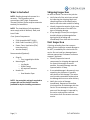
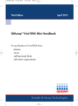
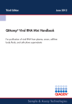
1.1.1.1 Chromasun INSTALLATION MANUAL Chromasun High-Temperature Thermal Collector System ©2011 Chromasun All Rights Reserved About the Manual NOTE: IMPORTANT! Read this entire manual before beginning installation, wiring, or usage of this product. NOTE: The installation of this equipment must comply with all National, State, and Local Codes. NOTE: By carefully reviewing the information contained in this manual, and following the instructions the risk of: improper operation, personal injury, and/or component damage will be minimized. NOTE: IMPORTANT! When in doubt please ask a Chromasun Representative! Hazard Identification Warnings and cautions appear at appropriate sections throughout this literature. Please read carefully. WARNING Indicates a potentially hazardous situation which, if not avoided, could result in death or serious injury. CAUTION Indicates a potentially hazardous situation which, if not avoided, could result in a minor or moderate injury. It may also be used to alert against unsafe practices. CAUTION Indicates a situation that could result in, equipment or property damage. For Technical Support please call: +1 408 634 4104 PVT-MCT10A-EN Page | II Table of Contents 1 2 General Information ................................................................................................................ 4 1.1 Bulk Packaging .............................................................................................................. 4 1.2 Domestic Shipment ...................................................................................................... 4 1.3 Sling Kit (Recommended Option) ................................................................................. 4 The Chromasun MCT System .................................................................................................. 5 2.1 Background ................................................................................................................... 5 2.2 Key Components ........................................................................................................... 6 2.3 2.2.1 High Temperature Micro-Concentrator (MCT-HT) ............................................ 6 2.2.2 Solar Field Controller (SFC) ................................................................................ 8 2.2.3 Power, Data, Ventilation (PDV) Interconnects .................................................. 8 Optional/Recommended Components ........................................................................ 9 2.3.1 Mount Legs (set of 2 per MCT) (Optional)......................................................... 9 2.3.2 Stand Clamps (per MCT) (Optional)................................................................... 9 2.3.3 Header Pipes (per MCT) (Optional) ................................................................... 9 3 Measurements and Weights ................................................................................................. 11 4 Pre-Installation Checklist ....................................................................................................... 13 5 4.1 Inventory Check .......................................................................................................... 13 4.2 Site Layout Checklist ................................................................................................... 13 Rigging & Installation............................................................................................................. 14 5.1 5.2 5.3 6 5.1.1 Wood Pallet ..................................................................................................... 14 5.1.2 Collapsing the Wood Pallet ............................................................................. 17 Lifting and Mounting the MCT’s ................................................................................. 19 5.2.1 Parts List........................................................................................................... 20 5.2.2 Tools List .......................................................................................................... 20 MCT Mounting Procedure .......................................................................................... 21 MCT Plumbing ....................................................................................................................... 28 6.1 6.2 7 Unpacking the MCT-HT ............................................................................................... 14 Piping Inter-Connection .............................................................................................. 28 6.1.1 Parts List........................................................................................................... 28 6.1.2 Tools List .......................................................................................................... 28 Header Connections ................................................................................................... 30 Solar Field Controller ............................................................................................................. 31 Page | 1 PVT-MCT10A-EN 7.1 SFC Hardware ............................................................................................................. 31 7.1.1 SFC PCB with Expansion Board ........................................................................ 31 7.1.2 Parts List........................................................................................................... 32 7.2 SFC Field Wiring Schematic ........................................................................................ 34 7.3 Power/Data/Ventilation (PDV) Interconnects ............................................................ 35 7.3.1 8 Parts List........................................................................................................... 35 7.4 Junction Boxes ............................................................................................................ 38 7.5 SFC Expansion Board Signals ...................................................................................... 39 Desiccant Ventilation Hardware............................................................................................ 40 PVT-MCT10A-EN Page | 2 What is Included NOTE: Reading through this manual is a necessity. The Chromasun microconcentrator (MCT) High-Temperature Thermal Collector System requires attention to detail for installation. NOTE: The installation of this equipment must comply with all National, State, and Local Codes. Core System Components: Fully Assembled MCT Unit(s) Solar Field Controller(s) (SFC’s) Power, Data, Ventilation (PDV) Interconnects(s) Junction Box(es) Recommended (Optional): Sling Kit o Four Legged Nylon Bridle Mounting Kit o Leg Stands o Stand Clamps o All required Fasteners Header Kit o Steel Header Pipes NOTE: Any materials and work required to prepare the roof for the MCT must be provided for by the installing contractors. Page | 3 Shipping Inspection As soon as the MCT arrives at the job site: Verify that all of the units have arrived by inspecting the shipping labels and comparing them to the identification data on the sales order and bill of lading Visually inspect the exterior of the crate and the visible areas of the MCTs for signs of shipping damage If any damage is found, the consignee should indicate such damage before signing the bill of lading and immediately file a claim with the carrier. Unit Inspection If, during unloading from the transport pallet, job site inspection reveals damage to an MCT, immediately file a claim with the carrier. Do not install any damaged parts without appropriate Chromasun customer support’s approval! Visually inspect the internal components for shipping damages and for material shortages as soon as possible. Concealed damage must be reported within 15 days If concealed damage is discovered, stop unpacking the shipment. If possible, take photos of the damage. The owner must provide reasonable evidence that the damage did not occur after delivery Notify the carrier of damage immediately. Request an immediate joint inspection of the damage with the carrier. Do not attempt to repair any parts until the damage is inspected by the carrier and you have received instructions from Chromasun customer service. PVT-MCT10A-EN 1 General Information 1.1 Bulk Packaging Large orders of MCT panels are shipped in bulk on reusable pallets. The MCTs are integral to the shipping pallet and must be disassembled from the pallet to be unloaded. Additional parts accompany the MCT shipping pallets in standard corrugated packaging. 1.2 Domestic Shipment Units purchased within North America will be shipped via a flat bed truck. The MCT units are stacked in sets of five (5) in reusable wooden pallets. To unload the MCT’s from the pallets the MCT’s must be removed one at a time. This is recommended to be done when the units are ready to be lifted onto the roof. For a more detailed instruction how to do this please refer to the Unpacking the MCT-HT section in the manual 1.3 Sling Kit (Recommended Option) Chromasun recommends the use of the optional Chromasun Sling Kit accessory. The four legged bridled nylon strap kit is designed to be used with a crane to transport MCT panels onto the roof by latching onto the lift points located at each corner of the MCT. The Sling Kit portion of this installation manual was written for use with our Sling Kit. If you choose to not use our Sling Kit please consult an engineer for a safe alternative lifting method using the data found in the weight and measurement section. PVT-MCT10A-EN Page | 4 2 The Chromasun MCT System 2.1 Background The Chromasun High-Temperature Thermal Collector System consists of two (2) major components: The MCT High-Temperature Collector (MCT-HT); and the Solar Field Controller. An MCT installation will typically consist of many SFC units connected to one or more Solar Field Controllers. Each SFC can support up to 40 MCTs (4 strings of 10 units each). These two components combine to provide an active tracking collector system that is able to provide consistent thermal energy up to 200°C (400°F). Typical MCT High-Temperature Concentrating System Field Layout 1A 10 1A 09 1A 08 1A 07 1A 06 1A 05 1A 04 1A 03 1A 02 1A 01 1B 01 JA1 1B 02 1B 03 1B 04 1B 05 1B 06 1B 07 1B 08 1B 09 1B 10 JB1 Field Controller 1 1C 10 1C 09 1C 08 1C 07 1C 06 1C 05 1C 04 1C 03 1C 02 1C 01 JC1 Legend 1A 10 JA1 1D 02 1D 03 1D 04 1D 05 1D 06 1D 07 1D 08 1D 09 1D 10 2A 01 2A 02 2A 03 2A 04 2A 05 2A 06 2A 07 2A 08 2A 09 2A 10 JD1 JA2 MCT-HT Field Controller 2 String Junction Box PDV Connection 1D 01 2B 01 2B 02 2B 03 2B 04 2B 05 2B 06 2B 07 2B 08 2B 09 2B 10 2C 01 2C 02 2C 03 2C 04 2C 05 2C 06 2C 07 2C 08 2C 09 2C 10 JB2 PDV Homerun HHW Supply HHW Return JC2 From Building Heating Load To Building Heating Load Figure 1: Typical Field layout of the MCT-HT System Page | 5 PVT-MCT10A-EN 2.2 Key Components 2.2.1 High Temperature Micro-Concentrator (MCT-HT) The Chromasun Micro-Concentrator MCT-HT is a next generation high performance solar collector. It has been designed purposely for rooftop integration. The MCT is low profile, lightweight and has no external moving parts; making it simple to mount and easy to maintain. Using a 20X concentration Fresnel reflector optic the MCT generates temperatures up to 200°C (400°F) and has a power output which peaks at 2.2kW, depending on location, weather, and temperature. The Chromasun MCT is perfect for process heat applications and ideal for integration with absorption refrigeration and heat pump hardware. Figure 2: Chromasun MCT-HT panels at SCU Benson Center PVT-MCT10A-EN Page | 6 Figure 4 Schematic of sunlight being concentrated within an MCT Receiver Pipe (SS 304 A213 Tube) Parallel Mirrors Figure 3 Exploded view of an MCT-HT Page | 7 PVT-MCT10A-EN 2.2.2 Solar Field Controller (SFC) A Chromasun installation will feature one or more Solar Field Controllers, which serve as the supervisory controller to the individual MCT units. Each MCT SFC can connect up to four (4) strings of ten (10) MCT Collectors, for a total of 40 MCT Collectors per SFC. Additional MCT Field Controllers can be connected to increase the number of panels controlled in the system. The Solar Field Controllers act to control the field, telling the MCTs when to turn on and off as well as providing data logging, alarm, and firmware updating functionality. The SFC takes instructions from the existing building system(s) either via analog signals (dry contacts), or over Ethernet using BacNET, Modbus, or LonWorks. Consult the MCT Operation Manual for wiring and configuration details. The SFC is connected to each string in the array by field-installed conduit home runs that terminate in a Chromasun-provided junction box. From here, each panel is connected using Chromasun-provided PDV interconnects. In this way, the SFC supplies power, data and dry ventilation air to each MCT it controls. 2.2.3 Power, Data, Ventilation (PDV) Interconnects Our Power, Data, and Ventilation Interconnects are required to provide, power, data, and ventilation from one MCT to the next. These can be seen below in Figure 5. PVT-MCT10A-EN Page | 8 2.3 Optional/Recommended Components 2.3.1 Mount Legs (set of 2 per MCT) (Optional) Our Mount Legs enable installation of the MCT at the recommended angle from a flat base. A flat base built from Unistrut (or similar structure) is required. The mounting portion of this manual was written for use with our Mount Legs. If you choose to not use our Mount Legs please consult an engineer for an alternative method. These can be seen below in Figure 5 and Figure 6. 2.3.2 Stand Clamps (per MCT) (Optional) Our Stand Clamps are used to secure the Mount Legs down to the Unistrut section. The mounting portion of this manual was written for the use with our Stand Clamps. If you choose to not use our Stand Clamps please consult an engineer for an alternative method. These can be seen below in Figure 5 and Figure 6. 2.3.3 Header Pipes (per MCT) (Optional) Our steel Header Pipes are the recommended product to use to connect the plumbing between MCT’s (Carbon and Stainless Steel available). The Header Pipe portion of this installation manual was written for use with our Header Pipes. If you choose to not use our Header Pipes please consult an engineer for an alternative method. These can be seen below in Figure 6. Page | 9 PVT-MCT10A-EN Figure 5: Components from Front View Figure 6: Components from Rear View PVT-MCT10A-EN Page | 10 3 Measurements and Weights Table 1: Physical Characteristics Dimensions Weight Unit Area Weight per Unit Area Weight per Unit Unistrut See Diagrams Below 100 kg 4.23 m2 24 kg/m2 38 kg/m 220 lb 45 sq. ft. 4.9 lb/sq. ft. 28 lb/ft Figure 7: MCT Canopy Front, Rear, Top and Side Views Page | 11 PVT-MCT10A-EN Figure 8: MCT Side View NOTE: The MCT angle and corresponding height of the rear leg vary depending on site location. The designing engineer should specify the panel angle and the distance between rows to avoid shading. The Chromasun MCT Design Manual should be referenced for more detailed information. For reference, Table 2 shows Unistrut spacing based on collector slope. Table 2: Appropriate MCT Angle and Length MCT Leg Stand Model 0 5 10 15 20 25 30 35 40 45 PVT-MCT10A-EN Suggested Angle (degrees) Dimension A 0 5 10 15 20 25 30 35 40 45 Distance Between Unistruts (mm) Dimension B 3244 3232 3195 3133 3048 2940 2809 2657 2485 2294 Distance Between Unistruts (in) Dimension B 128 127 126 123 121 116 111 105 98 90 Rear Leg Length (mm) Rear Leg Length (in) Dimension C 0 283 563 840 1110 1371 1622 1861 2085 2294 Dimension C 0 11 22 33 44 54 64 73 82 90 Page | 12 4 Pre-Installation Checklist 4.1 Inventory Check Make sure that all the units are present Check the containers to make sure they were not mistreated or damaged Inspect the MCT’s for any distortions such as: o Shattered Glass o Cracks o Obvious Bends o Collapsed/Bent Terminals 4.2 Site Layout Checklist Make sure that there is Unistrut mounted on the roof Check to make sure the pitch between the Unistrut is correct Consult the Roof Design Layout provided by the supervising engineer and check to see that the spaces between banks (side to side as well as front to back) are correct Check to see that the length of strut provided will be able to mount the required number of panels Page | 13 PVT-MCT10A-EN 5 Rigging & Installation 5.1 Unpacking the MCT-HT 5.1.1 Wood Pallet Step 1. The shipping pallet. Step 2. Remove the two top cross bars which are held down by 4X 2.5” #10 wood screws. (8 total) PVT-MCT10A-EN Page | 14 Step 3. Remove the two triangle pieces from one side of the crate only to maintain structural stability. Each side is held in place by 13X 2.5” #10 wood screws. (26 total) Step 4. Remove the two rectangular end pieces. Each end piece is held in place by 2X 2.5” #10 wood screws. As well as 2X 2” 3/8” hex cap bolts. Step 5. Crane the MCT unit away by connecting to the 4 lifting holes located at each corner of the MCT. Page | 15 PVT-MCT10A-EN Repeat steps 3 through 5 until all the MCT’s are removed PVT-MCT10A-EN Page | 16 5.1.2 Collapsing the Wood Pallet Step 1. Arrange the pieces as shown below. One row of end pieces fit nicely into the grooves between the horizontal slats in the pallet. The remaining 4 end pieces are arranged on top of the end pieces already on the pallet, upside down to interlock. The two triangle gussets are laid down on top of the end pieces, and the top cross bars are laid down on top of that. Step 2. The finalized Collapsed Wood Pallet. Page | 17 PVT-MCT10A-EN Step 3. The Wood Pallets can be stacked on top of each other when ready to be shipped back to Chromasun. Step 4. The Pallets ready to be shipped back. PVT-MCT10A-EN Page | 18 5.2 Lifting and Mounting the MCT’s This section of the MCT-HT installation manual was written for the optional mounting kit which includes the MCT Stand Legs, and the MCT Stand Clamps. If these additional items were not purchased then please consult an engineer about alternate options. Page | 19 PVT-MCT10A-EN 5.2.1 Parts List Part Part Name Quantity MCT w/ Mount Legs Refer to Order MCT Stand Clamp Refer to Order ½” Unistrut Nut Refer to Order ½” Unistrut Bolt Refer to Order 5.2.2 Tools List Part Part Name Impact Driver ½” 6 Point Socket Driver Sling kit PVT-MCT10A-EN Page | 20 5.3 MCT Mounting Procedure Step 1. Make sure that the Unistrut is laid down parallel to each other. Step 2. Loosen the short leg slightly so that it is able to swing down (needs to be loosened on both sides). Step 3. Lower the MCT panel onto the Unistrut so that the short leg is properly seated around the channel. The long leg can remain folded in its resting position. Page | 21 PVT-MCT10A-EN Step 4. Clamp down the front of the MCT using a strut nut, a stand clamp, a washer, and a bolt. Step 5. Place the next MCT down using the same methods described for the first MCT. Step 6. After lowering the next MCT, place two spacer wedges between the MCT’s taking caution to not place the blocks on the weld so that the blocks are seated flush. Then push the next MCT up against the previous MCT. Taking caution not to push too hard, but just enough so that the MCT’s are butted up against the spacer blocks. PVT-MCT10A-EN Page | 22 Step 7. Clamp down the front of the MCT’s using a strut nut, a stand clamp, a washer, and a bolt. Page | 23 PVT-MCT10A-EN Repeat Steps 5 through 7 until MCT row is complete PVT-MCT10A-EN Page | 24 Step 8. Lift the back of the MCT up (The end with the long leg). Step 9. Loosen the long leg so that it can swing down into position. Then set the strut in the channel for the long leg like the short leg. When the Legs are set tighten up both the front and the back legs! Step 10. Clamp down the back of the MCT’s using a strut nut, a stand clamp, a washer, and a bolt. Page | 25 PVT-MCT10A-EN Step 11. Place a spacer block and slide the 2nd MCT over to make sure that it is still seated tightly against the 1st MCT. Step 12. Clamp down the back of the MCT’s using a strut nut, a stand clamp, a washer, and a bolt. PVT-MCT10A-EN Page | 26 Repeat Steps 8 through 12 until MCT row is complete Page | 27 PVT-MCT10A-EN 6 MCT Plumbing 6.1 Piping Inter-Connection The piping system must be designed by a certified engineer and is to follow National, State, and Local codes. The Chromasun MCT Design Manual should be referenced to assist with hydronic design. This section was written to be used with our recommended Chromasun header Piping Kit. If this option was not purchased please consult an engineer for alternate solutions. A section is included in the Chromasun Design Manual with additional suggested connection methodologies. Chromasun recommends use of the steel header pipes within the Piping Kit to interconnect MCT units together. Given that these pipes define the pitch between MCT units, it is critical that the panel-to-panel spacing is correct. Failure to space correctly will result in the need to loosen the strut nuts and reposition the MCTs. 6.1.1 Parts List Part Part Name Quantity Steel Header Pipes Refer to Order 6.1.2 Tools List Part Part Name Welder If a Piping Kit was purchased then steel header pipes (as shown below in Figure 9) will be included in the shipment. These steel pipes will serve as interconnects between adjacent MCTs in series. PVT-MCT10A-EN Page | 28 Figure 9: MCT Piping Interconnect NOTE: For parallel connections, have the MCTs plumbed to a manifold (not provided) and then follow the piping outlined in the Basis of Design (BOD) document. The included steel pipes are to be welded to the heating fluid pipes (receivers) on the MCT. Figure 10: MCT Piping Interconnects. 3 MCT's in Series Page | 29 PVT-MCT10A-EN 6.2 Header Connections Header Connection Header Connections are beyond the scope of this manual. Please consult an engineer for an approved solution. A section is included in the Chromasun Design Manual with additional suggested connection methodologies. PVT-MCT10A-EN Page | 30 7 Solar Field Controller 7.1 SFC Hardware Power Supplies SFC PCB SFC Expansion Board Figure 11: Open SFC 7.1.1 SFC PCB with Expansion Board Figure 12: SFC PCB w/ Expansion Board Page | 31 PVT-MCT10A-EN 7.1.2 Parts List Part Part Name SFC_Enclosure SFC_Backplate SFC_PS_Backplate SFC_Power_Supply SFC_PCB SFC_PCB_Expansion SFC_Breaker_Switch PVT-MCT10A-EN Page | 32 SFC_Power Supply_DC_Jumper SFC_Common_Wire_Jumper SFC_Live_Wire_Jumper Page | 33 PVT-MCT10A-EN 7.2 SFC Field Wiring Schematic The Chromasun MCT-HT Collector System was designed to simplify installation. There are two (2) panel-to-panel interconnections between each MCT: The piping interconnection; and the power-data-ventilation (PDV) interconnection. At the end of each MCT string there is a junction box. This junction box makes it so that bare wire can be used for the homeruns between the MCT string and the Chromasun SFC. As the units were designed to be hermetically sealed, it is important to do all of the ventilation/wiring connections at the same time to maintain the interior of the panel. Avoid performing these interconnections on humid days or when there is standing water on the rooftop. MCT-HT units should always be able to vent the air inside; otherwise there could be pressure build-up or vacuum pressure inside the unit which could cause damage. For the panel-to-panel connections PDV interconnects are used to supply ventilating air, as well as power and data. For each individual string a homerun from the SFC will provide the ventilation, power, and data. Legend 1 A 1 0 J1 PDV Homerun SFC String A 1.02 String Junction Box PDV Connection Field Controller 1.01 MCT-HT 1.03 1.04 1.05 1.06 1.07 1.08 1.09 1.10 2.07 2.08 2.09 2.10 3.07 3.08 3.09 3.10 J1 SFC String B 2.01 2.02 2.03 2.04 2.05 2.06 J2 SFC String C 3.01 3.02 3.03 3.04 3.05 3.06 J3 Figure 13: 3 rows of 10 MCT's in series connected to a Desiccant box and Field Controller NOTE: The set up is intended as an example only. The field Layout should be specified by an engineer per Chromasun Design Manual. PVT-MCT10A-EN Page | 34 For the Homerun Layout and material selection, consult the field design layout provided by the design engineer. Otherwise consult the Chromasun field design white paper. 7.3 Power/Data/Ventilation (PDV) Interconnects The MCT’s may come shipped with desiccants attached to the ventilation ports. These are not to be removed until the SFC and SFC wirings are completed. Following the completion of the SFC and SFC wiring, then the PDV interconnects should be installed, and the desiccant should be removed from the ventilation ports. 7.3.1 Parts List Part Part Name Quantity PDV Interconnects Refer to Order The power, data, and ventilation are all connected with the same type of ¾” liquid tight nonmetallic flex conduit. Within the PDV interconnect, shown in Figure 14, are data and power jumpers each with a connector on both ends for connecting to the MCT. . Figure 14: Power-Data-Desiccant Interconnect NOTICE: Equipment Damage! Do not unseal the PDV ports until ready to install. The interior of the MCT is designed for indoor conditions. By opening the PDV port, the interior of the MCT is exposed to the outdoor elements. If any foreign objects (i.e. moisture, mold) get inside they may heavily damage the MCT. Also try your best to ensure that the installation of the PDV interconnects are done during dry weather. Page | 35 PVT-MCT10A-EN Step 1: Unseal the Power-Data- Port Figure 15: Sealed Power-Data Port PVT-MCT10A-EN NOTICE: Equipment Damage! Do not unseal the Power-Data port until ready to install. The interior of the MCT is designed for indoor conditions. By opening the Power-Data port, the interior of the MCT is exposed to the outdoor elements. If any foreign objects (i.e. moisture, mold) get inside they may heavily damage the MCT. Also try to ensure that the installation of the Power-Data and Desiccant interconnects are done during dry weather. Page | 36 Step 2: Have the Power-Data Interconnect ready Figure 16: Cable and Port Step 5: Connect the Power and Data cables Figure 17: Aligned Power and Data Cables Step 6: Securely fasten the conduit into the conduit fitting Figure 18: Sealed Cable to Port Page | 37 PVT-MCT10A-EN 7.4 Junction Boxes The Chromasun Junction Boxes were designed to simplify installation of Chromasun HT System. A Chromasun Junction Box connects an MCT String to the Chromasun SFC. This makes it so that bare wire can be used for the homeruns. The wire is connected to the junction panel inside of the Chromasun SFC. The bare wire is then run inside of an appropriate conduit specified in the design layout. The bare wire terminates in the string end Chromasun Junction box. Then the MCT-HT panel connects to the Chromasun Junction Box with a PDV interconnect. PVT-MCT10A-EN Page | 38 7.5 SFC Expansion Board Signals 4 5 3 4 3 FS 2 2 1 1 Figure 19: SFC Expansion Board Inputs (Red) (Do NOT Connect – Consult Commissioning Documentation) 1. 2. 3. 4. 5. SF. Heat Request Signal Solar Resource Signal MCT Attenuate Signal UPS Signal Unused (Jumper) Flow Switch Outputs (Blue) 1. 2. 3. 4. Pump/signal to BMS for solar pump Desiccant System Desiccant System Desiccant System NOTE: If your system does not have a component, confirm with your Chromasun customized order. If your Chromasun customized order confirms that you do not have that component use a wire to jumper their respective sensor inputs NOTE: The connection for the inputs are made between the “+24V” and “IN” terminals. Page | 39 PVT-MCT10A-EN Desiccant Setup 8 Desiccant Ventilation Hardware During normal operation, the air within the MCT-HT will expand and contract. In order to preserve the environment within the MCT-HT units during this “breathing”, Chromasun has engineered an active desiccant system. The active desiccant system is included as part of the Solar Field Controller and operates automatically without need for configuration or maintenance. Details on this system are not included in this manual. Please contact Chromasun for further information. PVT-MCT10A-EN Page | 40