1
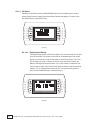
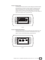
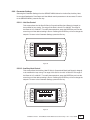
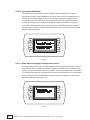
2
CM3500 Controller - ClimateMaster DOAS Water-Source Heat Pumps - Rev.: 7 Oct, 2008B
CAUTION
CAUTION - ONLY TRAINED, QUALIFIED PERSONNEL SHOULD INSTALL AND/OR SERVICE
CLIMATEMASTER EQUIPMENT. SERIOUS INJURY, DEATH AND PROPERTY DAMAGE CAN RESULT
FROM IMPROPER INSTALLATION/SERVICE OF THIS EQUIPMENT. HIGH VOLTAGE
ELECTRICAL COMPONENTS AND REFRIGERANT UNDER PRESSURE ARE PRESENT.
LIMITED WARRANTY. The goods manufactured by seller are warranted to be free from all latent
defects in material and workmanship which may be disclosed under normal use and service within
two years from date of shipment. In order for warranty to be valid, a START-UP REPORT must be
completed and returned to the factory. If the report is not sent back, warranty will be voided on the
equipment. If it is found that the goods contained defects at the time such goods were furnished by
the seller, seller will either repair or replace the defective part or parts at sellers option. This warranty
to repair or replace is the exclusive remedy and is expressly limited to the materials furnished by the
seller. All replacements or repairs shall be F.O.B. Oklahoma City, OK. The seller shall not be liable
for labor cost incurred in diagnosing the problem, in removal or replacement of the part or parts so
repaired or replaced. Accordingly, seller shall not be liable for any consequential damages, whether
to person or property, caused by defects in goods. This warranty does not apply to any goods which
may have been repaired or altered in any way outside of our factory, so as to affect its stability in
our judgment, nor does this warranty apply to any goods which have been subjected to misuse,
negligence or accident. This warranty is in lieu of all other warranties, expressed or implied, including
any implied warranty of merchantability, and extends only to the original purchaser.
CM3500 Controller - ClimateMaster DOAS Water-Source Heat Pumps - Rev.: 7 Oct, 2008B
3
4
CM3500 Controller - ClimateMaster DOAS Water-Source Heat Pumps - Rev.: 7 Oct, 2008B
TABLE OF CONTENTS
1 - Installation........................................................................................................................................8
1.2 - Sensor Installation.............................................................................................................................8
1.2.1 - Duct-Mount Sensor..............................................................................................................8
1.2.2 - Remote Room Sensor(s)......................................................................................................9
1.3 - Auxiliary Air Heating Control Wiring..................................................................................................9
1.3.1 - Auxiliary Heating - Dry Contact Closure...............................................................................9
1.3.2 - Auxiliary Heating - Proportional Signal.................................................................................9
1.4 - Wiring for Ventilation Air....................................................................................................................10
1.5 - Mounting the Remote Terminal.........................................................................................................10
1.5.1 - Installing the Remote Terminal.............................................................................................11
1.6 - Overview............................................................................................................................................11
1.7 - Remote Terminal Troubleshooting.....................................................................................................11
1.7.1 - Troubleshooting the Remote Terminal..................................................................................11
2 - IAQ Controller Details.......................................................................................................................12
- Menu Overview and General Instructions.........................................................................................12
2.2 - Main Menu........................................................................................................................................13
2.2.1 - Temperature Settings...........................................................................................................13
2.2.1.1 - Supply Air Temperature Setpoint...........................................................................14
2.2.1.2 - Zone Reset Setpoints............................................................................................14
2.2.1.3 - Operation of the Remote Room Sensor................................................................15
2.2.2 - Un-Occupied Settings...............................................................................16
2.2.3 - Temporary Occupancy.........................................................................................................17
2.2.4 - Occupancy Schedule...........................................................................................................17
2.2.4.1 - Schedule Options..................................................................................................18
2.2.4.1.1 - Current Schedule.................................................................................18
2.2.4.2 - Temporary Holidays...............................................................................................19
2.2.4.3 - Annual Holidays.....................................................................................................19
2.2.4.4 - Set Time.................................................................................................................20
2.2.5 - Unit Revision.........................................................................................................................20
2.3 - Service Menu....................................................................................................................................21
2.3.1 - Unit Status............................................................................................................................22
2.3.1.1 - Modes & Time........................................................................................................22
2.3.1.2 - Outside Air Dewpoint.............................................................................................23
2.3.1.3 - Outside Air Temperature Setpoints........................................................................23
2.3.1.4 - I/O Status...............................................................................................................24
2.3.1.4.1 - Digital Inputs (Binary)...........................................................................24
2.3.1.4.2 - Analog Inputs.......................................................................................25
2.1
CM3500 Controller - ClimateMaster DOAS Water-Source Heat Pumps - Rev.: 7 Oct, 2008B
5
- Digital Outputs (Binary)........................................................................25
2.3.1.4.4 - Analog Outputs....................................................................................26
2.3.1.4.5 - Room Sensor Data...............................................................................26
2.3.1.4.3
- Parameter Settings...............................................................................................................27
2.3.2.1 - Hot Gas Control.....................................................................................................27
2.3.2.2 - Auxiliary Heat Control............................................................................................27
2.3.2.3 - Un-Occupied Deadbands......................................................................................28
2.3.2.4 - Room Reset of Leaving Air Temperature Control..................................................28
2.3.2.5 -Heat Wheel Control Setpoints...............................................................................29
2.3.2
- Sensor Offsets......................................................................................................................30
2.3.4 - Pressure Cutouts..................................................................................................................30
2.3.5 - Glycol Ratio..........................................................................................................................31
2.3.3
- Factory Configuration........................................................................................................................31
2.4.1 - Refrigerant............................................................................................................................32
2.4.2 - Set as Heat Pump................................................................................................................32
2.4.3 - Sequential Heating...............................................................................................................32
2.4.4 - Room Reset of Leaving Air Temperature Control.................................................................32
2.4.5 - Unoccupied Control.............................................................................................................32
2.4.6 - Heat Wheel VFD...................................................................................................................33
2.4.7 - Dual Refrigerant Circuits.......................................................................................................33
2.4.8 - Room Reset of Leaving Air Temperature Control Settings...................................................33
2.4.9 - Building Automation Communications.................................................................................34
2.5 - Alarm Menu.......................................................................................................................................35
2.5.1 - Alarm Screen........................................................................................................................35
2.5.2 - Low Suction Pressure...........................................................................................................35
2.5.3 - General Fault........................................................................................................................36
2.5.4 - High Discharge Pressure......................................................................................................36
2.5.5 - Multiple Low Pressure in Heat Pump Mode.........................................................................37
2.5.6 - High Discharge Pressure Circuit B.......................................................................................37
2.5.7 - Low Suction Pressure Circuit B............................................................................................37
2.5.8 - Outside Air Temperature Sensor Failure...............................................................................37
2.5.9 - Supply Air Temperature Sensor Failure................................................................................38
2.5.10 - Room Reset Network Failure..............................................................................................38
2.5.11 - Alarm History Screen..........................................................................................................38
2.4
2.5.12 - Air Filter Service Required..................................................................................................38
2.6 - Air Filter Service Required................................................................................................................39
6
CM3500 Controller - ClimateMaster DOAS Water-Source Heat Pumps - Rev.: 7 Oct, 2008B
3 - Hardware Details............................................................................................................................40
3.1 - Programmable Controller..................................................................................................................40
3.2 - Remote Terminal...............................................................................................................................40
3.3 - Remote Room Sensor.......................................................................................................................40
3.4 - Suction Pressure Transducer............................................................................................................40
3.5 - Discharge Pressure Transducer........................................................................................................41
3.6 - Supply Air Temperature Sensor.........................................................................................................41
3.7 - Outside Air Temperature and Relative Humidity Sensor...................................................................41
3.8 - Air Flow Switch..................................................................................................................................41
CM3500 Controller - ClimateMaster DOAS Water-Source Heat Pumps - Rev.: 7 Oct, 2008B
7
1. - Installation
1.1 - Humidity and Temperature Control Package
Your ClimateMaster controller is designed for precise monitoring and control of air temperature and relative
humidity (RH) within a conditioned environment.
This CM3500 control system is easy to install and operate. It features a wall-mountable remote display
terminal which allows you to view and adjust set points and modes of operation. It also indicates the
operating status of major components inside of the DOAS unit.
Most sensors and inputs have been factory-installed and wired inside of the DOAS unit. In most cases, you
need only mount and wire the supply air temperature sensor and the remote display. The terminal, which is
simply an interface tool, contains no sensors. You do not need to install it in the space. If purchased with
your system, remote room sensors may require mounting as well.
1.2 - Sensor Installation
Your controller is provided with a duct-mount supply air temperature sensor. It may also come with one or
multiple remote room sensors depending on what option was selected when the equipment was ordered.
1.2.1 - Duct-Mount Sensor
8
A duct-mount sensor is normally used when continuous blower operation is desired or required. A
duct-mount sensor helps ensure consistent temperature and humidity levels throughout the space.
One drawback of this sensor is that it relies on a continuous stream of air moving past it. Using
a duct-mount sensor with a non-continuous blower may lead to short-cycling of the refrigeration
compressor.
Install the duct-mount sensor in the supply air duct downstream from an auxiliary heater (if used). Do
not mount the sensor in a section of duct where false readings may occur due to dead air regions,
solar heat gain or thermal losses in winter. Do not mount the sensor where water is likely to drip on it.
Liquid moisture may damage the humidity sensing element in the sensor. Run two, 18 gauge (0-500
feet) or two, 24 gauge (0-100 feet) wires from the sensor to the labeled terminal strip in the control panel
of the DOAS unit. See your wiring schematic for connection details. Note that undersized wiring will
cause inaccurate sensor readings. Do not run sensor wiring adjacent to or in the same conduit as
wires carrying more than 24 VAC.
CM3500 Controller - ClimateMaster DOAS Water-Source Heat Pumps - Rev.: 7 Oct, 2008B
1.2.2 - Remote Room Sensor(s)
ClimateMaster DOAS units ordered with the room reset of supply air temperature (RRSAT) option are
supplied with a remote room sensor. Up to four of these sensors may be wired to the system.
Figure 1
This wall-mountable display is an IP30 rated device. Ambient conditions must be between 32.0ºF and
120.0ºF and less than 85% RH. The controller’s RS485 serial interface communicates via three-way
plug-in terminals. Use a twisted pair plus shielded cable, 20-22 AWG. Total length of the network must
not exceed 1,500 feet. The capacitance between the wires must not exceed 90 pF/M. See your wiring
schematic for connection details. Note that undersized wiring will cause inaccurate sensor readings.
These remote devices require a separate 24Vac 50/60HZ 1.5VA power connection. Provide a
dedicated 250mAT fuse for each sensor. Use a class 2 safety transformer with a minimum rating
of 4VA. If the sensor is wired to F1 and F2 of the DOAS unit control panel terminal, G0 must be
connected to F2.
Do not run sensor wiring adjacent to, or in the same conduit as wires carrying more than 24 VAC.
1.3 - Auxiliary Air Heating Control Wiring
Note: You must use the ClimateMaster CM3500 control system to interlock the room heating system. This
prevents wide fluctuations in room air temperature. It also prevents the heater from trying to heat the room
while the DOAS unit is running in the cooling mode.
1.3.1 - Auxiliary Heating - Dry Contact Closure
The standard ClimateMaster CM3500 Controller provides a dry contact closure to operate the auxiliary
space heating. The contact closes to energize a heater (by others) which has its own control transformer.
Run two wires from the thermostat terminal blocks on the heater to the labeled terminal strip on the
control panel of the DOAS unit. See your wiring schematic for connection details.
1.3.2 - Auxiliary Heating - Proportional Signal
As an option, ClimateMaster will provide a proportional 0-10 VDC direct-acting signal to modulate a
heating coil control valve or other auxiliary modulating heater. Most proportional valves have either
three or four terminals for field-installed wiring.
CM3500 Controller - ClimateMaster DOAS Water-Source Heat Pumps - Rev.: 7 Oct, 2008B
9
• Four-terminal valves have two terminals for 24 VAC power and two terminals for the signal input.
• Three-terminal valves have one terminal for the “hot” 24 VAC input, a second terminal for the
“positive” signal input and a third, common terminal for the “neutral” 24 VAC input and the
“negative” signal input.
You must follow the instructions included with the valve cut sheet. Observe the proper polarity or you
may damage both the valve and the controller. See the unit wiring schematic for information on signal
wire connection points.
1.4 - Wiring for Ventilation Air
ClimateMaster DOAS units have a set of dry contacts to interlock with a field-supplied exhaust blower. The
contacts close during the occupied mode to energize this blower.
See your wiring schematics and the DOAS unit’s installation and operation manual for more details on
installing and controlling ventilation air intakes.
1.5 - Mounting the Remote Terminal
The remote terminal must be located in a dry, non-corrosive environment. Operating conditions must be
between 0.0ºF and 140.0ºF and less than 90% RH. Moisture or chemicals can damage the circuitry of the
display. The display can either be affixed directly to the DOAS unit (indoor models only) or located up to 20
feet away using the cable that came with the display.
Figure 2
10
CM3500 Controller - ClimateMaster DOAS Water-Source Heat Pumps - Rev.: 7 Oct, 2008B
1.5.1 - Installing the Remote Terminal
The remote terminal is an IP40 device and is powered through the cable provided. If a longer length is
required, a standard 24 AWG, 6 conductor phone cable may be used up to 150 feet. For location of the
sensor up to 1,500 feet, use 22 AWG, 3 twisted pair cable. See your wiring schematic for connection
details. Pull the cord and connector through the hole in the back of the mounting bracket. Attach the
bracket to the wall. After plugging the cord into the back of the remote display, feed any extra wiring
back into the hole of the mounting bracket and gently snap the remote display into the bracket.
Caution: Do not run the remote terminal wiring in the same conduit as,
or adjacent to wires carrying over 30 volts!
Using and Adjusting the Remote Display
1.6 - Overview
ClimateMaster’s CM3500 microprocessor controller is a powerful, flexible controller with many useful
features including:
• Display of room air temperature, relative humidity and refrigerant pressures;
• Display of equipment operating status such as dehumidification, cooling, and heating modes;
• Display of alarms or abnormal conditions such sensor failures or tripped safety controls;
• An optional seven-day occupancy timer which can control outdoor air dampers;
• A convenient, easy-to-understand person/machine interface, which allows the operator to view and change
set points and time schedules. This interface or “remote terminal” can be installed up to 1,500 feet away
from the DOAS unit.
1.7 - Remote Terminal Troubleshooting
The remote terminal allows the operator to monitor the operation of the DOAS unit and view the alarm
screens and history to insure proper DOAS unit operation. It is important that the remote terminal remains
functional for safe and efficient unit operation. If you think the remote terminal is not functioning correctly,
refer to the table in Section 1.7.1 that follows.
1.7.1 - Troubleshooting the Remote Terminal
Problem
Solution
No LEDS lit on the remote terminal No power is
getting to the remote terminal.
Check field wiring between remote terminal
and controller.
Remote terminal shows: “NO LINK” The display
address has been altered.
Press the UP, ENTER and DOWN keys together
for 4 seconds and set the display address to 32.
Red alarm LED is lit. The system has
experienced an alarm and is waiting for it to
be acknowledged.
Press ENTER from the Alarm Screen. If the red
LED stays lit, clear the alarm condition and then
press ENTER from the Alarm Screen.
If the remote terminal is not functioning after review of the above, consult ClimateMaster’s Technical Service
Department at (405) 745-6000.
CM3500 Controller - ClimateMaster DOAS Water-Source Heat Pumps - Rev.: 7 Oct, 2008B
11
2 - IAQ Controller Details
Figure 3
2.1 - Menu Overview and General Instructions
Your ClimateMaster CM3500 Controller is pre-programmed and configured at the factory for use in the
application you have specified. The remote terminal allows the operator to monitor the operation and adjust
the setpoints of the DOAS unit. The remote terminal has an LCD screen and 6 keys. The keys on the left
hand side of the remote terminal, top to bottom, are the ALARM key shown as an alarm bell, PROGRAM key
abbreviated “Prg” and the ESCAPE key abbreviated “Esc.” The keys on the right hand side of the remote
terminal, top to bottom, are the UP key shown as an up arrow, the ENTER key shown as a left arrow and the
DOWN key shown as a down arrow. Pressing the Esc key from the MAIN MENU will display the unit’s menu
selections. Pressing Esc from any other screen will take you back one screen, while pressing ENTER will
select that screen. If setpoints or selections can be altered on a screen, the ENTER key will cycle through
those items. Once the cursor is over an item, the UP and DOWN arrow keys will modify the setting. Numeric
values will require that the ENTER key be pressed to accept the value. An “on” or “off “ selection will be
altered as soon as the UP or DOWN keys are pressed.
To view the alarms from any menu, simply press the ALARM key. The UP and DOWN keys will show any
active alarm. Any time an alarm is triggered, the red LED behind the ALARM key will light. This LED will
remain on until the alarm is acknowledged. Alarm acknowledgement and history instructions are shown on
the main Alarm Screen. To escape from the alarm screens, press the Esc key.
Screens which display a small up arrow in the upper right and a small down arrow in the lower left are part
of a series of screens which can be accessed by pressing either the UP or DOWN arrow keys. If the operator
has not pressed a key for 5 minutes, the remote terminal will return to the Home Screen.
12
CM3500 Controller - ClimateMaster DOAS Water-Source Heat Pumps - Rev.: 7 Oct, 2008B
2.2 - Main Menu
Pressing the Esc key from the Home Screen displays the MAIN MENU. This menu allows the operator to
modify the TEMPERATURE SETTINGS set a Temporary Occupancy, change the Occupancy Schedule and
view the Unit Revision. To return to the Home Screen, press the Esc key.
Figure 4
2.2.1 - Temperature Settings
The temperature settings for your unit can be modified from this menu. Select the appropriate item
with the UP and DOWN keys and press the ENTER key to select. To return to the MAIN MENU, press
the Esc key.
Figure 5
CM3500 Controller - ClimateMaster DOAS Water-Source Heat Pumps - Rev.: 7 Oct, 2008B
13
2.2.1.1 - Supply Air Temperature Setpoint
This screen will only be shown if the room reset of leaving air temperature (RRLAT) option
is not selected. This screen allows the supply air temperature setpoint to be modified. The
value of the setpoint ranges from 45.0ºF to 99.9ºF with a 72.0ºF default. To modify the
setpoint, press the ENTER key and use the arrow keys until the desired setting is shown.
Pressing the ENTER key will now change the setpoint. To return to the TEMPERATURE
SETTINGS MENU, press the Esc key.
Figure 6
2.2.1.2 - Zone Reset Setpoints
In the Room Reset of Leaving Air Temperature (RRLAT) mode of operation, the supply air
temperature setpoint is modified based upon the actual zone air temperature, the zone air
temperature setpoint and the high and low limits which are set on this screen. This mode
requires the remote room sensor be installed in the conditioned space. For operation of
the remote room sensor, see Section 2.2.1.3. As the zone air temperature increases above
the zone air setpoint, the Leaving Air Temperature (LAT) setpoint is continuously modified
to achieve a faster return to setpoint. The same logic applies to a decrease under setpoint.
The high and low limits make up the band of the possible zone air temperature setpoint.
In this mode, the Home Screen and the Analog Output Screen will display the actual zone
air temperature instead of the supply air temperature. This screen will only be shown if the
RRLAT option is selected. This screen allows the Zone Reset Setpoint as well as the High
and Low Limits to be modified. The value of the Zone Reset Setpoint ranges from 55.0ºF
to 95.0ºF, with a default of 72.0ºF. To modify the setpoint, press the ENTER key and use the
arrow keys until the desired setting is shown. Pressing the ENTER key will now change the
setpoint. The value of the High Limit ranges from 40.0ºF to 140.0ºF, with a 90.0ºF default
and the value of the Low Limit ranges from 35.0ºF to 70.0ºF, with a 60.0ºF default. To return
to the TEMPERATURE SETTINGS MENU, press the Esc key.
14
CM3500 Controller - ClimateMaster DOAS Water-Source Heat Pumps - Rev.: 7 Oct, 2008B
Figure 7
2.2.1.3 - Operation of the Remote Room Sensor
The remote room sensor supplied with the RRLAT option will allow modification of the Zone
Air Setpoint. This can only be changed on the remote room sensor assigned as address
2. Pressing the UP or DOWN buttons will display and flash the current setpoint. Pressing
the UP or DOWN buttons again will change the setpoint in 0.1ºF increments. Pressing and
holding down these buttons will allow for a faster scroll of the setpoint. The last displayed
value will become the setpoint after a few moments. The setpoint will assume the value of
the last device to modify it, either the remote room sensor or the remote terminal.
Figure 8
The remote room sensor displays the occupancy status of the unit. A house icon is
shown to the left of the temperature. If it is empty, the unit is in the un-occupied mode. If
a figure of a person is displayed within the house icon, the unit is in the occupied mode.
The remote room sensor can also be used to override the occupancy of the unit for a few
hours. Press the SLEEP button, symbolized as a crescent moon on the left side of the
sensor, fourth button from the top. This will display “1” and the crescent moon. The unit will
CM3500 Controller - ClimateMaster DOAS Water-Source Heat Pumps - Rev.: 7 Oct, 2008B
15
now be occupied for one hour. Pressing the button multiple times will allow for up to nine
hours of occupancy. To cancel the occupancy set from the remote room sensor, simply
press the SLEEP button again, or set the hours to zero. When the crescent moon icon
disappears, the occupancy override is cancelled.
The bottom left button on the remote room sensor flips the large temperature and small
humidity display to the large humidity and small temperature display for a few seconds.
This allows the humidity to be displayed in a larger font.
All of the other buttons on the left of the remote room sensor are disabled for this
application. Pressing them will display an icon of a lock. The remote room rensor will flash
“ALr” to indicate that an alarm has occurred. The display of the current alarm must be
done from the remote terminal. The remote room sensor will flash “oLn” to indicate that the
sensor is offline from the controller.
To change the internal setable parameters of the remote room sensor, see Section 3.5.
2.2.2 - Unoccupied Settings
This screen will only be shown if the Zone Reset and the Unoccupied Control is selected in the
Factory Configuration Screen. These setpoints will only be used in the unoccupied mode. The range
of the Cooling Setpoint is from the current Heating Setpoint setting to 95.0ºF with a default of 65.0ºF.
The range of the Heating Setpoint is from 40.0ºF to the current Cooling Setpoint setting with a default
of 85.0ºF. To modify the setpoint, press the ENTER key and use the arrow keys until the desired
setting is shown. The range of the Unoccupied Humidity Setpoint is 20.0% to 99.9%, with a default
of 60.0%. To modify the setpoint, press the ENTER key and use the arrow keys until the desired
setting is shown. To return to the TEMPERATURE SETTINGS MENU, press the Esc key.
Figure 9
16
CM3500 Controller - ClimateMaster DOAS Water-Source Heat Pumps - Rev.: 7 Oct, 2008B
2.2.3 - Temporary Occupancy
This screen allows the operator to set the unit into occupied mode for a preset amount of time. Press
the ENTER key and enter in the hours and minutes you would like the unit to be temporarily in the
occupied mode. When the cursor is blinking over the “Press Prg to set” message, pressing the Prg
key will override the schedule and allow the unit to be temporarily occupied. The screen will now
show “Override On.” To clear this occupied override, set the hours and minutes to zero and press the
Prg key. The screen will now show “Override Off.” To return to the MAIN MENU, press the Esc key.
Figure 10
2.2.4 - Occupancy Schedule
Selecting the SCHEDULE SETUP from the MAIN MENU takes you to the OCCUPANCY SCHEDULE
MENU. This menu allows you to access and adjust the Schedule Options, Temporary Holidays,
Annual Holidays and Time settings. To return to the MAIN MENU, press the Esc key.
Figure 11
CM3500 Controller - ClimateMaster DOAS Water-Source Heat Pumps - Rev.: 7 Oct, 2008B
17
2.2.4.1 - Schedule Options
This screen selects the number of occupancy schedules to be active. Setting at least one
allows the occupancy schedule timing to be set from the Current Schedule Screen. If the
number of active schedules is left at zero, no occupancy scheduling will be active. To
return to the OCCUPANCY SCHEDULE MENU, press the Esc key.
Figure 12
2.2.4.1.1 - Current Schedule
This screen sets the occupancy timing for the selected day of the week (DOW)
at the bottom of the screen. Select the schedule to modify the start time and
stop time. This is the time band that the unit will be in the occupied mode. All
times are set in the 24 hour format. As the DOW is selected, the UP and DOWN
keys allow for Monday, Tuesday, Wednesday, Thursday, Friday, Saturday,
Sunday and any holiday to be occupied during that time. Up to 10 schedules
can be active at any time. These allow for different start and stop times on
various days of the week, weekends or programmed holidays. To return to the
OCCUPANCY SCHEDULE MENU, press the Esc key.
Figure 13
18
CM3500 Controller - ClimateMaster DOAS Water-Source Heat Pumps - Rev.: 7 Oct, 2008B
2.2.4.2 - Temporary Holidays
The Temporary Holiday settings are for holidays that change dates from year to year, such
as Memorial Day or Thanksgiving. Up to 10 different temporary holidays can be set from
this screen. Select the number to assign to the Annual Holiday and then select the Start
Date and the End Date for that holiday. To return to the OCCUPANCY SCHEDULE MENU,
press the Esc key.
Figure 14
2.2.4.3 - Annual Holidays
The Annual Holiday settings are for holidays with dates that remain constant year to year,
such as New Years Day and the 4th of July. Up to 10 different annual holidays can be set
from this screen. Select the number to assign to the Annual Holiday and then select the
Start Date and the End Date for that holiday. To return to the OCCUPANCY SCHEDULE
MENU, press the Esc key.
Figure 15
CM3500 Controller - ClimateMaster DOAS Water-Source Heat Pumps - Rev.: 7 Oct, 2008B
19
2.2.4.4 - Set Time
This screen allows the time, date and day of week to be set. To modify these settings,
press the ENTER key until the cursor is over the appropriate item and use the arrow keys
until the desired setting is shown. All times are set in the 24 hour format. Pressing the
ENTER key will step to the next item. If any item was modified, the message “Enter to
Set” will be shown. Press the ENTER key to change the time and date. To return to the
OCCUPANCY SCHEDULE MENU, press the Esc key.
Figure 16
2.2.5 - Unit Revision
The Unit Revision Screen shows the version of the application program that is running along with the
release date of the software. This information should be passed to ClimateMaster in the event a service
call is necessary. The SERVICE MENU and Factory Configuration are accessible ONLY from this screen.
Figure 17
20
Press the UP and DOWN keys at the same time to display these menus. To return to the MAIN
MENU, press the Esc key.
CM3500 Controller - ClimateMaster DOAS Water-Source Heat Pumps - Rev.: 7 Oct, 2008B
Figure 18
2.3 - Service Menu
Selecting the SERVICE MENU will display the Login Screen. Enter the service password, 1234, and press
ENTER. The SERVICE MENU allows the Unit Status, Parameter Settings, Sensor Offsets and Pressure
Cutouts to be accessed. To return to the Unit Revision Screen, press the Esc key. The password is bypassed
for 5 minutes after it is first entered. This is displayed on the Login Screen with the text, “Still Logged In,
Press PRG to Enter.” To re-enter the SERVICE MENU without entering the password, just press the Prg key.
Figure 19
CM3500 Controller - ClimateMaster DOAS Water-Source Heat Pumps - Rev.: 7 Oct, 2008B
21
2.3.1 - Unit Status
Selecting Unit Status from the MAIN MENU allows for the Modes & Time, Outside Air Dewpoint,
Outside Air Temperature and I/O Status to be accessed. To return to the SERVICE MENU, press the
Esc key.
Figure 20
2.3.1.1 - Modes & Time
Selecting Modes & Time from the SERVICE MENU displays a text explanation of the unit.
The Occupied mode either Occupied or Un-Occupied is shown as well as the unit status.
The Unit Status will show one of the following states: Unit Off, Unconditioned Air, Unit
Cooling, Dehumidifying, Unit Heating or Low Air Flow. The Compressor On/Off, Auxiliary
Heat On/Off and current date and time will also be shown. To return to the Unit Status
Screen, press the Esc key.
Figure 21
22
CM3500 Controller - ClimateMaster DOAS Water-Source Heat Pumps - Rev.: 7 Oct, 2008B
2.3.1.2 - Outside Air Dewpoint
The factory set Outside Air Dewpoint Setpoint and Deadband can be modified on this
screen. The factory setpoint for the Dewpoint and Deadband is preset before the controller
is shipped. Modification to these settings should only be done by a trained technician. To
modify these setpoints, press the ENTER key until the desired setpoint is selected and use
the arrow keys until the desired setting is shown. The range of the Outside Air Dewpoint is
0.0º to 99.9ºF with a default of 60.0ºF. The range of the Deadband is 0.0º to 9.9ºF with a
default of 3.0ºF. The Actual Outside Air Dewpoint is shown for reference. Pressing the ENTER
key will now change the setpoint. To return to the Unit Status Screen, press the Esc key.
Figure 22
2.3.1.3 - Outside Air Temperature Setpoints
This screen shows the Cooling and Heating Setpoints as well as the Deadband to be used
for each. The range of the Cooling Setpoint is from the current Heating Setpoint setting
to 95.0ºF, with a default of 70.0ºF. The range of the Heating Setpoint is from 40.0ºF to the
current Cooling Setpoint setting with a default of 68.0ºF. To modify the setpoint, press the
ENTER key and use the arrow keys until the desired setting is shown. Pressing the Enter
key will now change the setpoint. The range of Deadband is 0.0º to 9.9ºF, with a default of
1.0ºF. The Actual Outside Air Temperature is shown for reference. Pressing the ENTER key
will now change the setpoint. To return to the Unit Status Screen, press the Esc key.
Figure 23
CM3500 Controller - ClimateMaster DOAS Water-Source Heat Pumps - Rev.: 7 Oct, 2008B
23
2.3.1.4 - I/O Status
Selecting the I/O Status from the SERVICE MENU allows for the Digital Inputs, Analog
Inputs, Digital Outputs, Analog Outputs and Room Sensor Data display. To return to the
Unit Status Screen, press the Esc key.
Figure 24
2.3.1.4.1 - Digital Inputs (Binary)
The Digital Inputs Screen will show the state of the contacts wired into the port
J5 of the controller. This screen is provided for troubleshooting of the control
system. Input Point ID1 will show the status of the Air Flow Switch, “On” if air
flow is present and “Off” if there is no air flow. Input Point ID3 will show the
status of the Digital Occupied Contact, “On” if this contact is made and “Off”
if this contact is open. Input Point ID4 will show the status of the General Fault
Contact, “On” if a general fault exists and “Off” if no general fault exists. To
return to the I/O Status Screen, press the Esc key.
Figure 25
24
CM3500 Controller - ClimateMaster DOAS Water-Source Heat Pumps - Rev.: 7 Oct, 2008B
2.3.1.4.2 - Analog Inputs
The Analog Inputs Screen shows the current readings of the Suction Pressure,
Discharge Pressure, Outside Air Humidity, Outside Air Temperature and the
Supply Air Temperature. If your unit comes standard with dual refrigerant
circuits, the Suction Pressure and Discharge Pressure of circuit B is also
displayed. This screen is provided for troubleshooting of the control system. To
return to the I/O Status Screen, press the Esc key.
Figure 26
2.3.1.4.3 - Digital Outputs (Binary)
The Digital Output Screen will show the state of the relays wired into port J12
of the controller. This screen is provided for troubleshooting of the control
system. To return to the I/O Status Screen, press the Esc key.
Figure 27
CM3500 Controller - ClimateMaster DOAS Water-Source Heat Pumps - Rev.: 7 Oct, 2008B
25
2.3.1.4.4 - Analog Outputs
The Analog Output Screen shows the current readings of the Hot Gas
Command on Y1 and the Auxiliary Heating Command on Y2. If your unit comes
standard with a heat wheel VFD for freeze protection, then the VFD Command
is shown on Y3. This screen will also show the Supply Air Temperature or
the Zone Temperature since it relates to the Hot Gas and Auxiliary Heat
Commands. The calculated Dewpoint is also shown on this screen. This screen
is provided for troubleshooting of the control system. To return to the I/O
Status Screen, press the Esc key.
Figure 28
2.3.1.4.5 - Room Sensor Data
This screen is only shown if the RRLAT option is selected in the Factory
Configuration of the unit. The Remote Room Sensor Temperature and Humidity
Readings wired into the system are shown on this screen by address. The
average of these sensors is shown as well. This screen is provided for
troubleshooting of the control system. To return to the I/O Status Screen press
the Esc key.
Figure 29
26
CM3500 Controller - ClimateMaster DOAS Water-Source Heat Pumps - Rev.: 7 Oct, 2008B
2.3.2 - Parameter Settings
Selecting the Parameter Settings from the SERVICE MENU allows for the Hot Gas, Auxiliary Heat,
Unoccupied Deadbands, Zone Reset and Heat Wheel control parameters to be accessed. To return
to the SERVICE MENU, press the Esc key.
2.3.2.1 - Hot Gas Control
This screen allows the Hot Gas PI Gain (or Proportional Band) and Reset (or Integral) to
be modified for loop tuning. The range of the Gain is from 0.0º to 999.9ºF. The range of
the Reset is 0.0° to 999.9° F. To modify these setpoints, press the ENTER key and use the
arrow keys until the desired setting is shown. Pressing the ENTER key will now change the
setpoint. To return to the Parameter Settings, press the Esc key.
Figure 30
2.3.2.2 - Auxiliary Heat Control
This screen allows the Auxiliary Heat PI Gain (or Proportional Band) and Reset (or Integral)
to be modified for loop tuning. The range of the Gain is from 0.0º to 999.9ºF. The range of
the Reset is 0.0° to 999.9° F. To modify these setpoints, press the ENTER key and use the
arrow keys until the desired setting is shown. Pressing the ENTER key will now change the
setpoint. To return to the Parameter Settings, press the Esc key.
Figure 31
CM3500 Controller - ClimateMaster DOAS Water-Source Heat Pumps - Rev.: 7 Oct, 2008B
27
2.3.2.3 - Unoccupied Deadbands
This screen will only be shown if the Unoccupied Control is selected in the Factory
Configuration Screen. These deadbands will only be used in the unoccupied mode. The
Cooling and Heating Deadband is used to prevent short cycling and is added to the
Cooling Setpoint and subtracted from the Heating Setpoint. The Humidity Deadband
is added to the Setpoint. To modify the Deadbands, press the ENTER key and use the
arrow keys until the desired setting is shown. Pressing the ENTER key will now change
the deadbands. The range of both Deadbands is 0.0º to 9.9ºF. To return to the Parameter
Settings, press the Esc key.
Figure 32
2.3.2.4 - Room Reset of Leaving Air Temperature Control
This screen will only be shown if the Room Reset option is selected. This screen allows the
Zone Reset PI Gain (or Proportional Band) and Reset (or Integral) to be modified for loop
tuning. The range of the Gain is from 0.0º to 99.9ºF. The range of the Reset is 0.0° to 999.9°
F. To modify these setpoints, press the ENTER key and use the arrow keys until the desired
setting is shown. Pressing the ENTER key will now change the setpoint. To return to the
Parameter Settings, press the Esc key.
Figure 33
28
CM3500 Controller - ClimateMaster DOAS Water-Source Heat Pumps - Rev.: 7 Oct, 2008B
2.3.2.5 - Heat Wheel Control Setpoints (Figure 36)
This screen will only be shown if the Heat Wheel VFD option is selected in the Factory
Configuration. This screen allows modification of the Heat Wheel PI Gain (or Proportional
Band) and Reset (or Integral) for loop tuning. It also allows for modifying the Heat Wheel
Humidity Setpoint, as well as displaying the Heat Wheel Humidity from the internal humidity
sensor. The range of the Gain is from 0.0% to 99.9%. The range of the Reset is 0.0º 999.9º
F. The range for the Setpoint is from 0.0% to 99.9%. To modify these setpoints, press the
ENTER key until the desired setpoint is selected and use the arrow keys until the desired
setting is shown. Pressing the ENTER key will now change the setpoint. To return to the
Parameter Settings, press the Esc key.
Figure 36
CM3500 Controller - ClimateMaster DOAS Water-Source Heat Pumps - Rev.: 7 Oct, 2008B
29
2.3.3 - Sensor Offsets
This screen allows the control values of the analog input points to be adjusted if calibration shows
these devices to be inaccurate. The range of these offsets is from -99.9 to 99.9. Care must be used
when applying an offset to an analog value as erratic operation can result. To modify the offsets,
press the ENTER key until the desired offset is selected and use the arrow keys until the desired
setting is shown. Pressing the ENTER key will now change the offset. To return to the SERVICE
MENU, press the Esc key.
Figure 34
2.3.4 - Pressure Cutouts
This screen simply displays the Refrigerant Selection, High Discharge Pressure and Low Suction
pressure cutout values for the appropriate refrigerant selected. The operator cannot change these
settings. The Cooling Mode Low Pressure Trip is shown because if the unit is set as a heat pump,
and the compressor is used for heating, the low pressure trip is varied based upon the glycol ratio.
See Section 2.5.4 for details. To return to the SERVICE MENU, press the Esc key.
Figure 35
30
CM3500 Controller - ClimateMaster DOAS Water-Source Heat Pumps - Rev.: 7 Oct, 2008B
2.3.5 - Glycol Ratio
This screen will only be shown if the unit is set as a heat pump in the Factory Configuration. This
screen allows modifying the percent of glycol in the water. The range of the setpoint is from 0% to
30% of glycol in the water. To modify this setpoint, press the ENTER key and use the arrow keys until
the desired setting is shown. Pressing the ENTER key will now change the setpoint. Modification
to the % of Glycol Setpoint will change the Suction Pressure Trip Setting the compressor will use
when it is being used in the heating mode. The Trip Point Calculated as well as the Glycol Loop
Temperature Limit is shown below the % of Glycol Setpoint. These are calculated values and cannot
be modified from this screen. To return to the SERVICE MENU, press the Esc key.
Figure 36
2.4 - Factory Configuration
Selecting Factory Configuration from the UNIT SETUP MENU takes you to the Login Screen. The factory
configuration password, which is different than the service password, must be entered correctly to continue
to the Factory Configuration Screen. The password is bypassed for 5 minutes after the password is first
entered. This is displayed on the Login Screen with the text, “Still Logged In, Press PRG to Enter.” To reenter the Factory Configuration without entering the password, just press the Prg key.
The Factory Configuration is preset before the controller is shipped and changes to the configuration could
cause damage to the unit. Modification to these settings should only be done by a factory trained technician.
Figure 37
CM3500 Controller - ClimateMaster DOAS Water-Source Heat Pumps - Rev.: 7 Oct, 2008B
31
2.4.1 - Refrigerant
This option toggles between R-22 and R-410A to modify the High and Low Pressure Trip Points
the compressor uses. To select this option, press the ENTER key and use the arrow keys until the
desired setting is shown. The ENTER key will step to the next option. To return to the UNIT REVISION
MENU, press the Esc key.
2.4.2 - Set as Heat Pump
Selecting this option to “On” will allow the unit to be used as a heat pump. To select this option,
press the ENTER key and use the arrow keys until the desired setting is shown. The ENTER key will
step to the next option. To return to the UNIT REVISION MENU, press the Esc key.
2.4.3 - Sequential Heating
Selecting this option to “On” will allow the Auxiliary Heating Analog Output to control the heater after
the hot gas valve is running at 100%. To select this option, press the ENTER key and use the arrow
keys until the desired setting is shown. The ENTER key will step to the next option. To return to the
UNIT REVISION MENU, press the Esc key.
2.4.4 - Room Reset of Leaving Air Temperature Control
Selecting this option to “On” will use the remote room sensor(s) to modify the Supply Air Temperature.
To select this option, press the ENTER key and use the arrow keys until the desired setting is shown.
The ENTER key will step to the next option. To return to the UNIT REVISION MENU, press the Esc key.
2.4.5 - Unoccupied Control
Selecting this option to “On” will allow the unit to use the Unoccupied Temperature Setpoints as a
night setback control for the Zone Reset of the SAT. To select this option, press the ENTER key and
use the arrow keys until the desired setting is shown. The ENTER key will step to the next option. To
return to the UNIT REVISION MENU, press the Esc key.
Figure 38
32
CM3500 Controller - ClimateMaster DOAS Water-Source Heat Pumps - Rev.: 7 Oct, 2008B
2.4.6 - Heat Wheel VFD
Selecting this option to “On” will allow analog output #3 (Y3) to control the Heat Wheel VFD to
prevent freezing. To select this option, press the ENTER key and use the arrow keys until the desired
setting is shown. The ENTER key will step to the next option. To return to the UNIT REVISION MENU,
press the Esc key.
2.4.7 - Dual Refrigerant Circuits
Selecting this option to “On” will allow the use of the second refrigerant circuit on larger units. To
select this option, press the ENTER key and use the arrow keys until the desired setting is shown. The
ENTER key will step to the next option. To return to the UNIT REVISION MENU, press the Esc key.
2.4.8 - Room Reset of Leaving Air Temperature Control Settings
This screen will only be shown if the Room Reset is selected. It will determine how many remote
room sensors are being used in the system for averaging the room temperature. If multiple humidity
sensors are used, they can also be set to calculate averages from this screen. Enter the number of
sensors the system uses to average these readings. To return to the UNIT REVISION MENU, press
the Esc key.
Figure 39
CM3500 Controller - ClimateMaster DOAS Water-Source Heat Pumps - Rev.: 7 Oct, 2008B
33
2.4.9 - Building Automation Communications
This screen allows the Building Automation Communications setting to be modified. The
communication type can be selected as LONWORKS®, BACnet™ MSTP, BACnet™ EtherNET
or ModBus® Slave. The correct serial card MUST be installed in the controller for the BMS
communications to be active. In the ModBus® Slave mode, the baud rate and address will be
displayed. The baud rate can be set to 1200, 2400, 4800, 9600 or 19200. The address should be set
for the node number this DOAS unit is on the ModBus® network. To return to the UNIT REVISION
MENU, press the Esc key.
Figure 40
34
CM3500 Controller - ClimateMaster DOAS Water-Source Heat Pumps - Rev.: 7 Oct, 2008B
2.5 - Alarm Menu
2.5.1 - Alarm Screen
The ALARM MENU can be accessed anytime by pressing the ALARM button. The main alarm page
includes the instructions for viewing and resetting the alarms, as well as a means to access the alarm
history page. Pressing the ENTER button while viewing this alarm screen will reset any alarm that
has returned to its safe state. Please note that active alarms can only be reset on this screen and
not while the alarm is being displayed. Return to this screen and press the ENTER button to reset
any alarm that has returned to its safe state. Any active alarm can be viewed by pressing the DOWN
button from this page. If no alarm screen is shown, no alarms are active. To view the Alarm History
Screen, press the ALARM button. To return to the home screen, press the Esc button.
Figure 41
2.5.2 - Low Suction Pressure
The Low Suction Pressure Alarm will be active whenever the Suction Pressure falls below the
Low Suction Pressure Trip Setpoint. In this state, the unit will stop and not restart until the Suction
Pressure rises 30 psi above the Low Suction Pressure Trip Setpoint. Although the unit will restart
automatically, the red ALARM led on the display will stay lit until the alarm is acknowledged.
Figure 42
CM3500 Controller - ClimateMaster DOAS Water-Source Heat Pumps - Rev.: 7 Oct, 2008B
35
A special case of the Low Suction Pressure Alarm activating is when the unit is selected as a heat pump
and the compressor is used for heating. In this case, the Low Suction Pressure Setpoint is determined
by the glycol ratio setting in the service setpoints. The Calculated Suction Pressure Setpoint is shown
as well as the Loop Temperature Limit. In this state, the unit will stop and not restart until the suction
pressure rises 20 psi above the Low Suction Pressure Trip Setpoint. Although the unit will restart
automatically, the red ALARM LED on the display will stay lit until the alarm is acknowledged.
2.5.3 - General Fault
The General Fault Alarm will be active whenever the input from 7R is made. This alarm is a
combination of the compressor and blower overload relays as well as the optional low voltage
monitor, water overflow switch and a low water flow switch. Although the unit will restart
automatically when these conditions clear, the red ALARM LED on the display will stay lit until the
alarm is acknowledged.
Figure 43
2.5.4 - High Discharge Pressure
The High Discharge Pressure Alarm will be active whenever the Discharge Pressure rises above the
High Pressure Trip Setpoint on the Factory Configuration Screen. In this state, the unit will stop and
not restart until the alarm condition is reset manually on the Alarm Screen. The red ALARM LED on
the display will stay lit until the alarm is reset.
Figure 44
36
CM3500 Controller - ClimateMaster DOAS Water-Source Heat Pumps - Rev.: 7 Oct, 2008B
2.5.5 - Multiple Low Pressure in Heat Pump Mode
This alarm is active only in the special case for the Low Suction Pressure Alarm. If the unit is selected
as a heat pump and the compressor is used for heating, and the low suction pressure alarm occurs
3 times in any one hour period, this alarm will be active. In this state, the unit will stop and not
restart until the alarm condition is reset manually on the Alarm Screen. The red ALARM LED on the
display will stay lit until the alarm is reset. Note that on units with dual refrigerant systems, both Low
Pressure Alarms are sensed for the protection of the heat exchanger.
Figure 45
2.5.6 - High Discharge Pressure Circuit B
The High Discharge Pressure Alarm will be active whenever the Discharge Pressure rises above the
High Pressure Trip Setpoint on the Factory Configuration Screen. In this state, the unit will stop and
not restart until the alarm condition is reset manually on the Alarm Screen. The red ALARM LED on
the display will stay lit until the alarm is reset.
2.5.7 - Low Suction Pressure Circuit B
The Low Suction Pressure Alarm will be active whenever the Suction Pressure falls below the
Low Suction Pressure Trip Setpoint. In this state, the unit will stop and not restart until the Suction
Pressure rises 30 psi above the Low Suction Pressure Trip Setpoint. Although the unit will restart
automatically, the red ALARM LED on the display will stay lit until the alarm is acknowledged.
A special case of the Low Suction Pressure Alarm activating is when the unit is selected as a heat pump
and the compressor is used for heating. In this case, the Low Suction Pressure Setpoint is determined
by the glycol ratio setting in the service setpoints. The Calculated Suction Pressure Setpoint is shown
as well as the Loop Temperature Limit. In this state, the unit will stop and not restart until the suction
pressure rises 20 psi above the Low Suction Pressure Trip Setpoint. Although the unit will restart
automatically, the red ALARM LED on the display will stay lit until the alarm is acknowledged.
2.5.8 - Outside Air Temperature Sensor Failure
The Outside Air Temperature Sensor Failure will be active if the outside air temperature sensor is in a
shorted or open condition. In this state, the unit will stop and not restart until the alarm condition is
cleared. The red ALARM LED on the display will stay lit until the alarm is acknowledged, even after
the alarm condition is cleared to alert the operator the alarm occurred.
CM3500 Controller - ClimateMaster DOAS Water-Source Heat Pumps - Rev.: 7 Oct, 2008B
37
2.5.9 - Supply Air Temperature Sensor Failure
The Supply Air Temperature Sensor Failure will be active if the supply air temperature sensor is in a
shorted or open condition. In this state, the unit will stop and not restart until the alarm condition is
cleared. The red ALARM LED on the display will stay lit until the alarm is acknowledged, even after
the alarm condition is cleared to alert the operator the alarm occurred.
2.5.10 - Room Reset Network Failure
The Room Reset Network Failure will be active if the remote room sensor is offline, or disconnected
from the controller. In this state, the unit will be placed in SAT Control and continue to run in this
mode with the alarm active. When the remote room sensor is back online with the controller, the unit
will return to Zone Reset Control automatically. The red ALARM LED on the display will stay lit until
the alarm is reset by the operator.
2.5.11 - Alarm History Screen
The Alarm History Screen is accessible from the Alarm Screen by pressing the ALARM button.
This screen lists a history of alarm conditions by time and date which have existed on the unit.
The most recent alarm will be displayed as 001 along with the Supply Air Temperature, Outside Air
Temperature, Outside Relative Humidity, Suction Pressure, Discharge Pressure and the state of the
unit when the alarm occurred. To access the history of alarms, press the DOWN button. The last 100
alarm conditions are saved in this history with the 101st being overwritten.
Figure 46
2.5.12 - Air Filter Service Required
38
The air filter service required failure will be active if the pressure differential across the air filter
exceeds the normal pressure drop. An additional pressure switch is required to activate this
condition. In this state the unit operation will continue and the controller will signal an alarm
condition.
CM3500 Controller - ClimateMaster DOAS Water-Source Heat Pumps - Rev.: 7 Oct, 2008B
Up Button
Sleep
Button
Down Button
Figure 47
2.6 - Remote Room Sensor Configuration (Figure 47)
For zone reset controlled dehumidifiers, a sensor in the conditioned space is required. The remote
sensor is used with the CM3500 to accomplish this. The remote room sensor is available as a
temperature sensor to reset the supply air setpoint based on the conditioned space temperature.
It is also available as a temperature and relative humidity sensor. In this configuration, un-occupied
control in the conditioned space can also be accomplished.
Up to four room sensors can communicate data to the CM3500 controller. These will require
addresses of 2, 3, 4 and 5. For installations requiring less than four room sensors, start the addresses
from 2 and work up. The room sensor with address 2 will allow zone setpoint modification. The
zone setpoint can be modified by using the UP and DOWN keys. Simply press one of these keys to
display the setpoint. When the appropriate setpoint is displayed, wait a few seconds and the setpoint
will be saved.
The remote room sensor with address 2 can also be used to temporarily override occupancy from
one to nine hours. To override occupancy, press the SLEEP button on the left side of the remote
room sensor. An icon showing a crescent moon and the number of hours the occupancy will be
overridden is displayed. To increase the hours, press the SLEEP button until “0” (zero) hours is
displayed. The temporary override will now end.
Additionally, any remote room sensor connected to the CM3500 will also display important
information such as an alarm condition, the occupied mode and whether the room sensor network
connection has failed. An alarm condition is displayed as “ALr” and will flash between the room
temperature and “ALr.” A bell icon will also blink on the display. The occupancy of the unit will be
displayed as a house icon to the left of the room temperature. If the house icon is empty, the DOAS
unit is in the unoccupied mode. If a human figure is in the house, the DOAS unit is in the occupied
mode. If the network connection has failed, “oLon” is displayed to indicate the remote room sensor is
off line.
CM3500 Controller - ClimateMaster DOAS Water-Source Heat Pumps - Rev.: 7 Oct, 2008B
39
3 - Hardware Details
3.1 - Programmable Controller
The programmable controller is preprogrammed by ClimateMaster for the control of your unit. Two types of
controllers are used. The small unit is used for all single refrigeration circuit units and most dual refrigeration
circuit units. A medium unit is required on units with a dual refrigerant circuit and/or if a VFD is used to
prevent freezing of a heat wheel. The ClimateMaster replacement part number for both of these controllers is
available by calling our customer service department.
3.2 - Remote Terminal
This wall-mountable remote display is an IP40 rated device. Operating conditions must be between 0.0º and
140ºF and less than 90% RH. The remote display is powered through the cable provided. The maximum
distance when using a 6 conductor phone cable is 150 feet, and 1,500 feet when using a 22 AWG 3 twisted
pair cable. The ClimateMaster replacement part number for the remote terminal is available by calling our
customer service department.
3.3 - Remote Room Sensor
The remote room sensor is an electronic device designed as an interface to supply temperature and/or humidity
data from remote areas to the control system. The unit operates on an RS485 pLAN network. The ClimateMaster
replacement part number for the remote room sensor is available by calling our service department.
The system’s network addressing must be correctly set for the remote information to be sent to the control
system. Generally, the controller itself is at address 1 and the first remote room sensor is at address 2. The
second remote room sensor will be address 3, the third will be address 4 and the fourth will be address 5. The
addresses are set in the PARAMETER MENU of the remote room sensor. Holding both the UP and DOWN
buttons together for 4 seconds will display the PARAMETER MENU. While continuing to hold the UP button,
press the button on the lower left of the remote room sensor to enter the menu. The settable parameters
can now be seen using the UP or DOWN buttons. To modify a parameter, press the lower left button. The
parameter value will now flash allowing the UP and DOWN buttons to modify it. When the values are correct,
hold the lower left button to enter the modified values into the remote room sensor memory. Please refer to
the remote room sensor instructions for further parameter definitions and product specifications.
3.4 - Suction Pressure Transducer
The suction pressure transducer is a 0.5 - 4.5 VDC to 0 - 250 psig ratiometric device. The body is brass
with a ¼ SAE female refrigerant connection. This transducer must be supplied with 4.5 to 5.5 VDC power.
A display reading of 0.0 psig for the transducer indicates the device is disconnected or defective. For this
device to function, 5.0 VDC must be present on terminals 57 and 58. To verify the output of the transducer,
measure the DC voltage (should read between 0.5 to 4.5 VDC) from terminal 59 to 57 and use this voltage in
the following formula to determine the pressure (0-250 psig).
Pressure (psig) = (62.5)*(V) – 31.25
Example, if V = 2.50VDC, then;
Pressure (psig) = (62.5)*(2.50) – 31.25
= 156.25 – 31.25 = 125 psig.
40
CM3500 Controller - ClimateMaster DOAS Water-Source Heat Pumps - Rev.: 7 Oct, 2008B
The suction pressure transducer’s replacement part number is available from ClimateMaster by calling our
customer service department.
3.5 - Discharge Pressure Transducer
The discharge pressure transducer is a 0.5 - 4.5 VDC to 0 - 652 psig ratiometric device. The body is brass
with a ¼ SAE female refrigerant connection. This transducer must be supplied with 4.5 to 5.5 VDC power.
A display reading of 0.0 psig for the transducer indicates the device is disconnected or defective. For this
device to function, 5.0 VDC must be present on terminals 57 and 58. To verify the output of the transducer,
measure the DC voltage (should read between 0.5 to 4.5 VDC) from terminal 60 to 57 and use this voltage in
the following formula to determine the pressure (0-652psig).
Pressure (psig) = (163)*(V) – 81.5
Example, if V = 2.50VDC, then;
Pressure (psig) = (163)*(2.50) – 81.5
= 407.5 – 81.5 = 326 psig.
The ClimateMaster replacement part number for the discharge pressure transducer is available by calling our
customer service department.
3.6 - Supply Air Temperature Sensor
The supply air temperature sensor is a resistive NTC Bulb type device with a 10 foot cable. The temperature
range is -58.0° to 212.0ºF and the environmental rating is IP67. The failure mode of this device will display
a reading of -623.3ºF if the sensor is open and display a reading of 687.3ºF if the sensor is shorted. The
ClimateMaster replacement part number for the supply air temperature sensor is available by calling our customer
service department.
3.7 - Outside Air Temperature and Relative Humidity Sensor
The outside air and humidity sensor is internally mounted in the air stream of the unit, behind the air filter. The
failure mode of the temperature sensor internal to this device will display a reading of 137.6ºF if the sensor
is open and display a reading of -42.4ºF if the sensor is shorted. This may seem reversed, but is accurate,
as the readings have been scaled internally in the program and the device has a negative temperature
coefficient. A reading of 0.0% humidity indicates a failure of the RH sensor. The ClimateMaster replacement
part number for the outside air temperature and relative humidity sensor is available by calling our customer
service department.
3.8 - Air Flow Switch
The air flow switch is internally mounted in the air stream of your DOAS unit. The ClimateMaster replacement
part number for the air flow switch is available by calling our customer service department.
CM3500 Controller - ClimateMaster DOAS Water-Source Heat Pumps - Rev.: 7 Oct, 2008B
41
IOM Revision Log:
Date
Page #
Description
7 Oct, 2008
38
Air Filter Service Required Section Added
7 Oct, 2008
39
Remote Room Sensor Configuration Section Added
7 Oct, 2008
29
Heat Wheel Control Setpoints Section Added
30 April, 2008 5-7, 11
Verbage Changes
28 April, 2008
First Published
BR
I
HE
AT P U M P S
R
ST
AND
3
ARD 1
6
-1
IS
O
R
AI
A
TO
NE
WATER
TO
IFIED TO ARI A
RT
S
C
CE
NG WITH
LYI
MP
O
IR
MANUFACT
UR
ER
All
25
*97B0003N11*
7300 S.W. 44th Street
Oklahoma City, OK 73179
Phone: 405-745-6000
Fax: 405-745-6058
www.climatemaster.com
97B0003N11
ClimateMaster works continually to improve its products. As a result, the design and specifications of each product at the time for order may be
changed without notice and may not be as described herein. Please contact ClimateMaster’s Customer Service Department at 1-405-745-6000 for
specific information on the current design and specifications. Statements and other information contained herein are not express warranties and do
not form the basis of any bargain between the parties, but are merely ClimateMaster’s opinion or commendation of its products.
© ClimateMaster, Inc. 2008
Rev.: 7 Oct, 2008B