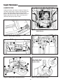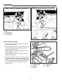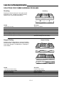
1
Print Vendor
Instructions
Paper Size:
How to use this file
Operator’s Manuals
• 11x17
• Body - 50 lbs brilliant white offset or equivalent
• Cover - on pre-printed two tone “Swash” stock.
Press:
• Body - 1 color, 2-sided
• Cover - 1 color, 1 sided
Bindery:
• Saddle stitch, face trim
*if too thick for saddle stitch, tape bind
Covers:
• FRONT COVER is present at the beginning of the file.
• BACK COVER is the page immediately after the front cover.
• The part number for this manual (typically a 172_____ number) is
located on the front cover.
• This file may contain several manuals which differ only by their covers.
See the part number at the bottom of the cover page. .
Body:
• The body for all manuals is identical regardless of the cover.
• Odd number pages are always right hand pages, even number pages
are always left hand pages.
General:
• This instruction sheet is NOT part of the manual and must not be
printed.
• Pages labeled “THIS PAGE INTENSIONALLY BLANK” are placement
pages and should NOT be printed.
THIS PAGE INTENTIONALLY BLANK
(FOR PLACEMENT ONLY - DO NOT PRINT)
OPERATOR’S
MANUAL
Coronet / 400 / 2400 Series
11HP Gear Riders
16HP Hydro Riders
Mfg. No.
1693303
1693309
1693315
1693319
1694187
Mfg. No.
1694115
1694117
1694189
Description
Coronet, 11HP Gear
Coronet, 11HP Gear (Export)
411G, 11HP Gear
2411G, 11HP Gear
2411G, 11HP Gear
13HP Hydro Riders
Mfg. No.
1693305
1693311
1693882
1693884
1694288
1694289
1694290
Description
Coronet, 13HP Hydro
Coronet, 13HP Hydro (Export)
413H, 13HP Hydro
2413H, 13HP Hydro
Coronet, 13HP Hydro
2413H, 13HP Hydro
413H, 13HP Hydro
14HP Hydro Riders
Mfg. No.
1693307
1693313
1693317
1693321
Description
Coronet, 16HP Hydro
416H, 16HP Hydro
2416H, 16HP Hydro
30” Mower Decks
Mfg. No.
1692543
1692544
1694053
Description
30” Mower Deck
30” Mower Deck
30” Mower Deck
34” Mower Decks
Mfg. No.
1692545
1693168
1692545
1692546
1694191
Description
34” Mower Deck
34” Mower Deck (Export)
34” Mower Deck
34” Mower Deck
34” Mower Deck
Description
Coronet, 14HP Hydro
Coronet, 14HP Hydro (Export)
414H, 14HP Hydro
2414H, 14HP Hydro
1719188-08
(Supercedes 1719190 & 1719189)
Rev 8/2002
TP 100-2164-08-CO-SMA
MANUFACTURING, INC.
500 N Spring Street / PO Box 997
Port Washington, WI 53074-0997
www.simplicitymfg.com
© Copyright 2001, Simplicity Manufacturing, Inc.
All Rights Reserved. Printed in USA.
Table of Contents
Identification Numbers & Safety Decals............2
Safety Rules & Information.................................3
Features & Controls ............................................6
Troubleshooting, Adjustments & Service .......19
Troubleshooting the Rider.....................................19
Troubleshooting the Mower ..................................20
Seat Adjustment....................................................21
Steering Gear Adjustment.....................................21
Steering Wheel Adjustment ..................................21
Brake Adjustment..................................................22
Blade Brake Adjustment .......................................22
Mower Adjustments ..............................................23
Battery Charging ...................................................25
Rider Drive Belt Replacement...............................26
Mower Belt Replacement ......................................26
Control Functions ....................................................6
Safety Interlock System ..........................................7
Operating the Rider .............................................8
General ...................................................................8
Checks Before Starting ...........................................8
Clutch/Brake Pedal Operation ................................9
Starting The Engine ................................................9
Selecting Ground & Engine Speed .......................10
Stopping the Rider ................................................10
Operating the Mower ............................................11
Pushing the Rider by Hand ..................................11
Mower Removal and Installation ...........................12
Storage .................................................................13
Specifications ....................................................27
Parts & Accessories..........................................28
Lawn Care & Mowing Information .............LC—1
Regular Maintenance ........................................14
Maintenance Schedule .........................................14
Checking Tire Pressures.......................................14
Raising the Seat Deck ..........................................15
Checking/Adding Fuel ...........................................15
Fuel Filter ..............................................................15
Oil & Filter Change................................................15
Check / Change Air FIlter......................................15
Replace Spark Plug ..............................................15
Lubrication ............................................................16
Battery Maintenance .............................................17
Checking Battery Fluid ..................................17
Cleaning the Battery and Cables ..................17
Servicing the Mower Blades .................................18
International Symbols ................................LC—8
Technical Manuals ......................................LC—8
NOTE: In this manual, “left” and “right” are referred to as
seen from the operating position.
WARNING
Engine exhaust from this product contains
chemicals known, in certain quantities, to cause
cancer, birth defects, or other reproductive harm.
1
Identification Numbers & Safety Decals
IDENTIFICATION TAG LOCATIONS
When contacting your Authorized
Dealer for replacement parts, service,
or information YOU MUST HAVE
THESE NUMBERS.
SA
MP
LE
Unit
Identification Tag
IDENTIFICATION NUMBERS
PRODUCT
•
•
REFERENCE
DATA
Model Description Name/Number
Record your model name/number, unit and mower deck
manufacturer numbers and engine serial number in the
space provided for easy reference.
•
Mower Deck
Identification Tag
The Unit I.D. tag is located on the left-side, of the
frame, as shown below.
The Mower Deck I.D. tag is also on the left side, on
top of the mower deck.
Unit MFG Number
Unit SERIAL Number
Mower Deck MFG Number
Mower Deck SERIAL Number
Dealer Name
Date Purchased
For location of Engine Serial Number, refer to the
Engine Owner’s Manual.
ENGINE REFERENCE DATA
Be sure to fill out and return the Warranty Registration
Card supplied with your unit.
SAFETY DECALS
Engine Make
Engine Model
Engine Type/Spec
Engine Code/Serial Number
This unit has been designed and manufactured to provide you with the safety and reliability you would expect
from an industry leader in outdoor power equipment
manufacturing.
We have placed several safety labels on the unit to
remind you of important operating information.
All DANGER, WARNING, CAUTION and instructional
messages on your rider and mower should be carefully
read and obeyed. Personal bodily injury can result when
these instructions are not followed. The information is for
your safety and it is important! The safety decals below
are on your rider and mower.
Decal - Danger
Part No. 1704276
If any of these decals are lost or damaged, replace them
at once. See your local dealer for replacements.
These labels are easily applied and will act as a constant
visual reminder to you, and others who may use the
equipment, to follow the safety instructions necessary for
safe, effective operation.
Decal - Operating Information
Part No. 1713490
2
Decal - Danger
Part No. 1704277
Safety Rules & Information
Read these safety rules and follow them closely. Failure to obey these rules could result in loss of control
of unit, severe personal injury or death to you, or bystanders, or damage to property or equipment.
This mowing deck is capable of amputating hands and feet and throwing objects.
The triangle
in text signifies important cautions or warnings which must be followed.
GENERAL OPERATION
• Read, understand, and follow all instructions in the
manual and on the unit before starting.
• Engine exhaust from this product contains chemicals
known, in certain quantities, to cause cancer, birth
defects, or other reproductive harm.
• Only allow responsible adults, who are familiar with
the instructions, to operate the unit (local regulations
can restrict operator age).
• Clear the area of objects such as rocks, toys, wire,
etc., which could be picked up and thrown by the
blade(s).
• Be sure the area is clear of other people before mowing. Stop unit if anyone enters the area.
• Never carry passengers.
• Do not mow in reverse unless absolutely necessary.
Always look down and behind before and while travelling in reverse.
• Be aware of the mower discharge direction and do
not point it at anyone. Do not operate the mower without either the entire grass catcher or the deflector in
place.
• Slow down before turning.
• Never leave a running unit unattended. Always disengage the PTO, set parking brake, stop engine, and
remove keys before dismounting.
• Turn off the PTO switch to disengage the blades
when not mowing.
• Stop engine before removing grass catcher or unclogging chute.
• Mow only in daylight or good artificial light.
• Do not operate the unit while under the influence of
alcohol or drugs.
• Watch for traffic when operating near or crossing
roadways.
• Use extra care when loading or unloading the unit
into a trailer or truck.
• Data indicates that operators, age 60 years and
above, are involved in a large percentage of riding
mower-related injuries. These operators should evaluate their ability to operate the riding mower safely
enough to protect themselves and others from injury.
• Keep in mind the operator is responsible for accidents
occurring to other people or property.
• All drivers should seek and obtain professional and
practical instruction.
• Always wear substantial footwear and trousers.
Never operate when barefoot or wearing sandals.
• Before using, always visually check that the blades
and blade hardware are present, intact, and secure.
Replace worn or damaged parts.
• Never operate the machine with defective guards, or
without safety protective devices in place.
• Disengage attachments before: refueling, removing
an attachment, making adjustments (unless the
adjustment can be made from the operator’s position).
• When the machine is parked, stored, or left unattended, lower the cutting means unless a positive
mechanical lock is used.
• Follow the manufacturer’s recommendation for wheel
weights or counterweights.
• Before leaving the operator’s position for any reason,
engage the parking brake, disengage the PTO, stop
the engine, and remove the key.
• To reduce fire hazard, keep the unit free of grass,
leaves, & excess oil. Do not stop or park over dry
leaves, grass, or combustible materials.
TRANSPORTING AND STORAGE
• Always follow the engine manual instructions for
storage preparations before storing the tractor for
both short and long term periods.
• Always follow the engine manual instructions for
proper start-up procedures when returning the unit to
service.
• Never store the unit or fuel container inside where
there is an open flame or pilot light, such as in a
water heater. Allow unit to cool before storing.
• When transporting the unit on an open trailer, make
sure it is facing forward, in the direction of travel. If
the unit is facing backwards, wind lift could damage
the hood.
• Always observe safe refueling and fuel handling practices when refueling the tractor after transportation or
storage.
• Never store the unit (with fuel) in an enclosed poorly
ventilated structure. Fuel vapors can travel to an
ignition source (such as a furnace, water heater, etc.)
and cause an explosion. Fuel vapor is also toxic to
humans and animals.
TP 600-2459-03-UV-SMA
3
Safety Rules and Information
SLOPE OPERATION
WARNING
Slopes are a major factor related to loss-of-control and tipover accidents, which can result in severe injury or death.
All slopes require extra caution. If you cannot back up the
slope or if you feel uneasy on it, do not operate on it.
Control of a ride-on machine sliding on a slope will not be
regained by the application of the brake. The main reasons for loss of control are: insufficient tire grip on the
ground, speed too fast, inadequate braking, the type of
machine is unsuitable for it’s task, lack of awareness of the
ground conditions, incorrect hitching and load distribution.
Never operate on slopes greater than 17.6 percent
(10°) which is a rise of 3-1/2 feet (106 cm) vertically in
20 feet (607 cm) horizontally.
When operating on slopes use additional wheel
weights or counterweights. See your dealer to
determine which weights are available and
appropriate for your unit.
Select slow ground speed before driving onto slope.
In addition to front and rear weights, use extra caution
when operating on slopes with rear-mounted grass
catcher.
Mow UP and DOWN the slope, never across the
face, use caution when changing directions and DO
NOT START OR STOP ON SLOPE.
Do
• See your authorized dealer for recommendations of
wheel weights or counterweights to improve stability.
• Mow up and down slopes, not across.
• Remove obstacles such as rocks, tree limbs, etc.
• Watch for holes, ruts, or bumps. Uneven terrain could
overturn the unit. Tall grass can hide obstacles.
• Use slow speed. Tires may lose traction on slopes
even through the brakes are functioning properly.
Choose a low gear so that you will not have to stop or
shift while on the slope.
• Use extra care with grass catchers or other attachments. These can change the stability of the unit.
• Keep all movement on the slopes slow and gradual.
Do not make sudden changes in speed or direction.
• Always keep unit in gear especially when traveling
downhill. When clutching, release clutch slowly.
Do Not
• Do not start or stop on a slope. If tires lose traction,
disengage the blade(s) and proceed slowly straight
down the slope.
• Do not turn on slopes unless necessary, and then,
turn slowly and gradually downhill, if possible.
• Do not mow near drop-offs, ditches, or embankments. The mower could suddenly turn over if a
wheel is over the edge of a cliff or ditch, or if an edge
caves in.
• Do not mow on wet grass. Reduced traction could
cause sliding.
• Do not try to stabilize the unit by putting your foot on
the ground.
• Do not use grass catchers on steep slopes.
• Do not mow slopes you cannot back up.
• Do not shift to neutral and coast down hill.
Children
Tragic accidents can occur if the operator is not alert to the
presence of children. Children are often attracted to the
unit and the mowing activity. Never assume that children
will remain where you last saw them.
• Keep children out of the mowing area and under the
watchful care of another responsible adult.
• Be alert and turn unit off if children enter the area.
• Before and during reverse operation, look behind and
down for small children.
• Never carry children. They may fall off and be seriously injured or interfere with safe unit operation.
• Never allow children to operate the unit.
• Use extra care when approaching blind corners,
shrubs, trees, or other objects that may obscure
vision.
EMISSIONS
TOWED EQUIPMENT
• Engine exhaust from this product contains chemicals
known, in certain quantities, to cause cancer, birth
defects, or other reproductive harm.
• Look for the relevant Emissions Durability Period and
Air Index information on the engine emissions label.
• Never allow children or others in or on towed equipment.
• Tow only with a machine that has a hitch designed
for towing. Do not attach towed equipment except at
the hitch point.
• Follow the manufacturer’s recommendations for
weight limit for towed equipment and towing on
slopes.
• On slopes, the weight of the towed equipment may
cause loss of traction and loss of control.
• Travel slowly and allow extra distance to stop.
• Do not shift to neutral and coast down hill.
4
Safety Rules and Information
SERVICE AND MAINTENANCE
• Grass catcher components are subject to wear, damage, and deterioration, which could expose moving
parts or allow objects to be thrown. Frequently check
components and replace with manufacturer’s recommended parts, when necessary.
• Mower blades are sharp and can cut. Wrap the
blade(s) or wear gloves, and use extra caution when
servicing them.
• Check brake operation frequently. Adjust and service
as required.
• Use only factory authorized replacement parts when
making repairs.
• Always comply with factory specifications on all settings and adjustments.
• Only authorized service locations should be utilized
for major service and repair requirements.
• Never attempt to make major repairs on this unit
unless you have been properly trained. Improper service procedures can result in hazardous operation,
equipment damage and voiding of manufacturer’s
warranty.
• On multiple blade mowers, take care as rotating one
blade can cause other blades to rotate.
• Do not change engine governor settings or overspeed the engine. Operating the engine at excessive
speed can increase the hazard of personal injury.
• Disengage drive attachments, stop the engine,
remove the key, and disconnect the spark plug
wire(s) before: clearing attachment blockages and
chutes, performing service work, striking an object, or
if the unit vibrates abnormally. After striking an
object, inspect the machine for damage and make
repairs before restarting and operating the equipment.
• Never place hands near the hydro pump cooling fan
when the tractor is running. Cooling fan is located on
top of the transaxle.
• Use extra care in handling gasoline and other fuels.
They are flammable and vapors are explosive.
a) Use only an approved container.
b) Never remove gas cap or add fuel with the
engine running. Allow engine to cool before
refueling. Do not smoke.
c) Never refuel the unit indoors.
• If fuel is spilled, do not attempt to start the engine but
move the machine away from the area of spillage and
avoid creating any source of ignition until fuel vapors
have dissipated.
• Replace all fuel tank caps and fuel container caps
securely.
• Never fill containers inside a vehicle or on a truck bed
with a plastic bed liner. Always place containers on
the ground away from your vehicle before filling.
• Remove gas-powered equipment from the truck or
trailer and refuel it on the ground. If this is not possible, then refuel such equipment on a trailer with a
portable container, rather than from a gasoline dispenser nozzle.
• Keep nozzle in contact with the rim of the fuel tank or
container opening at all times until fueling is complete. Do not use a nozzle lock-open device.
• If fuel is spilled on clothing, change clothing immediately.
• Maintain or replace safety and instruction labels as
necessary.
• Never run the unit in an enclosed area where carbon
monoxide fumes may collect.
• Keep nuts and bolts, especially blade attachment
bolts, tight and keep equipment in good condition.
• Never tamper with safety devices. Check their proper
operation regularly and make necessary repairs if
they are not functioning properly.
• Keep unit free of grass, leaves, or other debris buildup. Clean up oil or fuel spillage.
• Stop and inspect the equipment if you strike an
object. Repair, if necessary, before restarting.
• Never make adjustments or repairs with the engine
running unless specified otherwise in the engine manufacturer’s manual.
• Do not remove the fuel filter when the engine is hot
as spilled gasoline may ignite. Do not spread fuel line
clamps further than necessary. Ensure clamps grip
hoses firmly over the filter after installation.
• Do not use gasoline containing METHANOL, gasohol
containing more than 10% ETHANOL, gasoline additives, or white gas because engine/fuel system damage could result.
• If the fuel tank must be drained, it should be drained
outdoors.
• Replace faulty silencers/mufflers.
5
Features
& Controls
Please take a moment and familiarize yourself with
the name, location, and function of these controls
so that you will better understand the safety and
operating instructions provided in this manual.
Figure 1. Rider and Mower Features & Controls
A.
B.
C.
D.
E.
F.
Mower Lift Lever
Fuel Tank
Ignition Switch
Auto-Leveling Rod™
Mower Hitch
Mower Deflector
G.
H.
I.
J.
K.
L.
PTO (Electric Clutch) Switch
Ground Speed Control Lever
Clutch/Brake Pedal
Parking Brake Control Knob
Dial-A-Cut Control™
Seat Adjustment lever
M.
N.
O.
P.
Q.
Engine Throttle / Choke Lever
Seat Deck
Drawbar
Engine Muffler
Mower Levelling Nut.
CONTROL FUNCTIONS
The information below briefly describes the function of individual controls. Starting, stopping, driving, and mowing
require the combined use of several controls applied in specific sequences. To learn what combination and sequence
of controls to use for various tasks see the OPERATION section.
A. Mower Lift Lever
E. Mower Hitch
This raises the mower into the transport position.
Quick-hitch system allows easy removal and installation
of mower and attachments
B. Fuel Tank
F. Mower Deflector
A 2 gal. (7.6L) see-through tank for fuel level reading.
Starts and stops the engine.
Deflector is a necessary safety device to control objects
thrown from the deck. Never mow without deflector in
place.
D. Auto-Levelling Rod™
G. PTO (Electric Clutch) Switch
Allows mower hitch (E) to raise and lower around very
tight corners while mower remains level.
Controls electric clutch for attachments. Pull out to
engage PTO; push in to disengage PTO.
C. Ignition Switch
6
Features & Controls
H. Ground Speed Control Lever
SAFETY
INTERLOCK SYSTEM
Controls ground speed and forward/reverse motion.
Push forward to go forward; pull back to go in reverse.
On hydro models, ground speed is controlled by how far
lever is in forward or reverse position.
This unit is equipped with safety interlock switches and other
safety devices. These safety systems are present for your
safety, do not attempt to bypass safety switches, and never
tamper with safety devices. Check their operation regularly.
I. Clutch/Brake Pedal
Press down to disengage clutch and apply brake. For
parking brake, depress pedal fully and pull up on parking
brake control knob (J).
Operational SAFETY Checks
Your unit is equipped with a seat switch safety system.
Check the seat switch operation every fall and spring with the
following tests.
J. Parking Brake Control Knob
Test 1 — Engine should NOT crank if any of the
following conditions exist:
Engages parking brake. Depress clutch/brake pedal (I)
fully and pull up knob to engage parking brake. To disengage brake, depress pedal and push knob down.
• Transmission lever is OUT of Neutral, OR
• PTO switch is engaged (ON), OR
• Clutch/brake pedal is NOT fully depressed.
K. Dial-A-Cut Control™
Test 2 — Engine SHOULD crank if ALL of the
following conditions are met:
Adjusts height of mower cut.
• Transmission lever is IN neutral, AND
• PTO switch is NOT engaged, AND
• Clutch/brake pedal IS fully depressed.
L. Seat Adjustment Lever
Automotive-style lever to allow seat to slide forward and
backward.
Test 3 — Engine should SHUT OFF if any of the
following conditions exist:
• Operator rises off seat with transmission in gear (control
lever out of the neutral gate) AND clutch/brake pedal
NOT depressed, OR
• Operator rises off seat with clutch/brake pedal NOT fully
depressed (parking brake OFF), OR
• Operator rises off seat with PTO engaged.
NOTE: If operator returns to seat before engine stops, the
engine will re-start and electric PTO clutch will re-engage.
M. Engine Throttle/Choke Lever
Push forward to increase engine RPM. Push all the way
forward for choke position.
N. Seat Deck
Lightweight polymer-alloy deck lifts up for easy access to
engine compartment.
NOTE: Once the engine has stopped, PTO switch must be
turned off after operator returns to the seat in order to start
the engine.
O. Drawbar
For use with utility carts or rear-mounted attachments,
such as Twin Bag Grass Catcher.
Test 4 — Blade Brake Check
Mower blades and mower drive belt should come to a complete stop within five seconds after electric PTO switch is
turned off (or operator rises off seat). If mower drive belt does
not stop within five seconds, see your dealer.
P. Engine Muffler
Exhausts hot air to the right side away from the fuel tank.
Use caution around the heat shields and muffler until hot
surfaces cool after operation.
Test 5 — Neutral Safety Checks
Neutral Gate Check: The unit should NOT move when the
ground speed control lever is in the Neutral gate.
Q. Mower Levelling Nut
Return-To-Neutral: On hydrostatic models, the ground
speed control lever should return to the neutral gate when the
clutch/brake pedal is fully depressed.
Allows for the accurate side-to-side levelling of the
mower deck.
WARNING
If the unit does not pass a safety test, do not
operate it. See your authorized dealer. Under no
circumstance should you attempt to defeat the
purpose of the safety interlock system.
7
Operating
the Rider
GENERAL OPERATING SAFETY
WARNING
Before first time operation:
• Be sure to read all information in the Safety and
Operation sections before attempting to operate this
rider and mower.
Never allow passengers to ride on the unit.
Before leaving the operator’s position for any reason,
engage the parking brake, disengage the PTO, stop
the engine and remove the key.
• Become familiar with all of the controls and how to
stop the unit.
To reduce fire hazard, keep the engine, rider and
mower free of grass, leaves and excess grease. Do
not stop or park rider over dry leaves, grass or
combustible materials.
• Drive in an open area without mowing to become
accustomed to the unit.
Gasoline is highly flammable and must be handled
with care. Never fill the tank when the engine is still
hot from recent operation. Do not allow open flame,
smoking or matches in the area. Avoid over-filling and
wipe up any spills.
DANGER
OPERATING ON SLOPES
CAN BE DANGEROUS
Never operate on slopes greater than 30 percent
(16.7°) which is a rise of three feet vertically in 10
feet horizontally.
CHECKS BEFORE STARTING
• Check that crankcase is filled to full mark on dipstick.
See the engine Operator’s Manual for instructions
and oil recommendations.
Operate the rider at a slow ground speed when
driving onto slope.
• Make sure all nuts, bolts, screws and pins are in
place and tight.
When operating on slopes greater than 15 percent
(8.5°) but less than 30 percent use addition wheel
weights or counterweights.
• Adjust the seat position, and make certain you can
reach all controls from operator’s position.
In addition to counterweights, use extra caution
when operating on slopes with rear-mounted
grass catcher. Mow UP and DOWN the slope,
never across the face, use caution when
changing directions and DO NOT START OR
STOP ON SLOPE.
• Fill the gasoline tank with fresh gasoline. Refer to
engine manual for gasoline recommendations.
• Make certain proper wheel or counterweights are
installed if required, and use extra caution if you will
be operating the unit on sloping ground.
8
Operating the Rider
CLUTCH/BRAKE PEDAL OPERATION
HYDRO MODELS
1. See Figure 2. Depressing the pedal from position A to
B disengages the transmission drive and also returns
the transmission control lever to neutral (from forward
speeds). Fully depressing the pedal to position B
applies the rider brake.
2. Parking brake is applied at pedal position B when
parking brake control knob (C, Figure 2) is pulled up
with pedal fully depressed.
CLUTCH/BRAKE PEDAL OPERATION
GEAR MODELS
1. See Figure 2. Depressing the clutch pedal from position A to B activates neutral start circuit, disengages
the transmission drive belt and allows the gear lever
to be shifted.
Figure 2. Clutch/Brake Pedal
A. Brake Pedal (Disengaged)
B. Brake Pedal (Engaged)
C. Parking Brake Knob
2. Fully depressing the clutch/brake pedal from position
A to B applies the rider brake. Parking brake is
applied at position B when parking brake control knob
(C, Figure 2) is pulled up with pedal depressed.
STARTING THE ENGINE
*2394
1. Seat yourself on the rider seat in the operating position. Set the parking brake using the clutch/brake
pedal (D, Figure 3) and parking brake knob (B).
2. Push down on the PTO switch (G, Figure 1) to disengage the PTO and place the ground speed control
lever (C, Figure 3) in neutral.
3. For cold starts, set the engine throttle (M, Figure 1) to
the choke position. For warm starts, set engine throttle at 1/2 throttle position .
4. Turn the key (C, Figure 1) to start and release when
engine has started.
5. Move the engine throttle (M, Figure 1) to the slow
position. Warm up the engine by running it for at least
a minute before engaging the PTO or driving the rider.
Figure 3. Controls
A. Mower Lift Lever
B. Parking Brake Knob
C. Ground Speed Control Lever
D. Clutch/Brake Pedal
E. Dial-A-CutTM Control
WARNING
Make certain the area
of operation, and
especially the
direction of travel is
clear of objects,
people and animals.
Always look DOWN
AND BEHIND before
backing!
9
Operating the Rider
SELECTING GROUND
& ENGINE SPEED
*2394
On hydro models, ground speed is infinitely variable
according to how far the control lever (C, Figure 4) is
moved in the forward or reverse position.
On gear models, ground speed is selected by depressing the clutch/brake pedal (D, Figure 4) and moving the
control lever (C, Figure 4) to the appropriate gear selection. Most mowing is done in 3rd or 4th gear with engine
set at full speed. If the terrain is rough, hilly or sloping,
use first or second gear. If the grass is wet or over 3”
(76mm) high, use full engine speed (with low gear) so
the mower will have enough power to cut the grass.
1. If you are ready to mow, lower the mower from the
transport position using lever (A, Figure 4) and set
the mowing height using the Dial-A-CutTM Control (E,
Figure 4).
2. Set the engine throttle (M, Figure 1) for full speed.
3. Use the PTO switch (G, Figure 1) to engage the
PTO.
4. Release the parking brake by depressing the
clutch/brake pedal (D, Figure 4) and pushing knob (B,
Figure 4) down.
5. On hydro models, move the ground speed control
lever (C, Figure 4) to the desired direction and speed
of travel to set the rider in motion.
On gear models, depress clutch/brake pedal, use
the ground speed control lever to select the proper
gear for conditions, then slowly release clutch/brake
pedal to set the rider in motion.
6. Adjust engine throttle (M, Figure 1) to the desired
speed. Full throttle is recommended for mowing.
Figure 4. Controls
A. Mower Lift Lever
D. Clutch/Brake Pedal
B. Parking Brake Knob
E. Dial-A-CutTM Control
C. Ground Speed Control Lever
STOPPING THE RIDER
1. On hydro models, move the ground speed control
lever (C, Figure 4) into the NEUTRAL position to
make a gradual stop. To make a more rapid stop,
depress the clutch/brake pedal (D, Figure 4).
NOTE: On hydro models, the ground speed control
lever will return to neutral from forward automatically
when the clutch/brake pedal is depressed.
WARNING
2.
Make certain the area
of operation, and
especially the
direction of travel is
clear of objects,
people and animals.
3.
4.
Always look DOWN
AND BEHIND before
backing!
5.
10
On gear models, press the clutch/brake pedal (D,
Figure 4) down only far enough to disengage the
clutch to make a gradual stop. For a more rapid stop,
press pedal down farther to apply the brake. Move
the ground speed control lever to NEUTRAL before
releasing the pedal.
Engage the parking brake by fully depressing
clutch/brake pedal and pulling up on parking brake
knob (B, Figure 4).
Use the PTO switch (G, Figure 1) to disengage the
PTO.
Set the engine throttle (M, Figure 1) to 1/2 throttle
setting and allow the engine to idle for 20 seconds.
Stopping a hot engine too fast may cause engine
damage.
Turn key (C, Figure 1) to OFF and remove it.
Operating the Rider
WARNING
Make certain
direction of travel is
clear of objects,
people and animals.
Always look DOWN
AND BEHIND before
backing!
OPERATING THE MOWER
1. When traveling to or from the work site, fully raise the
mower using the mower lift lever (A, Figure 4). At the
work site, lower mower using the lift lever.
2. Use the Dial-A-CutTM control (E, Figure 4) to adjust
the height of the mower. Pull back slightly on mower
lift lever (A, Figure 4) to relieve pressure and turn
clockwise to raise mower cutting height, or counterclockwise to lower cutting height.
NOTE: Cutting height scale is located on the quadrant at
base of lift lever. Scale is numbered 1 thru 4, with 4 representing the highest cutting height.
*2392
Figure 5. Mower Belt Pattern
A. PTO Pulley
D. Front Idler Pulley (30”)
B. Arbor Pulley (30”)
Left Arbor Pulley (34”)
Right Arbor Pulley (34”)
C. Idler Pulley
E. Idler Pulley Arm
PUSHING THE RIDER BY HAND
*2511
Hydro Models
1. Engine should be off and ignition key removed.
2. Place the mower in the transport position (up) using
the mower lift lever (A, Figure 4).
3. See Figure 6—To push the rider by hand, the
release lever must be placed in the PUSH position.
4. To drive the rider, release lever must be moved to the
DRIVE position.
Move forward for drive
position, pull rearward
for push position.
Gear Model
1. Engine should be off and ignition key removed.
2. Place the mower in the transport position (up) using
the mower lift lever (A, Figure 4).
3. Depress the clutch/brake pedal and place the ground
speed control lever (C, Figure 4) in the neutral gate.
4. Unlock the parking brake.
Forward
Figure 6. Transaxle Release Lever - Hydro Models
DO NOT TOW RIDER
Towing the unit will cause transmission
damage. Do not use another vehicle to
push or pull this unit.
11
Operating the Rider
*2396
Figure 7. Mower Removal/Installation (34” mower shown)
A. Idler Pulley Arm
D.
B. Idler Pulley
E.
C. PTO (Electric Clutch) Pulley
F.
Lift Cable
Lift Hook
Rear Trailing Arms
WARNING
Stop engine and remove key. Do not engage PTO
until mower is completely removed or installed and
operator is seated.
MOWER REMOVAL AND INSTALLATION
NOTE: Perform mower installation on a hard, level surface such as a concrete floor. For easier mower removal
and installation, rear trailing arms (F, Figure 7) can be
removed by removing spring clips and clevis pins.
*2390
Figure 8. Mower Hitch
A. Lever
B. Mower Hitch
1. Park rider and turn off PTO switch and engine,
remove the key and apply parking brake. Turn the
wheels fully to the left.
2. On left-hand side of 34” mower, push idler pulley arm
(A, Figure 7) to relieve belt tension.
C. Rider Hitch Brackets
5. Remove mower hitch (B, Figure 8) from rider hitch
brackets (C) by pulling spring-loaded lever (A) forward and lifting up on hitch. Place mower hitch on
ground.
On right-hand side of 30” mower, pull idler pulley arm
to relieve belt tension.
6. With wheels turned fully left, remove mower from
underneath right-hand side of rider.
3. With belt tension relieved, remove belt from idler pulley (B, Figure 7) and PTO pulley (C). Removing belt
relieves tension on the front hitch assembly.
7. To install mower, reverse above steps. Check mower
belt pattern (as shown in Figure 5 on page 11). Make
sure that the mower lift cable is installed with hook
toward the rear (see Figure 7 inset) and rear trailing
arms (F, Figure 7) are positioned above rear torsion
bar.
Dial-A-CutTM control
set to
4. With lift lever down and
the lowest setting, remove lift cable (D, Figure 7) from
mower hook (see inset illustration, Figure 7).
NOTE: Pull back slightly on the lift lever to allow easier
turning of the Dial-A-CutTM control.
12
Operating the Rider
STORAGE
WARNING
• Battery life will be increased if it is removed, put in a
cool, dry place and fully charged about once a month.
If the battery is left in the unit, disconnect the negative cable.
Never store the unit (with fuel) in an enclosed,
poorly ventilated structure. Fuel vapors can
travel to an ignition source (such as a furnace,
water heater, etc.) and cause an explosion.
Before starting the unit after it has been stored:
• Check all fluid levels. Check all maintenance items.
Fuel vapor is also toxic to humans and animals.
• Perform all recommended check and procedures
found in the engine owner’s manual.
Before you store your unit for the off-season, read the
Maintenance and Storage instructions in the Safety
Rules section, then perform the following steps:
• Allow the engine to warm up for several minutes
before use.
• Disengage the PTO, set the parking brake, & remove
the key.
• Perform engine maintenance and storage measures
listed in the engine owner’s manual. This includes
draining the fuel system, or adding stabilizer to the
fuel (do not store a fueled unit in an enclosed structure - see above).
13
Regular
Maintenance
MAINTENANCE SCHEDULE & PROCEDURES
The following schedule should be followed for normal care of your rider and mower. You will need to keep a record of
your operating time. Determining operating time is easily accomplished by multiplying the time it takes to do one job
by the number of times you’ve done the job, or you can install the optional hour meter.
See
Page
SAFETY ITEMS
Before
Before
First Use Each Use
Every
5 Hours
Every
25 Hours
Every
100 Hours
Spring
& Fall
Check Safety Interlock System
7
●
●
Check Rider Brakes
22
●
●
Check Mower Blade Stopping Time
NORMAL CARE ITEMS
7 & 22
See
Page
●
Before
Before
First Use Each Use
Every
5 Hours
Every
25 Hours
●
Every
100 Hours
Check Rider/Mower for loose hardware
—
●
●
●
Check Engine Oil Level
15*
●
●
●
Check Engine Air Filter
15*
●
*
●
Lubricate Rider & Mower
16
●
***●
Check Tire Pressure
14
●
***●
Check Transmission Fluid (Hydro Only)****
—
●
Check Fuel Filter
15
●
●
Clean Battery & Cables
17
●
●
Clean & Sharpen Mower Blades
18
●
●
Change Engine Oil & Filter **
*
**
***
****
●
***●
***● Every 50 Hours
CHECK TIRE PRESSURES
Tire Pressure should be checked periodically, and maintained at the levels shown in the chart. Note that these
pressures may differ slightly from the “Max Inflation”
stamped on the side-wall of the tires. The pressures
shown provide proper traction, improve cut quality, and
extend tire life.
Pressure
Front
20 psi (138 kPa)
Rear
10 psi (69 kPa)
Figure 9. Checking Tire Pressure
14
***●
Only if transmission is serviced.
See the engine manufacturer's owner's manual.
Change original engine oil after first 5 hours of operation.
More often in hot (over 85° F: 30° C) weather or dusty operating conditions.
Transmission is a sealed unit and requires no regular interval fluid changes.
Tire
Spring
& Fall
Regular Maintenance
C
B
D
A
E
Figure 10. Engine Compartment
A. Fuel Tank
B. Ignition Switch
C. Battery
D. Throttle / Choke Cable
E. PTO Switch (Electric Clutch)
F. Air Filter
G. Oil Fill / Dipstick
H. Oil Drain
I. Fuel Filter (In-line, Not Shown)
F
G
H
RAISING THE SEAT DECK
To gain access to the engine compartment, simply tilt the
seat deck forward.
CHECKING/ADDING FUEL
Do not use gasoline containing METHANOL,
gasohol containing more than 10% ethanol,
gasoline additives, premium gasoline, or
white gas because engine/fuel system
damage could result.
Check the gas tank (A, Figure 10) to be sure there is
enough gasoline to complete the job. To add gasoline,
remove the gas cap. Do not overfill. Leave room in the
tank for fuel expansion. Refer to your engine manual for
gasoline recommendations. Install and hand tighten the
gas cap.
WARNING
FUEL FILTER
The fuel filter is located in fuel line between fuel tank and
carburetor. If filter is dirty or clogged, replace as follows.
Place a container below filter to catch spilled gasoline.
1. Using a pliers, open and slide hose clamps from fuel
filter.
2. Remove hoses from filter.
3. Install new filter in proper flow direction in fuel line.
Secure with hose clamps. See warning at beginning
of procedure.
Gasoline is highly flammable and must be
handled with care. Never fill the tank when the
engine is still hot from recent operation. Do not
allow open flame, smoking or matches in the
area. Avoid over-filling and wipe up any spills.
Do not remove fuel filter when engine is hot, as
spilled gasoline may ignite. DO NOT spread hose
clamps further than necessary. Ensure clamps
grip hoses firmly over filter after installation.
OIL & FILTER CHANGE
Refer to engine owners manual.
CHECK / CHANGE AIR FILTER
Refer to engine owners manual.
REPLACE SPARK PLUG
Refer to engine owners manual.
15
Regular Maintenance
LUBRICATION
Lubricate the rider and mower as shown in Figures 11 16. When a grease gun is shown, wipe the fitting clean,
apply two or three shots of lithium base automotive
grease, and wipe off excess grease. When an oil can is
shown, wipe the area clean, apply a few drops of oil
(SAE 30), then wipe up drips or spills.
*2388B
*2402
Figure 14. Rider Lubrication Points - Rear Half (Gear
Model Shown)
Figure 11. Brake Pedal Pivot Point
*2390
Figure 12. Front Axle Lubrication Points
Figure 15. Rider Lubrication Points - Front Half
*2397
Note: On 30” mower,
grease fitting is on
topside of deck.
Figure 13. Mower Deck Lubrication Points
Figure 16. Arbor Lubrication Points
16
Regular Maintenance
WARNING
B
Be careful when handling the battery. Avoid spilling
electrolyte. Keep flames and sparks away from the
battery.
A
When removing or installing battery cables, disconnect
the negative cable FIRST and reconnect it LAST. If not
done in this order, the positive terminal can be shorted
to the frame by a tool.
BATTERY MAINTENANCE
Checking the Battery Fluid
1. Raise the seat deck.
2. Remove battery filler cap (A, Figure 17). Fluid must be
even with the bottom of ring (B). If not, add distilled
water.
3. Reinstall filler cap.
Figure 17. Battery Fluid Check
A. Battery Cap
B. Bottom of Split Ring
Cleaning the Battery and Cables
1. Disconnect the cables from the battery, negative
cable first (B, Figure 18).
2. Remove the battery and clean the compartment with
a solution of baking soda and water.
3. Clean the battery terminals and cable ends with a
wire brush until shiny.
4. Reinstall the battery and reattach the battery cables,
positive cable first (see A, Figure 18).
5. Coat the cable ends and battery terminals with petroleum jelly or non-conducting grease.
Figure 18. Battery
A. Positive Battery Terminal
B. Negative Battery Terminal
C. Vent Tube
D. Holddown Strap
17
Regular Maintenance
SERVICING THE MOWER BLADES
WARNING
For your personal safety, do not handle the sharp
mower blades with bare hands. Careless or improper
handling of blades may result in serious injury.
1. Remove mower from the rider.
2. Blades should be sharp and free of nicks and dents.
If not, sharpen blades as described in following steps.
3. To remove blade for sharpening, use wooden block
to hold blade while removing the blade mounting capscrew (Figure 19).
LOOSEN
Figure 19. Removing The Blade
4. Use a file to sharpen blade to fine edge. Remove all
nicks and dents in blade edge. If blade is severely
damaged, it should be replaced.
5. Balance the blade as shown in Figure 20. Center the
blade’s hole on a nail lubricated with a drop of oil. A
balanced blade will remain level.
6.Reinstall each blade with the tabs pointing up toward
deck as shown in Figure 21. Secure with a capscrew
(D), cup washer (C) and hex washer (B). Use a
wooden block to prevent blade rotation and torque
capscrews to 45-55 ft.lbs. (61-75 N.m.).
Figure 20 Balancing The Blade
WARNING
B
For your personal safety, blade mounting capscrews
must each be installed with a hex washer and spring
washer, then securely tightened. Torque blade
mounting capscrew to 45-55 ft. lbs. (61-75 N.m.)
C
D
A
Torque to
TIGHTEN
45-55 ft.lbs
Figure 21. Installing The Blade
A. Wooden Block
C. Cup Washer
B. Hex Washer
D. Capscrew
18
Troubleshooting
Adjustments & Service
TROUBLESHOOTING
WARNING
While normal care and regular maintenance will extend
the life of your equipment, prolonged or constant use
may eventually require that service be performed to
allow it to continue operating properly.
To avoid serious injury, perform maintenance on the
tractor or mower only when the engine is stopped and
the parking brake engaged.
The troubleshooting guide below lists the most common
problems, their causes and remedies.
Always remove the ignition key, disconnect the spark
plug wire and fasten it away from the plug before
beginning the maintenance, to prevent accidental
starting of the engine.
See the information on the following pages for instructions on how to perform most of these minor adjustments
and service repairs yourself. If you prefer, all of these
procedures can be performed for you by your local
authorized dealer.
TROUBLESHOOTING THE RIDER
PROBLEM
CAUSE
REMEDY
Engine will not turnover or start.
1. Ground speed control lever
not in neutral-start position.
2. PTO (electric clutch) switch
in ON position.
3. Out of fuel.
1. Shift into neutral.
4. Engine flooded.
5. Circuit breaker tripped.
6. Battery terminals require cleaning.
7. Battery discharged or dead.
8. Wiring loose or broken.
Engine starts hard or runs poorly.
Engine knocks.
Excessive oil consumption.
Engine exhaust is black.
2. Place in OFF position.
3. If engine is hot, allow it to cool, then refill the
fuel tank.
4. Move throttle control out of CHOKE position .
5. Wait one minute for automatic reset. Replace
if defective (see your dealer).
6. See Normal Care section.
7. Recharge or replace.
8. Visually check wiring & replace broken or
frayed wires. Tighten loose connections.
9. Repair or replace.
10. Replace if needed (see your dealer.)
11. Clean and gap or replace.
See engine manual.
12. Drain fuel & refill with fresh fuel.
13. Drain fuel & replace with fresh fuel.
9. Solenoid or starter motor faulty.
10. Safety interlock switch faulty.
11. Spark plug(s) faulty, fouled or
incorrectly gapped.
12. Water in fuel.
13. Old stale gas.
14. Clutch/brake pedal not depressed.
1. Fuel mixture too rich.
1. Move the throttle control out of the CHOKE
position. If problem persists, clean the air filter.
(See engine manual.)
2. Carburetor adjusted incorrectly.
2. See engine manual.
3. Spark plug(s) faulty, fouled, or
3. Clean & gap or replace. See engine manual.
incorrectly gapped.
1. Low oil level.
1. Check/add oil as required.
2. Using wrong grade oil.
2. See engine manual.
1. Engine running too hot.
1. Clean engine fins, blower screen and air
cleaner.
2. Using wrong weight oil.
2. See engine manual.
3. Too much oil in crankcase.
3. Drain excessive oil.
1. Dirty air filter.
1. Clean air filter. See engine manual.
2. Choke not fully open.
2. Move throttle control out of CHOKE position.
If problem persists, check air filter and
carburetor adjustments. See engine manual.
19
Troubleshooting, Adjustment & Service
TROUBLESHOOTING THE RIDER (CONTINUED)
PROBLEM
CAUSE
Engine runs, but rider will not drive.
Rider drive belt slips.
Brake will not hold.
Rider steers hard or handles poorly.
REMEDY
1. Ground speed control lever in
neutral.
2. (Hydro models only) Transmission
release lever in “push” position.
3. Belt is broken.
4. Drive belt slips.
5. Brake is not fully released.
1. Clutch is out of adjustment.
2. Pulleys or belt greasy or oily.
3. Belt stretched or worn.
4. Idler pulley pivot bracket “frozen”
in declutched position.
1. Brake is incorrectly adjusted.
2. Internal brake disc on
transaxle worn.
1. Steering linkage is loose.
2. Improper tire inflation.
3. Spindle bearings dry.
TROUBLESHOOTING THE MOWER
1. Shift in forward or reverse.
2. Move into drive position.
3. See Drive Belt Replacement.
4. See problem and cause below.
5. See Brake Adjustment.
1. See your dealer.
2. Clean as required.
3. Replace with correct belt.
4. Remove idler pulley, clean and lubricate.
1. See Brake Adjustment.
2. See your dealer.
1. Check and tighten any loose connections. See
Steering Gear Adjustment.
2. Check and correct.
3. Grease spindles. See Lubricating the rider.
PROBLEM
CAUSE
REMEDY
Mower will not raise.
1. Lift cable not properly attached or
damaged.
1. Mower not leveled properly.
2. Rider tires not inflated equally
or properly.
1. Engine speed too slow.
2. Ground speed too fast.
1. Attach or repair.
Mower cut is uneven.
Mower cut is rough looking.
1. See Mower Adjustment.
2. See Normal Care.
1. Set to full speed.
2. Set ground speed control lever at a slower
ground speed.
3. Blades dull and require sharpening. 3. See Servicing the Mower Blades.
4. Mower drive belt slipping.
4. Belt oily or worn. Clean or replace belt as
necessary.
5. Check PTO (Electric Clutch)
5. Clutch may need to be adjusted.
Adjustment.
6. Blades not properly fastened
6. See Servicing the Mower Blades.
to arbors.
Engine stalls easily with
1. Engine speed too slow.
1. Set for 3/4 to full throttle.
mower engaged.
2. Ground speed too fast.
2. Reduce ground speed.
3. Carburetor not adjusted properly.
3. Adjust carburetor (See engine owners
manual.)
4. Cutting height set too low when
4. Cut tall grass at maximum cutting height
mowing tall grass.
during first pass.
5. Discharge chute jamming with
5. Cut grass with discharge pointing toward
cut grass.
previously cut area.
Excessive mower vibration.
1. Blade mounting screws are loose.
1. Tighten to 45-55 ft.lbs. (61-75 N.m.).
2. Mower blade(s), arbors, or pulleys
2. Check and replace as necessary.
are bent.
3. Mower blade(s) out of balance.
3. Remove, sharpen and balance blade(s).
See Servicing the Mower Blade(s).
4. Belt installed incorrectly.
4. See Belt Replacement.
Excessive belt breakage.
1. Bent or rough pulleys.
1. Repair or replace.
2. Using incorrect belt.
2. See your dealer.
Mower drive belt slips or fails to drive. 1. Idler pulley spring broken or not
1. See your dealer.
properly attached.
2. Mower drive belt broken.
2. Replace.
20
Troubleshooting, Adjustment & Service
SEAT ADJUSTMENT
WARNING
Use the lever on the front of the seat (See L, Figure 1 on
page 6) to adjust the seat forward or rearward for best
rider comfort.
To avoid serious injury, perform adjustments only
with engine stopped, key removed and rider on
level ground.
STEERING GEAR ADJUSTMENT
*2401
Capscrews
If there is excessive slack in the steering system, the
steering gear can be reindexed to the steering shaft.
1. See Figure 22. Loosen the two capscrews (A) and
push bracket so that gear teeth are closely meshed.
2. Tighten nuts after adjustment.
Figure 22. Steering Gear Adjustment
A. Capscrews
STEERING WHEEL ADJUSTMENT
A
Your unit is equipped with a dual position steering shaft
to allow for steering wheel adjustment for rider comfort.
1. Pull down on the rubber boot to expose the two holes
in the steering shaft (A, Figure 23).
2. Use a suitable drift to remove the roll pin at the base
of the steering wheel.
3. Align the hole in the steering wheel with the appropriate steering shaft hole and install the roll pin.
NOTE: Steering wheel is factory installed with the roll pin
in the bottom hole.
Figure 23. Steering Wheel Height Adjustment
A. Steering Shaft
21
Adjustments
BRAKE ADJUSTMENT
2 9/16" – 2 5/8"
Brake Adjustment - Gear Models
1. Place the transmission in gear and release the parking brake.
2. Move the brake lever (B) forward. There should be a
1/8" gap between the lever (B) and the stop (C) as
shown in Figure 24.
3. To adjust clearance, turn nut (D) clockwise to
decrease the gap or turn nut counterclockwise to
increase the gap.
4. Set the parking brake. Loosen or tighten adjustment
nut (E) to achieve a 2 9/16"–2 5/8" compressed
spring length as shown in Figure 24.
E
*2393
Figure 24. Brake Adjustment (Gear Model)
A. Compressed Spring D. Nut
B. Brake Lever
E. Adjustment Nut
C. Stop
Brake Adjustment - Hydro Models
1. Release the parking brake.
2. Place a .025" feeler gauge (A, Figure 25) between
the two outer brake stators (refer to inset illustration).
The gap should be between .025"–.030". To adjust:
a. Remove cotter pin from castellated nut if present.
b. To decrease gap, hold feeler gauge in gap and turn
nut (B) clockwise until resistance is felt on the feeler gauge. To increase gap, turn nut (B) counterclockwise and recheck gap.
c. If cotter pin was removed, back off nut (counterclockwise) until the nearest slot is aligned with hole
in threads. Replace cotter pin.
3. Set the parking brake. Loosen or tighten adjustment
nut (C) to achieve a 2 11/16"–2 13/32" compressed
spring length as shown in Figure 25.
4. Lubricate the stators with spray lubricant (see Figure
25).
Spray Lubricant Here
BLADE BRAKE ADJUSTMENT
Mower blades and mower drive belt should come to a
complete stop within five seconds after electric PTO
switch is turned off.
1. With rider in neutral, PTO disengaged and operator in
seat, start the rider engine.
2. Look over the left-hand footrest at the mower drive
belt. Engage the PTO and wait several seconds.
Disengage the PTO and check the amount of time it
takes for the mower drive belt to stop.
3. If mower drive belt does not stop within five seconds,
see your dealer.
Figure 25. Brake Adjustment (Hydro Model)
A. Feeler Gauge
C. Adjustment Nut
B. Nut
22
Adjustments
MOWER ADJUSTMENTS
WARNING
If the cut is uneven, the mower may need leveling.
Unequal or improper tire pressure may also cause an
uneven cut. Make sure tire pressure is correct as specified in Checking Tire Pressure. To achieve proper mower
levelling, perform Side-To-Side Leveling, Front-To-Back
Leveling and Transport Height Adjustment procedures, in
order, as follows.
Before checking mower, shut off PTO and engine.
Allow all moving parts to stop. Remove ignition key,
then disconnect the spark plug wire and fasten it
away from the spark plug.
*2397
Side-To-Side Leveling
1. With the mower installed, place the rider on a
smooth, level surface such as a concrete floor. Turn
the front wheels straight forward.
2. Check for bent blades and replace if necessary.
3. Loosen nut (C, Figure 26) so trailing arms are loose.
Mower must be resting on rollers with no weight on
trailing arms.
4. Use the Dial-A-CutTM Control (E, Figure 27) and
place mower in mid-cut position by aligning front
edge of mower lift lever (A) with number 2 or 3 on
quadrant scale. Make sure mower lift lever is in down
position.
5. Make sure rear rollers (C, Figure 28) are on the
ground. If not, refer to Transport Height Adjustment.
Figure 26. Trailing Arms
A. Spacers
B. Rear Mower Rollers
NOTE: If rollers do not rest on the ground and it is
necessary to perform transport height adjustment, it
is necessary to perform transport height adjustment
again after all leveling procedures are completed.
C. Nut
D. Rear Trailing Arms
WARNING
6. Position blade(s) side-to-side and measure distance
form outside tip of blade(s) to ground. Measurement
should be equal (within 1/8”).
Mower blades are sharp. Turn the mower drive belt
to rotate blades into position or wear protective
gloves to protect against injury.
7. See Figure 28. On left side of mower, make sure
eccentric nut is in correct position as shown. Loosen
outside nut (A) and rotate eccentric nut (B) so that flat
side with hole closest to it is towards the rear. Tighten
outside nut (A) while holding eccentric nut (B).
*2394
F
8. On right side of mower, loosen outside nut (A). Turn
eccentric nut (B) counterclockwise to raise side of
mower, or clockwise to lower right hand side of
mower.
NOTE: Do not turn eccentric nut more than 1/4 turn in
either direction. When adjusted beyond 1/4 turn, nut will
move mower in opposite direction than when starting
adjustment.
9. When adjustment is correct, hold eccentric nut (B)
and tighten nut (A) to 30 ft. lbs. Check measurement
on both sides of mower.
Figure 27. Dash Controls (shown with steering wheel
removed)
A. Mower Lift Lever
D. Clutch/Brake Pedal
B. Parking Brake Knob E. Dial-A-CutTM Control
C. Ground Speed Lever F. Steering Shaft
23
Adjustments
*2399
Figure 28. Leveling The Mower Side-to-Side
A. Nut
B. Eccentric Nut
C. Rear Rollers
Front-To-Back Leveling
*2397
1. Make sure mower is level side-to-side and that rear
rollers are on the ground.
2. Position blade(s) front-to-back. Measure the distance
from the ground to front tip of blade(s), and from
ground to rear tip of blade(s).
On 30” mower, the front tip should be level to 1/8”
(3 mm) higher than rear tip.
On 34” mower, the front tips should be 1/4” (6 mm)
higher than the rear tips.
3. See Figure 29. Loosen jam nut (E). To lower rear of
mower deck, loosen nut (B) which will lengthen leveling rod (D). To raise rear of deck, shorten leveling rod
(D). When proper measurement is obtained, tighten
nut (A) against bracket, then tighten jam nut (E)
against nut (A).
Figure 29. Front-To-Back Levelling
A. Adjustment Nut
D. Levelling Rod
B. Rear Nut
E. Jam Nut
C. Bracket
24
Adjustments
Transport Height Adjustment
Transport height should be adjusted so that rear mower
rollers are 1/8” - 1/4” (3-6 m) above ground when mower
lift lever is in transport position. To adjust, perform both
mower leveling procedures first, then do the following
procedure.
See Figure 30.
1. Park rider on a flat level surface.
2. Adjust Dial-A-CutTM control so that front edge of
mower lift lever is aligned with 2-3/4” mark (34”
mower) or at 3” mark (30” mower) on the quadrant
scale.
3. Loosen nut (C) and position spacer (A) against rear
trailing arms (D). Position both the left and right side
spacers against trailing arms.
4. Tighten nut (C) securely.
5. Place mower lift lever in transport position. Rear
mower rollers should be 1/8” - 1/4” off ground. If not,
repeat steps 2 - 4.
*2397
Figure 30. Transport Height Adjustment
A. Spacers
C. Nut
B. Rear Mower Rollers D. Rear Trailing Arms
BATTERY CHARGING
WARNING
Keep open flames and sparks away from the
battery; the gasses coming from it are highly
explosive. Ventilate the battery well during
charging.
A dead battery or one too weak to start the engine may
be the result of a defect in the charging system or other
electrical component. If there is any doubt about the
cause of the problem, see your dealer. If you need to
replace the battery, follow the steps under Cleaning the
Battery & Cables in the Regular Maintenance Section.
To charge the battery, follow the instructions provided by
the battery charger manufacturer as well as all warnings
included in the safety rules sections of this book. Charge
the battery until fully charged (until the specific gravity of
the electrolyte is 1.250 or higher and the electrolyte temperature is at least 60° F). Do not charge at a rate higher than 10 amps.
25
Belt Replacement
*2391
To avoid damaging belts, DO NOT PRY
BELTS OVER PULLEYS.
RIDER DRIVE BELT
Replacement of the rider drive belt requires removal of
the transmission and carrier frame. Should the drive belt
ever fail, contact your dealer for replacement.
MOWER BELT - 30”
See Figure 31.
Figure 31. Belt Pattern - 30” Mower
A. Idler Pulley Arm
D. Front Idler Pulley
B. Idler Pulley
E. PTO Pulley
C. Center Arbor Pulley
(Electric Clutch)
1. Mower does not need to be removed to install a new
belt. However, for easier access, mower can be
removed following steps in “Mower Removal and
Installation.
2. If mower is not removed, place mower in lowest cutting position. Pull idler pulley arm (A) towards you to
relieve belt tension. Remove belt from idler pulley (B)
and center arbor pulley (C).
3. Remove belt from front idler pulley (D) and PTO pulley (E).
4. Replace old belt with new belt. Make sure V-side of
belt runs in all pulley grooves except for idler pulley
(B). Check belt pattern as shown.
5. Install mower if it was removed, and install belt on
PTO pulley (E).
MOWER BELT - 34”
See Figure 32.
1. Mower does not need to be removed to install a new
belt. However, for easier access, mower can be
removed following steps in “Mower Removal and
Installation.
Figure 32. Mower Belt Replacement - 34”
A. Idler Pulley Arm
D. Capscrews
B. Idler Pulley
E. Arbor Cover
C. PTO Pulley
2. If mower is not removed, place mower in lowest cutting position. Push idler pulley arm (A, Figure 31)
away from you to relieve belt tension. Remove belt
from idler pulley (B) and PTO pulley (C).
3. Remove the three capscrews (D, Figure 31) securing
the left-hand arbor cover.
4. Remove old belt from arbor pulleys and replace with
new belt. Make sure V-side of belt runs in all arbor
pulley grooves and flat side of belt runs against idler
pulley. See Figure 33 for belt pattern
5. Install mower if it was removed, and install belt to
PTO pulley (C, Figure 32). Push idler arm and install
belt around idler pulley.
*2392
Figure 33. Belt Pattern - 34” Mower
A. Idler Arm Pulley
D. Right Arbor Pulley
B. Idler Pulley
E. Left Arbor Pulley
C. PTO Pulley
26
Specifications
NOTE: Specifications are correct at time of printing and are subject to change without notice.
ENGINE
CHASSIS
11 HP I/C — Briggs & Stratton
Front Wheels
Horsepower
Displacement
Electrical
Oil Capacity
10.5 HP @ 3600 rpm
28.4 Cu. In. (465 cc)
12 Volt, 3 Amp D.C. Battery: 200 CCA
3 Pints (1.42 L)
Rear Wheels
Fuel Tank
13 HP Diamond OHV — Briggs & Stratton
Horsepower
Displacement
Electrical
Air Cleaner
Oil Capacity
Turning Radius
13 HP @ 3600 rpm
28.4 Cu. In. (465 cc)
12 Volt, 3 Amp D.C. Battery 200 CCA
Pre-Cleaned Air to Paper Filter
3 Pints (1.42 L)
DIMENSIONS
Overall Length
61 In. (155 cm)
Overall Width
- w/30 mower
38.5 In. (97.8 cm)
- w/34 mower
45.5 In. (115.6 cm)
- at rear wheels
33 In. (83.8 cm)
Height at
- steering wheel
41 In. (104.1 cm)
- seat back
35 In. (88.9 cm)
- engine cover
28 In. (71.1 cm)
Wheel Base
43 In. (109.2 cm)
Weight (apx.)
- 8.5 HP w/30”mower
Net: 405 lbs. (183 kg)
- 12 HP w/30”mower
Net: 405 lbs. (183 kg)
- 12 HP w/34”mower
Net: 405 lbs. (183 kg)
- 13 HP w/34”mower
Net: 405 lbs. (183 kg)
14 HP Command™ — Kohler
Horsepower
Displacement
Electrical
Oil Capacity
14 HP @ 3600 rpm
24.3 Cu. In. (398 cc)
12 Volt, 15 Amp Alternator Battery: 200 CCA
4 Pints (1.9 L)
16 HP Command™ — Kohler
Horsepower
Displacement
Electrical
Oil Capacity
16 HP @ 3600 rpm
27.9 Cu. In. (460 cc)
12 Volt, 15 Amp Alternator Battery: 200 CCA
4 Pints (1.9 L)
TRANSMISSION
Gear Models
Type
Lubrication
Ground Speeds
Spur Gear
Bentonite Grease. Transmission is a sealed unit.
1st:
1.2 MPH (1.9 km/h)
2nd:
2.4 MPH (3.9 km/h)
3rd:
3.5 MPH (5.6 km/h)
4th:
4.4 MPH (7.1 km/h)
5th:
5.6 MPH (9.0 km/h)
Reverse: 2..0 MPH (3.2 km/h)
Hydro Models
Type
Lubrication
Ground Speeds
Tire Size 13 x 5.00-6
Pneumatic Inflation Pressure 10 -12 psi
(68 - 82 kPa)
Tire Size 16 x 6.50-8
Pneumatic Inflation Pressure 10 -12 psi
(82 - 103 kPa)
Material: Non-Corrosive Polyethylene Alloy
Capacity: 2 Gallons (7.5 L)
Inside Rear Tire 12 In. (30.2 cm)
Hydrostatic
Transmission is a Sealed Unit
Infinite Forward: 0-5.2 MPH (0-8.4 km/h)
Reverse: 0-2.3 MPH (0-3.7 km/h)
27
Parts & Accessories
REPLACEMENT PARTS
TECHNICAL MANUALS
Replacement parts are available from your authorized
dealer. Always use genuine Simplicity Service Parts.
Additional copies of this manual are available, as well as
fully illustrated parts lists. These manuals show all of the
product’s components in exploded views (3D illustrations
which show the relationship of parts and how they go
together) as well as part numbers and quantities used.
Important assembly notes and and torque values are
also included.
MAINTENANCE ITEMS
Many convenient and helpful service and maintenance
items are available from you authorized dealer. Some of
these items include:
Engine Oil
Touch-Up Paint
Grease Gun Kit
8 oz. Grease Tube
For applicable manuals currently available for your
model, contact our Customer Publications Department at
262-284-8519. Have the information listed in the box
below available when phoning in your request.
Tire Sealant
Degrimer/Degreaser
Gas Stabilizer
OPTIONAL ACCESSORIES
Model:
Twin Bag Grass Catcher
Dump Cart
Hour Meter Kit
Mfg. No.:
Gas Cans
Front Weight
Your Name:
Address:
City, State, Zip:
Visa/Mastercard No.:
Card Expiration Date:
28
Lawn Care
& Mowing Information
GENERAL INFORMATION
Proper mowing is an important part of maintaining your
lawn in the best possible condition. A healthy and well
maintained lawn is better able to resist drought, weeds,
and other stresses. But too much maintenance is as
detrimental to your lawn as neglect. Proper care for your
lawn involves more than just “cutting the grass.” To have
a healthy lawn, you need to know:
✘
✘
✘
✘
✘
✘
✘
Types of Grass, Climate and Conditions
How and When to Water, Fertilize & Aerate
How High to Mow the Grass
When and How Often to Mow
What Mowing Patterns to Use
Proper Mowing Methods
How to Solve Common Mowing Problems
TYPES OF GRASS, CLIMATE AND
CONDITIONS
A variety of grasses are commonly grown in household
lawns, but two main groups known as cool-season
grasses (varieties of bluegrass, ryegrass, and fescue),
and warm-season grasses (typically bermuda, buffalograss, and zoysia varieties) are the most common.
The cool-season grasses are better suited to cooler climates, and do not endure hot and dry weather as well as
warm-season grasses, but conversely, the warm-season
grasses do not grow as well in cooler climates. Most residential lawns are typically seeded with a mixture of these
grasses. (A local nursery or lawn center may help you to
identify what kind of grass your lawn contains from a
sample.)
Knowing your climate and conditions is also important to
proper lawn care. Drier climates or conditions will require
additional watering, while wetter climates may require
more frequent mowing.
HOW AND WHEN TO WATER,
FERTILIZE & AERATE
The best method of watering a lawn is to imitate a slow,
soaking rain, applying about 1 inch of water. A method
of verifying the amount that you have watered, is to place
several empty tin cans (low shallow cans work best) in
various spots around the lawn, and check the depth of
water in the can during the watering process.
HOW TO FERTILIZE YOUR LAWN
Every lawn’s watering needs are unique and are dependent upon the type of grass and soil, the amount of local
rainfall, and other conditions. Most lawns are watered
too often, but with too little water. However too much
water can allow development of diseases with your lawn.
It is best to water the lawn only when necessary, and
then to water it slowly, evenly, and deeply—imitating
a slow, soaking rain.
WHEN TO WATER YOUR LAWN
When the lawn begins to wilt, the grass’s color dulls, or
footprints stay compressed for more than a few seconds,
the lawn is beginning to dry out, and needs additional
moisture. The best time to water is early morning to allow
the water to soak deeply into the lawn and reduce the
amount that evaporates in the hot afternoon sun.
TP 600-2136-01-UV-SMA
HOW TO WATER YOUR LAWN
Fertilizing with a slow-release fertilizer provides missing
nutrients which help create slow, even growth. While
opinions vary on the need for fertilizing, when and how
much to fertilize will be more a factor of the condition of
the lawn and soil than any routine. Remember that overfertilizing can cause harm, and that most fertilizing
should be applied in the spring so that it will release into
the lawn through the summer. For more information,
check with a local nursery or lawn care specialist, and
read and follow the fertilizer manufacturer’s instructions.
AERATING YOUR LAWN
Consider aerating your lawn in spring. Using an aerator
to remove cores of soil from the lawn increases the
speed of clipping decomposition and encourages deeper
root growth by opening up the soil and permitting greater
movement of water, fertilizer and air.
LC—1
Lawn Care & Mowing Information
HOW HIGH TO
MOW THE GRASS
Cut less than
1/3
Often cutting height is a
matter of personal preference. Typically, you should
mow the grass when it is is
between three and five
inches high. The proper
cutting height range for a
specific lawn will depend
upon several factors,
including the type of grass,
the amount of rainfall, the
prevailing temperature, and
the lawn’s overall condition.
Optimal
cutting point
at less than
1/3 from top
of grass blade
Cutting down to this
area contributes to
thatch problems
Cutting the grass too short
causes weak, thin grass
plants, which are easily
damaged by dry periods
and pests. Cutting too short
is often more damaging
than allowing the grass to be slightly higher.
Letting grass grow a bit longer—especially when it is hot and
dry—reduces heat build-up, preserves needed moisture and
protects the grass from heat damage and other problems.
However, allowing grass to grow too high can cause thin turf
and additional problems.
1/3
Cutting off too much at one time shocks the plant’s growth
system and weakens the grass plants. A good rule of
thumb is the 1/3 rule: to cut no more than one third of
the grass height, and never more than 1 inch at a time.
The amount of grass you are able to cut in one pass is also
effected by the type of mowing system you are using (for
example, broadcasting with side discharge decks can
process a much larger volume of grass than mulching does).
NOTE: We cover some specific mowing instructions for
mulching and broadcasting later in this Lawn Care section.
Cut Here On
First Pass
Cut
Here On
Second
Pass
1 inch
Proper Cutting Height
Tall Grass Requires Incremental Cutting
For extremely tall grass, set the cutting height at maximum for the first pass, and then reset it to the desired
height and mow a second or third time.
Don’t cover the grass surface with a heavy layer of
clippings. Consider using a grass collection system
and starting a compost pile.
LC—2
Lawn Care & Mowing Information
WHEN AND HOW OFTEN TO MOW
The time of day and condition of the grass greatly affect
the results you’ll get when mowing. For the best results,
follow these guidelines:
● Mow when the grass is between three and five inches
high.
● Mow with sharp blades. Short clippings of grass one
inch or shorter decompose more quickly than longer
blades. Sharp mower blades cut grass cleanly and
efficiently, preventing frayed edges which harm the
grass.
● Mow at time of day when the grass is cool and dry.
Late afternoon or early evening often provide these
ideal mowing conditions.
● Avoid mowing after rain or even heavy dew, and
never mulch when the grass is wet (moist grass does
not mulch well, and clumps beneath the mower
deck).
WHAT MOWING PATTERNS TO USE
Where possible, make one or two passes around the
outside of the area discharging the grass INTO the lawn
to keep the cut grass off fences and walks.
Always start mowing on a smooth, level area.
The size and type of area to be mowed will determine
the best mowing pattern to use. Obstructions such as
trees, fences and buildings, and conditions such as
slopes and grades must also be considered.
● Cut long straight strips overlapping slightly.
● Where possible, change patterns occasionally to
eliminate matting, graining or a corrugated appearance.
● For a truly professional cut, mow across the lawn in
one direction, then recut the lawn by mowing perpendicular to the previous cut.
Note: Always operate the engine at full throttle when
mowing.
The remainder of the mowing should be done in the
opposite direction so that the clippings are dispersed
OUT onto the area of lawn previously cut.
If you hear the engine slowing down, you are mowing too
fast—using a slower ground speed will improve the cutting efficiency of the blades and prevents many common
cutting problems. Use an appropriate ground speed for
the thickness and height of the grass you are cutting (3rd
gear or slower for manual gear models). If you hear the
engine slowing down you are mowing too fast, use a
slower ground speed.
LC—3
Lawn Care & Mowing Information
MOWING METHODS
Proper Broadcast Mowing
Broadcasting, or side-discharging, disperses fine clippings evenly over the entire lawn. Many golf courses use
this method. Your mower has a deep dish deck to allow
freer circulation of clippings so they are broadcast evenly
over the lawn.
ENGINE SPEED & GROUND SPEED FOR BROADCASTING
Always operate the engine at full throttle when mowing.
If you hear the engine slowing down, you are mowing too
fast—using a slower ground speed will improve the cutting efficiency of the blades and prevents many common
cutting problems.
HOW MUCH GRASS TO CUT OFF WHEN BROADCASTING
ALWAYS use an appropriate ground speed for the thickness and height of the grass you are cutting (3rd gear or
slower for manual gear models). If you hear the engine
Mow when the grass is 3-5 inches long. Do not cut the
grass shorter than 2 to 2-1/2 inches. Do not cut off more
that 1 inch of grass in a single pass.
slowing down you are mowing too fast, use a slower
ground speed.
Proper Mulching
HOW MUCH GRASS TO MULCH
Mulching consists of a mower
Mulching Action
deck which cuts and recuts clipThe best mulching action typicalpings into tiny particles and
ly results from cutting only the
which then blows them down
top 1/2 inch to 3/4 inch of grass
INTO the lawn. These tiny partiblade. This provides short clipcles decompose rapidly into bypings which decompose properly
products your lawn can use.
(much more quickly than longer
UNDER PROPER CONDIclippings). The ideal cutting
TIONS, your mulching mower will virtually eliminate
height will vary with climate, time of year, and quality of
noticeable clippings on the lawn surface.
your lawn. We recommend that you experiment with both
the cutting height and ground speed until you achieve
NOTE: When mulching under heavy cutting conditions, a
the best cut. Start with a high cutting height and using
rumbling sound may be present and is normal.
progressively lower settings until you find a cutting height
MULCHING REQUIRES EXCELLENT MOWING
that is matched to your mowing conditions and preferCONDITIONS
ences.
Mulching mowers cannot function properly if the grass is
LEAF SHREDDING (USE WITH OPTIONAL MULCHER KIT)
wet, or if the grass is simply to high to cut. Even more
Simplicity’s patented Shredder Blades virtually eliminate
than normal mowing, mulching requires that the grass be
raking leaves. Up to 512 cutting edges pulverize leaves
dry and the the appropriate amount is cut.
into tiny particles, which quickly and naturally decomDo not use the mower as a mulching mower during the
pose into food for your lawn. The Shredder Blades must
first two or three mowings in the spring. The long grass
be removed when you mulch grass clippings.
blades, quick growth, and often wetter conditions are
more suitable for broadcasting (side-discharging) or
grass bagging operation.
ENGINE SPEED & GROUND SPEED FOR BROADCASTING
Use full engine throttle matched with a slow ground
speed so that clippings will be finely cut. Ground speed
while mulching should be HALF of the speed that would
be used when broadcasting (side discharging) under
similar conditions. Since mulching requires more horsepower than broadcasting, using a slower ground speed is
vitally important for proper mulching operation.
Leaf Shredder Kit
Part No. 1686609
(Contains 8 shredders)
LC—4
Lawn Care & Mowing Information
✘ Reduce the evaporation of water from your lawn.
TIPS On Dealing With Clippings
Clippings are beneficial to your lawn. A common misconception about clippings is that they automatically
lead to thatch—this is untrue. Short clippings produced
by broadcasting and clippings produced by mulching
methods actually contribute to a healthy lawn
because they:
✘ Provide a cushioning layer to reduce lawn wear.
✘ Moderate soil temperature.
✘ Clippings act as a safe, non-polluting and inexpensive fertilizer that nourishes your lawn. Fresh cut
grass blades are 85% water, and are a rich source
of nitrogen which is essential to lush growth. And
one garbage bag of clippings contains about 1/4 lb.
of usable organic nitrogen.
COMPOSTING
The best way to recycle excess clippings and leave your
lawn looking immaculate is to collect them with an efficient collection system and deposit them in a compost
pile. A compost pile is a collection of grass, leaves, and
other organic wastes which—when properly tended—
decompose into an odorless, topsoil material. This
material, in turn, acts as an inexpensive fertilizer for your
lawn and garden.
How to start a healthy compost pile:
1 Build a bin using bricks, fencing, cement blocks, etc. or purchase a prefabricated bin from a garden store. The bin
should also have venting on each side and from the bottom
to the top.
2 Fill the bin with alternating layers of yard waste. Follow this
recipe:
First layer: 3-4 inches of chopped brush or other coarse
material.
Second layer: 6-8 inches of mixed leaves, grass clippings,
sawdust, etc. Materials should be "sponge damp."
Third layer: 1 inch of soil to add micro-organisms that help
break down organic matter.
Fourth layer: 1-2 inches of manure to provide the nitrogen
needed by micro-organisms.
Keep adding layers until the bin is almost full. Top off with
a 4-6 inch layer of straw and scoop out a "basin" to catch
rain water.
3 Four or five days later the pile will reach temperatures of
140-160 degrees. At this time you'll notice it settling, a
good sign your compost is working properly.
4 After 5-6 weeks, fork materials into a new pile, turning the
outside of the old heap into the center of the new one. Add
water if necessary. The compost should be ready to use
within three to four months when dark brown, crumbly, and
earthy-smelling.
LC—5
Lawn Care & Mowing Information
SOLUTIONS FOR COMMON MOWING PROBLEMS
,,,,,,,,,
,
,,
,,,,,,,,,
,
,,
,,,,,,,,,
, ,,
Streaking
Streaking
Streaking is when thin strips of uncut grass are left
behind the mower. Streaking is usually caused by
operator error or poor blade maintenance.
CAUSE
SOLUTION
Blades are not sharp
Blades are worn down too far
Engine speed is too slow
Ground speed is too fast
Deck is plugged with grass
Not overlapping cutting rows enough
Not overlapping enough when turning
Sharpen your blades
Replace your blades
Always mow at full throttle
Slow down
Clean out the mower
Overlap your cutting rows
When turning your effective cutting width
decreases–overlap more when turning
Stepped Cutting
Stepped Cutting
,,,
,,,,,,
,,,,
,,,
,,,,,,
,,,,
,,,
,,,,,
,,,,,
,,,,,
,,
,,,,,,,,,,
,,
Stepped cutting is sharp ridges or uneven levels left in
the lawn surface. Stepped cutting is usually caused by
mower deck damage or misadjustment, or damage to
mower blades.
CAUSE
SOLUTION
Deck is not leveled correctly
Tires are not properly inflated
Blades are damaged
Deck shell is damaged
Mower spindle is bent or loose
Blades are installed incorrectly
Level the deck correctly
Check and inflate the tires
Replace the blades
Repair or replace the deck
Repair or replace the spindle
Reinstall the blades correctly
LC—6
Lawn Care & Mowing Information
,,,,,
,,,,,
,,,,,
,,,,,
,,,,,,,,,,
Uneven Cutting
Uneven Cutting
Uneven cutting is waviness or smooth troughs in the
lawn surface. Uneven cutting is usually caused by
mower deck damage or misadjustment.
CAUSE
SOLUTION
Deck is not leveled correctly
Blades are dull or worn
Blades are damaged
Deck is clogged with grass clippings
Deck shell is damaged
Mower spindle is bent or loose
Blades are installed incorrectly
Level the deck correctly
Sharpen or replace the blades
Replace the blades
Clean out the deck
Repair or replace the deck
Repair or replace the spindle
Reinstall the blades correctly
,,,,,,,,,
,,,,,,,,,
,,,,,,,,,
Scalping
Scalping
Scalping is when the mower deck comes close to or hits
the ground. Scalping can be caused by the mower deck
misadjustment, unevenness in the lawn, or by mower
deck bouncing because the ground speed is too fast.
CAUSE
SOLUTION
Lawn is uneven or bumpy
Mower deck cutting height is set too low
Ground speed is too fast
Deck is not leveled correctly
Tire pressure is low or uneven
Roll or level the lawn
Raise the cutting height
Slow down
Correctly level the deck
Check and inflate the tires
,,,,,,,,,
,,,,,,,,,
,,,,,,,,,
Stingers
Stingers
Stingers are sparse patches of uncut grass left behind
the mower. Stingers are usually caused by operator
error or poor blade maintenance.
CAUSE
SOLUTION
Blades are not sharp or are nicked
Blades are worn down too far
Engine speed is too slow
Ground speed is too fast
Deck is plugged with grass
Sharpen your blades
Replace your blades
Always mow at full throttle
Slow down
Clean out the mower
LC—7
Common International Symbols
Choke
PTO Clutch Engaged
Fast (Throttle)
Parking Brake
Slow (Throttle)
Mower Cutting
Height Adjustment
Throttle
Technical Manuals
Additional Technical Literature Available
Operators Manuals
Additional copies of this manual are available, (and as part
of our product support commitment, we maintain a stock of
printed operators manuals going back many years!)
Parts Manuals
Fully illustrated parts manuals are also available —
these manuals show all of the product’s components in
exploded views (“3D” illustrations which show the relationship of
the parts and how they go together), as well as giving the replacement part numbers and quantities used. Important assembly notes and
special torque values are included in these manuals.
For the applicable manuals currently available for
your model, contact our Customer Publications
Department at 262-284-8519. Have the information listed in the box at the right available when
phoning in your request.
Please allow 3 to 4 weeks for delivery.
Model:
Mfg. No.:
Your Name:
Address:
City, State, Zip:
Visa/Mastercard No.:
Card Expiration Date:
LC—8