1
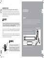
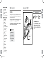
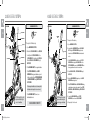
3.1AE 4.1AE ELLIPTICAL OWNER’S MANUAL MANUEL DU PROPRIÉTAIRE DE L’EXERCISEUR ELLIPTIQUE MANUAL DEL PROPIETARIO DE LA MÁQUINA ELÍPTICA Read the ELLIPTICAL guide before using this owner’s manual. Lire le GUIDE D’UTILISATION DE L’EXERCISEUR ELLIPTIQUE avant de se servir du présent MANUEL DU PROPRIÉTAIRE. Lea la GUÍA DEL USUARIO DE LA MÁQUINA ELÍPTICA antes de usar este MANUAL DEL PROPIETARIO. 31AE_41AE_OM_Rev1_7.indd 1 7/13/11 11:08 AM DANGER To reduce the risk of electrical shock: Always unplug the elliptical from the electrical outlet immediately after using, before cleaning, performing maintenance and putting on or taking off parts. WARNING To reduce the risk of burns, fire, electrical shock or injury to persons: 4 •• If you experience any kind of pain, including but not limited to chest pains, nausea, dizziness, or shortness of breath, stop exercising immediately and consult your physician before continuing. •• When exercising, always maintain a comfortable pace. Do not sprint above 80 RPMs on this machine. •• To maintain balance, it is recommended to keep a grip on the handlebars while exercising, mounting or dismounting the machine. •• Do not turn pedal arms by hand. •• Make sure handlebars are secure before each use. •• Keep the topside of the foot support clean and dry. •• Care should be taken when mounting or dismounting the equipment. Before mounting or dismounting, move the pedal on the mounting or dismounting side to its lowest position and bring the machine to a complete stop. •• Do not wear clothes that might catch on any part of the elliptical. •• Always wear athletic shoes while using this equipment. •• Do not jump on the elliptical. •• At no time should more than one person be on the elliptical while in operation. •• This elliptical should not be used by persons weighing more than the specified user capacity in the OWNER’S MANUAL WARRANTY SECTION. Failure to comply will void the warranty. •• This elliptical is intended for in-home use only. Do not use this elliptical in any commercial, rental, school or institutional setting. Failure to comply will void the warranty. •• Do not use elliptical in any location that is not temperature controlled, such as but not limited to garages, porches, pool rooms, bathrooms, car ports or outdoors. Failure to comply will void the warranty. •• To prevent electrical shock, never drop or insert any object into any opening. •• Connect this exercise product to a properly grounded outlet only. 31AE_41AE_OM_Rev1_7.indd 4-5 WARNING To reduce the risk of burns, fire, electrical shock or injury to persons: •• •• •• •• •• •• •• •• •• •• •• •• •• Keep power cord away from heated surfaces. Do not carry this unit by its supply cord or use the cord as a handle. Do not use other attachments that are not recommended by the manufacturer. Attachments may cause injury. Do not operate where aerosol (spray) products are being used or when oxygen is being administered. Use the elliptical only as described in the elliptical guide and owner’s manual. Disconnect all power before servicing or moving the equipment. To clean, wipe surfaces down with soap and slightly damp cloth only; never use solvents. (See MAINTENANCE) The elliptical should never be left unattended when plugged in. Unplug from outlet when not in use, and before putting on or taking off parts. Do not operate under blanket or pillow. Excessive heating can occur and cause fire, electric shock, or injury to persons. At NO time should pets or children under the age of 13 be closer to the elliptical than 10 feet. At NO time should children under the age of 13 use the elliptical. Children over the age of 13 or disabled persons should not use the elliptical without adult supervision. Never operate the elliptical if it has a damaged cord or plug, if it is not working properly, if it has been dropped or damaged, or immersed in water. Return the elliptical to a service center for examination and repair. To disconnect, turn all controls to the off position, then remove plug from outlet. Do not remove the console covers unless instructed by Customer Tech Support. Service should only be done by an authorized service technician It is essential that your elliptical is used only indoors, in a climate controlled room. If your elliptical has been exposed to colder temperatures or high moisture climates, it is strongly recommended that the elliptical is warmed up to room temperature before first time use. Failure to do so may cause premature electronic failure and may also void the manufacturer’s warranty. 5 7/13/11 11:08 AM GROUNDING INSTRUCTIONS If your elliptical has power incline with a 3-prong plug, you must follow these grounding instructions. This product must be grounded. If a elliptical should malfunction or breakdown, grounding provides a path of least resistance for electrical current to reduce the risk of electrical shock. This product is equipped with a cord having an equipment-grounding conductor and a grounding plug. The plug must be plugged into an appropriate outlet that is properly installed and grounded in accordance with local codes and ordinances. WARNING DANGER Improper connection of the equipment-grounding conductor can result in a risk of electric shock. Check with a qualified electrician or serviceman if you are in doubt as to whether the product is properly grounded. Do not modify the plug provided with the product. If it will not fit the outlet, have a proper outlet installed by a qualified electrician. This product is for use on a nominal 110-120 Volt circuit and has a grounding plug that looks like the plug in the illustration. Make sure that the product is connected to an outlet having the same configuration as the plug. No adapter should be used with this product. This product must be used on a dedicated circuit. To determine if you are on a dedicated circuit, shut off the power to that circuit and observe if any other devices lose power. If so, move devices to a different circuit. Note: There are usually multiple outlets on one circuit. This elliptical should be used with a minimum 15-amp circuit. WARNING Connect this exercise product to a properly grounded outlet only. 3-POLE GROUNDED OUTLET GROUNDING PIN 6 31AE_41AE_OM_Rev1_7.indd 6-7 ASSEMBLY Never operate product with a damaged cord or plug even if it is working properly. Never operate any product if it appears damaged, or has been immersed in water. Contact Customer Tech Support for replacement or repair. There are several areas during the assembly process that special attention must be paid. It is very important to follow the assembly instructions correctly and to make sure all parts are firmly tightened. If the assembly instructions are not followed correctly, the elliptical could have frame parts that are not tightened and will seem loose and may cause irritating noises. To prevent damage to the elliptical, the assembly instructions must be reviewed and corrective actions should be taken. Before proceeding, find your elliptical’s serial number located on a white barcode sticker on the front stabilizer tube and enter it in the space provided below. SERIAL NUMBER LOCATION ENTER YOUR SERIAL NUMBER AND MODEL NAME IN THE BOXES BELOW: SERIAL NUMBER: EP MODEL NAME: AFG ELLIPTICAL » Refer to the SERIAL NUMBER and MODEL NAME when calling for service. 7 7/13/11 11:08 AM RESISTANCE LEVEL TOGGLES INCLINE LEVEL TOGGLES USB PORT SPEAKERS USB PORT SPEAKERS CONSOLE 3.1AE AERO HAND GRIPS IPOD/MP3 PLAYER POCKET IPOD/MP3 PLAYER POCKET CONSOLE 4.1AE UPPER HANDLEBAR CONSOLE CONTROLS AND DISPLAY WINDOWS WARNING CONSULT A PHYSICIAN PRIOR TO USING ANY EXERCISE EQUIPMENT. POSSIBILITY OF SERIOUS INJURY IF EQUIPMENT IS USED IMPROPERLY. READ INSTRUCTION MANUAL BEFORE USING. KEEP CHILDREN OFF AND AWAY FROM THIS EQUIPMENT. FOR CONSUMER USE ONLY. AVERTISSEMENT PULSE GRIPS WARNING CONSOLE MAST WATER BOTTLE HOLDER CONSULT A PHYSICIAN PRIOR TO USING ANY EXERCISE EQUIPMENT. POSSIBILITY OF SERIOUS INJURY IF EQUIPMENT IS USED IMPROPERLY. READ INSTRUCTION MANUAL BEFORE USING. KEEP CHILDREN OFF AND AWAY FROM THIS EQUIPMENT. FOR CONSUMER USE ONLY. AVERTISSEMENT CONSULTER UN MÉDECIN AVANT D’UTILISER TOUT ÉQUIPEMENT D’EXERCICE. TOUTE UTILISATION INCORRECTE PEUT OCCASIONNER DE GRAVES BLESSURES. LIRE LE MANUEL DU PROPRIÉTAIRE AVANT DE SE SERVIR DE L’APPAREIL. TENIR LES ENFANTS À DISTANCE DE L’APPAREIL. À L’USAGE DU CLIENT SEULEMENT. LOWER HANDLEBAR ADVERTENCIA CONSULTE A UN MÉDICO ANTES DE USAR CUALQUIER EQUIPO DE ACONDICIONAMIENTO FÍSICO. EXISTE LA POSIBILIDAD DE SUFRIR LESIONES GRAVES SI EL EQUIPO SE USA INCORRECTAMENTE. LEER EL MANUAL DEL PROPIETARIO ANTES DE USAR EL EQUIPO. NO DEJE QUE LOS NIÑOS SE ACERQUEN A ESTE EQUIPO. ESTE EQUIPO ES SÓLO PARA EL USO DEL CONSUMIDOR. UPPER HANDLEBAR CONSOLE CONTROLS AND DISPLAY WINDOWS PULSE GRIPS CONSOLE MAST WATER BOTTLE HOLDER CONSULTER UN MÉDECIN AVANT D’UTILISER TOUT ÉQUIPEMENT D’EXERCICE. TOUTE UTILISATION INCORRECTE PEUT OCCASIONNER DE GRAVES BLESSURES. LIRE LE MANUEL DU PROPRIÉTAIRE AVANT DE SE SERVIR DE L’APPAREIL. TENIR LES ENFANTS À DISTANCE DE L’APPAREIL. À L’USAGE DU CLIENT SEULEMENT. LOWER HANDLEBAR ADVERTENCIA POWER SWITCH AND POWER CORD SOCKET TOP CAP CONSULTE A UN MÉDICO ANTES DE USAR CUALQUIER EQUIPO DE ACONDICIONAMIENTO FÍSICO. EXISTE LA POSIBILIDAD DE SUFRIR LESIONES GRAVES SI EL EQUIPO SE USA INCORRECTAMENTE. LEER EL MANUAL DEL PROPIETARIO ANTES DE USAR EL EQUIPO. NO DEJE QUE LOS NIÑOS SE ACERQUEN A ESTE EQUIPO. ESTE EQUIPO ES SÓLO PARA EL USO DEL CONSUMIDOR. POWER SWITCH AND POWER CORD SOCKET TOP CAP STABILIZER TUBE CRANK STABILIZER TUBE CRANK MAIN FRAME PIVOTING FOOT PADS MAIN FRAME PIVOTING FOOT PADS LOWER LINK ARM GUIDE RAIL SET PEDAL ARM GUIDE RAIL SET REAR COVER 8 31AE_41AE_OM_Rev1_7.indd 8-9 CAUTION ATTENTION PRECAUCIÓN KEEP HANDS AND FEET AWAY FROM THIS AREA. GARDER LES MAINS ET LES PIEDS LOIN DE CETTE REGION. MANTENGA LAS MANOS Y LOS PIES LEJOS DE ESTA ÁREA. PEDAL ARM REAR COVER CAUTION ATTENTION PRECAUCIÓN KEEP HANDS AND FEET AWAY FROM THIS AREA. GARDER LES MAINS ET LES PIEDS LOIN DE CETTE REGION. MANTENGA LAS MANOS Y LOS PIES LEJOS DE ESTA ÁREA. LOWER LINK ARM 9 7/13/11 11:08 AM TOOLS INCLUDED: ALL MODELS 10 FF 8 mm L-Wrench FF 5 mm L-Wrench FF 13/15 mm Flat Wrench FF Screwdriver FF 5 mm L-wrench/Screwdriver PARTS INCLUDED: FF 1 Stabilizer Tube FF 1 Guide Rail Set FF 2 Pedal Arms FF 2 Lower Handlebars FF 2 Upper Handlebars FF 2 Lower Link Arms With Footpads FF 1 Top Cap (2 pieces) FF 1 Console Mast FF 1 Console Mast Boot FF 1 Console FF 2 Handlebar Caps FF 1 Water Bottle Holder FF 1 Rear Cover FF 1 Audio Adapter Cable FF 1 Power Cord FF 1 Hardware Kit 3.1AE only: FF 2 Handlebar Boots 4.1AE only: FF 2 Handlebar Covers FF 2 Aero Hand Grips FF 1 iPod® Dock Rubber Plug FF 1 Polar® Chest Strap 31AE_41AE_OM_Rev1_7.indd 10-11 PRE ASSEMBLY ASSEMBLY STEP 1 UNPACKING HARDWARE FOR STEP 1 : Unpack the product where you will be using it. Place the elliptical carton on a level flat surface. It is recommended that you place a protective covering on your floor. Never open box when it is on its side. NOTE: During each assembly step, ensure that ALL nuts and bolts are in place and partially threaded in before completely tightening any ONE bolt. BOLT (A) 30 mm Qty: 4 ARC WASHER (C) 17 mm Qty: 4 ALL MODELS STABILIZER TUBE NOTE: A light application of grease may aid in the installation of hardware. Any grease, such as lithium bike grease is recommended. NEED HELP? If you have questions or if there are any missing parts, contact Customer Tech Support. Contact information is located on the back panel of this manual. SPRING WASHER (B) 15 mm Qty: 4 A Open hardware for step 1. B Attach the stabilizer tube to the main frame using 2 bolts (a), 2 spring washers (b) and 2 arc washers (C) on each side. ARC WASHERS (C) SPRING WASHERS (B) BOLTS (A) MAIN FRAME 11 7/13/11 11:08 AM ASSEMBLY STEP 2 ASSEMBLY STEP 3 HARDWARE FOR STEP 2 : 4.1AE SHOWN FLAT WASHER (D) 16 mm Qty: 4 BOLT (F) 20 mm Qty: 4 HARDWARE FOR STEP 3 : 4.1AE SHOWN SPRING WASHER (E) 15 mm Qty: 4 FLAT WASHER (H) 20 mm Qty: 4 BOLT (G) 35 mm Qty: 4 BOLTS (L) BOLTS (F) BOLT (L) 15 mm Qty: 4 FLAT WASHER (M) 23 mm Qty: 4 WAVY WASHER (N) 22.5 mm Qty: 2 BOLT (O) 20 mm Qty: 2 SPRING WASHER (B) 15 mm Qty: 2 FLAT WASHER (K) 20 mm Qty: 2 FLAT WASHERS (M) SPRING WASHER (I) 18 mm Qty: 4 SPRING WASHERS (E) FLAT WASHERS (D) NUT (J) Qty: 4 CONSOLE MAST CONSOLE CABLE MAIN FRAME INCLINE BRACKET NUTS (J) SPRING WASHERS (I) FLAT WASHERS (H) MAIN FRAME A Open hardware for step 2. B Attach the guide rail set to the main frame using 4 bolts (F), 4 spring washers (e) and 4 flat washers (D). Note: Be careful not to pinch any wires while attaching the console mast. A Open hardware for step 3. B Carefully pull the console cable through the console mast using the twist tie located inside the console mast. C Attach console mast to main frame using 4 flat washers (M) and 4 bolts (L). D Slide wavy washer (N) over crank followed by pedal arm as shown. Rest pedal arm wheel on guide rail. E Attach the pedal arm to the crank using 1 flat washer (k), 1 spring washer (b) and 1 bolt (O). F Repeat steps D–E on the opposite side of the elliptical. C Attach the guide rail set to the BOLTS (G) GUIDE RAIL SET INCLINE BRACKET using 4 bolts (G), 4 flat washers (H), 4 spring washers (I) and 4 nuts (j). CRANK PEDAL ARM WAVY WASHER (N) FLAT WASHER (K) GUIDE RAIL PEDAL ARM WHEEL 12 31AE_41AE_OM_Rev1_7.indd 12-13 SPRING WASHER (B) BOLT (O) 13 7/13/11 11:08 AM ASSEMBLY STEP 4 ASSEMBLY STEP 5 HARDWARE FOR STEP 4 : 4.1AE SHOWN FLAT WASHER (P) 27 mm Qty: 4 WAVY WASHER (Q) 29 mm Qty: 2 SPRING WASHER (S) 15.4 mm Qty: 2 BOLT (T) SPRING WASHER (S) FLAT WASHER (P) PEDAL ARM BRACKET LOWER LINK ARM B Slide 1 flat washer (P), 1 wavy washer (Q) and another flat washer (P) onto the LOWER LINK ARM. 31AE_41AE_OM_Rev1_7.indd 14-15 RUBBER WASHER (U) 26 mm Qty: 2 RUBBER WASHER (U) D Attach the lower link arm to the pedal arm bracket using 1 flat washer (R), 1 spring washer (S) and 1 bolt (T). FLAT WASHER (H) 20 mm Qty: 4 BOLT (W) 20 mm Qty: 2 FLAT WASHERS (V) FLAT WASHERS (H) A Open hardware for step 5. BOLT (W) B Slide 1 rubber washer (U) and 1 flat washer (V) onto the console mast. HANDLEBAR CAP SPRING WASHER (B) LOWER HANDLEBAR FLAT WASHER (V) 25 mm Qty: 4 SPRING WASHER (B) 15 mm Qty: 2 CONSOLE MAST C Slide the lower link arm into the pedal arm bracket. E 14 BOLT (T) 20 mm Qty: 2 Open hardware for step 4. WAVY WASHER (Q) FLAT WASHER (R) FLAT WASHER (R) 20 mm Qty: 2 A FLAT WASHER (P) HARDWARE FOR STEP 5 : 4.1AE SHOWN C Slide lower handlebar onto console mast and attach using 1 flat washer (V), 1 flat washer (h), 1 handlebar cap, 1 flat washer (h), 1 spring washer (b) and 1 bolt (W). D Repeat steps B–C on the opposite side of the elliptical. Repeat steps B–D on the opposite side of the elliptical. 15 7/13/11 11:08 AM ASSEMBLY STEP 6 ASSEMBLY STEP 7 HARDWARE FOR STEP 6 : 4.1AE SHOWN TEFLON WASHER (X) 28.4 mm Qty: 4 SPRING WASHER (B) 15 mm Qty: 2 FLAT WASHER (Y) 17 mm Qty: 2 WATER BOTTLE HOLDER SCREW (BB) 20 mm Qty: 2 CONSOLE MAST BOLT (Z) 70 mm Qty: 2 A Open hardware for step 6. Remove zip tie securing axle in lower link arm. B Align end of lower link arm with bracket on bottom of lower handlebar. LOWER HANDLEBAR FLAT WASHER (Y) SPRING WASHER (B) BOLT (Z) LOWER LINK ARM C Place teflon washers (X) on both sides of the lower link arm. While holding teflon washers (X) slide lower link arm into bottom end of lower handlebar. D Secure the joint with 1 flat washer (Y), 1 spring washer (b),1 bolt (Z) and secure with 1 nut (AA). E Repeat steps B–D on the opposite side of the elliptical. Open hardware for step 7. B Slide top cap and top cap rear cover over console mast and snap into place. C Insert console mast boot over top cap TOP CAP and snap into place. SCREWS (CC) REAR CAP REAR STABILIZER 31AE_41AE_OM_Rev1_7.indd 16-17 A CONSOLE MAST BOOT TEFLON WASHERS (X) 16 SCREW (CC) 15 mm Qty: 2 TOP CAP REAR COVER NUT (AA) Qty: 2 SCREWS (BB) NUT (AA) HARDWARE FOR STEP 7 : 4.1AE SHOWN D Slide water bottle holder over console mast and attach using 2 screws (BB). E Slide rear cap over rear stabilizer and attach using 2 screws (CC). Note: Be careful not to pinch any wires while tightening screws. 17 7/13/11 11:08 AM 3.1AE ASSEMBLY STEP 8 4.1AE ASSEMBLY STEP 8 HARDWARE FOR STEP 8 : 3.1AE SHOWN 3.1AE BOLT (DD) 12 mm Qty: 4 CONSOLE CABLES CONSOLE UPPER HANDLEBAR BOLTS (DD) PRE-INSTALLED SET SCREWS CONSOLE MAST HANDLEBAR BOOT LOWER HANDLEBAR * This step is for 3.1AE models only. A Open hardware for step 8. B Attach the 3 console cables to the console. C Carefully tuck the console cables into the console mast before attaching the console. Attach console to console mast using 4 bolts (DD). D Slide handlebar boots over upper handlebars. E Slide upper handlebars onto lower handlebars making sure handlebars are joined together completely. Secure upper handlebars to lower handlebars using pre-attached set screws. HARDWARE FOR STEP 8 : 4.1AE SHOWN BOLT (DD) 15 mm Qty: 4 HANDLEBAR WIRE AERO HAND GRIPS 18 31AE_41AE_OM_Rev1_7.indd 18-19 F Slide handlebar boots down to cover handlebar attachments. 3.1AE ASSEMBLY COMPLETE! * This step is for 4.1AE models only. A Open hardware for step 8. BOLTS (DD) UPPER HANDLEBAR PRE-INSTALLED SET SCREWS B Carefully pull the handlebar wire from the aero hand grip through the upper handlebar using the twist tie located inside the upper handlebar and then discard the twist tie. C Pull the handlebar wire from the bottom of the upper handlebar while sliding the aero hand grip onto the upper handlebar to prevent the handlebar wire from becoming pinched and create slack to connect the wire. HANDLEBAR WIRES D Attach aero hand grip to upper handlebar using 2 bolts (DD). LOWER HANDLEBAR E Guide the handlebar wire through the top of the lower handlebar and through the slot. F Slide upper handlebar onto lower handlebar making sure handlebars are joined together completely. Secure upper handlebar to lower handlebar using pre-installed set screws. Make sure upper handlebars are as far down as possible. Handlebars can be damaged If not secured correctly. Note: Be careful not to pinch any wires while attaching the console or handlebars. 4.1AE Note: Be careful not to pinch any wires while attaching the aero hand grips or handlebars. G Connect the handlebar wire from the upper handlebar to the wire from the console mast. H Repeat steps B – G on other side. 19 7/13/11 11:08 AM 4.1AE ASSEMBLY STEP 9 HARDWARE FOR STEP 9 : 4.1AE ONLY 4.1AE SCREW (EE) 15 mm Qty: 8 CONSOLE CONSOLE CABLES BOLTS (FF) UPPER HANDLEBAR CONSOLE MAST HANDLEBAR COVERS SCREWS (EE) CONSOLE WIRES Note: Be careful not to pinch any wires while attaching the console or handlebar covers. 20 31AE_41AE_OM_Rev1_7.indd 20-21 BOLT (FF) 12 mm Qty: 4 * This step is for 4.1AE only. A Open hardware for step 9. B Attach right handlebar covers over handlebars using 4 screws (EE). C Repeat on other side. D Connect the 5 console cables to the console. E Carefully tuck the console cables into the console mast before attaching the console. Attach console to console mast using 4 bolts (FF). ELLIPTICAL OPERATION This section explains how to use your elliptical’s console and programming. The BASIC OPERATION section in the elliptical guide has instructions for the following: • LOCATION OF THE Elliptical • POWER/GROUNDING INSTRUCTIONS • FOOT POSITIONING • MOVING the elliptical • LEVELING the elliptical • POWER/MANUAL INCLINE OPERATION • Using the HEART RATE function 4.1AE ASSEMBLY COMPLETE! 21 7/13/11 11:08 AM R 3.1AE CONSOLE OPERATION Note: There is a thin protective sheet of clear plastic on the overlay of the console that should be removed before use. time distance date clock A) LED display windows: time, distance, date and clock. A B) Alphanumeric display window: displays watts, calories, rpm, heart rate, speed and PROFILE™ display information. C 3.1AE watts B D r pm calories E) Change display button: used to scroll through display modes. Press to change display feedback during workout. change display press to switch 3.1AE D) Profile™ button: used to scroll through profile™ display modes. User must be selected before pressing. speed hear t r ate C) Dot matrix display window: displays workout level and progress. performance filing system E F) Start: press to begin exercising, start your workout or resume exercising after pause. G) Stop: press to pause/end your workout. Hold for 3 seconds to reset the console. H) programming button: used to select program, level and time, and other options. N Q P Q I) Incline J) Resistance keys: press to adjust incline in 5% increments. keys: press to adjust resistance. K) Quick adjust keypad: used to reach desired resistance or incline more quickly. IPOD COMPATIBLE L I F H 22 31AE_41AE_OM_Rev1_7.indd 22-23 SQ UTA R T I C K S TA R T L) Set incline key: used to change incline to level entered into keypad. M N) Audio in: plug your cd / mp3 player into the console using the included audio adaptor cable. J pr ogr amming contr ols BACK K ENTER STOP SET HOLD TO RE G M) Set level key: used to change resistance to level entered into keypad. O) Audio out/headphone jack: plug your headphones into this jack to listen to your music through the headphones. P) iPod®/MP3 pocket: stores iPod or MP3 player. Q) Speakers: music plays through speakers when your cd/mp3 player is connected to the console. R) USB Port: used for software updates. O 23 7/13/11 11:08 AM S 4.1AE CONSOLE OPERATION Note: There is a thin protective sheet of clear plastic on the overlay of the console that should be removed before use. time distance date clock A) LED display windows: time, distance, date and clock. A B) Alphanumeric display window: displays watts, calories, rpm, heart rate, speed and profile™ display information. C 4.1AE watts B D r pm calories E) Change display button: used to scroll through display modes. Press to change display feedback during workout. change display press to switch 4.1AE D) Profile™ button: used to scroll through profile™ display modes. User must be selected before pressing. speed hear t r ate C) Dot matrix display window: displays workout level and progress. performance filing system E F) iPod® controls: press to adjust your attached iPod audio settings. G) Start: press to begin exercising, start your workout or resume exercising after pause. H) Stop: press to pause/end your workout. Hold for 3 seconds to reset the console. O R Q R I) iPod®/ programming button: used to select program, level and time, and other options. Used to control iPod® (during workout only). J) Incline F L M N J G I 24 31AE_41AE_OM_Rev1_7.indd 24-25 K ipod contr ols BACK SQ UTA R T I C K S TA R T ENTER STOP SET HOLD TO RE K) Resistance keys: press to adjust incline in 5% increments. keys: press to adjust resistance. L) Quick adjust keypad: used to reach desired resistance or incline more quickly. M) Set incline key: used to change incline to level entered into keypad. N) Set level key: used to change resistance to level entered into keypad. O) Audio in: plug your cd / mp3 player into the console using the included audio adaptor cable. P) Audio out/headphone jack: plug your headphones into this jack to listen to your music through the headphones. H Q) iPod® docking station: used to dock and charge your ipod® (not included). P S) USB Port: used for software updates. R) Speakers: music plays through speakers when your cd/mp3 player is connected to the console. 25 7/13/11 11:08 AM GETTING STARTED distance time hear t r ate Simply press START to begin working out. Time will count up from 0:00. The resistance level will default to level 1. Incline will default to 0%. OR... B) Select a program Display windows • TIME: Shown as minutes : seconds. View the time remaining or the time elapsed in your workout. • DISTANCE: Shown as miles. Indicates distance traveled during your workout. • CALORIES: Calories burned during your workout. • HEART RATE (HR): Shown as BPM (beats per minute). Used to monitor your heart rate (displayed when contact is made with both pulse grips or when wearing Polar chest strap). • SPEED: Shown as MPH. Indicates how fast the foot pads are moving. 26 • DAte/clock: Displays date and time. 31AE_41AE_OM_Rev1_7.indd 26-27 • Watts: Displays current user power output. 1) Select guest, user 1 or user 2 using on the programming button and press enter to confirm. • RPM: Rotations Per Minute. 2) Select weight and press ENTER. • Resistance: Shows the current level of resistance. Will be displayed in the alphanumeric window. • INCLINE: Shown as percent. Indicates the incline level of the power ramp. Will be displayed in the alphanumeric window. • PROFILE™ display: When PROFILE is activated, the PROFILE™ information is displayed in the LED windows. Use the PROFILE™ button to change display information. More information is on page 37. ™ 3) Select a program using on the programming button and press enter to confirm. Note: if you press start before pressing enter, the program will begin and counts up from 0:00 for the Manual program, and counts down from 30:00 for all other programs. The level defaults to 1. 4) Complete the program setup using on the programming button and press enter to confirm after each step. 5) When setup is complete, press start to begin your workout. 4) Review settings: You can review your settings at any time while in setup mode. Press enter to scroll through settings. Programming Button BACK ALL MODELS 3) Settings include: Month, Day, Year, Hour, Minute, and am/pm. A) Quick start up speed 1) Enter Setup mode: Press and hold the 1 and 2 keys for 3 seconds. on the programming 2) Use button to change settings and press enter to confirm. 3) You have the following options to start your workout: r pm watts calories 2) Plug in the power cord and turn the elliptical ON. (Switch is located at the bottom-front of the elliptical.) clock date ALL MODELS Date and clock setup 1) Check to make sure no objects are nearby that will hinder the movement of the elliptical. 5) Exit setup mode: To confirm the date and time, press and hold enter for 3 seconds. ENTER To CLEAR SELECTION/ reset the console 4.1AE Hold stop key for 3 seconds. Finishing your workout BACK ENTER 3.1AE When your workout is complete, the display will flash “WORKOUT COMPLETE” and beep. Your workout information will stay displayed on the console for 30 seconds and then reset. 27 7/13/11 11:08 AM PROGRAM information NOTE: If resistance or incline are changed during your workout, the remaining segments will be affected accordingly. P1 MANUAL: Manually adjust your resistance and incline levels as you work out toward a time-based goal. ALL MODELS P2 INTERVALS: Alternating levels of resistance build endurance in this time-based workout with 16 levels to choose from. TIME Level 1 2 3 4 5 6 7 8 9 10 11 12 13 14 15 16 28 31AE_41AE_OM_Rev1_7.indd 28-29 1 1 1 1 1 2 2 2 2 3 3 3 3 5 5 5 5 Warm-up 4 minutes 2 3 2 2 2 2 2 2 2 2 3 5 3 5 3 5 3 5 4 5 4 8 6 10 6 10 9 13 9 13 9 13 9 13 4 3 3 4 5 6 7 8 9 10 11 12 13 14 15 16 17 30 5 5 6 7 8 9 10 11 12 13 14 15 16 17 18 19 20 60 6 1 2 3 4 5 6 7 8 9 10 11 12 13 14 15 16 60 7 1 2 3 4 5 6 7 8 9 10 11 12 13 14 15 16 PROGRAM SEGMENTS - Repeat 30 30 60 30 60 60 8 9 10 11 12 13 5 5 1 5 1 1 6 6 2 6 2 2 7 7 3 7 3 3 8 8 4 8 4 4 9 9 5 9 5 5 10 10 6 10 6 6 11 11 7 11 7 7 12 12 8 12 8 8 13 13 9 13 9 9 14 14 10 14 10 10 15 15 11 15 11 11 16 16 12 16 12 12 17 17 13 17 13 13 18 18 14 18 14 14 19 19 15 19 15 15 20 20 16 20 16 16 30 14 5 6 7 8 9 10 11 12 13 14 15 16 17 18 19 20 30 15 5 6 7 8 9 10 11 12 13 14 15 16 17 18 19 20 60 16 1 2 3 4 5 6 7 8 9 10 11 12 13 14 15 16 Cool-down 4 minutes 17 18 19 20 3 2 2 1 3 2 2 1 4 2 2 1 5 2 2 1 6 5 3 2 7 5 3 2 8 5 3 2 9 5 3 2 10 5 4 3 11 8 4 3 12 10 6 3 13 10 6 3 14 13 9 5 15 13 9 5 16 13 9 5 17 13 9 5 P3 Weight loss: Fat-burning, time-based workout that steadily builds resistance for a gradual comedown, with 16 levels to choose from. TIME Level 1 2 3 4 5 6 7 8 9 10 11 12 13 14 15 16 1 1 1 1 1 2 2 2 2 3 3 3 3 5 5 5 5 WARM-UP 4 minutes 2 3 2 2 2 2 2 2 2 2 3 5 3 5 3 5 3 5 4 5 4 8 6 10 6 10 9 13 9 13 9 13 9 13 4 3 3 4 5 6 7 8 9 10 11 12 13 14 15 16 17 5 3 4 5 6 7 8 9 10 11 12 13 14 15 16 17 18 6 3 4 5 6 7 8 9 10 11 12 13 14 15 16 17 18 7 4 5 6 7 8 9 10 11 12 13 14 15 16 17 18 19 PROGRAM SEGMENTS - REPEAT Each segment lasts 60 seconds 8 9 10 11 12 13 4 5 5 5 5 4 5 6 6 6 6 5 6 7 7 7 7 6 7 8 8 8 8 7 8 9 9 9 9 8 9 10 10 10 10 9 10 11 11 11 11 10 11 12 12 12 12 11 12 13 13 13 13 12 13 14 14 14 14 13 14 15 15 15 15 14 15 16 16 16 16 15 16 17 17 17 17 16 17 18 18 18 18 17 18 19 19 19 19 18 19 20 20 20 20 19 14 4 5 6 7 8 9 10 11 12 13 14 15 16 17 18 19 15 3 4 5 6 7 8 9 10 11 12 13 14 15 16 17 18 16 3 4 5 6 7 8 9 10 11 12 13 14 15 16 17 18 17 3 3 4 5 6 7 8 9 10 11 12 13 14 15 16 17 COOL-DOWN 4 minutes 18 19 2 2 2 2 2 2 2 2 5 3 5 3 5 3 5 3 5 4 8 4 10 6 10 6 13 9 13 9 13 9 13 9 20 1 1 1 1 2 2 2 2 3 3 3 3 5 5 5 5 ALL MODELS 29 7/13/11 11:08 AM program INFORMATION ALL MODELS P4 Constant Watts: This workout automatically adjusts the resistance to keep you within a set Watts range and maintains your desired level of exercise intensity. 1) Select Constant Watts program using and press enter on the programming button. 2) Set time using and press enter. 3) Select desired watts using and press enter. 4) Press start to being the program. P5 Muscle toner: Work toward higher resistance levels as you build strength and endurance with 10 levels to choose from. Level 1 2 3 4 5 6 7 8 9 10 1 1 1 2 2 3 3 4 4 4 4 30 31AE_41AE_OM_Rev1_7.indd 30-31 Warm Up 2 3 1 2 2 2 2 3 3 3 4 4 5 4 5 5 5 5 5 5 5 9 4 2 3 3 4 4 5 5 5 5 9 5 1 2 3 4 5 6 7 8 9 14 6 2 3 4 5 6 7 7 8 9 14 7 3 4 5 6 7 8 8 9 10 15 Program Segments - Repeat 8 9 10 11 4 3 2 1 5 4 3 2 6 7 8 7 7 8 9 8 8 9 10 9 9 10 10 10 8 9 9 10 9 10 10 11 10 11 11 12 15 16 16 17 12 2 1 6 7 8 9 10 11 12 17 13 3 2 5 6 7 8 9 10 11 16 14 2 3 4 5 6 7 8 9 10 15 15 1 2 2 3 3 4 4 4 5 8 Cool down 16 17 1 1 1 1 1 1 1 1 3 2 3 2 3 2 3 2 4 3 7 6 18 1 1 1 1 1 1 1 1 1 1 P6 Reverse train: Alternate forward (F) and backward (R) pedaling at varying resistance levels for a challenging workout that builds greater lower body and core strength, with 16 levels to choose from. TIME LEVEL 1 2 3 4 5 6 7 8 9 10 11 12 13 14 15 16 1 1 1 1 1 1 1 1 1 1 1 2 3 3 3 3 4 WARM-UP 4 minutes 2 3 1 1 1 1 1 1 1 1 2 3 2 3 2 3 2 3 1 1 1 1 2 2 3 3 4 4 4 5 5 6 6 7 4 2 2 2 3 3 4 4 5 2 2 3 4 5 6 7 8 F 30 5 3 4 5 6 7 8 9 10 11 12 13 14 15 16 17 18 R 60 6 2 3 4 5 6 7 8 9 10 11 12 13 14 15 16 17 F 90 7 3 4 5 6 7 8 9 10 11 12 13 14 15 16 17 18 R 60 8 1 2 3 4 5 6 7 8 9 10 11 12 13 14 15 16 F 90 9 2 3 4 5 6 7 8 9 10 11 12 13 14 15 16 17 R 45 10 3 4 5 6 7 8 9 10 11 12 13 14 15 16 17 18 F 60 11 1 2 3 4 5 6 7 8 9 10 11 12 13 14 15 16 R 45 12 2 3 4 5 6 7 8 9 10 11 12 13 14 15 16 17 F 90 13 3 4 5 6 7 8 9 10 11 12 13 14 15 16 17 18 R 90 14 1 2 3 4 5 6 7 8 9 10 11 12 13 14 15 16 F 30 15 2 3 4 5 6 7 8 9 10 11 12 13 14 15 16 17 R 30 16 3 4 5 6 7 8 9 10 11 12 13 14 15 16 17 18 COOL-DOWN 4 minutes 17 18 19 2 1 1 2 1 1 2 1 1 3 1 1 3 3 2 4 3 2 4 3 2 5 3 2 2 1 1 2 1 1 2 1 1 3 1 1 3 3 2 4 3 2 4 3 2 5 3 2 20 1 1 1 1 1 1 1 1 1 1 1 1 1 1 1 1 ALL MODELS 31 7/13/11 11:08 AM program INFORMATION P7 Oregon Trail: Experience a hike through the foothills with an alternating resistance workout for a time-based goal. Choose from 10 levels. ALL MODELS TIME LEVEL 1 2 3 4 5 6 7 8 9 10 1 1 1 1 1 1 1 1 1 2 2 WARM-UP 4 minutes 2 3 1 1 1 1 1 1 1 1 2 3 2 3 2 3 2 3 2 3 2 4 4 1 2 2 3 3 4 4 5 5 6 30 5 3 3 4 4 5 5 6 6 7 7 90 6 1 1 2 2 3 3 4 4 5 5 90 7 1 1 2 2 3 3 4 4 5 5 Program Segments - Repeat 30 30 90 30 90 90 8 9 10 11 12 13 3 3 1 3 1 1 3 3 1 3 1 1 4 4 2 4 2 2 4 4 2 4 2 2 5 5 3 5 3 3 5 5 3 5 3 3 6 6 4 6 4 4 6 6 4 6 4 4 7 7 5 7 5 5 7 7 5 7 5 5 30 14 3 3 4 4 5 5 6 6 7 7 30 15 3 3 4 4 5 5 6 6 7 7 90 16 1 1 2 2 3 3 4 4 5 5 COOL-DOWN 4 minutes 17 18 19 20 1 1 1 1 2 1 1 1 2 1 1 1 3 1 1 1 3 3 2 1 4 3 2 1 4 3 2 1 5 3 2 1 5 3 2 2 6 4 2 2 P8 THR zone: Simulate the intensity of your favorite sport as the program resistance automatically adjusts to maintain a set Target Heart Rate range. 1) Select THR Zone program using and press enter on the programming button. 2) Select TIME using and press enter on the programming button. 3) The HEART RATE window will flash showing the default target heart rate of 80 beats per minute. Select your target heart rate (from heart rate training chart) using on the programming button and press ENTER. 4) Press START to begin. P9 HR intervals (4.1AE only): Automatically adjusts peak and valley resistance levels within your desired heart rate. Perfect for providing an intense workout with recovery bursts. Time-based goal. 1) 2) 3) 4) 5) Set TOTAL WORKOUT TIME using on the programming button or the keypad and press ENTER. Set PEAK interval target heart rate using or the keypad and press enter. Set PEAK interval time using or the keypad and press enter. Set VALLEY interval target heart rate using or the keypad and press enter. Set VALLEY interval time using or the keypad and press enter. Press START to begin. Heart rate training The first step in knowing the right intensity for your training is to find out your maximum heart rate (max HR = 220 – your age). The age-based method provides an average statistical prediction of your max HR and is a good method for the majority of people, especially those new to heart rate training. The most precise and accurate way of determining your individual Target Heart Workout Example THR Your Recommended For Rate Zone Duration Zone (age 30) THR Zone max HR is to have it clinically tested by a cardiologist or exercise physiologist through the Very Hard < 5 min 171 – 190 bpm Fit persons and for athletic training 90 – 100% use of a maximal stress test. If you are over the age of 40, overweight, have been sedentary for Hard 2 – 10 min 152 – 171 bpm Shorter workouts 80 – 90% several years, or have a history of heart disease in your family, clinical testing is recommended. Moderate 10 – 40 min 133 – 152 bpm Moderately long workouts 70 – 80% This chart gives examples of the heart rate range for a 30 year old exercising at 5 different Longer and frequently repeated Light 40 – 80 min 114 – 133 bpm shorter exercises 60 – 70% heart rate zones. For example, a 30-year-old’s max HR is 220 – 30 = 190 bpm and 90% max Weight management and active Very Light 20 – 40 min 104 – 114 bpm recovery 50 – 60% HR is 190 × 0.9 = 171 bpm. 32 31AE_41AE_OM_Rev1_7.indd 32-33 ALL MODELS WARM UP WORK INTERVAL REST INTERVAL TIME 4:00 min The peak interval and valley interval segment times are preset by the user and are repeated until the cool down. RESISTANCE 0% Or user selects THR set by user for the peak and valley intervals. COOL DOWN 2:00 min 2:00 min 50% Current Resistance 0% NOTES: • The large LED dot matrix window displays your heart rate during exercise. The middle row represents your target heart rate (THR) and the other rows equal +/-2 heart beats. If you are working out beneath your THR, the LEDs below the middle row will illuminate. If you are over, the LEDs above the middle row will illuminate. Your current heart rate is represented by the flashing column and the window will refresh every 5 seconds. • There is a 4-minute warm-up built into this program at level 1 resistance. • After 4 minutes, the resistance will automatically adjust to bring your heart rate within 5 beats of the target number you selected at the beginning of the program. • If there is no heart rate detected, the unit will not change resistance levels up or down. • If your heart rate is 25 beats over your target zone the program will shut down. 33 7/13/11 11:08 AM program INFORMATION P10 Cardio boost (4.1AE only): Take your fitness goals to the next level with high-energy bursts that alternate resistance and incline combinations for greater results in less time. Choose from 10 levels. NOTE: All elevations are listed as a percent of total elevation. 4.1AE LEVEL 1 2 3 4 5 6 7 8 9 10 34 31AE_41AE_OM_Rev1_7.indd 34-35 TIME Segment # Incline Resistance Incline Resistance Incline Resistance Incline Resistance Incline Resistance Incline Resistance Incline Resistance Incline Resistance Incline Resistance Incline Resistance WARM UP 4:00 min 1 2 5 10 1 2 5 15 1 3 10 15 2 3 10 20 2 4 15 15 3 3 15 20 3 4 20 20 4 4 20 25 4 5 20 25 4 5 20 25 4 5 1:30 3 5 1 10 2 15 3 20 4 30 6 40 8 45 9 5 10 60 12 70 14 PROGRAM SEGMENTS - REPEAT :30 1:30 :30 1:30 30 1:30 4 5 6 7 8 9 15 5 15 5 30 5 3 1 3 1 6 1 25 10 25 10 35 10 5 2 5 2 7 2 35 15 35 15 40 15 7 3 7 3 8 3 45 20 45 25 5 25 9 4 9 5 10 5 55 30 55 35 60 35 11 6 11 7 12 7 65 40 65 45 70 45 13 8 13 9 14 9 70 45 70 50 75 50 14 9 14 10 15 10 75 50 75 55 80 55 15 10 15 11 16 11 80 60 80 65 85 65 16 12 16 13 17 13 90 70 90 75 90 75 18 14 18 15 18 15 :30 10 30 6 35 7 40 8 5 10 60 12 70 14 75 15 80 16 85 17 90 18 COOL DOWN 4:00 min 11 12 10 5 2 1 10 5 2 1 15 10 3 2 15 10 3 2 25 15 5 3 25 15 5 3 25 15 5 3 25 15 5 3 25 15 5 3 25 15 5 3 P11 MOUNTAIN CLIMB (4.1AE only): Combinations of resistance and incline gradually increase for an effective, climbsimulated workout that boosts strength and endurance, with 10 levels to choose from. NOTE: All elevations are listed as a percent of total elevation. LEVEL 1 2 3 4 5 6 7 8 9 10 TIME Segment # Incline Resistance Incline Resistance Incline Resistance Incline Resistance Incline Resistance Incline Resistance Incline Resistance Incline Resistance Incline Resistance Incline Resistance WARM UP 4:00 min 1 2 5 10 1 2 5 15 1 3 10 15 2 3 10 20 2 4 15 15 3 3 15 20 3 4 20 20 4 4 20 25 4 5 20 25 4 5 20 25 4 5 1:00 3 15 4 20 6 30 7 40 8 50 9 60 10 70 11 80 12 90 13 100 14 1:00 4 15 4 20 6 30 7 40 8 50 9 60 10 70 11 80 12 90 13 100 14 1:00 5 15 5 20 7 30 9 40 10 50 11 60 12 70 13 80 14 90 15 100 16 1:00 6 10 5 15 7 25 9 35 10 45 11 55 12 65 13 75 14 85 15 90 16 PROGRAM SEGMENTS - REPEAT 1:00 1:00 1:00 1:00 1:00 7 8 9 10 11 10 10 10 10 10 6 6 6 6 5 15 15 15 15 15 8 8 8 8 7 25 25 25 25 25 10 10 10 10 9 35 35 35 35 35 11 12 12 11 10 45 45 45 45 45 12 13 13 12 11 55 55 55 55 55 13 14 14 13 12 65 65 65 65 65 14 15 15 14 13 75 75 75 75 75 15 16 16 15 14 85 85 85 85 85 16 17 17 16 15 90 90 90 90 90 17 18 18 17 16 1:00 12 15 5 20 7 30 9 40 10 50 11 60 12 70 13 80 14 90 15 100 16 1:00 13 15 4 20 6 30 7 40 8 50 9 60 10 70 11 80 12 90 13 100 14 1:00 14 15 4 20 6 30 7 40 8 50 9 60 10 70 11 80 12 90 13 100 14 COOL DOWN 4:00 min 15 16 5 5 3 2 10 10 3 2 15 15 3 2 20 20 3 2 25 25 4 3 30 30 4 3 35 35 5 4 40 40 5 4 40 40 5 4 40 40 5 4 4.1AE 35 7/13/11 11:08 AM CUSTOM PROGRAMS (4.1AE HAS 3 CUSTOM PROGRAMS, 3.1AE HAS 2 CUSTOM PROGRAMS) 1) Select custom 1, 2 or 3 program using programming button. ALL MODELS 2) Set time using Programming Button and press enter on the and press enter on the programming button. and press enter on the programming 3) Set the resistance profiles using button after each segment is set to the desired level (repeat until all 15 segments are set). and press enter on the programming 4) Next, set the incline profiles using button after each segment is set to the desired level (repeat until all 15 segments are set). NOTE: if back is pressed on the programming button, it will take you back to previous segment. 5) Press start to begin the program. NOTE: to reset the memory, press and hold enter for 5 seconds. BACK ENTER PROFILE™ PERFORMANCE TRACKER Research shows that those who journal their fitness routines or workouts, on average, achieve greater success than those who do not. Because your new elliptical is equipped with AFG’s exclusive PROFILE™ Performance Tracker, you’ve taken an important step towards achieving your fitness goals. The integrated PROFILE™ software allows you to track your fitness progress over time without the need for paper journals or logs. With PROFILE™, you can easily compare your current workout to your last, average or lifetime workout totals. With quick access to feedback like duration of workout or calories burned during previous workouts, you’ll be able to see the progress you’ve made. Read further to learn about how PROFILE™ can help motivate you to enhance your performance. ALL MODELS 4.1AE SETUP BACK ENTER 3.1AE To activate PROFILE™, a user MUST be chosen before the program begins. To select a USER 1 or 2, use the PROGRAMMING BUTTON and press ENTER to confirm. All accumulated data specifically relates to the user that is chosen. NOTE: If no user is selected and clock and date are not set, no data will be tracked. RESET Reset all recorded information for USER 1 or USER 2 by selecting the user and then holding down the PROFILE™ button for 10 seconds. Note: This step is permanent and will delete ALL previously accumulated data for the chosen user. ACCUMULATED DATA Once PROFILE™ is activated, you can scroll through your accumulated data in multiple formats by pressing the PROFILE™ button. A workout is saved when: the program ends, the console is paused and not resumed within 5 minutes, or the STOP button is held to reset the console. 36 31AE_41AE_OM_Rev1_7.indd 36-37 LAST WORKOUT: This option allows you to view your accumulated data from your last workout. The current workout becomes the last workout once a program has ended or the console has been reset. The following information will be shown in each display window: • TIME - Total time of last workout. • DISTANCE - Total distance of last workout. • WATTS - Average watts of last workout. • RPM - Average RPM of last workout. • CALORIES - Total calories burned of last workout. • SPEED - Average speed of last workout. 37 7/13/11 11:08 AM PROFILE™ Performance Tracker ACCUMULATED DATA 2) AVERAGE WORKOUT: This option allows you to see your average accumulated data for the last 30 workouts. The following ALL MODELS 38 information will be shown in each display window: • TIME - Average workout time. • DISTANCE - Average workout distance. • WATTS - Average watts of workout. • RPM - Average RPM. • CALORIES - Average calories burned. • SPEED - Average speed of workout. 3) WEEKLY GOAL: Indicates the weekly goal you set. “LEFT” – Indicates the time or distance you have left to complete to meet your weekly goal. TIME or DISTANCE – The total time or distance goal you selected and the time or distance you have left to complete to meet your weekly goal. • The “GOAL” and “LEFT” will display alternately every 3 seconds. • A “GOAL DONE” message will appear when goal is completed. • If the date and clock are not set and/or a weekly goal is not set, weekly goal will display zeros. • The time or distance left for the weekly goal will reset at the end of each week. 4) WEEKLY TOTAL: View your accumulated data from the last Sunday to the present day. NOTE: This data is based on week to date NOT the previous seven days. For instance, if you have not used the machine since Sunday, the console will read zeros. The following information will be shown in each display window: • TIME - Total time of workout. • DISTANCE - Total distance of workout. • WATTS - Average watts of weekly workout. • RPM - Average RPM of weekly workout. • CALORIES - Average calories burned. • SPEED - Average speed of weekly workout. NOTE: If the date and clock are not set, weekly total will default to the last workout data. 5) LIFETIME TOTAL: This option allows you to view the total accumulated data. The following information will be shown in each display window: • TIME - Total accumulated time. NOTE: If time is greater than 59:59, the time will no longer display minutes and will display hours only. • DISTANCE - Total accumulated distance. • WATTS - Average watts. • RPM - Average RPM. • CALORIES - Average calories burned. • SPEED - Average speed. 31AE_41AE_OM_Rev1_7.indd 38-39 PROFILE™ Performance Tracker WEEKLY GOAL SETUP 1) Select user 1 or user 2. 2) Press PROFILE™ button until it displays “weekly goal.” Press enter. 3) Use 4) to set a distance goal. If the distance is changed from 0.00, distance will be the goal. Use NOTE: you may only set a time or distance goal, not both. 5) Press enter to exit the weekly goal setup mode. to set a time goal (leave time at 0:00 if you want to set a distance goal). Press enter. ALL MODELS Using your CD / MP3 player 1) Connect the included audio adaptor cable to the audio in jack on the left of the console and the headphone jack on your cd / mp3 player. 2) Use your cd / mp3 player buttons to adjust song settings. 3) Remove the audio adaptor cable when not in use. 4) If you don’t want to use the speakers, you can plug your headphones into the audio out jack at the bottom of the console. Downloading a Software Update from AFGFitness.com Occasionally a software update may be available for your console, via the included USB port. Please visit http://www.afgfitness.com/customer-support/software-update/ to see if an update is available and get detailed instructions on how to download the latest software from your PC or Mac. NOTE: Performing a software update will delete all previously saved workout information. 39 7/13/11 11:08 AM iPod® docking station The iPod docking station is the entertainment solution for your workouts. Various iPod and iPhone models with a dock connector can fit this dock. 4.1AE READY Connect your Nike Plus-compatible device to the built-in Made for iPod connector on Nike + iPod compatible fitness equipment. Using the iPod docking station (ipod not included) RUBBER PLUG 1) Remove the rubber plug from bottom of the docking station. AUDIO IN JACK FOR NON-IPOD PLAYERS IPOD® DOCKING STATION IPOD® CONTROLS AUDIO OUT JACK 40 31AE_41AE_OM_Rev1_7.indd 40-41 SET Full console controls and built-in SonicSurround™ speakers make it easy to exercise to your favorite workout playlist. 2) Plug in your iPod/iPhone by matching the dock connector pin on the console with the dock connector on your iPod/ iPhone. NOTE: Once you have connected the device to the docking station, please allow 10 seconds for docking station to authenticate before it will be fully functional. GO Start walking or running. Your distance, time, and calories burned are recorded as you go. It’s all automatically saved on your iPod or iPhone. 3) Use the controls below the dock to adjust volume and music selection. Use the programming button to access full iPod functionality. NOTE: If you don’t want to use the speakers, you can plug your headphones into the audio out jack at the bottom of the console. SYNC When you’re done with your workout, connect your iPod or iPhone to your computer. iTunes syncs your workout data to nikeplus.com. Every workout and every run is there, ready for you to review. Replace the rubber plug into the bottom of the docking station when the station is not in use or for use with other media players. BACK ENTER NOTE: Audio will not play through speakers if audio adaptor cable is plugged in while iPod/iPhone is in the docking station. 4.1AE BACK ENTER “Made for iPod” means that an electronic accessory has been designed to connect specifically to iPod and has been certified by the developer to meet Apple performance standards. Apple is not responsible for the operation of this device or its compliance with safety and regulatory standards. iPod is a trademark of Apple Inc., registered in the U.S. and other countries. 41 7/13/11 11:08 AM NIKE + OPERATION Requirements 4.1AE LIMITED HOME-USE WARRANTY Nike Plus – compatible iPod or iPhone (See www.apple.com/nikeplus for more information). Before syncing your Apple device to your computer, you must first create a free Nike Plus account at www.nikerunning.com and download the latest iTunes software (www.apple.com/itunes). GETTING STARTED 1) Before connecting your Apple device to the elliptical, you must first turn on Nike Plus on the device. 2) Dock your Apple device and wait for authentication to complete. This may take up to 10 seconds. After authentication is complete, your iPod-specific console controls will be active (see next page). 3) See Console Operation on page 25 and start your workout. 4) If your iPod or iPhone is Nike Plus compatible, your workout will begin recording automatically to your Nike Plus compatible device. The console will display, “RECORDING WORKOUT TO IPOD.” 5) When your workout is complete, the display will verify by displaying “CONGRATULATIONS WORKOUT RECORDED. CONNECT YOUR IPOD TO YOUR COMPUTER AND SEE YOUR WORKOUT AT NIKEPLUS. COM.” If you happen to stop your workout before your workout is complete, press and hold stop for 5 seconds. This will record your data to your Nike Plus-compatible device. 6) Remove your Nike Plus compatible device and sync with iTunes. 7) Log into your Nike Running account to review and track your workouts. 42 31AE_41AE_OM_Rev1_7.indd 42-43 43 7/13/11 11:08 AM WEIGHT CAPACITY 3.1AE = 325 lbs (147.4 kilograms) 4.1AE = 350 lbs (158.8 kilograms) FRAME • LIFETIME AFG warrants the frame against defects in workmanship and materials for the lifetime of the original owner, so long as the device remains in the possession of the original owner. (The frame is defined as the welded metal base of the unit and does not include any parts that can be removed.) BRAKE • LIFETIME AFG warrants the brake against defects in workmanship and materials for the lifetime of the original owner, so long as the device remains in the possession of the original owner. Labor or installation of brake is not covered under the brake warranty. ELECTRONICS & PARTS• 3.1AE: 3 YEAR • 4.1AE: 5 YEARS AFG warrants the electronic components, finish and all original parts for the period specified above from the date of original purchase, so long as the device remains in the possession of the original owner. LABOR • 3.1AE: 1 YEAR • 4.1AE: 2 YEARS AFG shall cover the labor cost for the repair of the device for the period specified above from the date of the original purchase, so long as the device remains in the possession of the original owner. 44 31AE_41AE_OM_Rev1_7.indd 44-45 SERVICE/RETURNS INCLINE MOTOR • 1 YEAR AFG warrants the incline motor mechanism and parts against defects in workmanship and materials for a period of one year from the date of original purchase, so long as the device remains in the possession of the original owner. EXCLUSIONS AND LIMITATIONS Who IS covered: • The original owner and is not transferable. What IS covered: • Repair or replacement of a defective motor, electronic component, or defective part and is the sole remedy of the warranty. What IS NOT covered: • Normal wear and tear, improper assembly or maintenance, or installation of parts or accessories not originally intended or compatible with the equipment as sold. • Damage or failure due to accident, abuse, corrosion, discoloration of paint or plastic, neglect, theft, vandalism, fire, flood, wind, lightning, freezing, or other natural disasters of any kind, power reduction, fluctuation or failure from whatever cause, unusual atmospheric conditions, collision, introduction of foreign objects into the covered unit, or modifications that are unauthorized or not recommended by AFG. • Incidental or consequential damages. AFG is not responsible or liable for indirect, special or consequential damages, economic loss, loss of property, or profits, loss of enjoyment or use, or other consequential damages of whatsoever nature in connection with the purchase, use, repair or maintenance of the equipment. AFG does not provide monetary or other compensation for any such repairs or replacement parts costs, including but not limited to gym membership fees, work time lost, diagnostic visits, maintenance visits or transportation. • Equipment used for commercial purposes or any use other than a single family or Household, unless endorsed by AFG for coverage. • Equipment owned or operated outside the US and Canada. • Delivery, assembly, installation, setup for original or replacement units or labor or other costs associated with removal or replacement of the covered unit. • Any attempt to repair this equipment creates a risk of injury. AFG is not responsible or liable for any damage, loss or liability arising from any personal injury incurred during the course of, or as a result of any repair or attempted repair of your fitness equipment by other than an authorized service technician. All repairs attempted by you on your fitness equipment are undertaken AT YOUR OWN RISK and AFG shall have no liability for any injury to the person or property arising from such repairs. • In-home service is available within 150 miles of the nearest authorized Service Provider (Mileage beyond 150 miles from an authorized service center is the responsibility of the consumer). • All returns must be pre-authorized. • The warranty is limited to replacing or repairing, at the servicer’s and/or manufacturer’s option, the same or comparable model. • Defective components may be requested to be returned to the manufacturer upon completion of warranty service using a prepaid return shipping label. If you have been advised to return parts and did not receive a label, please contact Customer Tech Support. • Replacement units, parts and electronic components reconditioned to as-new condition by the manufacturer or its vendors may sometimes be supplied as warranty replacement and constitute fulfillment of warranty terms. • This warranty gives you specific legal rights, and your rights may vary from states to state. • If you are out of the manufacturer’s warranty but have an extended warranty, refer to your extended warranty contract for contact information regarding requests for extended warranty service or repair. 45 7/13/11 11:08 AM 3.1AE Q23x6 46 31AE_41AE_OM_Rev1_7.indd 46-47 Ref # 1 2 3 4 5 6 7 8 9 10 11 12 13 14 15 18 AC1 AD1 AD2 AD3 AD3 AE1 AE2 AF1 AG1 AG2 AG3 AG4 AG5 AH1 AH2 AJ1 AK1 AN1 B12 B17 B20 B21 B22 C08 C09 C10 C12 D07 D08 D09 D10 D11 D12 D13 D14 D15 E08 E09 E10 E11 E13 E14 E15 E16 E17 E18 E19 Description Guide Rail Frame Set Console Mast Set Guide Rail Set; Right Guide Rail Set; Left Pedal Arm Set; Left Pedal Arm Set; Right Upper Handlebar Set; Left Upper Handlebar Set; Right Lower Handlebar Set; Left Lower Handlebar Set; Right Link Arm Set; Left Link Arm Set; Right Stabilizer Set Crank Sleeve Set Roller Set Pedal Axle Set Console Mast Guide Rail; Right Guide Rail; Left Leveler Frame Set Leveler Frame Set Pedal Arm; Left Pedal Arm; Right Guide Rail Frame Lower Handlebar; Left Lower Handlebar; Right Upper Handlebar; Left Upper Handlebar; Right Linkage Set Pedal Arm; Left Pedal Arm; Right Crank Set Elevation Connecting Frame Set Console Set Washer; Flat Clip; Standard Screw; Hex Head Washer; Flat Nut Water Bottle Holder Cap Sticker; Warning; Console set Cable Tie; Nylon Guide Rail Ornament; Nickel Screw; Button Head Foam; Single Side Screw; Button Head Washer; Flat Washer; Split Cable Tie; Nylon; Black Ribbon (WHITE) Pin Sleeve; Hang Arm Crank Pin Sleeve; Aluminum Casting Washer; Flat Screw; Button Head Screw; Button Head Screw; cylinder Bearing; Ball Washer; Flat Nut Bearing; Ball Bearing; Ball Bushing E20 E22 F10 F12 F13 F14 F16 F17 F18 G08 G09 G10 G12 G13 G18 G19 G20 G22 H05 H06 H10 H11 H12 H13 H14 J03 J04 J05 J06 K03 TROUSSE TROUSSE TROUSSE L01 L02 L03 L04 L05 L06 L07 M30 M31 M33 N71 P02 P03 P04 P05 P06 P07 P08 P09 P10 P11 P13 P14 P15 P17 P18 Q01 Q02 Q03 Q04 Washer; Wave Shim; Crank Sleeve Leveler Washer; Flat Washer; Wavy Washer End-Cap; Guide Rail Rivet Nut Clamp; External C-Shaped Adjustable Foot Pad Nut Foam; Handle Bar Cap; Tube; PVC; Black Screw; SET Cover; Hand Arm; Nylon Bushing Washer; Flat Washer; Flat Screw; Button Head Swivel Axle Cover; Arm Rest Screw; Button Head Bushing Link Arm Swivel Axle Cable Tie; Nylon Link Arm caps; Black End-Cap; Seat Pad Logo Label; PEDAL Screw; Flat head Screw; Socket head Nut Washer Screw Hardware Kit Adjustable Foot Pad Nut Documentation Manual; Assembly Stabilizer Set Bushing; Move Wheel; BLACK Wheel Set Washer; Flat Screw; Button Head Screw; Button Head Rivet nut Motor; AC Elevation Controller; Motor; AC Screw; Button Head Pulse Sensor Set Wire; Console Sensor Wire Screw; Button Head Wire; POWER SOCKET SET Power Switch; Large Circuit Breaker; 3 A/125 V Wire; CTRL BOARD PWR; BLACK Wire; CTRL BOARD PWR; WHITE Wire; Breaker socket connector; BLACK ECB Motor Wire ECB = Electronic Control Board Tie Strap Adhesive; NYLON66 Cable Tie; Nylon; Black Cable Tie; Nylon; 300L; White Screw; Button Head Screw; Truss Head Side Cover Side Cover Console Mast Boot; Rear Console Mast Boot; Front Q05 Q06 Q07 Q08 Q09 Q10 Q11 Q12 Q13 Q14 Q15 Q16 Q17 Q18 Q19 Q20 Q20 Q21 Q22 Q23 R01 R02 R03 R04 R05 R06 R07 R08 R09 R11 R13 R14 R15 R17 R18 R19 S01 S02 S03 V02 V03 V05 V05 V09 V12 V12 V12 V12 V16 V16 V16 V16 V19 Z01 Z02 Z03 Z04 Z06 Z07 Z09 Z10 Z11 Z12 Cover; Pedal arm Roller; Polyurethane; Black Cover; Pulley Cover; Pulley Link arm caps Pin Sleeve; Hang Arm Console Mast Boot; Top Cover; PA757K; STABILIZER Crank Cover; CRANK Foot Pad Foot Pad Pedal Pad Clip; Standard Pedal Pad Cover; Stabilizer Screw; Button Head Screw; Button Head Screw; Button Head Side Rail; FRAME Side Cover 2 Hole Bracket Axle, TRANSIMISSION Magnet; Spare; Single Pulley; POLY-V; -NYLON Flywheel Bearing; Ball Belt; Poly-V; RUBBER Screw; EB Nut; Hex Nut; NLK (Nylock) Key; Round; DUAL-END Snap Ring; External Fix Plate; Eye Bolt Nut; Lock Washer; Flat Screw; Button Head Washer; Flat Motor; ECB ECB = Electronic Control Board Tension Cable; ECB Screw; Button Head Logo Label; STABILIZER Cover Decorated Label; SIDE Cover Sticker; Warning Sticker; Warning Sales Label Sticker; Instruction; L; Sticker; Instruction; L; Sticker; Instruction; L; Sticker; Instruction; L; Sticker; Instruction; R; Sticker; Instruction; R; Sticker; Instruction; R; Sticker; Instruction; R; Sticker Round; Black Screw; Button Head Washer; Split Washer; ARC Screw; Socket head Washer; Split Washer; Flat Screw; Button Head Washer; Flat Nut; NLK (Nylock) Washer; Wavy Washer Z13 Z15 Z16 Z17 Z18 Z19 Z23 Z25 Z26 Z27 Z33 Z34 Z35 Z36 Z37 Washer; Flat Screw; Button Head Screw; Button Head Screw; Button Head Screw; Socket head Washer; Flat Screw; Button Head Washer; Flat Nut; NLK (Nylock) Washer; Flat Screw; Button Head Washer; Wavy Washer Washer; Flat Ring; Rubber Washer; Flat 3.1AE 47 7/13/11 11:08 AM 4.1AE Q27x6 48 31AE_41AE_OM_Rev1_7.indd 48-49 Ref # 1 2 3 4 5 6 7 8 9 10 11 12 13 14 15 16 17 18 AC1 AD1 AD2 AD3 AD3 AE1 AE2 AF1 AG1 AG2 AG3 AG4 AG5 AG6 AG7 AH1 AH2 AJ1 AK1 AN1 B12 B17 B20 B21 B22 C08 C09 C10 C12 C13 D07 D08 D09 D10 D11 D12 D13 D14 D15 E08 E09 E10 E11 E13 Description Guide Rail Frame Set Console Mast Set Guide Rail Set; Right Guide Rail Set; Left Pedal Arm Set; Left Pedal Arm Set; Right Upper Handlebar Set; Left Upper Handlebar Set; Right Lower Handlebar Set; Left Lower Handlebar Set; Right Link Arm Set; Left Link Arm Set; Right Stabilizer Set Crank Sleeve Set Roller Set Hand Grip Set; Left Hand Grip Set; Right Pedal Axle Set Console Mast Guide Rail; Right Guide Rail; Left Leveler Frame Set Leveler Frame Set Pedal Arm; -; L Pedal Arm; -;R Guide Rail Frame Lower Handlebar; Left Lower Handlebar; Right Upper Handlebar; Left Upper Handlebar; Right Linkage Set Keypad / Wire Set; Left Handlebar Keypad / Wire Set; Right Handlebar Link Arm; Left Link Arm; Right Crank Set Elevation Connecting Frame Set Console Set Washer; Flat Clip; STANDARD Screw; Hex Head Washer; Flat Nut; NLK (Nylock) Plastic Plate Cap; PVC Sticker; Warning;Console set Cable Tie; Nylon Wave Tube; CR11SP;_14x_10.7;200m/coil Guide Rail Ornament; Nickel Screw; Button Head Foam; Single Side Screw; Button Head Washer; Flat Washer; Split Cable Tie; Nylon; Black Ribbon (WHITE) Pin Sleeve; Hang Arm Crank Pin Sleeve; Aluminum Casting Washer; Flat Screw; Button Head Screw; Button Head Screw; cylinder E14 E15 E16 E17 E18 E19 E20 E22 F10 F12 F13 F14 F16 F17 F18 G12 G13 G18 G19 G20 G21 G23 G24 G27 G28 H05 H06 H09 H10 H11 H12 H13 J03 J04 J05 J06 K03 TROUSSE TROUSSE TROUSSE L01 L02 L03 L04 L05 L06 L07 M30 M31 M33 N71 P02 P03 P04 P05 P06 P07 P08 P09 P10 P11 P12 P13 P14 Bearing; Ball Washer; Flat Nut; NLK (Nylock) Bearing; Ball Bearing; Ball Bushing Washer; Wave Shim; Crank Sleeve Leveler Washer; Flat Washer; Wavy Washer End-Cap; Guide Rail Rivet nut. Clamp; External C-Shaped Adjustable Foot Pad Nut Cover Bushing Washer; Flat Washer; Flat Screw; Button Head Cable Tie; Nylon Hand Grip; Right Hand Grip; Left Screw; Flat head Screw; SET Screw; Button Head Bushing; Lower Pedal Arm Cable Tie; Nylon Link Arm Swivel Axle Cable Tie; Nylon Link Arm caps; Black End-Cap; Seat Pad Screw; Flat head Screw; Socket head Nut Washer; Flat Screw Manual Set Documentation Manual; Assembly Hardware Set Stabilizer Bushing; Move Wheel; BLACK Wheel Set Washer; Flat Screw; Button Head Screw; Button Head Rivet nut Motor; AC Elevation; 110V; 175 mm Controller; Motor; AC; 100V~240V Screw; Button Head Pulse Sensor Set Wire; Console; Down; 1200 mm Sensor Wire Screw; Button Head Wire; POWER SOCKET SET Power Switch; Large Circuit Breaker; 3A/125V Wire; CTRL BOARD PWR; BLACK Wire; CTRL BOARD PWR;;WHITE Wire; Breaker socket connector; BLACK ECB Motor Wire Connect Wire Switch; 700 mm Tie Strap Adhesive; NYLON Cable Tie; Nylon; Black P15 P16 P17 P18 P19 P21 Q01 Q02 Q03 Q04 Q05 Q06 Q07 Q08 Q09 Q10 Q11 Q12 Q13 Q14 Q15 Q16 Q17 Q18 Q19 Q20 Q21 Q22 Q23 Q24 Q25 Q26 Q27 R01 R02 R03 R04 R05 R06 R07 R08 R09 R11 R13 R14 R15 R18 R19 S01 S02 S03 V01 V02 V03 V05 V09 V12 V16 V19 Z01 Z02 Z03 Z04 Z06 Cable Tie; Nylon; 300L; White Connect Wire Switch Screw; Button Head Screw; Truss head Inside Receiver Set PWR Cord;USA;16AWG;Long 2M Side Cover; L Side Cover; R Console Mast Boot; Rear Console Mast Boot; Front Cover; Pedal arm; ABS Roller; Polyurethane; Black Cover; Pulley; L Cover; Pulley; R Link arm caps Pin Sleeve; Hang Arm Console Mast Boot; Top; Console Mast Cover; PA757K; STABILIZER Crank Cover; CRANK Foot Pad; L Foot Pad; R Pedal Pad Clip; Standard Pedal Pad Plastic Stabilizer Cover Screw; Button Head Screw; Button Head Rear Frame Cover Cover; RE Cover; F Cover; RE; ABS Cover; F; ABS; DM328; Console MAST Side Cover 2 Hole Bracket Axle, TRANSIMISSION Magnet; Spare; Single Pulley; POLY-V;-NYLON Flywheel Bearing; Ball Belt; Poly-V;RUBBER Screw; EB Nut; Hex Nut; NLK (Nylock) Key; Round; DUAL-END Snap Ring; External Fix Plate; Eye Bolt Nut; Lock Screw; Button Head Washer; Flat Motor: ECBG Tension Cable; ECB Screw; Button Head Logo Label; FRAME Cover; REAR Logo Label; STABILIZER Cover; REAR DECORATED Label; SIDE Cover Sticker; Warning SALES Label Sticker; Instruction; L Sticker; Instruction; R Sticker Round; Black Screw; Button Head Washer; Split Washer; ARC Screw; Socket head Washer; Split Z07 Z09 Z10 Z11 Z12 Z13 Z15 Z16 Z17 Z18 Z19 Z23 Z25 Z26 Z27 Z31 Z32 Z33 Z34 Z35 Z36 Z37 Washer; Flat Screw; Button Head Washer; Flat Nut; NLK (Nylock) Washer; Wavy Washer Washer; Flat Screw; Button Head Screw; Button Head Screw; Button Head Screw; Socket head Washer; Flat Screw; Button Head Washer; Flat Nut; NLK (Nylock) Washer; Flat Screw; Button Head Screw; Button Head Screw; Button Head Washer; Wavy Washer Washer; Flat Ring; Rubber Washer; Flat 4.1AE 49 7/13/11 11:08 AM