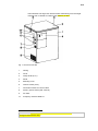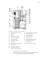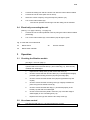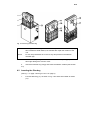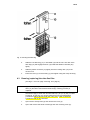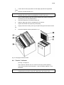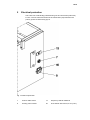
1
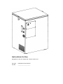
Instructions for Use
Designation of the unit: Single-user vacuum-cleaner unit
Unit type:
CERCON CLEAN 230VAC
Unit No.:
_____________________
2/15
Dear Customer:
Thank you for the confidence in our work that you showed us by buying this vacuumcleaner unit.
In order for you be able to enjoy your unit and its capabilities for many years, please take
the time to read these Instructions for Use carefully, especially before using the unit for
the first time.
Contents
1
Safety
2
1.1
Proper use
2
1.2
Potential hazards
2
1.3
Authorized operators
2
1.4
Safety precautions at the deployment site
2
1.5
Conventions used for the safety instructions in these Instructions for Use
3
2
Powering Up
3
2.1
Unpacking the single-user vacuum-cleaner unit
3
2.2
Short description of the unit – Identification of components
3
2.3
Turning on the unit
5
2.4
Electrically connecting the unit
5
3
Operation
6
3.1
Checking the filtration module
6
3.2
Air volume control
6
3.3
Automatic turn-off and filter change indicator
6
4
Cleaning and maintenance
7
4.1
Replacing the filter bag
7
4.2
Inserting the filter bag
8
4.3
Cleaning (replacing) the ultra-fine filter
8
4.4
“Service” indicator
9
5
Electrical protection
10
6
Technical specifications
11
7
Warranty conditions
12
8
EU Declaration of Conformity
13
3/15
1
Safety
1.1
Proper use
The CERCON CLEAN single-user vacuum-cleaning unit is used in dental
laboratories for the removal of the dust generated when working with dustproducing machinery. It is not permitted to attempt to use this unit for the
removal of liquids.
This vacuum-cleaning unit is suitable for removing Category C dust as per
the requirements of the German employers mutual insurance associations
pursuant to DIN EN 60 335-269 (ZH 1/487).
Unauthorized changes and modifications are prohibited for safety reasons.
Compliance with the operation and service conditions laid down in these
Instructions for Use is mandatory.
Caution
This unit was not designed as a medical device. Its use on humans is not
permitted!
1.2 Potential hazards
-
Do not vacuum any sources of ignition and no flammable gases, fumes and
liquids.
-
Turn off the unit using the mains switch before any maintenance,
cleaning or repair work, and physically disconnect from mains (by
unplugging the mains cable).
-
Because the vacuumed dust can constitute a health hazard, care
must be taken and insure that the filter bag and the ultra-fine filter are
inserted correctly at all times and that they are undamaged.
-
Before accessing the electrical component of the unit, the unit must be
disconnected from mains.
1.3 Authorized operators
The person or entity responsible for the operation of the unit must provide
the operator with the Instructions for Use and ensure that the latter has read
and understood them. Not until this is ensured will the operator be permitted
to operate the unit.
1.4 Safety precautions at the deployment site
The air from the air outlet (45) must be allowed to exit unimpeded.
The distance from the air outlet to the next obstacle (e.g. wall, piece of
furniture) must be at least 10 cm.
The unit must only be used inside cabinets or small rooms if proper
ventilation is ensured. The ambient temperature must not exceed 25 °C.
Do not insert any foreign matter into the unit through the vent openings.
4/15
Danger
The unit is not suitable for use in rooms in which special conditions prevail
(e.g. a corrosive or explosive atmosphere).
1.5 Conventions used for the safety instructions in these
Instructions for Use
Note
Indicates a practical hint to the user or other particularly useful information.
Caution
Indicates a usage or mode of operation whose non-observance may result in
irregular operation, damage to the unit or other problems.
Danger
Indicates dangerous situations which may result in bodily injury.
2
Commissioning
2.1 Unpacking the single-user vacuum-cleaning unit
1.
Place the box on a level surface.
2.
Remove the outer packaging material.
3.
Push the packaging material always from the unit and seize the lower edge
of the unit.
4.
Two people must be present to lift the unit out of the box (weight
approximately 25 kg).
5.
Check to ensure that all components are present:
-
Documentation
-
Mains cable
-
Control cable
-
Vacuum hose, 40 mm in diameter, 2 m in length, with two 40-mm
connecting ducts
-
Single-use filter bags, paper, 5 ea.
2.2 Short description of the unit – Identification of components
The CERCON CLEAN single-user vacuum-cleaning unit features a powerful
noise-reduced high-capacity pressure fan and is equipped with an internal
potentiometer for regulating the amount of air, an automated power-off
function and a filter change indicator.
The vacuum-cleaning unit can be operated on any voltage between 200 and
240 V without any effect on the preset input air volume.
The CERCON CLEAN is used as a vacuum accessory for dental milling
units.
The vacuum function is turned on automatically as soon as the milling unit is
activated.
The dust is collected in a double-layer single-use filter bag made of paper.
The capacity of this filter bag can range up to 10 kg depending on the type of
5/15
dust collected. The large-area ultra-fine filter downstream from the singleuse filter bag is capable of holding back Category C dust 1.
Fig. 1: View from front left
1
Casing
2
Cover
3
Clamp locks (2 ea.)
4
Panel
5
Mounting cover
6
Thumb screws (2 ea.)
7
Connection socket for control cable
8
Primary power socket (230 V/50 Hz)
9
Air outlet
13
Frequency selector 50/60 Hz
1
As defined in: Sicherheitstechnisches Informations- und Arbeitsblatt der
Berufsgenossenschaft 510210
6/15
Fig. 2: Section through unit, viewed from the left
10
Plastic connector for filter bag
24
Sealing surfaces, circumferential
11
Filter bag
25
Seal, circumferential
12
Basket
26
Air intake opening
15
Duct, 63 mm in diameter
27
Air intake chamber
16
Duct, 40 mm in diameter
28
M6 nuts (2 ea.)
17
Cover for filter bag
29
Ledge with longitudinal bores
20
Pre-filtration chamber
30
Electrical wiring central
21
Floor rollers
31
Ultra-fine filter
22
Screws for bottom space (9 ea.)
32
Ultra-fine filtration chamber
23
Vacuum motor
2.3
Turning on the unit
(see Figs. 1 and 2 on page 4)
1.
Check the filtration module (see Section 3.1).
2.
Connect the 40-mm diameter hose to the milling unit (keeping the hose as
short as possible; the maximum length is approximately 2 m).
7/15
3.
Connect the milling unit and the vacuum unit with the control cable included.
4.
Connect the unit to mains (230 V/50 or 60 Hz).
5.
Select the correct frequency using the frequency selector (13).
6.
Turn on the mains switch (34).
-
The vacuum process will not begin until the milling unit is activated.
2.4 Electrically connecting the unit
(see Fig. 3 on page 5 and Fig. 7 on page 10)
1.
Connect the unit to mains (230V/50 or 60 Hz) using the mains cable included
(socket (8)).
2.
Turn on the mains switch (34). The indicator (35) will light in green.
Fig. 3: Panel with control elements
34
Mains switch
35
Mains switch indicator
3
36
Service indicator
Operation
3.1 Checking the filtration module
(see Figs. 1 and 2 on page 4)
Caution
The CERCON CLEAN single-user vacuum-cleaning unit must not be
operated without an ultra-fine filter (31) and a filter bag (11), both correctly
installed and undamaged.
1.
Open the two clamp locks (3) and remove the cover (2).
2.
Check to ensure that the ultra-fine filter (31) is undamaged and tightly
pressed against sealing surfaces (24) using the ledge (29).
3.
Check to ensure that the two M6 nuts (28) are tightened firmly and
equally.
4.
Check to ensure that the mounting cover (5) is tightly screwed into
place using the two thumb screws (6).
5.
Check to ensure that the filter bag (11) is inserted properly in the
basket (12) and that it is undamaged.
6.
Check to ensure that the plastic connector (10) of the filter bags is
seated tightly on the connecting duct (15).
7.
Replace the cover (2) and close the two clamp locks (3).
3.2 Air volume control
Note
The fuller the filter bag (11), the less powerful the vacuum.
8/15
Thanks to the built-on power stabilizer, the preset input air volume is kept
constant as the mains voltage changes (between 180 and 264 V).
3.3 Automatic turn-off and filter change indicator
(see Fig. 6 on page 9).
Note
As soon as the filter bags (11) has been filled to the maximum permissible,
an underpressure switch will actuate the automatic turn-off function, and the
filter change indicator on the milling unit will be lit. The vacuum will not be
turned off until the milling procedure is completed. The milling unit can only
be turned back on when the filter bag has been replaced or the ultra-fine
filter cleaned.
1.
Note
If the automatic turn-off function has turned off the unit, cycling the unit off
and on and tapping the filter bag (11) will allow the operator to keep working
for a little while longer without having to replace the filter bags.
2.
Note
4
The filter bag (11) has to be replaced, see Section 4.1.
To tap the filter bag (11), open the two clamp locks (3) and remove the cover
(2) (see Figs. 1 and 2 on page 4).
If the automatic turn-off function has turned off the unit (filter change
indicator is lit) and the filter bag (11) turns out not to be full, the ultra-fine
filter (31) must be checked (see Section 4.3).
Cleaning and maintenance
4.1 Replacing the filter bag
(see Figs. 1 and 2 on page 4 and Fig. 4 on page 7)
1.
Open the two clamp locks (3) and remove the cover (2).
2.
Use both hands to pull the plastic connector (10) off the duct (15).
3.
Close the filter bag (11) using the attached plastic cover (17).
4.
Carry the filter bag (11) to the designated disposal site within its basket (12)
and dispose of properly.
9/15
Fig. 4: Removing the filter bag
Caution
The single-use filter bags must never be emptied and reused. Not only might
this constitute a health hazard, but it would also impair the function of the
unit.
Caution
Do not use pressurized air to remove any dust present in the filtration
chamber (20).
Do not allow any foreign matter to enter the air intake opening (26) because
this might damage the vacuum motor.
5.
Insert the new filter bag snugly and check the filtration module (see Section
4.2).
4.2 Inserting the filter bag
(see Fig. 1 on page 4 and Figs. 6 and 7 on page 9)
1.
Fold new filter bag (11) as shown in Fig. 5 and insert into basket as shown
(12).
10/15
Fig. 5. Inserting the filter bag
4.3
2.
Slide the new filter bag (11) in its basket (12) into the unit. The duct of the
filter bag (10) will engage the duct (15) inside the filtration chamber (20)
tightly.
3.
Slide the plastic connector (10) tightly onto the housing duct (15) of the
vacuum unit.
4.
Place the cover (2) on the housing (1) and tighten using the clamp locks (3).
Cleaning (replacing) the ultra-fine filter
(see Figs. 1 and 2 on page 4 and Fig. 6 on page 9)
Note
Approximately every tenth time the filter bag (11) is changed, the ultra-fine
filter (31) should be removed and cleaned (dry cleaning process) or
replaced.
We will be happy to clean the ultra-fine filters (31) for you by way of a filter
exchange. In this way you can be certain that only type-tested filters
pursuant to DIN EN 60 335-2-69 (ZH 1/487 para. 2 with a certificate
pursuant to DIN 24184) are used.
1.
Open the two clamp locks (3) and remove the cover (2).
2.
Open and remove the thumb screws (6) and und mounting cover (5).
11/15
3.
Loosen the two nuts (28) and lift out the ledge (29) with the longitudinal
holes.
4.
Caution
Remove the ultra-fine filter (31).
No dust may be present on the sealing surfaces (24) or in the air intake
chamber (32), as the dust may damage the vacuum motor (23).
The air intake chamber (32) and sealing surfaces (24) must be cleaned by
vacuuming. Do not use pressurized air.
5.
Insert the cleaned or new ultra-fine filter (31).
6.
Slide the ledge (29) onto the threaded pins from above.
7.
Tighten the two M6 nuts (28) firmly and equally.
8.
(6).
Tightly screw the mounting cover (5) into place using the two thumb screws
9.
Check the filtration module (see Section 3.1).
Fig. 6: Changing the ultra-fine filter
4.4 “Service” indicator
(see Fig. 3 on page 5).
If the “Service” indicator is lit, the vacuum motor (23) needs replacing.
The vacuum motors must be checked – and if necessary replaced – by a
specialist.
Note
Follow the “CERCON CLEAN single-user vacuum-cleaner unit
troubleshooting checklist” during all maintenance and service work.
12/15
5
Electrical protection
The entire unit is electrically protected using two fine-wire fuses (main fuse)
6.3 A/T. The two fuses are located in the fuse drawer (40) inserted in the
primary power socket housing (8) ist.
Fig. 7: Electrical protection
7
Control cable socket
13
Frequency selector 50/60 Hz
8
Primary power socket
40
Fuse drawer with fuses 6,3 A/T (2 ea.)
13/15
6
Technical specifications
Designation of the unit
Single-user vacuum-cleaning unit
Unit type
CERCON CLEAN 230VAC
Dimensions
420 mm wide (including mains cable
relief), 390 mm deep (with vacuum
duct), 540 mm high
Voltage
200 + 240 Volt (50/60 Hz)
Overvoltage category
II
Power requirements
Max. 800 W
Air throughput
max. 40 l/s
Noise level
61 dB(A)
Vacuum duct connector
40 mm diameter
Dust uptake
Up to approximately 10 kg (depending
on the type of dust)
Electrical protection
2 × 6,3 A/T (mains connection)
Weight
ca. 25 kg
7
Warranty conditions
This unit complies with present-day safety requirements and has been tested
extensively before leaving the factory.
We offer you a 24-month warranty and undertake to perform, free of charge,
any repairs that may become necessary due to defects in material or
workmanship.
This warranty shall be void in the event that the repairs are not performed
either by ourselves or by an authorized reseller.
The provision of spare parts under this warranty does not extend the original
warranty period.
14/15
Normal wear and tear (brushes of the vacuum motor) or damage caused by
improper operation are not covered by this warranty.
To be able to offer you our comprehensive service, we ask you to return to
us the warranty slip (inserted in the front of these Instructions for Use) by fax
or mail.
Fax +49 7181 73139
Designation of the unit
Single-user vacuum -cleaner unit
Duplicate
Unit type
Warranty Slip
Unit No.
CERCON CLEAN 230 VAC
Date of purchase
DeguDent GmbH
Rodenbacher Chaussee 4
Postfach 1364
63403 Hanau
Germany
Reseller/depot
Sender
Date/Signature
8
EU Declaration of Conformity
pursuant to EC Machine Directive 98/37/EC
We declare that the machine described below conforms to the basic health and safety
requirements of the EC Directives in design and construction.
This declaration shall be void if the machine is subjected to any modifications not
authorized by us.
Manufacturer’s name
DeguDent GmbH
Manufacturer’s address Rodenbacher Chaussee 4, Postfach 1364, 63403 Hanau,
Germany
Designation of the unit
Single-user vacuum-cleaner unit
Unit type
CERCON CLEAN
The following EC directives were applied:
EC Machine Directive 98/37/EC
15/15
EC Directive for Electrical Equipment Designed for Use Within Certain Voltage Limits
(Low Voltage Directive) 73/23/EEC
EC Electromagnetic Compatibility Directive 89/336/EEC
The following harmonized standards were applied:
DIN EN 292
Sicherheit von Maschinen.
DIN EN 61 010-1
Safety requirements for electrical equipment for measurement,
control, and laboratory use
DIN EN 55 014
Funk-Entstörung von elektrischen Betriebsmitteln und Anlagen.
DIN EN 55 104
Elektromagnetische Verträglichkeit,
Störfestigkeitsanforderungen (Kategorie 1).
The following national technical standards were applied:
DIN EN 60335-2-69 (ZH 1/487) Einrichtung zum Abscheiden gesundheitsgefährlicher
Stäube mit Rückführung der Reinluft in die Arbeitsräume.
A Technical Documentation exists.
The Instructions for Use pertaining to the machine is present.
QC Manager
Hanau, 8 November 2001