1
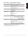
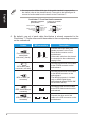
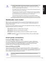
English
FrontLinker™
User Guide
Contents
English
Welcome...........................................................................................................2
Package contents.............................................................................................2
FrontLinker™ specifications summary..............................................................3
Device overview................................................................................................4
Device installation.............................................................................................5
USB standby power..........................................................................................7
Features............................................................................................................8
Magic cables usage..........................................................................................8
Multimedia card reader.....................................................................................9
Front panel connectors.....................................................................................9
FrontLinker™ DH panel board layout ............................................................10
Welcome
Thank you for choosing the ASUS FrontLinker™!
The ASUS FrontLinker™ is your convenient access to some of the most useful
computer ports. With the latest features in digital technology developed by
ASUS, the ASUS FrontLinker™ is sure to keep you ahead in the world of digital
computing!
Package contents
Check the following items in your ASUS FrontLinker™ package. Contact your
retailer if any item is damaged or missing.
ASUS FrontLinker™
User guide
MP3-In, USB 2.0, IEEE 1394a, Serial ATA, and Front Panel Audio cables .
(By default, these cables are plugged into the ASUS FrontLinker™)
Dimensions
Front panel I/O
148.5 x 42.8 x 121.1 mm
5.25-inch (CD-ROM Size Front Panel)
1 x USB 2.0
1 x IEEE 1394a (6-pin)
English
FrontLinker™ specifications summary
1 x External Serial ATA (E-SATA) port
Magic Cables
1 x Karaoke 6.3 mm mic port
1 x MP3-In cable
Card reader*
1 x miniUSB 2.0 cable
Compact Flash
1 x iPod® Dock cable
SmartMedia
Secure Digital (SD/mini SD)
MultiMedia Card
Memory Stick
Special features
Memory Stick Pro
Magic Charger™: Enables users to charge portable devices via
USB 2.0 cable without turning on the PC*
Magic Stereo™ (MP3-In cable): Enables users to playback
music via PC stereo speakers
without turning on the PC
Supported motherboards Supports all ASUS motherboards**
FrontLinker™ functions may vary depending on the available
connectors on the motherboard.
•Magic Charger™ feature supports all motherboards with
USB connectors.
• Magic Stereo™ feature supports all ASUS Digital Home
motherboards (except P5LD2-VM DH and N4L-VM DH).
* For some portable devices, you may need to turn on the PC to charge the battery.
** For some storage cards, you may need to purchase a separate adapter.
***Specifications are subject to change without notice.
Device overview
English
Front panel
Cable passage**
Card reader LED*
MS/All MS Pro Series
SM
CF
Cable access door
SD/MMC
1394a port
E-SATA port
USB 2.0 port
Karaoke 6.3 mm mic port
* The card reader LED blinks when reading/writing a storage card.
**You may put the Magic Cables through the cable passage while the cable access door is closed.
Magic Cables
MP3-In cable
iPod® Dock cable
miniUSB 2.0 cable
Device installation
English
To install the ASUS FrontLinker™:
1. Remove the cover of an empty 5.25”
drive bay.
We suggest installing the
FrontLinker™ into the upper drive
bay of the PC, not under the optical
drives.
2. Plug the 4-pin ATX power cable into
the ATX power connector on the
FrontLinker™.
3. Insert the FrontLinker™ to the drive bay.
Let all the cables pass inside the PC
case. Carefully push the FrontLinker™
until its screw holes align with the holes
on the drive bay.
4. Secure the FrontLinker™ with screws on
both sides of the drive bay.
We suggest that you place your portable devices on top of the chassis while
connecting to the FrontLinker™.
5. Two Front Panel Audio cables are connected to the FrontLinker™. The shorter one
should be connected with the audio cable from the chassis. For the connection
of another Front Panel Audio cable, refer to step 6.
Cable
.
Front Panel Audio
cable (black
connector) (male)
Chassis connector
or
Description
Connect the shorter cable, with
male connector, to the audio cable
from the chassis.*.
If the audio cable from the chassis
is connected to the motherboard,
unplug it first.
English
* You may need to define which type of the audio standard is supported by
the chassis (refer to the chassis manual). Then refer to the below figure to
connect the audio cable from the chassis to the FrontLinker™.
FrontLinker™ Front Panel Audio connector
HD Audio-compliant
pin definition
SENSE2_RETUR
Legacy AC ‘97 audio
pin definition
PORT2 L
SENSE_SEND
PORT2 R
PORT1 R
PORT1 L
SENSE1_RETUR
PRESENCE#
GND
NC
NC
NC
AGND
Line out_L
NC
Line out_R
MICPWR
MIC2
6. By default, one end of each cable listed below is already connected to the
FrontLinker™. Plug the other end of these cables to the corresponding connectors
on the motherboard.
Cables
.
Front Panel Audio
cable (black
connector) (female)
MB connectors
AAFP
.
SATA cable (black
connector; red cable)
.
USB 2.0 cable (blue
connector)
FP_Audio
MP3IN
IE1394
USB56
or
Connect the longer cable, with
female connector, to the Front
Panel Audio connector on the
motherboard. .
If the audio cable from the chassis
is connected to the motherboard,
unplug it first.
Connect the other end of this cable
to the E-SATA connector on the
motherboard.
SATA
.
MP3-In cable (red
connector)
.
IEEE 1394a cable (red
connector)
or
Description
USB78
Connect the other end of this cable
to the MP3IN connector on the
motherboard..
The MP3IN connector is included
only on ASUS Digital Home
motherboards (except P5LD2-VM
DH and N4L-VM DH).
Connect the other end of this cable
to the IEEE 1394a connector on the
motherboard.
Connect the other end of this
cable to the USB connector on the
motherboard.
•
•
•
Make sure the USB connector on the motherboard is set to +5VSB. You
may need to set up jumpers if your motherboard does not have auto-switch
function (refer to the motherboard manual). For detailed information about
jumper settings, refer to the section “USB standby power”.
We suggest connecting the SATA cable to the E-SATA connector on the
motherboard (not any SATA connector); otherwise, the transfer rate may
be decreased. Refer to the motherboard manual for the location of E-SATA
connector.
Make sure that the cables are firmly connected on both ends.
When the PC is turned on, the power supply comes from ATX power cable;
when the PC is turned off, the power supply comes from +5VSB on the
USB connector.
English
•
7. The blue LED indicator lights up when the power cable from the power outlet is
connected to the PC, the USB cable is correctly connected to the motherboard, and
the USB connector on the motherboard is set to +5VSB. For the location of the blue
LED indicator, refer to the “FrontLinker™ DH panel board layout” on page 10.
Don’t forget to connect the power cable from the power outlet to the PC.
USB standby power
PVD-MX
If your motherboard does not have auto-switch function (refer to the motherboard
manual), you may need to set up jumpers. .
You may find a number of jumpers labelled “USBPW” on your motherboard. The
USBPW12 and USBPW34 jumpers are for the USB ports on the rear panel. The
USBPW56 and USBPW78 jumpers are for the internal USB connnectors that
you can connect to additional USB ports. You only need to set up USBPW56
and USBPW78 for using the FrontLinker™. If the jumper of the USB is not set to
+5VSB position, refer to your motherboard manual to set the jumper to +5VSB
position. Here we take ASUS P5VD2-MX motherboard an example:
ex:
USBPW12
USBPW34
3
2
2
1
+5V
(Default)
®
1 2
PVD-MX USB device wake-up
•
•
+5VSB
USBPW56
USBPW782
+5V
(Default)
3
+5VSB
The total current consumed must NOT exceed the power supply capability
(+5VSB) whether the PC is turned on or off. Overloading the current
consumed when the PC is turned off may result in startup failure.
We suggest charging no more than two devices at the same time when the
PC is turned off.
Features
English
Magic Charger™
ASUS FrontLinker™ is designed with Magic Cables that allow you to
charge your portable devices such as mobile phones, PDAs, and MP3
players with ease. You can charge your devices without turning on the
PC!
Magic Stereo™
ASUS FrontLinker™ allows you to playback music from devices connected
to MP3-In cable via PC stereo speakers. Furthermore, you can enjoy
listening to your music when the PC is turned off. To do so, simply plug the
Magic cables into the corresponding ports on your portable device and turn
on the speaker. Then you can play your portable device as usual.
Magic cables usage
The length of the Magic Cables is retractable. You can set the cable length you
want by pulling out the cable to the desired distance. Pull out the cables to the end
and release slowly to retrieve the cables.
Magic Cable for miniUSB
The Magic Cable for miniUSB allows you to charge the battery of your portable
device or download/upload files between the PC and your portable device.
Simply connect the cable to the miniUSB port of your portable device. When
charging the battery, you may turn off the PC. For file transfers, both PC and
your portable device should be turned on.
Magic Cable for Apple® iPod®
The Magic Cable for iPod® allows you to charge your iPod® battery, and
download/upload files between the PC and iPod®. Simply plug the cable
into the corresponding port on your iPod® to start using the function. For file
transfers and battery charging, both PC and your iPod® should be turned on.
Magic Cable for MP3-In
The Magic Cable for MP3-In allows you to playback the music files stored in
your portable devices by using the PC stereo as the output. Simply plug the
cable into the audio-out port on your portable device to start using the function.
Hold the cable header and pull out the cable to the end, then release
SLOWLY to retrieve the Magic Cables. Do not release the cables quickly,
doing so might damage the FrontLinker™.
•
We suggest leaving the cable access door open while pulling/releasing the
cables to avoid the risk of a cable jam.
•
The total current consumed must NOT exceed the power supply capability
(+5VSB) whether the PC is turned on or off. We suggest charging no more
than two devices at the same time when the PC is turned off.
•
Use this product according to instructions in the user guide. Product
warranty or service does not cover damage resulting from incorrect usage.
English
•
Multimedia card reader
With the card reader placed on the front panel of the computer case, users are
able to read and save data easily. You no longer need to waste desk space for
external card readers.
Follow the information below to insert cards to the specified card slots. Look at the
label beside each card slot for reference.
CF card slot: Supports Compact Flash (CF) card.
SM card slot: Supports Smart Media card (SM).
MS card slot: Supports Memory Stick and all Memory Stick Pro series.
SD/MMC card slot: Supports Secure Digital (SD/mini SD) and Multi-media
card.
Front panel connectors
Front panel IEEE 1394a port (1394)
The front-loaded IEEE 1394a port is more convenient for users, allowing you
to connect to video devices, storage peripherals, or portable devices in 1394a
interface easily. Make sure IEEE 1394a cable is connected to the IE1394a
connector on your motherboard before using the function.
External SATA port (E-SATA)
The front-accessed E-SATA port, supporting Serial ATA 1.5 Gb/s and Serial
ATA II 3.0 Gb/s devices, enables users to connect to an external SATA box with
ease. Ensure that SATA cable is connected to the external SATA connector on
your motherboard before using this function.
The distance between the E-SATA port and your SATA device should not
exceed 1.5 m.
USB 2.0 port
English
The front panel USB port enables users to transfer files and charge devices
with ease. Ensure the USB 2.0 cable is connected to USB connector on your
motherboard before using the function. You can charge your device at anytime
whether the PC is turned on or off.
Karaoke 6.3 mm microphone port
The front-loaded karaoke microphone port is convenient for sound input and sound
recordings. Ensure the Front Panel Audio cable is connected to the Front Panel
Audio connector on your motherboard before using the function.
The karaoke 6.3 mm microphone port on the FrontLinker™ and the microphone
port on the chassis share the same Front Panel Audio connector on the
motherboard. Using the two ports simultaneously may result in overdubbing or
other unexpected effects. Therefore, we strongly suggest not plugging in the
two ports at the same time.
FrontLinker™ DH panel board layout
1
2
3
4
5
6
7
8
12 11 10 9
1. E-SATA connector
2. IEEE 1394a connector
10
7. Front Panel Audio connector
(connected to motherboard)
3. ATX Power connector
8. MP3-In connector
5. Standby Power LED blue indicator
10.Magic Cable for iPod® connector
4. USB 2.0 connector
9. Magic Cable for miniUSB connector
6. Front Panel Audio connector
(connected to chassis)
11.Card reader connector
12.Magic Cable for MP3-In connector