1
OWNERS MANUAL
Models: BASS1·V1
BASS2·V1
Congratulations on purchasing your VIBE
BASS amplifier, please read this manual in
order to fully understand how to get the
best results from your amplifier and
ensure that all advice on how to look after
the amplifier is followed.
Thank you for buying VIBE, we hope you
enjoy listening to your product as much as
we enjoyed creating it.
VISE R&D Division
Attention
An aftermarket audio amplifier will place an additional load on the vehicles charging system, most
modern vehicles have sufficient capacity in the charging system as not all the electrical
components of the vehicle will be switched on at once, Check the fuse rating of the amplifier and
use this as the peak current requirement, generally the continuous current draw will be a third of
the peak current, in other words an amplifier fused at 30 amps will have a continuous current
draw of 10 amps when playing music, however it may peak at 30 amps on occasions, Please
check with the manufacturer as to whether your vehicle can cope with the additional load of your
amplifier, in some instances it may be necessary to upgrade the alternator and battery or risk
damage to the vehicles electrical system,
Warning
During the normal use of this amplifier the heat sink may become very hot
please do not touch during or immediately after use
Mounting Guidelines
Your VIBE amplifier is designed with a swift installation routine in mind. Please mount the amplifier in a dry location on a solid
surface. NEVER mount the amplifier upside down, this will cause the amplifier to over heat and will eventually damage the
amplifier. Before fixing the amplifier in place please ensure that there is sufficient air flow around the exterior of the casing,
at least two inches is sufficient.
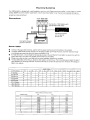
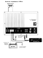
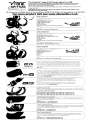
Connections
+12V REM GND
Connect to + 12Vof battery with
appropriate FUSE value.
,
.
I)'
•
. "m
- .
............
~.1lI'
Connect to remote
turn-on lead of
source unit.
Connect to chassis
ground of vehicle"
BATIERY
+
Power Cable
•
•
•
•
•
At least an 8 gauge cable should be used for both the power and the ground connections to the amplifier.
The power cable should be taken directly from the battery. Rubber grommets should be used when passing through
any bulkheads to prevent the cable from becoming chaffed or cut.
It is vital that a fuse / circuit breaker (of at least equal value to the one fitted on the amplifier) is placed inline with the
power cable and is no further than eighteen inches away from the battery.
Please ensure that the fuse is not fitted until the entire installation procedure is complete.
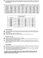
The two tables below are to help you decide on what cable is correct for you. The first enables you to select the size of
cable depending on the length required. The second will help you convert the cable size from American Wire Gauge to
Metric if you need to.
Lenqth of Run
Current demand
0- 4 Ft
4 - 7 Ft
7 - 10Ft
10-13Ft
13-16Ft
16-19Ft
19-22Ft
0-20 amps
14
12
12
10
10
8
8
8
20-35 amps
12
10
8
8
6
6
6
4
35-50 amps
10
8
8
6
4
4
4
4
50-65 amos
8
8
6
4
4
4
4
2
65-85 amps
6
6
4
4
2
2
2
0
85-105 amps
6
6
2
2
2
0
4
4
4
4
2
105-125 amps
2
0
0
0
0
125-150 amps
2
2
2
0
0
0
0
0
AWG Number
0
1
2
3
4
5
6
7
8
9
10
AWG to Metric Conversion Chart
cross sectional area
Inch
mm
0.325
0289
0.258
0.229
0.204
0.182
0.162
0.144
0.128
0.114
0.102
825
7.35
6.54
5.83
5.19
4.62
4.11
366
3.26
2.91
2.59
mm 2
53.5
42.4
33.6
26.7
21.1
16.8
13.3
10.5
8.36
6.63
5.26
22 - 28 Ft
Ground Cable
•
•
•.
•
The
The
The
It is
ground cable needs to carry the same current as the power cable. At least an 8 gauge cable should be used.
amplifier ground should be connected directly to the chassis of the vehicle. to bare metal.
cable length should be kept to an absolute minimum.
not recommended that you connect the ground cable to the vehicles seat belts anchor point.
Remote Turn On
•
•
•
A minimum of 18 gauge cable should be used for this connection.
The cable should be run with exactly the same care and attention as the power cable and taken back to the source
(headunit) and joined to the remote cable provided.
If the source (headunit) does not have a remote turn on cable then a 12v supply should be used. This will require a
switch to be fitted inline to enable the amplifier to be turned on and off. Remember that if this switch is left on you will
flatten the car battery.
RCA Cables
•
•
•
Depending on the model number of your amplifier and the number of speakers you wish to power you will have to run
either one or two RCA cables from the source to the amplifier.
Please take extra care when running these cables from the source to the amplifier. Ensure that they are placed away
from all items that can generate any interference, wiring harnesses etc.
It is recommended that the RCA cables should be run on opposite sides of the car to the previously installed power
cables if possible, to avoid the cable picking up interferance.
For optimal performance VIBE recommends using only VIBE Critical link cable and
connectors using any thing less can seriously compromise the performance of your
amplifier. see back page fo details
@
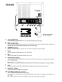
1.
LOlN Level Input
Connect the left and right RCA leads from your source (CD Player) to these terminals.
2.
High Level Input
If your source does not support RCA outputs connect the speaker outputs to the amplifier using the high level input
terminals. This must not be used at the same time as the low level inputs.
:3.
XOVER Frequency Hz
Adjust the crossover frequency using this knob. The frequency ranges from 40Hz to 200Hz
4
PheBe
Switch for adjusting the phase between 0 and 180 degrees
5
Gain
Adjust the gain range of the amplifier between 0.25v and 6v
S
Remote Control Outlet
Connect the optional BBR10 VI BE remote gain control here. This is used to adjust the output levels of the amplifier from the
front of the car.
7
Remote Controll
(BBR10 OPTIONAL) Allows you to adjust the frequency and the gain from the front of the car.
B
Fuse
Standard blade fuse to protect the amplifier. Always replace this with one of the same value.
9
25x1
Sub\Noofer Output
Use this to connect the amplifier to the subwoofer
10
PO\NerlRemotBlGround terminals
+12V - connect to the positive feed from the battery.
Rem - Connect the remote output from the source (CD player) to this terminal. The voltage must be between 7V and 15V DC.
GND - The ground terminal to earth the amplifier. Connect this to the chassis of the vehicle.
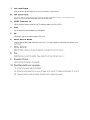
Minimum impedance 4
Ohm
@
Connect to + 12V
of battery with
appropriate
FUSE value.
Connect to chassis
ground of vehicle'
+
BATTERY
Connect to remote
turn-on lead of
source unit.
EI~SS
@
@
@
@
©
6 ~ ::=tlo~m ~':XiiVBr
"1:1 III!IIIII
D., le!'Ile!'Il~1
!J1;lLk I:m
1111II(
.12V
• REM'
GND
n. «(
.
-"'" -
"
'e".VV" e'
.•..
10
....'
EI
,e, ,e,eoe m,
~
@
"Aa~.
,....
,r,
@
@
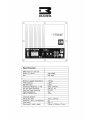
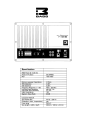
Specification
RMS Power @ 13.8v DC
Power @ 4 Ohms
Max
300WRMS
600 watts
Minimum speaker impendence
TH D Distortion
1M D Distortion
Frequency Response +/- 1dB
low level Input Sensitivity
High level Input Sensitivity
Input Impendence
Signal to Noise Ratio
4 Ohms
0.08%
0.08%
40Hz - 200 Khz
200 mV - 6V
2V-20V
15K
90 dB
Crossover Network
Sub-woofer filter
Protection ( short, temperature)
Fuse ratinq
Size lenght x width x depth
40 Hz - 200 Hz
yes
25A x 1
230mm x 195mm x 53 mm
••
EI~SS
@
@
@
@
@
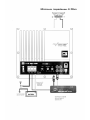
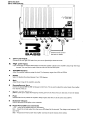
1.
Law- Level Input
Connect the left and right RCA leads from your source (CD Player) to these terminals.
2.
High Level Input
If your source does not support RCA outputs connect the speaker outputs to the amplifier using the high level input
terminals. This must not be used at the same time as the low level inputs.
3.
XOVER Frequency Hz
Adjust the crossover frequency using this knob. The frequency ranges from 40Hz to 200Hz
4
Phese
Switch for adjusting the phase between 0 and 180 degrees
5
Gein
Adjust the gain range of the amplifier using this
6
Remote Control Outlet
Connect the optional BBR10 VISE remote gain control here. This is used to adjust the output levels of the amplifier from the
front of the car.
7
Remote Cantrall
(BBR10 OPTIONAL) Allows you to adjust the frequency and the gain from the front of the car.
B
Fuse
Standard blade fuse to protect the amplifier. Always replace thiS with one of the same value. 30A X 2
9
Sub\Naafer Output
Use this to connect the amplifier to the subwoofer
., 0
Pa\NerlRematelGraund terminels
+12V - connect to the positive feed from the battery.
Rem - Connect the remote output from the source (CD player) to this terminal. The Voltage must be between 7V and 15V DC.
GND - The ground terminal to earth the amplifier. Connect this to the chassis of the vehicle.
Minimum impedance 4 Ohm
1!CE
.12V
REM
!II:1Lkl:m
OND
SS 1.1.1.'
l~i~i~1
;.:
BASS 2
..
'.'"
,',
:.:
~:,
-@-----f:i;-!--t--
~
e
~)
I, '!rtJ!riJl
00
llOVER FR£OI1.
PHAse
~
(~i:0
aa[]
aa~ :
•
Y
~
=3I1osr~
ImXiiVBr
----=----;-@:----~-li"iIPr_--------@-
'f
~~;y!~~~t~~Tote
~@
.'~\.
if;
~~
'if<.
j.~
c~~~r~~~~v~ pt
- BATTERY
:'i;,;;.:. ,
1"""'1
+I
connec~to
chassis
, g r o u n d of vehicle*
...
,.111,
FU.... ~
.
,I 1 . , " . .
lJ
~.: l i
~
/1l1li( . , .
,..'"
"
1.,_"'''-
n._.
.
. . . .,
,,"
!3
BASS
Specification
RMS Power @ 13.8v DC
Power @ 4 Ohms
Max
600WRMS
1200 watts
Minimum speaker impendence
THD Distortion
IMD Distortion
Frequency Response +/- 1dB
low level Input Sensitivity
High level Input Sensitivity
Input Impendence
Signal to Noise Ratio
4 Ohms
0.08%
0.08%
40Hz - 200 Khz
200 mV - 6V
2V- 20V
15K
90 dB
Crossover Network
Sub-woofer filter
Protection ( short, temperature)
Fuse ratinq
Size lenght x width x depth
40 Hz - 200 Hz
ves
30A x 2
230mm x 195mm x 53 mm
Set Up Section
To correctly set the gain control of the amplifier to match that of the source [headunit] use the following setup routine:
•
•
•
•
•
Turn the gain control to minimum on the amplifier.
Ensure the bass boost is set to 0 dB.
On the headunit set all crossovers (if applicable] to flat and both bass and treble to zero.
Turn up the source (headunit] to approx 3/4 volume.
Very slowly turn up the gain on the amplifier until distortion can be heard in any of the speakers or until the volume
reaches an uncomfortable listening level when this is reached turn down the gain control slightly.
The gain contorol is now Beto.
The setting of the crossover will depend on what kind of speaker you are installing.
For a subwoofer it is recommended that the crossover frequency is set to match that of the subwoofers specifications, or
your preferred frequency - this is usally about 60 Hz - 120 Hz
Not:e:
By using the crossovers correctly you will not only lengthen the life of your speakers but you will also get better performance
from them. To optimise your setup seek the advise of a professional installation engineer or visit your local VIBE audio dealer
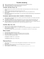
Trouble shooting
•
•
•
Before removing the amplifier, refer to the list below and follow the suggested procedures.
Always test the speakers and confirm that they are wired correctly first.
If in any doubt get help from a qualified auto electrician.
Amplifier Will Not PO\Ner Up
,/
,/
,/
,/
,/
Check for good ground connections. Ensure Ground cable is connected directly to bare metal and not a painted
surface.
Using a multimeter check that remote terminal has at least 7V DC.
Using a multimeter check that there is battery voltage of at least 10.5v DC on the positive terminal.
Check all fuses.
Check that the protection light is not illuminated. If it is lit, shut off the amplifier by disconnecting for thirty seconds and
then turning it back on.
Protection LED Illuminates When Amplifier Is PO\Nered Up
,/
•
•
Check for shorts on all speakers wires. (i.e. no speaker wires should be jOined together and no speaker wires should
be touching the cars chassis)
The amplifier is designed to shut down automatically when the units temperature goes above 80 degrees. If the
amplifier feels very hot then this may be the reason for the amplifier not starting. Allow to cool down try again.
Remove the speaker wires and reset the amplifier. If the Protection LED still comes on then the amplifier is faulty. This
damage may have been caused by either failure to follow these setup gUidelines or abuse.
Amplifier Gets Very Hot
,/
,/
.I
Check the minimum speaker impedance for the amplifier [s correct.
Check for shorts on all speakers wires. (i.e. no speaker wires should be joined together and no speaker wires should
be touching the cars chassis)
Check that there is good airflow around the amplifier. In some applications an external fan may be required.
Blo\Nn Fuee[s]
,/
,/
,/
.I
Check both positive supply and ground for shorts.
Check that the positive wire is connected to the positive terminal on the amplifier.
Check that the negative wire is connected to the ground terminal on the amplifier.
Ensure that the correct rated fuse IS fitted:
The VIBE Bass 1 amplifier uses 1 x 25 amp fuse
The VIBE Bass 2 amplifier uses 2 x 30 amp fuse
Distorted Sound
,/
.I
.I
,/
Check the gain control is not set too high. If the speakers sound distorted turn down the gain until the
sound is clear.
Check that all crossover frequencies are correct. See Setup section for more details.
Check for shorts on all speaker wires.
Check all speakers are wired correctly. With the correct polarity being observed on each connection.
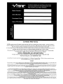
Limited Warranty
All VISE products carry a full twelve months warranty. valid from the date of the original receipt / proof of purchase. In
order to validate this warranty. the warranty card should be returned to VISE within seven days of the original purchase
date. The original receipt and packaging should also be retained for this twelve month period.
If at any stage during the warranty period you have a problem with the product then it should be returned to the point of
purchase, with proof of purchase in its original packaging. complete with no items missing.
If the store is unable to fix the product it may have to be returned to VISE this process takes around 7 working days.
A full description of VISE's warranty information can be found on our website:
.WWw.vibeaudia.ca.uklwarranty
A written version can also be obtained from VISE warranty Dept. PO SOX 11000. S75 7WG
Technical enquires call 09067031420
call cost 50p per minute call costs correct at date of publication (01/11/06JHours of business 9.00am - 5.30pm all calls are recorded for training
purposes MIDBASS Distribution, PO Box 11000, B75 7WG
Copyright
All content included in this manual such as text, graphics. logos. icons, images and data, are the property of VIBE Technologies Lknited (herein referred to as "VIBE~. ·us· or "we-) and its affiliate or their
content and technology providers, and are protected by United Kingdom and Intemational copyrighllaws. All rights reserved.2007
All stylised representations of product names, or the abbreviations of product names, as k>gos are all trademarks of VISE. Graphics and logos are trademarks or trade dress of VISE Technologies Ltd or
its subsidiaries.
VISE's trademarks and trade dress may not be used in connection with any product or service that is not VISE's, in any manner that is likely to cause confusion among customers or in any manner that
disparages or discredits VISE. AJI other trademarks not owned by VIBE or its subsidiaries that appear in this manual are the property of their respective owners, who mayor may not be affiliated with,
connected to, or sponsored by VI BE or its subsidiaries.
TO THE FULLEST EXTENT PERMITIED AT LAW. VIBE IS PROVIDING THIS MANUAL AND ITS CONTENT ON AN "AS IS" BASIS AND MAKES NO (AND EXPRESSLY DISCLAIMS ALL)
REPRESENTATIONS OR WARRANTIES OF ANY KIND. EXPRESS OR IMPLIED. WITH RESPECT TO THIS MANUAL OR THE INFORMATION, CONTENT. MATERIALS OR PRODUCTS INCLUDED
IN THIS MANUAL INCLUDING. WITHOUT LIMITATION. WARRANTIES OF MERCHANTABILITY AND FITNESS FOR A PARTICUlAR PURPOSE.
IN ADDITION. VIBE DOES NOT REPRESENT OR WARRANT THAT THE INFORMATION CONTAINED IN THIS MANUAL IS COMPLETE OR CURRENT. AND THAT ALL SPECIFICATIONS AND
INFORMATION CONTAINED WITHIN THIS MANUAL ARE SUBJECT TO CHANGE WITHOUT NOTICE.
VI BE RECOMMEND CAUTION WHEN LISTENING TO MUSIC REPRODUCED THROUGH VIBE EQUIPMENT. VIBE EQUIPMENT IS CAPABLE OF PRODUCING SOUND AND SOUND PRESSURE
LEVELS THAT CAN PERMANENTLY DAMAGE HEARING OF YOU AND THAT OF OTHERS. FOR SAFE AND ENJOYABLE LISTENING. THE SOUND SHOULD BE CLEAR WITHOUT DISTORTION
AT A COMFORTABLE VOLUME.
BY USING ANY VIBE EQUIPMENT. YOU AGREE TO TAKE FULL RESPONSIBILITY FOR YOUR OWN SAFETY AND THE SAFETY OF OTHERS WHEN LISTENING TO MUSIC AT HIGH VOLUMES
THROUGH EQUIPMENT YOU HAVE PURCHASED. USE OF ANY VIBE EQUIPMENT CONSTITUTES AGREEMENT TO THIS DISCLAIMER.
Except as specifically stated in lhis manual, to the fullest extent permitted at law, neither VISE nor any of its affiliates, directors, employees or other representatives will be liable for damages arising out of
or in connection with the use of this manual or the information, content, materials or products included.
This is a comprehensive limitation of liability that applies to all damages of any kind, including (without limitation) compensatory, direct, indirect or consequential damages, loss of data, income or profit,
loss of or damage to property and claims of third parties. For the avoidance of doubt, VISE does not limit its liability for death or personal injury to the extent only that it arises as a result of negligence of
VISE, its affiliates, directors, employees or other representatives.
_
F\.Jl~'3
... ,.a
...
.
_
-
RAT y 2f RCA I f _
RAT If 2M
r-
""",1"
!'CAV..,,_"',.....
......
I _IleA V1NlI'-""
MoooII ~1"""
_-=ID __
..-_aIll
,
"
"
~
--.
'-"'-~
MocIII
PP:JO
\lISE I;IIIl'1ooIl
... _ _ ............
~/aPZ!\ t~ ...
~" . .
I~'"
:r
"'Ii 101._
_.'-orIiIl.....
~
V'IllEpo-...,_ • • _a4W1E
' - .... _
Mrs .... I ~ - . _
VIllE "'""" fOgO" .....
'KD
W1Ecn-..._WIE
...
MJ::: VIllE 00 _
....-c _ CD _ _ VIllE.
VR
'ITO
_
Vft~_
Vft"~I_
~1Oo'
~!105
_W'II"'_llJr(I'r~
_ ..
_,~
1o&C11J/CT4=._
"'"
"'14
•
s..T...... _ ... ~
.". __ " ........
_...
.......-..VlIlElDQI:t.
.........
"'mg~
.;W.... ....._
p
4
_
_."
..
~
"'
..
cr-..
I _30
,
eo
,
1OAlJ.J
'Y'9~
_ _ PloC_
f'I'Ig
.,P\,(; _
1tQ.J "-I<I~.A(J.J""~
AClJ
t411L
A(J.J
"" ...
~
For more product: info !iee www.vibeaudio.co.uk
'"'Y1!3
5L
CRITICAl:
I6IlIN!JI¥1:
_--_
___----_.
_....._--__
_._.. _-_...-.._--_
-----_
__,,---_._--_--_
__................__ "..
....Th. em_'Unk'"
..
~..-.-
H:m-y
.... _
. . _ _ .... _
....
.
of FLAT
___A
_ _bllng _
VIIiiIE
....
. . . _ ~ ~ _.. _
...._
...
_._~
..
_
........
._
.....
... - .
For more produrt inf"D see www.vlbeaudlo.I:D.uk
BASS SYSTEM KIT
.......~-----.....
OU'108·_"
-,..,
. ........
......
.
-, ......
_""'
'
'
'
_
.. _......_-----_-.--_._---...._--_..
.........
_----_
.............
...........
_'.
,---STEFEO SVSTEM KIT
....
..---"
""" """'_Ou
ACTIVE SYSTEM KIT
....
a.
- ==:::
. . • . ,., ..? -
. .OTU'.. _
.,
wowoo ...
PC'S
~PWGI
...._ _ ... -...e-
--_
_
-_
_-_.......--.. _-_. _
-"'-_
••n
"
_
"".,
........t
' ."'"'
_
.....
--~
-_
..----_....._---- - --.... ,
--~
....""""
------
•••_
, .. r
OWNERS MANUAL
Congratulations on purchasing your VIBE CBR EVa subwoofer enclosure, please read
this manual in order to fully understand how to get the best results from your
enclosure and ensure that all advice on how to look after the enclosure is followed.
Thank you for buying VIBE, we hope you enjoy listening to your product as
much as we enjoyed creating it.
VIBE R&D Division
Attention
An aftermarket audio amplifier will place an additional load on the vehicles charging system, most
modern vehicles have sufficient capacity in the charging system as not all the electrical
components of the vehicle will be switched on at once. Check the fuse rating of the amplifier and
use this as the peak current requirement, generally the continuous current draw will be a third of
the peak current, in other words an amplifier fused at 30 amps will have a continuous current
draw of 10 amps when playing music, however it may peak at 30 amps on occasions. Please
check with the manufacturer as to whether your vehicle can cope with the additional load of your
amplifier, in some instances it may be necessary to upgrade the alternator and battery or risk
damage to the vehicles electrical system.
Warning
During the normal use of this amplifier the heat sink may become very hot
please do not touch during or immediately after use
Run in procedure
VISE recommends that you follow the run in procedure for the subwoofer detailed below.
•
When your Subwoofer is used for the first time naturally like most brand new items it is very stiff and rigid, it will take
time for the moving parts of this Subwoofer to loosen up before the Subwoofer will be ready to deliver its full potential.
•
For the first 30 hours it is recommended that you play the Subwoofer initially at low to medium volumes, gradually
increasing the volume level as time progresses.
•
As a guide, if you listen to your Subwoofer for 1 hour every day it will take a month for the speaker to run in properly.
•
You will notice a big change in the sound of the Subwoofer over this period. as the spider and surround begin to run in
the sound will get deeper and punchier, also the output of the Subwoofer will increase as the suspension loosens up.
•
The Subwoofer is like a new cars engine, it needs a few thousand miles before you can drive it to it's full potential,
driving it into the redline from the first day will mean engine damage is certain and will not be covered by warranty and
the same applies to the subwoofer
•
Failure to follow this simple procedure is the most common reason for a Subwoofer to fail after a very short period of
time.
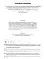
Installation
The most common place to mount a bass enclosure is in the luggage compartment of the vehicle.
Where in the luggage compartment it is mounted will have an effect on the sound produced allowing the user to tailor the
sound to best suit their musical tastes.
For example if the enclosure is mounted facing the rear bumper, the bass produced will be noticeably deeper than if it is
fired into the rear seat.
Do not be afraid to experiment with positioning as a little time and effort can yield great improvements in sound.
-
._------~~-_.-
!:-.,;.---- ~:::'c::-·::;;.::=.::.:I~
.,.. . . . . . . . . . . . . . _ _ ......... _ - ••
~-...._-
. . . . .& . . _ .
---.•~,.
NOTE - when you have chosen your mounting position please ensure that the enclosure is securely mounted in place
and cannot move or come into contact with objects in the luggage area as damage to the enclosure or subwoofer will not
be covered under warranty.
It is also advisable to use additional luggage straps to secure the enclosure.
Sealed or parted configurat;ion
Ported enclosures offer a significant increase in output compared to sealed enclosures, this is because the port in the
enclosure interacts with the air in the enclosure and the woofer to increase output and reduce cone movement around the
tuning frequency.
Ported enclosures are typically 2 or 3 times louder than seated enclosures and have a bump in the frequency response
making them the ideal choice for dance, R&B, electronically produced music and high SPL applications.
The CBR EVO enclosures are supplied with portplugs™. these give the user the option to use the enclosure as a sealed
enclosure.
Sealed enclosures are also known as acoustic suspension enclosures because the air in the box acts like a brake to control
the movement of the woofer cone.
Sealed enclosures offer high power handling, excellent transient response and smooth low end roll off making them the ideal
choice for live music, rock and jau.
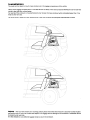
Variable part; tuning
CBR 12 EVO CBR 15 EVO, CBR 12 twin EVO only
CBR enclosures with 2 tUrboports™ offer the user variable port tuning options.
When both port plugs™ are removed the punch delivered by the enclosure will increase. ( fig.1 )
By removing 1 port plug™ the sound produced will increase in output and depth. ( fig.2 & 3)
With both port plugs™ installed the enclosure will act as a sealed enclosure. ( figA)
Do not be afraid to experiment as there are many different combinations as the top and bottom port will offer slightly
different characteristics.
Try sealed first, top portplug™ removed, refit the top portplug™ and remove the bottom portptug™, finally remove both port
plugs™ and see which variation is more suited to your musical taste.
fig . .,
fig.2
'lg.3
'ig.4
Upgrading CBR EVO
There are 2 upgrade options available for the CBR EVD passive enclosures
Active amplifier upgrade
The following enclosures can be upgraded with a VIBE Blackbox Bass series amplifier.
Not only will this increase convenience as both the enclosure and amplifier are one unit, but you can be sure that the
amplifier is perfectly matched to the subwoofers.
Product
Active amplifier
CBR 10 EVD
CBR12 EVD
CBR15 EVD
CBR 12 twin EVD
Blackbox Bass
Blackbox Bass
Blackbox Bass
Blackbox Bass
1
1
2
2
Space subwoofer upgrade
The CBR EVO enclosures can be upgraded with the VIBE Space reference SPL subwoofer
The Space subwoofer has a number of advantages over the Blackair subwoofer, the specification says it all,
* Double the power handling
* Aluminium cone
* High roll, long throw surround
* Double stacked magnet
* Dual 2 ohm or 4 ohm voice coil
The Space subwoofer will not only give huge gains in power handling but also sound quality, both punch and deep bass will be
significantly improved as well as a huge increase in overall output, basically more everything with better sonic quality.
NOTE - The Space &ubwoofer upgrade cannot be used in conjunction with the active amplifier
upgrade. only one upgrade can be made for information on compatible amplifers visit the website
listed below
FOR MORE INFORMATION ABOUT UPGRADES GOT TO WWWVlBEAUDID.CO.UK
Specification
Product
part no
RMS
peak
min input
CBR 10 passive
CBR10EVO-V2
450 Watts
1300 Watts
225 Watts RMS
40hm
CBR 10 active
CBR10AEVD-V2
450 Watts
1300 Watts
225 Watts RMS
40hm
CBR 12 passive
CBR 12EVD-V2
550 Watts
1600 Watts
275 Watts RMS
4 Ohm
CBR 12 active
CBR 12AEVD-V2
550 Watts
1600 Watts
275 Watts RMS
4 Ohm
CBR 15 passive
CBR15EVD-V2
650 Watts
2000 Watts
325 Watts RMS
4 Ohm
CBR 15 active
CBR1 5AEVD-V2
650 Watts
2000 Watts
325 Watts RMS
40hm
CBR 12 twin passive
CBR 12TEVD-V2
1100 Watts
3200 Watts
550 Watts RMS
2 x 2 Ohm
CBR 12 twin active
CBR12TAEVD-V2 1100 Watts
3200 Watts
550 Watts RMS
4,Ohm
impedance
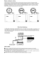
Passive enclosure wiring
The VISE enclosure terminals adds great detail to any bass enclosure and ease of connection. All new spring loaded
connectors replace the old screw down type for quicker and tighter clamping of speaker wire or VISE GP41 banana plugs.
The VISE QP4 QuadPost features 4 posts on one terminal and a NEW CNC alloy top. a rubber inner and outer rubber
sealing gasket - The Quad terminals come complete with the NEW VISE T-Bridge terminal link - allows fast and reliable
bridging of VISE terminals for easy connection to a mono amplifier.
...
4 Ohm
...
1 Ohm
Mounting Guidelines
Your VISE amplifier is designed with a swift installation routine in mind. Please mount the amplifier in a dry location on a solid
surface. NEVER mount the amplifier upside down, this will cause the amplifier to over heat and will eventually damage the
amplifier. Sefore fixing the amplifier in place please ensure that there is sufficient air flow around the exterior of the casing,
at least two inches is sufficient.
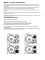
Connections
+12V REM GND
Connect to +12V of battery with
appropriate FUSE value.
Connect to remote
turn-on lead of
source unit.
Connect to chassis
ground of vehicle·
Power Cable
••
•
•
At least an 10 gauge cable should be used for both the power and the ground connections to the amplifier.
The power cable should be taken directly from the battery. Rubber grommets should be used when passing through
any bulkheads to prevent the cable from becoming chaffed or cut.
It is vital that a fuse / circuit breaker (of at least equal value to the one fitted on the amplifier) is placed inline with the
power cable and is no further than eighteen inches away from the battery.
Please ensure that the fuse is not fitted until the entire installation procedure is complete.
•
The two tables below are to help you decide on what cable is correct for you. The first enables you to select the size of
cable depending on the length required. The second will help you convert the cable size from American Wire Gauge to
Metric if you need to.
Lenath of RLln
Current demand
0-4Ft
4 - 7 Ft
7 - 10 Ft
10-13Ft
13 - 16 Ft
16-19Ft
19 - 22 Ft
0-20 amos
14AWG
12AWG
12AWG
10AWG
10AWG
8AWG
8AWG
BAWG
10AWG
8AWG
BAWG
6AWG
6AWG
6AWG
4AWG
22 - 28 Ft
20-35 amos
12AWG
35-50 amos
10AWG
BAWG
BAWG
6AWG
4AWG
4AWG
4AWG
4AWG
50-65 amos
BAWG
BAWG
6AWG
4AWG
4AWG
4AWG
4AWG
2AWG
65-85 amos
6AWG
6AWG
4AWG
4AWG
2AWG
2AWG
2AWG
OAWG
B5-105 amos
6AWG
6AWG
4AWG
2AWG
2AWG
2AWG
2AWG
OAWG
105-125 amos
4AWG
4AWG
4AWG
2AWG
OAWG
OAWG
OAWG
OAWG
125-150 amos
2AWG
2AWG
2AWG
OAWG
OAWG
OAWG
OAWG
OAWG
AWG Number
o AWG
1 AWG
2 AWG
3 AWG
4 AWG
5 AWG
6 AWG
7 AWG
8 AWG
9 AWG
10 AWG
AWG to Metric Conversion Chart
cross sectional area
Inch
mm
0.325
0.289
0.258
0.229
0.204
0.182
0.162
0.144
0128
0.114
0.102
8.25
7.35
6.54
5.B3
5.19
4.62
4.11
3.66
3.26
2.91
2.59
mm2
53.5
42.4
33.6
26.7
21.1
16.B
13.3
10.5
B.36
6.63
5.26
Ground Cable
•
•
•
•
••
•
The ground cable needs to carry the same current as the power cable. At least an 10 gauge cable should be used.
The amplifier ground should be connected directly to the chassis of the vehicle. to bare metal, remove paint with sand
paper if required.
The cable length should be kept to an absolute minimum.
It is not recommended that you connect the ground cable to the vehicles seat belts anchor point.
RemO'-B Turn On
A minimum of 18 gauge cable should be used for this connection.
The cable should be run with exactly the same care and attention as the power cable and taken back to the source
(headunit) and joined to the remote cable provided.
If the source (headunit) does not have a remote turn on cable then a 12v supply should be used. This will require a
switch to be fitted inline to enable the amplifier to be turned on and off. Remember that if this switch is left on you will
flatten the car battery.
RCA CablBs
•
•
•
Depending on the model number of your amplifier and the number of speakers you wish to power you will have to run
either one or two RCA cables from the source to the amplifier.
Please take extra care when running these cables from the source to the amplifier. Ensure that they are placed away
from all items that can generate any interference, wiring harnesses etc.
It is recommended that the RCA cables should be run on opposite sides of the car to the previously installed power
cables if possible, to avoid the cable picking up interferance.
For optimel performence VIBE recommende using only VIBE Criticel link cable end
connectors ueing any thing less cen seriously compromise ths performence of your
empllfler. see beck pege for details
@
@
@
CBR1D EVO ACTIVE
CBR12 EVO ACTIVE
optional remote control
see back for details
1.
Low Level Input
Connect the left and right RCA leads from your source (headunit) to these terminals.
2.
High Level Input
If your source does not support RCA outputs connect the speaker outputs to the amplifier using the high level input
terminals. This must not be used at the same time as the low level inputs.
3.
XOVER Frequency
Adjust the crossover frequency using this knob. The frequency ranges from 40Hz to 200Hz
4
Phase
Switch for adjusting the phase between 0 and 180 degrees
5
Gain
Adjust the gain range of the amplifier between 0.25v and 6v
6
Remote Control Port;
Connect the optional BBR1 0 VIBE remote gain control here. This is used to adjust the output levels of the amplifier
from the front of the car.
7
OptionsI Rsmote Control
(BBR10 )Allows you to adjust the frequency and the gain from the front of the car. See back of manual for details
B
Fuss
Standard blade fuse to protect the amplifier. Always replace this with one of the same value. 35A x 1
9
SublNoofer Output
Use this to connect the amplifier to the subwoofer
10
POlNerlRsmotelGround terminals
+ 12V - connect to the positive feed from the battery.
Rem..: Connect the remote output from the source (CD player) to this terminal. The voltage must be between 12V
and 15V DC.
GND - The ground terminal to earth the amplifier. Connect this to the chassis of the vehicle.
CBR15 EVO ACTIVE
CBR12lWIN EVO ACTIVE
r::@::---------------@-==O-----------@-=---O
••
E lA..SS
optional remote control
see back for details
1. ,Low Level Input:
Connect the left and right RCA leads from your source [headunit) to these terminals.
2.
High Level Input:
If your source does not support RCA outputs connect the speaker outputs to the amplifier using the high level input
terminals. This must not be used at the same time as the low level inputs.
3.
XOVER Frequency
Adjust the crossover frequency using this knob. The frequency ranges from 40Hz to 200Hz
4
Phase
Switch for adjusting the phase between 0 and 180 degrees
5
Geln
Adjust the gain range of the amplifier using this
6
Remote Control Port
Connect the optional BBR1 0 VIBE remote gain control here. This is used to adjust the output levels of the amplifier
from the front of the car.
7
Option Remote Control
[BBR10 ) Allows you to adjust the frequency and the gain from the front of the car. See back of manual for details.
B
Fuse
Standard blade fuse to protect the amplifier. Always replace this with one of the same value. 30A X 2
9
Subwoofer Output
Use this to connect the amplifier to thesubwoofer
10
PowerlRemotelGround terminals
+ 12V - connect to the positive feed from the battery.
Rem - Connect the remote output from the source [CD player) to this terminal. The voltage must be between 12V
and 15V DC.
GND - The ground terminal to earth the amplifier. Connect this to the chassis of the vehicle.
Mini",u", i",pedance 4 Dh",
@
@
@
@
@
@
Connect 10 remole
tum-onl••dof
,OUtceunit.
Set Up Section
To correctly set the gain control of the amplifier to match that of the source [head unit) use the following setup routine:
•
•
•
•
Turn the gain control to minimum on the amplifier.
On the headunit set all crossovers [if applicable I to flat and both bass and treble to zero.
Turn up the source [headunit) to approx 3/4 volume.
Very slowly turn up the gain on the amplifier until distortion can be heard or until the volume reaches an uncomfortable
listening level when this is reached turn down the gain control slightly.
The gain control is now set.
The setting of the crossover will depend on what kind of speaker you are installing.
For a subwoofer it is recommended that the crossover frequency is set to match that of the subwoofers specifications. or
your preferred frequency - this is usally about 60 Hz - 120 Hz
Note:
Sy using the crossovers correctly you will not only lengthen the life of your subwoofers but you will also get better
performance from them. To optimise your setup seek the advise of a professional installation engineer or visit your local
VISE audio dealer.
Trouble shooting
•
•
•
Before removing the amplifier, refer to the list below and follow the suggested procedures.
Always test the speakers and confirm that they are wired correctly first.
If in any doubt get help from your local VIBE dealer
Amplifier Will Not PO\Ner Up
•
•
•
•
•
Check for good ground connections. Ensure Ground cable is connected directly to bare metal and not a painted
surface.
Using a multimeter check that remote terminal has at least 12V DC.
Using a multimeter check that there is battery voltage of at least 1O.5v DC on the positive terminal.
Check atl fuses.
Check that the protection light is not illuminated. If it is lit. shut off the amplifier by disconnecting for thirty seconds and
then turning it back on.
Prot;ection LED Illuminates When Amplifier Is PO\Nered Up
•
•
•
Check for shorts on all speakers wires. (i.e. no speaker wires should be joined together and no speaker wires should
be touching the cars chassis]
The amplifier is designed to shut down automatically when the units temperature goes above 80 degrees. If the
amplifier feels very hot then this may be the reason for the amplifier not starting. Allow to cool down try again.
Remove the speaker wires and reset the amplifier. If the Protection LEO still comes on then the amplifier is damaged.
This damage may have been caused by either failure to follow these setup guidelines or abuse.
Amplifier Gets Very Hot;
•
•
•
Check the minimum speaker impedance for the amplifier is correct.
Check for shorts on all speakers wires. [i.e. no speaker wires should be joined together and no speaker wires should
be touching the cars chassis)
Check that there is good airflow around the amplifier. In some applications an external fan may be required.
Blown Fuse[s]
•
•
•
•
Check both positive supply and ground for shorts.
Check that the positive wire is connected to the positive terminal on the amplifier.
Check that the negative wire is connected to the ground terminal on the amplifier.
Ensure that the correct rated fuse is fitted:
The VIBE Bass 1 amplifier uses 1 x 35 amp fuse
The VIBE Bass 2 amplifier uses 2 x 30x amp fuse
Distort;ed Sound
•
•
•
•
Check the gain control is not set too high. If the subwoofer sounds distorted turn down the gain until the
sound is clear.
Check that all crossover frequencies are correct. See Setup section for more details.
Check for shorts on all speaker wires.
Check all speakers are wired correctly. With the correct polarity being observed on each connection.
Specification: VIBE BLACKBOX BASS 1
"
RMS Power @ 14.4v DC
Power @ 4 Ohms
Max
300WRMS
600 watts
Minimum speaker impedance
THO Distortion
IMD Distortion
Frequency Response +/- 1dB
low level Input Sensitivity
Hiqh level Inpu1 Sensitivity
Input Impendence
SiQnal to Noise Ratio
40hms
0.08%
0.08%
40Hz· 200 Khz
200 mV - 6V
2V- 20V
15K
90 dB
Crossover Network
Sub-woofer filter
Protection ( short. temperature)
Fuse ratinq
Size length x width x depth
40 Hz - 200 Hz
yes
35A x 1
230mm x 195mm x 53 mm
BASS
Specification: VIBE BLACKBOX BASS 2
••
RMS Power @ 14.4v DC
Power @ 4 Ohms
Max
600WRMS
1200 watts
Minimum speaker impedance
TH D Distortion
IMD Distortion
Frequency Response +/- 1dB
low level Input Sensitivity
Hiqh level Input Sensitivity
Input Impendence
Siqnal to Noise Ratio
4 Ohms
0.08%
0.08%
40Hz - 200 Khz
200 mV - 6V
2V- 20V
15K
90 dB
Crossover Network
Sub-woofer filter
Protection ( short, temperature)
Fuse rating
Size lengthx width x depth
40 Hz - 200 Hz
yes
30Ax 2
230mm x 195mm x 53 mm
B ASS
Limited Warranty
All VIBE products carry a full twelve months warranty, valid from the date of the original receipt / proof of purchase. In
order to validate this warranty. the warranty card should be returned to VIBE within seven days of the original purchase
date. The original receipt and packaging should also be retained for this twelve month period.
If at any stage during the warranty period you have a problem with the product then it should be returned to the point of
purchase, with proof of purchase in its original packaging, complete with no items missing.
If the store is unable to fix the product it may have to be returned to VIBE this process takes around 7 working days.
A full description of VIBE's warranty information can be found on our website:
WlNW. vibeaudiD .CD. uk/warranty
A written version can also be obtained from
VIBE warranty Dept. PO BOX 11000. B75 7WG
Technical enquires
call 09067031420
call cost 50p per minute Call costs correct at date of publication [02/02/08) Hours of business 9.o0am - 5.30pm all calls are recorded for training
purposes MIDBASS Distribution PO Box 11 DOO,B75 7WG
Copyright
All content included in this manual such as text. graphics, logos, icons. images and data. are the property of VISE Technologies limited (herein referred to as -VISE-, ·us· or '"we-) and Ks affiliate or
their content and technology providers, and are protected by Un~ed Kingdom and International copyright laws. All rights reserved.2008
All stytised representations of product names, or the abbreviations of product names, as logos are all trademarks of VISE. Graphics and logos are trademarks or trade dress of VISE Technologies
Ltd or its subsidiaries.
VISE's trademarks and trade dress may not be used in connection with any product or service that is not VIBE's, in any manner that is likely to cause confusion among customers or in any manner
the property of their respective owners, who mayor may not be affiliated
that disparages or disCled~s VIBE. All other trademarks not owned by VIBE or ~ subsidiaries that appear in this manual
with, oonnected to, or sponsored by VISE or its subsidiaries.
are
TO THE FULLEST EXTENT PERMITIED AT LAW, VIBE IS PROVIDING THIS MANUAL AND ITS CONTENT ON AN "AS IS" BASIS AND MAKES NO (AND EXPRESSLY DISCLAIMS ALL)
REPRESENTATIONS OR WARRANTIES OF ANY KIND, EXPRESS OR IMPLIED, WITH RESPECT TO THIS MANUAL OR THE INFORMATION, CONTENT, MATERIALS OR PRODUCTS
INCLUDED IN THIS MANUAL INCLUDING, WITHOUT LIMITATION, WARRANTIES OF MERCHANTABILITY AND FITNESS FOR A PARTICULAR PURPOSE.
IN ADDITION, VI BE DOES NOT REPRESENT OR WARRANT THAT THE INFORMATION CONTAINED IN THIS MANUAL IS COMPLETE OR CURRENT, AND THAT ALL SPECIFICATIONS AND
INFORMATION CONTAINED WITHIN THIS MANUAL ARE SUBJECT TO CHANGE WITHOUT NOTICE.
VI BE RECOMMEND CAUTION WHEN LISTENING TO MUSIC REPRODUCED THROUGH VIBE EQUIPMENT. ViBE EQUIPMENT IS CAPABLE OF PRODUCING SOUND AND SOUND
PRESSURE LEVELS THAT CAN PERMANENTLY DAMAGE HEARING OF YOU AND THAT OF OTHERS. FOR SAFE AND ENJOYABLE LISTENING. THE SOUND SHOULD BE CLEAR
WITHOUT DISTORTION AT A COMFORTABLE VOLUME.
BY USING ANY VIBE EQUIPMENT, YOU AGREE TO TAKE FULL RESPONSIBILITY FOR YOUR OWN SAFETY AND THE SAFETY OF OTHERS WHEN LISTENING TO MUSIC AT HIGH
VOLUMES THROUGH EQUIPMENT YOU HAVE PURCHASED. USE OF ANY VI BE EQUIPMENT CONSTITUTES AGREEMENT TO THIS DISCLAIMER.
Except as specifically stated in this manual, to the fullest extent permitted at law. neither ViSE nor any of its affiliates, directors. employees or other representatives will be liabte for damages arising
out of or in connection with the use of this manual or the information, content, materials or products included.
This is a comprehensive limitation of liability that applies to all damages of any kind, including (without limrtation) compensatory, direct, indirect or consequential damages, loss of data. income or
prOfit, loss of or damage to property and claims of third parties. For the avoidance of doubt, VISE does not limit its liability for death or personal injury to the extent only that it arises as a result of
negligence of VISE, its affiliates, directors, employees or other representatives.
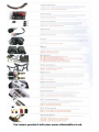
Fl.J\TBASS"" 13 SPK Bass !>peaker ciJble
~r-;.',~ ,1;',' ··~:.r··.. pL~.'.,!c'·fl:. hit',,:., -'-,p:"'r;r,!" 0'" ~..:..(l.:;-~.,. ,.....;-.!"'..;p;
tr,t.; ,~",~.- .";':; 1:;:~""\-1 ;1; (~\I.~r- ;\", i1;;~o.,;flJ ~ I. :~1.: ·:';'."':'i:, ";'. ;:r:.("_';'l~: 'J'. I f:
\';f~ wr:-:;!'; ,I.:: i'Jr:v, ~"1)("~ :.4 S:;~Ii~ nt r::;~I!(: ,,;p,::(":;~:,,,,, ·.1,!',,,:·~... u'."'!(j lu:- 8f>SS :li.'-U·I;'-~!llij'''', .. r:'.;- 'ilnt.: ;-Lf'. fjj.:.t;': ';po........" ;~... !M:
1i~~,~'7. Sr-:Jr:(::.:It......•..· ~:',lt ~.... n '-·e~Irl!Cc <:I,'1d :"'-'~l:J':! (_Il;''--';!':'·ll::;'" 'f'.'I": ;,';Wf<I' l..'-.. ;,. J.:):",-,",:r./.~:-:;~l ~.J:."1.-n·_'~r :',1:'::_.._
Model- FIat&t!>'S 1::J SPK
13 gauge 5oMJCore·... flAt. RA.~ speaker r.ab&P.
,i
\"
i
- _. _._••
'---.-----------
./,;/1
~-
(
VISE 140 amp r.trcuit bnmkEr
p,.~1 :..'l~·.l.l:n"..; -eQ'w-e rr.p !.:'-..r~;;.t:Dj~ V.HI':- i:;~';·":t.; b·',.....C'... I~; ::~~-l!(1~! ,.; ·:·:l.;~~,i'J,~ ·'··U! ;.:"p."; :ctl·.-.'!,~"s c"'-:'r~~' IJ-ClA......:·;\'1 :~,
y1ilJ, o::,yr.~e('1
:1 :!,~ :;;ystt·;p !M~" rYM~:'l;i 0: <;no~ C:r~.;b t~,.: w-'::lk,~· 'N'!: C!/.. in :;'h.' ~,!'.1; ~rJ_.l o.:-";·.'(;ni(....:~ ~~ ·i!~.~d ~~: '''''r:;~1;~
<7X!;r..·.'.. ·J(: ~.;......:-':> ~J"~.~!r~' .:-_ ~·","!l ..r.n a ~"qi!t: :.;;..-::1".:1": - i'1t.<.;O :!i"ter~; ~i::'fFi '1:-.rl ,;:st.;t';'. :-;~·.;IJ:IP :;·;':T':~Ij,,,·<n.
Mudel: ('.8140 - 140 amp circull hn;!<'lker
-
..
\
---------~
(/
\"'-------
(
,-
.~-
\
r·,..:
'"
/
.......... ----_.- ~",/
.. - -_.-----
/
FLAT Y 2M I FLAT Y 2F RCA Y I_ads
C!til' p",d;:s~·,,~)~~;':!i ct',J'-lilt-\, flfil raf1~Je DfC Y·irU;~T'(im!!Kt gVEll'ilntel% H pure 8Plj ~.ll""']:lY !.;!gnui. \,.'Vith c; flut
(Jr.!=;I!Jn ,,)l1d ti~:Tite !()di.1~f! ~cld p(!:!ted pll..l:Js ;n!e!'fen:n~e IS grr:':Jtly r~~dU(:flct T'1e HA.T-Y ir,;wrCCr'l:["!ect I!i
~~~~~l;~;~l~~f~-12~;~tl~~;;~~eTa~~~:~~i~ ;'l~:-~l: It:(llale FLi\T Y 2M cnnhgl.Jmtio~,~;.
/)
Madel: FLAT Y 2m - 1 pair RCA Y leoo 2male to 1female
----------- -----------_._------------------_._--- .--------_/
-
-
....~
~\
Slick level J"P.mote
'~~
...
r~ ';"'11 ... dO;!''':;fl i,:l !jl~!
r.:,:,d·: ('Jr:~.w
r.r;(~ 1~;Ji' f./!t"l:i~ p:'Jg ~-.f'· ~;·.:·,n:,,~ri
,
,,"V'1i- IT. :"', f)';-'i.•
~.::!~,;
tl' rlo"Tlpi!t;el"':. i~ tI,P :·;;:cr. Il~'/ci I:rmtrni ','l/hr.::h 'lllr;ws !I;!ve; adJ'..I~!,Il\€'t'1t.l.Jf i:!"if:! <rmpHfier ~(l1'l1
1;".I')t,llc 'mo tt,p :"';i'I'';O;
~.~F'I.ir.J: :11'J~.Ji
port On til(--: e''O paf)(:l uf
tr1f~ mnp!mer arid
tile
~nt:;f
\
II1
rcrnot..e galli ctJlltJ""Jl is
Model: SLR, - optional remote fur IJ~e with all Slick amplifiers
~
k1
VISE
---------------..
PonPIug'~
1hf: V18l- P.-,r-YiB9 8i~uw~; eu~;y !:::~lrID I)? rne ViO[ CBR bn!Z5 cnC!Qt;!..ln~·s_ The PcI"J~!..lgr,,~ ~ I_j~d to tight.'y
::leal till.: VlO!: T\;fb<Jhlf'!"-I if! ihe en:~!fJ~~!Jrf: t.':1 (Yother' c:re3te a ti[)'J':!!mi nf1cfos!J!"e for u~" transient
n....<:>r:n"sr:: I);' Jr. ri'"re c=-~e oj v 1'"1\.10 pmtr;!1 €:1di..i!Jll!""P. l'\l-U,:n~ U1C enclo~ure USl!~g mliy 1 Por-...P!ug r",.
Mod_I: PP25 - PortPlugN for 2.5" Tur1mPort""
Model: PPJO - PonPIug"" for 3- Tur1>oPort'·
\1
~)
~\
)
)
=============::
VlBE 086 non fused distrihLitJon block
-i~r:
Vlbr OHC, ;"1{;f', hJ~~eG d:~Lnt.I\~'..!ml l~j(J;:~~ is G pr'i.lf!..'~~,);mJ.:3.i nnn tl)"isrJ distnbution block which gives easy
\..:cnm!c~.i"}ji f:'J:- ~iP to ~ ;;1 :-1p!J!-tr'r:;; n':E~ V!6E COt:. r';l~'; ~ x 4/:1..lfJG inpllt find 4 1. 8AWG outputs which can be
w;eC fer PO'.-Y'8I' G:"Sto""i~'ut,;un w· WOI~r)d ();str;r.oi)on 'JM!"~.l ii r.Oi"':"'lrnon w'o~iriding point. tor' Dil ~stem
cGrr:r.'l1/li::r;....·;. :~!jm;rjfJ!!rl~J :!:~l ;,,;sk 01 g"Oli;~(j ~rn:J :"r.r:!I-tn·'l1nc{~
Modet: DB6 non fused distribution b1or:k
.--
I
/
/~---------------------------------------
~''''''
i
~
\
~-t
. ; , . Ff
\
..........
---
.
---
--
...'
_ -_ •
;. ,,;-
--------_._._-_._~-----------
==========::
----- ----------------------VISE RT4 / RTB crimp on ring termin~1
"~.e prC'fc~·.lon:1! m' I:]!:, of VIti£. RT l.;ulJ ;';''3tf:..,.j ;~'\~ :j·~'"T·,n ... tft ~(jr rOj;·'r:ro..:"Q rcw.,:-, c,lhlp to tnP ....r>fol('!e
r~ttel) Packt'j 'I- ~':HII~ i:!"1C ,l'Y.'.lLln", "'I\4,,"'! l)':ti 1J1~Cj,. :~.JL·l.Jr.1 0\-1-!~' lJuc{,;; w:::: (1J~ ~ii!;iY t:ti~np de~gn_
Model RT8 - 1 paw of 8 gauge cnmp on nng terminals 'Nit11 PVC overboots
Model: RT4 - 1 pair of 4 gauge cnmp on nng telTTlinals with PVC nvertmots
---------------------
~._-- -
)
/
----------------_._-------------~
All Accessories are available direct, for next day delivery call 0870 765 8423 or vist www,vibeshop_co.uk (UK ONLY)
For more produrt info seE! www.vibeiludio.l:o.uk
The CriticaIUnk"· renge of FLAT _iee cabling fram VIBE
The VISE Criticalwnk range of cabling has been deIIeIoped til achielle the critical link between $Ounce (headunlt). amplifier and speakers VISE audio equIpment is high quality. using an)U'ling less than the VI8E Cnticalwnk"" range of cables will Sellerely oompromiseyour
equipment and \Nill not allOW' it to pelfonn to its maximum potential.
MJTE: Your audto equipment will only ever be as good as the cabies you use tIl connett. it. The link bP.tween your aud~o equipment is critical
for a
~ger
_d_..
cleaner sound.
vllali _bUng ."., I n _.....
- . . eO'lb _
m:...hi
I r
f-l
c: 0 N N
f
r. 1
g
....
.,.....
.~
_ _ eaund qUB11t:y by more
All Accessories are available direct. for next day delivery call 0870 765 8423 or vist www.vibeshop.co.uk [UK ONLYj
For more produrt int=o !lee www.vibeaudio.co.uk
- - - - -.-,.-\. '- - - -..-.-. -----,J
.-. .-.r------ElASS-SYSlEM-Ki;:---------------------------,..
~,
ltl•. ~ '\"1t£ 3GL~P""'r!~, l,?t-.&<:i '-:IT:~ ::';:I/,~':if,co~i)l
.·"tl!;.:" t"";,:I' ~-": "";~.\i;. l·~.. i!.!'.~j~ .. ~,~·· ... ;);';';]1-:.
....d
,---" .--,----,-----,..\,
dc:;;W",n:~., qi'~r, ':l;:lo::,r),.;rn (!:.j~~f, 1:""""
hil"';
p',~:.r.:~ ~1_"Jo> :;'v~;I.I:')I~ h:,i~:t,r''';; ~!~ b<~~,-I~AS~~ fl"':'~:Ail"
\
!
C"::;·:llr.t.o:,'.;} ~~,!-> ,(il;.
FlAltJNF.S'" 4A'M-i PW'R PoIHer end
~d
cable
FLAT'BASS"'" 13 6Pt< &S5 ~et'" cable
~'I NCS~
18
.----....... U I:~
~"..
.. ;::
~~_
__
- _ -_-_-
nlmote
',.'--.,
~
'1','"
'.' .
.l'..i....._
~
~.\;:;:~~;~~inetedwith crimped teMTlinal rings in ,"8Ce ana' accessorv fitting kit
:::~t:~ :;'~-i~;~:;~,.t·J:I~.,
~
~ __, ~
(l:i'"!tCl"~~,'_Of ~....,,;>:r:'~L='.
\/'Ar. C"';-:
Dn tr .!':
";(j!""~'
-.. \d8E
.-ya
'~.:-or,,"rlil;<I'i.t;, ~j1;5 ..itlJ' a:;
"817'7
j
I
iiiiiii:
!'
l
k'/"t
t1!~,-~. ':,lj'i"l':'~
"iHE l'..;\S:; 11'l'I''.'l.:!!Jd: ;;;r:;pi,!'.i':'!:o
.,_tv1?_~~!BaSs,lSi:-=.~_a~~,.:'r.e"...._c_".~!'!~I~,~,~~n!l.~
--~
,.".------~----",,-----..
....-
~...
~•••
....
VIS( 140 amp CircUit breaker
\
!
I
FLATBASSn.. RCA SolidCorellollnterconnea
~
/
~/
STE'REO'SYSTEM-KIT-------------------------------------------.-.----------~"\,'
:~l~ 'li~~.·':,rjr.~ ,\I-:it:. ~:jf.!:;;d K:I
r·,r:r,c ,-,:.,!....c~.
f~(':1'
t:'"'c Ill'.?.f
!!>
~jJf!r.i;I;:::>~;1' ~.!:'·.g'1(l~
m''',gc
I.'J g,:;!I'
f\;",\'!"";'.;~'.j a!~t.p,l!: ~rJm ~';!=in
~~~~~:~.~~ ~ Power lind Ground cable
Vl'* FLAISTfRFO"" RCA - (~high defjnitJon full n;I/"1Qe interconnece::
".~l !·:i';~";'.: ~y:·;L.,·:r:~ C'.l.il,..~!r,~'~(:; 1.~lO bH~i. ~',,!;
~
~akp.r l:ablp.
~'.{.;::'
;-,.•:"j.ri..:'h:c
:!ld
if.·-:'r. ~J'il
... ·.Ilja"t'! n! ~,'n.:::.i'icr.' ~r, l"r;~, '!1,WI"'l;
Vt~F- I'C-"WI'IT,'"!;':':';
I
I
•-"yB
~;t.~-"'~
~ *,~
;i}.'-jFr\n~il~''\'
n";;!,;
i
!
....
==:--:-:-:-~~==
S~-~..
~:s:::::atedWlthCnmpedtemllnl!llnngSinpiaceandaccesSOl)'fittingkit
'.:!.:I"'~".". ;j,',)
i
= ==;:=
~=_
FtAT1..INES "'" remote 18
FlATSlFRF.O""
pr::v.·-ar
Cl"jr";'.~~jt;t'I:;·
;J",,!, ~'I. k~i ~;, V!(l!-. f,,!' i"":f.'· Gi·!:r;,~..u ..!nip'il,~~.;:.
,
!
I
,,"'w.
i
I
i LArU~'4~'-~"-' d j.',·11!l .":1No?;-
':lt~I!,,",~
,//
Model: Stereo Kit - full range stereo amplifier wiring krt
. _.. _-._--_._---_?
......, .. _,,-...__ ._-----_._------------------------------------------..
ACTIVE SYSTEM KIT
/
t'I~' \!~!-x
'I ~'J'.}"":.J.tt
r.:::owr";'J fJ,.\S.;
!..'":L" 'l.S..-,t."i ri
FLA
".
Al::~!Vl !.:5A~"'; I(;~ ,,; ::;.~~'.:,!.,~.,.:!'f aC7.lqr!r.{1 :r' !-.j~i,~ ·n.:n"'f"l~':-T'
:,~;(:{:;k~ :';'J':1jlnf1Qr,f,:' !:':1~'"i'
nil":
{;dip'Jr. frl1":
~!t, ;:I:r",~:· r"';;':\'l~ P..:,:~:; "i.~:,:.t:!I"!.•" ~t-i.:~,,:; ~~.(I~'"!.
,·,r.ti(·":VI;;'''' r;~"'~:l.·
Vl~'!i"
\
~6 "~it
n INF,S'" 8A\fIIG ~ Prwwer "nd (:jruun(l c~
HAII::IASS"'" RCA $obdCoreltollnten;onnect
FLATUr.ES"" remote' 8
AGU Fuse Holder
Fa!>'tPIug""
i !r.~~ljt. ~!f:i:t,;l'"Y
H,'.":' i"~."':; ':r::IT"r;;..iI.;')t~' W:!!l :.'~':_
""":':-'-".:,0
d ;~orJp;'ii'e:"$ '.11: l).~ i"i~rit!~t
V!F:if. 1"'e"'.;t;P1!i';·:d'; \."i.-; kt;. !!i!·
",!i \I',i!~e. ~(-;,... ~ t",)')!: "n":C'::~Jr'cf. !;~.... ,':tc:'t':~,~~ f}('C
o;,J:T',.,n;:ot.:.
Model: Active Kit - Bass specific active enclosure wiring kit
---_._---... -.....~"""·\I
1 'l~ Vlf..-lr. 1 5 ~,w:"d p(~WHr ~ ';lPtlOUJi' i'.::i a '1'.u::;l !vr "';Y ~,iOh perforri1ance 2'..ldjO ::i"~;;em. \118['5 'r .0 I,HHG u·_·ww' f:ilf.}(:l~:!!.o:·
t....:d!l!:i'S
pap btJt""i~!::n the vehicles t)r.ttef)' ':1n0 the a'Tlplifi~~"., ~rmw-i.,g r'Jp!d ::1m:")!)!.!'! r:i:tN~t.,- tl;"h\' n:S<1!tin~ in lCl..;der·
{.tlj!lU:7· ~!; .. ,:>~ ,,,mj clr.."[jn !::i!SP "mdianw~ .md tN'b!e_ lhe bu~!t Wi digit!:'!; '1c.'t.age d i.'1p:fl\" cGn:;t<ln1t'~ i·m(~ ;;;!~;:u:'{"!..Hiy di:~p!f.I'fs r.t:~
'-;Yf-ii,llfl1f-. DC \ltli~-tlge, _lJ..r; a!; '1ew VlBf power di~r;-il:;~tio,., hloek tS bu:rt ;nr.-a the rep at ~hf; (":-:jlj3:::iI:01" to oil;}'".; ear.»' wjn~,g Ir.!.n
PC'S
'1.6 farad
powe,. cepecit;or
t~le
Model PC15
_ .. _ . _ . _ _ • _ _ ...
•
',i
- - ------_.-----------------/
-
• • • k ••
\
..
•
...
...... _ _ .. _
p....v"'..
,.flf"}!";
'\11['1!;;hle ,;:'
YI."l'dl
t,p 0: fine (;Oppei' cvi".lf'lds·
jhl~-;
-----.."
!'I1f:S
\
rjf!.f,;gn m~io.t:'5 u-,~ r.;;.h:f' Ii?!. fll!;'wa"';; ut> r.:~ mtlk~ 'J<r~;Y sl!J~' h~",·.., d:Jt",
,
~." t~igtl:Y ~G'''lhl~ r~~:'19 'n~WII<ttio:1.
.r.~tp.m lnl"~".
hv
I
t..,~ ;-"i: cr
try :f1p. I'T;f:lU"ro
Model: FLATUNES 8 PWA - SQauge red power' cable Model: f-1AltJN:S B GNO - Bgauge black power cable
Model: R.ATUNES 4 PVVR - 4gau~ red power cable Model: FLATUf\ES 4 FW~ - 4gauge red power cable
_ _ _ _ _ _ _ _MOde'
"
k . _ _ . _ ..... _ _ ,~_. _ _. _
FLATUNES"'" Power and Ground C8bIe
Vit3E FiN.L;no.:$"" pr..fWl:~" csbii; "i~5 ~ij,ef1 d~·e~r.pf;'d to m~xifr:!HP.S ~n!t.<!J:I~ t,·ilr'~t(~!· I!'~l;' !JiJlb~ry in uiHni:r'"r· . T~1e C[lhi~ 'IBg ~~ Ind'r:
"',m,,!!;\] S!~C I1V ~irjl: whri.;h >.Hi': r:!ad\~
/
FLATU~.:._~_~---=-_Dge_uge_red
~'e
I
/
M_' FLATUNfS 0 GND - Ogauge blad< power cable
I,"'.~."
_/
FLATSTEREOW
High Definition
futl DF-C
range
Intsnxmnect
'.-le'"""-",,,
•.) '."·,e ,',.,'.",_'.' "",'."","',
.• "o'I'. ',"".'., ".,'.,...·c,'. ',1'
------....,\
Tj..
,~,"! Vlfif fLAT5TERED
HCA;~.=in
hj~h
ticflri!tlQ';. f'.ll' "cl1qt~ mW;,~'-l'H,['.('.r;
_
,,~..
nrnpiif.n.. · rJ1~: ~~'Hl!e mni(.'!. lJn !'flS !1'l(;r. de·.-f!IClpl~d to I-'J:l fklt W!t!~ !C", ~'I".!..J r!gl,t :;tl!)!{':' rl....r!..~'i1';J D~\"Bile! nm)-, ""!th '.mjl'Jidum ncr'Brm~n; mJt
,
I
::.h::-,riqj iltl m,t~~, H../lJ j'Jsket P.t]~J,nr! i~s<"1H;itlun~.
Y
;;~~;!~~reo RCA 1 m
----------------------~c:~~-;;~~~&;;~::;;
tL!\T8A~;~·.;'''M
i-L·~ 1.,~ i,;t;~;~!-!n l.'~~~,r,;.;
."
.,
,
.--."
,
- , rTlf!tn! full renge int2n::onnec:t
./
__________~_~~~I~~':~~~:~~._:~~~~_U_.~_~~e:_
r:!e V!f3[
,
-------. --
~~--- -~
---.
. ._.__/
~--------------------------------'"
s~~ika~lyd~~r~!Clp!'!d l;::r ;)::>l:!'P HA.::1S SySTEMS
;!"'Q,'rcnr:necthas beer.
",~ta\lctior1 . It.!i V!C-, ;ny""~dir;nt
~!; rll'f';-sj~Cjd
S;;.;:dCnm :".: CFt: mq!"'i'li W;"'1F,
:.tot:,
uJbj~~ '};\3:"e oJp has tJl;'CIJ~1 Sqpi~l·
~;!r. . . . i!"\!j;1' !1~~nv:S:'
<:10
vnl"..uge
~~ bl~" Po1~;!.>~t!
~U,'1;1 thL\ Cabi,~ lh::. i::i ~r,e ·.:enU'<:l! 'Air'€': t!.1<:1. {,,')6es V,f" ma!l; r;ip,nFl! frctl~ ~;{".:,,::e. W nmr.!ifiro;,
':'\1.I.. ~,~a:llt)
....... __
.~
__ •
::::::~=::~~~~51mm===or;::
•
Pf)wN <':Ino :,.,jqn':;l !.O r."Jc
spi'Cikcr,~
'-:D!'-:eite.- [~<-i.)Ir; :~~ rmduce:i !tr-:Jm S~lprn- i'lnf~
._~--
...._-- •• _ ...
•
,
~.
k
~'~_,
~
__ . _ /
//
--~------~-----...---- --~--~'---'---.-------------.-~,."\
FLATHEX'" High Definition -""'"' cable
~~~i~:;~:r;~ ;;~ ;:0 r<j'/o' "·'d~.i!tg
\,'
,I
,,'
T~1C i1(;+f.. r;'"'V uf
"..\
c;r; klai C!"p)ea!Uroit.:>-:
\!l Brl'( ~UdiiJ s'f':;'~m -
orc r;"pp~1'" :"''':·~ln:.i;;;. !.:'JliuetlVt<i"
!.he {".Q!"Jlc $lJper HAf"'-'
p.l:k!f":g up 811 ttl.::
VIOf.S r1,~lfl~~x QfC j'i~h dcf.r>it!Llrt
dm.ail in your mwsi::: - croe fr:~.!ti sti'i~fOds
w~li[.h (.c;f' Of' 'v,)., ~r, ...i!j:b~" Wid!;!I' c~~q.l~'"
\
}
_.~-_._--_._--_._--------~~~;~~~;;;-~.~-~-~-~~-;-;;-;;_.;;-~;;-;;;~~. --------------------_.~-~---_. ~I
...
-
YOUR RECORDS
I YEAR WARRANTY
Model
Serial Number
Date Purchased
Place of Purchase
This registration must be filled out and mailed within 10 days of purchase to validate warranty
Name
Street
ZIP Code
officE' use only
date received
State
City/Town
[]]I[O
Jelephone No:
~
dd
Email:
Product
Model: ____________~ ~ ~ ~ _Serial No
Place purchased
What other VISE equipment do you own?
Why did you purchase this VISE product? (circle one)
Sound
Oth er
Price
Dealer Recommendation
(please spec,fy)
Rate this Product {1 5
so,'e
Style
5 beIng the h'ghest)
80000
perlormance
80000
80000
sound qual<y
80000
value for money
00000
mm
yy