1
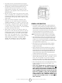
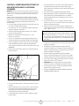
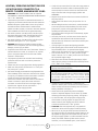
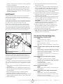
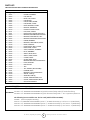
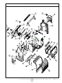
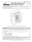
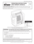
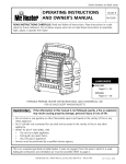
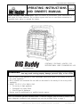
START SERIAL #MHC-748000205832
OPERATING INSTRUCTIONS
AND OWNER’S MANUAL
Model #
MH18B
READ INSTRUCTIONS CAREFULLY: Read and follow all instructions. Place instructions in a
safe place for future reference. Do not allow anyone who has not read these instructions to
assemble, light, adjust or operate the heater.
PORTABLE PROPANE HEATER FOR
RECREATIONAL AND COMMERCIAL USE
For California Sale
WARNING:
If the information in this manual is not followed exactly, a fire or explosion may result causing property damage, personal injury or loss of life.
— Do not store or use gasoline or other flammable vapors and liquids in the vicinity of this or
any other appliance.
— An LP cylinder not connected for use shall not be stored in the vicinity of this or any other
appliance.
— WHAT TO DO IF YOU SMELL GAS
• Do not try to light appliance.
• Extinguish any open flame.
• Shut off gas to appliance.
— Service must be performed by a qualified service agency.
This is an unvented gas-fired portable heater. It uses air (oxygen) from the area in which it is
used. Adequate combustion and ventilation air must be provided. Refer to page 2.
ENERCO GROUP, INC., 4560 W. 160TH ST., CLEVELAND, OHIO 44135 • 216-916-3000
04/07 78438CAL Rev. A
Mr. Heater | Big Buddy/Tough Buddy
2
Operating Instructions and Owner’s Manual
WARNING:
WARNING:
Every time hose or tank is connected to unit, connection must be checked for leaks in one or more ways:
Apply soapy water to connection, look for bubbles,
listen for hiss of escaping gas, feel for extreme cold,
smell for rotten egg odor. Do not use if leaking!
If the recreational or commercial enclosure does not
have a window or roof vent, DO NOT USE THIS HEATER
INSIDE.
THE STATE OF CALIFORNIA REQUIRES THE
FOLLOWING WARNING:
WARNING:
Any changes to this heater or its controls can be
dangerous.
WARNING:
Combustion by-products produced when using this
product contain carbon monoxide, a chemical known to
the State of California to cause cancer and birth defects
(or other reproductive harm).
WARNING:
Early signs of carbon monoxide poisoning resemble the
flu, with headache, dizziness and/or nausea. If you
have these signs, heater may not be working properly.
Get fresh air at once! Have heater serviced.
GENERAL SAFETY INSTRUCTIONS
CONTENTS
THIS IS A HEATING APPLIANCE. DO NOT OPERATE
THIS APPLIANCE WITHOUT THE FRONT WIRE
GUARD INSTALLED
• Due to high temperatures, the appliance should be
located out of traffic and away from combustible
materials.
• Children and adults should be alerted to the hazard
of high surface temperatures and should stay away
to avoid burns or clothing ignition.
• Young children should be carefully supervised when
they are near the appliance.
• Do not place clothing or other flammable material on
or near the appliance.
• Do not operate heater in any moving vehicle.
• This heater can only be used in a recreational or
commercial enclosure with a window or roof vent. It
may also be used outdoors.
• This heater requires a vent area of 18 square inches
(example 4 1/4” x 4 1/4” opening) minimum for adequate ventilation during operation. Do not use other
fuel burning appliances inside.
• GAS PRESSURE AT HEATER IS REGULATED
AND FIXED AT 11” W.C. WHEN USING A REMOTE
HOSE CONNECTION TO HEATER TANK SWIVEL(S), DO
NOT REGULATE OR REDUCE PROPANE TANK SUPPLY
PRESSURE TO HEATER.
• WARNING: ANY HOSE CONNECTION TO A
QUICK DISCONNECT FITTING ON HEATER
MUST BE REGULATED TO 11” W.C. PRESSURE
• REGULATOR IN HEATER MUST ALWAYS BE IN PLACE
DURING OPERATION.
General Safety Instructions ............................................... 3
General Information ......................................................... 4
Operating with Disposable Propane Cylinders ................... 5
Operating With Hose Connected to Remote Cylinder ........ 6
Maintenance .................................................................... 7
Troubleshooting ............................................................... 7
Parts List .......................................................................... 8
Parts Ordering Information ............................................. 10
Service Information ........................................................ 10
SPECIFICATIONS
MODEL NO. ................................................ MH18B
GAS TYPE ............................................. P R O P A N E
INPUT BTU/HR. .................... 4,000 / 9,000 /18,000
CLEARANCE TO COMBUSTIBLES
T O P .................................................................... 30”
F R O N T ............................................................... 24”
S I D E S .................................................................... 6”
R E A R ..................................................................... 0”
Caution: Some carpets or linoleum surfaces may discolor if
heater is placed directly on these floor coverings.
Mr. Heater | Big Buddy/Tough Buddy
3
Operating Instructions and Owner’s Manual
04/07
78438CAL Rev. A
• Any safety screen or guard removed for servicing the
•
•
•
•
•
appliance must be replaced prior to operating the heater.
The appliance should be inspected before each use.
Frequent cleaning may be required. The control
compartments, burner(s) and circulating air passageways of the appliance must be kept clean, see
MAINTENANCE.
DO NOT use this heater if any part has been under
water. Immediately call a qualified service technician
to inspect the heater and to replace any part of the
control system and any gas control, which has been
under water.
When used without adequate combustion and
ventilation air, this heater may give off excessive
CARBON MONOXIDE, an odorless, poisonous gas.
Some people - pregnant women, persons with heart
or lung disease, anemia, those under the influence
of alcohol, those at high altitudes - are more affected
by carbon monoxide than others.
When heater is placed on the ground, make sure
the ground is level and keep any objects at least 24
inches from the front of the heater. THIS HEATER
IS EQUIPPED WITH A TIP OVER SWITCH THAT
WILL SHUT THE HEATER OFF IF THE HEATER
TIPS OVER HOWEVER, DO NOT LEAVE HEATER
UNATTENDED OR WHERE CHILDREN MAY
CAUSE THE HEATER TO TIP OVER. NEVER
OPERATE THE HEATER WHILE SLEEPING!
GENERAL INFORMATION:
• This heater is safe for indoor use in small recreational
enclosures, having means for providing combustion air
and ventilation, such as enclosed porches, cabins, fishing
huts, trailers, tent trailers, tents, truck caps and vans. It
may be used in commercial enclosures, having means for
providing combustion air and ventilation, such as
construction trailers or temporary work enclosures.
Note: The heater can be used outdoors, but may experience nuisance shutoffs in certain wind conditions.
• When the heater is cold or at room temperature, it will
take a few minutes for the burner(s) tile to turn bright
orange. This is normal and the heater is working properly. If burner(s) tile is visibly flaming, turn heater off and
call a qualified service technician.
• When the unit is lit, there should be about a quarter
inch border around the tile that will not turn bright
orange. This is normal.
• When operating the heater at altitudes over 7,000 FT.
above sea level, the unit may not burn as bright as in
lower altitudes. This is normal. At higher altitudes, the
heater may shut-off. If this happens, provide fresh air,
wait 5 minutes and re-light. Due to local atmospheric
conditions heater may not re-light.
• Operating time will vary depending on the heater setting
and the supply cylinder size. (One 1 lb. cylinder: 1.5 to 6
hours. Two 1 lb. cylinders: 3 to 12 hours. Two 20 lb.
cylinders: 50 to 220 hours.) Heater may be operated
from quick disconnect, one or both tank swivel inlets.
• When moving heater when lit or bumping heater setting
it down, tip over switch may shut off heater. If this
happens, re-light.
• NOTE: THIS HEATER MAY BE OPERATED WITH (1)
OR (2) DISPOSABLE 1 LB. PROPANE CYLINDERS OR
WITH A REMOTE REFILLABLE CYLINDER(S) MAX. 20
LBS USING (1) OR (2) F273701, F273702 OR F272702
HOSE ASSEMBLIES WITH FUEL FILTERS (F273699) ON
EACH HOSE ASSEMBLY. IT MAY ALSO BE OPERATED
WITH (1) F271802 HOSE ASSEMBLY CONNECTED TO
A REGULATED (11” W.C.) PROPANE SOURCE OR (1)
F271803 HOSE ASSEMBLY WITH 11” REGULATOR
WITH ACME NUT.
Mr. Heater | Big Buddy/Tough Buddy
4
Operating Instructions and Owner’s Manual
LIGHTING / OPERATING INSTRUCTIONS FOR
USE WITH DISPOSABLE 1 LB. PROPANE
CYLINDERS:
• Once the pilot has lit, hold the Control Knob down for
WARNING: Always inspect propane cylinder and heater propane
connections for damage, dirt, and debris before attaching propane
cylinder. Do not use if head of cylinder is damaged, punctured or
deteriorated.
ALWAYS ATTACH OR DETACH CYLINDER OUTDOORS AWAY
FROM FLAMES, OTHER IGNITION SOURCES, AND ONLY WHEN
HEATER IS COOL TO TOUCH. NEVER SMOKE WHEN ATTACHING
OR REMOVING PROPANE CYLINDER OR MAKING REMOTE
CONNECTIONS!
•
•
•
• Use only LP-gas cylinders marked in accordance with the
•
•
•
•
•
•
•
U.S. Dept. of Transportation (DOT).
Use only 16.4 oz. (1 lb.) disposable cylinders that mate
with No. 600 valve connection.
Heater and attached cylinder(s) must be in an upright
position during operation.
Make sure five-position Control Knob is in “OFF”
position; see Figure 1.
Screw 1 lb. disposable LP-gas supply cylinder(s) clockwise (from bottom) into portable heater until hand-tight.
Check cylinder(s) connection for leaks with soapy water
at the threaded connection under the domed plastic
cover where the cylinder screws into the tank swivel. SEE
WARNING!
Depress the Control Knob and turn counterclockwise to
the pilot postion.
an additional 30 seconds to heat the thermocouple.
After 30 seconds, release the Control Knob and the pilot
should remain lit.
If the pilot goes out repeat the lighting procedure.
After lighting pilot, release Control Knob. Control Knob
should return to fully extended position. To operate
heater slightly depress knob and gently turn to lock in
desired position.
Turn control knob to “LO” or “MD” position to light
heater. Leave on “LO” or “MD” position until first burner
tile has turned bright orange.
After first burner tile has turned bright orange, adjust
heat output by turning Control Knob to desired position
(“LO”, “MD” or “HI”)
Warning:
DO NOT OPERATE HEATER UNLESS CONTROL KNOB IS LOCKED
IN A POSITION MARKED “HI”, “MD”, “LO” or “PILOT”. NEVER
SET CONTROL KNOB BETWEEN LOCKED POSITIONS. POOR
COMBUSTION AND HIGHER LEVELS OF CARBON MONOXIDE
MAY RESULT.
• For added heat circulation turn red fan switch to on. The
•
•
Fan Switch
•
•
•
•
fan switch is located just left of control knob side handel
support. See Figure 1.
Installation of 4 D-cell batteries is required for fan
operation. Battery box is located on lower back panel of
heater. Follow instructions on battery cover for correct
battery installation. See figure 2.
Heater can also be powered by electrical adapter
F276127. Required adapter to be 6 volt DC up to 800
milliamp current with positive tip polarity. See figure 2.
To shut off heater, slightly push down and turn Control
Knob clockwise to “OFF” position.
CAUTION: After turning heater off, wire guard will
remain hot. Allow to thoroughly cool before storing.
Do not operate, store or remove cylinder(s) near flammable items or ignition sources.
LP-GAS CYLINDERS MUST BE DISCONNECTED FROM
HEATER WHEN NOT IN USE!
Control Knob
Figure1
• Hold Control Knob down in the pilot position for 30-40
seconds.
• While holding down the Control Knob, rotate clockwise
•
to the OFF position and immediately turn back to the
pilot position, a spark will be generated at the pilot
assembly and the heater should light.
If the heater does not light on the first attempt, repeat
the procedure.
Mr. Heater | Big Buddy/Tough Buddy
5
Operating Instructions and Owner’s Manual
04/07
78438CAL Rev. A
LIGHTING / OPERATING INSTRUCTIONS FOR
USE WITH HOSE(S) CONNECTED TO A
REMOTE CYLINDER, MAXIMUM SIZE 20 LBS:
• Check all hose connections for leaks with soapy water at
• WARNING: ANY HOSE CONNECTION TO A QUICK
DISCONNECT FITTING ON HEATER MUST BE REGULATED
TO 11” W.C. PRESSURE
• This Heater may be used in a Recreational Enclosure or
Temporary Construction Work Enclosure with a Remote
Refillable Propane Cylinder ONLY when the Cylinder is
Located Outdoors and the Heater is Used with Mr.
Heater Hose No. F273701, F273702 or F272702 and fuel
filter F273699. Fuel filter must be replaced annually.
• Mr. Heater Hose No. F271802 which includes a quick
disconnect fitting and a 3/8” female flare fitting connected to a regulated (11” W.C.) propane source.
• Mr. Heater Hose No. F271803 which includes a quick
disconnect fitting and a 11” W.C. regulator.
• DANGER: NEVER bring a refillable propane cylinder
indoors. A fire or explosion can occur causing property
damage, serious injury or death!
• Inspect the hose before each use of the heater. If there is
excessive abrasion or wear, or the hose is cut, replace
prior to using the heater with one of the Mr. Heater
Hose No’s. shown above.
• The propane cylinder must include a listed overfilling
protection device as well as a collar to protect the
cylinder valve.
• Heater must be in an upright position during operation.
• Make sure five-position control knob is in “OFF” position; see Figure 1, at left.
• Mr. Heater strongly recommends using disposable fuel
filter F273699, which connects to tank swivel on heater
to trap any oil substances when connected to a remote
cylinder that can make the heater inoperable.
• Screw hose connector into tank swivel or fuel filter on
heater or connect to quick disconnect and screw
connector on other end of hose into LP-gas supply
cylinder valve. Tighten all hose connections.
• Open valve at LP-gas supply cylinder.
•
•
•
•
•
•
•
•
•
Warning:
DO NOT OPERATE HEATER UNLESS CONTROL KNOB IS LOCKED
IN A POSITION MARKED “HI”, “MD”, “LO”or “PILOT”. NEVER
SET CONTROL KNOB BETWEEN LOCKED POSITIONS. POOR
COMBUSTION AND HIGHER LEVELS OF CARBON MONOXIDE
MAY RESULT.
• Installation of 4 D-cell batteries is required for fan
•
Electrical Adapter Outlet
•
•
•
Electrical adapter
Figure 2
Mr. Heater | Big Buddy/Tough Buddy
the threaded connection under the domed plastic cover
where the hose connector screws into the tank swivel
and/or fuel filter and at LP-gas supply cylinder. SEE
WARNING!
Depress the control knob and turn counter-clockwise to
the pilot position.
Hold control knob down in the pilot position for 1-5
minutes.
While holding down the control knob, rotate clockwise
to the OFF position and immediately turn back to the
pilot position, a spark will be generated at the pilot
assembly and the heater should light.
If the heatere does not light on the first attempt, repeat
the procedure.
Once the pilot has lit, hold the control knob down for
an additional 30 seconds to heat the thermocouple.
After 30 seconds, release the control knob and the pilot
should remain lit.
If the pilot goes out repeat the lighting procedure.
After lighting pilot, release knob. Knob should return to
fully extended position. To operate heater slightly
depress knob and gently turn to lock in desired position.
Turn control knob to “LO” or “MD” position to light
heater. Leave on “LO” or “MD” position until first burner
tile has turned bright orange.
After first burner tile has turned bright orange, adjust
heat output by turning Control Knob to desired position
(“LO”, “MD” or “HI” setting).
Caution: Do not try to adjust heating levels by using
the propane tank shut-off valve,
6
operation. Battery box is located on lower back panel of
heater. Follow instructions on battery cover for correct
battery installation. See figure 2.
Heater can also be powered by electrical adapter,
F276127. Required adapter to be 6 volt DC up to 800
milliamp current with positive tip polarity. See figure 2.
To shut off heater, shut off propane at supply tank,
allow heater to use-up propane in supply line until
heater shuts off, then slightly push down and turn
Control Knob clockwise to “OFF” position.
CAUTION: After turning heater off, wire guard will
remain hot. Allow to thoroughly cool before storing.
When not in use, the gas must be turned off at the LPgas supply cylinder. As stated before allow heater to use
up propane in supply line until heater shuts off. When
the LP-gas supply cylinder is not disconnected from the
heater, the heater and the cylinder must be stored
outdoors, in a well ventilated space, out of reach of
Operating Instructions and Owner’s Manual
•
children, and must not be stored in a building, garage or
any other enclosed area.
Indoor storage of the heater is permissible only if the
cylinder is disconnected and removed from the heater.
Cylinders must be stored outdoors out of the reach of
children and must not be stored in a building, garage or
any other enclosed area.
6 Remove (3) screws attaching lower baffle to expose
burner air openings.
7 Inspect interior of casing assembly for accumulation of
dust, lint or spider webs. If necessary, clean interior of
casing assembly with a vacuum cleaner or apply air
pressure (max. 30 psi). Do not damage any components
within casing assembly when you are cleaning.
8 Inspect and clean main burner orifice located at bottom
of burner venturi tube, by using a vacuum or apply air
pressure at orifice opening.
9 Inspect and clean pilot (mounted to bracket) by using a
vacuum or apply air pressure through the holes in the
pilot indicated by the arrows in Figure 3.
WARNING: Never use needles, wires, or similar cylindrical objects to clean the pilot to avoid damaging the
calibrated ruby that controls the gas flow.
10 Apply air pressure (max. 30 psi) into ceramic tile of
burner(s) assembly and the venturi tube (with [2] air
openings) to remove dust, lint or spider webs.
11 Reinstall lower baffle with (3) screws
12 Slide back cover over (2) plastic hooks on top of heater.
Make sure rear cover aligns with plastic side covers.
Install (4) screws to hold in place.
MAINTENANCE:
Always keep the heater area clear and free from combustible
materials, gasoline and other flammable vapors and liquids.
Keep the vent areas (slots in the bottom and the top at the front
of heater) clear at all times.
Visually inspect the pilot flame and burner periodically during use.
The pilot flame should be blue in color (not yellow) and will extend
beyond the thermocouple. The flame will surround the
thermocouple just below the tip, see Figure 3. A slight yellow
flame may occur where the pilot flame and main burner flame
meet. The burner(s) should be bright orange (with a slight blue
color around the border, a red-orange haze that is visible on the
ceramic tile is acceptable) and without a noticeable flame. A blue
flame that rolls out at the top of the ceramic tile indicates an
TROUBLESHOOTING INFORMATION:
If Spark electrode does not produce spark.
CHECK
• Spark electrode broken – replace.
• Igniter wire may not be attached to spark electrode –
attach.
• Igniter wire damaged – replace.
• Piezo igniter on control valve defective – replace control
valve.
If Spark electrode produces spark but pilot does not light.
CHECK
• No gas to heater – install disposable cylinder or connect
hose and fuel filter then turn on valve at remote cylinder.
• “PILOT” position not properly aligned – turn gas control
knob to “PILOT” position and depress.
• Pilot is blocked from spider web or dirt – clean pilot, see
MAINTENANCE.
If Pilot flame does not stay lit when knob is released.
CHECK
• Control knob in “PILOT” position not completely
depressed or held in long enough to purge air from lines.
• Pilot flame not surrounding thermocouple – clean pilot,
see MAINTENANCE.
• Pilot Assembly defective – replace.
•
Tip switch wires disconnected – connect.
If Main burner(s) does not ignite.
CHECK
• Main burner(s) orifice is blocked – clean burner(s), see
MAINTENANCE.
If Heater keeps shutting “OFF” during normal operation.
CHECK
• Pilot is blocked – clean pilot, see MAINTENANCE.
• Provide minimum fresh air opening of 18 square inches
(example 4 1/4” x 4 1/4” opening).
• Tip over switch activated from bumping heater. Re-light
Figure 3
accumulation of dust, lint or spider webs inside the casing
assembly and main burner assembly. If the pilot is yellow or the
burner has a noticeable flame, cleaning may be required. Use the
following procedure to inspect the casing assembly and main
burner assembly.
It is necessary to periodically check the burner(s) orifice and burner
venturi tube to make sure they are clear of insects/nests or spider
webs that may accumulate over time. A clogged tube can lead to
a fire.
1 Allow heater to thoroughly cool before performing any
maintenance.
2 Remove disposable 1 lb. cylinder(s) from heater or turn
OFF gas supply at remote cylinder valve, and disconnect
hose from heater.
3 Remove wire guard from front of heater by gently
bending to remove from holes in front cover.
4 Remove (4) screws securing back cover to heater. Lift up
slightly to release (2) plastic hooks on top of back cover.
5 Remove back cover.
Mr. Heater | Big Buddy/Tough Buddy
7
Operating Instructions and Owner’s Manual
04/07
78438CAL Rev. A
PARTS LIST:
SEE BACK PAGE FOR PARTS ORDERING INFORMATION
REF. #
ITEM #
DESCRIPTION
Big Buddy
1 ... 78402 .............................. HANDEL, ASSEMBLY
2 ... 78403 .............................. FAN, SWITCH
3 ... 78404 .............................. BACK, FAN, COVER
4 ... 78405 .............................. FAN, MOTOR
5 ... 78406 .............................. FAN, BLOWER, WHEEL
6 ... 78407 .............................. FAN, INTAKE, COVER
7 ... 78408 .............................. DOOR, BATTERY, COVER
8 ... 78409 .............................. BATTERY, TERMINALS
9 ... 78410 .............................. DOOR LEFT SIDE COVER
10 . 78411 .............................. LEFT, SIDE, COVER
11 . 78451 .............................. REGULATOR, MH18B, SIDE INLET
12 . 78453 .............................. BRACKET, RETAINING, REGULATOR
13 . 78454 .............................. BRACKET, TANK SWIVEL, LEFT
14 . 78452 .............................. BRACKET, MOUNTING, REGULATOR
15 . 78416 .............................. FRAME, ASSEMBLY
16 . 78455 .............................. BRACKET, TANK SWIVEL, RIGHT
17 . 78418 .............................. KNOB, CONTROL
18 . 78419 .............................. DOOR, RIGHT, SIDE, COVER
19 . 78420 .............................. RIGHT, SIDE, COVER
20 . 78421 .............................. VALVE, CONTROL, ASSEMBLY
21 . 78422 .............................. PILOT, ASSEMBLY
22 . 78423 .............................. SHIELD, HEAT, BACK
23 . 78424 .............................. SHIELD, HEAT, FRONT
24 . 78425 .............................. COVER, FRONT
25 . 78426 .............................. GUARD, WIRE, FACE
26 78427
BRACKET, BOTTOM, PLENUM ASS’Y
27 . 78428 .............................. PILOT, BRACKET
28 . 78429 .............................. REFLECTOR
29 . 73439 .............................. TILE
30 . 73433 .............................. TILE, GASKET (NOT SHOWN)
31 . 78431 .............................. PLENUM, BODY
32 78432
BRACKET, TOP, PLENUM ASS’Y
33 . 78439 .............................. SWIVEL, TANK (2)
34 . 78440 .............................. ADAPTER, TANK (2)
35 . 78462 .............................. COVER, TANK ADAPTER, LEFT
36 . 78463 .............................. COVER, TANK ADAPTER, RIGHT
37 . 78460 .............................. QUICK DISCONNECT
ACCESSORIES
ITEM#
RECOMMEDED
DESCRIPTION
F271802 - 12 ft. PROPANE HOSE ASSEMBLY w/quick disconnect fittings and 3/8” female flare fitting
F271803 - 12 ft. PROPANE HOSE ASSEMBLY w/quick disconnect fittings and 11” W.C. regulator w/Acme nut.
The following hose assemblies can also be used (with fuel filter F273699).
F273699 Fuel Filter (Replace Annually)
F273701 - 5 ft. PROPANE HOSE ASSEMBLY (Swivel 1”- 20 Male Throwaway Cyl. Thd. X P.O.L. w/Handwheel)
F273702 - 12 ft. PROPANE HOSE ASSEMBLY (Swivel 1”- 20 Male Throwaway Cyl. Thd. X P.O.L. w/Handwheel)
F272702 - 12 ft. PROPANE HOSE ASSEMBLY (Swivel 1”- 20 Male Throwaway Cyl. Thd. X P.O.L. w/Handwheel)
Mr. Heater | Big Buddy/Tough Buddy
8
Operating Instructions and Owner’s Manual
Mr. Heater • Big Buddy • Tough Buddy • Model # MH18B
1
17
18
2
3
19
7
36
5
12
4
16
11
8
20
32
6
13
14
15
31
29
28
34
35
10
21
33
37
9
26
27
22
23
24
25
Mr. Heater | Big Buddy/Tough Buddy
9
Operating Instructions and Owner’s Manual
04/07
78438CAL Rev. A
OPERATING INSTRUCTIONS
AND OWNER’S MANUAL
Model #
MH18B
WARNING:
USE ONLY MANUFACTURER’S REPLACEMENT PARTS. USE OF ANY OTHER PARTS COULD
CAUSE INJURY OR DEATH. REPLACEMENT PARTS ARE ONLY AVAILABLE DIRECT FROM
THE FACTORY AND MUST BE INSTALLED BY A QUALIFIED SERVICE AGENCY. MR. HEATER
HOSES F273701 F273702 AND F272702 ARE SPECIFICALLY DESIGNED FOR USE WITH
THIS HEATER ALONG WITH F273699 DISPOSABLE FUEL FILTER. (REPLACE ANNUALLY).
USE OF OTHER HOSES MAY CAUSE THE HEATER TO BECOME INOPERABLE.
PARTS ORDERING INFORMATION:
PURCHASING: Accessories may be purchased at any Mr. Heater local dealer or
direct from the factory
FOR INFORMATION REGARDING SERVICE
Please call Toll-Free 800-251-0001
www.mrheater.com
Our office hours are 8:30 AM – 5:00 PM, EST, Monday through Friday.
Please include the model number, date of purchase, and description of problem
in all communication.
LIMITED WARRANTY
Enerco Group, Inc. warrants its heaters and accessories to be free from defects
in material and workmanship for a period of 1 year from date of purchase.
Enerco Group, Inc. will repair or replace this product free of charge if it has been
proven to be defective within the 1-year period, and is returned at customer
expense with proof of purchase to Enerco Group, Inc. within the warranty period.
Enerco Group, Inc. reserves the right to make changes at any time, without notice or
obligation, in colors, specifications, accessories, materials and models.
ENERCO GROUP, INC., 4560 W. 160TH ST., CLEVELAND, OHIO 44135 • 216-916-3000
Mr. Heater and Big Buddy are registered trademarks of Enerco Group, Inc.
© 2003, Enerco/Mr. Heater. All rights reserved
CSA 4.98
U.S.
Mr. Heater | Big Buddy/Tough Buddy
10
Operating Instructions and Owner’s Manual