1
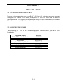
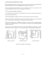
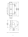
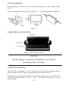
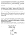
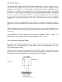
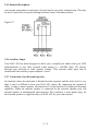
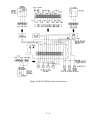
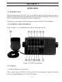
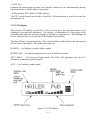
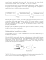
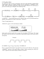
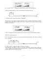
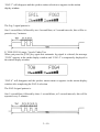
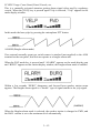
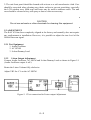
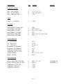
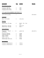
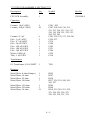
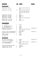
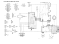
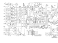
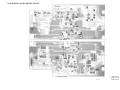
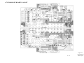
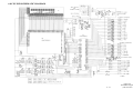
RAY430
LOUDHAILER
INSTALLATION & OPERATION INSTRUCTIONS
PURPOSE
THIS MANUAL CONTAINS IMPORTANT INFORMATION ON THE INSTALLATION,
OPERATION AND MAINTENANCE OF YOUR EQUIPMENT
Raymarine products are supported by a network of Authorized Service Representatives. For product
information, you may contact the following regional centers:
The Americas:
Raymarine, Inc.
22 Cotton Road,
Unit H, Nashua
NH 03063-4219, USA
+1 603 881 5200
+1 800 539 5539
Fax +1 603 864 4756
For Technical Support:
+1 800 539 5539 ext. 2444
+1 603 881 5200 ext. 2444
+44 (0) 23 92 714713
UK, Europe, Rest of the World:
Raymarine Ltd.
Anchorage Park
Portsmouth
Hampshire, UK
PO3 5TD
+44 23 92 693611
Fax +44 23 92 694642
Worldwide / USA - Toll-free within the
USA
Worldwide / USA
Worldwide / UK
IMPORTANT NOTICE
THIS DEVICE IS ONLY AN AID TO BOATING SAFETY AND NAVIGATION. ITS
PERFORMANCE CAN BE AFFECTED BY MANY FACTORS INCLUDING EQUIPMENT
FAILURE OR DEFECT, ENVIRONMENTAL CONDITIONS, AND IMPROPER HANDLING
OR USE. IT IS THE USER’S RESPONSIBILITY TO EXERCISE COMMON PRUDENCE
AND NAVIGATIONAL JUDGMENT. THIS DEVICE SHOULD NOT BE RELIED ON AS A
SUBSTITUTE FOR SUCH PRUDENCE AND JUDGMENT.
TABLE OF CONTENTS
SECTION 1 GENERAL
1.1
1.2
1.3
INTRODUCTION
EQUIPMENT FEATURES
SPECIFICATIONS
1-1
1-1
1-2
SECTION 2 INSTALLATION
2.1
2.2
2.2.1
2.3
2.4
2.4.1
2.5
2.5.1
2.5.2
2.5.3
2.5.4
2.5.5
2.5.6
2.5.7
UNPACKING AND INSPECTION
EQUIPMENT SUPPLIED
Optional Accessories
STORAGE
PLANNING THE INSTALLATION
Mounting Options
ELECTRICAL CONNECTION
DC Power Connections
Intercom Speaker(s)
Hailer Horn(s)
Connection of Burglar Alarm
Remote Microphone
Auxiliary lnput
Connection of an External Speaker
2-1
2-1
2-2
2-2
2-3
2-5
2-5
2-5
2-6
2-7
2-7
2-7
2-8
2-8
SECTION 3 OPERATION
3.1
3.2
3.2.1
3.2.2
3.3
3.3.1
3.3.2
3.3.3
3.3.4
INTRODUCTION
CONTROLS AND LCD DISPLAY
Controls
LCD Display
OPERATING PROCEDURES
The Power Switch/Dimmer Control
Volume Control (Hail & Listen)
Hail Mode
Intercom Operation
i
3-1
3-1
3-1
3-3
3-5
3-5
3-5
3-6
3-6
3.3.5
3.3.6
Fog Horn Mode.
Aux Mode.
3-8
3-13
SECTION 4 TECHNICAL DESCRIPTION
4.1
BLOCK DIAGRAM
4-1
SECTION 5 MAINTENANCE
5.1
5.1.1
5.2
5.3
5.3.1
5.3.2
5.3.3
5.3.4
GENERAL
Product and Customer Service
PREVENTATIVE MAINTENANCE
ADJUSTMENT
Test Equipment
Listen Output Adjustment
Intercom Output Adjustment
Level Meter Adjustment
5-1
5-1
5-1
5-2
5-2
5-2
5-3
5-3
SECTION 6 PARTS LIST & DRAWINGS
6.1
6.2
6.3
6.4
6.5
6.6
6.7
6.8
6.9
PARTS LIST
ASSEMBLY DRAWING
PARTS LIST FOR ASSEMBLY DRAWING
INTERNAL WIRING DIAGRAM
MAIN SCHEMATIC DIAGRAM
LINEAR A PCB PARTS LAYOUT
LINEAR B PCB PARTS LAYOUT
CPU PCB SCHEMATIC DIAGRAM
CPU PCB PARTS LAYOUT
ii
6-7
6-8
6-9
6-11
6-12
6-13
6-14
6-15
6-16
SECTION 1
GENERAL DESCRIPTION
1.1 INTRODUCTION
Congratulations on your purchase of the RAY 430 Multifunction Loudhailer.
The RAY 430 Loudhailer is a multipurpose device that may be used as a ship-to-shore
hailer, ship-to-ship hailer, foghorn, audio amplifier, intercom, and/or alarm system.
As a loudhailer, the RAY 430 amplifies your voice up to a 30 watt level, for hailing
through the hailing horn speaker, and when listening for replies, amplifies the incoming
sounds to the desired listening level. If an additional (optional) horn is added to the
system, the loudhailer output can be switched to either or both of the hailing horn
positions by the front panel control.
To verify your ownership and warranty registration, you should take a few minutes and
fill out your warranty registration card found just inside the front cover of this manual.
It is very important that you take the time to fill this card out. The warranty registration
card should be returned to the factory immediately after your purchase in order to
receive full warranty benefits.
Section 5 in this manual provides further information on obtaining Customer Service
and Product Support which is available to you as a valued customer.
1.2 EQUIPMENT FEATURES
The RAY 430 is designed and manufactured to provide ease of installation and
operation with excellent reliability. Some of the important built-in features of the
equipment are listed below.
The loudhailer horns(s) are used as sound dispersal points when the RAY 430 is used as
a foghorn so that the full 30 watt output of the unit can be employed.
In the foghorn mode any of six programmed foghorn patterns can be automatically
generated. They are: Underway, Stopped, Sail, Tow, Anchored, and Aground.
INTERCOM — Provides 2-way communication between the display unit and up to 4
connected remote units, which can also originate a call to the display unit.
AUXILIARY MODE — Allows the selective or simultaneous transmission of an
external audio input to all stations. For entertainment, the external audio can be a
cassette deck, radio, or CD player. For business, it can also be any other instrument
having an external audio output, such as the output from a VHF or SSB radiotelephone.
1—1
EXTERNAL ALARM CONNECTION — For external systems or security alarm
sensors.
EASY TO USE — An ideal arrangement, the RAY 430 has an illuminated keyboard
and LCD which clearly shows all selected stations and operating modes.
DURABLE, WATERPROOF CONSTRUCTION — With rugged gaskets and our
heavy-duty microphone the RAY 430 is built to survive in the toughest marine
environments.
SILICONE RUBBER KEYBOARD — Has backlighting for easy night-time viewing
and operation.
OPTIONAL FLUSH-MOUNT KIT — For attractive customized mounting into
overhead instrument cabinets or in the console of your bridge.
1.3 SPECIFICATIONS
Dimensions:
4 3/4 x 9 3/16 x 4 1/2 inches (121 x 234 x 114 mm)
Height x Width x Depth
Weight
Approximately 1.9 Kg (4.3 lbs)
Power supply
13.6 VDC nominal (±20%) 5 amps or less
Audio Output
Hail Speaker 30W
Intercom Speaker 4.5W
Ext. Speaker 4.5W
Int. Speaker 2.5W
Output impedances
Hail Speaker 8 ohms
Intercom Speaker 8 ohms
Ext. Speaker 8 ohms
Input Impedance
Mic. Impedance 600 ohms Aux Impedance 10K ohms
Input Sensitivity
Mic. Sensitivity -40 dB 3dB (at 1KHz)
Aux Sensitivity -10 dB 3dB (at 1KHz)
SP/Mic Sensitivity 6mV RMS ±20%
Frequency Response Hail Mode 100Hz to 8KHz 5dB
Listen Mode 100Hz to 8KHz 5dB
Aux Mode 100Hz to 20KHz 5dB
Distortion Factor
Hail Mode 10% or less (at 1KHz 30W)
Listen Mode 10% or less (at 1KHz SW)
Aux Mode 10% or less (at 1KHz 30W)
Signal to Noise Ratio Hail Mode 60dB or more (at 1KHz)
Listen Mode 60dB or more (at 1KHz)
Aux Mode 60dB or more (at 1KHz)
Horn Frequency
500Hz ± 50Hz
1—2
SECTION 2
INSTALLATION
2.1 UNPACKING AND INSPECTION
Use care when unpacking your new RAY 430 from the shipping carton to prevent
damage to the contents. It is also a good practice to save the carton and the interior
packing material. The original packing material should be used in the unlikely event that
it becomes necessary in the future to return the unit for service.
2.2 EQUIPMENT SUPPLIED
The following is a list of the standard equipment included with your RAY 430
Loudhailer.
Equipment Name
RAY 430 Loudhailer Unit
Hailer Horn
Microphone
Microphone Mounting Bracket
Mounting Yoke
Bridge Card
Instruction Manual
Part No.
M95997
M95435
0263596-2
0263596-3
0263596-4
G263647-4
G263647-5
2—1
2.2.1 Optional Accessories
Item #
1
2
3
4
5
6
Description
Console Mounting Kit (Flush Mount)
Console Mounting Kit (Trim Ring Style)
Power Supply, 115/220 VAC to 1 2 VDC
Sun Cover
Intercom Speaker
Hailer Horn
Part No.
M95990
M95995
M59733
G263696- 1
M95998
M95435
2.3 STORAGE
After all of the components have been unpacked and inspected, they should be replaced
in their shipping containers and stored in a dry place until they are to be installed. The
storage area should be dry, well-ventilated and not subjected to temperature extremes
below -20°C or above +55 °C.
2—2
2.4 PLANNING THE INSTALLATION
When planning the location for your RAY 430 to be installed, the following conditions
should be considered to insure dependable and trouble-free operation.
1) The mounting location should be easily accessible to allow easy operation of the
front panel and provide the best viewing angle of the display.
2) There should be adequate ventilation.
3) A sufficient space should be secured behind the unit to allow all cable connections to
the rear panel terminal strip.
4) The mounting place should be located as near to the power source as possible.
5) The selected location should be isolated away from devices that may cause offending
noise or interference, such as motors, steering cables and generators.
6) Generally speaking, the Loudhailer should be protected from prolonged direct
exposure to rain and salt spray. It is a good practice to protect this valuable equipment
as much as possible.
The unit can be conveniently mounted on a chart table, bulkhead, overhead or any other
desired place. (Refer to Figure 2- 1 for typical locations and mounting configurations)
(table top mount)
(bulkhead mount)
Figure 2-1 Examples of installation
2—3
(overhead mount)
Figure 2-2 Outline and Mounting Dimensions
2—4
2.4.1 Mounting Options
Flush-mounting your RAY430 can be performed using one of the methods shown
below.
Console Mounting Kit (Trim Ring Style-M95995)
Console Mounting Kit (M95990)
Figure 2-3
2.5 ELECTRICAL CONNECTION
Figure 2-4 RAY430 Rear Panel
CAUTION
DO NOT INSTALL THIS RADIO ON VESSELS WITH POSITIVE
GROUND BATTERY SYSTEMS.
2.5.1 DC Power Connections
The RAY 430 is intended for use on vessels with 12 VDC power systems and can
operate as long as the DC supply is regulated between 10.8 and 16 VDC.
The input power connections are made at the terminal strip on the rear of the RAY 430
unit at the terminals labeled “ 13.6V” “+“ and “–“. See Figure 2-8 on page 2-9 for the
exact locations.
2—5
The power leads should normally be routed to the ship’s DC power distribution panel
on larger boats. The RAY430 is fused at 10 amps so connection to a 10 amp or
(maximum of) 15 amp circuit breaker is recommended. On smaller vessels the power
leads may be connected directly to the main battery, isolation switch, or circuit breaker.
For best noise isolation from other shipboard electronics avoid grouping the loudhailer
power connections with radar, radio, or echo sounder power leads together on the same
circuit breaker.
Although the RAY 430’s power consumption is only 65 watts (maximum), if you find
that the power cable leads need to be extended more than 10 feet, the wire size of the
leads should be in-creased accordingly to minimize line losses. For runs of 20-35 feet
#12 AWG is recommended, remember to always solder all connections on all your
power cord additions.
Observe proper polarity! The wire connected to the positive (+) terminal must be
connected to the positive point of the DC power source; The wire connected to the
Negative (—) terminal of the terminal strip must be connected to the negative point of
the DC power source. If the power leads are accidentally reversed, the 10 Amp fuse will
blow. If this happens, recheck the polarity of the connections with a voltmeter (VOM)
and, if necessary, reverse the leads for proper connection. Then replace the 10 amp fuse
in the power cord.
2.5.2 Intercom Speaker
Up to four intercom station speakers (optional) can be connected to the intercom
speaker terminals labeled IC1-IC4 on the terminal block. The optional intercom
speakers M95998 are 8 ohms and in-dude “CALL” buttons. Stations 1, 2, 3 and 4,
should be connected to the terminal block accordingly so that they will correspond to
the desired Intercom station selections.
Connect one of the speaker lines to terminal 2, the other line to the GND terminal (on
the right side of the terminal block). The “call” line should be connected to the terminal
1.
Figure 2-5
2—6
2.5.3 Hailer Horn(s)
The outside hailer horns should be mounted facing away from the display unit to
prevent feedback problems using the universal swivel mount provided. High gain audio
amplifier circuits “hailers” are susceptible to high frequency audio oscillations (a.k.a.
feedback). It is highly recommended that be-fore permanently mounting the hailing
horn, that the HAIL feature is tested with the horn in the desired location. This should
be done to ensure optimum performance. Generally speaking the horn should be
mounted as far away as possible and facing away from the RAY 430 base unit. It should
be pointed in the opposite direction of the RAY 430 microphone as you are speaking
into it.
Connection to the horn(s) should be made with No. 1 8 or larger, stranded, twisted pair
copper wire. The two-conductor cable chosen should be suitable for external all-weather
use.
Electrical connections from the deck horn(s) are made on the rear panel terminal strip at
either the FWD or AFT terminal point, depending on the location of the speaker you are
connecting.
For connection to FWD, connect the deck horn to terminals “FWD” 1 and 2. For
connection to AFT, connect the deck horn to terminals “AFT’ 1 and 2.
2.5.4 Connection of Burglar Alarm
By connecting an external alarm sensor using a normally open type of switch (not
supplied) to the ALM terminals, this unit can be used as a burglar alarm in the Fog
ALM mode (burglar alarm).
When the sensor connected at terminals 1 and 2 (AUX) of this terminal block become
shorted (closed), the alarm function becomes activated and the yelp signal will sound at
the maximum volume through the forward deck hailer horn speaker.
Figure 2-6
2—7
2.5.5 Remote Microphone
An external microphone connection is located on the rear panel terminal strip. This may
be used if you desire to operate hailing functions from a secondary station.
Figure 2-7
2.5.6 Auxiliary Input
Your RAY 430 has been designed to allow you to amplify the audio from your VHF
radiotelephone or any other external audio output (i.e. AM/FM radio, CD player)
through your intercom or deck speaker stations. This external audio input can be
connected at the auxiliary input terminals 1 and 2.
2.5.7 Connection of an External Speaker
In situations where the main unit is distant from the operator and the noise level is very
high, it may be difficult to hear your RAY 430 clearly. By connecting an external (8
ohms, 5 watts or more) speaker, the sound level can be increased for improved listening
capability. When an external speaker is connected at the external speaker jack, the
internal speaker is automatically disconnected. The connector, a mini phone plug, for
the external speaker is supplied with your RAY 430 for your convenience.
2—8
Figure 2-8 RAY430 Electrical Connections
2—9
SECTION 3
OPERATION
3.1 INTRODUCTION
While the operation of the RAY 430 is easy and straight forward, the operator who is
familiar with the functions and understands the layout of the front panel controls will be
able to obtain the best performance from their equipment.
Following is a description of the front panel controls of the RAY 430 loudhailer.
3.2 CONTROLS AND LCD DISPLAY
Refer to Figure 3-1 for familiarization with the following controls:
Figure 3-1 RAY430 Front Panel
3.2.1 Controls
1) On/Off & Dimmer Control Knob:
This control turns the RAY 430 On and Off, and rotating the control clockwise
increases the backlighting level of the LCD display.
3—1
2) Hail Output Control:
Rotating this control clockwise will increase the volume going to the Hailer Horns or
Inter-com Speaker(s) and rotating this control counterclockwise will decrease the
volume.
3) Listen Control:
Rotating this control clockwise will increase the listening volume at the internal speaker
and rotating this control counterclockwise will decrease the volume.
4) Hail Key:
Pressing the [HAIL] key puts the RAY 430 into the hailer mode and HAILER is
displayed on the LCD.
5) FOG (Foghorn) Key:
Pressing the [FOG] key sequentially selects one of the 9 different horn or automatic fog
signals for use.
6) AUX (Auxiliary) Key:
Audio signals connected to the AUX input from radiotelephone, tape player, etc. are
amplified and heard at the selected external speaker location(s).
7) IC (Intercom) Key:
Pressing this key puts the RAY 430 into the Intercom mode.
8) IC 1/2 Key:
Selects between Intercom Station 1 or 2 for connection to the input/output circuitry in
the Intercom Mode. Pressing the [IC 1/2] key, selects IC- 1 , IC-2, in sequence,
alternately.
9) IC 3/4 Key:
Selects between Intercom Station 3 or 4 for connection to the input/output circuitry in
the Intercom Mode. Pressing the [IC 3/4] key selects IC-3, IC-4, in sequence,
alternately.
10) FWD (Forward) Key:
Selects the Hailer horn which is normally mounted on the forward part of the vessel for
use as a foghorn, hailer or public address system.
11) AFT (After) Key:
Selects the Hailer horn which is normally mounted at the rear of the vessel for use as a
fog-horn, hailer or public address system.
12) BOTH Key:
Selects both Hailer horns which are mounted on the forward and rear part of the vessel
for simultaneous use as foghorns, hailing or for public address.
3—2
13) ALL Key:
Connects the input/output circuitry to all speaker stations for use simultaneously during
fog-horn, hailer or public address operations.
14) Microphone PTT (Push-To-Talk) Switch
The PTT switch located on the side of the RAY 430 microphone is used to activate the
microphone, etc.
3.2.2 LCD Display
The custom LCD display on the RAY 430 is used to show the operation status of the
loudhailer in bright bold characters. The display is illuminated in a blue-green color
with adjustable intensity for best viewing in twilight or nighttime use. The lighting can
also be turned off by use of the On/Off & Dimmer control knob.
The Ray 430 has 4 operating modes. The selected mode is indicated by the message on
the left side of the display. The modes messages are:
HAILER — for Hailing or public address mode
INTERCOM — for Intercom operation on up to 4 different stations
SEE TABLE — for Fog horn Signal mode. The RAY 430 generates any one of 9
automatic or manual fog horn signals.
AUX — for Auxiliary audio inputs.
Figure 3-2 LCD Display
3—3
When the FOG mode is selected, the message area will display the selected type of
signal to be emitted as follows:
1.
2.
3.
TYPE
MANUAL
UNDRWY
STOP
Auto/Manual
Manual
Automatic
Automatic
4.
5.
6.
7.
8.
SAIL
TOW
ANCHOR
AGROUND
YELP
Automatic
Automatic
Automatic
Automatic
Manual
9.
ALARM
Automatic
PURPOSE
Use as horn signal for passing, etc.
Fog signal for Power Boat underway.
Fog signal for vessel that is stationary.
(STOPPED)
Fog signal for sailboat, fishboat, towboat.
Fog signal for vessels under tow.
Fog signal for any vessel at anchor.
Fog signal for any vessel aground.
Yelp type siren for police, Fish & Game,
US Coast Guard.
Burglar alarm signal when activated.
The speaker station display normally indicates the location of the speakers selected for
use with each operating function. Located on the top right side of the display these
messages use up to four characters. The speaker station are: FWD, AFT, BOTH, or
ALL.
In the FOG mode, the speaker station message area will temporally indicate which FOG
mode # has been selected for use when the [FOG] key is pushed. One second later the
normal speaker station selection message will re-appear.
When the microphone push-to-talk [PTT] key is pressed in the Hail or Intercom modes,
the message “TALK” appears in the speaker station window, confirming that
transmission of your voice is now possible by speaking into the microphone.
Further information on the operating modes can be found in the sections that follow.
3—4
3.3 OPERATING PROCEDURES
Specific operating procedures for the RAY 430 are explained in this section. Refer to
the Controls section 3.2. 1 beginning on page 3-1 for a thorough description of all RAY
430 functions.
3.3.1 The “Power Switch / Dimmer Control”
The On/Off & Dimmer control knob is used to turn on the Power, then controls
backlighting levels.
TURNING THE UNIT “ON”
Rotate the On/Off & Dimmer control knob clockwise to turn the unit on. The display
will appear in about 1 second. Now, set the On/Off & Dimmer Control knob to your
desired backlighting level.
TO TURN THE UNIT “OFF”
Rotate the On/Off & Dimmer control knob counterclockwise to turn the unit off. The
display will disappear immediately and the backlighting will be extinguished. The unit
will now be OFF.
Note: You should never remove the power leads while the unit is turned on.
3.3.2 Volume Control (Hail & Listen)
1) HAIL Volume
Controls the volume level to external loudspeakers connected to the RAY430.
2) Listen Volume
This allows the user to Adjust the RAY 430 to the desired listening volume level. When
the control is turned clockwise, the volume level will increase. The volume level
decreases when the control is turned counterclockwise.
3—5
3.3.3 Hail Mode
The mode keys are used to select one of the four operating modes. They are HAIL,
FOG, AUX or INTC.
To operate the RAY 430 as a loudhailer, proceed as follows:
1) Press the [HAIL] key.
After pressing the [HAIL] key, the HAIL mode is selected and “HAILER” appears on
the LCD display in the operating mode window. In general, “Hailing” is normally
performed using the forward hailing horn speaker. However, you can select the AFT
horn speaker (if connected) or “Both” or “All” speakers (which includes intercoms) for
general ships announcements.
2) Press the desired speaker key to select the FWD, AFT, BOTH or ALL positions as
required for your particular application. Your selection appears in the speaker station
window on the top right of the LCD display.
3) Press the microphone’s PTT button and speak into the microphone. Now, adjust the
HAIL volume as required using the Hail knob.
In HAIL mode, upon pressing the microphone [PTT] button, “TALK” appears in the
speaker window. Your voice signal is amplified through the microphone and is sent to
the selected external speaker(s).
Releasing the microphone [PTT] button, “TALK” disappears from the speaker station
display window and the speaker station name re-appears.
3.3.4 Intercom Operation
In general, the intercom mode is used to communicate with one of the intercom stations
installed on the vessel. So if intercom operation is desired, you must first:
1. Press the [IC] key. “INTRCOM” will appear on the LCD display in the operating
mode window.
2. Set the STATION ([IC 1/2], [IC3/4]) key to the desired intercom station.
Selection of the desired intercom station by pressing the appropriate station key is the
3—6
second step in operating the intercom mode. Once the station has been selected,
communications from the master station (RAY 430 unit) can be enabled.
In the intercom mode, upon pressing the microphone [PTT] button, “TALK” appears in
the speaker station display window. Your voice signal through the microphone is
amplified and sent to the Selected intercom speaker(s).
When the [PTT] button is released, the speaker at the selected station location can act as
a microphone, with sounds being heard at the RAY 430 internal speaker or external
speaker (if connected). The RAY 430 microphone takes priority over any responses
from intercom sub-stations. This means that the sub-stations cannot be heard if the
[PTT] key is held down.
Both the HAIL and LISTEN controls can be adjusted for desired volumes by rotating
the Hail or Listen volume control knobs.
Marking calls from Remote Intercom Stations
As long as RAY 430 power is on, the RAY 430 master station can be called from any of
the Inter-com sub-stations.
When the [CALL] switch on the sub-station speaker is pressed, both an audible beeping
and an LCD display indicator tell the master station which remote station wishes to
communicate with the master station. At the RAY 430 master station, the operator
would then select the intercom station key corresponding to the calling station and
speak into the microphone to communicate.
The RAY 430 allows you to connect a maximum of four intercom station speakers. The
remote intercom stations cannot communicate directly with each other.
3—7
3.3.5 Fog Horn Mode
The [FOG] key allows the user to alternately select one of the automatic or manual FOG
output signals. There are 9 kinds of alarms. They are: MANUAL, UNDRWY, STOP,
SAIL, TOW, ANCHOR, AGROUND, YELP and ALARM. Whenever the [FOG] key is
pressed, the alarm type is changed in the following order:
A. MANUAL — This lets the hailer serve as a horn for the vessel to permit manual horn
signals as described in the ‘Rules of the Road’ - Section 35.
Usage: Passing Signals, etc.
“MANUAL’ appears in the mode display window.
In this mode, the horn sounds when you press the microphone [PTT] button. The length
and timing of the horn blasts are controlled by depressing the push-to-talk switch on the
microphone.
Example:
B. UNDRWY (Fog 1) Usage: Power Boat “UNDERWAY’
This is a programmed automatic fog signal for powered vessels underway. The message
“UNDRWY” appears on the mode display window. While operating the [FOG] key,
“FOG 1 appears on the station display window for reference.
3—8
In 1 second, “FOG 1 “ disappears and the station speaker selection appears.
The Fog 1 alarm pattern is: One 5-second blast at 2 minute intervals.
C. STOP (Fog 2) Usage: Power Boat “STOPPED”
This automatic fog signal is emitted when the vessel is stopped. The message “STOP”
appears in the mode display window and “FOG 2” appears in the speaker station display
window momentarily.
“FOG 2” disappears and the speaker station re-appears in the station display window.
The FOG 2 signal pattern is:
Two 5-second blast, with a 2 second interval between each blast, this will be repeated
every 2 minutes.
D. SAIL (FOG 3) Usage: Sail Boat, Fish Boat, Tow Boat
This automatic fog signal is used for sail boats, fish boats and tow boats underway.
“SAIL” appears on the mode display part and “FOG 3” appears in the station display
window when you press the [FOG] key.
3—9
“FOG 3” will disappear and the speaker station selection re-appears in the station
display window.
The Fog 3 signal pattern is:
One 5 second blast, followed by two I second blast, at 2 second intervals, this will be repeated every 2 minutes.
E. TOW (FOG 4) usage: Vessels Under Tow
When you press the [FOG] key again this automatic fog signal is selected, the message
“TOW” appears in the mode display window and “FOG 4” is temporarily displayed in
the station display window.
“FOG 4” will disappear and the speaker station name re-appears in the station display
window after completing the FOG 4 selection.
The FOG 4 signal pattern is:
One 5 second blast, followed by three 1 second blasts, at 2 second intervals, this will be
repeated every 2 minutes.
3—10
F. ANCHOR (FOG 5) Usage: Any Vessel at Anchor
For this automatic fog signal press the [FOG] key again, the message “ANCHOR”
appears on the mode display and “FOG 5” appears in the station display window.
“FOG 5” will disappear and the speaker station reappears in 1 second after FOG 5 is
selected.
The Fog 5 signal pattern is:
A rapidly ringing bell tone will sound for a duration of at least 5 seconds, with a
repetition interval which will not exceed 1 minute.
G. AGROUND (FOG 6) Usage Any Vessel Aground
When you press the [FOG] key again this automatic fog signal is selected
“AGROUND” appears in the mode display window and “FOG 6” appears in the station
display window.
“FOG 6” will disappear and the station name reappears 1 second after completing the
selection.
The Fog 6 signal is:
Three bell tones sound at one second intervals, followed by a rapidly ringing bell tone
for a duration of 5 seconds, followed again by three bell tone sounds at one second
intervals. This is repeated once every minute.
3—11
H. YELP Usage: Coast Guard, Patrol Vessels, etc.
This is a manually activated attention getting alarm signal often used by regulatory
vessels. When the [FOG] key is pressed again Yelp is selected, “Yelp” appears in the
mode display window.
In this mode the horn yelps by pressing the microphone PTT button.
ALARM (Burglar alarm mode)
If an external normally open type switch sensor is attached (not supplied) to the ALM
terminal on the rear panel, this unit can operate as a burglar alarm unit.
When the FOG mode key is pressed until “ALARM” appears on the mode display part
and “BURG” appears on the station display window, the burglar alarm mode is enabled.
Within a few seconds “BURG” disappears and forward horn speaker station name
appears. The Burglar alarm signal is a “warble” type of signal similar to the yelp signal.
(WARBLE)
When the Burglar alarm mode is selected, the speaker station is changed to FWD, and
the HAIL volume is set to the maximum level automatically.
3—12
The alarm itself is not enabled for five minutes after selection. However, in five
minutes, the characters and backlighting on the LCD display window goes out and only
the [FOG] key and On/Off & Dimmer Control (to Off) are operable on the RAY 430.
The RAY 430 will appear to be OFE In this condition the burglar alarm will only sound
if the ON signal from the external alarm sensor connected to the ALARM is tripped.
Clearing the ALARM mode
To disable the Burglar alarm mode, press the [FOG] key or turn off the RAY 430 by
rotating the On/Off & Dimmer control knob fully counterclockwise.
3.3.6 Aux Mode
If the audio output line from a radiotelephone equipment, cassette deck, or
entertainment receiver is connected to the AUX terminals 1 and 2, the output signals of
such units can be amplified through desired speaker stations by the RAY 430.
1. Press the [AUX] mode key which will enable the auxiliary mode.
2. Press the desired speaker station key to select the specific station ([IC 1/2], [IC 3/4]).
3. Adjust the HAIL volume for the desired listening level.
3—13
SECTION 4
TECHNICAL DESCRIPTION
4.1 BLOCK DIAGRAM
Figure 4-1 is the block diagram of the RAY43O. The operation of the circuitry
described below is based upon this block diagram.
1. CPU
The CPU (U-203) accepts key entry from the keyboard and selects the proper input and
out-put signals to control devices.
2. Relay
Changes input/output signals and is controlled by the CPU.
3. Relay Driver
Selects the input and output speakers
4. 5W Pre-Amp.
IC2 and IC3 amplifies low level voice signals and supplies them to the output signal
selector through Listen Volume VR 1.
5. Intercom Selector
Activates the Intercom speaker with selected keyboard or Call key.
6. Output Signal Selector
Select the output signal (Foghorn Signal, Intercom, Alarm or Mic input signal) to the
Power Amplifier
7. Power Amplifier
IC1 is a 30W power amplifier to active the selected speaker.
8. Interface Circuit
Senses the “CALL” or alarm sensor signals from the external unit. The photo couplers
are used to reduce any external noise pickup by isolation.
4—1
9. Input Signal Selector
Selects input signal to active the FWD, AFT, INT, or EXT speaker(s).
10. Tone Generator
Generates a horn and alarm sound for the RAY 430. This generator is controlled by the
CPU to produce correct sound patterns and signal timing for various automatic or
manual signal outputs.
11. LCD Driver
U-202 Controls the LCD display.
12. LCD
The LCD is a custom LCD featuring 1 2 characters on a Dot Matrix display. The bar for
the volume and the intercom call numbers are displayed with 16 segment x 8 characters.
13. EL Driver
Drives the EL, controlled by On/Off & Dimmer control knob.
14. EL
Backlights the LCD display.
4—2
Figure 4-1 RAY430 Block Diagram
4—3
SECTION 5
MAINTENANCE
5.1 GENERAL
The purpose of this section is to provide servicing instructions to the service technician.
The RAY 430 is designed to provide long periods of trouble-free operation. It is
recognized, however, that environmental and other factors may result in a need for
occasional service.
5.1.1 Product and Customer Service
In the event that your RAY 430 is in need of service, the dealer from whom the radio
was purchased, or an authorized Raymarine dealer should be contacted for assistance.
The authorized Raymarine dealer is best equipped to handle your inquiries. If, after
contacting your dealer, you have further questions and require further assistance, you
may contact Raymarine directly at the following numbers:
+44 23 9269 3611 (UK) or +1 800 539 5539 (US)
Phone calls to this department should deal primarily with the operations regarding:
Authorized Raymarine dealer locations, basic product information, and
brochure/literature requests.
Product Support: +44 23 9271 4713 (UK) or +1 800 539 5539 ext. 2444 / +1 603 881
5200 ext. 2444 (US)
Phone calls made to this department should deal primarily with the operation and
technical aspects of Raymarine equipment. Please contact your dealer in advance.
When calling the above numbers, your phone call will be placed in a queue and will be
answered in the order in which it was received.
5.2 PREVENTATIVE MAINTENANCE
The procedures listed below for the RAY 430 should ideally be performed at monthly
intervals to minimize the possibility of an equipment failure and assure optimum
performance.
1. Fuse holders and their connections may be subject to corrosion which can increase
circuit resistance. The in-line fuse should be removed from its holder, inspected and
cleaned of any accumulation of dirt or corrosion.
5—1
2. The unit front panel should be cleaned with a tissue or a soft non-abrasive cloth. Care
should be exercised when cleaning any plastic surface to prevent scratching, especially
the LCD window area. Mild soap and water may be used in stubborn cases. The unit
case should be cleaned of any salt spray or dust as often as necessary.
CAUTION
Do not use solvents or other chemicals for cleaning this equipment.
5.3 ADJUSTMENT
The RAY 430 has been completely aligned at the factory and normally does not require
any readjustment at installation. However, it is possible to adjust the tone level of the
Hail & Intercom signal.
5.3.1 Test Equipment
1. Audio Oscillator
2. AC SSVM
3. 8-ohm Dummy Load
5.3.2 Listen Output Adjustment
Connect Audio Oscillator, AC SSVM and 8-ohm Dummy Load as shown in Figure 5-1
(Audio Oscillator output: 6 mV).
Rotate the Listen Volume fully clockwise.
Adjust VR2 for 6 V on the AC SSVM.
Figure 5- 1 Test connection for Listen output Adjustment
5—2
5.3.3 Intercom Output Adjustment
Connect Audio Oscillator; AC SSVM and 8-ohm Dummy Load as shown in Figure 5-2
(Audio Oscillator output: 7.5 mV).
Rotate Hail Volume fully clockwise.
Adjust VR4 for 6V on the AC SSVM.
Figure 5-2 Test connection of Intercom output Adjustment
5.3.4 Level Meter Adjustment
Connect 8-ohm Dummy Load to FWD terminal.
Rotate Hail Volume fully clockwise.
Select Manual Fog operation Mode.
Press the PTT switch and adjust VZ205 to show 6 bars progressing from left to right on
the LCD.
Figure 5-3 Test connection of Level Meter Adjustment
5—3
SECTION 6
6.1 PARTS LIST
***** LINEAR A PCB ASSEMBLY SECTION *****
Description
Qty.
Linear A PCB Assembly
1
Symbol
G263648- 1
Capacitors
Ceramic, 0.001 µF
10
Ceramic, 0.047 µF
Ceramic, 0.l µF
Elec., 2.2µF/50WV
Elec., 10µF/l6WV
2
5
4
20
Elec., 33 µF/25WV
Elec., 47 µF/25WV
Elec., 1 00 µF/10WV
Elec., 220 µF/10WV
Elec., 470 µF/25WV
2
3
4
2
1
C10, 14, 15, 18, 35, 66, 67,
68, 69, 72
C30, 31
C29, 38,41,42, 65
C11 33, 36, 71
C49, 12, 13, 17, 19, 23, 25,
26, 28, 32, 34, 56, 58, 59,
60,61,70,75, 127
C39, 44
C24, 63, 64
C22, 40, 43, 57
C21, 62
C37
Resistors
Metal Glaze, 1 ohm
Metal Glaze, 20 ohm
Metal Glaze, 100 ohm
Metal Glaze, 1k ohm
Metal Glaze, 2.2k ohm
Metal Glaze, 3.3k ohm
Metal Glaze, 4.7k ohm
Metal Glaze, 10k ohm
2
2
2
2
5
2
8
9
Part No.
R78, 79
R76, 81
R58, 92
R77, 80
R22, 27, 29, 31, 34
R51, 84
R32, 33, 35, 41, 49, 60, 62, 66
R52, 59, 65, 67, 85, 91, 93,
98, 99
6—1
Qty.
Symbol
Metal Glaze, 22k ohm
Metal Glaze, 100k ohm
4
17
Metal Glaze, 220k ohm
12
Metal Glaze, 270k ohm
1
R 19, 20, 63, 64
R26, 28, 30, 36, 39, 40, 43,
44,
57, 68, 69, 70, 71, 86, 94, 95,
97
R53, 54, 55, 56, 72, 73, 74,
75, 87,
88, 89, 90
R61
1
2
3
2
2
IC1
IC2, 3
IC4, 5, 6
D7, 8
D10, 12
1
2
2
1
1
1
CN9
CN8, 13
CN11, 12
CN10
VR2
VR4
Description
Part No.
Resistors (cont.)
Semiconductors
I.C., µPC2500
I.C., BA333
I.C., TC4066BF
Diode, 1S1888A
Diode, 1SS123
G263648-6
Miscellaneous
Connector, 4-173146-1
Connector, 5483-02
Connector, 5483-03
Connector, 9651S-20A
Semi-Fixed Resistor, 1k ohm
Semi-Fixed Resistor, 5k ohm
***** LINEAR B PCB ASSEMBLY SECTION*****
Linear B PCB Assembly
1
G263648-2
Capacitors
Ceramic, 680 pF (NP0)
Ceramic, 0.001 µF
Ceramic, 0.01 µF
Ceramic, 0. 1 µF
1
1
1
4
C2
C74
C16
C46, 48. 53, 54
6—2
Description
Qty.
Symbol
5
4
1
C 1 , 5, 6, 7, 8
C47, 49, 50, 55
C52
1
CH1
1
3
6
1
8
1
R16
R37, 42, 45
R1, 3, 5, 7, 9,46
R11
R2, 4, 6, 8, 10, 12, 47, 48
R13
1
1
2
1
1
1
1
7
1
IC9
IC10
IC11, 13
IC7
IC8
Q1
Q2
D1, 2, 3, 4, 5, 6, 9
D15
5
2
1
1
1
RY1, 2, 3, 4, 7
RY5, 6
CN2
CN4
CN3
Part No.
Capacitors (cont.)
Elec., 10 µF/16WV
Elec., 47 µF/25WV
Elec., 1000 µF/25WV
Coils
Coil, 5- 1 9-CZ99Z
Resistors
Metal Film, 4.7 ohm (3W)
Metal Glaze, 100 ohm
Metal Glaze, 1k ohm
Metal Glaze, 2.2k ohm
Metal Glaze, 10k ohm
Metal Glaze, 22k ohm
Semiconductors
I.C., TD62307P
I.C., TLP121-4
I.C., TLP121-1
Regulator, TA78006AP
Regulator, TA78008AP
Transistor, 2SA1298(O)
Transistor, 2SC41 16(O)
Diode, lSl888A
Diode, 1N5401
Miscellaneous
Relay, G6E-134P (12V DC)
Relay, G6B-2114P (12V DC)
Connector, 2-173145-8
Connector, 5483-02
Connector. 5483-04
6—3
G263648-14
G263648-15
Description
Qty.
Symbol
1
1
1
CN5
CN7
CN6
Part No.
Miscellaneous (cont.)
Connector, 5483-05
Connector, 965 1S-6A
Connector 965 1S-20A
*****AGC PCB ASSEMBLY SECTION*****
AGC PCB Assembly
1
G263648-3
Capacitors
Elec., 10~F/16WV
2
C30l, 302
Metal Glaze, 4.7k ohm
4
Metal Glaze, 10k ohm
Metal Glaze, 22k ohm
2
1
R302, 303, 304,
305
R306, 307
R30 1
Resistors
Semiconductors
Transistor,
2SC27
1
(GRTE8SL)
Transistor, RN1403
Transistor, RN1410
Diode, 1SS308
Diode, 155193
Diode, 1 SS 1 23
Zener Diode, 02CZ6.2X
2 2
Q302, 303
1
1
1
1
1
1
Q304
Q301
D30l
D302
D303
D304
1
1
CN301
CN302
Miscellaneous
Connector, B5B-PH-K-S ,
Connector, B7B-PH-K-S
6—4
G263597-9
*****CPU PCB ASSEMBLY SECTION*****
Description
Qty.
CPU PCB Assembly
1
Symbol
G263648-4
Capacitors
Ceramic, 10 pF (NP0)
Ceramic, 100 pF (NP0)
2
20
Ceramic, 0.1 µF
Elec., 1 µF/1 6WV
Elec., 4.7 µF/16WV
Elec., 10 µF/25WV
Elec., 100 µF/10WV
Elec., 100 µF/16WV
Elec., 100 µF/25WV
Mylar, 0.0082 µF
Tant., 1 µF/25WV
6
2
1
1
1
1
1
1
1
C201 , 202
C207, 208, 209, 210, 211,
212, 213, 214, 215, 216, 217,
218, 219, 220, 221, 222, 223,
224, 225, 245
C203, 228, 232, 237, 238, 241
C226, 227
C236
C244
C205
C231
C206
C229
C230
1
T201
Metal Glaze, 0 ohm (Jumper)
Metal Glaze, 10 ohm
Metal Glaze, 22 ohm
Metal Glaze, 100 ohm
1
1
1
7
Metal Glaze, 150 ohm
Metal Glaze, 220 ohm
Metal Glaze, 1k ohm
1
1
21
R245
R247
R250
R237, 238, 239, 240, 241,
242, 247
R249
R268
R218, 219, 220, 221, 222,
223, 224, 225, 226, 227,
228, 229, 230, 231, 232,
Transformers
EL Transformer, S19-C99SPT
Part No.
Resistors
6—5
Description
Qty. Symbol
Part No.
Resistor (cont.)
Metal Glaze, 1k ohm
Metal Glaze, 2.2k ohm
16
Metal Glaze, 6.8k ohm
Metal Glaze, 10k ohm
Metal Glaze, 15k ohm
Metal Glaze, 47k ohm
Metal Glaze, 9 1 k ohm
Metal Glaze, 100k ohm
1
2
1
5
1
2
R233, 234, 235, 236, 243,
255
R201, 202, 203, 204, 205,
206, 207, 208, 209, 210,
212, 213, 214, 215,216,
259
R248
R264, 266
R265
R252, 260, 261, 262, 263
R211
R251, 254
Semiconductors
I.C., µPD7801 1
I.C., HD44780SA00FH
I.C., SN76489AN
Regulator, TA78L006AP
Transistor, RN1410
1
1
1
1
8
Transistor, 2SC2712(GRTE8SL)
Transistor, 2SAl 162(YTE85L)
Diode, 1SS226
LED,TLG260
2
1
1
1
U203
U202
U204
U20 1
Q201, 202, 203, 204, 205,
206, 209, 211
Q207, 208
Q210
D201
D204
G263597-19
G263597-9
Miscellaneous
EL-Panel, GE-92D-9949
Crystal, TCS-5 8.064MHz
Tant. Switch, SKQHFH
(G/G)/SK3QH00001
1
1
10
Semi-Fixed Resistor 10k ohm
Connector, 965 1S-20A
Connector, 965 1 S-6A
1
2
1
EC201
X201
SW201, 202, 203, 204,
205,
206,207,208,209,210
VZ205
J201, 202
J203
6—6
G263597-24
G263597-16
Description
Qty.
Symbol
Part No.
***** DIM/HAIL PCB ASSEMBLY SECTION *****
Dim/Hail PCB Assembly
Volume, 5k ohm (B)
Volume, 10k ohm (A)
1
1
1
G263648-5
***** CHASSIS ASSEMBLY SECTION *****
Bezel Assembly W/LCD Window
Knob Dim/Hail
LCD Spacer
Knob Listen
Listen Control Nut Assembly
Cabinet Rear
Cabinet Cap
Dim/Hail Control Nut 7m/m
Key Top Reflector
LCD Interconnector
Front Gasket
Rear Chassis
Side Chassis R
Side Chassis L
Transformer Bracket
Yoke Bracket
Yoke Knob W/Screw
Yoke Spacer
Internal Speaker
Heat Sink Rear
Gasket Rear
Terminal Block
Knob Spacer
Vol. Spacer
Heat Sink (IC-1)
PCB Spacer
LCD
1
2
1
1
1
1
1
2
10
2
1
1
1
1
1
1
2
2
1
2
1
1
2
2
1
2
1
6—7
G263648- 18
G263648-25
G263648-26
G2636597-27
G263597-29
G263648-20
G261 808-1
G263596-4
G263806- 1
G261807-1
G263597-13
G263597-28
G263648-21
G263648-24
6.2 ASSEMBLY DRAWING
* = Not supplied with PCB Assembly.
See parts list for component part number.
6—8
Figure 6-1
Assembly Drawing
6.3 PARTS LIST for ASSEMBLY DRAWING
NO.
1
2
3
4
5
6
7
8
9
10
11
12
13
14
15
16
17
18
19
20
21
22
23
24
25
26
27
28
29
30
31
32
33
34
35
36
37
38
DESCRIPTION
BEZEL ASSEMBLY
KEY TOP (WJBEZEL ASSY)
LCD SPACER
LIGHT PIPE DIM/HAIL (WIBEZEL ASSY)
KNOB DIM/HAIL
KNOB LISTEN
CABINET REAR
REAR CHASSIS
SIDE CHASSIS R
SIDE CHASSIS L
TRANSFORMER BRACKET
HEAT SINK REAR
GASKET REAR
YOKE BRACKET
YOKE KNOB W/SCREW
YOKE SPACER
GASKET FRONT
KEY TOP REFLECTOR
LCD INTERCONNECTOR
NUT DIM/HAIL CONTROL
EL-PANE (W/CPUPCB ASSY)
TERMINAL BLOCK
CHANNEL NUT ASSEMBLY
HEATSINK (IC-l)
MIC JACK (W/BEZEL ASSY)
LISTEN CONTROL
EXT SPJACK
TRANSFORMER
INTERNAL SPEAKER (8 OHM 3 W)
CPU PCB ASSEMBLY
LINEAR A PCB ASSEMBLY
LINEAR B PCB ASSEMBLY
AGC PCB ASSEMBLY
DIM/HAIL PCB ASSEMBLY
AGC PCB SPACER
COUNTERSUNKHEAD TAPPING 3X8
COUNTERSUNKHEAD 3X8
PANHEAD
6—9
QTY.
1
1
1
1
2
1
1
1
1
1
1
1
1
1
2
2
1
10
2
2
1
1
1
1
1
1
1
1
1
1
1
1
1
1
1
4
4
2
PART NO.
G263648- 18
G263648- 19
G263597-25
G263597-26
G263597-27
G263597-28
G263596-4
G261806-1
G261807- 1
G261808-1
G263597-29
G263648-20
G263597-24
G263648-2 1
G263 129-58
G263648-22
G263014-26
G263648-23
G263597- 1 3
G263648-4
G263648- 1
G263648-2
G263648-3
G263648-5
NO.
39
40
41
42
43
44
45
46
47
48
49
50
51
52
53
54
55
56
57
58
59
60
61
62
63
DESCRIPTION
PANHEAD 3x15
PANHEAD 3x10
PANHEAD 3x8
PANHEAD BLACK 3X8
BRAZIERHEAD TAPPING 3x8
BRAZIERHEAD TAPPING 3x10
PANHEAD P TIGHT 3x8
PANHEAD P TIGHT WIFLANGE 2x4
PANHEAD P TIGHT BLACK 3x I 0
BINDINGHEAD 4x8
NUT 4m/m
NUT 3m/rn
SPRING WASHER WIFLANGE 4m/rn
SPRING WASHER 3m/rn
PLAIN WASHER 3m/rn
KNOB SPACER
SPACER
PANHEAD P TIGHT WIFLANGE 3x6
NYLON WASHER 6x3x0.5
LCD DISPLAY
MIC JACK NUT
INSULATOR
CAP (SPEAKER JACK)
NUT (SPEAKER JACK)
WASHER (SPEAKER JACK)
6—10
QTY.
2
1
4
4
4
6
6
12
4
2
2
2
2
1
4
2
2
2
4
1
1
1
1
1
1
PART NO.
G263648-24
6.4 INTERNAL WIRING DIAGRAM
6—11
Figure 6-2
Block Diagram
6—12
Figure 6-3
Schematic Diagram
(Main Section)
6.6 LINEAR A PCB PARTS LAYOUT
TOP VIEW
BOTTOM VIEW
6—13
Figure 6-4
Linear A PCB
Parts Layout
6.7 LINEAR B PCB PARTS LAYOUT
TOP VIEW
BOTTOM VIEW
6—14
Figure 6-5
Linear B PCB
Parts Layout
6.8 CPU PCB SCHEMATIC DIAGRAM
6—15
Figure 6-6
Schematic Diagram
(CPU Section)
6.9 CPU PCB PARTS LAYOUT
TOP VIEW
BOTTOM VIEW
Figure 6-8
AGC PCB
Parts Layout
TOP VIEW
TOP VIEW
BOTTOM VIEW
BOTTOM VIEW
Figure 6-7
CPU PCB
Parts Layout
6—16
Figure 6-9
Volume PCB
Parts Layout