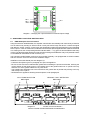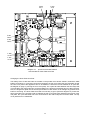
1
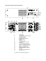
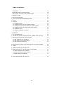
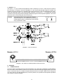
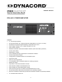
OWNER’S MANUAL
DPA 4410 POWER AMPLIFIER
Features
•
4 x 100 W output capacity
•
off ground potential 100 V outputs (internally configurable to 70 V/50 V or 4 ohms)
•
all outputs are protected against floating (no load) and short-circuit
•
mains supply 115/230 V AC or battery operation 24 V DC
•
mains switch 115/230 V
•
REMOTE CONTROL start with STANDBY indicator (mains and battery operation)
•
service mains switch
•
GROUND-LIFT switch
•
active ventilated through a temperature-controlled DC ventilator
•
electronically balanced inputs
•
routing switch for parallel operation of the amplifier inputs
•
input level control
•
power-on noise suppression
•
3 LED indicators with CLIPPING indicator for metering purposes
•
MONITOR outputs
•
temperature control with PROTECT indicator
•
fault indicators: READY and GROUND FAULT
•
fault message via off potential READY contact
•
TEST switch for pilot tone surveillance and GROUND FAULT reset
•
off ground potential, balanced input transformer are optionally available
•
pilot tone surveillance module and ground fault surveillance module are optionally available
•
19" rack dimensions with 3 HU
17
IMPORTANT SAFETY INSTRUCTIONS
The lightning flash with arrowhead symbol, within an
equilateral triangle is intended to alert the user to the
presence of uninsulated “dangerous voltage” within the
product’s enclosure that may be of sufficient magnitude to
constitute a risk of electric shock to persons.
The exclamation point within an equilateral triangle is
intended to alert the user to the presence of important
operating and maintance (servicing) instructions in the
literature accompanying the appliance.
1.
2.
3.
4.
5.
6.
7.
8.
9.
10.
Read these instructions.
Keep these instructions.
Heed all warnings.
Follow all instructions.
Do not use this apparatus near water.
Clean only with a damp cloth.
Do not block any of the ventilation openings.
Install in accordance with the manufactures instructions.
Do not install near any heat sources such as radiators, heat registers, stoves, or other apparatus
that produce heat.
Only use attachments/accessoris specified by the manufacturer.
Refer all servicing to qualified service personnel. Servicing is required when the apparatus has
been damaged in any way, such as power-supply cord or plug is damaged, liquid has been
spilled or objects have fallen into the apparatus, the apparatus has been exposed to rain or
moisture, does not operate normally, or has been dropped.
For US and CANADA only:
Do not defeat the safety purpose of the grounding-type plug. A grounding type plug has two blades and
a third grounding prong. The wide blade or the third prong are provided for your safety. When the provided
plug does not fit into your outlet, consult an electrican for replacement of the absolete outlet.
IMPORTANT SERVICE INSTRUCTIONS
1. Security regulations as stated in the EN 60065 (VDE 0860 / IEC 65) and the CSA E65 - 94 have to
be obeyed when servicing the appliance.
2. Use of a mains separator transformer is mandatory during maintenance while the appliance is
opened, needs to be operated and is connected to the mains
3. Switch off the power before retrofitting any extensions, changing the mains voltage or the output
voltage.
4. The minimum distance between parts carrying mains voltage and any accessible metal piece
(metal enclosure), respectively between the mains poles has to be 3 mm and needs to be minded
at all times.
The minimum distance between parts carrying mains voltage and any switches or breakers that are
not connected to the mains (secondary parts) has to be 6 mm and needs to be minded at all times.
5. Replacing special components that are marked in the circuit diagram using the security symbol
(Note) is only permissible when using original parts.
6. Altering the circuitry without prior consent or advice is not legitimate.
7. Any work security regulations that are applicable at the location where the appliance is being
serviced have to be strictly obeyed. This applies also to any regulations about the work place itself.
8. All instructions concerning the handling of MOS - circuits have to be observed.
Note:
SAFETY COMPONENT (HAS TO BE REPLACED WITH ORIGINAL PART ONLY)
18
INDICATORS, CONTROLS AND CONNECTIONS
1
2
3
4
5
6
7
8
9
10
11
12
13
14
15
16
17
18
19
20
LED meters
CLIP indicator
TEST button for checking and reset
STANDBY indicator
PROTECT indicator
GROUND FAULT indicator
READY indicator
air inlets
POWER on switch
AC MAINS INPUT connector
mains fuse
VOLTAGE SELECTOR switch
LEVEL 1- 4 input level controls
INPUT 1- 4 XLR-type connectors
INPUT 1- 4 routing switch
REMOTE CONTROL connector
POWER OUTPUT connector
air outlets
CIRCUIT TO CHASSIS switch
DC INPUT 24 V=
A rear plate screws (see also paragraph 11)
19
TABLE OF CONTENTS
FEATURES . . . . . . . . . . . . . . . . . . . . . . . . . . . . . . . . . . . . . . . . . . . . . . . . . . . . . . . . 17
IMPORTANT SAFETY INSTRUCTIONS . . . . . . . . . . . . . . . . . . . . . . . . . . . . . 18
INDICATORS, CONTROLS AND CONNECTIONS . . . . . . . . . . . . . . . . . . . . . . . . . 19
1. GENERAL NOTES . . . . . . . . . . . . . . . . . . . . . . . . . . . . . . . . . . . . . . . . . . . . . . . . . . 21
2. INSTALLATION NOTES . . . . . . . . . . . . . . . . . . . . . . . . . . . . . . . . . . . . . . . . . . . . . . 21
3. PRECAUTIONS AND RECOMMENDATIONS. . . . . . . . . . . . . . . . . . . . . . . . . . . . . 21
4. INPUTS . . . . . . . . . . . . . . . . . . . . . . . . . . . . . . . . . . . . . . . . . . . . . . . . . . . . . . . . . . . 22
5. OUTPUTS . . . . . . . . . . . . . . . . . . . . . . . . . . . . . . . . . . . . . . . . . . . . . . . . . . . . . . . . . 22
5.1
5.2
5.3
5.4
5.5
5.6
POWER OUTPUT. . . . . . . . . . . . . . . . . . . . . . . . . . . . . . . . . . . . . . . . . . . . . . .
POWER OUTPUT with 100 V speaker systems . . . . . . . . . . . . . . . . . . . . . . .
POWER OUTPUT with low impedance speaker systems . . . . . . . . . . . . . . . .
POWER OUTPUT 100 V with double output capacity . . . . . . . . . . . . . . . . . . .
MONITOR output . . . . . . . . . . . . . . . . . . . . . . . . . . . . . . . . . . . . . . . . . . . . . . .
REMOTE CONTROL connection . . . . . . . . . . . . . . . . . . . . . . . . . . . . . . . . . . .
22
23
23
24
24
24
6. METERING . . . . . . . . . . . . . . . . . . . . . . . . . . . . . . . . . . . . . . . . . . . . . . . . . . . . . . . . 25
7. 24 V DC OPERATION . . . . . . . . . . . . . . . . . . . . . . . . . . . . . . . . . . . . . . . . . . . . . . . 25
8. SETTING THE OUTPUT VOLTAGE (only by qualified service personal) . . . . . . . . 25
9. ADDITIONAL FUNCTIONS AND FEATURES . . . . . . . . . . . . . . . . . . . . . . . . . . . . . 26
9.1 NRS 90206 pilot tone surveillance. . . . . . . . . . . . . . . . . . . . . . . . . . . . . . . . . . . 26
9.2 NRS 90207 ground fault surveillance . . . . . . . . . . . . . . . . . . . . . . . . . . . . . . . . 27
9.3 NRS 90208 input transformer . . . . . . . . . . . . . . . . . . . . . . . . . . . . . . . . . . . . . . 27
10. INCORPORATION INTO 19" FLIGHTCASES OR 19" RACK SYSTEMS . . . . . . . 28
11. FUSES . . . . . . . . . . . . . . . . . . . . . . . . . . . . . . . . . . . . . . . . . . . . . . . . . . . . . . . . . . . 28
12. SPECIFICATIONS OF THE DPA 4410 . . . . . . . . . . . . . . . . . . . . . . . . . . . . . . . . . . 30
13. SPECIFICATIONS OF THE OPTIONAL ACCESSORIES . . . . . . . . . . . . . . . . . . . 31
13.1 NRS 90206 pilot tone surveillance. . . . . . . . . . . . . . . . . . . . . . . . . . . . . . . . . . 31
13.2 NRS 90207 ground fault surveillance . . . . . . . . . . . . . . . . . . . . . . . . . . . . . . . 31
13.3 NRS 90208 input transformer . . . . . . . . . . . . . . . . . . . . . . . . . . . . . . . . . . . . . 31
14. BLOCK DIAGRAM OF THE DPA 4410 . . . . . . . . . . . . . . . . . . . . . . . . . . . . . . . . . . 48
20
1. GENERAL NOTES
The amplifier DPA 4410 has been specially designed to ensure durable performance and reliable
operation of sound reinforcement systems with several independent speaker circuits. The DPA 4410 is
best suited for call and message transmission installations, alert systems, and for general music
applications in industrial enterprises, offices, multi-functional halls and sports arenas, schools, churches,
hotels, hospitals, supermarkets, cruise ships, and other similar occasions.
2. INSTALLATION NOTES
When placing or mounting the amplifier, it is important that the air-flow can pass unhindered through the
air inlets on the front and the air outlets on the rear of the appliance (see also paragraph 10).
The amplifier has to be protected from:
- dropping or splashing water
- direct sunlight
- high environmental temperatures or direct radiation of heat sources
- moisture
- dust
- shock or vibration
When moving the amplifier from a cold into a warm environment, condensation of its inner parts can
sometimes occur. If so, the appliance can be operated again after gaining the environmental temperature
(approximately after one hour).
If a solid object has fallen or liquid has leaked into the device, disconnect all connections and get in contact
with an authorized DYNACORD service center. Do not operate the amplifier after such accidents.
When cleaning the amplifier’s outside enclosure, never use any cleaning sprays or detergents, because
of inflamability. The use of those liquids will damage the appliance.
3. PRECAUTIONS AND RECOMMENDATIONS
When the appliance is operated with the mains supply, use the included mains cable to connect the
amplifier to a 230 V or 115 V 50/60 Hz wall outlet. Connect the cable’s other end to the appliance’s 3-pole
machine-type socket (10).
Warning
The amplifier is factory-set to 230 V AC. To change this setting use the voltage switch
(12). For the operation with 115 V AC, the mains fuse (11) has to be exchanged by an
8 A slow-blow fuse with the label print “T8A” (see also paragraph 11).
When using the amplifier with a remote-start device, an external 24 V DC source has to be connected to
the REMOTE CONTROL connector (16) (see also paragraph 5.6). If the connection was performed right
and 24 V DC voltage is present, the STANDBY indicator (4) will light.
The POWER switch (9) on the rear of the amplifier for bridging the starting relay is meant only for service
purposes. In that case the amplifier can be operated without the external 24 V DC supply.
Note
The POWER switch (9) on the rear of the amplifier is meant only for service purposes. If this
switch is engaged, the remote power-off function of the appliance is not operational and the
STANDBY indicator provides no indication.
The DPA 4410 is equipped with a cut-in delay of approximately 3 seconds to efficiently suppress
power-on noise.
21
4. INPUTS 1 - 4
The inputs 1 - 4 (14) are electronically balanced. With a sensitivity of 775 mV = 0 dB, they are meant for
the connection of common control pre-amplifiers. In case off ground potential inputs are needed, the
amplifier inputs are prepared to be retrofitted with input transformers of the type NRS 90208 (per input).
Using the ROUTING switch (15) allows parallel operation of the inputs 1 - 4, providing the through
connection of the input signal, when feeding the identical program to several power amplifiers. The correct
input level can be set by using the level controls (13).
Hinweis
Visual determination of the ROUTING switches’
required settings can be established by marking the
corresponding symbols, located next to the switches,
using a permanent maker.
ROUTING Switch
ON
OFF
Diagram 1 Input connections
Diagram 2 NF cable for coupled operation of two DPA 4410
5. OUTPUTS
5.1
POWER OUTPUT
All power outputs are balanced and off ground potential. The outputs are presetted by DYNACORD for
the connection of 100 V speaker systems. The connection is achieved through plugging the 8-pole socket
into the connection strip (17). Using the output transformer switch, the output voltage can be changed to
70 V, 50 V and 20 V (see also paragraph 8). In the 20 V position, the operation of low impedance speakers
with a load of 4 ohms is possible.
22
5.2
POWER OUTPUT with 100 V speaker systems
The use of speaker systems with a 100 V matching transformer is recommended to reduce the lack in
performance when the distance between amplifier and speaker systems exceeds 50 m. This method also
offers an easy way of output power distribution. The total power consumption of the maximum amount of
the connected speaker network has to match the amplifier’s overall output capacity of 100 W (with an
impedance of 100 ohms). The connection is performed via the 100 V output (17) (see also diagram 3).
Diagram 3 Connecting 100 V (70 V or 50 V) speakers
5.3
POWER OUTPUT with low impedance speaker systems
After switching the output to 20 V, low impedance speaker systems (4 - 16 ohms) can be connected to
the corresponding output (see also diagram 4). Because of an occurring drop in the overall performance,
the distance between amplifier and speaker systems should not exceed 50 m. It is of further importance
that the overall impedance of the speakers does not decline 4 ohms and that the individual power handling
capacity of each speaker is not exceeded.
Free combination of the DPA 4410’s power output voltages, including mixed 100 V and low impedance
(4 ohms) operation, is possible.
Diagram 4 Connecting low impedance speakers
23
5.4
POWER OUTPUT 100 V with double output capacity
If the output power of one output is not sufficient to feed all cabinets that are incorporated within a speaker
network and it is not possible to divide the speaker chain, doubling the output power can be achieved by
coupling the outputs of two DPA 4410. In that case the amplifier inputs are paralleled and the outputs are
connected in series (see also diagram 5).
Coupling is possible under the following restrictions: only identical amplifiers can be connected. Since
doubling the output voltage comes along with the serial connection, it is necessary to switch the outputs
of both amplifiers to 50 V (see also paragraph 8), resulting again in 100 V overall output voltage. In this
case the speaker chain’s minimum load impedance is 50 ohms. The LEVEL controls (13) of the two DPA
4410 have to be set fully to the right.
This procedure results in the following output combinations:
4 x 100 W or 2 x 100 W + 1 x 200 W or 2 x 200 W
For information about the input connection, please refer to paragraph 4 of this manual. For the connection
of the speaker network, please refer to the diagram below.
Attention
During the operation the pins of the POWER OUTPUT strip may conduct dangerous
voltage (> 34 V in peaks). Therefore, the connected speaker networks have to be
installed in accordance to applicable security regulations (see also paragraph 9.2).
Diagram 5 Connecting 100 V speakers with a power increase to 200 V
5.5
MONITOR output
The MONITOR outputs (16) provide an unbalanced, low-impedance signal and are meant for the
connection of monitoring amplifiers. Since the outputs are of low impedance, the cable length of the
connected speaker systems may be up to 200 m. Connection is performed via the REMOTE CONTROL
D-Sub connector (see also diagram 6).
5.6
REMOTE CONTROL connection
The following control IN/OUTs are provided through the 15-pole D-Sub REMOTE CONTROL connector
(16):
- 24 V standby voltage
- POWER REMOTE start
- BATTERY REMOTE start
- MONITOR output
- READY message
- negative pole grounded
- closing contact over ground
- closing contact over ground
- single-sided grounding
- off potential contact
24
1
+24V = Standby
2
⊥ Standby ground
3
power remote
4
battery remote
5
⊥ monitor ground
6
monitor 3
9
⊥ monitor ground
10 monitor 1
11
12
13
14
7
8
15
⊥ monitor ground
monitor 2
⊥ monitor ground
monitor 4
ready
Diagram 6 Pin-assignment of the REMOTE CONTROL D-Sub connector
6. METERING
The green LED indicator (1) permits the continuous monitoring of the output level, providing the possibility
to prevent the speaker systems from overload situations and damaging. When during program peaks the
red CLIP LED (2) lights briefly, the maximum distortion-free output is gained. Whenever the CLIP LED
(2) is continuously lit, the amplifier is driven into overdrive and the input level should be reduced.
7. 24 V DC OPERATION
The DPA 4410 can be operated on the mains power supply or fed by an external 24 V battery.
Switching to battery operation is performed through an internal relay.
The battery is connected to the socket on the rear of the appliance (20), using insulated AMP flat
connectors 6.3 x 0.8 mm. The amplifier is protected against the confusion of poles. Additional internal
protection is provided by two 25 A miniature fuses, located on the printed board assembly 85264 (see
also diagram 10).
The battery cable’s cross section should be at least 2.5 mm2 and the length of the cable should not exceed
4.0 m (max. drop in voltage <1 V).
Attention. The DPA 4410 can only be operated using batteries without grounding or batteries with
grounding of the negative pole. Operation with batteries with grounding of the positive
pole is not possible.
8. SETTING THE OUTPUT VOLTAGE (only by qualified service personal)
The DPA 4410 provides output voltages of either 20 V, 50 V, 70 V, or 100 V. The output voltage is preset
to 100 V. Changing the output voltage to a value of 20 V, 50 V, or 70 V should only be carried out by
authorized DYNACORD service personal.
Attention
During the operation the pins of the POWER OUTPUT strip may conduct dangerous
voltage (> 34 V in peaks). Therefore, the connected speaker networks have to be
installed in accordance to applicable security regulations (see also paragraph 9.2).
- To open the appliance remove the top plate.
- The four output transformers 354030 are located on the left-hand side of the appliance. They are
numbered 1, 2, 3, and 4; starting from the rear cover plate of the appliance.
- Before switching an output, the corresponding transformer has to be removed. This is done by detaching
the screws on the bottom plate of the appliance.
- For changing the output voltage (see also diagram 7), the orange wire on the transformer attached to
the soldering tab 13 (100 V) has to be unsoldered and soldered instead to the required soldering tab
(70 V, 50 V, or 20 V).
- The output transformer as well as the screws on the bottom plate have to be replaced at the same spot.
- The top cover plate of the appliance has to be replaced.
25
20 V
50 V
100 V
70 V
Diagram 7 Changing the output transformer’s 354030 output voltage
9. ADDITIONAL FUNCTIONS AND FEATURES
9.1
NRS 90206 pilot tone surveillance
Using the extension kit NRS 90206, the amplifier channels are automatically and continuously monitored.
This is achieved by sending an ultra low-level 19 kHz pilot tone through the device. It enters the signal
path after the LEVEL controls, runs through the amplification stages and gets filtered out and evaluated
at the output. In case the result of this evaluation shows that the pilot dropped beneath a defined threshold
or is missing at all, the corresponding READY indicator AMP 1 - 4 (7) goes out and the READY fault relay
is reset. The fault message appears as collective fault message at the READY relay’s off-potential contact
on the REMOTE CONTROL D-Sub connector (16).
The extension kit NRS 90206 comes as a plug-in board assembly. It is equipped with a 19 kHz oscillator
and four selective 19 kHz receivers with evaluation stages.
Installation of the NRS 90206 (see also diagram 8):
- Follow the descriptions given in paragraph 8 to open the appliance
- Be sure to first insert the included board-guides before installing the printed circuit board, assuring the
correct position of their guide grooves. The release lever of the guides marked as “A” points to the top,
while the one of the guides marked as “B” points down.
- The printed board assembly has to be inserted into the guides with its printed side pointing to the top,
until it firmly locks in place.
- Reassemble the appliance following the descriptions under paragraph 8.
PILOT TONE DETECTION
NRS 90206
A
GROUND FAULT DETECTION
NRS 90207
B
C
Diagram 8
Printed circuit board 89018.1
with the inserted modules NRS 90206 and NRS 90207
26
D
Checking the functioning:
With built-in NRS 90206 and operational amplifier, the READY indicators (7) have to be lit. Use the TEST
button (3) to check and reset the pilot function. When keeping the TEST button pressed, the 19 kHz
oscillator is switched off, the READY indicators go out, and the READY fault relay is being reset. After
approximately 3 seconds, when the TEST button is released, the READY indicators will light again.
9.2
NRS 90207 ground fault surveillance
The VDE regulation DIN VDE 0800 has to be obeyed when planning and afterwards operating 100 V
sound reinforcement systems. Especially 100 V alert systems have to be in accordance with all protection
measures for class 3 appliances.
Therefore, we recommend for off-ground potential speaker network installations the use of the ground
fault surveill ance module NRS 90207 for automated surveillance of the network insulation. Error
registration: A ground fault message signals that a damaged cable has been detected – possibly resulting
in an upcoming cable interruption – or a wrongly connected cable, possibly resulting in malfunctioning.
Whenever the DPA 4410 is operational or connected to an intact battery, the message “Ground Fault” is
given out even with short-time ground fault occurrences (>5 sec). The ground fault message appears as
collective fault message at the READY relay’s off-potential contact on the REMOTE CONTROL D-Sub
connector (16).
The extension kit NRS 90207 comes as a plug-in printed board assembly, providing monitoring circuitry
with error-storage and display driver for four 100 V outputs.
Installation of the NRS 90207 (see also diagram 8):
- Follow the descriptions given in paragraph 8 to open the appliance.
- Be sure to first insert the included board-guides before installing the printed circuit board, assuring the
correct position of their guide grooves. The release lever of the guides marked as “C” points to the top,
while the one of the guides marked as “D” points down.
- The printed circuit board has to be inserted into the guides with its printed side pointing to the top,
until it firmly locks in place.
- Reassemble the appliance following the descriptions under paragraph 8.
Checking the functioning:
With built-in NRS 90207 and operational amplifier, the READY indicators (7) have to be lit. When using
an external switch to shortcut one pole of the 100 V speaker network via a 47 kohms resistor and the
ground conductor, the GROUND FAULT indicator (6) has to light and the READY fault relay has to reset.
After releasing the button, the messages has to stay present. Use the TEST button (3) to reset the ground
fault surveillance function.
9.3
NRS 90208 input transformer
The DPA 4410 is prepared for the installation of the optional input transformer NRS 90208. In case
off-ground potential inputs are needed, one NRS 90208 has to be installed per input channel.
Installation of the NRS 90208 (see also diagram 8):
- Follow the descriptions given in paragraph 8 to open the appliance.
- Follow the descriptions given in paragraph 11 (exchange of the fuses F502 and F503) to detach the rear
cover plate.
- Detaching the input printed circuit board 81330.1:
first disconnect the four flat cables and then detach the screws of the input sockets.
- Before inserting the input transformer make sure to unsolder the resistors for: T101 : R101/R102, for
T102 : R121/R122, for T103 : R141/R142, and for T104 : R161/R162.
- Attach the input transformer onto the printed circuit board, so that the markings on both parts are
alligned.
- For the re-installation of the printed circuit board follow the same steps as mentioned above; just in the
opposite order.
- To attach the rear cover plate follow the descriptions given in paragraph 11.
- Close the appliance in accordance with the descriptions in paragraph 8.
27
T101
INPUT 1
T104
INPUT 4
T102
INPUT 2
T103
INPUT 3
TO AMP_A
PCB 84167
Diagram 9
10.
TO REMOTE CONTROL
PCB 81330.2
TO AMP_B
PCB 84167
Printed circuit board 81330.1 with inserted input transformers NRS90208
INCORPORATION INTO 19" FLIGHTCASES OR 19" RACK SYSTEMS
Note
Do not operate the DPA 4410 without its enclosure or without parts of the enclosure.
When incorporating the DPA 4410 into a 19" flightcase or 19" rack system make sure, that there is sufficient
air-flow. Between the amplifier’s rear plate and the back-wall of the surrounding enclosure there has to
be at least a space of 60 mm x 330 mm up to the enclosures ventilation gaps. Above the rack system
should be at least a space of 100 mm for a sufficient circulation of the air. During the operation of the DPA
4410 the environmental temperature within the rack closet may increase by about 10° C. This has to be
taken into consideration when installing other equipment into the same rack system or other enclosures.
Note
11.
For trouble-free operation of the appliance, the maximum environmental temperature should
not exceed +40° C.
FUSES
location
pos.
used for
value
dimensions
standard
fuse switch (11)
fuse switch (11)
PCB 85264.2
PCB 85264.2
PCB 85264.2
PCB 85264.2
PCB 85264.2
PCB 85264.2
F501
F501
F502
F503
F504
F505
F506
F507
mains fuse 230V~ AC
mains fuse 115V~ AC
battery fuse 24V DC
battery fuse 24V DC
power-AMP 1
power-AMP 2
power-AMP 3
power-AMP 4
T4A 250V
T8A 250V
25A 32V
25A 32V
T6.3A 250V
T6.3A 250V
T6.3A 250V
T6.3A 250V
5 x 20 mm
5 x 20 mm
flat-type fuse
flat-type fuse
5 x 20 mm
5 x 20 mm
5 x 20 mm
5 x 20 mm
IEC 127
IEC 127
DIN 72581-3
DIN 72581-3
IEC 127
IEC 127
IEC 127
IEC 127
28
F 503
25 A
F 502
25 A
F 504
T6.3A
F 505
T6.3A
F 506
T6.3A
F 507
T6.3A
Diagram 10
printed circuit board 85264.2
with inserted DC fuses F502 and F507
Changing the fuses F502 and F503:
The battery fuses F 502 and F503 are located on the printed circuit board 85264.2, behind the AMP
battery connections. In case they need to be exchanged, the top cover plate (see also paragraph 8) and
the rear cover plate of the appliance have to be detached. Unlock the screws marked as “A” (see also
the diagram on page 2, picturing the rear cover plate). The 4-pole flat cable between the two relays that
is connected to the male multi-point connector B502 on the printed circuit board has to be disconnected.
Now, the hinged rear plate can be turned up and taken out. Be careful not to damage any printed circuit
board or the wiring. The fuses F502 and F503 are now easy to get to (see also diagram 10). Follow the
same procedure in the opposite order to reattach the rear cover plate. After tightening the screws of the
rear plate, the 4-pole flat cable has to be reconnected to the male multi-point connector B502. The top
cover plate has to be reattached.
29
12.
SPECIFICATIONS OF THE DPA 4410
Mains supply:
Voltage:
Frequency:
Protection class:
115 V / 230 V~ AC, ±10
50 - 60
I
mains supply
Umains [V]
Imains [A]
Pmains [VA]
Pmains [W]
Pout [W]
Pv [W]
floating
normal operation (-10 dB)
alert (-3 dB)
normal operation
230
230
230
230
0.27
1.64
3.25
4.39
62
377
748
1010
35
275
585
815
0
40
200
400
35
235
385
415
starting current
< 36 A
mains supply
Umains [V]
Imains [A]
Pmains [VA]
Pmains [W]
Pout [W]
Pv [W]
floating
normal operation (-10 dB)
alert (-3 dB)
normal operation
115
115
115
115
0.54
3.28
6.50
8.78
62
377
748
1010
35
275
585
815
0
40
200
400
35
235
385
415
starting current
< 20 A
Pmains [VA]=apparent power Umains*Imains, Pmains [W]=true power, Pout [W]=output power
Pv [W]=leakage power
Battery supply:
Voltage:
24 V DC, -10/+30 %
battery supply
UB [V]
IB [A]
Pi [W]
Pout [W]
Pv [W]
floating
normal operation (-10 dB)
normal operation
24
24
24
1.0
7.5
18
24
180
432
0
40
250
24
140
182
starting current
< 3.9 A
Pi [W]=input power UB*IB,
Pout [W]=output power, Pv [W]=leakage power
Input characteristics:
Nominal input level
Power output characteristics:
Nominal output power
with mains supply
Nominal output voltage
with mains supply
Nominal load impedance
electronically balanced
775 mV = 0 dBu / 10 kohms
balanced, off ground potential
4 x 100 W ( IEC 268-3)
100 V (70 V / 50 V / 20 V)
100 ohms (50 / 25 / 4 ohms)
minimal total impedance
100 W Output capacity
100 V Output
70 V Output
50 V Output
20 V Output
200 W Output capacity
100 Ohm / 250 nF
50 Ohm / 500 nF
25 Ohm / 1000 nF
4 Ohm/ 6250 nF
50 V + 50 V Output
———
———
———
50 Ohm / 500 nF
———
———
———
≤ -56 dBu
≤1%
60 Hz … 20 kHz
Noise voltage (A-weighted)
THD at PA nominal
Overall frequency response
Distortion-limited response
(PA nominal -3 dB, k∑ = 1 %)
Crosstalk between two channels
60 Hz … 5 kHz
≥ 80 dB at 1 kHz / ≥ 60 dB at 10 kHz
30
Monitor output characteristics:
Nominal output voltage
Nominal load impedance
Overall frequency response
unbalanced
2 V = +8.2 dBu
600 ohms
60 Hz … 20 kHz
Environmental temperature
+5° C … +40° C
Technical regulations:
This appliance is in accordance
with the following regulations:
EN 50081-1, EN 50082-1, EN 60065
Dimensions (W x H x D)
installation depth
without external connectors
installation depth
with external connectors
Weight
Colour
19" (483 mm) x 3 HU (132 mm) x 345 mm
340 mm
max. 400 mm
22.3 kg
anthracite
Optional accessories for the DPA 4410:
NRS 90206 pilot tone surveillance module (for four outputs)
NRS 90207 ground fault surveillance module (for four outputs)
NRS 90208 balanced input transformer module (for one input)
13.
SPECIFICATIONS OF THE OPTIONAL ACCESSORIES
13.1
NRS 90206 pilot tone surveillance module (for four outputs)
Pilot tone frequency
Error detection threshold
Error message output
13.2
19 kHz ±1 %
≤ 12 mV
collective fault message with READY relay
NRS 90207 ground fault surveillance module (for four outputs)
Input
Error message output
Disruptive strength
Error detection threshold
13.3
speaker line 20 V / 50 V / 70 V / 100 V
collective fault message with READY relay
1000 Veff
≤ 50 kohms
NRS 90208 balanced input transformer module (for one input)
Response
Input impedance
Floating transformation ratio
Primary winding resistance
Secondary winding resistance
20 Hz … 20 kHz
≥ 10 kohms
1:1
1420 ohms at 20° C
1420 ohms at 20° C
31