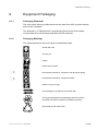
1
TT1222 MPEG-2 SD 4:2:0 Professional
Receiver
Software Version 6.1.1 (and later)
USER GUIDE
EN/LZT 790 0002/1 R1A
TT1222 MPEG-2 SD 4:2:0 Professional Receiver
Copyright
© Copyright Ericsson AB 2010. All rights reserved.
Disclaimer
No part of this document may be reproduced in any form without the written
permission of the copyright owner.
The contents of this document are subject to revision without notice due to
continued progress in methodology, design and manufacturing. Ericsson shall have
no liability for any error or damage of any kind resulting from the use of this
document.
Customer Services
Europe, Middle East
and Africa
Tel:
+44 (0) 23 8048 4455
Fax: +44 (0) 23 8048 4467
Email: [email protected]
Americas
Tel:
Tel:
Fax:
Email:
Email:
+888 671 1268
+678 812 6255
+678 812 6262
[email protected]
[email protected]
US and Canada
International
China
Tel:
Fax:
Tel:
Fax:
Email:
+86 10 8476 8676
+86 10 8476 7741
+852 2590 2388
+852 2590 9550
[email protected]
Beijing
Beijing
Hong Kong
Hong Kong
Australia and New
Zealand
Tel:
+612 (0) 9111 4027
Fax: +612 (0) 9111 4949
Email: [email protected]
Internet Address
www.ericsson.com
Compression
Software Support Centre
Technical Training
International
Tel:
+44 (0) 23 8048 4229
Fax: +44 (0) 23 8048 4161
Email: [email protected]
Trademark List
2 (20)
Dolby®/AC-3®
Registered trademarks of Dolby Laboratories Licensing Corp.
Ethernet®
is a registered trademark of Xerox Corporation.
EN/LZT 790 0002/1 R1A 2011-02-21
Contents
Contents
1
1.1
1.2
1.3
1.4
Introduction............................................................................................ 5
Who Should Use this User Guide? .......................................................... 5
What Equipment is Covered by this User Guide? ................................... 5
Hardware Options.................................................................................... 6
Software Options ..................................................................................... 6
2
2.1
2.2
2.3
2.4
2.5
Installing the Equipment ....................................................................... 7
Introduction.............................................................................................. 7
Operating Voltage.................................................................................... 7
Power Cable and Earthing....................................................................... 7
Connecting Up the Basic Receiver .......................................................... 8
Connecting the Receiver to the Power Supply ...................................... 10
3
3.1
3.2
Operating the Equipment from the Front Panel................................ 11
Introduction............................................................................................ 11
Navigating the Menus ............................................................................ 11
4
4.1
4.2
4.3
4.4
4.5
Typical Operation and Setting of Parameters................................... 13
Setting up the QPSK Input Menu (if Option Card fitted) ........................ 13
Setting up the ASI Input Menu (If Option Card fitted) ............................ 13
Setting Up a TV Service ........................................................................ 13
Setting Up Audio 2 Service.................................................................... 14
Set the Default Output Options.............................................................. 14
5
Typical Configurations........................................................................ 16
6
Equipment Packaging ......................................................................... 17
7
7.1
7.2
7.3
Materials Declarations ........................................................................ 18
Overview................................................................................................ 18
For the European Union ........................................................................ 18
For China............................................................................................... 18
8
8.1
8.2
Disposal of this Equipment ................................................................ 19
General.................................................................................................. 19
For the European Union ........................................................................ 19
9
Recycling.............................................................................................. 20
List of Figures
Figure 1
Figure 2
Typical Rear Panel Component Parts and Connectors (TT1222 with
QPSK input option).................................................................................. 8
Navigation Using Arrow Keys ................................................................ 11
List of Tables
Table 1
Table 2
EN/LZT 790 0002/1 R1A 2011-02-21
Equipment Model Descriptions ................................................................ 5
Hardware Options.................................................................................... 6
3 (20)
Contents
Table 3
Table 4
Table 5
4 (20)
Software Options......................................................................................6
Types of Connector ..................................................................................9
Fuse Type and Rating ............................................................................10
EN/LZT 790 0002/1 R1A 2011-02-21
1BIntroduction
1
Introduction
1.1
Who Should Use this User Guide?
This User Guide is written for operators/users of the TT1222 MPEG-2 SD 4:2:0
Professional Receiver to assist in installation and operation. It is not intended to be a
detailed source of information. This can be found in the Reference Guide companion
document which is issued on CD.
Warning!
Do not remove the covers of this equipment. Hazardous voltages are present within
this equipment and may be exposed if the covers are removed. Only Ericsson
trained and approved service engineers are permitted to service this equipment.
Caution!
Unauthorized maintenance or the use of non-approved replacements may affect the
equipment specification and invalidate any warranties.
1.2
What Equipment is Covered by this User Guide?
Ericsson is introducing an improved ordering system for its television products. New
part numbers are being introduced to support this new system.
Table 1 shows the new part numbers used for ordering and supply of the product
and its options.
Table 1
Equipment Model Descriptions
Model Number
TT1222
TT1222 with Russian Secam
Description
1U MPEG-2 SD 4:2:0 Professional Receiver.
As described for TT1222
with
addition of support for
Russian SECAM Video
Output.
Common Interface CA unit with: 2 x Composite
Video Outputs, 2 x Audio Outputs
(D-types), RS-232 Data, RS-232 Remote
Control, 5 x General Purpose Outputs (GPO),
1 x Alarm Relay and
1 x Ethernet Port
Marketing Code
TT1222/CIBAS
TT1222/RSBAS
Price Object Number
FAZ 101 0128/1
FAZ 101 0128/2
Supply Object Number
KDU 137 661/1
KDU 137 661/2
EN/LZT 790 0002/1 R1A 2011-02-21
5 (20)
1BIntroduction
1.3
Hardware Options
See Table 2 for a list of hardware options available with the Receiver. Detailed
information is in the Reference Guide.
Table 2
Hardware Options
Marketing Code
Price Object
Number
Supply Object
Number
Description
TT1222/HWO/QPSK
FAZ 101 0128/8
ROA 128 3846
Single QPSK Input Card
TT1222/HWO/ASI/IN
FAZ 101 0128/9
ROA 128 3847
Single ASI Input Card
TT1222/HWO/ASI/OUT
FAZ 101 0128/10
ROA 128 3848
Single ASI Output Card
TT1222/HWO/ASI/SDI
FAZ 101 0128/11
ROA 128 3849
Dual ASI / SDI Output Card
TT1222/HWO/IP/OUT
FAZ 101 0128/12
ROA 128 3850
Dual IP Output Card
1.4
Software Options
See Table 3 for a list of software options available with the Receiver. Detailed
information is in the Reference Guide.
Table 3
Software Options
Marketing Code
Price Object
Number
Supply Object
Number
Description
TT1222/SWO/AC3
FAZ 101 0128/5
FAT 102 0281
Dolby Digital decoding
TT1222/SWO/DIRV5
FAZ 101 0128/4
FAT 102 0280
Director by Ericsson
6 (20)
EN/LZT 790 0002/1 R1A 2011-02-21
2BInstalling the Equipment
2
Installing the Equipment
2.1
Introduction
For best performance and reliability follow the instructions for site requirements and
installation in the Reference Guide and only use installation accessories
recommended by the manufacturers.
2.2
Operating Voltage
2.2.1
AC Models
AC models are fitted with a wide-ranging power supply. It is suitable for supply
voltages of 100-240 Vac -10% +6% at 50/60 Hz nominal.
Caution!
This product should be operated only from the type of power source indicated on the
marking label. If you are not sure of the type of power supply to your business,
consult a qualified electrical engineer or your local power company.
Note:
Refer to the Reference Guide for details of the color codes used on the
mains leads.
See Table 5 for fuse information and also the Reference Guide for a full power
supply specification.
2.3
Power Cable and Earthing
Check that the power cable is suitable for the country in which the Receiver is to be
used.
(Power Cable Information: H05VV-F, 0.75mm2, 3G or greater)
EN/LZT 790 0002/1 R1A 2011-02-21
7 (20)
2BInstalling the Equipment
Warnings!
The Technical Earth is not a Protective earth for electric shock protection.
This unit must be correctly earthed through the molded plug supplied. If the local
mains supply does not have an earth conductor do not connect the unit. Contact
Customer Services for advice.
Before connecting the unit to the supply, check the supply requirements in Annex B
of the Reference Guide.
2.4
Connecting Up the Basic Receiver
Always use the specified cables supplied for signal integrity and compliance with
EMC requirements (see the Reference Guide).
The rear panel is directly related to the input and output options fitted. Table 4
describes the types of connectors. Figure 1 shows the typical rear panel
components and connectors.
QPSK In, DC Out
Conditional
Access Interface
CVBS
Output
RS232
Remote
Ethernet
Relay / GPO
Technical
Earth
Audio
Outputs
AC In
RS232 Data
Figure 1
8 (20)
Typical Rear Panel Component Parts and Connectors (TT1222 with
QPSK input option)
EN/LZT 790 0002/1 R1A 2011-02-21
2BInstalling the Equipment
Table 4
Types of Connector
Type of Connector
Description
Inputs
Technical Earth
Connect the Receiver's Technical earth to a suitable point.
RS232 Remote
A 9-way, D-type male connector provides a connection to a
PC for remote control and software upload.
QPSK IN
An F-type female connector provides an L-band input.
(Input Option)
ASI IN
A 75 Ω BNC connector provides an ASI input
(Input Option)
Outputs
CVBS
2 x 75 Ω BNC connectors provide a high quality analogue
composite video output from the unit.
Note:
ASI OUT
Russian SECAM output option uses the
existing CVBS output connectors
A 75 Ω BNC connector provides an ASI output
(Output Option)
(Output Option)
Two 75 Ω BNC connectors provide both ASI and SDI
outputs.
Dual IP OUT
Two RJ-45, female connectors.
Dual ASI / SDI OUT
(Output Option)
Audio 1 and 2
Two 9-way, D-type male connectors.
Audio outputs 1 and 2 are analogue and digital
(simultaneous).
Ethernet
A RJ-45, female connector.
RS232 Data
A 9-way, D-type female connector provides an RS-232
low-speed data output.
Conditional Access
Interface
A single common interface slot, for insertion of the CA
Module.
Relay/GPO
A 9-way, D-type female connector provides a relay and GPO
interface which can be used to send signals to remote
equipment. (1 x Alarm relay and 5 x GPO relays). The GPOs
can be configured to trigger on particular events and the
relay is triggered when any alarm occurs.
EN/LZT 790 0002/1 R1A 2011-02-21
9 (20)
2BInstalling the Equipment
2.5
Connecting the Receiver to the Power Supply
Warnings!
Do not overload wall outlets and extension cords as this can result in a risk of fire or
electric shock.
As no mains switch is fitted to this unit, ensure the local power supply is switched
OFF before connecting the supply cord.
The Receiver is not fitted with an on/off switch. Ensure that the socket-outlet is
installed near the equipment so that it is easily accessible. Failure to isolate the
equipment properly may cause a safety hazard.
Connect the Receiver to the power supply as follows:
•
Power Supply
Ensure the power supply is isolated and switched off.
•
Receiver
Ensure the correct fuse type and rating has been fitted to both the equipment
and the power cable.
•
Supply Cord
Connect the lead to the Receiver input connector and then to the power supply.
Switch on the power supply.
Table 5
Power Supply
Fuse Type and Rating
100-240 V AC –10% +6% at
50/60 Hz nominal
5 x 20 mm
IEC/EN 60127-2 Sheet 2
Hollyand 5OF or Littelfuse 617
F3.15 A 250 V
Note:
10 (20)
Fuse Type and Rating
The Internal fuse is not user replaceable
Refer to the Reference Guide for all power supply, fuse, safety, EMC
information and operating conditions.
EN/LZT 790 0002/1 R1A 2011-02-21
3BOperating the Equipment from the Front Panel
3
Operating the Equipment from the Front Panel
3.1
Introduction
The front panel display and keypad may be used to configure, control and monitor
the unit when an external control system is not used.
3.2
Navigating the Menus
3.2.1
Navigation Using Arrow Keys
Move cursor up /
scroll up
Return to
previous
menu
Increment value
Select item at
cursor
Decrement value
Move cursor down /
scroll down
Navigating the Menus
Figure 2
Note:
Position
Cursor
Position
Cursor
Editing Values in a Menu
Navigation Using Arrow Keys
The Arrow keys are referred to as Left, Right, Up and Down, indicating
the direction of the arrows
3.2.2
Selecting a (Sub) Menu Item
3.2.2.1
Selecting the Menu Item
To select a menu item, navigate using the Up and Down arrow keys until the
desired menu is displayed in front of the cursor. Press the Right arrow key to
select / enter this menu item.
3.2.2.2
Leaving the Menu Item
To leave the current menu tree, press the Left arrow key.
EN/LZT 790 0002/1 R1A 2011-02-21
11 (20)
3BOperating the Equipment from the Front Panel
3.2.3
Editing a Menu Value
3.2.3.1
Accessing the Edit Mode
To edit a menu item, first select the item using the Right arrow key. This takes you
from the select mode to the edit mode.
3.2.3.2
Editing a Selectable Option
Once in edit mode, use the Up and Down arrow keys until the desired value is
displayed. Exit and save the selection by pressing the Right arrow key. To exit
without saving, press the Left arrow key.
3.2.3.3
Editing an Alphanumerical Value
When editing an alphanumerical value, the cursor starts flashing underneath the
rightmost digit, once entering the edit mode. Use the Up and Down arrow keys to
increase or decrease the value of this digit. Press the Left arrow key to select the
next digit. The cursor moves to underneath the neighboring digit.
Again, use the Up and Down arrow keys to increase or decrease the value of this
digit. Once satisfied with the result, move the cursor outside the selectable digits, by
pressing the Right arrow key several times. Once the cursor moves outside the
selectable area the arrow keys return to navigation mode and the new value is
saved.
12 (20)
EN/LZT 790 0002/1 R1A 2011-02-21
4BTypical Operation and Setting of Parameters
4
Typical Operation and Setting of Parameters
Refer to Section 3.2 onwards on how to navigate the menus. To view the menu
structure and for more detailed information regarding parameters not mentioned in
this User Guide refer to the Reference Guide.
4.1
Setting up the QPSK Input Menu (if Option Card fitted)
The QPSK Input Menu contains all the items that need to be set to achieve a signal
lock on an incoming QPSK Transport Stream.
Navigate to the Input Menu and select the following options:
4.2
•
LNB freq - enter the desired LNB frequency in Gigahertz. This should be set
to match the external LNB.
•
Sat freq - edit the satellite channel frequency 1 in Gigahertz. This sets up the
tuning frequency in the Receiver.
•
Sym rate - enter the symbol rate. This sets up the incoming symbol rate of
the demodulator.
•
Inner Code - select the correct inner code. This sets up the Forward Error
Correction (FEC) rate of the demodulator.
•
LNB volt - select the correct LNB voltage output of the F-connector: Off,
13 V, 18 V.
•
LNB 22 kHz – activate the LNB 22 kHz control signal to the LNB: On or Off.
•
Spec inv – enable or disable the spectrum inversion on the incoming signal:
On, Off or Auto.
Setting up the ASI Input Menu (If Option Card fitted)
No setup is required for the ASI input module.
4.3
Setting Up a TV Service
The TV Service Menu contains the Service list for the currently tuned Transport
Stream. The list also contains a ServiceID item, which allows the user to select the
Service, simply by typing in the correct Service ID. By selecting a Service in the
Service list, the decoder will decode the selected Service.
1
The satellite frequency should be within the area of the LNB frequency
(±950 to 2150 MHz). If the frequency is outside this range, replace the LNB with a higher or lower ranging unit.
EN/LZT 790 0002/1 R1A 2011-02-21
13 (20)
4BTypical Operation and Setting of Parameters
Navigate to the TV Service Menu. Select the following options:
•
Service ID - display or change the service ID for the decoded Service.
•
Service List - press the Up and Down arrows until the selected Service is
displayed. A small check mark is displayed in front of the Service, indicating that
it is selected.
The TV Service Menu also allows the user to select which of the currently selected
Service components are to be decoded. This is relevant for Services with multiple
audio streams associated with the video.
•
4.4
Aud1 Lang - enter the desired three-character ISO 639 language code to select
the correct audio PID for the video Service. If the selected code is not present in
the audio stream, the first audio stream in the PMT table will be decoded.
Setting Up Audio 2 Service
The Audio2 Service Menu contains the Service list for the currently tuned
Transport Stream. The list also contains a ServiceID item, which allows the user to
select the Service by typing in the correct Service ID. By selecting a Service in the
Service list, the decoder will decode the selected Service on the corresponding
audio output.
Navigate to the Audio2 Service Menu. Select the following options:
•
ServiceID - display or change the service ID for the decoded Service.
•
Service List - press the Up and Down arrows until the selected Service is
displayed. A small check mark is displayed in front of the Service, indicating that
it is selected.
The Audio2 Service Menu also allows the user to select which of the available
audio components are to be decoded. This is relevant for services with multiple
audio streams associated with the video.
•
4.5
Aud2 Lang - enter the three-character ISO language code to select the
correct audio PID for the selected audio Service.
Set the Default Output Options
The Setup Menu contains all the submenus and items, required to set the
configuration and control the daily use of the unit.
Navigate to the Video Setup Menu under Setup and change the preferred video
format to be used when the unit is not decoding video. 2
Select the following options:
2
The Videoformat selection is not a format converter. The video format of the incoming MPEG stream overrides this setting.
14 (20)
EN/LZT 790 0002/1 R1A 2011-02-21
4BTypical Operation and Setting of Parameters
•
Line Standard - change the default line standard to be used when the unit is
not decoding video: 525 or 625 selectable.
•
525 Video - change the preferred 525 video format to be used when the unit
is not decoding video: NTSC, PALM selectable.
•
625 Video - change the preferred 625 video format to be used when the unit
is not decoding video: PAL, PALCN, SECAM selectable.
EN/LZT 790 0002/1 R1A 2011-02-21
15 (20)
5BTypical Configurations
5
Typical Configurations
It may also be necessary to modify some of the other default settings to suit the
particular installation, see the Reference Guide for details.
16 (20)
EN/LZT 790 0002/1 R1A 2011-02-21
6BEquipment Packaging
6
Equipment Packaging
6.1.1
Packaging Statement
The outer carton and any cardboard inserts are made from 82% recycled material
and are fully recyclable.
The Stratocell ® or Ethafoam 220 ® polyethylene foam inserts can be easily
recycled with other low density polyethylene (LDPE) materials
6.1.2
Packaging Markings
The symbols printed on the outer carton are described below:
Handle with care.
This way up.
Fragile.
Protect from moisture.
See Reference Guide for compliance with directives details.
See Reference Guide for compliance details.
Defines country of origin.
The packaging is reusable per GB 18455-2001.
This symbol guarantees that packaging with this symbol is
recyclable and will be accepted by cardboard recyclers.
Recyclable per GB 18455-2001.
EN/LZT 790 0002/1 R1A 2011-02-21
17 (20)
7BMaterials Declarations
7
Materials Declarations
7.1
Overview
Ericsson products are designed and manufactured in keeping with good
environmental practice. Our component and materials selection policy prohibits the
use of a range of potentially hazardous materials. In addition, we comply with
relevant environmental legislation.
7.2
For the European Union
For product sold into the EU after 1st July 2006, we comply with the EU RoHS
Directive. We also comply with the WEEE Directive.
7.3
For China
For product sold into China after 1st March 2007, we comply with the “Administrative
Measure on the Control of Pollution by Electronic Information Products”. In the first
stage of this legislation, content of six hazardous materials has to be declared
together with a statement of the “Environmentally Friendly Use Period (EFUP)”: the
time the product can be used in normal service life without leaking the hazardous
materials. Ericsson expects the normal use environment to be in an equipment room
at controlled temperatures (around 22°C) with moderate humidity (around 60%) and
clean air, near sea level, not subject to vibration or shock.
Where Ericsson product contains potentially hazardous materials, this is indicated
on the product by the appropriate symbol containing the EFUP. For Ericsson
products, the hazardous material content is limited to lead (Pb) in some solders.
This is extremely stable in normal use and the EFUP is taken as 50 years, by
comparison with the EFUP given for Digital Exchange/Switching Platform in
equipment in Appendix A of “General Rule of Environment-Friendly Use Period of
Electronic Information Products”. This is indicated by the product marking:
50
It is assumed that while the product is in normal use, any batteries associated with
real-time clocks or battery-backed RAM will be replaced at the regular intervals.
The EFUP relates only to the environmental impact of the product in normal use, it
does not imply that the product will continue to be supported for 50 years.
18 (20)
EN/LZT 790 0002/1 R1A 2011-02-21
8BDisposal of this Equipment
8
Disposal of this Equipment
8.1
General
Dispose of this equipment safely at the end of its life. Local codes and/or
environmental restrictions may affect its disposal. Regulations, policies and/or
environmental restrictions differ throughout the world. Contact your local jurisdiction
or local authority for specific advice on disposal.
8.2
For the European Union
"This product is subject to the EU Directive
2002/96/EC on Waste Electrical and Electronic
Equipment (WEEE) and should not be disposed of as
unsorted municipal waste."
EN/LZT 790 0002/1 R1A 2011-02-21
19 (20)
9BRecycling
9
Recycling
Ericsson SA TV Recycling has a process facility that enables customers to return
Old and End-of-Life Products for recycling if it is required.
Ericsson provides assistance to customers and recyclers through our Ericsson and
SATV Recycling eBusiness Portal.
This can be reached at: https://ebusiness.ericsson.net/.
Click on the Login Page then enter:
User id: ETelevision
Password: Television
20 (20)
EN/LZT 790 0002/1 R1A 2011-02-21