1
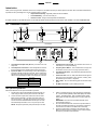
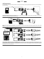
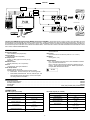
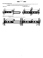
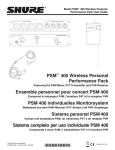
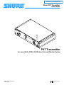
PRODUCT INFORMATION Model P4T Transmitter User Guide P4T Transmitter for use with the PSM 400 Wireless Personal Monitor System 2000, Shure Incorporated 27B8712 (TD) Printed in U.S.A. ENGLISH . . . . . . . . . . . . . . . . . . . . . . . . . . . . . . . . . . . . . . . . . . . . . . . . . . . . . . . . . . . . . . . . . . . . . . . . . . . . . . 3 FRANÇAIS . . . . . . . . . . . . . . . . . . . . . . . . . . . . . . . . . . . . . . . . . . . . . . . . . . . . . . . . . . . . . . . . . . . . . . . . . . . . . 8 DEUTSCH . . . . . . . . . . . . . . . . . . . . . . . . . . . . . . . . . . . . . . . . . . . . . . . . . . . . . . . . . . . . . . . . . . . . . . . . . . . . 13 ESPAÑOL . . . . . . . . . . . . . . . . . . . . . . . . . . . . . . . . . . . . . . . . . . . . . . . . . . . . . . . . . . . . . . . . . . . . . . . . . . . . . 18 ITALIANO . . . . . . . . . . . . . . . . . . . . . . . . . . . . . . . . . . . . . . . . . . . . . . . . . . . . . . . . . . . . . . . . . . . . . . . . . . . . . 23 2 ENGLISH WARNING! USING THIS SYSTEM AT EXCESSIVE VOLUMES CAN CAUSE PERMANENT HEARING DAMAGE. USE AS LOW A VOLUME AS POSSIBLE. In order to use this system safely, avoid prolonged listening at excessive sound pressure levels. Please use the following guidelines established by the Occupational Safety Health Administration (OSHA) on maximum time exposure to sound pressure levels before hearing damage occurs. 90 dB SPL at 8 hours 95 dB SPL at 4 hours 100 dB SPL at 2 hours 105 dB SPL at 1 hour 110 dB SPL at 1/2 hour 115 dB SPL at 15 minutes 120 dB SPL — avoid or damage may occur It is difficult to measure the exact Sound Pressure Levels (SPL) present at the eardrum in live applications. In addition to the volume setting on the PSM, the SPL in the ear is affected by ambient sound from floor wedges or other devices. The isolation provided by the fit of quality earphones is also an important factor in determining the SPL in the ear. Here are some general tips to follow in the use of this product to protect your ears from damage: 1. Turn up the volume control only far enough to hear properly. 2. Ringing in the ears may indicate that the gain levels are too high. Try lowering the gain levels. 3. Have your ears checked by an audiologist on a regular basis. If you experience wax buildup in your ears, stop using the system until an audiologist has examined your ears. 4. Wipe the earphones with an antiseptic before and after use to avoid infections. Stop using the earphones if they are causing great discomfort or infection. This symbol indicates that there are important operating and maintenance instructions in the literature accompanying this unit. Licensing Statement. A user license may be required for operation. Contact the communications authority in your country for more information. Modifications to Approved Equipment. Changes or modifications not expressly approved by Shure Incorporated could affect compliance with telecommunications standards, thereby voiding the user’s authority to operate this product. 3 ENGLISH Introduction Thank you for buying the P4T Transmitter. The P4T is a component in the PSM 400 family of wireless personal monitors. When used with a P4R Receiver, it provides the many advantages of an in–ear monitoring system, including: Improved Sound Quality - high fidelity without the risk of feedback, Increased Mobility - your mix moves with you, Personal Control - through volume adjustment and MixMode. For further information on the PSM 400 system, see the PSM 400 Wireless Personal Performance Pack User’s Guide, available on the web at www.shure.com. P4T Transmitter Features 1 3 2 4 5 6 Front Panel 7 1. 2. 3. Back Panel Local Earphone Output Jack (1/8 inch): Connects to E1 or E5 earphones. Local Earphone Level Control: This knob adjusts the volume of the local earphone jack’s amplifier. Always listen at low levels. Input Level LEDs: Two vertical strings of four LEDs display the input level of the left and right input channels. The four LEDs on the left display the status of the signal from channel 1 and the four LEDs on the right display the status of the signal from channel 2: LED Signal Status RED (top) Limiter Active YELLOW (middle) Nominal Level GREEN (bottom two) Signal Present 8 9 4. Transmission Frequency LED: This indicates which of the 16 channels (0–9 or A–F) is transmitting. 5. Frequency Select Button: This recessed button changes the transmission channel. (Use a 1/4” plug to press this button.) 6. Front-Mounted Antenna: This permanently attached antenna is break-resistant. 7. LOOP OUT Jacks: Two 1/4” TRS jacks allow the audio signal to pass through the transmitter to other devices, including other transmitters, tape recorders, or amplifiers. 8. INPUT Jacks: Two 1/4” TRS switching jacks are line level audio inputs. 9. DC INPUT Connector: Input for PS40 power cord. 3. Select an operating frequency using the Frequency Select Button. Push the button repeatedly until the LED displays the desired channel. The display flashes. Push and hold the button until the flashing stops to confirm the change (use a 1/4” plug to press the button). IMPORTANT: Never set more than ONE transmitter to the same operating frequency. Once the P4T transmits audio, observe the input level LEDs. If the LEDs consistently illuminate red, decrease the output level of the audio source until the red LEDs flicker occasionally. Set up the P4R receiver as directed in the P4R user’s guide. Make sure that the frequency selected on the receiver matches the frequency selected on the transmitter. Set Up and Operation Follow these directions to set up the transmitter for operation. 1. Plug the power cord into the transmitter’s DC INPUT power connector. Plug the other end of the power cord into a wall outlet. 2. Connect line level outputs of an audio source into the audio INPUTS of the transmitter. Use both of the input jacks for a two-channel source. Use either input jack for a mono source. The P4T transmits in MixMode/stereo if both inputs are used, but automatically transmits in mono if only one input is used. NOTE: All inputs are phantom power protected up to 50 VDC. 4. 5. 4 ENGLISH LOOP Applications The LOOP OUT 1/L and 2/R outputs route the transmitter’s incoming signal to other devices. Use the loop feature of the transmitter in any number of applications, such as the following: ÑÑ ÑÑ ÑÑÑ Ñ P4T Transmitter (back panel) P4R Receiver Floor Monitor Amplifier MIXER Operating Floor Monitors Through a P4T Transmitter: Send an audio signal through the LOOP connectors to a floor monitor amplifier. In this set up, the receiver and the onstage monitors reproduce the same audio. P4T TRANSMITTER (BACK PANEL) MIXER Ñ P4R RECEIVER Making a Recording Through a P4T Transmitter: To record a performance, connect the LOOP outputs to the inputs of a tape deck, DAT, or other recording device. BAND MIX SOLO MIX 1 SOLO MIX 2 SOLO MIX 1 SOLO MIX 3 ÑÑÑÑ AUX 1 AUX 2 AUX 3 BAND MIX P4T TRANSMITTER BAND MIX P4R RECEIVER AUX4 MIXING CONSOLE SOLO MIX 2 BAND MIX P4T TRANSMITTER BAND MIX P4R RECEIVER SOLO MIX 3 BAND MIX P4T TRANSMITTER P4R RECEIVER Operating Multiple PSM Wireless Systems Under MixMode Control: Send a band mix from a mixer to a P4T transmitter, then send the band mix on to other transmitters using the P4T’s LOOP OUT feature. Also send independent monitor mixes or direct outputs to the second channel of each transmitter. The entire band receives the same band mix, while each individual player also hears a solo mix of their own. Use the MixMode control on the P4R receiver to adjust the level between the solo mix and the band mix. 5 ENGLISH BAND MIX MIX OUT 1 MIX OUT 1 (P4M MIX 1) ÑÑÑÑÑ Ñ ÑÑ Ñ ÑÑÑÑÑ ÑÑ BAND MIX MIX OUT 2 (P4M MIX 2) SPLIT OUTPUTS 1–4 MIX OUT P4M BAND MIX P4R RECEIVERS PERSONAL MONITOR MIXER INPUTS 1–4 MIXING CONSOLE P4T TRANSMITTERS (BACK PANELS) MIX OUT 2 BAND MIX Operating Two PSM Wireless Systems Under MixMode Control From a P4M Mixer: Send a band mix from a mixing console to a P4T transmitter, then send the band mix to a second transmitter using the P4T’s LOOP OUT feature. Create an individual mix for each transmitter using the P4M mixer. Send the mix to each transmitter using the P4M’s MIX OUT 1 or MIX OUT 2 outputs. Use the MixMode control on the P4R receiver to adjust the levels between the band mix and the P4M mix (for more information on the P4M Personal Monitor Mixer, see the P4M User’s Guide or the PSM 400 Wireless Personal Performance Pack User’s Guide, available at www.shure.com). Current 250 mA maximum Dimensions 219.2 mm X 43.6 mm X 136.5 mm (8.6 in. X 1.7 in. X 5.4 in.) Net Weight 907.2 g (2 lbs., 0 oz.) SPECIFICATIONS RF Frequency Range 722 to 865 MHz (country dependent) Operating Range 300 feet (environment dependent) RF Output Power 50 mW (+17 dBm) typical conducted (country dependent) Modulation Limiter Internal peak limiter (>10:1 compression) Antenna 1/4 Wavelength, semi-rigid, PCB Mount Power Requirements Operating voltage 14–18 Vdc Supplied with one of the following external power supplies: Model PS40: 120 Vac, 60 Hz input, UL and cUL approvals. CERTIFICATION P4T: Type accepted under FCC Part 74, FCC ID DD4P4T. Certified by IC in Canada under RSS–123. EP4T: Conforms to European Union Directives, eligible to bear CE marking. Type approved under EN 300 422. Meets requirements of European EMC standard ETS 300 445. N 108 Model PS40E, Model PS40UK: 230 Vac, 50/60 Hz input, TUV approval with European CE marking, conforms to European Low Voltage Directive 72/23/EEC. Furnished Accessories Single Mount Rack Bracket . . . . . . . . . . . . . . . . . . . . . . . . . . . . . . . . . . . . . . . . . . . . . . . . . . . . . . . . . . . . . . . . . . . . . . . . . . . . . . . . . . . . . . . . . . . . . . . . 53A8450 Dual Mount Rack Bracket . . . . . . . . . . . . . . . . . . . . . . . . . . . . . . . . . . . . . . . . . . . . . . . . . . . . . . . . . . . . . . . . . . . . . . . . . . . . . . . . . . . . . . . . . . . . . . . . . . 53A8442 Straddle Bars . . . . . . . . . . . . . . . . . . . . . . . . . . . . . . . . . . . . . . . . . . . . . . . . . . . . . . . . . . . . . . . . . . . . . . . . . . . . . . . . . . . . . . . . . . . . . . . . . . . . . . . . . . . . 53A8443 AC Adaptor . . . . . . . . . . . . . . . . . . . . . . . . . . . . . . . . . . . . . . . . . . . . . . . . . . . . . . . . . . . . . . . . . . . . . . . . . . . . . . . PS40 (120V), PS40E (230V), PS40UK (230V) CONNECTORS P4T Audio Inputs (1/L and 2/R) Connector Type: P4T LOOP Outputs (1/L and 2/R) 1/ 4-inch Connector Type: jack (female) TRS Configuration: 1/ 4-inch jack (female) TRS electronically balanced Configuration: electronically balanced Actual Impedance: 20 kΩ Actual Impedance: 20 kΩ Nominal Input Level: –10 dBV/–7.8 dBu Nominal Output Level: –10 dBv/–7.8 dBu Maximum Output Level: +15 dBu Maximum Input Level: +15 dBu Pin Assignments: Pin Assignments: Tip = hot ring = cold sleeve = ground Tip = hot ring = cold sleeve = ground Phantom Power Protection? Phantom Power Protection? Yes Up to 50 VDC Yes Up to 50 VDC 6 ENGLISH RACK MOUNTING THE P4T The P4T features a 1/2-rack chassis specially designed for sturdiness. This eliminates the sagging and bending found in most designs — the brackets and straddle bars ensure that the units will be installed securely. WARNING: Do not torque the screws too tightly, or the chassis may be damaged. 1/ -rack 2 Single Unit Dual-Mounted Units Mounting in an Equipment Rack NOTE: Be sure to use both straddle bars when installing dual units. 7 SHURE Incorporated Web Address: http://www.shure.com 222 Hartrey Avenue, Evanston, IL 60202–3696, U.S.A. Phone: 847-866–2200 Fax: 847-866-2279 In Europe, Phone: 49-7131-72140 Fax: 49-7131-721414 In Asia, Phone: 852-2893-4290 Fax: 852-2893-4055 Elsewhere, Phone: 847-866–2200 Fax: 847-866-2585