1
Reference Manual
Check the Extron Web site (www.extron.com) for updates.
MLC 104 Plus Series
MediaLink® Controllers
68-1443-01 Rev. B
01 09
Precautions
Safety Instructions • English
Warning
This symbol is intended to alert the user of important operating and maintenance
(servicing) instructions in the literature provided with the equipment.
Power sources • This equipment should be operated only from the power source indicated on the product. This
equipment is intended to be used with a main power system with a grounded (neutral) conductor. The
third (grounding) pin is a safety feature, do not attempt to bypass or disable it.
This symbol is intended to alert the user of the presence of uninsulated dangerous
voltage within the product’s enclosure that may present a risk of electric shock.
Power disconnection • To remove power from the equipment safely, remove all power cords from the rear of
the equipment, or the desktop power module (if detachable), or from the power source receptacle (wall
plug).
Caution
Read Instructions • Read and understand all safety and operating instructions before using the equipment.
Retain Instructions • The safety instructions should be kept for future reference.
Follow Warnings • Follow all warnings and instructions marked on the equipment or in the user
information.
Avoid Attachments • Do not use tools or attachments that are not recommended by the equipment
manufacturer because they may be hazardous.
Consignes de Sécurité • Français
Power cord protection • Power cords should be routed so that they are not likely to be stepped on or pinched by
items placed upon or against them.
Servicing • Refer all servicing to qualified service personnel. There are no user-serviceable parts inside. To
prevent the risk of shock, do not attempt to service this equipment yourself because opening or removing
covers may expose you to dangerous voltage or other hazards.
Slots and openings • If the equipment has slots or holes in the enclosure, these are provided to prevent
overheating of sensitive components inside. These openings must never be blocked by other objects.
Lithium battery • There is a danger of explosion if battery is incorrectly replaced. Replace it only with the
same or equivalent type recommended by the manufacturer. Dispose of used batteries according to the
manufacturer’s instructions.
Avertissement
Ce symbole sert à avertir l’utilisateur que la documentation fournie avec le matériel
contient des instructions importantes concernant l’exploitation et la maintenance
(réparation).
Alimentations• Ne faire fonctionner ce matériel qu’avec la source d’alimentation indiquée sur l’appareil. Ce
matériel doit être utilisé avec une alimentation principale comportant un fil de terre (neutre). Le troisième
contact (de mise à la terre) constitue un dispositif de sécurité : n’essayez pas de la contourner ni de la
désactiver.
Ce symbole sert à avertir l’utilisateur de la présence dans le boîtier de l’appareil
de tensions dangereuses non isolées posant des risques d’électrocution.
Déconnexion de l’alimentation• Pour mettre le matériel hors tension sans danger, déconnectez tous les cordons
d’alimentation de l’arrière de l’appareil ou du module d’alimentation de bureau (s’il est amovible) ou
encore de la prise secteur.
Attention
Lire les instructions• Prendre connaissance de toutes les consignes de sécurité et d’exploitation avant
d’utiliser le matériel.
Conserver les instructions• Ranger les consignes de sécurité afin de pouvoir les consulter à l’avenir.
Respecter les avertissements • Observer tous les avertissements et consignes marqués sur le matériel ou
présentés dans la documentation utilisateur.
Eviter les pièces de fixation • Ne pas utiliser de pièces de fixation ni d’outils non recommandés par le
fabricant du matériel car cela risquerait de poser certains dangers.
Protection du cordon d’alimentation • Acheminer les cordons d’alimentation de manière à ce que personne ne
risque de marcher dessus et à ce qu’ils ne soient pas écrasés ou pincés par des objets.
Réparation-maintenance • Faire exécuter toutes les interventions de réparation-maintenance par un technicien
qualifié. Aucun des éléments internes ne peut être réparé par l’utilisateur. Afin d’éviter tout danger
d’électrocution, l’utilisateur ne doit pas essayer de procéder lui-même à ces opérations car l’ouverture ou le
retrait des couvercles risquent de l’exposer à de hautes tensions et autres dangers.
Fentes et orifices • Si le boîtier de l’appareil comporte des fentes ou des orifices, ceux-ci servent à empêcher
les composants internes sensibles de surchauffer. Ces ouvertures ne doivent jamais être bloquées par des
objets.
Lithium Batterie • Il a danger d’explosion s’ll y a remplacment incorrect de la batterie. Remplacer uniquement
avec une batterie du meme type ou d’un ype equivalent recommande par le constructeur. Mettre au reut les
batteries usagees conformement aux instructions du fabricant.
Sicherheitsanleitungen • Deutsch
Vorsicht
Dieses Symbol soll dem Benutzer in der im Lieferumfang enthaltenen
Dokumentation besonders wichtige Hinweise zur Bedienung und Wartung
(Instandhaltung) geben.
Stromquellen • Dieses Gerät sollte nur über die auf dem Produkt angegebene Stromquelle betrieben werden.
Dieses Gerät wurde für eine Verwendung mit einer Hauptstromleitung mit einem geerdeten (neutralen)
Leiter konzipiert. Der dritte Kontakt ist für einen Erdanschluß, und stellt eine Sicherheitsfunktion dar. Diese
sollte nicht umgangen oder außer Betrieb gesetzt werden.
Dieses Symbol soll den Benutzer darauf aufmerksam machen, daß im Inneren des
Gehäuses dieses Produktes gefährliche Spannungen, die nicht isoliert sind und
die einen elektrischen Schock verursachen können, herrschen.
Stromunterbrechung • Um das Gerät auf sichere Weise vom Netz zu trennen, sollten Sie alle Netzkabel
aus der Rückseite des Gerätes, aus der externen Stomversorgung (falls dies möglich ist) oder aus der
Wandsteckdose ziehen.
Achtung
Lesen der Anleitungen • Bevor Sie das Gerät zum ersten Mal verwenden, sollten Sie alle Sicherheits-und
Bedienungsanleitungen genau durchlesen und verstehen.
Aufbewahren der Anleitungen • Die Hinweise zur elektrischen Sicherheit des Produktes sollten Sie
aufbewahren, damit Sie im Bedarfsfall darauf zurückgreifen können.
Befolgen der Warnhinweise • Befolgen Sie alle Warnhinweise und Anleitungen auf dem Gerät oder in der
Benutzerdokumentation.
Keine Zusatzgeräte • Verwenden Sie keine Werkzeuge oder Zusatzgeräte, die nicht ausdrücklich vom
Hersteller empfohlen wurden, da diese eine Gefahrenquelle darstellen können.
Instrucciones de seguridad • Español
Schutz des Netzkabels • Netzkabel sollten stets so verlegt werden, daß sie nicht im Weg liegen und niemand
darauf treten kann oder Objekte darauf- oder unmittelbar dagegengestellt werden können.
Wartung • Alle Wartungsmaßnahmen sollten nur von qualifiziertem Servicepersonal durchgeführt werden.
Die internen Komponenten des Gerätes sind wartungsfrei. Zur Vermeidung eines elektrischen Schocks
versuchen Sie in keinem Fall, dieses Gerät selbst öffnen, da beim Entfernen der Abdeckungen die Gefahr
eines elektrischen Schlags und/oder andere Gefahren bestehen.
Schlitze und Öffnungen • Wenn das Gerät Schlitze oder Löcher im Gehäuse aufweist, dienen diese zur
Vermeidung einer Überhitzung der empfindlichen Teile im Inneren. Diese Öffnungen dürfen niemals von
anderen Objekten blockiert werden.
Litium-Batterie • Explosionsgefahr, falls die Batterie nicht richtig ersetzt wird. Ersetzen Sie verbrauchte
Batterien nur durch den gleichen oder einen vergleichbaren Batterietyp, der auch vom Hersteller
empfohlen wird. Entsorgen Sie verbrauchte Batterien bitte gemäß den Herstelleranweisungen.
Advertencia
Este símbolo se utiliza para advertir al usuario sobre instrucciones importantes
de operación y mantenimiento (o cambio de partes) que se desean destacar en el
contenido de la documentación suministrada con los equipos.
Alimentación eléctrica • Este equipo debe conectarse únicamente a la fuente/tipo de alimentación eléctrica
indicada en el mismo. La alimentación eléctrica de este equipo debe provenir de un sistema de distribución
general con conductor neutro a tierra. La tercera pata (puesta a tierra) es una medida de seguridad, no
puentearia ni eliminaria.
Este símbolo se utiliza para advertir al usuario sobre la presencia de elementos con
voltaje peligroso sin protección aislante, que puedan encontrarse dentro de la caja
o alojamiento del producto, y que puedan representar riesgo de electrocución.
Desconexión de alimentación eléctrica • Para desconectar con seguridad la acometida de alimentación eléctrica
al equipo, desenchufar todos los cables de alimentación en el panel trasero del equipo, o desenchufar el
módulo de alimentación (si fuera independiente), o desenchufar el cable del receptáculo de la pared.
Precaucion
Leer las instrucciones • Leer y analizar todas las instrucciones de operación y seguridad, antes de usar el
equipo.
Conservar las instrucciones • Conservar las instrucciones de seguridad para futura consulta.
Obedecer las advertencias • Todas las advertencias e instrucciones marcadas en el equipo o en la
documentación del usuario, deben ser obedecidas.
Evitar el uso de accesorios • No usar herramientas o accesorios que no sean especificamente recomendados
por el fabricante, ya que podrian implicar riesgos.
安全须知 • 中文
这个符号提示用户该设备用户手册中有重要的操作和维护说明。
这个符号警告用户该设备机壳内有暴露的危险电压,有触电危险。
注意
阅读说明书 • 用户使用该设备前必须阅读并理解所有安全和使用说明。
保存说明书 • 用户应保存安全说明书以备将来使用。
遵守警告 • 用户应遵守产品和用户指南上的所有安全和操作说明。
避免追加 • 不要使用该产品厂商没有推荐的工具或追加设备,以避免危险。
Protección del cables de alimentación • Los cables de alimentación eléctrica se deben instalar en lugares donde
no sean pisados ni apretados por objetos que se puedan apoyar sobre ellos.
Reparaciones/mantenimiento • Solicitar siempre los servicios técnicos de personal calificado. En el interior no
hay partes a las que el usuario deba acceder. Para evitar riesgo de electrocución, no intentar personalmente
la reparación/mantenimiento de este equipo, ya que al abrir o extraer las tapas puede quedar expuesto a
voltajes peligrosos u otros riesgos.
Ranuras y aberturas • Si el equipo posee ranuras o orificios en su caja/alojamiento, es para evitar el
sobrecalientamiento de componentes internos sensibles. Estas aberturas nunca se deben obstruir con otros
objetos.
Batería de litio • Existe riesgo de explosión si esta batería se coloca en la posición incorrecta. Cambiar esta
batería únicamente con el mismo tipo (o su equivalente) recomendado por el fabricante. Desachar las
baterías usadas siguiendo las instrucciones del fabricante.
警告
电源 • 该设备只能使用产品上标明的电源。 设备必须使用有地线的供电系统供电。 第三条线
(地线)是安全设施,不能不用或跳过 。
拔掉电源 • 为安全地从设备拔掉电源,请拔掉所有设备后或桌面电源的电源线,或任何接到市
电系统的电源线。
电源线保护 • 妥善布线, 避免被踩踏,或重物挤压。
维护 • 所有维修必须由认证的维修人员进行。 设备内部没有用户可以更换的零件。为避免出
现触电危险不要自己试图打开设备盖子维修该设备。
通风孔 • 有些设备机壳上有通风槽或孔,它们是用来防止机内敏感元件过热。 不要用任何东
西挡住通风孔。
锂电池 • 不正确的更换电池会有爆炸的危险。必须使用与厂家推荐的相同或相近型号的电池。
按照生产厂的建议处理废弃电池。
FCC Class A Notice
This equipment has been tested and found to comply with the limits for a Class A digital device, pursuant to part 15 of the FCC Rules. Operation is subject to
the following two conditions: (1) this device may not cause harmful interference, and (2) this device must accept any interference received, including interference
that may cause undesired operation. The Class A limits are designed to provide reasonable protection against harmful interference when the equipment is
operated in a commercial environment. This equipment generates, uses, and can radiate radio frequency energy and, if not installed and used in accordance with
the instruction manual, may cause harmful interference to radio communications. Operation of this equipment in a residential area is likely to cause harmful
interference, in which case the user will be required to correct the interference at his own expense.
N
This unit was tested with shielded cables on the peripheral devices. Shielded cables must be used with the unit to ensure compliance with FCC emissions limits.
Table of Contents
Chapter One • Introduction . ..................................................................................................... 1-1
About This Manual..................................................................................................................... 1-2
About the MLC 104 Plus Series MediaLink® Controllers..................................... 1-2
MLC 104 Plus Series features.................................................................................................... 1-2
Additional features for IP models........................................................................................... 1-2
Controlling other devices......................................................................................................... 1-3
Projector Control......................................................................................................................... 1-3
How the MLC 104 Plus Series Controllers Work: MLC Components and
Interactions. ................................................................................................................................... 1-4
Optional Control Modules and IR 402 Remote Control. ..................................... 1-5
System Requirements.............................................................................................................. 1-6
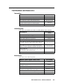
Chapter Two • Operation, Features, and Cabling .................................................... 2-1
Setup Checklist: How to Proceed With Installation............................................... 2-2
Front Panel Features and Operation............................................................................... 2-3
Buttons........................................................................................................................................ 2-3
Volume control. ......................................................................................................................... 2-4
Configuration port.................................................................................................................... 2-5
Front Panel Security Lockout (Executive Mode).................................................................... 2-6
Enabling and disabling front panel lockout via the embedded Web pages
and the front panel.............................................................................................................. 2-6
Using the Web pages (IP models).................................................................................. 2-6
Using the front panel (all models)................................................................................. 2-7
Preparing the MLC for front panel lockout........................................................................... 2-8
Setting up and enabling or disabling PINs......................................................................... 2-8
Scheduling front panel lockouts......................................................................................... 2-8
IR Control......................................................................................................................................... 2-8
IR learning. ................................................................................................................................. 2-8
IR remote control....................................................................................................................... 2-8
Panels and Cabling. ................................................................................................................... 2-9
Host/Config port cabling.......................................................................................................... 2-9
Right/rear panel and cabling................................................................................................. 2-10
Projector/display connections............................................................................................ 2-10
Additional control connections......................................................................................... 2-12
Power connection............................................................................................................... 2-20
Top panel: IR learning sensor................................................................................................. 2-20
Left side panel: reset features. .............................................................................................. 2-21
Resetting the Unit.................................................................................................................... 2-22
Pinout Guide................................................................................................................................ 2-23
MLC 104 Plus Series • Table of Contents
TOC-i
PRELIMINARY
Hardware requirements. .......................................................................................................... 1-6
Software requirements ............................................................................................................ 1-6
Table of Contents, cont’d
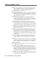
Chapter Three • Software-based Configuration and Control......................... 3-1
Configuration and Control: an Overview.................................................................... 3-2
The Basic Setup Steps: a Guide to this Chapter and Other Resources....... 3-2
Communicating with the MLC............................................................................................ 3-3
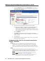
Configuring IP-enabled MLCs for Network Communication........................... 3-3
Configuring the MLC 104 IP Plus for network communication
via Global Configurator software........................................................................................... 3-4
Configuring the MLC 104 IP Plus for network communication
using the ARP command. ......................................................................................................... 3-4
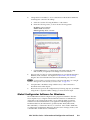
Configuring the MLC 104 IP Plus for network communication via a Web browser........ 3-5
Configuring the MLC 104 IP Plus for network communication using SIS™ commands. .. 3-6
RS-232.................................................................................................................................... 3-6
Telnet..................................................................................................................................... 3-6
Setting up the PC for IP communication with an IP-enabled MLC..................................... 3-7
PRELIMINARY
Global Configurator Software for Windows® .......................................................... 3-9
Downloading the software and getting started................................................................. 3-10
PC system requirements.......................................................................................................... 3-10
Using Global Configurator: helpful tips............................................................................... 3-10
Resources and notes........................................................................................................... 3-10
A brief guide to Global Configurator’s tabs..................................................................... 3-11
Advanced Configuration...................................................................................................... 3-12
IR learning to create customized IR driver files. ................................................................. 3-12
Advanced configuration options in Global Configurator. ................................................ 3-12
Power Settings (Display power up/power down settings)............................................... 3-12
Volume settings.................................................................................................................. 3-13
Miscellaneous settings....................................................................................................... 3-13
Configuring an auxiliary (MLS, PVS) switcher. .................................................................... 3-14
Setting up passwords for IP models...................................................................................... 3-14
Printing a wiring block diagram............................................................................................ 3-14
Updating firmware.................................................................................................................. 3-15
Saving and uploading the configuration............................................................................. 3-15
Controlling an IP Link-enabled MLC.............................................................................. 3-15
Embedded Web pages............................................................................................................ 3-15
Status................................................................................................................................... 3-16
System Status................................................................................................................ 3-16
Statistics......................................................................................................................... 3-17
Configuration..................................................................................................................... 3-17
System Settings ............................................................................................................ 3-18
Passwords...................................................................................................................... 3-18
Email Alerts................................................................................................................... 3-19
Firmware Upgrade........................................................................................................ 3-19
File Management............................................................................................................... 3-20
Control................................................................................................................................ 3-21
User Mode..................................................................................................................... 3-21
IR Drivers....................................................................................................................... 3-22
Serial Devices (serial drivers)........................................................................................ 3-22
GlobalViewer® Web Pages...................................................................................................... 3-23
TOC-ii MLC 104 Plus Series • Table of Contents
Customizing the MLC’s Control Web Pages.............................................................. 3-24
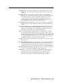
Chapter Four • SIS™ Programming and Control......................................................... 4-1
Host-to-MLC Communications............................................................................................ 4-2
MLC-initiated messages............................................................................................................ 4-2
Password information (IP models). ......................................................................................... 4-3
Error responses........................................................................................................................... 4-3
Error response references......................................................................................................... 4-3
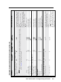
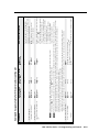
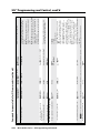
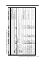
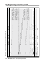
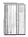
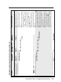
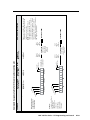
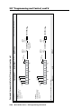
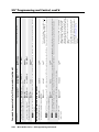
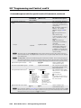
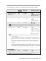
Commands and Reponses...................................................................................................... 4-4
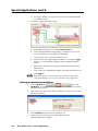
Chapter Five • Special Applications. ................................................................................... 5-1
Using Monitoring to Make Functions Track Actual Conditions. .................... 5-2
Setting up a front panel button.............................................................................................. 5-3
Setting up monitoring conditions........................................................................................... 5-4
Working With Combination Source Devices.............................................................. 5-7
Available methods..................................................................................................................... 5-7
Using an IRCM-DV+ control module and one MLC input button for DVD-VCR control.... 5-7
Scheduling Front Panel Lockout Periods.................................................................... 5-10
Sending E-mail by Pressing a Button (IP Models). ............................................... 5-11
Working With a Non-MediaLink Extron Switcher................................................. 5-14
Using Digital Inputs................................................................................................................. 5-15
Using a motorized surface access enclosure to trigger digital input............................... 5-15
Using digital input of an IP model for an alert notification system. ............................... 5-17
Using Digital Outputs............................................................................................................. 5-20
Controlling a Low Voltage Screen Motor Controller. ........................................................ 5-20
Cabling the equipment...................................................................................................... 5-20
Configuring the MLC for screen control........................................................................... 5-21
Configure the MLC’s digital I/O ports to control the IPA T RLY4’s relays.................. 5-21
Configure the MLC’s Display Power buttons to operate the digital outputs........... 5-22
Using an Amplifier and Volume Controller with the MLC.............................. 5-25
Volume control hardware setup............................................................................................ 5-25
Volume control software setup............................................................................................. 5-27
Controlling a Second Projector/Display...................................................................... 5-29
Connecting the second projector/display............................................................................. 5-29
Configuring the MLC for a second projector/display......................................................... 5-29
MLC 104 Plus Series • Table of Contents TOC-iii
PRELIMINARY
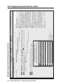
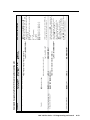
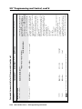
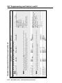
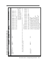
Using the command/response tables...................................................................................... 4-4
Symbol definitions..................................................................................................................... 4-5
Command/response table for SIS commands. ....................................................................... 4-8
Command/response table for special function SIS commands
(accessible via RS-232 only). ................................................................................................... 4-33
Table of Contents, cont’d
Customizing HTML Files to Control Devices, Modify Embedded Web
Pages, and Send E-mail Alerts (IP models only)......................................................5-33
Creating and using server side includes (SSIs)..................................................................... 5-33
About server side includes and the MLC........................................................................... 5-33
SSI command types and syntax.......................................................................................... 5-34
Host vs. remote commands.......................................................................................... 5-34
Command syntax.......................................................................................................... 5-34
Example: SSI use in notification e‑mails...................................................................... 5-34
SSI use in an MLC’s Web page...................................................................................... 5-35
Creating and using query strings. ......................................................................................... 5-36
Query string command types and syntax.......................................................................... 5-36
Host vs. remote commands.......................................................................................... 5-36
Command syntax.......................................................................................................... 5-36
Chapter Six • Labeling, Installation, and Mounting.............................................. 6-1
PRELIMINARY
UL/Safety Requirements......................................................................................................... 6-2
Installing or Replacing Button Labels............................................................................ 6-2
Button labeling procedure....................................................................................................... 6-2
Moving a button cap to a different button. ......................................................................... 6-3
Wiring Peripherals to the MLC. .......................................................................................... 6-3
Mounting the MLC..................................................................................................................... 6-4
Grounding to reduce electrostatic discharge........................................................................ 6-4
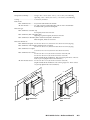
Mounting the MLC to an electrical box or mud ring........................................................... 6-6
Installing an Extron MR Series mud ring................................................................................ 6-7
Determining the installation location................................................................................. 6-7
Preparing the site and installing the mud ring using the doglegs.................................... 6-7
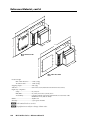
Modifying the mud ring...................................................................................................... 6-8
Mounting the MLC to a wall or furniture............................................................................ 6-10
Rack mounting an MLC 104 IP Plus L.................................................................................... 6-10
Procedure............................................................................................................................ 6-10
UL rack mounting guidelines............................................................................................. 6-11
Mounting the MLC in a Euro Channel.................................................................................. 6-11
Appendix A • Reference Material......................................................................................... A-1
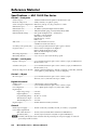
Specifications — MLC 104 IP Plus Series...................................................................... A-2
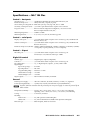
Specifications — MLC 104 Plus.......................................................................................... A-5
Part Numbers and Accessories.......................................................................................... A-7
Controllers. ................................................................................................................................ A-7
Included parts............................................................................................................................ A-7
Accessories................................................................................................................................. A-7
Glossary........................................................................................................................................... A-9
File Types: a Key to Extron-specific File Names.................................................... A-12
TOC-iv MLC 104 Plus Series • Table of Contents
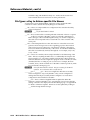
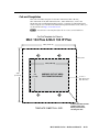
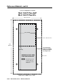
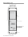
Cut-out Templates. .................................................................................................................. A-13
MLC 104 Plus and MLC 104 IP Plus....................................................................................... A-13
MLC 104 IP Plus AAP or MLC 104 IP Plus DV+..................................................................... A-14
MLC 104 IP Plus L. ................................................................................................................... A-15
MLM 104 LAAP........................................................................................................................ A-16
MLM 104 6GWP. ..................................................................................................................... A-17
Appendix B • Firmware Updates............................................................................................B-1
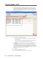
Determining the Firmware Version.................................................................................B-2
Using the Global Configurator software. ..............................................................................B-2
Using a Web browser (IP models only)...................................................................................B-2
Locating and downloading the firmware..............................................................................B-4
Updating firmware via the MLC’s embedded Web page (IP models)................................B-4
Updating firmware via Extron Firmware Loader software.................................................B-5
Updating firmware via Extron IP Link™ File Manager software (for IP models). .............B-7
Resetting the MLC and restoring its configuration..............................................................B-9
Appendix C • Index. ..........................................................................................................................C-1
Index...................................................................................................................................................C-2
All trademarks mentioned in this manual are the properties of their respective owners.
68-1443-01 Rev. B
01 09
MLC 104 Plus Series • Table of Contents TOC-v
PRELIMINARY
Updating the Main Firmware..............................................................................................B-4
PRELIMINARY
Table of Contents, cont’d
TOC-vi MLC 104 Plus Series • Table of Contents
1
Chapter One
Introduction
About This Manual
About the MLC 104 Plus Series MediaLink® Controllers
Projector Control
How the MLC 104 Plus Series Controllers Work:
MLC Components and Interactions
Optional Control Modules and IR 402 Remote Control
System Requirements
PRELIMINARY
MLC 104 Plus Series
Introduction
About This Manual
This manual provides detailed information and best practices recommendations
about cabling and configuring the Extron MLC 104 Plus Series MediaLink®
Controllers, and reference information about the controllers’ specifications,
dimensions, programming, and special applications.
It does not contain instructions on the most basic setup steps: those are covered in
the MLC 104 Plus Series Setup Guide, which describes how to set up the hardware,
how to use the Global Configurator (GC) program to download drivers, add A/V
devices to a GC configuration, configure the front panel buttons, set a shutdown
schedule, and set up e-mail alerts to flag a projector disconnection or warn that
lamp hours are exceeded.
N MLC 104 Plus requires GC version 2.50 or higher.
The IP models work with GC version 2.2 or higher
About the MLC 104 Plus Series MediaLink® Controllers
PRELIMINARY
The MLC 104 Plus Series MediaLink Controllers are capable of controlling a
projector and various other items such as lights, a projector lift, or a screen
motor. Throughout this manual they are also referred to as the MLC 104, MLC,
or “controller.” All models offer RS-232 and IR-based projector (display) control;
digital inputs and outputs for controlling items such as a projector lift, motorized
projection screen, and lights; and RS-232 remote control of an Extron switcher.
MLC 104 Plus Series features
All models can be configured and controlled via a host computer using RS‑232
communication, and the MLC 104 IP Plus models can also be configured and
controlled via IP Link™ Ethernet control. Setup and control can be accomplished by
simple ASCII commands (Simple Instruction Set, SIS™) or via the included Global
Configurator program. The software offers many more setup options than does SIS
programming.
All models offer front panel controls. The optional IR 402 remote control (which
requires an optional IR signal repeater) and optional SCP 104 Series hardwired
control pads can be used with the MLC, and they mirror the MLC’s front panel
controls. Additionally, the MLC 104 IP Plus DV+ includes an IRCM-DV+ control
module (for DVD and VCR control) installed in the faceplate.
Additional features for IP models
Via Ethernet/IP communication the MLC 104 IP Plus models can make use of
the controller’s embedded Web pages, which include online diagnostics and
monitoring of basic control features. As an integrated part of the MLC 104 IP Plus,
IP Link provides the following advantages:
Global compatibility — The MLC uses standard Ethernet communication protocols,
including ARP, DHCP, ICMP (ping), TCP/IP, Telnet, HTTP, and SMTP.
Embedded Web page serving — The MLC 104 IP Plus offers up to 7.25 MB of
flash memory for storing Extron and user-supplied Web pages, configuration
settings, and device drivers. Data in flash memory is served at a transfer rate
of 6 Mbits per second.
Multi-user support — Up to two hundred (200) simultaneous connections enable
each IP Link device to support many concurrent users and improve system
throughput by sending information in parallel.
Management ability via Global Configurator 2.2 and higher — The included
software and the GlobalViewer Web pages associated with it allow you to
control, monitor, and schedule various functions of products connected to
IP Link products such as the MLC.
1-2
MLC 104 Plus Series • Introduction
E-mail notification — The MLC 104 IP Plus can be set up to send an e-mail when
the projector has been disconnected or the projector’s lamp has been used for
a designated number of hours.
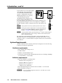
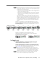
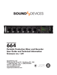
Controlling other devices
The MLC 104 Plus Series offers two methods of projector or display control:
RS-232 or infrared (IR). The MLC can learn IR signals from remote controls to
communicate with sources such as VCRs and DVD players. Users can create their
own device drivers (IR or RS-232) or go to the Extron Web site (www.extron.com) to
obtain device drivers.
TCP/IP
Network
Help Desk PC
RS-232 or
IR Projector
control
1
R
2
D
OFF
DV
3
ON
VO
LU
PC
ME
4
IG
NF
CO
4 IP
MLC
Ex
Audio
MediaLink Controller
Projector on/off control
Video
LE
EB
SS
BA
REO
IFI
MPA
PL
ER
L
LE
STE
VE
R AM
NI
WE
PO
MI
ON
LIM
ITE
R
L
DUANO
MO
OFF
Extron
MPA 122
RGBHV
Mini Power Amplifier
Extron
SI 3CT LP
DVD/VCR
Combo
tron
Extron MLC 104 IP Plus
S-Video
TR
2
12
Plus
10
Projector input switching
Audio
Projector volume control
Laptop
Full-range Ceiling
Speakers
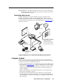
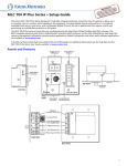
A typical application for an MLC 104 IP Plus MediaLink Controller
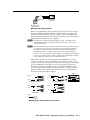
Projector Control
The MLC can control a projector or other display device by using IR or RS-232
control. The MLC must be configured for projector control in one of the following
ways before it will send commands to the projector:
• An IR or an RS-232 driver file can be installed from a disk, downloaded from the
Extron Web site (www.extron.com), or downloaded from Extron using the driver
subscription feature within Global Configurator. The driver is saved to a folder
within C:\Program Files\Extron\Driver2, and it is uploaded to the MLC via
Global Configurator.
• RS-232 command strings can be entered directly from a host computer using
Extron Global Configurator software.
• IR commands can be entered directly from an IR remote control through IR
learning and the Extron IR Learner software to create a driver that the MLC can
use. IR learning is convenient for installing new or updated commands into the
MLC in the field.
MLC 104 Plus Series • Introduction
1-3
PRELIMINARY
VC
Y
LA
SP
DI
Introduction, cont’d
Refer to the Global Configurator help file or the IR Learner help file (which
come with the software) for details on setting up the MLC and for downloading,
programming, or learning projector control commands.
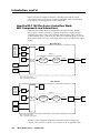
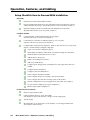
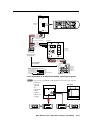
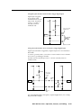
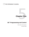
How the MLC 104 Plus Series Controllers Work:
MLC Components and Interactions
Unlike the Extron MLC 206 Series MediaLink Controllers, the MLC 104 Plus
Series requires and uses event files to perform all functions except basic input
switching and volume control. The event files define, monitor, and govern how
an MLC 104 Plus Series controller works. Below are example diagrams of how the
MLCs interact with accessories, event scripts, drivers, ports, and input and output
devices.
PRELIMINARY
MLC 104 IP Plus
PC
with
Global
Configurator
or
Web
Browser
LAN
Port
FPC*
Lights
Host
Port
FPC*
Memory
MLC 104
IP Plus
Firmware
MAIN EVENT
(0.evt)
Proj. Driver
(2.evt)
Serial
Driver
RS-232
Proj. Port
2-way
RS-232
Proj.
Serial
Driver
RS-232
Proj. Port
2-way
RS-232
Proj.
SCP*
SCP*
Lights
* FPC = front panel control
SCP = secondary control panel
MLC 104 Plus
PC
with
Global
Configurator
FPC*
Lights
Host
Port
Memory
FPC*
MLC 104
Plus
Firmware
MAIN EVENT
(0.evt)
Proj. Driver
(2.evt)
SCP*
SCP*
Lights
* FPC = front panel control
SCP = secondary control panel
The MLC can be configured completely via the Extron Global Configurator
software. Once you have set up how you want it to work (assigned drivers to
1-4
MLC 104 Plus Series • Introduction
ports, configured buttons and digital inputs or outputs, and set up IP addresses and
functions), that information is saved to a project file that is uploaded into the MLC.
The configuration information is used to create the “main event” (0.evt) script file
that defines the MLC’s operation. The main event file also controls and monitors
ports, optional SCP control panel(s), and changes made at the MLC’s front panel
(FPC, front panel control).
Each button on the MLC and on any connected SCPs has two switch numbers
assigned to it: one for the button press, one for release. Scripts are compiled to
generate the main event file to monitor any button press or release and to generate
the actions (issuing commands, triggering relays, switching inputs) associated with
the buttons.
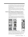
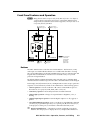
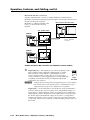
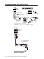
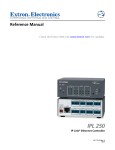
The MLC can “learn” IR commands from a VCR’s, DVD’s, tape deck’s or other
device’s remote control, allowing you to create an IR driver file that can be
incorporated into the MLC’s event scripts. A command can be associated with
each of the buttons on an optional infrared control module (such as the Extron
IRCM‑VCR, CM-5BB, CM-9BLB, or IRCM‑DV+) in order to allow limited control of
source devices.
A total of four control modules (a maximum of four control module addresses) can
be installed with this MLC. Refer to the Control Modules User’s Manual and the
IRCM‑DV+ Control Module User’s Manual for installation details and read the Global
Configurator Help file to learn about configuration. See chapter 4 of this manual for
special SIS commands for the IRCM-DV+.
VCR CONTROL
REW
PLAY
Tx
FWD
PAUSE
STOP
IRCM-VCR
CM-5BB
SCREEN POSITION
DOWN
STOP
UP
CM-3BLB
RCM-SC
CM-3BLB
DVD & VCR CONTROL
DVD
Tx
VCR
TITLE
MENU
ENTER
TV/VCR
TUNER
PREV/REW PLAY NEXT/FWD PAUSE
STOP
CM-9BLB
IRCM-DV+
CM-9BLB
AUDIO CONFERENCE
Tx
1
2
3
ON/OFF
4
5
6
HANG UP
7
8
9
FLASH
*
0
#
UNMUTE
VOLUME
CM-19AC
MUTE
CM-20BB
A few optional IRCM, RCM, and CM control modules
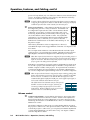
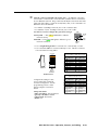
IR 402
IR remote control
The buttons on the optional IR 402 remote duplicate the MLC’s front panel controls
and also those of a VCR and a DVD player for normal operation (but not for setup).
The IR 402 can also be used to control a MediaLink Switcher. The controller or
switcher responds to commands from the IR 402 remote as if the corresponding
button or knob were pressed or turned on the controller or switcher.
MLC 104 Plus Series • Introduction
1-5
PRELIMINARY
Optional Control Modules and IR 402 Remote Control
Introduction, cont’d
From a distance of no more than 30 feet
and within 40° of the perpendicular
axis, the IR 402 sends infrared (IR)
signals to a MediaLink Controller or
MediaLink Switcher via an optional,
connected IR signal repeater.
DISPLAY
ON
OFF
VOLUME
VCR
1
DVD
2
PC
3
SIGNAL
CONFIG
4
IR Link
IR LINK
MLC 104 IP PLUS
MLC 104 IP Plus
The IR 402 remote’s Display Power
buttons, Display Mute buttons, and
the VCR and DVD control buttons will not function until they have
been programmed using GC version 2.2 or higher (2.5 or higher for
the MLC 104 Plus) and the configuration has been uploaded into the
MLC.
40°
40°
30’ (max.)
IR 402
N Setup operations cannot be performed from the remote control.
N Pressing the remote’s Display Mute On and Display Mute Off
buttons sends the 1M and 0M SIS commands (respectively) to
the MLC. See page 4‑8 to learn about these commands.
PRELIMINARY
N To increase audio volume, press the Volume up (^) button, rotate the MLC’s
Volume knob clockwise, or select a larger number in the Control tab of the
MLC’s embedded Web page.
IR commands are transmitted from the MLC’s Display RS-232/IR port (via
IR Emitter) when the corresponding button is pressed on the remote or on the
controller’s, SCP’s, or control module’s front panel. Refer to the Control Modules
User’s Manual.
System Requirements
The MLC 104 Plus Series Controllers and Global Configurator have the following
hardware and software requirements:
Hardware requirements
• Intel® Pentium® III, 1 GHz processor
• 512 MB of RAM
• 50 MB of available hard disk space
• A network connection with a minimum data transfer rate of 10 Mbps (100 Mbps
is recommended) — for IP models
Software requirements
• Microsoft® Windows® operating system
○ Windows NT service pack 4, or
○ Windows 2000 service pack 2, or
○ Windows XP service pack 2, or
○ a higher version of Windows
• Microsoft Internet Explorer® 6.0 with ActiveX® enabled — for IP models
• Microsoft Windows Script 5.6
C
1-6
Do not run Global Configurator software on a PC that uses an earlier
version of Windows.
MLC 104 Plus Series • Introduction
2
Chapter Two
Operation, Features, and Cabling
Setup Checklist: How to Proceed With Installation
Front Panel Features and Operation
IR Control
Panels and Cabling
Resetting the Unit
Pinout Guide
PRELIMINARY
MLC 104 Plus Series
Operation, Features, and Cabling
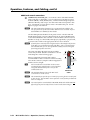
Setup Checklist: How to Proceed With Installation
Get Ready
Familiarize yourself with the MLC's features.
and install the latest version of the Extron Global Configurator software
Download
and the latest driver package. (See the MLC 104 Plus Series Setup Guide, chapter 1.)
IP setting information from the network administrator for the MLC.
Obtain
(Read the MLC 104 Plus Series Setup Guide, chapter 3.)
Configure the MLC
the MLC to the included external power supply.
Connect
(See MLC 104 Plus Series Setup Guide, chapter 2.)
the PC to the MLC via Ethernet patch or crossover cable.
Connect
(See MLC 104 Plus Series Setup Guide, chapter 2.)
PRELIMINARY
Configure MLC using Global Configurator. (Refer to MLC 104 Plus Series Setup Guide,
chapter
3, and the Global Configurator help file.)
Create a new Global Configurator project.
Set the MLC’s IP address, subnet mask, and other IP settings (for IP models).
Define the MLC’s GlobalViewer Tree location.
Add the MLC to the project.
Define e‑mail settings and contacts.
Add serial and IR drivers.
ports (Display, MLS, and Digital I/O) and assign device drivers as
Configure
needed.
Configure front panel buttons.
Configure control module buttons.
Create a display shutdown schedule.
Create a display lamp hours warning e‑mail (for IP models).
Create a display disconnection warning e‑mail (for IP models).
Perform configurations for special applications, if needed. (See chapter 5.)
Save the Global Configurator project/configuration.
Build and upload the configuration.
Perform Physical Installation
Install or replace button labels.
peripheral devices to ports on the MLC.
Cable
(See chapters 2 and 6 of this manual or chapter 2 of the setup guide.)
Test the system.
the MLC to an electrical box, wall, furniture, or rack and ground the unit.
Mount
(See chapter 6 in this manual.)
2-2
MLC 104 Plus Series • Operation, Features, and Cabling
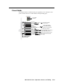
Front Panel Features and Operation
N Many features must be set up in order for the MLC to function. See chapter 3,
“Software-based Configuration and Control”, and the MLC 104 Plus Series
Setup Guide for information about Global Configurator, which you must use to
set up most features of the MLC.
1
Display power
buttons, page 2-3
2
Input selection
buttons, page 2-4
ON
OFF
VOLUME
VCR
1
DVD
2
PC
3
CONFIG
4
MLC 104 IP PLUS
MLC 104 IP Plus
Front Panel
3
Volume
control,
pg. 2-4
4
Config port,
page 2-5
N The front panels
of the IP and
non-IP models
are identical
except for the
product name.
Buttons
The MLC 104 Plus Series controllers have backlit buttons. The functions, events,
and scripts associated with these buttons are available with all models. Pressing
the corresponding button on the Extron IR 402 remote control or an Extron SCP 104
keypad will cause that button’s functions to be executed exactly as if you had
pressed a front panel button.
By default all buttons illuminate brightly when selected (active), and light dimly
when deselected. The button caps are removable so the button labels can be changed.
Each Display On/Off, Function/Room, and Input button can be set up to perform a
sequence of several functions, which can be combinations of the following options:
• a driver operation—execute an RS-232 or IR control command that is part of a
device driver (for a projector, VCR, DVD, audio source, etc.)
• a time delay operation—insert delays between executed commands
• a button light operation—change a front panel button’s brightness, color, or
flashing
• a digital input/output operation—turn the digital output on or off, toggle it, or
pulse it
• a user-defined RS-232 operation—issue a non-driver-associated RS-232 command
(one that you programmed separately) via a specific port (IR/Serial Out A, B, C;
or the projector control port) or an internal command for the MLC, itself
a
Display On/Off buttons — After they have been configured, press the On
button to turn the projector or display device on, and press the Off button to
MLC 104 Plus Series • Operation, Features, and Cabling
2-3
PRELIMINARY
DISPLAY
Operation, Features, and Cabling, cont’d
power it off. By default, only one of these two buttons can be selected (active)
at once. Via Global Configurator (GC) software, other functions and relays
can be associated with each of these buttons.
N To avoid conflicts with the front panel lockout PIN feature, Extron recommends
configuring the Display Power buttons so that the MLC sends projector/display
commands upon the button release instead of on the button press.
PRELIMINARY
b
Input selection buttons — These buttons, labeled 1 through 4, can
be configured to perform a variety of functions. Each button can
be configured for input selection and to execute the IR or RS‑232
commands of your choice, or trigger event scripts and/or port
monitoring. By default they are a mutually exclusive group: only
one of these buttons can be selected at a time. Also, by default
each button is associated with an Extron input switching Simple
Instruction Set (SIS™) command (1!, 2!, 3!, and so forth) and
bidirectional communication via the MLC’s MLS RS-232 port. See
the picture at right.
1!
2!
3!
4!
Alternatively, the buttons can be reconfigured (via software) to
select different inputs and to trigger different commands. See chapters 3 and
4 for details.
Press an input selection button to select the desired audio and video input
on the projector or an optional Extron switcher. The button for that selection
lights brighter and remains lit brighter until a different input is selected.
1
2
3
4
N When these input selection buttons are configured for input switching, there is a
default 0.5 second delay between when one input is selected and when a different
input can be selected. This allows time for the projector to adjust to the change
of sync signals. The delay period is adjustable.
If the MLC is used without an optional switcher and the MLC has been set up
for use with a projector, the selectable inputs on the MLC correspond to the
number of inputs available on the projector. If an optional Extron switcher is
connected to the MLC, all four input buttons are selectable. Which buttons
are or aren’t configured for input switching can be set via Global Configurator.
N When an input selection button is designated for input switching, pushing that
button causes the MLC to send out an SIS input change command via the MLS
RS-232 connector. In addition it can make the MLC send projector control
commands through the Display RS-232/IR port, send a digital output signal, or
send a serial command via the MLS RS‑232 port.
The default Extron SIS commands sent for each input via
the MLS connector are shown at right. If desired, you
can reassign (remap) any input from 1 to 99 to these
input buttons. Button remapping can be convenient if a
switcher is slaved to (controlled by) the MLC.
Button
Command
Input 1
Input 2
Input 3
Input 4
1!
2!
3!
4!
Volume control
2-4
c
Volume knob and LEDs — Rotate this knob clockwise to increase the audio
volume, counterclockwise to decrease volume. Volume can be adjusted via
this front panel knob, the corresponding knob on an SCP control panel, the
Volume up/down buttons on an IR 402 remote control, or via RS‑232/Telnet/
Web browser control.
The Global Configurator software lets you select whether this knob controls
the projector’s audio levels or the optional switcher’s audio levels. If the knob
controls the projector’s audio levels, you can specify incremental adjustments
or range-based adjustments (via device driver only). See chapter 3 and the
software’s help file for details.
MLC 104 Plus Series • Operation, Features, and Cabling
N Not all devices that use RS-232 for audio level control can be properly controlled
using the MLC’s Volume knob. Some devices cannot respond quickly enough to
the commands issued to them by the MLC.
• If the projector uses range adjustments, that can result in choppy audio level
ramping (volume changing in jumps).
• If the projector uses incremental adjustments (volume up/down commands),
that can result in slow audio ramping (requiring many turns of the knob to
change the volume).
If you experience problems using range-based audio control with a projector or
other device, try slowing down the MLC’s volume knob command rate by using
the 49# SIS command (see chapter 4 on SIS programming for details) or encoder
scaling in Global Configurator (see the Global Configurator Help file). If you
need further assistance, contact Extron and ask to speak with an applications
engineer.
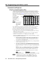
If the MLC is configured for use with a MediaLink Switcher or for some
projectors, the MLC’s LEDs indicate volume ranges (with steadily lit LEDs)
and minimum/maximum volume limits (with flashing LEDs), as shown in
the following diagram.
Range-based Volume Adjustment
VOLUME
VOLUME
VOLUME
VOLUME
Minimum,
0% of Max.
Volume
1% to 19%
of Max.
Volume
VOLUME
VOLUME
Range-based Volume Adjustment
VOLUME
20% to 39%
of Max.
Minimum,
Volume
0% of Max.
Volume
40% to 59%
of Max.
1% to 19%
Volume
of Max.
Volume
VOLUME
VOLUME
60% to 79%
of Max.
20% to 39%
Volume
of Max.
Volume
VOLUME
80% to 99%
of Max.
40% to 59%
Volume
of Max.
Volume
VOLUME
VOLUME
VOLUME
100% of
Max.
60% to 79%
Volume
of Max.
Volume
If the MLC is configured for increment/decrement volume
Increment/Decrement-based Volumeadjustment,
Adjustment the LEDs scroll up/down briefly. See the example below.
VOLUME
VOLUME
Increment/Decrement-based Volume Adjustment
VOLUME
VOLUME
Configuration port
d
Config (host control) port — This port makes it possible to upload and
configure device drivers and also to initiate IR learning via a front panel
connection after the MLC has been installed.
Connect a Windows-based PC or an RS-232 control system to this 2.5 mm
mini stereo-style (tip-ring-sleeve) connector. You can use the Extron 9-pin D
to 2.5 mm stereo mini TRS RS-232 cable (part #70-335-01) or make your own
cable. See page 2‑9 for a wiring diagram and port protocol.
N This port requires 38400 baud communication, a higher speed than many
other Extron products use. The configuration software automatically sets the
connection for the appropriate speed. If using HyperTerminal or a similar
application, make sure the PC connected to these ports is set for 38400 baud.
N Extron recommends configuring and controlling the MLC via the LAN
connector. Ethernet connections are faster and more reliable.
MLC 104 Plus Series • Operation, Features, and Cabling
PRELIMINARY
2-5
80% to 99%
of Max.
Volume
Operation, Features, and Cabling, cont’d
Front Panel Security Lockout (Executive Mode)
To prevent accidental changes to settings, the MLC features front panel security
lockout (executive) modes for disabling access to controls. When front panel
lockout is enabled, if a button is pressed, the button flashes red, but no change
occurs. Nothing—not input switching, projector control, room control, volume
adjustment, or any other knob- or button-executable function—results from front
panel actions when lockout is active. Button and knob functions on the IR 402
remote control, SCPs, or control modules are also locked. Changes can still be
made via RS-232 or, for IP models, via Ethernet (Telnet or Web browser) control.
The SIS command 3X corresponds to and also enables this mode (see page 4-10).
For details, see chapters 3 and 4. The only way to override a front panel lockout
via the front panel is to enter a personal identification number (PIN) to unlock the
panel, using the MLC’s input buttons as a numeric keypad for PIN entry, as shown
on page 2‑7.
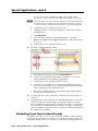
Enabling and disabling front panel lockout via the embedded Web pages
and the front panel
PRELIMINARY
Front panel lockout can be enabled/disabled using the embedded Web pages
whether or not a PIN has been set. However, a PIN must be set up before you can
enable or disable lockout using the front panel buttons.
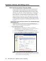
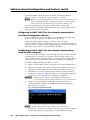
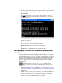
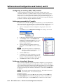
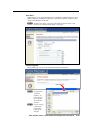
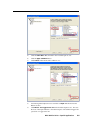
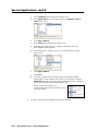
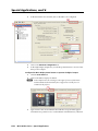
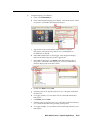
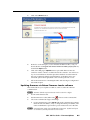
Using the Web pages (IP models)
1. Using a Web browser, enter the MLC’s IP address to open the MLC’s
embedded Web page. If an administrator password has been set and if you
are prompted to do so, type in the administrator password.
2.
Click on the Configuration tab, which opens to the System Settings page.
3.
Select either Off or Disable Front Panel, SCP, Control Modules and IR in the
Executive Mode settings area. See the following picture.
N If Disable Front Panel, SCP, Control Modules and IR is selected via the
System Settings factory default Web page, front panel lockout can’t be enabled/
disabled via the front panel unless PIN Mode is enabled. See page 4-40 to find
the SIS commands for PIN enabling/disabling.
2-6
MLC 104 Plus Series • Operation, Features, and Cabling
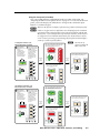
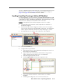
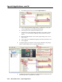
Using the front panel (all models)
One or more PINs must be configured before this procedure can be used. See
“Preparing the MLC for front panel lockout” on page 2-8. To lock/unlock the front
panel, you use the Display On/Off buttons to change modes and use the input
buttons as a numeric keypad.
N Make sure the projector or display is off before using a PIN to lock the front panel.
N Failure to configure the On or Off buttons to send display/projector commands
upon button release (instead of button press) may cause problems with the PIN
Mode feature. (If one On/Off button is pressed before the other, and the buttons
are configured to send commands at the button press, the first button’s actions
can be executed, preventing you from locking the front panel until the display’s
warm-up or cooldown period finishes.)
1 Press and hold
both Display On/Off
buttons
simultaneously.
The Display On/Off
buttons light green,
the other buttons
dim, and the bottom
Volume LED blinks.
1
If the correct PIN is entered, the green Volume
LEDs flash and all buttons flash red 3 times,
indicating that front panel is locked.
2 While still pressing the
Display buttons, enter
the PIN. Use the
input selection buttons
as a 4-key numeric
keypad; press one
button at a time.
One green Volume
LED lights at a time
as the buttons are
pressed.
DISPLAY
ON
1
OFF
2
VOLUME
1
2
DISPLAY
ON
OFF
VOLUME
1
1
2
2
N The PIN can be
entered via either the
MLC or the SCP.
Then the buttons light as they were lit
before front panel lockout was set.
3
3
4
4
DISPLAY
Release
all
buttons.
CONFIG
Release
all
buttons.
ON
1
OFF
2a
2c
2
VOLUME
If an incorrect PIN is entered, no buttons
flash, the green Volume LEDs turn off,
and the red (top) LED blinks.
3
DISPLAY
CONFIG
3
3
2d
4
4
2b
ON
OFF
VOLUME
This example shows the
default administrator PIN:
1 2a , 4 2b , 2 2c , 3 2d .
CONFIG
Unocking the Front Panel of an
MLC 104 Plus Series Controller
1 Press and hold
both Display On/Off
buttons
simultaneously.
The Display On/Off
buttons light red,
the other buttons
dim, and the bottom
Volume LED blinks.
1
2 While still pressing the
Display buttons, enter
the PIN. Use the
input selection buttons
as a 4-key numeric
keypad; press one
button at a time.
One green Volume
LED lights at a time
as the buttons are
pressed.
1
OFF
2
VOLUME
1
2
2
3
3
4
4
4
If the correct PIN is entered, the green Volume
LEDs flash and all buttons flash green 3
times, indicating that front panel is locked.
DISPLAY
ON
CONFIG
1
1
2
DISPLAY
ON
OFF
VOLUME
1
1
2
2
Then the buttons light as they were lit
before front panel lockout was set.
3
3
4
4
DISPLAY
Release
all
buttons.
CONFIG
Release
all
buttons.
ON
1
OFF
2a
2c
If an incorrect PIN is entered, no buttons
flash, the green Volume LEDs turn off,
and the red (top) LED blinks.
2
VOLUME
3
DISPLAY
CONFIG
3
3
2d
4
4
2b
ON
OFF
VOLUME
This example shows the
default administrator PIN:
1 2a , 4 2b , 2 2c , 3 2d .
CONFIG
CONFIG
1
1
2
2
3
3
4
4
MLC 104 Plus Series • Operation, Features, and Cabling
4
2-7
PRELIMINARY
Locking the Front Panel of an
MLC 104 Plus Series Controller
Operation, Features, and Cabling, cont’d
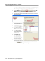
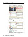
Preparing the MLC for front panel lockout
To allow access to front panel changes to specific personnel while the front panel is
locked, you can set a user and/or administrator PIN and set which type of PIN, if
any, is allowed to unlock the panel.
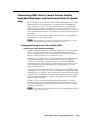
Setting up and enabling or disabling PINs
Using the Advanced Configuration tab within Extron Global Configurator (GC)
software, you can configure which PIN to enable (which PIN will be allowed to
unlock the front panel), or disable both PINs so that no one can access the front panel
during front panel lockout. And you can set the fourdigit PINs for the administrator and for users.
N Each digit of the PIN must be a number
from 1 to 4 because they represent the MLC’s
four input buttons, which will be used as a
numeric keypad. By default, both PINs are set
to 1423. Refer to the Global Configurator
Help file for the PIN setup procedure.
PRELIMINARY
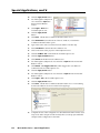
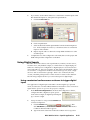
Scheduling front panel lockouts
You can set the MLC’s front panel to be automatically locked at certain times and days by setting up a schedule using the Schedule tab
within the Global Configurator software and uploading it to the MLC. The Global
Configurator Help file includes instructions on how to set up a scheduled action.
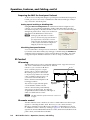
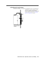
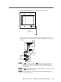
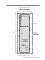
IR Control
IR learning
The IR learning receiver sensor on the MLC 104 Plus Series’ top panel can receive
IR Learning
and “learn” commands from other devices’ infrared
Receiver
remotes so you can create an IR driver
file to control the projector or input
devices such as a VCR or DVD player.
IR learning of projector control codes
is only necessary if there are no RS-232
IR
codes available for that projector or if
you need to customize the driver.
Refer to the IR Learner help file for IR
learning procedures.
MLC 104 IP Plus
Top Panel
This receiver accepts infrared signals
of from 30 kHz to 62 kHz. The IR
remote control must be pointed directly
at the receiver for best results. The diagram
at right indicates the best distances and angles at
which to hold the remote control.
N The MLC 104 Plus requires IR Learner version 1.23
or higher.
2"–12"
(4–30 cm)
1
2
3
4
5
6
7
8
9
0
IR remote control
The MLC 104 Plus Series controllers do not have a built-in IR receiver that accepts
signals for controlling the MLC, itself. However, you can connect an Extron
IR Link or an IR Sensor remote IR receiver to the MLC’s CommLink port as shown
in “Additional control connections,” starting on page 2-12. Those devices can receive
signals from an Extron IR 402 infrared remote control, which mirrors the MLC’s front
panel controls, and sends them to the MLC.
2-8
MLC 104 Plus Series • Operation, Features, and Cabling
Panels and Cabling
Host/Config port cabling
DISPLAY
ON
OFF
VCR
1
DVD
2
PC
3
VOLUME
CONFIG
MLC 104 IP PLUS
MLC 104 Plus Series
Front Panel
1
a
Front panel Config (host control) port — For MLC configuration and control,
connect a Windows®-based PC or an RS-232 control system to the MLC via
this 2.5 mm mini stereo jack. This port is accessible even after the MLC has
been installed and cabled. The optional
9-pinTRS
D to
2.5 mm stereo mini TRS
9DBF-2.5mm
cable_031504.eps
RS‑232 cable (part #70‑335‑01, shown below) can be used for this connection.
RS-232 protocol:
• 38400 baud
• 1 stop bit
• no parity
• 8 data bits
• no flow control
6 feet
(1.8 m)
1
Part #70-335-01
6
9
5
Tip
Ring
Sleeve (Gnd)
9-pin D
Connection
TRS Plug
Pin 2
Pin 3
Pin 5
Computer's RX line
Computer's TX line
Computer's signal ground
Tip
Ring
Sleeve
N This configuration port requires 38400 baud communication. This is a higher
speed than many other Extron products use. Global Configurator software
may automatically set the connection for the appropriate speed. If using
HyperTerminal or a similar application, make sure the PC or control system
connected to these ports is set for 38400 baud.
N For the IP models, Extron recommends configuring and controlling the MLC via
the LAN connector on the right side panel. Ethernet connections are faster and
more reliable.
MLC 104 Plus Series • Operation, Features, and Cabling
2-9
PRELIMINARY
4
Operation, Features, and Cabling, cont’d
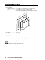
Right/rear panel and cabling
MLC 104 IP Plus
Right Side Panel
6
Rear Panel
(IP models
only)
Tx
DISPLAY A B C D E
RS-232/IR
COMM LINK
1
Rx
RUN
100
1
GROUND
IR OUT
+V OUT
GROUND
2
2
CM
IR IN
LAN
SCP
DIGITAL
I/O
PRESS TAB WITH
TWEEKER TO REMOVE
1
3
2
3
GROUND
PRELIMINARY
Rx
B
MLS
PWR
RS-232 12V
5
A
4
Tx
GROUND
3
4
GROUND
5
+12V IN
a
b
c
Display control (Display RS-232/IR) port (page 2-10)
d
e
f
MLS connector (page 2-17)
CM/IR/SCP (CommLink) port (page 2-12)
Digital I/O ports (24 V, 1 A) (page 2-14 and “Using Digital Inputs” and
“Using Digital Outputs” in chapter 5)
PWR (power) connector (page 2-20)
LAN (IP) connector and LEDs (page 2-19) — IP models only
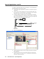
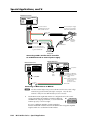
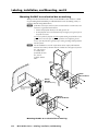
Projector/display connections
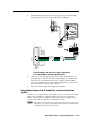
a
Display control (Display RS-232/IR) port (-5 VDC to +5 VDC) —
From this port, commands from a projector driver or user-defined command
strings entered via Global Configurator can be sent to the display device.
Connect a cable between the projector or display and the left three poles
(TX, RX, Ground) of this 3.5 mm direct insertion captive screw connector for
bidirectional RS‑232 control. The IR Out and Ground pins (the right two
poles) can be used for one-way infrared signal output to control the display/
projector or some other device, such as a VCR or DVD player. Use the
following illustrations as a wiring guide.
Transmit (Tx)
Receive (Rx)
Ground ( )
Bidirectional RS-232
Transmit (Tx)
Receive (Rx)
Ground ( )
Projector/
Panel Display
NOTE
The connector accepts one wire
per pole. You may need to
splice projector and IR Emitter
ground wires to a single wire
that is inserted into this port.
IR Emitter
Ground (
IR Signal
Strip
wires
3/16”
(5 mm)
max.
)
To a Source’s
IR Receiver
Rx
IR OUT
Tx
GROUND
Unidirectional IR Output
via White Striped Wire
100'
(30.5 m)
DISPLAY
RS-232/IR
MLC 104 Plus Series
Right Side Panel
Wiring for RS-232 display control and IR source device control
2-10
MLC 104 Plus Series • Operation, Features, and Cabling
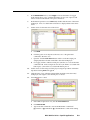
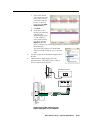
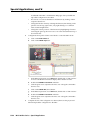
Ground ( )
IR Control
Ground ( )
IR Output
Unidirectional IR
Rx
IR OUT
Tx
GROUND
Strip wires
3/16” (5 mm) max.
Projector,
Panel Display,
or Source Device
DISPLAY
RS-232/IR
MLC 104 Plus Series
Right Side Panel
Wiring for IR display control
Wiring varies depending on the projector/display model. In most cases the
drivers are bidirectional, but sometimes only the transmit (Tx) and ground
connections will be needed for projector/display control. For bidirectional
RS-232 communication, the transmit, ground, and receive pins must be wired
at both the MLC and the projector or display.
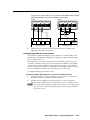
N Maximum distances between the MLC and the device being controlled may vary
up to 200 feet (61 m). Factors such as cable gauge, baud rates, environment,
and output levels (from the MLC and the device being controlled) all affect
transmission distance. Distances of about 50 feet (15 m) are typically not a
problem. In some cases the MLC may be capable of transmitting and controlling
a given device via RS-232 up to 250 feet (76 m) away, but the RS-232 response
levels of that device may be too low for the MLC to detect.
Alternatively, an MLC can use infrared signals and IR Emitters to control
several source devices. However, the MLC’s direct insertion captive screw
connectors have small openings that accept just one wire per pole. To connect
up to two IR Emitters to the MLC, insert one ground and one signal wire
in the MLC’s Display RS‑232/IR port, then connect the IR Emitters to those
wires. If using all single emitters or all double emitters, wire the emitters in
parallel. If using a mix of both single and dual emitters, see the IR Emitter
Installation Guide, part number 68-808-01.
VCR
IR Signal
Ground
(+)
(-)
(+)
Ground
IR Signal
(-)
(-)
(+)
(+)
(+)
(-)
(-)
Single and Dual IR Emitter
Two Single IR Emitters
DVD Player
(-)
(-)
Ground
IR Signal
(-)
IR Signal
(+)
(+)
(+)
(-)
Ground
(+)
(+)
(+)
(-)
(-)
(+)
(-)
Dual IR Emitters
Two Single & 0ne Dual IR Emitter
Legend
(–)
(+)
Black wire
Black wire
w/white stripe
Wiring for IR control of up to two sources
MLC 104 Plus Series • Operation, Features, and Cabling
2-11
PRELIMINARY
N Each projector or display may require different wiring. For details, refer to
the manual that came with the projector/display or the Extron device driver
communication sheet.
Operation, Features, and Cabling, cont’d
Additional control connections
b
CM/IR/SCP (CommLink) port — For remote control of the MLC 104 Plus
Series controller or other items, you can connect up to four Extron control
modules (IRCMs, ACMs, RCMs, CMs), one Extron infrared signal repeater
(IRL 20 or IR Link), and/or up to two Extron SCP 104 control panels to this
port. A maximum of seven devices can be connected to this port. See the
figures on pages 2‑13 and 2‑14.
N The SCP 104 must have firmware 1.01 or greater and DIP switch 4 in the
On (up) position to operate with an MLC 104 Plus Series controller. Refer to
the SCP 104 User’s Manual for more details.
The SCP 104 replicates the MLC’s front panel controls. The SCP 104 and
the IR signal repeater can receive IR signals from an optional IR 402 remote
control and send them to the controller. Control modules can be used (once
the MLC is set up) to control VCRs, DVD players, tape decks, a projector lift,
or screen control. Refer to the appropriate device’s user’s manual.
PRELIMINARY
N If outside factors such as fluorescent light interfere with and affect the function
of the MLC, you can disable IR control of the MLC. Using a special function
SIS command (65#), you can turn off the MLC’s ability to receive IR signals
from IR signal repeaters and SCPs.
The control modules, IR signal repeater, and SCPs
can be daisy chained. Wire the connections as shown
in the diagrams on the following pages.
Extron Comm-Link (CTL and CTLP) cable is
recommended for these connections. Before inserting
wires in the connectors, strip the cable and apply heat
shrink as shown at right.
T
For best results and to avoid short circuits, Extron
recommends using shielded wires or wires insulated
using heat shrink (instead of bare wires) for the
common/drain wires.
N The maximum distance between the MLC and a
connected device is 200’ (61 m).
3/16”
(5 mm) Max.
7/8”
(22 mm)
Heat Shrink on
Outer Jacket to
Inner Conductor
Transition
Extron
Comm-Link
Cable
N The CommLink port provides up to 12 VDC for powering the SCP control panel
or other devices. The automatic current protection circuit for this port limits the
draw to 0.5 amperes.
N SCP control panel or control modules (CM, IRCM, RCM) used with the MLC are
affected by front panel security lockout (executive mode) status changes.
2-12
MLC 104 Plus Series • Operation, Features, and Cabling
IR Link
Maximum =
1 IR Link
SIGNAL
IR 402
IR LINK
A +12 VDC
B Ground
and Drain
D Modulated IR
(from IR Link)
SCP 104
Heat Shrink over Drain Wire
+12 VDC
Ground ( )
IRCM, ACM, RCM
DISPLAY
ON
VCR
1
DVD
2
PC
3
Maximum =
2 SCPs
Per System
1
CM
SCP
IR IN
+V OUT
VOLUME
GROUND
OFF
SCP communication (IR)
A B C D E
COMM LINK
PRELIMINARY
A
B
C
D
E
4
MLC 104 Plus Series
Right Side Panel
SCP 104
C IRCM/ACM/RCM
B Ground ( )
A +12 VDC
200' (61 m) Max.
to Last Device
DVD & VCR CONTROL
DVD
Tx
VCR
TITLE
MENU
ENTER
TV/VCR
Maximum =
4 Control
Modules
(4 module
addresses)
TUNER
Extron CTLP Cable Color Code:
E
D
C
B
A
SCP Communication
Modulated IR (for IR Link)
Control Module Communication
Ground ( ) & Drain Wire
+12 VDC
= White
= Gray
= Violet
= Black and Drain Wire
= Red
PREV/REW PLAY NEXT/FWD PAUSE
STOP
IRCM-DV+
Basic connections to an SCP, control module, and IR signal repeater
1 2 3 4
ON
N If you connect a CM-3BLB or CM‑9BLB to an SCP 226’s 3-pole connector
instead of to
MLC 104 Plus Series
SCP 104 Rear Panel
its 5-pole
Rear Panel
connector,
the
CM‑xBLB
control
module’s
buttons will
not light.
RUN
100
J1
A B C D E
A B C D E
A B C D E
A B C D E
CM-3BLB
CM-3BLB Front
CM-3BLB
CM-3BLB Rear
CM-3BLB Rear
CM-3BLB Front
MLC 104 Plus Series • Operation, Features, and Cabling
2-13
Operation, Features, and Cabling, cont’d
MLC 104 IP Plus DV+ connections:
The MLC 104 IP Plus DV+ consists of an MLC 104 IP Plus controller and an
IRCM‑DV+ installed in a high-impact plastic faceplate. The wiring is the same as in
the previous diagram, except the
MLC 104 IP Plus DV+ Rear Panel
IRCM‑DV+ is cabled to the MLC at the
factory, as shown in the following
diagram.
RUN
100
SCP 104 Rear Panel
A B C D E
A B C D E
1 2 3 4
A B C D E
Factory-wired
MLC - to - IRCM-DV+
Connection
ON
PRELIMINARY
J1
IRCM-DV+
Rear Panel
A B C D E
1 2 3 4
A B C D E
ON
IRCM-DV+
Rear Panel
A B C D E
J1
SCP 104 Rear Panel
An MLC 104 IP Plus DV+ with SCPs and additional control modules
C
2-14
3
GROUND
1
Digital I/O ports — The Digital I/O area (shown at right) provides
three ports that can be configured as digital inputs or outputs,
with or without +5 VDC pull-up. Connecting these ports to
DIGITAL
sensors, switches, LEDs, or relays allows for a way to trigger
I/O
events or functions (such as triggering relays, issuing commands,
Right
or sending an e-mail) that have been configured using Global
Side Panel
Configurator (GC) software.
2
c
Configure these ports using Global Configurator software or SIS commands
first, and then connect wires the MLC’s ports. A mismatch between port
configuration and wiring can cause malfunctions or unit failure.
Digital input — To allow the MLC to monitor devices such as push buttons,
connect a switch, motion sensor, moisture sensor, tally feedback output, or a
similar item to a digital input port. When one of these ports is configured as
a digital input, it is set to measure two states: high and low. The port accepts
0 to 12 VDC input. The threshold voltages are as follows: a voltage below
2.0 VDC is measured as logic low, and a voltage above 2.8 VDC is measured
as logic high. There is also an internal, +5 VDC, selectable, pull-up resistor for
this circuit.
MLC 104 Plus Series • Operation, Features, and Cabling
MLC104 DigInput-02
Using these pins and an external switch to trigger digital input
Digital input is triggered
by an external switch
wired between the I/O pin
and ground. The pull-up
resistor to +5.0 VDC is
activated (switch 2 is
enabled/closed).
MLC 104 IP Plus
+12 V
+5.0 V
2k ohms
Pin 1, 2, or 3 of the
Digital I/O Port
SW 2
Digital
Input
CTL
Normally
Open
Switch
Digital I/O Port GND
MLC104 DigInput-04
Using a motorized surface access enclosure to trigger digital input
Digital input at the MLC is triggered by a digital output from a motorized Extron
HSA 822M.
A closure to ground (switch 1) occurs when a certain condition is met on the HSA.
This closure to ground triggers the MLC.
The MLC must have the pull-up resistor to +5.0 VDC activated (switch 2 is
enabled/closed).
MLC 104 IP Plus
+12 V
HSA 822M/MS
+12 V
+5.0 V
2k ohms
SW 2
Pin 1, 2, or 3
of the Digital
I/O Port
Digital
Input
Status
Pin
CTL
CTL
SW 1
GND
GND
Digital I/O Port
GND
See “Using Digital Inputs” in chapter 5, “Special Applications”, for a wiring
diagram for this example.
MLC 104 Plus Series • Operation, Features, and Cabling
2-15
PRELIMINARY
GND
Operation, Features, and Cabling, cont’d
Digital output — To power LEDs, incandescent lights, or other devices that
accept a TTL signal, or to provide contact closure control for projector lifts,
motorized screens, room or light switches via an Extron IPA T RLY4, you can
use one or more of these ports as a digital output. Each I/O port is capable of
MLC104 DigOutput-01
accepting 250 mA, maximum.
If the application calls for TTL compatibility,
the digital output circuit can be set up to provide a 2k ohm pull-up resistor to
+5 VDC.
When a digital I/O pin is configured
as a digital output, it is set to offer
two output states: “on” and “off”.
MLC 104 Plus Series
+12 V
When the port is set to an “on” state,
switch 1 (SW 1) closes and the I/O
pin connects to ground.
+5.0 V
2k ohms
When the port is set to the “off” state,
switch 1 opens and the I/O pin floats.
PRELIMINARY
The MLC 104 Plus Series controller
cannot provide TTL level outputs
like some of the IP Link interfaces.
Switch 2 cannot be enabled when
I/O pin is used as an output.
Pin 1,
2, or 3
of the
Digital
I/O Port
SW 2
I/O
CTL
SW 1
When used as a digital output, a
digital output pin on the MLC may
GND
not work with certain devices
requiring contact closure control.
Digital
I/O
Although the illustration shows a
Port
short to ground when switch 1 is
GND
enabled, the actual circuit does not
provide a completely grounded
output.
For any devices requiring contact closure
MLC104
DigOutput-02
control, it is recommended that relays be used.
The digital
output pin
drives an LED
using an
external
+5 VDC source.
MLC 104 Plus Series
+12 V
390
Ohms
The LED lights
only when the
I/O pin is set
to “on”
(switch 1 is
closed).
LED
+5 V
+
External
Source
Digital
Output
CTL
SW 1
GND
N The I/O pin is capable of sinking a maximum of 250 mA from 12 VDC, max.
2-16
MLC 104 Plus Series • Operation, Features, and Cabling
MLC104 DigOutput-03
The digital
output pin
drives an LED
using the
+12 VDC
output of the
controller as a
voltage source.
The LED lights
only when the
I/O pin is set
to “on”
(switch 1 is
closed).
MLC 104 Plus Series
+12 V
+12 V
2k
Ohms
LED
Pin 1, 2,
or 3
Digital
Output
CTL
SW 1
GND
N The I/O pin is capable of sinking a maximum of 250 mA from 12 VDC, max.
The digital
output pin
drives an
incandescent
lamp using the
+12 VDC
output of the
controller as
the voltage
source.
The lamp lights
only when the
I/O pin is set
to “on”
(switch 1 is
closed).
d
MLC 104 Plus Series
+12 V
+12 V
+12 V Out
Lamp
Digital
Output
CTL
SW 1
GND
N The I/O pin is capable of sinking a maximum of 250 mA from 12 VDC, max.
MLS connector — To control an optional Extron switcher or other RS‑232
controllable device, connect a cable between this 3.5 mm direct insertion
captive screw connector and the RS‑232 port of the other device. By default
this port supports any Extron switcher without additional drivers. If it is used
to control other products, additional device drivers may be required.
N The commands issued from this port are standard Extron SIS commands, and
they follow the typical Extron RS‑232 protocol:
• 9600 baud
• 8 data bits
• 1 stop bit
• no parity
If you connect an optional switcher (such as an Extron MLS Series or PVS
Series switcher) to the MLC, you must connect a ground wire between the
switcher and the MLC, as shown in the following diagrams.
MLC 104 Plus Series • Operation, Features, and Cabling
2-17
PRELIMINARY
MLC104 DigOutput-04
Connecting an
MLC 104 Plus Series controller
to an external power supply
Ground all devices.
Operation, Features, and Cabling, cont’d
50-60Hz
INPUTS
1
R
OUTPUTS
G
B
H
V
VIDEO
AUDIO INPUTS
AUX/MIX
INPUTS
2
1.0A MAX.
3
AUDIO
4
AUDIO
LINE LEVEL
MONO
ADJUST
-42dB
TO
+24dB
L
1
L
12V
AMPLIFIED OUTPUT
RIGHT
LEFT
A B C
LINEOUT
L
R
RS-232/MLC/IR
PREAMP
L
R
4/8 ohm
STEREO OR DUAL MONO
A B C D E
COMM LINK
DIGITAL
I/O
Tx
+12V IN
B
GROUND
A
GROUND
1
3
2
PRESS TAB WITH
TWEEKER TO REMOVE
Rx
SCP
IR IN
Rx
CM
GROUND
Tx
IR OUT
DISPLAY
RS-232/IR
+V OUT
GROUND
LAN
MLS 304SA Rear Panel
Strip wires 3/16” (5 mm) max.
NOTE
Tx Rx IR
2
R
R
MONITOR OUT
CLASS 2 WIRING
100-240V
MediaLink
Switcher's
rear panel
MLC/IR port
GROUND
MLC/IR
ABC
PWR
MLS
RS-232 12V
MLC 104 IP Plus
Right Side Panel
You must connect a
ground wire between
the MLC and MLS.
External
Power Supply
Ground ( )
Ground ( )
+12 VDC input
MLC's
MLS and
Power
ports
+12V IN
Tx
B
GROUND
A
GROUND
NOTE If you use cable that
has a drain wire, tie
the drain wire to
ground at both ends.
Rx
Transmit (Tx) B
Receive (Rx) A
B Receive (Rx)
A Transmit (Tx)
MLS
PWR
RS-232 12V
External
Power Supply
(12 VDC)
Ground all devices.
PRELIMINARY
Connecting an MLC 104 Plus Series
to a MediaLink Switcher and an external power supply
RS-232/MLC/IR
Tx Rx IR
+12V
A B C D E
PVS 204SA
Switcher's rear panel
RS-232/MLC/IR port
Heat Shrink
over Shield
NOTE
+12 VDC
Ground ( )
Ground ( )
B Receive (Rx)
A Transmit (Tx)
If you use cable that has a drain
wire, tie the drain wire to
ground at both ends.
Transmit (Tx) B
Receive (Rx) A
+12V IN
B
GROUND
Tx
A
GROUND
Rx
Heat Shrink
over Shield
MLS
PWR
RS-232 12V
MLC's MLS and
Power ports
2-18
Connecting an MLC 104 Plus Series
controller to a PVS Switcher
MLC 104 Plus Series • Operation, Features, and Cabling
f
LAN (IP) connector and LEDs (IP models only) — An Ethernet connection
can be used to connect and to control the MLC (and the devices connected to
it) in an Ethernet network. Plug a cable into this RJ-45 socket and connect the
other end of the cable to a network switch, hub, router, or PC connected to an
Ethernet LAN or the Internet.
• For 10Base-T (10 Mbps) networks, use a CAT 3 or better cable.
• For 100 Base-T (max. 155 Mbps) networks, use a CAT 5 cable.
You will also need to configure this port before using it.
LAN
RJ-45
Port
Activity LED — This yellow LED blinks to indicate
network activity.
Link LED — This green LED lights to indicate a good
network connection.
Link
LED
Activity
LED
• Use a straight-through cable for connection to a switch, hub, or router.
Pins:
12345678
Straight-through Cable
(for connection to a switch, hub, or router)
End 1
Side View
Insert
Twisted
Pair Wires
Pin
1
2
3
4
5
6
7
8
RJ-45 Connector
Wire Color
white-orange
orange
white-green
blue
white-blue
green
white-brown
brown
End 2
Pin
1
2
3
4
5
6
7
8
Wire Color
white-orange
orange
white-green
blue
white-blue
green
white-brown
brown
Crossover Cable
(for direct connection to a PC)
Configure the settings for this
port via either SIS commands
or Global Configurator. See the
programming sections of this
manual (chapters 3 and 4) for
details.
LAN port defaults:
• MLC’s IP address: 192.168.254.254
• gateway’s IP address: 0.0.0.0
• subnet mask: 255.255.0.0
• DHCP: off
End 1
Pin
1
2
3
4
5
6
7
8
Wire Color
white-orange
orange
white-green
blue
white-blue
green
white-brown
brown
End 2
Pin
1
2
3
4
5
6
7
8
Wire Color
white-green
green
white-orange
blue
white-blue
orange
white-brown
brown
MLC 104 Plus Series • Operation, Features, and Cabling
2-19
PRELIMINARY
• Use a crossover cable for connection directly to a PC. Wire the connector
as shown in the following tables.
Operation, Features, and Cabling, cont’d
Power connection
e
PWR (power) connector — To provide power to the MLC, connect a cable
between this port and a 12 VDC, 2 amp (maximum) power supply. See the
following diagram.
N Power the controller via an external power supply, not from an Extron switcher.
The controller requires a separate 12 VDC power supply.
PRELIMINARY
N Check the power supply’s
polarity before
connecting it
to the MLC.
A
See the
MLC/IR
illustration
MediaLinkat
ABC
right.Switcher's
rear panel
MLC/IR port
Ground all devices.
End View of Power
Supply Output Cord
A
100-240V
50-60Hz
INPUTS
1
R
OUTPUTS
G
B
H
V
AUDIO
MONITOR OUT
LINE LEVEL
MONO
AUDIO
4
VIDEO
AUDIO INPUTS
AUX/MIX
INPUTS
3
2
1.0A MAX.
3/16”
(5 mm)
MAX.
ADJUST
-42dB
TO
+24dB
L
1
L
Tx Rx IR
2
12V
AMPLIFIED OUTPUT
RIGHT
LEFT
A B C
LINEOUT
L
R
RS-232/MLC/IR
PREAMP
L
R
SECTION A–A
R
R
4/8 ohm
STEREO OR DUAL MONO
+12V IN
Connecting an
MLC 104 Plus Series controller
to an external power supply
CLASS 2 WIRING
MLS
PWR
RS-232 12V
External
Power Supply
(12 VDC)
MLC's
MLS and
Power
ports
GROUND
+12V IN
Tx
B
GROUND
A
GROUND
Rx
Ground ( )
+12 VDC input
MLC's
Power
Port
PWR
MLSOutput
304SACord
Rear Panel
Power Supply
12V
LAN
Top panel: IR learning sensor
PRESS TAB WITH
TWEEKER TO REMOVE
DIGITAL
I/O
Rx
Tx
+12V IN
B
GROUND
A
GROUND
1
3
2
GROUND
CM
SCP
Rx
Tx
IR IN
A B C D E
COMM LINK
PWR
MLS
RS-232 12V
ground wire between
the MLC and MLS.
)
Ground ( )
+12 VDC input
B
+12V IN
A
GROUND
NOTE If you use cable that
has a drainIR wire, tie
the drain wire to
ground at both ends.
Tx
Transmit (Tx) B
Receive (Rx) A
Rx
B Receive (Rx)
A Transmit (Tx)
GROUND
MLC 104 Plus Series
Ground (
Top Panel
+V OUT
IR OUT
DISPLAY
RS-232/IR
GROUND
GROUND
In most cases, Extron has already produced an IR driver file for controlling the
Strip wires
3/16”
(5 mm)to
max.
projector or display
you
plan
use. If a device driver file is not available,External
you can
MLC
104 projector
IP Plus
Power Supply
create your own using Extron IR Learner software,
the
or display’s
remote
Right Side Panel
NOTE IR
You
must connect
a sensor,
control, and the MLC’s
learning
receiver
shown below.
MLS
PWR
RS-232 12V
IR
MLC's
MLS and
Power
ports
External
Power Supply
(12 VDC)
2–12"
(4–30 cm)
Ground all devices.
Connecting an MLC 104 Plus Series
IR Learning
to a MediaLink
Switcher and an external power supply
Receiver
1
2
3
4
5
6
7
8
9
0
Refer to the IR Learner Help File for instructions on how to create the driver file.
During the IR command capturing process, hold the projector’s remote between 2"
and 12" from and pointed directly at the MLC’s IR learning sensor, as shown above.
N The MLC 104 Plus requires IR Learner version 1.23 or higher.
2-20
MLC 104 Plus Series • Operation, Features, and Cabling
Left side panel: reset features
Reset button and LED — Pressing this recessed button causes various IP functions
and Ethernet connection settings to be reset
to the factory defaults. The green LED
flashes in a predetermined pattern depending
on the selected reset mode. See “Resetting
the Unit” on page 2‑22 for details.
Reset
LED
R
PRELIMINARY
Reset
button
MLC 104 Plus Series
Left Side
MLC 104 Plus Series • Operation, Features, and Cabling
2-21
Operation, Features, and Cabling, cont’d
Resetting the Unit
There are four reset modes (numbered 1, 3, 4, and 5 for the sake of comparison
with an Extron IPL product) that are available by pressing the Reset button on the
side panel. The Reset button is recessed, so use a pointed stylus, ballpoint pen, or
Extron Tweeker to access it. See the following table for a summary of the modes.
C
Review the reset modes carefully. Using the wrong reset mode may result
in unintended loss of flash memory programming, port reassignment, or a
controller reboot.
N The reset modes listed below close all open IP and Telnet connections and close
all sockets. The following modes are separate functions, not a continuation from
Mode 1 to Mode 5. Also, IP settings do not apply to the MLC 104 Plus.
Reset Mode Comparison/Summary
Mode Activation
1
Hold down the recessed
Reset button while applying
power to the MLC.
PRELIMINARY
After a mode 1 reset
is performed, update the
MLC’s firmware to the latest
version. Do not operate the
MLC firmware version that
results from the mode 1
reset. If you want to use the
factory default firmware, you
must upload that version
again. See appendix B,
“Firmware Updates,” for
details on uploading
firmware.
2-22
Result
Purpose/Notes
The MLC reverts to the factory default
firmware. Event scripting will not start if
the MLC is powered on in this mode. All
user files and settings (drivers,
adjustments, IP settings, etc.) are
maintained.
Use mode 1 to revert
to the factory default
firmware version if
incompatibility issues
arise with
user-loaded firmware.
If you do not want to update
firmware, or you performed a mode 1 reset
by mistake, cycle power to the MLC to
return to the firmware version that was
running prior to the mode 1 reset. Use the
0Q SIS command to confirm that the
factory default firmware is no longer
running (look for asterisks following the
version number.)
3
Hold down the Reset button
for about 3 sec. until the Reset
LED blinks once, then release
and press Reset momentarily
(<1 sec.) within 1 second.
Mode 3 turns events on or off. During
resetting, the Reset LED flashes 2 times if
events are starting, 3 times if events are
stopping.
Mode 3 is useful for
troubleshooting.
4
Hold down the Reset button
for about 6 sec. until the
Reset LED has blinked twice
(once at 3 sec., again at 6 sec.).
Then release and press Reset
momentarily (for <1 sec.)
within 1 second.
Mode 4
• Enables ARP capability.
• Sets the IP address back to factory
default.
• Sets the subnet back to factory default.
• Sets the default gateway address back
to the factory default.
• Sets port mapping back to factory
default.
• Turns DHCP off.
• Turns events off.
The Reset LED flashes 4 times in quick
succession during reset.
Mode 4 enables you
to set IP address
information using
ARP and the MAC
address.
5
Hold down the Reset button
for about 9 sec. until the
Reset LED has blinked three
times (once at 3 sec., again at
6 sec., again at 9 sec.). Then
release and press Reset
momentarily (for <1 sec.)
within 1 second.
Mode 5 performs a complete reset to
factory defaults (except the firmware).
• Does everything mode 4 does.
• Resets almost all the real time
adjustments: all audio settings, limit
initial power up volume, power
up/down delay, auto power down, and
misc. options. This does not affect an
optional MLS switcher, however.
• Clears driver-port associations and port
configurations (IR/RS-232).
• Removes button configurations.
• Resets all IP options.
• Removes scheduling settings.
• Removes/clears all files from switcher.
The Reset LED flashes 4 times in quick
succession during the reset.
Mode 5 is useful if
you want to start over
with configuration
and uploading, and
also to replace events.
MLC 104 Plus Series • Operation, Features, and Cabling
Pinout Guide
The illustration below summarizes the pin assignments of all of the MLC’s side
panel connectors that are covered in detail on the preceding pages.
(IP models only)
To / from LAN
or Internet
LAN
DISPLAY A B C D E
RS-232/IR
COMM LINK
Rx
IR OUT
+V OUT
GROUND
CM
IR IN
SCP
DIGITAL
I/O
3
GROUND
B
MLS
PWR
RS-232 12V
A
Rx
Tx
GROUND
LAN
PRESS TAB WITH
TWEEKER TO REMOVE
1
2
GROUND
+12V IN
RS-232
IR
+12 VDC
Ground ( )
IRCM, ACM, RCM
Modulated IR (for IR Link or IRL 20)
SCP communication (IR)
Digital I/O
Digital I/O
Digital I/O
Ground ( )
Receive (Rx)
Transmit (Tx)
Ground ( )
Ground ( )
+12 VDC input
To a projector or display
(or source device)
To / from optional Extron
control modules, IR Link IR
repeater, or SCP control pads
To / from sensors, switches,
control equipment (screen controllers,
lights, relays), LEDs, etcetera
To/from an optional Extron switcher
From an external 12 VDC, 2 A (max.)
power supply
PRELIMINARY
Transmit (Tx)
Receive (Rx)
Ground ( )
IR Output
Tx
GROUND
MLC 104 Plus Series
Right Side Panel
MLC 104 Plus Series • Operation, Features, and Cabling
2-23
PRELIMINARY
Operation, Features, and Cabling, cont’d
2-24
MLC 104 Plus Series • Operation, Features, and Cabling
3
Chapter Three
Software-based Configuration
and Control
Configuration and Control: an Overview
The Basic Setup Steps: a Guide to this Chapter and Other Resources
Communicating with the MLC
Configuring IP-enabled MLCs for Network Communication
Global Configurator Software for Windows®
Advanced Configuration
Controlling an IP Link-enabled MLC
Customizing the MLC’s Control Web Pages
PRELIMINARY
MLC 104 Plus Series
Software-based Configuration and Control
Configuration and Control: an Overview
An MLC Plus Series controller must be configured before use or it will not be
able to control other devices. The IP models can be configured and controlled via
a host computer attached to the right/rear panel LAN (local area network) port or
the front panel Config port. The MLC 104 Plus can be configured from the front
panel Config port. See chapter 2 for pin assignments and other details on the
configuration and control ports.
N For IP models, Extron recommends configuring and controlling the MLC via the
LAN connector. Ethernet connections are faster and more reliable.
• The primary means for configuring the controller is by using the Extron Global
Configurator (GC) software. This method requires a properly configured PC with
Windows® 2000, Windows XP, or a higher version of Windows installed. Global
Configurator generates GlobalViewer® Web pages that are uploaded to the MLC and,
for IP models, can be used to control the MLC and make adjustments to its settings.
N Microsoft® Internet Explorer® is currently the only Web browser that fully
supports GlobalViewer pages.
PRELIMINARY
• Alternatively, for IP models, the default Web pages embedded within the MLC
provide a means to perform some setup, adjustment, and control via a Web
browser (Netscape® Navigator® version 6.0+, Internet Explorer version 5.5+, or
Mozilla® Firefox® version 1.0+) from any type of network-enabled computer.
N Netscape and Firefox cannot be used for viewing the Serial Control pages of the
factory-embedded Web page. Run Internet Explorer to use those pages.
• The third way to control and configure the controller is by using Simple
Instruction Set (SIS™) commands via Telnet (IP models), a Web browser (IP
models), or RS-232. SIS commands are discussed in detail in chapter 4.
The Basic Setup Steps:
a Guide to this Chapter and Other Resources
N Setup/configuration may be performed away from the job site.
1 Configure the MLC for network communication. See “Configuring IP-
enabled MLCs for Network Communication“ on page 3‑3.
2 Download or install Global Configurator and other Extron software
(IR Learner) and device drivers. See chapter 1 of the MLC 104 Plus Series
Setup Guide, the software disk(s) that were shipped with the unit, and the
Extron Web site for instructions.
N The MLC 104 Plus Series Setup Guide is shipped with the MLC. It is also
available as a PDF file on the Extron Web site (www.extron.com). The CD included
with the unit contains software, device drivers, a PDF file of the full reference
manual, and additional documentation available when the unit was shipped.
The setup guide outlines most of the common tasks required to set up an MLC.
3 Create a Global Configurator project and configure basic settings and
functions. See chapter 3 of the MLC 104 Plus Series Setup Guide, or see the
Global Configurator Help file for step-by-step procedures.
4 Configure additional or advanced functions, if desired. See the Global
Configurator Help file. For information on IR learning, read the IR Learner Help
file.
5 Save and upload the configuration to the MLC. See the MLC 104 Plus Series
Setup Guide, chapter 3.
6 For IP models, control the MLC and devices connected to it by using the
MLC’s embedded Web pages or its GlobalViewer (GV) Web pages. See
“Controlling an IP Link-enabled MLC” later in this chapter.
3-2
MLC 104 Plus Series • Software-based Configuration and Control
Communicating with the MLC
To communicate with the MLC, you must power on the MLC and the PC you’ll use
to configure it, and connect the two devices for IP (network, for IP models) or serial
(RS‑232) communication.
• Power: see chapter 2 for wiring instructions. It’s best to power the unit using the
12 VDC external power supply that is shipped with the MLC.
• Communication: to connect the MLC to a network (IP models) or to connect
it directly to the PC using a serial cable (all models), see page 2‑9 or page 2‑19
of this manual for wiring instructions. See “Configuring IP-enabled MLCs for
Network Communication,“ below to set the unit up to talk with the PC.
Configuring IP-enabled MLCs for Network Communication
N Network and IP features apply only to the MLC 104 IP Plus products, which are
the IP-enabled models. The MLC 104 Plus does not support IP Link® features.
When you power on the MLC for the first time, you have a choice of several ways
to set up the controller’s IP address:
• Use the Global Configurator software via the LAN connector.
• Use the ARP (address resolution protocol) command via the LAN connector.
• Use a Web browser via the LAN connector.
• Use SIS commands via an RS‑232 connection.
• Use SIS commands via Telnet and the LAN connector.
If you use a Web browser or Telnet the first time you connect a PC to an IP model
controller via IP, you will probably need to temporarily change the PC’s IP
settings in order to communicate with the controller. See “Setting up the PC for
IP communication with an IP-enabled MLC” later in this chapter. Then you must
change the controller’s default settings (IP address, subnet mask, and [optional]
administrator name and password) in order to use the unit on an intranet (LAN) or
on the Internet. After you have set up the MLC for network communication, you
can reset the PC to its original network configuration via RS-232 or IP connection.
MLC 104 Plus Series’s RS-232 protocol:
• 38400 baud
• 8 data bits
• 1 stop bit
• No parity
• No flow control
N The configuration port requires 38400 baud communication. This is a
higher speed than many other Extron products use. The Global Configurator
program automatically sets the connection for the appropriate speed. If using
HyperTerminal or a similar application, make sure the PC or control system
connected to this port is set for 38400 baud.
MLC 104 IP Plus’s LAN port defaults (IP models):
• MLC’s IP address: 192.168.254.254
• Gateway’s IP address: 0.0.0.0
• Subnet mask: 255.255.0.0
• DHCP: off
• Link speed and duplex level: autodetected
MLC 104 Plus Series • Software-based Configuration and Control
3-3
PRELIMINARY
To function together, both the PC and the MLC must be configured correctly.
Unless you use an RS-232 connection for all setup and communication with the
controller, the PC must be network-capable with the proper protocols, and the
MLC 104 IP Plus must be set up so it can be connected to a LAN or other network.
Software-based Configuration and Control, cont’d
Once an IP-enabled controller has been configured, an Ethernet (intranet or
Internet) connection can be used to contact, configure, or control it.
N Both your computer and the MLC must be connected to the same subnet on a LAN
(using a straight-through cable). Alternatively, you can use a crossover Ethernet
cable to connect the controller directly to your computer’s Ethernet card.
The following instructions assume that you have already connected the
Windows‑based PC to the MLC 104 IP Plus’s LAN port or to the Config port, and
powered on the controller and the PC.
Configuring the MLC 104 IP Plus for network communication
via Global Configurator software
You can configure the controller’s IP address via an IP/Ethernet connection using
the Extron Global Configurator (GC) Windows-based software.
PRELIMINARY
Read the Global Configurator help file for basic information on using
Global Configurator software and setting up a project. Also read the MLC 104 Plus
Series Setup Guide, revision B or higher, included with the controller, for step-by-step
instructions of how to use GC to set up the MLC’s IP address.
Configuring the MLC 104 IP Plus for network communication
using the ARP command
You can use the ARP command to set up an IP address for the controller. The ARP
command tells your computer to associate the controller’s MAC (media access
control) address with the assigned IP address. You must then use the ping utility to
access the controller, at which point the controller’s IP address is reconfigured.
Use ARP to configure the MLC’s IP address as follows:
1. Obtain a valid IP address for the controller from your network administrator.
2. Obtain the controller’s MAC address (UID #) from the label on its rear, top, or
side panel. The MAC address should have this format: 00-05-A6-xx-xx-xx.
3. If the MLC has never been configured and is still set for factory defaults, go
to step 4. If not, perform a Mode 4 system reset. For detailed information on
reset modes, see “Resetting the Unit” in chapter 2, “Installation”.
C
The MLC must be configured with the factory default IP address
(192.168.254.254) before the ARP command is executed, as described below.
4. At the PC, access the MS-DOS command prompt, then enter the arp –s
command. Enter the desired new IP address for the MLC and the MLC’s
MAC address. For example:
arp –s 10.13.197.9 00-05-A6-00-9A-BB
N The MAC address is listed on the controller’s rear or bottom panel.
3-4
After the arp -s command is issued, the controller changes to the new address
and starts responding to the ping requests, as described in the next step.
MLC 104 Plus Series • Software-based Configuration and Control
Execute a ping command by entering “ping” followed by a space and the new
IP address at the command prompt. For example:
ping 10.13.197.9
You must ping the MLC in order for the IP address change to take place.
The response should show the controller’s new IP address, as shown in the
following picture.
You can reconnect using either Telnet or a Web browser to verify that the
update was successful.
6.
After verifying that the IP address change was successful, enter and issue the
arp –d command at the DOS prompt. For example:
arp –d 10.13.197.9 removes 10.13.197.9 from the ARP table
or
arp –d* removes all static IP addresses from the ARP table.
Configuring the MLC 104 IP Plus for network communication
via a Web browser
The default Web pages that are preloaded on the MLC 104 IP Plus are compatible
with popular Web browsers such as Netscape Navigator (version 6.0 or higher),
Microsoft Internet Explorer (version 5.5 or higher), or Mozilla Firefox (version 1.0
or higher). However, the MLC and the PC must both be part of the same subnet
before they can communicate via the LAN port. You must change the PC’s IP
address to one that is on the same subnet as the default IP address of the MLC
(192.168.254.254).
N This method requires a crossover cable. See page 2‑9 for cabling details.
N Make a note of the host PC's TCP/IP configuration before changing its IP
address and make sure the PC and MLC are on the same subnet.
1.
Temporarily change the host PC’s IP address. See “Setting up the PC for IP
communication with an IP-enabled MLC” later in this chapter for step-by-step
instructions.
2. Obtain a valid IP address for the controller from your network administrator.
3. Launch the Web browser on the connected PC (for which you set up the
network configuration earlier), and enter “http://192.168.254.254/” in the
address box. The MLC’s default Web page is displayed.
MLC 104 Plus Series • Software-based Configuration and Control
3-5
PRELIMINARY
5. PRELIMINARY
Software-based Configuration and Control, cont’d
4.
Select the Configuration tab, then select System Settings from the menu on
the left of the screen. A Web page appears. The top part of a typical screen is
shown in the following picture.
5.
Set the MLC for the new IP address using either step 5a or step 5b.
5a. Enter the new IP address for the MLC, the corresponding subnet mask,
and the gateway address. IP addresses, subnet mask, and e-mail
addresses follow standard naming and numbering conventions. The IP
network administrator should provide the IP addresses and subnet mask
to be used with this controller.
5b. Select DHCP On.
6.
Click Submit. It takes a minute or so for the controller to store the new
settings. Once the controller’s IP address is changed, you lose communication
with the controller.
7.
Close the browser.
8.
After changing the controller’s IP settings, change your PC’s TCP/IP settings
back to their original configuration.
Configuring the MLC 104 IP Plus for network communication
using SIS™ commands
RS-232
The MLC can also be configured using serial (RS‑232) communication and a
terminal emulation program such as HyperTerminal, which is installed with
Windows. For information on RS-232 port requirements (including 38400 baud)
and on Simple Instruction Set (SIS) commands, variables, and syntax, see chapter 4.
Telnet
The MLC and the PC must both be part of the same subnet before they can
communicate via the LAN port. You must change the PC’s IP address to one that is
on the same subnet as the default IP address of the MLC (192.168.254.254).
N This method requires connecting the MLC to the PC’s LAN port using a
crossover network cable. See page 2-9 for cabling details.
N Make a note of the host PC's TCP/IP configuration before changing its IP
address and make sure the PC and MLC are on the same subnet.
3-6
MLC 104 Plus Series • Software-based Configuration and Control
1.
Temporarily change the host PC’s IP address. See “Setting up the PC for IP
communication with an IP-enabled MLC” on the next page for step-by-step
instructions.
2. Start Telnet on the PC
a.
Click the Start menu and select Run. The Run dialog box appears.
3.
Set the MLC for the new IP address by doing one of the following.
•
Enter SIS command E X1$ CI}, where X1$ is the new IP address (see
chapter 4, “SIS™ Programming and Control”) to set the IP address.
or
•
4.
Enter SIS command 1DH} to enable DHCP.
After changing the controller’s IP address, change your PC’s TCP/IP settings
back to their original configuration.
Setting up the PC for IP communication with an IP-enabled MLC
You need a Windows-based (Windows 2000, XP, or higher) PC equipped with an
operating network adapter. To allow your PC to work with Extron’s Ethernetcontrolled products, the TCP/IP protocol must be installed and properly
configured.
When setting up the MLC for network communication via a Web browser or Telnet
connection, you must change the IP address of the PC to one that is on the same
subnet as the MLC. This is not required if you are setting up the MLC for network
communication via Global Configurator, the ARP command, or SIS commands via
an RS-232 connection.
If you use an existing Ethernet LAN intranet, your network administrator can
provide you with a unique IP address for the controller or confirm whether you
need to set up the MLC 104 IP Plus for DHCP (Dynamic Host Configuration
Protocol) to have an address assigned automatically when you sign on.
1.
Open the Network Connections page as follows:
•
Locate and right-click on My
Network Places on the Windows
(2000, XP, or higher) desktop,
then click on Properties.
MLC 104 Plus Series • Software-based Configuration and Control
3-7
PRELIMINARY
b. Type telnet, a space, and the default IP address (192.168.254.254) into the
Open area, and click OK.
Software-based Configuration and Control, cont’d
or
PRELIMINARY
•
2.
Right-click on Local Area Connection, then select Properties.
3.
Select Internet Protocol (TCP/IP)
and click on the Properties button
(shown at right). If Internet Protocol
(TCP/IP) is not on the list, it must be
added (installed). Refer to the
Microsoft Windows user’s manual or
the Windows online help system for
information on how to install the
TCP/IP protocol.
4.
Write down the PC’s current IP
address and subnet mask below.
If your PC is set to “Obtain an IP
address automatically,” make a note
of that, instead. You will need to
restore these settings to the PC later.
IP address:
3-8
Click on the Start menu,
click on Settings (if needed), click on Control Panel to open the Control
Panel window, then double-click on Network and Dial-up Connections
(Windows 2000) or Network Connections (Windows XP, shown below).
.
.
.
.
.
.
.
Subnet mask:
.
MLC 104 Plus Series • Software-based Configuration and Control
5.
Change the PC’s IP address so it can communicate with the MLC 104 IP Plus
and change the controller’s IP settings.
a.
Select the “Use the following IP address:” radio button.
b. Enter the following values, as shown in the following picture:
IP address: 192.168.254.253
Subnet mask: 255.255.0.0
Default gateway:blank or 0.0.0.0
PRELIMINARY
c.
6.
Click the OK button to save the changes and exit the network setup.
Reboot the PC, if required, for the changes to become effective.
Plug one end of a Category 5 network/Ethernet crossover cable into the MLC’s
Ethernet (LAN) connector. See chapter 2 for RJ‑45 LAN connector wiring.
Plug the other end of the Ethernet cable into the Ethernet port on the PC.
N If a network hub or switch is used between the PC and the MLC, use a straightthrough CAT 5 cable instead of a crossover cable. See page 2‑19.
7.
Set up the MLC’s IP address using a Web browser, or SIS commands as
described earlier in this chapter.
8.
Restore the PC’s previous IP configuration by following steps 1, 2, 3, and 5 but
using the PC’s original IP address settings you wrote down in step 4.
Global Configurator Software for Windows®
The included Extron Global Configurator (GC) program for Windows offers the
most complete way to configure and customize the controller via either RS‑232
(all models) or IP connection (IP models). GC provides the ability to generate
a Web browser-based GlobalViewer® (GV) application and Web pages for each
IP Link-based device (IP Link interface, System 5 IP, MLC 226 IP, MLC 104 IP,
MLC 104 IP Plus, or other Extron device) on a network. Once an MLC 104 IP Plus
is configured, its GlobalViewer Web pages allow the user to manage, monitor, and
control the MLC and the devices connected to it.
MLC 104 Plus Series • Software-based Configuration and Control
3-9
Software-based Configuration and Control, cont’d
Global Configurator offers the best and easiest way to configure the controller.
Other setup options include using SIS commands and the MLC’s factory-embedded
Web pages, but many setup features are available only via Global Configurator. GC
includes some functions found on the controller’s front panel and many additional
features that are available only through the software.
Downloading the software and getting started
Global Configurator software is included with the controller. Global Configurator
software updates and a large variety of device drivers can be downloaded at no
charge from the Extron Web site (http://www.extron.com).
N Device drivers (for controlling projectors, VCRs, DVD players, etc.) can be
used by other Extron IP Link products, so they may be listed on the Extron Web
site as an IP Link driver package. You may also want to download the optional
IR Learner™, a free software utility for capturing infrared codes from a handheld
IR remote control to create custom drivers for operating IR-controlled devices
like the MLC that use IP Link and GlobalViewer.
PRELIMINARY
N Do not change the directory or the name of the directory where the software files
are installed by default.
Refer to the MLC 104 Plus Series Setup Guide for specific information on how to
download the software. Refer to that guide and to the Global Configurator Help file
for details and step-by-step procedures on how to start a GC project and perform
basic setup tasks for an MLC 104 IP Plus. Both the setup guide and the help file
contain instructions on how to set the MLC’s IP address, gateway IP address,
subnet mask, mail server IP address, domain name, Telnet port, Web port, SMTP
username, and SMTP password so that the MLC is able to communicate with the
network. Obtain these parameters from your network administrator and set them
before continuing.
PC system requirements
The MLC 104 IP Plus and Global Configurator have the following hardware and
software requirements:
• Intel® Pentium® III 1 GHz processor
• Microsoft Windows operating system
• Windows NT service pack 4, or
• Windows 2000 service pack 2, or
• Windows XP service pack 2, or a later version
• Microsoft Internet Explorer 6.0 with ActiveX® enabled
• Microsoft Windows Script 5.6
• 512 MB of RAM
• 50 MB of available hard disk space
• A network connection with a minimum data transfer rate of 10 Mbps (100 Mbps
is recommended)
C
Do not run this software on a PC that uses an earlier version of Windows.
N The MLC 104 Plus requires GC version 2.50 or higher. IP models can use GC
version 2.20 or higher.
Using Global Configurator: helpful tips
Resources and notes
• The Global Configurator Help file provides information on settings and how to use
the Global Configurator program, itself.
3-10
MLC 104 Plus Series • Software-based Configuration and Control
• The MLC 104 Plus Series Setup Guide, which is shipped with the MLC, covers
basic setup steps. It includes instructions and examples on how to use the basic
tabs in GC.
• Some items in Global Configurator correspond directly to the front panel
controls. See chapter 2 of this manual for features and settings.
• If you will configure the MLC at the installation site, Extron recommends using
the driver subscription function within Global Configurator to download drivers
for all manufacturer and device types before you go out into the field.
• The Global Configurator project file (*.gc2 or *.gcz) contains configuration
settings and it can be saved to a directory or folder for backup or for installation
on another MLC 104 IP Plus Series controller. Saving a configuration is
recommended before you perform a firmware upgrade.
• IP addresses, subnet mask, and e-mail addresses follow standard naming and
numbering protocol. The network administrator provides the IP addresses and
subnet mask to be used with this controller.
• The unit name is any name (e.g., Room107MLC104IPplus, Lab1234mlc104IP,
ConfRoomSystem, LectureHall8-cntrlr, etc.) that you want to use to label a
specific MLC controller unit. The default is a combination of the product
name and part of the hardware address. This can be changed to your choice of
alphanumeric characters and hyphens (-).
• Spaces are not permitted within a unit’s name.
• Underscores (_) are not permitted.
• Valid characters are A-Z, a-z, 0-9, and - (hyphen).
• The name cannot start with a number or a hyphen, and it cannot end with a
hyphen.
• Maximum name length is 24 characters.
A brief guide to Global Configurator’s tabs
In the upper right side of the GC software window are several tabs that divide
the program into groups of functions you can view and configure. The left three,
IP Link Settings, Schedule, and Monitor, are displayed for all IP Link-enabled
products. Any tabs to the right of those three vary in quantity, type, and layout,
depending on the product being configured. See the illustration below for an
example of the tabs that may be available when you configure an MLC.
To learn about the functions available on each of these tabs, look in the Global
Configurator Help file. In the contents pane on the left, click on “Reference
Information”, click “Global Configurator Window”, then click on the name of the
tab you want to know more about.
MLC 104 Plus Series • Software-based Configuration and Control
3-11
PRELIMINARY
• The MLC can be set up to allow configuration access to administrators only,
and to prevent other users from making changes to the controller’s settings,
events, and drivers. If an administrator password is set for the controller, nonadministrator users can select inputs and adjust output volume but are prevented
from making any other changes using GlobalViewer Web pages.
Software-based Configuration and Control, cont’d
Advanced Configuration
IR learning to create customized IR driver files
If you do not find a driver on the Extron Web site for the device you plan to
use, you can create your own IR driver file. Extron IR Learner™ software lets
you create a customized driver file of IR commands that can be used with the
Global Configurator software for port setup and button configuration. Visit
http://www.extron.com to download IR Learner and install it on your PC.
Once IR Learner is installed on the PC, you can start the program directly
by double-clicking the IR Learner icon, shown at right.
Or, you can select Run IR Learner from Global Configurator’s Tools
menu, as shown at right. The IR
Learner utility opens in a new window.
Additional information on how to
use the software is available in the
IR Learner Help file.
N The MLC 104 Plus requires IR Learner version 1.23 or higher.
PRELIMINARY
Advanced configuration options in Global Configurator
In Global Configurator in the Advanced Configuration tab you can set
• what happens during power-up and power-down cycles and for how long
• personal identification numbers (PINs) and whether or not each PIN is enabled
during front panel lockout (executive mode) (see page 2-6 for details)
• volume adjustment parameters
• configuration for each digital port
• miscellaneous settings including whether to reset button statistics or upload the
enhanced Web pages when the configuration is uploaded to the MLC
The Global Configurator Help file explains these features in the reference section about
the Advanced Configuration tab and in the MLC-specific instructions for configuring
advanced settings. You may want to keep the following items in mind while
configuring advanced settings. And not all features of this tab are listed below.
Power Settings (Display power up/power down settings)
When the display is on, delay I/O switching for: — This feature prevents a
second input switch for the specified duration (0 to 5.0 seconds in 0.5 second
increments). This allows a projector to synchronize with the new input signal
before switching inputs again.
The I/O switching delay period can be set here or by using special SIS command
54# on page 4‑40.
When powering up/down delay for: — Most projectors require a certain amount
of time for lamp warm-up and cool-down during which they cannot display an
image. These delays can also be set using special SIS commands (1# and 2#, see
page 4-33 in the SIS programming chapter).
N Global Configurator automatically sets the warm-up and cool-down delay times
based on default values in the display/projector’s driver. SIS commands override
the default settings. For best results, set delay times to 2 to 4 seconds longer
than the times required by the display/projector. This ensures that the correct
Display power button state is shown on the front panel and on the GV and
standard embedded Web pages.
Repeat IR power down — Some IR-controled projectors/displays must receive a
second power down command. If selected, this feature automatically sends the
3-12
MLC 104 Plus Series • Software-based Configuration and Control
power off/power down command twice. The MLC must be configured to
send the IR power off command upon display power off button release (not at
the button press).
Send channel IR/232 as display powers up — This setting ensures that the
inputs of the MLC and of the display device are coordinated when the display is
powered on.
Lockout I/O switching while display powers On or Off — This feature prevents
input switching during the display power up and power down periods. This
I/O switching lockout is the same as SIS special command 53# (page 4‑33). For
this command to work you must also set the power up and power down delay
periods (mentioned above).
Hold power-down button for two seconds — This prevents shutting down the
display or projector by accidentally pressing the Display Off button. When this
feature is enabled, you must press and hold the front panel Display Off button
for two seconds before the power-off sequences can start. The corresponding SIS
command is 22#.
When adjusting the volume use — For a projector, display, or audio output
device, volume is controlled by one of two methods: selecting a setting within
a specific range of values, or sending a simple command to increase or decrease
the volume by a fixed increment. Refer to the user’s manual for the display or
audio device to choose the best method for volume adjustment.
N The power-up volume limit is limited by the maximum volume setting (SIS
special command 47#). If the maximum volume (47# command) is set, the limit
audio level feature (SIS special command 11#) is automatically set to 25% of
the maximum volume (47#). See pages 4-33 and 4‑39.
Volume encoder scaling factor (0-255) — This feature allows you to slow
down the volume knob (the encoder) on the MLC’s front panel. This feature
addresses a scenario that occurs with some projectors that use range type
volume control. When the MLC’s knob controls projector volume, sometimes
the MLC sends the volume commands faster than the projector is able to detect
and process. When the projector does not detect some of the volume change
commands, a choppy volume ramp occurs.
Encoder scaling gives the programmer the ability to slow the knob down to
a speed the projector can handle. The drawback is that users must turns the
knob more times to change from minimum to maximum volume. It is up to
the user to find a balance between smooth audio ramping and the number of
knob turns needed to cover the volume range. This requires trial and error for
each projector exhibiting this problem.
Although this feature is mainly for range type volume control, it applies to any
range type command programmed to be executed by the volume knob. The
SIS special command 49# sets the encoder scaling factor.
Miscellaneous settings
Reset button statistics on upload — For more information on button statistics
(which track how many times each front panel button is pressed), see
“Statistics” on page 3-17.
Upload enhanced web pages — See “Control” on page 3-21 to see examples of
both basic and enhanced Web pages (which show photo-like versions of the
MLC’s and control modules’ front panels).
Enable/Disable IR Receiver determine’s the MLC’s ability to receive IR signals
through the CM/IR/SCP port on the side panel. This feature is the same as the
65# SIS command (page 4-40).
MLC 104 Plus Series • Software-based Configuration and Control
3-13
PRELIMINARY
Volume settings
Software-based Configuration and Control, cont’d
Configuring an auxiliary (MLS, PVS) switcher
An Extron MediaLink Switcher (MLS) or PoleVault Switcher (PVS) can be
connected to the MLC to expand the number of inputs available to the projector/
display. However, if the MLS or PVS switcher is disabled, the MLS RS‑232 port
can be used as an auxiliary, bidirectional RS‑232 port, just like the Display port. To
enable and configure an auxiliary switcher, follow the Global Configurator Help file’s
procedure to add and configure a MediaLink switcher.
Setting up passwords for IP models
PRELIMINARY
To control access to the MLC through a LAN connection, you can set administrator
and user passwords. Full instructions are available in the MLC 104 Plus Series Setup
Guide or the Global Configurator Help file’s section on advanced configuration.
1.
Open an existing Extron Global Configurator (GC) project or start a new
project.
2.
Click Tools and select Change Device Settings from the drop-down menu.
3.
In the Device Settings window, select (click on) the name of the desired MLC.
4.
Click Settings and choose Set Administrator
Password or Set User Password from the dropdown menu, as shown at right. A Set for <IP
address> window appears.
5.
Type the desired password into both areas of
the window and click OK. The Set for... window
closes.
N Passwords must contain 4 to 12 alphanumeric
characters. Symbols and spaces are not allowed,
and the passwords are case sensitive.
6.
Click the Close button.
7.
Complete the rest of the configuration, save the
project, and upload (build) the configuration to
the MLC. The Upload Manager window appears.
8.
Click Exit after the files have been uploaded.
Printing a wiring block diagram
Once you have configured a system using Global Configurator, you can generate
and print a simple block diagram of what products to wire to which of the MLC’s
ports. The diagram includes model names, DIP switch settings for control modules,
and the type of communication (IR or RS‑232) configured for each port. Read the
Global Configurator Help file’s “Reference Information” section about the File menu
for details.
N This procedure requires Microsoft Word software. The installer or user must
provide that software. It is not an Extron product.
Procedure overview:
In Global Configurator, click on the File drop-down menu and select Print and
then Wiring Diagram. In the Print Wiring Diagrams window, select the devices
to include in the diagram. Click the Print button at the bottom of the window.
3-14
MLC 104 Plus Series • Software-based Configuration and Control
GC processes the information about the selected device(s), generates a document
containing the wiring diagram, and opens that document in Word. Print the
diagram(s), save the file, if desired, and exit Word. Close the Global Configurator
Print Wiring Diagrams window.
Updating firmware
If the need arises, you can replace the MLC’s firmware without opening the unit or
changing firmware chips. See appendix B, “Firmware Updates”, for instructions on
how to update the controller’s firmware.
N Save the existing configuration project before replacing the firmware.
Saving and uploading the configuration
Controlling an IP Link-enabled MLC
You can control the MLC 104 IP Plus and devices connected to it by using the
MLC’s factory-embedded Web pages or its GlobalViewer (GV) Web pages that were
created when you uploaded the GC configuration or a customized graphical user
interface (GUI).
Embedded Web pages
The MLC 104 IP Plus features an embedded Web server, which includes factoryset Web pages. These pages can be replaced with user-designed files, but the
default Web pages provide many basic features for monitoring, configuring, and
controlling the MLC via a Web browser. These Web pages provide some of the
features of the configuration program. This section provides an overview of the
embedded Web pages.
To access the embedded Web pages,
1.
Launch a Web browser (Internet Explorer, Netscape Navigator, Mozilla
Firefox) on the connected PC, and enter the MLC’s IP address in the address
field.
2.
In the Connect to <IP address> dialog
box, shown at right, enter the MLC’s IP
address or text of your choice in the User
Name field, type in the administrator
password in the Password field, and click
OK. The MLC 104 IP Plus’s default Web
page appears.
N If the MLC has not already been
configured with a password, this
password dialog box does not appear; the
default Web page opens directly.
N Passwords must contain 4 to 12 alphanumeric characters. Symbols and spaces
are not allowed, and the passwords are case sensitive.
N Administrators have access to all of the Web pages and are able to make
changes to settings. Users can access the System Status and Control: User
Mode pages only.
MLC 104 Plus Series • Software-based Configuration and Control
3-15
PRELIMINARY
This is not an advanced configuration function, but when you finish creating the
configuration in Global Configurator, you must save the GC project and upload the
configuration to one or more MLC units. See chapter 3 of the MLC 104 Plus Series
Setup Guide (shipped with the MLC) for instructions.
Software-based Configuration and Control, cont’d
Status
The Status Web pages provide only settings information. Changes must be made
via the Configuration Web page or via the Global Configurator software or SIS
programming. Personnel who have user access can view these pages but do not
have access to configuration pages.
PRELIMINARY
System Status
The System Status page provides information about the MLC’s model, part
number, firmware level, voltages and internal temperatures, port and IP settings,
and the status of projector lamp hours and the display connection, as shown in the
following example. This information is useful when troubleshooting problems.
N Projector lamp hours are a reflection of time elapsed since the lamp was changed
as determined by the driver/events associated with the MLC’s Display RS‑232/
IR port.
3-16
MLC 104 Plus Series • Software-based Configuration and Control
Statistics
The Statistics page is mainly for administrators and maintenance personnel. It
shows information about system usage: the number of hours the system has been
turned on, how many hours the projector lamp has been used, how much time per
day and per week the system is turned on, and how many times each button on the
MLC has been pressed, either physically or virtually (via configuration software,
SIS commands, or event scripts). All of the button press and system use statistics
(with the exception of lamp hours) can be reset to 0 by clicking the Reset Statistics
button at the bottom of this screen.
PRELIMINARY
N This page is not available unless the MLC has been configured with Global
Configurator ver. 2.x or higher.
Configuration
There are four Configuration Web pages, which only administrators can access:
System Settings, Passwords, Email Alerts, and Firmware Upgrade.
MLC 104 Plus Series • Software-based Configuration and Control
3-17
Software-based Configuration and Control, cont’d
PRELIMINARY
System Settings
This is for IP, date/time, and executive mode (front panel lockout) setting changes.
N Unit Name is any name (e.g., Room108MLC104IPplus, Lab1234mlc104 IP,
ConfRoomSystem, LectureHall8-cntrlr) you use to label this specific MLC. The
default is a combination of the product name and part of the hardware address.
This can be changed to your choice of alphanumeric characters and hyphens (-).
• Spaces ( ) and underscores (_) are not permitted within a unit’s name.
• Valid characters are A-Z, a-z, 0-9, and - (hyphen).
• The name cannot start with a number or hyphen. It cannot end with a hyphen.
• Maximum length is 24 characters.
Passwords
In the Passwords page you can change the administrator and/or user passwords.
N Passwords must contain 4 to 12 alphanumeric characters. Symbols and
spaces are not allowed, and the passwords are case sensitive. A minimum of 4
characters are required when creating passwords via the Web pages.
3-18
MLC 104 Plus Series • Software-based Configuration and Control
Email Alerts
In this page you can specify the Web server’s IP address and domain name, set up
SMTP verification credentials, and specify e-mail alert recipients’ addresses and
which e-mail file they will be sent.
PRELIMINARY
N The MLC must first be configured with Global Configurator before e-mail
addresses and e-mail file names appear on this page.
Firmware Upgrade
Through this page you can locate and load new firmware to the unit.
N See appendix B,
“Firmware
Updates”, for
instructions on
how to update
the controller’s
firmware.
N Save the existing
configuration
project before
replacing the
firmware.
MLC 104 Plus Series • Software-based Configuration and Control
3-19
Software-based Configuration and Control, cont’d
File Management
PRELIMINARY
This Web page allows you to sort by file type (see the Filter by File Extension
drop-down box). Personnel with administrator access can view these pages and
make changes. Those with user-level privileges are not able to see this page. See
appendix A for an explanation of file types.
C
Files with the .cdc extension (___.cdc files) should NOT be deleted.
C
Event files (__.evt) should NOT be deleted. They are necessary for the
controller’s operation. Never delete the main event file (0.evt).
You can also view files in subfolders, including those containing GlobalViewer files
if they have been installed on the MLC.
3-20
MLC 104 Plus Series • Software-based Configuration and Control
Control
User Mode
The first of the Control Web pages is User Mode, which is a representation of the
controller’s front panel buttons, volume control, and any optional control modules
(IRCMs, RCMs, ACMs) that are part of the system. Clicking on a button on screen
emulates a button press on the corresponding device. This page is accessible to
both administrators and users.
PRELIMINARY
From the factory, the MLC 104 IP Plus comes with a preloaded Web page with
a basic representation of the MLC’s front panel controls and the buttons of any
optional attached control modules. See the example below.
Typical User Mode page
Web pages that show a more
realistic representation of the MLC’s
front panel and of control modules
(as shown at right) are included with
the configuration software. These
pages (over 200 files) can be
uploaded into the MLC if you select
Upload Enhanced Web Pages from
the Advanced Configuration page in
Global Configurator before you
build the configuration and load it
into the MLC.
Enhanced User Mode page
MLC 104 Plus Series • Software-based Configuration and Control
3-21
Software-based Configuration and Control, cont’d
IR Drivers
This Web page lists IR driver files only and allows you to select a file to see and
execute the commands stored in it. This page is available only to those logged in as
an administrator.
N The MLC must first be configured with Global Configurator before this page can
be used.
PRELIMINARY
An example for a specific IR driver is shown below.
Serial Devices (serial drivers)
Once the ports have been set up in the configuration program, each configured
serial port (projector/display control port and MLS port) is listed in this section of
the Control page menu.
Click on a port name to bring up a page that shows the available
commands for the device cabled to that port. See the sample
screen shot on the next page.
If you want to execute a command that is available in the driver (whether
associated with an MLC button or not) for a configured device, you can click on a
button or select an option from a pull-down menu to execute that command.
N You must use Microsoft Internet Explorer version 6.0 or higher with ActiveX
enabled in order to use the serial devices’ control pages.
3-22
MLC 104 Plus Series • Software-based Configuration and Control
GlobalViewer® Web Pages
The MLC 104 IP Plus controller can be used as part of a network of devices based
on Extron IP Link technology, such as IP Link interfaces. Global Configurator
(GC) is a Windows-based program used for configuring and customizing the
Web browser-based GlobalViewer (GV) application for each IP Link interface,
System 5 IP, MLC 226 IP, MLC 104 IP Plus, or other IP Link-based device on a
network. Once an MLC 104 IP Plus is configured, its GlobalViewer Web pages
allow the user to manage, monitor, and control the MLC and the devices connected
to it.
Refer to the Global Configurator help file and the MLC 104 IP Plus Series Setup Guide
for specific information on how to use the software and perform basic setup tasks for a
MLC 104 IP Plus.
N To work with Global Viewer Web pages, you must use Microsoft Internet
Explorer version 6.0 or higher with ActiveX enabled.
N If the MLC has been configured with passwords, the GlobalViewer Web pages are
password protected. Although default embedded Web pages are accessible via the
GlobalViewer Web pages, nonadministrators (people with only user access) are
able to access the Control and Status default Web pages only.
Four screens for the MLC are available via Global Viewer: Control, Monitor,
). Read the
Schedule, and Info (
Global Configurator Help file for details on each screen and how to use the
GlobalViewer pages.
MLC 104 Plus Series • Software-based Configuration and Control
3-23
PRELIMINARY
Example of a page for a projector driver
Software-based Configuration and Control, cont’d
Customizing the MLC’s Control Web Pages
Extron offers Web page templates that can be customized using standard
HTML editing tools to provide a different interface to the user while still using
GlobalViewer functions. An experienced Web developer can add images, modify
text, and change background colors to create a look and feel that reflects your brand
or your user’s specific requirements. For example, a university with dozens of
devices and rooms to control may wish to create customized Web pages with the
university’s school colors and logo. End users can control the system using these
customized pages instead of the standard GV pages.
Alternatively, Extron can create a customized graphical user interface (GUI) for you
to upload to each MLC in the system. End users can view the Web pages of this
customized GUI while administrators and installers still have access to the factoryset Web pages and the standard GV Web pages in addition to the customized ones.
For a small, one-time fee, Extron will turn the following items into files ready to
upload to the MLC IP models:
• your Global Viewer project file containing system configuration details
• your choice of available color schemes
PRELIMINARY
• your choice of labels for panel buttons
• a company or institution logo
These customized Web pages, whether created by Extron or modified by an outside
HTML developer from Extron-supplied templates, can also include button sets for
any control modules (IRCMs, RCMs, CMs, etc.) used in the system.
Visit the Extron Web site (http://www.extron.com/product/customgui.aspx) or contact an
Extron customer support representative for more information on this service and on
available template options.
3-24
MLC 104 Plus Series • Software-based Configuration and Control
4
Chapter Four
SIS™ Programming and Control
Host-to-MLC Communications
Commands and Reponses
PRELIMINARY
MLC 104 Plus Series
SIS™ Programming and Control
The MLC 104 Plus Series controller can be remotely set up and controlled via a
host computer or other device (such as a control system) attached to the rear panel
Config/RS-232 port or LAN port, or the front panel Config port.
The MLC 104 Plus Series units must be configured before use. As shipped the
controller can trigger basic input switching on an optional MLS switcher, but it
cannot control any other devices before being configured.
The MLC can be set up and controlled by using Extron’s Simple Instruction Set
(SIS) commands or the Extron Global Configurator software (version 2.2 or higher
for IP models, version 2.5 or higher for MLC 104 Plus), and both of those methods
can be accessed via RS-232 (all models) or Ethernet LAN connection (IP models).
See chapter 2 for pin assignments and other details on the configuration and control
ports. For information on the software and the MLC 104 IP Plus’s embedded Web
pages, see chapter three.
PRELIMINARY
MLC 104 Plus Series RS-232 protocol:
• 38400 baud
• 8 data bits
• 1 stop bit
• no parity
• no flow control
N
The configuration port requires 38400 baud communication. This is a
higher speed than many other Extron products use. The Global Configurator
(version 2.2 or higher for IP models, version 2.5 or higher for MLC 104 Plus)
software automatically sets the connection for the appropriate speed. If using
HyperTerminal or a similar application, make sure the PC or control system
connected to these ports is set for 38400 baud.
LAN port defaults (IP models):
• MLC’s IP address: 192.168.254.254
• gateway’s IP address: 0.0.0.0
• subnet mask: 255.255.0.0
• DHCP: off
Host-to-MLC Communications
SIS commands consist of one or more characters per field. No special characters
are required to begin or end a command sequence. When the MLC determines
that a command is valid, it executes the command and sends a response to the host
device. All responses from the MLC to the host end with a carriage return and
a line feed (CR/LF = ]), which signals the end of the response character string.
A string is one or more characters.
MLC-initiated messages
If you are communicating with the MLC via RS-232 or via a verbose (see page 4‑21)
Telnet connection, when a local event such as a front panel selection or adjustment
takes place, the MLC responds by sending a message to the host. No response is
required from the host. The MLC-initiated messages are listed here (underlined).
ChnX!] (where X! is the input number)
The unit sends this response when an input is switched.
(c) Copyright 2007, Extron Electronics, MLC 104 IP PLUS, Vx.xx, 60-818-00 ]
Day, DD Mon YYYY HH:MM:SS
Vx.xx is the firmware version number.
The MLC sends the boot and copyright messages under the following
circumstances:
4-2
MLC 104 Plus Series • SIS Programming and Control
• If the MLC is off and an RS-232 connection is already set up (the PC is cabled
to the MLC and a serial terminal emulation program such as HyperTerminal
is open), the connected unit sends these messages via RS-232 when it is first
powered on.
• If an MLC IP model is on, it sends the boot and copyright messages when you
first open a Telnet connection to the MLC. You can see the day of the week, date,
and time if the MLC is connected via Telnet, but not via RS-232. If you are using
a Telnet connection, the copyright message, date, and time are followed by a
password prompt.
Additional messages may be sent by the MLC in response to front panel selections
and volume adjustments and when scripts are executed during scheduled events.
Password information (IP models)
If the correct password is entered, the unit responds with “]Login Administrator ]”
or “]Login User]”, depending on the password entered. If passwords are the same
for both administrator and user, the unit will default to administrator privileges.
Error responses
When the MLC receives a valid SIS command, it executes the command and
sends a response to the host device. If the MLC is unable to execute the command
because the command is invalid or it contains invalid parameters, it returns an
error response to the host.
The error response codes and their descriptions are as follows:
E01 – Invalid input channel number (the number is too large)
E12 – Invalid port number
E13 – Invalid value (the number is out of range/too large)
E14 – Not valid for this configuration
E17 – System timed out
E22 – Busy
E24 – Privilege violation
E25 – Device is not present
E26 – Maximum number of connections has been exceeded
E27 – Invalid event number
E28 – Bad filename or file not found
E30 – Hardware failure (followed by colon and descriptor number) (This is an
unsolicited response.)
Error response references
The following superscripted numbers are used within the command descriptions
on the following pages to identify commands that may respond as shown:
14
= Commands that give an E14 (not valid for this configuration) response if the
unit’s current configuration doesn’t support that command.
22
= Commands that yield an E22 (busy) response.
24
= Commands that give an E24 (privilege violation) response if you are not logged
in at the administrator level.
27
= Commands that may yield an E27 (invalid event number) response.
28
= Commands that may give an E28 (file not found) response.
MLC 104 Plus Series • SIS Programming and Control
4-3
PRELIMINARY
The “]Password:” prompt requires a password (administrator level or user level)
followed by a carriage return. The prompt is repeated if the correct password is not
entered.
SIS™ Programming and Control, cont’d
Commands and Reponses
Using the command/response tables
The MLC can be controlled via either a Telnet (port 23, IP models only) or RS‑232
connection using ASCII commands. IP models can also be controlled via a Web browser
(port 80) connection using URL-encoded commands. The ASCII and URL commands
listed in the tables starting on page 4-8 perform the same functions, but they are encoded
differently to accommodate the requirements of each port (Telnet or browser).
The ASCII to
hexadecimal (HEX)
conversion table
shown at right is for
use with the
command/response
tables.
Space
PRELIMINARY
N The non‑IP model
(MLC 104 Plus)
does not support
Telnet or Web
access.
ASCII to Hex Conversion Table
•
ASCII to Hex conversion table
The command/response tables list valid ASCII (for Telnet or RS-232) command
codes, the corresponding URL (uniform resource locator) encoded (for Web
browsers) command codes, the MLC’s responses to the host, and a description of
the command’s function or the results of executing the command.
• Upper and lower case characters may be used interchangeably in the command
field unless otherwise specified.
• Commands may be sent back-to-back without spaces (for example, 2!65V1Z).
• Numbers can be entered as 1, 2, or 3 digits, e.g., 8V = 08V = 008V.
• There are a few differences in how to enter the commands depending on whether
you are using Telnet or a Web browser.
When using these commands through a Web browser, the URL reference
is used to shorten the examples. “URL” refers to the full URL of the
control interface and Web page reference including all path information
(e.g., http://192.168.100.10/myform.htm).
To send any of the commands using a Web browser you must prefix them
with the full URL followed by ?cmd=.
For control via a Web browser, all non-alphanumeric characters must be
represented as the hexadecimal equivalent, %xx, where xx represents the
two-character hex byte. A comma (,), for example, would be represented
as %2C.
Characters such as %, +, and the space character ( ) must be encoded as
hex bytes, or they will be misinterpreted by the MLC. For example, the
ASCII command +V must be encoded as %2BV for Web browser use.
Some characters differ depending on the method you use to send the
commands:
Telnet
Web browser
Escape (hex 1B)
W [must not be hex encoded]
Carriage return (hex 0D)
Pipe character (|) [must not be hex encoded]
N
4-4
With Telnet you can use either an “Escape” (E) command or a “W”
command, and the carriage return or the pipe character. With the Web
browser, you are required to use a “W” command and the pipe character.
MLC 104 Plus Series • SIS Programming and Control
In either method, {Data} = data that will be directed to a specified port
and must be hex encoded if non-alphanumeric.
N
If you make adjustments (changes to volume, etc.), whether via the front panel
or via RS-232 or IP communication, it will take up to 1 minute 40 seconds
(100 seconds) for the data in the MLC’s RAM to be saved to flash memory. Do
not remove power during that period.
] =
} =
•
CR/LF (carriage return/line feed) (hex 0D 0A)
X1# = Local date and time format
Carriage return (no line feed, hex 0D)
(for URL-encoded commands, use the
pipe character, | , instead)
Set format (MM/DD/YY-HH:MM:SS).
Example: 01/18/05-10:54:00.
Read format (day of week, date month year
HH:MM:SS). Example: Tue, 3 Jul 2007
18:19:33.
X1$ = IP address (xxx.xxx.xxx.xxx). Leading zeros
in each of four fields are optional in
setting values, and they are suppressed in
returned values.
MLC’s default address: 192.168.254.254
Default broadcast address:
255.255.255.255.
= Space character
|
= Pipe (vertical bar) character
*
= Asterisk character (which is a command
character, not a variable)
E=
X!
X@
Escape key (hex 1B)
(use W instead of Esc for Web browsers)
= Specific port number or relay number
1 = front panel host (Config) port
2 = Display RS‑232/IR port
3 = MLS port
first response character is received via a
serial port before terminating the current
receive operation. (Default = 10 = 100
ms, max. = 32767.) The response includes
leading zeros.
= Command data section.
N For Web encoding only: data will be directed
to the specified port and must be encoded (URL
encoding) if it is non-alphanumeric. Change
any non-alphanumeric character (%, +,
|, }, etc.) within the data section into the
corresponding hexadecimal equivalent, %xx,
where xx represents the two-character hex byte.
For example, a space (hex: 20) would be encoded
as %20 (hex: 25 32 30) and a plus sign (hex: 2B)
would be encoded as %2B or hex 25 32 42.
X#
X1% = E-mail domain name; for example, extron.com
X1& = Time in tens of milliseconds to wait until the
= Greenwich Mean Time (GMT) offset value
(‑12.00 to +14.00) represents the time
difference in hours and minutes
(+/-hh:mm) relative to Greenwich,
England. The leading zero is optional.
For example, 5:30 = 05:30. Do not use a
plus (+) sign if the GMT offset is positive.
X%
= On/off status
0 = off/disable (default for audio mute
and DHCP)
1 = on/enable
X*
= Volume level (0 – 100 steps). The maximum
volume level is limited by the max.
volume range command (X?*47#).
Default volume = 25.
X1! = Version (typically listed to two decimal
places, e.g., x.xx)
X1@ = MLC’s name. The name is a text string of up
to 24 characters drawn from the alphabet
(A-Z), digits (0-9), and minus sign/
hyphen (-). No blank or space characters
are permitted as part of a name. No
distinction is made between upper and
lower case. The first character must be
a letter. The last character must not be a
minus sign/hyphen.
N For commands that use both X1& and X2), both
variables must be zero or both must be non‑zero.
In the RS (send data) command, X1& may be
omitted as long as X2) is also missing.
X1* = Hardware (MAC) address (xx-xx-xx-xx-xx-xx)
(00-05-A6-xx-xx-xx)
X1( = Subnet mask (xxx.xxx.xxx.xxx). Leading
zeros are optional in setting values in each
of four fields, and they are suppressed in
returned values. Default = 255.255.0.0.
X2) = Time in tens of milliseconds to wait between
characters being received via a serial port
before terminating the current command
or receive operation. The response
includes leading zeros.
(Default = 2 = 20 ms, max. = 32767)
N For commands that use both X1& and X2), both
variables must be zero or both must be non-zero.
In the RS (send data) command, X1& may be
omitted as long as X2) is also missing.
MLC 104 Plus Series • SIS Programming and Control
4-5
PRELIMINARY
Symbol definitions
SIS™ Programming and Control, cont’d
X2! = Parameter (#L or #D) to set either the Length
of message to receive or the Delimiter
value. # = byte count (for L) or
# = a single ASCII character expressed in
decimal form (for D).
The parameter is case sensitive; you must
use capital D or capital L.
Byte count # can be from 0 to 32767,
default = 0.
The ASCII decimal # can be from 0 to
00255, default = 00000L.
PRELIMINARY
X2@ = Examples:
A 3-byte length = 3L.
A delimiter of ASCII 0A = 10D.
The response from the MLC includes
leading zeros.
Verbose/response mode status:
0 = clear/none, default for Telnet
connections; responses are not echoed to
the host
1 = verbose mode is on, default for RS-232
host control; responses are echoed to the
host and displayed to the user
2 = send tagged responses for queries
3 = verbose mode is on and tagged
responses are sent for queries
N If tagged responses are enabled, all read
commands return the constant string + data,
the same as for setting a value. For example,
for E CN }, the response is Ipn•X1@ ]
rather than just the data.
X2# = Priority status for receiving timeouts:
0 = use send data string command
parameters (0 = default)
1 = use configure receive timeout command
parameters
X2% = Baud rate: 300, 600, 1200, 1800, 2400, 3600,
4800, 7200, 9600, 14400, 19200, 28800,
38400, 57600, or 115200
X2^ = Parity (only the first letter is needed):
O = odd
E = even
N = none (default)
M = mark
S = space
X2& = X2* = X3# =
to March. However, DST should be
turned off in Hawaii, American Samoa,
Guam, Puerto Rico, the Virgin Islands,
the eastern time zone portion of the
state of Indiana, and the state of Arizona
(excluding the Navajo Nation).
2 = Europe on – begins on the last Sunday
in March, ends on the last Sunday in
October. DST should be turned off for
Iceland.
X3% = Event number, range = 0 - 99
(valid only while events are running)
X4) =
I/O mode
0 = input (default)
1 = output
2 = input and pull-up resistor
3 = output and pull-up resistor
X4! =
Password to display on screen (response to
password query or set). When the MLC
connects to a host device via RS-232, the
password (X3#), itself, is the response.
When the connection is via IP, X4! is 4
asterisks (****) if a password has been
assigned, or it is an empty field ( ) if a
password hasn’t been assigned.
X4# =
I/O state
0 = off
1 = on
X4% =
E-mail event number or mailbox (1 - 64). The
response is two digits with a leading zero.
X4^ =
E-mail recipient’s address (e.g.,
[email protected]) for the person to whom
messages will be sent. The e-mail address
has a 31 character maximum.
X4& =
X4( =
Name (numeral) of e-mail file to be sent
X5@ =
Connection’s security level
11 = user
12 = administrator
X5& =
IR playback file number (0 to 99) (no
extension). The response includes leading
zeros.
X5* = IR playback function number (1 to 137).
The response includes leading zeros. IR
function numbers 0 and 127 or higher can
return information only.
0 = return all data
129 = manufacturer
130 = model
131 = class
132 = remote
133 = creation date
134 = comments
137 = user file name (a descriptive name
the user/installer gave the file)
X5( = IR playback mode
0 = play once
1 = play continuously
2 = stop continuous playback
Data bits: 7, 8 (default = 8)
Stop bits: 1, 2 (default = 1)
Password (minimum length = 4 characters,
maximum length = 12 characters,
no special characters are allowed).
Passwords are case sensitive.
N A user password cannot be assigned if no
administrator password exists; the E14 error
code will be returned. If the administrator
password is cleared, then the user password is
also removed.
X3$ = 4-6
Daylight saving time (DST) is a regionspecific 1-hour offset that begins in spring
and ends in fall.
0 = off/ignore
1 = USA on – Starting in 2007, DST begins
on the second Sunday of March at 2 AM
and ends at 2 AM on the first Sunday
of November. For example, time in
California is GMT -8:00 from March to
November and GMT -7:00 from November
MLC 104 Plus Series • SIS Programming and Control
Default name: a combination of the model
name and the last 3 pairs of the MLC’s
MAC address
(e.g., MLC-104-IP-PLUS-02-74-62)
Pulse time in 20 ms increments. If this
parameter is missing or = 0, then pulse
length = default = 25 = 500 ms. 1 =
20 ms (minimum pulse time) to 65535 =
1310700 ms (maximum pulse time).
X6$ =
Broadcast repetition interval in seconds
(0 to 255, default = 0 = off)
X6( =
IP connection timeout period specified in
10‑second steps (1 - 65000, default =
30 = 300 seconds). If no data is received
during the specified period, the Ethernet
connection closes. Responses are returned
with leading zeros.
X7) =
The number to insert into an email message
if a ____.eml file has an embedded
server-side include “<!--#echo var =
“WCR|” -->” (the E CR} command
with no parameters.) The numeral is a
16‑bit number to be employed as the user
defines.
This is an optional parameter. Use 0 as a
placeholder if the optional X4& variable is
used but X7) is not needed.
Maximum = 65535.
X7# =
An e-mail account username of up to 31
characters. Do not use commas. This
parameter is optional during setup and is
used for SMTP authentication.
X7$ =
An e-mail account password (for SMTP
authentication) of up to 31 characters.
Do not use commas. This parameter is
optional during setup.
a button is controlled by firmware or by
scripts. See page 4-29 for details.
X21@ = Status (in hexadecimal characters) of control
of all button lights).
This variable is an 8-digit hexadecimal
character calculated from a binary
bit map, and it is case-sensitive. Use
capital letters. This bit mapped number
indicates whether a button is controlled
by firmware or by scripts. See page 4-31
for details.
X21% = IR output port number
1 = projector/display port
X21^ = Display mute or connection status
0 = off/disconnected (default for mute)
1 = on/connected
2 = unknown/unavailable (default for
connection status)
X21& = Firmware’s event status polling period from
0 to 255 in 20 ms increments. X21& is
optional: if it is not set, it defaults to
100 (2 seconds) and is not shown in the
command’s response. If X21& is set to 0,
the firmware does not poll for event
status.
N The event number that is polled is set by X3% in
the EN command.
X22# = Digital I/O port (specifying which port)
1 = digital I/O port 1
2 = digital I/O port 2
3 = digital I/O port 3
X7% = An optional string for a destination email
address using the form [email protected]
X20) = Specific input number (1 – 4)
1 = input 1 (the default after a reset)
2 = input 2
3 = input 3
4 = input 4
X20% = Lamp hours elapsed (0 to 99999 hours)
The five-digit response includes leading
zeros. The default is 99999 hours, which
yields an “N/A” response.
X20^ = Voltage (in volts)
X20& = Temperature in degrees Celsius (the response
is 3 digits including leading zeros)
X20* = Display (projector) power status
0 = display power is off (default)
1 = display power is on
2 = display is powering down/off (cooling
down)
3 = display is powering up/on (warming
up)
X20( = Front panel lockout (executive mode) status
0 = off/unlocked (default)
3 = on, disable/lock entire front panel
(buttons, volume control) and optional
connected SCP, control module(s), and IR
remote control input
X21! =
Status (in hexadecimal characters) of script
or firmware button control. This variable
is an 8-digit hexadecimal character
calculated from a binary bit map. It is
case-sensitive. Use capital letters. This
bit mapped number indicates whether
MLC 104 Plus Series • SIS Programming and Control
4-7
PRELIMINARY
X6# =
4-8
MLC 104 Plus Series • SIS Programming and Control
X20*%2A0P
X20**0P
N This command does not trigger button events.
X21^%2A0M
X21^*0M
Set mute status
0M
M
0M
M
Turn display mute off
View display mute status
Show display mute status.
X21^]
Mut X21^ ]
This command is used only by scripts. It
provides a way to set the status to match the
actual state of the projector.
Unmute.
Mut X21^]
N The 1M and 0M commands emulate the IR 402’s Display Mute On and Display Mute Off buttons. You must program these buttons on the remote for the 1M and 0M
commands to function.
Turn display mute on
1M
1M
Mut X21^]
Mute. X21^ = 0 (off), 1 (on), or 2 (unknown).
Display mute
This command is used only by scripts. It
provides a way to set the power status to
match the actual state of the projector.
For X20*:
0 = display power is off
1 = display power is on (default)
2 = display is powering down/off
3 = display is powering on (warming up).
Example: the display is powering off.
Show the display power status.
X20*]
2]
Pwr X20*]
Pwr X20*]
On (discrete).
Off (discrete).
Select input X20) (X20) = 1, 2, 3, 4) (audio
and video).
14
= The MLC responds with an E14 error
code (invalid for this configuration) if the
desired input is not set up to switch inputs
(is not in input button mode). Events are
still triggered, though.
22
= The MLC sends a “busy” response (E22)
if switching functions are locked.
Additional description
Pwr X20*]
Chn X20) ]
(MLC to host)
Response
N This command does not trigger the warm up/cool down (power on/power off) sequences or the button’s events.
Set power status
P
P
1P
0P
X20)%21
(host to MLC)
URL Encoded (Web)
P
P
View display power status
Example:
1P
0P
X20) !
(host to MLC)
ASCII (Telnet)
Turn display power on
Turn display power off
Display (projector) power
Select an input14, 22
Input selection
Command
Command/response table for SIS commands
PRELIMINARY
SIS™ Programming and Control, cont’d
MLC 104 Plus Series • SIS Programming and Control
4-9
(host to MLC)
ASCII (Telnet)
(host to MLC)
URL Encoded (Web)
X* V
X* V
Vol X*]
(MLC to host)
Response
V
View the volume level
-V
V
Decrement the volume
View the volume level
0Z
Z
Mute off
View the audio mute status
27V
Z
0Z
1Z
V
%2DV
%2BV
V
%2DV
%2BV
0X
3X
Disable lockout modes24
Enable lockout mode 324
3X
0X
Front panel security lockout modes (executive modes)
1Z
Mute on
Audio mute
+V
Increment the volume
Volume adjustment (for volume mode = 1)
-V
Decrement the volume
27V
+V
Increment the volume
Example:
Decrease audio output.
X%]
PRELIMINARY
Exe 3]
Default setting. Adjustments and selections
can be made from the front panel in
addition to via RS‑232, Telnet, or Web
browser.
Lock all front panel selections and
adjustments via MLC, control modules, SCP,
and IR remote. Make selections, changes,
and configure features via RS-232 or Web/
Ethernet only. All front panels in the control
system are locked.
Unmute all audio outputs.
Show the status of audio mute.
X% = 0 (off) or 1 (on).
Amt0]
Exe 0]
Mute all audio outputs.
Amt1]
Show the output volume.
Increase audio output.
Show the output volume.
X*]
Vol X*]
X*]
Decrease audio output.
Vol X*]
Vol X*]
Increase audio output.
This command sets a specific volume level
for the audio output at either the display
device or via an optional auxiliary Extron
switcher.
X* = volume level (0 to 100). Default
volume = 25.
When no switcher is detected at the MLS
port, the maximum volume level is limited
by the max. volume range command
(X? *47#).
Example: set volume to 27.
Additional description
Vol X*]
Vol027]
N The MLC responds with an E14 (not valid for this configuration) error if you attempt to set a discrete volume level while
the MLC is in increment/decrement volume mode (volume mode 1). This command works only when the MLC is in volume
mode 0. See the 46# volume knob mode SIS command.
Set the overall output volume
level14
Volume adjustment (discrete, for volume mode = 0)
Command
Command/response table for SIS commands (continued)
4-10
X21^%2A 7S
X21^ *7S
Set display connection status24
X20%%2AX20%%2A 6S
7S
X20% * X20% *6S
7S
View connection status
X20%%2A 6S
X20% *6S
Set lamp hours status for 1 lamp24
Set lamp hours status for 2 lamps24
6S
X
X
(host to MLC)
URL Encoded (Web)
6S
X
X
(host to MLC)
ASCII (Telnet)
View lamp hours status
Status commands
Example:
View the lockout mode status
Command
Command/response table for SIS commands (continued)
or
X20%*X20%]
MLC 104 Plus Series • SIS Programming and Control
Pcs X21^]
X21^]
Lhr* X20% * X20%]
Lhr* X20% ]
X20%]
0]
X20(]
(MLC to host)
Response
PRELIMINARY
This command lets you know whether
the MLC’s scripts have determined if the
display is still connected to the MLC.
X21^ = 0 (disconnected), 1 (connected), or 2
(unknown).
This command is used to reset the
projector/display connection status flag
(X21^) used by scripts.
0 = projector not connected.
1 = projector is connected.
2 = undetermined status.
X20% represents the five-digit numeric v
alue for elapsed lamp use hours, and it is
used by script to determine the number
sent in response to the “view lamp hours”
command (6S).
hours of projector lamp use. The MLC
responds with two sets of lamp hours only
if two lamp hours have been set. If a lamp’s
status has not been set, it is shown as the
default (99999 hours) or “N/A”.
X20% represents the number of elapsed
Show lockout (executive mode) status.
X20( = 0 (off, unlocked) or 3 (front panels,
control modules, and remote control
locked/disabled).
Executive mode is off.
Additional description
SIS™ Programming and Control, cont’d
MLC 104 Plus Series • SIS Programming and Control
4-11
12S
13S
14S
15S
12S
13S
14S
15S
20S
View internal temperature status
20S
11S
X20&]
+X20^]
+X20^]
+X20^]
+X20^]
responses from commands
12S•13S•14S•15S•20S ]
(MLC to host)
Response
PRELIMINARY
(host to MLC)
URL Encoded (Web)
11S
(host to MLC)
ASCII (Telnet)
View all voltages and
temperature status
View +12 V power supply
voltage
View +5 V IR receiver port
voltage
View +3.3 V IP Link/FPGA
voltage
View +1.5 V FPGA voltage
Command
Command/response table for SIS commands (continued)
Display the internal operating temperature.
X20& = temperature in degrees Celsius (the
response is 3 digits including leading zeros).
Show the field-programmable gate array
(FPGA) voltage.
View all voltages and the MLC’s internal
temperature at once.
Display the operating voltage of the MLC’s
power input. X20^ = voltage in volts.
Additional description
4-12
?
I
S
]
g
q
{
@
J
T
^
h
r
|
A
K
U
_
i
s
}
B
L
V
‘
j
t
~
(host to MLC)
C
M
W
a
k
u
Del
D
N
X
b
l
v
URL Encoded (Web)
E
O
Y
c
m
w
(MLC to host)
Response
Additional description
MLC 104 Plus Series • SIS Programming and Control
60
70
80
90
100
110
120
<
F
P
Z
d
n
x
=
G
Q
[
e
o
y
LF = line feed
CR = carriage return (})
Esc = escape
Del = delete
These commands apply to any port that uses RS-232 communication: both 1-way (output) and 2-way (bidirectional) RS-232 communication.
Send data string
E X! * X1& * X2) * X2! RS} X@
X! = specific port number
2 = Display RS‑232/IR port
X! X1& X2) X2! | X@
W %2A %2A %2A RS
3 = MLS port
response from command]
X@ = command data section (< 200 bytes).
X1& = time in tens of ms for the MLC to wait
N * X1& * X2) * X2! is optional. X1& may be omitted only if X2) is also missing. If these three variables are not specified, the
until receipt of the first response character
default values are used. For this command, X1& and X2) must both a) equal zero and b) be nonzero, or c) both be omitted.
before terminating the current receive
N For Web encoding for X@, convert nonalphanumeric characters to hex numbers. A space (hex = 20) is encoded as %20.
operation (default = 10 = 100 ms, max. =
A plus sign (hex = 2B) is encoded as %2B.
32767). The response includes leading zeros.
E 05*4*7*3L RS }<data>
Example: X2) = time in tens of milliseconds (ms) for
W05%2A4%2A7%2A3L RS|<data>
the MLC to wait between characters being
received via a serial port before terminating
response from command ]
the current receive operation (default = 2 =
N The data string (X@) in this RS command is limited to 200 bytes.
20 ms, max. = 32767). The response includes
leading zeros.
N Use the ASCII to decimal table below to convert the byte count number for X2!.
X2! = #L or #D. The letter parameter is case
sensitive (requires a capital “D” or capital
“L”). The response includes leading zeros.
ASCII to Decimal Conversion Table
L = length of the message to be received.
To find the decimal equivalent of the ASCII character, add
D = delimiter value.
the row heading and column heading numbers together.
# = byte count (for L) or a single ASCII
character expressed in decimal form (for D).
0
1
2
3
4
5
6
7
8
9
Byte count # can be from 0 to 32767, default
10
LF
CR
= 0. The ASCII decimal delimiter # value
Esc
20
can be from 0 to 00255, default = the byte
space !
“
#
$
%
&
’
30
count.
(
)
*
+
,
.
/
0
1
40
Examples: A 3-byte length = 3L. A delimiter of
2
3
4
5
6
7
8
9
:
;
50
ASCII 0A = 10D.
>
H
R
\
f
p
z
(host to MLC)
ASCII (Telnet)
Serial data port configuration and use
Command
Command/response table for SIS commands (continued)
PRELIMINARY
SIS™ Programming and Control, cont’d
MLC 104 Plus Series • SIS Programming and Control
4-13
(host to MLC)
URL Encoded (Web)
(MLC to host)
Response
W X! CE|
PRELIMINARY
X1& , X2) , X2# , X2! ]
E X! CE}
Configure receive timeout24
View receive timeout
Cpn2•Ccp9600,N,8,1]
W2%2A9600%2CN%2C8%2C1CP|
E X! CP}
X2%, X2^, X2&, X2( ]
W X! CP|
E X! * X1& * X2) * X2# * X2! CE }
W X! %2A X1& %2A X2) %2A X2# %2A X2! CE|
Cpn X! •Cce X1& , X2) , X2# , X2! ]
E2*9600,N,8,1CP}
E X! * X2%, X2^, X2&, X2* CP }
W X! %2A X2% %2C X2^ %2C X2& %2C X2* CP |
Cpn X!•Ccp X2%, X2^, X2&, X2* ]
(host to MLC)
ASCII (Telnet)
View serial port parameters
Example:
Configure serial port parameters24
Command
Command/response table for SIS commands (continued)
Set the time to wait (X1& = waiting time in
tens of ms until receipt of the first response
character before terminating the receive
operation, X2) = waiting time in
tens of ms between characters before
terminating) and priority status
(X2#: 0 = default, use send data string
command parameters; 1 = use configure
receive timeout command parameters) for
port X!. X2! = #L or #D (see previous page).
The response includes leading zeros.
Set the projector control port for 9600 baud,
no parity, 8 data bits, and 1 stop bit.
Set baud rate (X2%), parity (X2^), data bits
(X2&), and stop bits (X2*) for port X!.
X2% = 300, 600, 1200, 1800, 2400, 3600, 4800,
7200, 9600, 14400, 19200, 28800, 38400, 57600,
or 115200 baud.
X2^ = parity (only the first letter is needed):
O = odd
E = even
N = none (default)
M = mark
S = space.
X2& = data bits: 7, 8 (default = 8).
X2* = stop bits: 1, 2 (default = 1).
Additional description
4-14
MLC 104 Plus Series • SIS Programming and Control
W3%2C2IR|
E 3,2IR }
Example:
N An IR driver must be loaded into the MLC before IR command information can be read.
W3%2C1IR|
E 3,1IR }
Example:
E13]
POWER]
{descriptive text}]
W X5&%2C X5* IR|
E X5&, X5* IR}
(MLC to host)
Response
Get IR command info13, 28
(host to MLC)
URL Encoded (Web)
E X21%, X5&, X5*, X5( IR}
W X21%%2C X5& %2C X5* %2C X5( IR|
Irs X21%, X5&, X5*, X5( ]
(host to MLC)
ASCII (Telnet)
Send an IR command28
IR/serial data port
Command
Command/response table for SIS commands (continued)
PRELIMINARY
Send an IR command via IR/Serial Output
port number X21% (1 = display port).
X5& = the IR file number (0-99), X5* = IR
function number (1-137), X5( = IR playback
mode (0 = play once, 1 = play continuously,
2 = stop). The response includes leading
zeros.
The response to this command is the name/
description (e.g., Power On, Power Off,
Enter, Play, Stop, RGB, Menu) of the specific
command you ask about.
X5& = the IR file number (0-99), as in files
1.eir, 2.eir, 3.eir, etc. stored in the controller.
Each ___.eir file contains commands for a
specific device.
X5* = IR playback function number (1-137),
which corresponds to a specific function/
command set contained within the file. IR
function numbers 0 and 127 or higher can
return information only.
0 = return all data
129 = manufacturer
130 = model
131 = class
132 = remote
133 = creation date
134 = comments
137 = user file name (a descriptive name the
user/installer gave the file)
Command/function 1 in file 3.eir is the
Power command.
Command/function 2 in file 3.eir is not
defined or does not exist, so the controller
returns E13, the invalid value error number.
Additional description
SIS™ Programming and Control, cont’d
MLC 104 Plus Series • SIS Programming and Control
4-15
(host to MLC)
ASCII (Telnet)
View current port’s
timeout period13
View global IP port
timeout period
Set current port’s timeout
period13, 24
Set global IP port
timeout period24
W0%2AX6( TC|
W0TC|
E 0*X6( TC}
E 0TC}
X6( ]
Pti 0*X6( ]
X6( ]
Pti 1* X6( ]
(MLC to host)
Response
PRELIMINARY
W1TC|
W1%2A X6( TC|
(host to MLC)
URL Encoded (Web)
E 1TC}
E 1* X6( TC}
Ethernet data port configuration and use
Command
Command/response table for SIS commands (continued)
The current port timeout period applies
to the currently open Telnet session only.
When you start another Telnet session, it
uses the default global port timeout period.
X6( = timeout period in seconds. See
the description above. This variable is
applicable only when the MLC is connected
via Ethernet. If the MLC is connected via
RS-232 protocol, only the global timeout
commands apply, and any commands
involving X6( return the E13 error response.
The global port timeout is the default
timeout period for all Telnet sessions.
X6( = IP connection timeout period
specified in 10-second steps (1 - 65000,
default = 30 = 300 seconds). If no data is
received during the specified period, the
Ethernet connection closes. Responses are
returned with leading zeros.
This timeout period is applicable only when
the MLC is connected via Ethernet, and you
must be logged in as an administrator to
change this setting.
Additional description
4-16
(host to MLC)
ASCII (Telnet)
(host to MLC)
URL Encoded (Web)
(MLC to host)
Response
Additional description
MLC 104 Plus Series • SIS Programming and Control
X22# [
X22# *3* X6#]
X22# %5B
X22# %2A3%2A X6#%5D
X4)]
Sio X22# * X4# ]
X22# %2A1%5D
X22# %2A0%5D
X22# %5D
X22# *1]
X22# *0]
X22# ]
Set the I/O state to on14
View the I/O state
Set the I/O state to off14
X22# %2A2%5D
X22# *2]
Toggle the I/O state14
X4#]
Sio X22# *0]
Sio X22# *1]
Sio X22# * X4# ]
N This and the following three commands are valid only when the port is in output mode or in output with pull-up mode.
Otherwise the E14 error (invalid for this configuration) is returned by the MLC.
Pulse the digital I/O state14
View the digital I/O mode
Briefly change the I/O state.
X6# = Pulse time in 20 ms per unit. If this
parameter is missing or = 0, then pulse
length = default (25 = 500 ms).
65535 (1310 s) = max. pulse time.
X4# = I/O state:
0 = off
1 = on
Switch the input/output state from on to off
or from off to on.
N An input voltage below 2.0 VDC is considered to be logic low. An input voltage above 2.8 VDC is considered to be logic high. These thresholds are not adjustable.
Set the input/output (I/O)
X22# * X4) [
X22#%2A X4)%5B
Iom X22# * X4)]
Set the input/output mode (X4)) for a
mode24
specific port (X22#).
X22# = port number
1 = Digital I/O port 1
2 = Digital I/O port 2
3 = Digital I/O port 3
X4) = mode
0 = input (default)
N When set for input with pull-up resistor (X4) = 2), the digital input can be triggered by an external switch. When the
1 = output
switch closes, the voltage drops from 5 V to 0 V.
2 = input and pull-up resistor
When set for output with pull-up resistor, the MLC’s digital I/O port can drive devices such as relays and LEDs.
3 = output and pull-up resistor.
See the diagrams in chapter 2 and the special application examples in chapter 5 for more details.
Digital I/O data port (dedicated Digital I/O ports) configuration and use
Command
Command/response table for SIS commands (continued)
PRELIMINARY
SIS™ Programming and Control, cont’d
MLC 104 Plus Series • SIS Programming and Control
4-17
(host to MLC)
ASCII (Telnet)
(host to MLC)
URL Encoded (Web)
(MLC to host)
Response
Additional description
Example:
Query factory firmware version
Example:
Query bootstrap firmware
version
Example:
2Q
3Q
3Q
3Q
2Q
3Q
2Q
0Q
0Q
2Q
0Q
0Q
Query verbose firmware version information
PRELIMINARY
1.00(1.57-MLC104IP
-Wed, 16 Jan 2003 00:00:00 GMT) ]
In this example the factory firmware version
is 1.00 and the IP Link kernel version is 1.57
for the MLC 104 IP Plus, dated 16 January
2003.
Factory-installed firmware is different from
the bootstrap firmware, but it is also not userreplaceable. This firmware was installed at
the factory; it is the version the controller
reverts to after a mode 1 reset (see chpt. 2).
X1! (kernel version–model description–date time of upload)]
or Ver03*X1! (kernel version–model description–date time of upload)]
{response from 2Q}–{response from 3Q}–{response from 4Q}]
or Ver00*{response from 2Q}–{response from 3Q}–{response from 4Q}]
Show the bootstrap, factory-installed, and
updated firmware versions.
See 2Q, 3Q, and 4Q below.
2.16-1.00(1.57-MLC104IP
-Wed, 16 Jan 2003 00:00:00 GMT)-1.01*(1.65MLC104IP
-Thu, 28 Jun 2007 00:35:39 GMT)]
The bootstrap firmware is not userX1! ]
replaceable, but you may need this
or Ver02*X1! ]
information during troubleshooting.
1.03 ]
N Responses to commands differ depending on which, if any, verbose response mode the MLC is in. See the CV command (E X2@ CV}) under IP setup commands later in this
table.
Query firmware version number
Q or 1Q
Q or 1Q
X1! ]
Show the MLC’s firmware version (X1!)
or Ver01*X1! ]
to two decimal places. This query yields the
number of the currently running version of
Example:
1Q
1Q
1.01
the user-updatable firmware
or Ver01*1.01
N In a query response, an asterisk (*) after the version number indicates the version that is currently used.
A question mark (? or ?.??) indicates that the factory default firmware is the only firmware loaded in the MLC.
A carat (^) indicates the version of firmware that should be running, but, since a mode 1 reset was performed, the factory default firmware version is loaded and running instead.
An exclamation point (!) indicates that the firmware is corrupted.
Firmware version, part number and information requests
Command
Command/response table for SIS commands (continued)
4-18
4Q
4Q
(host to MLC)
ASCII (Telnet)
4Q
4Q
(host to MLC)
URL Encoded (Web)
Additional description
1.01*(1.65-MLC104IP
-Thu, 28 Jun 2007 00:35:39 GMT) ]
In this example the current firmware version
is 1.01, the IP Link kernel version is 1.65, for
the MLC 104 IP Plus, dated 28 June, 2007.
(kernel version–model description–date time of upload)]
or Ver04*X1! (kernel version–model description–date time of upload)]
Use this command to find out which version
of the firmware, if any, was uploaded into
the controller after it left the factory
X1!
(MLC to host)
Response
1I
2I
3I
4I
4I
32I
Request the model name
Request the model description
Request system memory usage
Request user memory usage
Example:
Request status of attached hardware
Request A/V input number14
MLC 104 Plus Series • SIS Programming and Control
4I
32I
4I
3I
2I
1I
MLC 104 IP Plus.
MLC 104 IP PLUS ]
or Inf02*MLC 104 IP PLUS ]
P1##•P2##•K1##•K2##•K3##•K4##•S
]
# bytes used out of # of kbytes]
or Inf04*# bytes used out of # of kbytes]
Show amount of user memory used and
total available user memory.
217856 Bytes Used out of 7232 KBytes
# bytes used out of # of kbytes]
or Inf03*# bytes used out of # of kbytes]
Show amount of memory used and total
available memory for system operations.
MLC 104 IP Plus.
Show which input is active (selected).
X20) is the input number.
MLC 104 IP PLUS ]
or Inf01*MLC 104 IP PLUS ]
I
I
Chn X20) ]
N The MLC responds with an E14 error if no input buttons are set up for firmware control (input switching).
N Responses to commands differ depending on which, if any, verbose response mode the MLC is in. See the CV command (E X2@ CV}) under IP setup commands later in this
table.
Query FPGA version
32Q
32Q
Show the field-programmable gate array
X1! ]
(FPGA) firmware version to two decimal
places (x.xx).
Request the MLC’s part number
N
N
Show the MLC’s part #.
60-818-00 ] or 60-1014-00 ]
IP models respond with 60-818-00,
or Pno60-818-00 ]
the MLC 104 Plus shows 60-1014-00.
or Pno60-1014-00 ]
Example:
Query updated firmware version
Command
Command/response table for SIS commands (continued)
PRELIMINARY
SIS™ Programming and Control, cont’d
MLC 104 Plus Series • SIS Programming and Control
4-19
(host to MLC)
ASCII (Telnet)
32I
W%20CN|
WCN|
E CN}
Read the unit name
X1@ ]
or
Ipn•X4( ]
Ipn• X1@ ]
X4( ]
PRELIMINARY
W X1@ CN|
E •CN}
E X1@ CN}
09 = MLS 102 VGA
10 = MLA-VC10
11 = MLS 304MA
12 = MLS 406
13 = MLS 406MA
14 = MLS 406SA
15 = MLS 304SA
16 = PVS 204SA
99 = non-MLS, nonPVS switcher.
P101 P200 K111 K211 K307 K408 S09]
This example includes one SCP (P101),
an IRCM‑DVD+ (K111 and K211), an
RCM‑SCLT (K307), an IRCM‑Tape (K408),
and an MLS 102 VGA (S09).
For
:
00 = not present
01 = MLS 306
02 = MLS 506
03 = MLS 506MA 70 V
04 = MLS 506SA
05 = MLS 506MA 100 V
06 = MLS 100 A
07 = MLS 103 V
08 = MLS 103 SV
Show the absence of or types of connected
devices.
Additional description
X4( is the MLC’s factory default name.
name.
X1@ is the MLC’s current, user-defined unit
MLC-104-IP-PLUS‑##‑##‑##, a combination
of the model name and the last 3 pairs
of hex numbers in the controller’s MAC
address (e.g., MLC-104-IP-PLUS-02-74-62).
X4( = the name the MLC was shipped with:
Change the MLC’s name to one of your
choosing (X1@), such as “AuditoriumMLC”,
“Rm316-AVcenter”, or “exec-boardroomctrl”. The name consists of up to 24
alphanumeric characters (and the minus
sign). The first character must be a letter,
the last character cannot be a minus sign
(hyphen). Either case (upper, lower) is OK.
N The non-IP model accepts these commands, but it does not have a LAN port, so it cannot make use of the settings.
32I
Set unit name to factory default24
24
Set the unit name
IP setup commands (IP models only)
Examples:
08 = IRCM-Tape
09 = CM-5BB
10 = CM-20BB
11 = IRCM-DV+
12 = CM-9BLB
13 = CM-3BLB
14 = CM-19AC
99 = unrecognized.
(MLC to host)
Response
101 = IPI 101 AAP 104 = IPI 104 AAP
For ##:
00 = not present
01 = present (SCP)
or IRCM-VCR
02 = IRCM-DVD
03 = IRCM DVD+
04 = ACM-Level
05 = ACM-Tone
06 = RCM-SC
07 = RCM-SCLT
(host to MLC)
URL Encoded (Web)
For ???: 000 = not present
Prefixes for connected devices:
P1 = SCP #1, address 0
P2 = SCP #2, address 1
K1 = control module #1, address 0
K2 = control module #2, address 1
K3 = control module #3, address 2
K4 = control module #4, address 3
S = MediaLink device, typically
a slaved (auxiliary) MLS
switcher.
Command
Command/response table for SIS commands (continued)
4-20
W X# CZ|
WCZ|
E X# CZ}
E CZ}
E X3$ CX}
Set GMT offset24
Set daylight saving time24
X# ]
Ipx X3$ ]
Ipz X# ]
X1# ]
Ipt• X1# ]
(MLC to host)
Response
MLC 104 Plus Series • SIS Programming and Control
X% ]
Ipi• X1$ ]
WDH|
W X1$ CI|
W CI|
WCH|
E DH}
E X1$ CI}
E CI}
E CH}
View DHCP mode
Read IP address
Read hardware address (MAC)
X3$ ]
Idh 1 ]
Idh 0 ]
Set IP address24
Set DHCP off24
X1* ]
or Iph•X1* ]
X1$ ]
W0DH|
N Changing DHCP from on to off also resets the IP address to the factory default (192.168.254.254).
W1DH|
W CX|
E CX}
E 1 DH}
E 0 DH}
X1* = hardware (MAC) address (xx-xx-xxxx-xx-xx).
Leading
zeros in each of the four fields are optional
in setting values.
Leading zeros in each of the four fields are
suppressed in returned values.
X% = 0 (off) or 1 (on).
X1$ = IP address (xxx.xxx.xxx.xxx).
0 = off/ignore
1 = USA on – Starting in 2007, DST begins on the second Sunday of March at 2 AM and ends at 2 AM on the first Sunday of November.
For example, time in California is GMT -8:00 from March to November and GMT -7:00 from November to March. However, DST should
be turned off in Hawaii, American Samoa, Guam, Puerto Rico, the Virgin Islands, the eastern time zone portion of the state of Indiana,
and the state of Arizona (excluding the Navajo Nation).
2 = Europe on – begins on the last Sunday in March, ends on the last Sunday in October. DST should be turned off for Iceland.
Read daylight saving time
Set DHCP on24
The
Read format is day of week, DD month year
HH:MM:SS.
Example: Fri, 08 Sept 2006 18:19:33.
Set the Greenwich Mean Time (GMT) offset
value (X#) for the MLC’s location. GMT
offset (‑12.00 to +14.00) represents the time
difference in hours and minutes (+/-hh:mm)
relative to Greenwich, England. The leading
zero is optional. For example, 5:30 = 05:30.
Do not use a plus (+) sign if the GMT offset
is positive.
X1# = Local date and time format.
The set format is MM/DD/YY-HH:MM:SS.
Example: 09/07/06-10:54:00.
X1# = Local date and time format.
Additional description
X3$ = Daylight saving time (DST) is a region-specific 1-hour offset that begins in spring and ends in fall.
WX3$ CX|
W CT|
E CT}
Read date/time
Read GMT offset
W X1# CT|
(host to MLC)
URL Encoded (Web)
E X1# CT}
(host to MLC)
ASCII (Telnet)
Set date/time24
Command
Command/response table for SIS commands (continued)
PRELIMINARY
SIS™ Programming and Control, cont’d
MLC 104 Plus Series • SIS Programming and Control
4-21
Read gateway IP address
E CG}
E X2@ CV}
W X2@ CV|
WCG|
X1$ ]
Vrb X2@ ]
X1(]
Ipg• X1$ ]
Ips• X1( ]
(MLC to host)
Response
Enable or disable the verbose mode via this
command. For X2@:
0 = clear/none, default for Telnet connections;
responses are not echoed to the host
1 = verbose mode is on, default for RS-232
host control; responses are echoed to the
host and displayed to the user
2 = send tagged responses for queries
3 = verbose mode is on and tagged
responses are sent for queries.
X1$ = IP address (xxx.xxx.xxx.xxx).
Leading zeros are optional.
Syntax is the same as for IP addresses.
Leading zeros are optional in setting values.
Leading zeros are suppressed.
X1( = subnet mask (xxx.xxx.xxx.xxx).
Additional description
Example:
Get a connection listing
WCC|
WCC|
E CC }
E CC }
PRELIMINARY
[total number of client connections]] or
Icc [total number of client connections]]
Example: This shows two client connections.
002]
N Verbose mode is a communication mode in which the device responds with more information than it usually would—more than the device, itself, requires. For example,
the controller can send out unsolicited information (such as notice of a volume or input change or a change in some other setting). That is an example of a verbose (wordy)
relationship between the controller and a connected device. Verbose mode creates more network traffic than usual, which can slow down network performance.
Verbose mode is usually enabled for troubleshooting and disabled for daily use.
• For a direct RS-232 connection, the controller is set for verbose mode by default. • When the MLC is connected via Ethernet, verbose mode is disabled (by default) in order to reduce the amount of communication traffic on the network. If you want to use the verbose mode with a controller connected via Ethernet, this mode must be set to “on” each time you reconnect to the controller.
Read verbose mode status
E CV }
X2@ ]
WCV|
N If tagged responses are enabled, all read commands return the constant string + data, the same as for setting a value.
For example, for E CN }, the response is Ipn• X1@ ] rather than just the data.
Set verbose response mode on/
off24
W X1$ CG|
WCS|
E CS}
E X1$ CG}
Set gateway IP address24
Read subnet mask
W X1( CS|
E X1( CS}
Set subnet mask24
(host to MLC)
URL Encoded (Web)
(host to MLC)
ASCII (Telnet)
Command
Command/response table for SIS commands (continued)
4-22
W X6$ EB|
W 0 EB|
W EB|
E X6$ EB }
E 0 EB }
E EB }
Set the broadcast mode to the
default address24
Clear the broadcast mode24
View the broadcast mode
WCA|
E CA }
Read administrator password
X5@ ]
or Pvl X5@ ]
X6$,X1$ ]
Bmd 000,255.255.255.255]
Bmd X6$,255.255.255.255]
Bmd X6$,X1$ ]
(MLC to host)
Response
This command sets the repeat interval to
zero, turning off the broadcast mode.
This command details how often and to
what subnet work the MLC broadcasts a
message.
X6$ = Broadcast repetition interval in
seconds (0 to 255 [4.25 minutes], default = 0
= off).
X1$ = IP address (xxx.xxx.xxx.xxx). Leading
zeros in each of four fields are optional in
setting values, and they are suppressed in
returned values.
Default broadcast address: 255.255.255.255.
Additional description
MLC 104 Plus Series • SIS Programming and Control
X4! ]
For X5@:
11 = user
12 = administrator
Set administrator password24
Set the administrator access password
E X3# CA }
W X3# CA |
Ipa• X4! ]
(X3#, 4 to 12 alphanumeric characters).
The password is case sensitive. Special
characters (spaces, symbols) are not
allowed. X4! = Password to display on
screen (response to password query).
When the MLC connects to a host device
via RS-232, the password (X3#), itself, is the
response. When the connection is via IP,
X4! is 4 asterisks (****) if a password has
been assigned, or it is an empty field ( )
if a password hasn’t been assigned.
Clear administrator password24
Clear/remove all passwords (administrator
E • CA }
W%20 CA ]
Ipa• ]
and user).
N A user password cannot be assigned if an administrator password does not exist. Also, if the administrator password is cleared, the user password is also cleared.
WCK |
E CK }
Read connection’s security level
Password and security settings
W X6$%2C X1$ EB|
(host to MLC)
URL Encoded (Web)
E X6$,X1$ EB }
(host to MLC)
ASCII (Telnet)
Set the broadcast mode24
Command
Command/response table for SIS commands (continued)
PRELIMINARY
SIS™ Programming and Control, cont’d
MLC 104 Plus Series • SIS Programming and Control
4-23
Ipu• ]
X4! ]
W%20CU|
WCU|
E • CU }
E CU }
Clear user password24
Additional description
This clears the user password only.
Read the Telnet port map
Read the Direct Access port map
Reset the Direct Access port
map24
Disable the Direct Access port24
Set the Direct Access port map24
Read the Web (HTTP) port map
Disable the Web (HTTP) port24
Reset the Web (HTTP) port map24
Set the Web (HTTP) port map24
E 0MD }
E MD }
Pmh port# ]
Pmh 00080 ]
Pmh 00000 ]
port# ]
Pmd port# ]
Wport# MH|
W80MH|
W0MH|
WMH|
Wport# MD|
W2001MD|
port# ]
WMD|
PRELIMINARY
Pmd 00000 ]
W0MD|
Pmd 02001 ]
port# ]
WMT|
Pmt 00000 ]
W0MT|
E MT }
E port# MH }
E 80MH }
E 0MH }
E MH }
E port# MD }
E 2001MD }
Pmt 00023 ]
W23MT|
E 23MT }
E 0MT }
Disable the Telnet port map24
Reset the Telnet port map24
Pmt port# ]
Wport# MT|
E port# MT }
Set the Telnet port map24
This resets the direct access port to port
2001.
This resets the Web port to port 80.
Setting the port number to 0 disables the
port.
Select a number for the port that will not
conflict with any other ports.
This resets the Telnet port to port 23.
N If you remap a port, you must set the port number to 1024 or higher, unless you reset the port to the default number or disable the port by setting it to 0.
For security reasons the network administrator may wish to assign new/different port numbers to the controller’s Telnet, Web browser, and direct access ports or to disable
one or more ports. Typically Telnet uses port 23, Web access is via port 80 (HTTP), and direct access is via port 2001.
Do not set two or more ports to the same port number. Setting two ports to the same number could cause networking conflicts and will also result in an E13 (invalid
C
parameter) error.
Remapping port designations (IP models only)
Read user password
Set the user password (X3# is 4 to 12
alphanumeric characters). The password is
case sensitive. Special characters (spaces,
symbols) are not allowed. X4! = Password
to display on screen.
N A user password cannot be assigned if an administrator password does not exist. Also, if the administrator password is cleared, the user password is also cleared.
Ipu•X4! ]
W X3# CU|
E X3# CU }
(MLC to host)
Response
Set user password14, 24
(host to MLC)
URL Encoded (Web)
(host to MLC)
ASCII (Telnet)
Command
Command/response table for SIS commands (continued)
4-24
(host to MLC)
URL Encoded (Web)
E path/directory/ CJ }
(host to MLC)
ASCII (Telnet)
Dir•path/directory/]
(MLC to host)
Response
Additional description
MLC 104 Plus Series • SIS Programming and Control
E oak/CJ}
E/CJ}
E.. CJ}
E CJ
Dir• oak ]
Dir•/]
Dir•path/directory/ ]
W oak %2F CJ|
W %2F CJ|
W %2E %2E CJ|
Dir•custompages/HTMLfiles/ ]
W custompages %2F HTMLfiles %2F CJ|
E custompages/HTMLfiles/ CJ}
This example just created a subdirectory for
storing the user’s custom-made HTML files.
The directory that was just created is called
HTMLfiles.
Erase the user-supplied Web page
and files24,28
Erase the current directory and
its files24,28
File handling commands
View the current directory
W filename EF|
W %2F EF|
E filename EF}
E/EF}
Ddl]
Del • filename ]
W CJ|
path/directory/ ]
N The current directory is determined on a per-connection basis. At the beginning of each IP connection/session, the current directory is selected as the root directory.
Go up one directory level
Change back to the root directory
Example:
Example:
Dir•majordirectory/subdirectory/next-level/ ]
In this case, the path is majordirectory/
subdirectory/. The directory that was just
created or changed to is called next-level.
W majordirectory %2F subdirectory %2F next-level %2F CJ |
W path %2F directory %2F CJ|
The directory’s name must be composed
of alphanumeric characters and may
include the minus sign (hyphen, -) and the
colon (:). The first character must be a letter.
Case does not matter. No blank or space
characters are permitted in the name.
Include the full path, not just the name of
the directory. Nonalphanumeric characters
in the path (e.g. /) must be encoded to hex.
characters for use with a Web browser.
N A directory does not fully exist until a file has been copied into that path. Also, the MLC operates differently from PC operating systems: files stored in and directories created in
the MLC may have the same names.
Example:
E majordirectory/subdirectory/next-level/ CJ}
Change or create a directory
Directory commands
Command
Command/response table for SIS commands (continued)
PRELIMINARY
SIS™ Programming and Control, cont’d
MLC 104 Plus Series • SIS Programming and Control
4-25
W %2F %2F EF|
W DF|
E//EF}
E DF}
(host to MLC)
URL Encoded (Web)
(host to MLC)
ASCII (Telnet)
Additional description
Retrieve a list of files stored in the controller.
Each line of the response lists a different
filename and its corresponding file size. The
last line of the response indicates how much
available file space there is.
[filename 1]• [day, date time of upload] GMT • [file size 1 in bytes]]
[filename 2]• [day, date time of upload] GMT • [file size 2 in bytes]]
[filename 3]• [day, date time of upload] GMT • [file size 3 in bytes]]
…
[filename n]• [day, date time of upload] GMT • [file size n in bytes]]
[space remaining (to 7-digits)] • Bytes Left ]]
Ddl]
(MLC to host)
Response
Example (via Telnet or
HyperTerminal):
E DF}
W DF|
PRELIMINARY
4.evt Tue, 01 Mar 2005 02:03:07 GMT 42233]
1.eml Tue, 01 Mar 2005 02:03:34 GMT 200]
2.eml Tue, 01 Mar 2005 02:03:34 GMT 300]
2.eir Tue, 01 Mar 2005 02:03:34 GMT 1683]
6.evt Tue, 01 Mar 2005 02:03:36 GMT 17956]
4.eir Tue, 01 Mar 2005 02:03:47 GMT 6849]
MLCmain.sc Tue, 01 Mar 2005 02:03:52 GMT 8515]
0.evt Tue, 01 Mar 2005 02:03:56 GMT 34413]
99.eml Tue, 01 Mar 2005 02:04:19 GMT 178]
buttons.xml Tue, 01 Mar 2005 02:04:19 GMT 17214]
MLC.cfg Wed, 16 Mar 2005 21:34:45 GMT 7188]
6568448 Bytes Left ]]
When working with the MLC’s embedded Web pages, the response visible in a JavaScript™ server-side include (inserted between <script> </script> tags into
HTML source code) follows this structure:
var file=new Array();
file[1]=“[filename 1],[day, date time1 of upload] GMT,[file size 1 in bytes]”; ]
file[2]=“[filename 2],[day, date time2 of upload] GMT,[file size 2 in bytes]”; ]
file[3]=“[filename 3],[day, date time3 of upload] GMT,[file size 3 in bytes]”; ]
…
file[n]=“[filename n],[day, date timen of upload] GMT,[file size n in bytes]”; ]
file[n+1]=”[space remaining (to 7-digits)],Bytes Left";]]
Erase the current directory and
its subdirectories24,28
List files from the current
directory
Command
Command/response table for SIS commands (continued)
4-26
E LF}
(host to MLC)
ASCII (Telnet)
WLF|
(host to MLC)
URL Encoded (Web)
(See responses to E DF},
above.)
(MLC to host)
Response
The response is the same except that the
path/directory precedes filenames for files
within the subdirectories.
Additional description
MLC 104 Plus Series • SIS Programming and Control
24
Example:
Configure e-mail events (mailbox)
E-mail (IP models only)
Read response from last URL
command
WUB|
Ipr 5, [email protected], 7.eml ]
W 5 %2C jdoe %40 extron %2E com %2C 7%2E eml CR|
E 5, [email protected], 7.eml CR}
Ipr X4%, X4^, X4& ]
For e-mail event 5, send file 7.eml to
[email protected].
(first line of the file = the subject,
the rest = the body of the e-mail).
2.eml, ... 64.eml)
[email protected]) for the person to whom
messages will be sent. This address is
limited to 31 characters.
X4& = name of e-mail file to be sent (1.eml,
X4% = e-mail event number (1 - 64).
X4^ = e-mail recipient’s address (e.g.,
N The non-IP model accepts these commands, but it cannot make use of the settings.
{response from command}]
N The non-IP model accepts these commands, but it cannot make use of the settings.
W X4%%2C X4^%2C X4&CR|
E X4%, X4^, X4& CR}
E UB}
Web browser-specific commands (IP models only)
Example:
Send a Page Get command on port 80 followed by WSF|
{The response is raw data from the file.}
{data from the file mypage.html.}
http://192.168.254.254/mypage.html?cmd=WSF|
Load a file to user flash memory via port 80 (HTTP, Web)
Send a Post command on port 80 followed by the delimited data to be written to the file in flash memory.
Retrieve a file from user flash memory via port 80 (HTTP, Web)
N Firmware can be updated by using this command to upload an ____.s19 file to the MLC. If the MLC determines that the file is not intended for its model, the Upl ] response is
followed by a Fwm ] (firmware mismatch) response.
Retrieve a file from user flash memory via Telnet or RS-23228
{4 bytes of filesize, and then raw data from the file}
E filename SF }
N
E + UF filesize, filename }{raw, unprocessed data in a file of up to filesize}
Upl ]
If the MLC has insufficient memory available to store the sent file, it responds with Fld ] (failed) instead of with Upl ].
N File streaming commands should be used by advanced programmers only. Also, the non-IP model accepts these commands, but it cannot make use of the settings.
Load a file to user flash memory via Telnet or RS-23224, 28
File streaming commands (IP models only)
List files from the current
directory and its subdirectories
Command
Command/response table for SIS commands (continued)
PRELIMINARY
SIS™ Programming and Control, cont’d
MLC 104 Plus Series • SIS Programming and Control
4-27
(host to MLC)
ASCII (Telnet)
(host to MLC)
URL Encoded (Web)
Eml X4% ]
E X7%,X4%,X7),X4& SM}
W X7%%2CX4%%2CX7)%2CX4&SM|
X4^, X4& ]
Eml X4% ]
(MLC to host)
Response
E CM}
Read/view e-mail server IP address and user domain name
W CM|
PRELIMINARY
X1$,X1% X7#,X7$]
E X1$,X1%,X7#,X7$ CM}
W X1$%2C X1% %2C X7# %2C X7$%2C CM|
Ipm•X1$,X1%,X7#,X7$ ]
Set e-mail server IP address and user domain name24
N If file X4&.eml is not found when the SM command is executed, the MLC sends a default e-mail message.
Read/view e-mail events
E X4% CR}
W X4% CR|
Send e-mail file specified in the
E X4% SM}
W X4% SM|
e‑mail event configuration24
Send a different e-mail file (one not configured in an e‑mail event)24
Command
Command/response table for SIS commands (continued)
Leading
zeros are optional in setting values. Leading
zeros are suppressed in returned values.
X1% = E-mail domain name, e.g., extron.com
X7# = An e-mail account username (for
SMTP authentication) of up to 31 characters.
Do not use commas. This parameter is
optional during setup.
X7$ = An e-mail account password (for
SMTP authentication) of up to 31 characters.
Do not use commas. This parameter is
optional during setup. In a response,
instead of the actual password, X7$ is
displayed as 4 asterisks (****) if a password
has been set up or as nothing ( ) if it has
not.
X1$ = IP address (xxx.xxx.xxx.xxx).
corresponding to the e-mail’s filename (xxx.
eml). If xxx = 0 or no parameter is given, the
MLC sends the file that was set via the CR
command.
e‑mail address in the form of test@extron.
com.
X7) = The number to insert into an e‑mail
message if a ____.eml file has an embedded
server-side include “<!--#echo var =
“WCR|” -->” (the E} command with
no parameters.) The numeral is a 16-bit
number to be employed as the user defines.
This is an optional parameter. Use 0 as a
placeholder if the optional X4& variable is
used but X7) is not needed.
X4& = xxx, where xxx = a number 1 to 999
X7% is an optional string for a destination
X4% = e-mail event number (1 - 64).
Additional description
4-28
E 1AE}
E 0AE}
E AE}
(host to MLC)
ASCII (Telnet)
Ego]
Est]
#####]
or Enm #####]
W 0AE|
W AE|
(MLC to host)
Response
W 1AE|
(host to MLC)
URL Encoded (Web)
W X3% %2A X21&EN|
Ehk X3%]
or Ehk X3% * X21&]
The response is the quantity of currently
running events, and it includes leading
zeros. For example, if two events are
running, the response is 00002].
If desired, use this command to designate an
event script (X3%.evt) to be used to track and
react to hardware happenings and MLC/
IRCM/SCP button presses.
X3% = event number (0 - 99). The default
value of X3% after a system reset is 255.
X21& = firmware’s event status polling
period from 0 to 255 in 20 ms increments.
X21& is optional: if it is not set, it defaults
to 100 (2 seconds) and is not shown in the
command’s response. If X21& is set to 0,
the firmware does not poll for event status.
Stop running all events.
Start all events.
Additional description
MLC 104 Plus Series • SIS Programming and Control
E EN}
W EN|
Read the number of the event that is hooked to hardware/front panel changes
X3%]
or X3% * X21&]
Read the event number/event script (X3%).
N This command is optional. You do not have to use this command to set up the MLC. By default, during configuration, the configuration software associates the main event
script file (0.EVT) with hardware events and button presses. Once that event file has been compiled, it is capable of receiving information from the MLC’s register that tracks
hardware actions and button presses. In response to a detected button press or other hardware happening, the event script can then tell the MLC to change relays, issue
commands, or make some other change. You would use this command only to associate a different event script file with tracking and responding to hardware/button actions.
N The MLC's firmware checks (polls) the status of event scripts on a regular basis. Variable X21& represents the length of
time between event status checks.
N “Hooking” an event involves associating the event with a specific button so that event will be automatically executed
when the designated button is pressed.
E X3% * X21&EN}
Set the event number (X3%) to hook to front panel button presses (hardware-script interactions)24
Query quantity of events running
Stop events27
27
Start events
Event control
Command
Command/response table for SIS commands (continued)
PRELIMINARY
SIS™ Programming and Control, cont’d
MLC 104 Plus Series • SIS Programming and Control
4-29
(host to MLC)
ASCII (Telnet)
Let the input
buttons remain
under control of
the firmware.
Change the Power On and
Power Off buttons'
functions from
firmware control to
script control.
Example:
Input 6
Input 1
Input 2
W X21! LZ|
Hex Nibble
Hex Nibble
Power Off
Power On
0
0
Convert
binary to
hexadecimal.
00000#0#
00000003
Add 5 leading
zeros for a total of
8 characters.
Insert
number
into
command.
Esc 00000#0# LZ
This command determines whether the
firmware or a script (software-generated
instructions) controls the functions and
lighting of a given button.
X21! = Status of which buttons are
controlled by script(s) and which are
controlled by firmware. This variable is
an 8-digit hexadecimal number. Refer to
the diagram to see how this number is
calculated. This variable is case-sensitive
and requires capital letters.
Additional description
Esc 00000003 LZ
Insert
number
into
command.
Add 5 leading
zeros to the hex
characters for a
total of 8
characters.
PRELIMINARY
3
0 0 0 0 0 0 0 0 0 0 1 1
Input 1
Input 2
Input 3
Input 4
Hex Nibble
Convert
binary to
hexadecimal.
Bse X21!]
(MLC to host)
Response
Control bits (X)
0 = firmware control
1 = script control
Power On
Power Off
(host to MLC)
URL Encoded (Web)
X X X X 0 0 0 0 0 0 X X
Input 3
Input 4
Input 5
Binary bit map for
script control of
button enabling
E X21! LZ}
Select firmware or script control of buttons24
Command
Command/response table for SIS commands (continued)
4-30
MLC 104 Plus Series • SIS Programming and Control
(host to MLC)
Power Off
Power On
URL Encoded (Web)
0
0
Power Off
Power On
F
E LZ}
0
WLZ|
3
1 1 1 1 0 0 0 0 0 0 1 1
Input 1
Input 2
Input 3
Input 4
C
1 1 0 0 0 0 0 0 0 0 0 0
Input 1
Input 2
Input 3
Input 4
(host to MLC)
ASCII (Telnet)
Read firmware/script button control status
Change all front panel
buttons from firmware
control to script
control.
Example:
Change the input 3 - 4
buttons from firmware
control to script
control.
Example:
Command
Command/response table for SIS commands (continued)
X21!]
Convert
binary to
hexadecimal.
Convert
binary to
hexadecimal.
Insert
number
into
command.
00000F03
Insert
number
into
command.
Add 5 leading
zeros for a total of
8 characters.
00000C00
(MLC to host)
Response
PRELIMINARY
Esc 00000F03 LZ
Esc 00000C00 LZ
Additional description
SIS™ Programming and Control, cont’d
MLC 104 Plus Series • SIS Programming and Control
4-31
Input 2
Input 1
Lse X21@]
(MLC to host)
Response
Power Off
Input 2
Input 1
Hex Nibble
Hex Nibble
0
Hex Nibble
0
Hex Nibble
0
Hex Nibble
9
E LC}
Hex Nibble
F
Hex Nibble
0
X21@ ]
Hex Nibble
B
Convert
to hex.
Power On
PRELIMINARY
Hex Nibble
0
W LC|
Hex Nibble
0
Hex Nibble
Power Off
1 0 0 1 1 1 1 1 0 0 0 0 0 0 0 0 0 0 0 0 1 0 1 1
Input 3
Hex Nibble
X X X X X X X X 0 0 0 0 0 0 0 0 0 0 0 0 X X X X
Input 3
Read button LED color status
Input 4
Light buttons:
• Power On = amber
• Power Off = red
• Inputs 1, 2 = amber
• Input 3 = green
• Input 4 = red
Example
Input 4
Binary bit map for
button LED
status
WX21@LC|
E X21@LC}
Button LED control24
(set button color/lighting)
(host to MLC)
URL Encoded (Web)
(host to MLC)
ASCII (Telnet)
Command
Command/response table for SIS commands (continued)
00##000#
Insert number
into command.
MLC 104 Plus Series
Front Panel
VOLUME
OFF
DISPLAY
ON
Insert
number
into
command.
IMAGE
MUTE
4
3
Esc 009F000B LC
CONFIG
2
DVD
PC
1
VCR
Esc 00##000# LC
Add 2 leading zeros to
the numbers from the
6 hex nibbles for a
total of 8 characters.
See the previous command for how to
decipher X21@.
Add 2 leading
zeros.
009F000B
Convert
binary to
hexadecimal.
Power On
Control bits (XX)
00 = off – no LED is lit, button is unlit
01 = green LED lights
10 = red LED lights
11 = both LEDs light, button is amber
This command specifies which front panel
buttons (Power On, Power Off, Function/
Room, and/or input selection buttons) light
and in what colors. You can change the
lighting of one, several, or all buttons at once.
X21@ = an 8-digit hexadecimal number
representing the status of button lamp LEDs.
It is case-sensitive, so use capital letters.
Additional description
4-32
(host to MLC)
ASCII (Telnet)
(host to MLC)
URL Encoded (Web)
E 1LX}
E 2*X21@LX}
X21@ ]
Lbk*2*X21@ ]
W 1LX|
W 2%2AX21@LX|
Lbk*1*X21@ ]
(MLC to host)
Response
Additional description
W ZFFF|
W ZXXX|
E ZXXX}
Zpx]
Zpf]
MLC 104 Plus Series • SIS Programming and Control
Absolute system reset24
(mode 5 reset)
E ZQQQ}
W ZQQQ|
N This command is supported by MLCs with firmware of version 1.03 or higher.
Zpq]
Reset all settings/memories. The ZQQQ
command resets everything (all settings,
adjustments, PINs, the IP address, and
subnet mask) to the factory default values.
Files in flash memory are also erased by this
command. The firmware version doesn’t
change.
The IP address is reset to 192.168.254.254,
the subnet mask is reset to 255.255.0.0.
This command is identical to reset mode 5,
discussed in “Resetting the Unit” in
chapter 2.
E ZY}
W ZY|
Zpy]
N This command is intermediate between the ZXXX and ZQQQ commands. It is an absolute system reset excluding IP settings (IP address, subnet mask, gateway IP address,
unit name, DHCP settings, port mapping). This allows you to maintain communication with the MLC. This reset is recommended after you perform a firmware update.
Reset all device settings and delete files24
The “reset all settings” command does not
affect IP settings or flash memory.
N The ZXXX command does not reset any IP-related settings such as the IP address, subnet mask, and gateway IP address. It also does not affect user files stored in flash memory.
Erase the flash memory24
E ZFFF}
Reset all device settings to factory defaults24
Reset (zap) commands and erase commands
E 2LX}
X21@ ]
W 2LX|
N The command to make a button LED blink fast takes precedence over the command to make it blink slowly. If a button’s LEDs are set to blink both fast and slowly, the LED will
blink fast.
Read which button LEDs are set to blink fast
Set button LEDs to blink fast24
E 1*X21@LX}
W 1%2AX21@LX|
Read which button LEDs are set to blink (whether slowly or fast)
Set button LEDs to blink slowly24
Command
Command/response table for SIS commands (continued)
PRELIMINARY
SIS™ Programming and Control, cont’d
The syntax for setting a special function for an MLC is X? * __ # where X? is the
value and __ is the function number. To view a function’s setting, use __#,
where __ is the function number. In the following table the values of the X? variable
are different for each command/function. These values are given in the rightmost
column.
Command/response table for special function SIS commands
(accessible via RS-232 only)
Command
ASCII
Command
Response
(MLC to host)
X? values
and additional descriptions
(host to MLC)
Most projectors require a certain amount of time during warm-up and cool-down during which they do not accept
commands. Set the “lock input selection during power on/off” command (53#, page 4-39) first. Then send this
command (1#) to specify the amount of time for the MLC to wait between sending the projector a power-on or
power‑off command and when the next input button press can occur.
N Global Configurator automatically sets the warm-up and cool-down delay times based on default values in the display/
projector’s driver. This SIS command overrides the default settings. For best results, set delay times to 2 to 4 seconds
longer than the times required by the display/projector. This ensures that the correct Display power button state is
shown on the front panel and on the GV and standard embedded Web pages.
Power on delay24
0 = 0 seconds,
X?*1#
WarmUp* X?]
1 = 2 seconds,
2 = 4 seconds,
... in 2 second steps up to
150 = 300 seconds (5 minutes).
Example:
8*1#
WarmUp*008
Example: set a 16 second power
on delay.
Example:
1#
023
Example: view the power on
delay setting (23 = 46 seconds).
Power off delay24
0 = 0 seconds,
X? *2#
CoolDown*X? ]
1 = 2 seconds,
2 = 4 seconds,... in 2 second
steps up to 150 = 300 seconds.
Example:
23*2#
Example: set a 46 second power
CoolDown*023 ]
off delay.
Power off button delay24
0 = the power off button
X? *22#
PwrOffDly*X? ]
requires no hold delay (default),
1 = the power off button
requires a 2-second hold delay
before starting the power-off
sequence.
Audio settings
Limit audio level on display
power-on24
X? *11#
VolLimit*X? ]
If this feature is enabled, the
maximum initial power-up
volume level does not exceed
the level specified by this
command.
0 = audio off, ...,
20 = default value, ...,
100 = no limit on audio level at
power-on.
N The maximum is limited by the maximum volume setting (47#). If the maximum volume (47# command) is set, the
limit audio level feature (11# command) is automatically set to 25% of the maximum volume (47#). See page 4‑39.
MLC 104 Plus Series • SIS Programming and Control
4-33
PRELIMINARY
Delay times
SIS™ Programming and Control, cont’d
Command/response table for special function SIS commands, continued
Command
ASCII
Command
Response
X? values
28*11#
VolLimit*028 ]
Example: limit power-up volume
to audio level 28.
(MLC to host)
and additional descriptions
(host to MLC)
Example:
Button associations (virtual mapping) for an IRCM-DV+
By design an IRCM-DV+ can be assigned paired module addresses (by DIP switch) of either 1&2 or 3&4 only. It cannot
be assigned to addresses 2&3 or 1&4. The odd-numbered module address (1 or 3) is reserved for DVD control, the
even-numbered module address (2 or 4) is for VCR control. The address DIP switches must be set in order for the MLC
to recognize and reserve memory space for the module. Refer to the Control Modules User’s Manual.
PRELIMINARY
To use an optional IRCM-DV+ with an MLC, you need to associate the DVD portion of this module with an MLC
input selection button, and also associate the VCR portion with a different MLC input selection button. The
associated button must be selected (pressed) in order to activate and use the VCR portion or the DVD portion of the
module. You cannot activate both parts (VCR and DVD) at the same time. If you do not associate (map) the IRCM‑DV+’s
addresses (1&2 or 3&4) with MLC buttons, you cannot activate and use either the DVD or the VCR part of the IRCM‑DV+.
N For MLC 104 IP Plus Series MediaLink Controllers, you can assign both the DVD and VCR portions of an
IRCM‑DV+ to the same input selection button. A and B must both be inputs that are set up for input switching mode
(firmware control) via Global Configurator.
(A x 16) + (B) =
Here is how to determine the value of X? for the following commands:
A
B
Button to
Button to
associate the associate the
VCR half
DVD half
(even address, (odd address,
2 or 4) with
1 or 3) with
X?
X? is a decimal
number from
000 to 67.
IRCM-DV+ address 2, address 1 button association
Associate MLC’s buttons w/IRCM-DV+24
X? *25#
Example:
52*25#
Associate specific MLC input
selection buttons with the
VCR and DVD halves of the
IRCM‑DV+ that has DIP switchbased addresses of 1 and 2.
X? can be from 0 to 67.
DVA_VMap*052
Associate the MLC’s input 4
X? = (3 x 16) + (4) = 52 button with IRCM-DV+
address 1 (DVD functions) and
the MLC’s input 3 button with
IRCM-DV+ address 2 (VCR
3
4
functions). See the illustration
Button to
Button to
at left.
associate the associate the
DVA_VMap* X?]
VCR half
DVD half
(even address, (odd address,
2) with
1) with
IRCM-DV+ address 4, address 3 association
Associate MLC’s buttons w/IRCM-DV+24
X? *26#
DVB_VMap*X?]
Associate MLC buttons with
the VCR & DVD parts of an
IRCM‑DV+ that has DIP switchset addresses of 3 and 4.
IRCM-DV+ activation
Force an IRCM-DV+ to activate or to turn off one half (DVD or VCR)
X?*Y?*24#
DV_Force*X?*Y?
N This command overrides the 25# and 26# commands listed above.
N This command does not require each half of the IRCM‑DV+ to be associated
with an input button.
Read an IRCM‑DV+’s status
4-34
X?*24#
Y?
MLC 104 Plus Series • SIS Programming and Control
X? = DIP switch address (1, 2, 3,
or 4) of the IRCM-DV+.
For Y?:
0 = turn off IRCM‑DV+,
1 = force the DVD half on (make
it active),
2 = force the VCR half on.
See the X? and Y? values above.
Command/response table for special function SIS commands, continued
Command
ASCII
Command
X? values
Response
(MLC to host)
and additional descriptions
(host to MLC)
Button press/release emulation
Emulating a button press or release causes the commands and actions that are associated with the button via the main
event script to be executed. Button emulation triggers only what has been set up via the Front Panel tab in Global
Configurator. Emulation does not trigger the built-in SIS input switching commands (X20) !) or the projector power
on/off commands (1P or 0P).
See the diagrams below and on the next page to determine the number of the memory block associated with each
button. Button press/release emulation commands start on page 4‑37.
N The input button register numbering shown in the following illustrations is for a stand-alone MLC. It does not
include button numbering for an optional auxiliary switcher connected to the MLS port.
Button/Switch Memory Block Numbering for the
MLC 104 Plus Series, SCP 104 Series, and IR 402
PRELIMINARY
MLC 104 Plus Series
or
1 2
SCP 104
DISPLAY
Tx
VCR
OFF
DVD
VOLUME
2
10
SCP
1
12
3
24
2
108
4
24
Counterclockwise
2
3
GROUND
25
9-23
5
Rx
B
Clockwise
CM
IR IN
1
11
MLC 104 IP PLUS
25
+V OUT
GROUND
MLS
PWR
RS-232 12V
4
IR OUT
A
CONFIG
Rx
GROUND
Tx
GROUND
GROUND
LAN
PRESS TAB WITH
TWEEKER TO REMOVE
3
9
DIGITAL
I/O
PC
1
DISPLAY A B C D E
RS-232/IR
COMM LINK
ON
107
Digital
Inputs/Outputs
+12V IN
MLC 104 Plus Series
Right Side
(rotated)
See MLC 104 Plus Series
front panel.
109
6
7
120
113
IR 402
111
112
125
114
110
115
121
122
116
117
123
124
118
119
MLC 104 Plus Series • SIS Programming and Control
4-35
SIS™ Programming and Control, cont’d
Command/response table for special function SIS commands, continued
Command
ASCII
Command
X? values
Response
(MLC to host)
and additional descriptions
(host to MLC)
Each control module (IRCM, ACM, RCM, CM) has 20 memory blocks reserved for it, no matter how many buttons are
physically present on the module:
• module 1: blocks 26-45
• module 3: blocks 66-85
• module 2: blocks 46-65
• module 4: blocks 86-105
N MLC 104 Plus Series units can be connected to a maximum of four control modules. See page 2‑12 for cabling
instructions.
Memory block numbers for each module are sequential from left to right, top row to bottom row, as shown below.
Button/Switch Memory Block Numbering for Control Modules (IRCMs, ACMs, RCMs, CMs)
Memory Block Numbering Examples
for Modules with Black Buttons
Memory Block Numbering
for Any Control Module
with Black Buttons
RCM-SC with DIP switch set for address 2 (module 3)
(Example is for Control Module 1)
PRELIMINARY
SCREEN POSITION
DOWN
STOP
UP
66
68
70
66 67 68 69 70
Module 3 has
memory blocks 66-85.
71 72 73 74 75
76 77 78 79 80
81 82 83 84 85
26 27 28 29 30
30
31 32 33 34 35
35
36 37 38 39 40
40
41 42 43 44 45
45
IRCM-DV+ with DIP switch set for addresses 0 and 1 (modules 1 and 2)
DVD & VCR CONTROL
DVD
TITLE
VCR
26 27 28 29 30
MENU
31 32 33
ENTER
Tx
29
TUNER
35
TV/VCR
36 37
39
PREV/REW PLAY NEXT/FWD PAUSE
31 32 33 34 35
Module 1 has
memory blocks 26-45.
36 37 38 39 40
STOP
41 42 43 44 45
41 42 43 44 45
Buttons and memory blocks are
numbered in a grid of 5 columns
and 4 rows of buttons on each
module, as on the CM-20BB,
shown above.
DVD Half (module 1)
DVD & VCR CONTROL
DVD
TITLE
VCR
TUNER
55
TV/VCR
56 57
Memory Block Numbering
for Control Modules with
Clear, Backlit Buttons
46 47 48 49 50
MENU
51 52 53
ENTER
Tx
49
59
PREV/REW PLAY NEXT/FWD PAUSE
51 52 53 54 55
Module 2 has
memory blocks 46-65.
56 57 58 59 60
STOP
61 62 63 64 65
61 62 63 64 65
VCR Half (module 2)
26
27
28
CM-3BLB
CM-3BLB, DIP switch set for address 3 (module 4)
26 27 28
Backlit button modules feature a grid
of 3 columns and 1 or 3 rows of
buttons, as shown at left.
26
27
28
N There are still 20 memory
29
30
31
32
33
34
86
87
88
CM-3BLB
blocks for each module.
•
•
•
•
CM-9BLB
4-36
CM-3BLB
Module 1: memory blocks 26-45.
Module 2: memory blocks 46-65.
Module 3: memory blocks 66-85.
Module 4: memory blocks 86-105.
CM-9BLB
MLC 104 Plus Series • SIS Programming and Control
86
89
92
•
•
•
104
87
90
93
•
•
•
105
88
91
94
•
•
•
—
Module 4
has memory
blocks
86-105.
Command/response table for special function SIS commands, continued
ASCII
Command
Response
X? values
Emulate a button/switch press
X? *42#
SwPrs*X?]
This command causes the
MLC to issue the commands
associated with a button press.
X? = the number of the memory
block for the button/switch
for which you want to emulate
a press (1 - 128). See the
diagrams on the preceding two
pages.
Emulate a button/switch release
X? *43#
SwRls*X?]
Emulate a button press-andrelease
X? *44 #
SwCmd*X?]
This makes the MLC issue the
commands associated with a
button release.
X? = the button’s/switch’s
memory block number (1-128).
The MLC issues the commands
associated with both the press
and the release of the specified
button.
X? = the button’s/switch’s
memory block number (1-128).
Command
(MLC to host)
and additional descriptions
Example:
Example:
SwCmd*25]
Example: emulate pressing and releasing the volume up button on the remote
control or rotating the MLC’s front panel Volume knob clockwise.
9*44#
SwCmd*9]
25*44#
Example: emulate pressing and releasing the first input button. Actions associated
with the button press are executed first, followed directly by actions associated
with the button release.
Button control
Set slave (auxiliary switcher)
map24
X? *3 Y? #
X? values
Y? values
Default: X? = Y?
1 = input button 1
2 = input button 2
3 = input button 3
4 = input button 4
00 = input 0
01 = input 1
02 = input 2
...
98 = input 98
99 = input 99
Example:
Query slave map setting
SlaveMapY? * X? ]
6*34#
SlaveMap4*6]
3 Y? #
X? ]
This command associates
an MLC input button with a
specific input on a connected
switcher.
X? is the actual input channel
(including inputs on an
auxiliary switcher) to select
when button Y? is pressed. The
values for these variables are
shown at left.
Map input 6 (an input on an
auxiliary switcher) to the MLC’s
input button 4. When button
4 is pressed, the A/V system
switches to input 6, and any
instructions (DVD or VCR
control commands, for example)
associated with input button 4
on the MLC are executed.
MLC 104 Plus Series • SIS Programming and Control
4-37
PRELIMINARY
(host to MLC)
SIS™ Programming and Control, cont’d
Command/response table for special function SIS commands, continued
Command
ASCII
Command
Response
X? values
X? *Y? *45 #
RptRate*X? *Y?]
This command tells the MLC to
repeat a specific button’s press
commands at a fixed interval (a
set frequency).
X? = the number of the button/
switch (1 - 128). See the
diagrams on pages 4-35 and
4-36.
Y? is the repeat interval: 0 to
65535, in 20 ms steps.
1 = 20 ms, 2 = 40 ms, 3 = 60 ms,...
65535 = 1,310,700 ms = 21.845
minutes.
If Y? = 0, the MLC stops
repeating the selected button’s
commands.
The commands associated
with the input 1 button press
are executed every 850x20 ms
(= 17,000 ms = 17 seconds) until
the repeat rate for that button is
set to 0 (“cleared”).
(MLC to host)
and additional descriptions
(host to MLC)
PRELIMINARY
Set and trigger a button press
repeat
Example:
9*850*45#
RptRate*9*850]
N The button repeat SIS command (X? * Y?*45 #) must be entered each time you want to have a button press trigger
repeated command releases. Also, only one button at a time can be set to repeat: multiple buttons can not be in repeat
mode simultaneously.
N The Repeat Rate... feature found in Global Configurator is based on this command. However, through scripting the
MLC sets the repeat mode to on in response to a specific button press, and it sets the repeat mode to 0 when the button
is released or input is no longer selected. Do not configure the Display power buttons to use the repeat rate function.
Query button repeat rate status
45#
See the variables for the
X? * Y?]
command shown above.
Clear (turn off) the button repeat24
0*0*45#
This command clears the button
RptRate*000*00000]
repeat setting and turns off the
button repeat function.
Front panel button LED control24
This command controls which
X? * Y? *51#
LmpY? * X?]
LED(s) turn on or off or blink in
X? values
Y? values
a specific button.
0 = all LEDs are off
1 = power on button
X? is the LED state,
1 = green LED is on
2 = power off button
9 = input button 1
2 = red LED is on
Y? is which projector power or
3 = green & red LEDs are
10 = input button 2
on (button glows amber)
11 = input button 3
input button to control. See the
4 = slowly blinking green
12 = input button 4
list of values at left.
5 = slowly blinking red
6=
7=
8=
9=
Query button LED control status
slowly blinking amber
fast blinking green
fast blinking red
fast blinking amber
Y? *51#
If you want to control the
LEDs for CM-3BLB or
CM-9BLB buttons, see
page 5-36 to determine the
button numbers.
X? ]
See the variables for the
command shown above.
N If you used the LX command (see page 4-32) to set a button for an LED combination other than those listed above for X?,
the MLC responds with a zero (0). For example, if a button is set for its green LED to blink slowly and its red LED to
blink fast, the MLC sends 0 in response to the Y? *51# command.
4-38
MLC 104 Plus Series • SIS Programming and Control
Command/response table for special function SIS commands, continued
Command
ASCII
Command
Response
X? values
X?*41#
Slave*X?]
For X?,
0 = disable control of an optional
Extron MLS/PVS switcher,
1 = enable (default) MLS/PVS
auxiliary switcher control.
X? *46#
VolMode* X?]
(MLC to host)
and additional descriptions
(host to MLC)
Enable auxiliary switcher use
(switcher slaving)
For X?,
0 = discrete volume values
(default),
1 = continuous increment/
decrement.
Max. volume range24
For maximum volume,
X? *47#
VolMax*X?]
X? is 1 to 100.
100 = default.
N Maximum volume range cannot be changed while an Extron switcher is detected at the MLC’s MLS switcher port.
Volume knob mode24
N When the maximum volume is changed, the volume level and the volume limit during display power-up (11#) are set
to 25% of the new maximum volume setting.
Volume encoder scale24
X? *49#
EncScale*X?]
For X?:
0 = no scaling (default) (the
volume encoder works at full
speed.),
1 = decrease encoder speed by 2,
2 = decrease encoder speed by 3,
...,
255 = decrease encoder speed
by 256.
N Use this command to slow down how fast the volume changes while you turn the Volume knob or press a volume
button on the remote control. The lower the encoder speed, the more turns or button presses it takes to change the
volume by the same amount.
The value entered is the encoder speed scaling factor. A value of 1 scales the speed down by a factor of 2 (the MLC
issues commands at 1/2 speed), a value of 2 scales by a factor of 3 (the MLC issues volume commands 1/3 speed), and
so forth.
This feature addresses a scenario that occurs with some projectors that use range type volume control. When the
MLC’s knob controls projector volume, sometimes the MLC sends the volume commands faster than the projector can
detect and process them. The projector does not detect some of the volume change commands, resulting in a choppy
volume ramp.
Encoder scaling gives the programmer the ability to slow the knob down to a speed the projector can handle. The
drawback is that users must turns the knob more times to change from minimum to maximum volume. It is up to the
user to find a balance between smooth audio ramping and the number of knob turns needed to cover the volume range.
This requires trial and error for each projector exhibiting this problem.
Although this feature is mainly for range type volume control, it applies to any range type command programmed to be
executed by the volume knob.
Front panel lockout
For X?:
0 = off,
1 = on (default).
N This command applies only to input selection buttons that are controlled by firmware and designated for input
switching (input buttons that are set for input button mode via Global Configurator).
Lock out input selection during
power-on/power off24
X? * 53#
PwrLock* X?]
MLC 104 Plus Series • SIS Programming and Control
4-39
PRELIMINARY
Miscellaneous settings
SIS™ Programming and Control, cont’d
Command/response table for special function SIS commands, continued
Command
X? values
ASCII
Command
Response
X? * 54#
IODelay * X? ]
25*54#
IODelay*25]
Inputs cannot be switched
for 0.5 seconds after an input
change.
X? *60#
PINEnable* X? ]
For X?,
0 = personal identification
number (PIN) access is enabled
for all levels (administrator and
user),
1 = only the administrator PIN
is enabled,
2 = PIN access is disabled
(default).
(MLC to host)
and additional descriptions
(host to MLC)
Set input switching lockout
duration24
This command locks out
(prevents changes to) input
switching for the specified
duration after an input has been
switched. X? is the lockout
duration of 0 to 65535, in 20 ms
steps.
1 = 20 ms, 2 = 40 ms, 3 = 60 ms,...
65535 = 1,310,700 ms = 21.845
minutes. Default = 25 = 0.5 s.
N This command applies to input selection buttons that are under firmware control (set up for input switching via
Global Configurator) only.
PRELIMINARY
Example:
Enable PIN24
N PIN access can be used only while display power is off.
Set PIN24
X? * Y? *61#
PINNum*X? * Y? ]
N You can set a maximum of one administrator PIN and one user PIN. An
administrator PIN must be set before you set a user PIN.
Query PIN24
For X?, 0 = administrator level,
1 = user level.
For Y?, the PIN is any 4-digit
combination of the numbers 1
through 4.
Administrator default PIN =
1423.
User default PIN = 0.
X? *61#
Y?]
For X?, 0 = administrator level,
1 = user level.
Y? is the corresponding 4-digit
PIN.
X? * 65#
IRDisable* X? ]
For X?:
0 = enable all IR ports (default),
2 = disable the rear panel IR
ports (input from IR devices and
SCPs through the CM/IR/SCP
port).
IR receiver commands
Disable IR reception
4-40
MLC 104 Plus Series • SIS Programming and Control
5
Chapter Five
Special Applications
Using Monitoring to Make Functions Track Actual Conditions
Working With Combination Source Devices
Scheduling Front Panel Lockout Periods
Sending E-mail by Pressing a Button (IP Models)
Working With a Non-MediaLink Extron Switcher
Using Digital Inputs
Using Digital Outputs
Using an Amplifier and Volume Controller with the MLC
Controlling a Second Projector/Display
Customizing HTML Files to Control Devices, Modify
Embedded Web Pages, and Send E-mail Alerts (IP models only)
PRELIMINARY
MLC 104 Plus Series
Special Applications
There are numerous ways to use a MediaLink Controller to control and monitor
A/V systems. The MLC 104 Plus Series Setup Guide and chapters 3 and 4 of this
manual cover typical uses and features. This chapter shows you how to set up the
MLC for a few specialized applications.
Before configuring the MLC,
1.
Connect cables between the MLC, the input/output devices, and the PC as
described in chapter 2
2.
Install and start the Global Configurator software and create or open a GC
project, and add an MLC to the project, if that hasn’t already been done. For
instructions, refer to chapter 3 of the MLC 104 Plus Series Setup Guide, steps 1,
2, and 3.
3.
In Global Configurator, add device drivers and assign them to the Display
RS‑232/IR port or MLS port. For instructions on these tasks, refer to chapter 3
of the MLC 104 Plus Series Setup Guide.
PRELIMINARY
Using Monitoring to Make Functions Track Actual
Conditions
Sometimes a discrepancy occurs between an input or output device’s actual status
and the status known to the MLC. For example, if users have access not only to the
MLC but also to the control panels or remote controls of input and output devices,
they can directly change various kinds of device status and settings without using
the MLC.
Status discrepancies can also happen in installations where the MLC is the only
control device in a room. Most projectors automatically unmute when receiving an
input change command. So, if inputs are switched via the MLC’s front panel while
a projector’s video is muted, the projector unmutes itself, and the MLC does not
know about that change.
To avoid a status discrepancy when configuring the MLC’s button functions and
scheduling events, you can set up a monitoring routine.
For example, let’s say that you set up an MLC front panel button (input 4 for this
example) in toggle mode to send the projector a video mute command on one press
and a video unmute command upon the next press. If you press the input 4 button
once, the MLC sends the video mute command. The next time you press that
button, the MLC sends the video unmute command. But what if someone uses the
projector’s remote control to unmute the video before the next MLC button press?
The MLC issues a video unmute command when the input 4 button is pressed, and
the projector continues displaying video — there is no change in mute status.
However, if you also configure the MLC to check the projector’s A/V mute status
each time the input 4 button is pressed, you can make the MLC act (or not) based
on the actual device status so that the MLC executes the correct action regardless of
what happened the last time the MLC’s button was pressed. This keeps the toggle
button synchronized with the status of the controlled device.
N For monitoring, the device must be connected to one of the MLC’s bidirectional
ports.
5-2
MLC 104 Plus Series • Special Applications
Setting up a front panel button
This section describes a procedure for setting up monitoring of audio and video
muting status on the MLC, the example introduced on page 5-2. You can tailor this
procedure to other functions that you want to set up.
Click on the Front Panel tab.
2.
Click the input 4 button.
3.
If desired, type in text for the onscreen button label and the tool tip (text that
appears when the mouse pointer hovers over that button).
4.
In the Button Mode list box, select Toggle. This changes the button from
single switch mode to toggle mode, which allows you to configure the button
for two sets of presses and releases instead of the default of one press and
release.
5.
In the Button Operations area’s Driver tab, double-click the name of the
projector. A list of available driver functions displays below the driver name.
6.
Set the button press actions for projector A/V mute.
a. Double-click Video Mute and click On.
PRELIMINARY
1.
b. Click the green arrow adjacent to the Release area or drag the command
to the Release area.
N Extron recommends that you always assign monitored functions to the button
release for best results.
c.
For Toggle, click 1 to associate the Video Mute On command with the
first button release.
d. Click Video Mute, then click Off.
e.
Click the green arrow adjacent to the Release area or drag the command
to the Release area.
MLC 104 Plus Series • Special Applications
5-3
Special Applications, cont’d
f.
7.
For Toggle, click 2 to associate the Video Mute Off command with the
second button release.
If desired, configure the button’s lights.
a.
In the Button Operations area, click the Light Control tab.
PRELIMINARY
b. Click on the desired button light setting, a combination of color and
action (nonblinking, slowly blinking, fast blinking).
c.
Click the green arrow adjacent to the Release area.
d. Click the name of the light setting in the Release area, then for Toggle,
click 1 to associate that button lighting setting with the first button
release.
e.
Repeat steps 7b and 7c to select a button light setting for the second
button release.
f.
Click on the newly added button lighting command in the Release area.
g. Click Toggle 2.
N Basic button setup is covered in the front panel tab section of the Global
Configurator help file, in case you need a refresher during configuration.
Setting up monitoring conditions
5-4
1.
Click the Monitor tab (
), then click
Add Monitor (near the bottom of the GC window). The Monitor Conditions
Wizard window appears.
2.
Type in the name of the first monitored condition: AV Mute On, as shown in
the following picture.
3.
Select Conditions in the Monitored Conditions area.
4.
Click on the name of the projector in the Subject Port area
(NEC MT1050, in this example).
MLC 104 Plus Series • Special Applications
PRELIMINARY
5.
Click the Video Mute: On command in the Available Options area.
6.
Click the Apply Condition button.
7.
Click Actions in the Monitored Conditions area.
8.
Scroll through the Subject Port area and click on Input 4 in the Front Panel
Buttons section.
9.
Click Button - Set Toggle Action #2 in the Available Options area. This sets
the state of the input 4 button so that the next press of that button triggers the
operations on toggle action #2.
MLC 104 Plus Series • Special Applications
5-5
Special Applications, cont’d
10. Click the Apply Action button.
11. Scroll through the Subject Port
area and click on Input 4 in
the Front Panel Buttons
section.
12. Click Lights - Red in the
Available Options area.
13. Click the Apply Action
button.
14. Click Done. The Monitor Conditions Wizard window closes.
15. Click Add Monitor (near the bottom of the GC window). The Monitor
Conditions Wizard window opens.
16. Type in the name of the second monitored condition: AV Mute Off.
17. Select Conditions in the Monitored Conditions area.
18. Click on the name of the projector in the Subject Port area.
PRELIMINARY
19. Click the AV Mute: Off command in the Available Options area.
20. Click the Apply Condition button.
21. Click Actions in the Monitored Conditions area.
22. Scroll through the Subject Port area and click on Input 4 in the Front Panel
Buttons section.
23. Click Button - Set Toggle Action #1 (which triggers the A/V Mute On
command) in the Available Options area.
24. Click the Apply Action button.
25. Scroll through the Subject Port area and click on Input 4 in the Front Panel
Buttons section.
26. Click Lights - Off in the Available Options area.
27. Click the Apply Action button.
28. Click Done. The Monitor Conditions Wizard window closes. The resulting
monitored conditions are shown in the following image.
29. Complete the rest of the configuration as described in the MLC 104 Plus Series
Setup Guide and in chapter 4 of this manual, then save the project and build
and upload the configuration to the MLC.
5-6
MLC 104 Plus Series • Special Applications
Working With Combination Source Devices
Many combination DVD-VCR players can output the video signals from both the
video tape and the DVD parts on a single port. If you connect this single output
to one input on a switcher (or projector), the switcher has no way to automatically
know whether it receives input from the DVD or from the VCR; the switcher treats
it as one input device and does not switch between the two.
Available methods
There are several ways to work around the single-input limitation to make both the
DVD and VCR media accessible to the switcher, including the following methods:
• Using separate source output ports on the DVD-VCR player
• Using a distribution amplifier with the switcher
• Using separate IRCM control modules for DVD-VCR control
• Using an IRCM-DV+ control module for DVD-VCR control
If the combination DVD-VCR player has only one available output port and neither
a distribution amplifier nor a pair of control modules [(IRCM‑DVD or
IRCM‑DVD+) and IRCM‑VCR] is available for use, you can create a special
configuration to allow control via the MLC 104 Plus Series or
IRCM-DV+
SCP 104 front panel and an optional IRCM‑DV+.
DVD & VCR CONTROL
An IRCM-DV+ normally must be associated with two
different MLC or projector inputs, one for the DVD half
of the IRCM-DV+, one for the VCR half. However, in this
installation example, both halves will be associated with the
same input.
DVD
Tx
VCR
TITLE
MENU
ENTER
TV/VCR
TUNER
PREV/REW PLAY NEXT/FWD PAUSE
STOP
DISPLAY
ON
Switcher or
Projector
VCR
OFF
DVDVCR
VOLUME
PC
OUTPUT
1
2
3
CONFIG
4
DVD-VCR
Player
MLC 104 IP PLUS
IR Emitter
MLC 104 IP Plus
In this example (shown above and described in the following procedure), the
DVD/VCR player’s output is connected to switcher/projector input 2, which is
associated with the MLC 104 Plus Series’s input 2 button.
N Detailed instructions on basic configuration via software are available in the
MLC 104 Plus Series Setup Guide, the Global Configurator Help file, and
in chapter 3 of this manual.
N The numbers in the following sample screen images correspond to the
procedure’s step numbers.
MLC 104 Plus Series • Special Applications
5-7
PRELIMINARY
Using an IRCM-DV+ control module and one MLC input button
for DVD-VCR control
Special Applications, cont’d
To configure a single MLC 104 Plus Series’ input button to control the IRCM-DV+
and DVD-VCR player, follow this procedure:
1.
Cable the MLC, input/output devices, and the PC as described in chapter 2,
“Installation.”
2.
Create or open a Global Configurator (GC) project, and add an MLC to the
project, if that has not already been done. For instructions, refer to chapter 3
of the MLC 104 Plus Series Setup Guide or the GC help file.
3.
In Global Configurator, add device drivers and assign them to the Display
control (RS‑232 and IR) port. For instructions, refer to chapter 3 of the setup
guide. See the diagram below to wire the MLC’s Display port, and place the
emitter head near the DVD-VCR player’s IR receiver.
Transmit (Tx)
Receive (Rx)
Ground ( )
Bidirectional RS-232
Transmit (Tx)
Receive (Rx)
Ground ( )
Projector
Panel
IR Emitter
PRELIMINARY
Ground (
IR Signal
)
To a Source’s
IR Receiver
Rx
IR OUT
Tx
GROUND
Unidirectional IR Output
via White Striped Wire
100'
(30.5 m)
DISPLAY
RS-232/IR
5-8
MLC 104 Plus Series
Right Side Panel
4.
Click on the Front Panel tab.
5.
Click the input button (button 2 for this example) that will be used with the
DVD-VCR player.
6.
If desired, type in text for the onscreen button label, the tool tip (text that
appears when the mouse pointer hovers over that button in GlobalViewer),
and assign an input to the button.
MLC 104 Plus Series • Special Applications
In the Button Mode list box, select Toggle. This sets the button for toggle
mode, which allows you to configure the button for two sets of presses and
releases instead of the default of one press and release.
8.
In the Button Operations area’s Driver tab, double-click the name of the DVDVCR player. A list of available driver functions is displayed below the driver
name.
9.
Set the actions for the DVD part of the player.
a.
Click DVD.
b. Click the green arrow adjacent to the Press area or drag the DVD
command to the Press area
c.
Optional: click the Port Select button and choose the IR output port
(Display IR) that will send commands to the DVD-VCR player.
d. For Toggle, click 1 to indicate which press (the first) to associate the DVD
command with. In the example shown above, the DVD is associated with
button press 1, the VCR is associated with button press 2.
10. Set the actions for the VCR part of the player using the procedure outlined in
step 9 but selecting VCR and toggle 2.
11. Click the name of any other IR command that should be sent to the DVD/
VCR player and assign it to the desired press or release.
12. Set up IRCM‑DV+ control
a.
In the Button Operations area, click the User Defined tab.
b. Click Internal SIS.
c.
Type in the SIS command to activate the IRCM-DV+’s DVD half:
X?*1*24%23 or X?*1*24# where X? is the IRCM‑DV+’s DIP switch setting
MLC 104 Plus Series • Special Applications
5-9
PRELIMINARY
7.
Special Applications, cont’d
(1, 2, 3, or 4) and %23 is the URL-encoding for the pound symbol
character (#). (This command is described in more detail on page 4‑34.)
N If for any reason you are not able to enter asterisks (*) or other special characters
as ASCII text here, try changing the special characters to their hex equivalent
(%2A for an asterisk, %23 for the pound sign ((#)) ) to enter them in this field.
d. Click the green arrow adjacent to the Press area.
e.
For Toggle, click 1 to associate the IRCM‑DV+’s DVD control with the
first button press.
f.
Click Internal SIS.
g. Type in the SIS command to activate the IRCM-DV+’s VCR half:
X?*2*24%23 or X?*2*24# where X? is the IRCM‑DV+’s DIP switch setting
(1, 2, 3, or 4).
h. Click the green arrow adjacent to the Press area.
PRELIMINARY
13. If desired, configure the button’s lights.
a.
In the Button Operations area, click the Light Control tab.
b. Click on the desired button light setting, a combination of color and
action (nonblinking, slowly blinking, fast blinking).
c.
Click the green arrow adjacent to the Release area.
d. For Toggle, click 1 (or 2) to associate that button lighting setting with
the first (or second) button release. In this example, the button will light
green (nonblinking) at the first button release.
e.
Repeat steps 13b through 13d to select a different button light setting for
the other (second) button release.
14. To each toggle action, add a command to switch the input of the projector or
switcher.
15. Complete the rest of the configuration as described in the MLC 104 Plus Series
Setup Guide and in the Global Configurator help file: configure all control
ports for IR or RS‑232 communication and select device drivers, configure the
rest of the buttons (including IRCM-DV+ buttons). Configure e-mail settings
and set scheduling as appropriate, then save the project and build and upload
the configuration to the MLC.
Scheduling Front Panel Lockout Periods
For additional security you can set up an automated schedule to either completely
prevent front panel changes or to restrict who can make front panel selections and
adjustments during certain hours and days. For full details, including instructions
5-10
MLC 104 Plus Series • Special Applications
on how to schedule front panel lockout periods, see “Front Panel Security Lockout
(Executive Mode)” starting on page 2-6. Software setup instructions begin on
page 3‑9. See page 3‑18 to set Executive Mode via software.
Sending E-mail by Pressing a Button (IP Models)
For some installations, you may want to set up an MLC 104 IP Plus button to send
an e‑mail requesting projector repairs or requesting assistance from the front office
or the facility’s security or maintenance departments. Follow these steps to set up a
monitor to track a button press and send an e‑mail as the action.
N This application requires Global Configurator version 2.2.1 or higher.
Connect cables between the MLC, input/output devices, and the PC as
described in chapter 2.
2.
Install and start the Global Configurator software version 2.2.1 or higher,
create or open a GC project, and add an MLC to the project. For instructions,
refer to chapter 3 of the MLC 104 Plus Series Setup Guide, steps 1, 2, and 3.
3.
In the IP Link tree view window, click on the MLC to be configured.
4.
Click the Front Panel tab.
5.
Configure the front panel button.
a.
PRELIMINARY
1.
In the Front Panel area, click the button that will trigger the e‑mail. For
this example, use input button 3.
b. Type in text for the onscreen button label and the tool tip (text that
appears when the mouse pointer hovers over that button).
c.
Select the Single Switch button mode.
d. Click the Light Control tab in the Button Operations area
e.
Click on the desired combination of button light color and blink
frequency.
f.
Click the green Add Operation arrow next to the Press area.
MLC 104 Plus Series • Special Applications
5-11
Special Applications, cont’d
g. Click on a different combination of button light color and blink frequency.
PRELIMINARY
h. Click the green Add Operation arrow next to the Release area.
6.
Click the Monitor tab (
) and click Add
Monitor (near the bottom of the GC window). The Monitor Conditions
Wizard window appears.
7.
Type in the name of the monitored condition: Help Desk Request, as shown in
the following picture.
8.
Select Conditions in the
Monitored Conditions area.
9.
In the Subject Port area,
locate and select Input #3.
10. Select Input 3: Release
from the Available Options
area.
11. Click Apply Condition.
Input #3: Input 3: Release
appears in the Monitored
Conditions area.
12. Click Emails in the
Monitored Conditions
area. The right side of
the window changes to
show selections for e‑mail
messages and contacts.
13. Create the e‑mail file that
the input 3 button will send.
a.
5-12
Click
near the bottom of the Monitor Conditions Wizard
window. The Email Manager window opens.
MLC 104 Plus Series • Special Applications
b. Type in the e-mail name (this will appear in the list of available e‑mails in
GC), the subject
(which appears
as the set
e‑mail’s subject
line), and the
body (the
e‑mail’s
contents).
c.
Click Add.
PRELIMINARY
d. Click Done.
You may be
prompted to
save the e‑mail
you just created.
If so, click Yes
to save the
e‑mail. The
Email Manager
window closes.
14. Click to select one e‑mail
(the one you just created)
in the Email Messages
list, as shown at right.
15. Click to select one or
more e‑mail recipients
in the Contacts list. If
you need to add a new
contact, click Contact
Manager and follow the
onscreen directions.
16. Click Apply Email/
Contacts. The e‑mail
and the recipient name(s)
appear in the Monitored
Conditions area, as
shown in the following
screen excerpt.
17. Click the Done button at the bottom of the Monitored Conditions Window,
which then closes.
18. Complete the rest of the configuration as desired, then save the project and
build and upload the configuration to the MLC.
MLC 104 Plus Series • Special Applications
5-13
Special Applications, cont’d
Working With a Non-MediaLink Extron Switcher
Although the MediaLink Controller’s MLS port can be used as an auxiliary RS‑232
port for controlling another type of device, it is usually used to connect an Extron
MediaLink Switcher (MLS) or PoleVault Switcher (PVS). The MLC recognizes and
communicates with MLS and PVS switchers without requiring additional drivers or
configuration, unless you want to remap switcher inputs to the MLC’s buttons.
The MLC can recognize Extron switchers other than MLS and PVS models,
but as a single, generic type of switcher. For example, the MLC considers an
MPS 112 switcher to be the same as an IN1508 or an SW 4AV. The MLC supports
bidirectional communication for input switching and volume control, just as it does
for the MLS and PVS switchers.
You can control an Extron switcher such as an MPS 112, MPS 112 CS, or IN1508 via
the MLS port if all of the following conditions are met.
• The MPS switcher uses firmware version 1.12 or higher.
• The MPS is in single switcher mode. It must be in single switcher mode (not
separate switcher mode) to be controlled by the MLC.
PRELIMINARY
• The MLC uses firmware version 1.05 or higher. This is required in order to
remap inputs greater than 6.
• The IN1508 switcher has firmware version 2.08 or higher.
Also, if the MLC’s input buttons are in input mode, the MLC and MPS buttons track
bidirectionally: an input button press on one device is indicated on the other device.
To set up the MLC to control an Extron switcher, cable the MLC and connect a
switcher to the MLC’s MLS port, then follow these steps:
1.
Create a new Global Configurator project that includes an MLC.
2.
In the IP Link tree view window, click on the MLC to be configured.
3.
Click on MLS Port. The MLS Port tab displays in the right side of the window.
N If you create a new GC project, this port is labeled as “MLS Port” in the IP Link
tree view. If you open an existing project that was created with an earlier
version of software, the port is labeled “Slave Switcher” instead.
4.
5-14
The list of available switchers should be active and selectable. If not, click the
Enable MLS support (Disable serial driver support) radio button.
MLC 104 Plus Series • Special Applications
5.
If you want to use the MLC’s buttons to control Extron switcher inputs other
than the default inputs 1-4, remap the front panel buttons.
a.
Click the Front Panel tab.
c.
Select the desired switcher input number from the Switcher Input list
box. In the example shown above, a document camera is connected to
input 12 of the switcher.
d. Repeat steps 5b and 5c as desired to remap additional buttons to other
switcher inputs.
6.
Complete the rest of the configuration as desired, then save the project and
build and upload the configuration to the MLC.
Using Digital Inputs
The MLC can monitor devices such as push buttons, switches, a motion sensor,
moisture sensor, tally feedback output, or a similar item via a digital input port.
When one of these ports is configured as a digital input, it is set to measure two
states: high and low. The port accepts 0 to 12 VDC input. The threshold voltages
are as follows: a voltage below 2.0 VDC is measured as logic low, and a voltage
above 2.8 VDC is measured as logic high. There is also an internal, 2k ohm,
+5 VDC, selectable, pull-up resistor for this circuit for contact closure detection.
The following examples tell how you can use these pins for digital input.
Using a motorized surface access enclosure to trigger digital
input
One application for digital input on the MLC is monitoring the up/open and
down/closed status of an Extron HSA 822M motorized surface access enclosure to
signal when to power on or power off a projector or display.
1.
In the Advanced Configuration tab in the Global Configurator software,
configure the MLC’s digital I/O ports (ports 2
and 3 in this example) for digital input with pullup, as shown at right.
2.
Set up a monitor for each port in the Monitor tab
of Global Configurator.
a.
Click the Monitor tab (
), then
click Add Monitor (near the bottom of the GC window). The Monitor
Conditions Wizard window appears.
b. Type in the name of the first monitored condition: HSA in up position.
MLC 104 Plus Series • Special Applications
5-15
PRELIMINARY
b. Click an input button.
Special Applications, cont’d
c.
Select Conditions in the Monitored Conditions area.
d. Select Digital Input 2 as the subject port and select Digital I/O Port is
Closed as the option:
e.
Click Apply Condition.
f.
Select Actions in the Monitored Conditions area.
g. Select the name of the projector or display in the Subject Port area
(NEC MT1050, in this example).
PRELIMINARY
h. Select the projector or display’s power-on command in the Available
Options area.
i.
Click Apply Condition.
j.
Click Done.
k. Set up the second monitored condition by following steps 2a-2j but
typing in the second condition’s name (HSA in down position), selecting
Digital Input 3 as the subject port, and selecting the projector or display’s
power-off command in the Available Options area.
3.
5-16
The two monitored conditions are
summarized in the Monitored Conditions area,
as shown at right.
Save the configuration, then build and upload it to the MLC.
MLC 104 Plus Series • Special Applications
4.
Cable the MLC’s digital input ports to the appropriate pins of HSA 822M’s
bottom panel control port, as shown in the following diagram.
DISPLAY
RS-232/IR
Tx
Rx
GROUND
IR OUT
A B C D E
COMM LINK
+V OUT
GROUND
CM
IR IN
SCP
DIGITAL
I/O
3
B
PWR
MLS
RS-232 12V
A
Rx
Tx
GROUND
LAN
PRESS TAB WITH
TWEEKER TO REMOVE
1
2
GROUND
GROUND
+12V IN
MLC 104 IP Plus
Right Side
1 2 3 4 5 6 7 8 9 10
PRELIMINARY
DISPLAY A B C D E
RS-232/IR
COMM LINK
Rx
Pwr status
HSA 822M
bottom panel
control port
Tx
Up
Down
Stop
1 2 3 4 5 6 7 8 9 10
Enable
Up status
Down status
HSA 822M
Bottom View
GROUND
IR OUT
+V OUT
GROUND
CM
IR IN
SCP
DIGITAL
I/O
3
GROUND
B
MLS
PWR
RS-232 12V
A
Rx
Tx
GROUND
LAN
PRESS TAB WITH
TWEEKER TO REMOVE
1
2
Digital input 2
Digital input 3
Ground ( )
Up status
Down status
Ground ( )
GROUND
+12V IN
MLC's
digital I/O
ports
Connecting MLC 104 Plus Series digital input ports
to an HSA 822M to monitor HSA movement
5.
Cable, power on the equipment, and test the system. When the HSA’s top
is up, that status is detected at the MLC’s digital input port 2, and the MLC
sends a power-on command to the projector or display. When the HSA’s
top is down, the MLC detects a status signal at digital input 3, and it sends a
power-off command to the projector or display.
6.
Make any needed changes and complete the installation.
Using digital input of an IP model for an alert notification
system
Another way to use digital inputs on the MLC is as part of an alert system. Digital
inputs can be connected to a simple momentary contact closure switch with
buttons. Then the MLC is configured so that a button press can trigger an alert
e‑mail to a help desk, security office, or administrative office.
N This feature can be used as an alert notification and should not be used as a life
safety feature, as it operates over a local network and offers no redundant means
of communication if the network goes down.
MLC 104 Plus Series • Special Applications
5-17
Special Applications, cont’d
In this example a 2-button switch is configured to have the MLC send e‑mail alerts
to alerts to a security desk or to an administrative office when a button is pressed.
1.
In the Advanced Configuration tab
in the Global Configurator
software, configure the MLC’s
digital I/O ports (ports 2 and 3 in
this example) for digital input, as
shown at right.
2.
Set up a monitor for each port in the Monitor tab of Global Configurator.
a.
Click the Monitor tab (
), then
click Add Monitor (near the bottom of the GC window). The Monitor
Conditions Wizard window appears.
b. Type in the name of the first monitored condition: Safety office alert.
c.
Select Conditions in the Monitored Conditions area.
PRELIMINARY
d. Select Digital I/O 1 as the
device or subject port and select
Digital I/O Port is Closed as the
option, as shown at right.
e.
Click Apply Condition.
f.
Select Email in the Monitored
Conditions area.
g. If you did not already create a notification e‑mail, click Email Manager
(the Email
Manager
window opens),
type in the name,
subject, and main
text, click Add,
then click Done
to return to the
Monitored
Conditions
Wizard window.
h. If the contact person for this alert is not listed in the Contacts section,
click Contact Manager (the Contacts Manager window opens), type in
the names, e‑mail address, and company information, click Add, then
click OK to return to the Monitored Conditions Wizard window.
5-18
MLC 104 Plus Series • Special Applications
i
Click on the desired
alert e‑mail and on the
name of the contact to
whom the e‑mail will
be sent, as shown at
right, then click Apply
Email/Contacts.
j.
Click Done.
k. Set up the second
monitored condition by
following steps
2a-2j but typing in the
second condition’s
name (Administration
office alert), selecting
Digital I/O 2 as the
device or subject port, and selecting a different e‑mail and contact in the
Email Manager.
The monitored conditions are summarized
in the Monitored Conditions area, as shown at
right.
3.
Save the configuration, then build and upload it to
the MLC.
4.
Cable the MLC’s digital input ports to the
appropriate pins of the button panel/switch, as
shown in the following diagram.
DISPLAY
RS-232/IR
PRELIMINARY
Tx
Rx
GROUND
IR OUT
A B C D E
COMM LINK
+V OUT
Alert Switch Front View
GROUND
CM
IR IN
SCP
DIGITAL
I/O
3
GROUND
B
PWR
MLS
RS-232 12V
A
Rx
Tx
GROUND
LAN
PRESS TAB WITH
TWEEKER TO REMOVE
1
2
SAFETY ADMIN
GROUND
+12V IN
MLC’s
Right Side
+ G
PWR
Tx
1 G 2
INPUTS
1 G 2
OUTPUTS
DISPLAY A B C D E
RS-232/IR
COMM LINK
Rx
GROUND
IR OUT
+V OUT
GROUND
CM
IR IN
SCP
DIGITAL
I/O
3
GROUND
B
MLS
PWR
RS-232 12V
A
Rx
Tx
GROUND
LAN
PRESS TAB WITH
TWEEKER TO REMOVE
1
2
Digital input 2
Digital input 1
Ground ( )
GROUND
+12V IN
MLC's
digital I/O
ports
Connecting an MLC 104 Plus Series
digital input ports to alert buttons
MLC 104 Plus Series • Special Applications
5-19
Special Applications, cont’d
5.
Power on the equipment, and test the system. When one button is pressed, it
makes momentary contact, completing the circuit with MLC digital input 1.
The MLC’s monitor detects the change and sends out the safety alert e‑mail
to the safety office. When the other button is pressed, it briefly completes the
circuit with digital input 2, triggering the MLC to issue the administration
office e‑mail alert.
6.
Make any needed changes and complete the installation.
Using Digital Outputs
To power devices that accept a TTL signal or to provide contact closure control for
projector lifts, motorized screens, room or light switches via an Extron IPA T RLY4,
you can use one or more of the MLC’s digital I/O ports configured for digital
output. When the port is set to an “on” state, (the circuit is closed), the I/O pin is
connected to ground. Each I/O port is capable of accepting 250 mA, maximum.
When the port is set to the “off” state (the circuit is open), the output pin is floating.
If the application calls for TTL compatibility, the digital output circuit can be set up
to provide a 2k ohm pull-up resistor to +5 VDC.
PRELIMINARY
Controlling a Low Voltage Screen Motor Controller
The MLC 104 Plus Series does not have built-in relays that can be connected
directly to a low voltage screen controller. However, with the addition of an Extron
IPA T RLY4 relay controller and a few configuration steps, you can still raise or
lower a projection screen using the MLC, a screen controller, and a screen control
motor.
Follow the procedures in this section to cable the devices and then configure the
MLC for this application.
Cabling the equipment
1.
Connect the MLC to an IPA T RLY4 ‘s front panel inputs as shown below.
•
Tx
Rx
GROUND
IR OUT
IPA T RLY4
+12 VDC
+12V OUT
A B C D E
COMM LINK
GROUND
CM
IR IN
SCP
B
GROUND
C
A
Tx
GROUND
Relay 1
Relay 2
Relay 3
INPUTS
2 3 4
MLS
RS-232
Rx
3
LAN
1
2
PRESS TAB WITH
TWEEKER TO REMOVE
1
DIGITAL
I/O
POWER
12V
Each MLC
digital I/O
port (1, 2, 3)
connects
to the
corresponding
relay input
pin (1, 2, 3) on
the IPA.
DISPLAY
RS-232/IR
•
The MLC
provides
12 VDC to the
IPA’s common
voltage pin (C).
GROUND
+12V IN
MLC 104 Plus Series
Right Side
IPA T RLY4
Front Panel
N Extron Comm-Link cable (CTL, part #22‑148‑02/-03; or CTLP, part
#22‑119‑02/-03) can be used for these connections.
2.
5-20
Connect the IPA T RLY4’s rear panel relay ports to the low voltage screen
controller. The following illustrations provide examples of how to wire
the IPA T RLY4 to typical low voltage screen controllers. However, your
MLC 104 Plus Series • Special Applications
equipment may require different wiring. Refer to the manufacturer’s specific
wiring instructions for the screen controller you are using.
RELAY 1
RELAY 2
RELAY 3
RELAY 4
RELAY 1
RELAY 2
RELAY 3
RELAY 4
NO C NC
NO C NC
NO C NC
NO C NC
NO C NC
NO C NC
NO C NC
NO C NC
STOP
COMMON
UP
3.
IPA T RL4
DOWN
Low Voltage Controller
RED
BLACK
WHITE (DALITE)
BLUE (DRAPER)
Low Voltage Controller
Cable the screen controller to the screen’s drive motor according to that
equipment’s installation instructions.
Configuring the MLC for screen control
You must first configure the digital I/O ports and then associate the MLC’s front
panel buttons with the digital output ports and, therefore, with relays that trigger
screen controller actions.
The Display Power On button will be used to turn the display/projector power
on and also make the screen go down. You will set up this button to pulse digital
output 1 for 2 seconds to make the screen controller lower the screen. Likewise,
you will configure the Display Power Off button to pulse digital output 2 to make
the screen controller raise the screen when the projector is turned off.
To configure the MLC, perform these steps:
Configure the MLC’s digital I/O ports to control the IPA T RLY4’s relays
1. Connect the MLC to a PC using an RJ‑45 crossover cable or a serial cable, as
described in chapter 2, and power on the equipment.
2.
Start the Global Configurator software and create or open a project that
includes an MLC 104 Plus Series controller and a projector or display panel.
N Refer to the Global Configurator help file for instructions on basic setup steps for
projector control. This example assumes that you already configured the MLC
for projector control.
MLC 104 Plus Series • Special Applications
5-21
PRELIMINARY
IPA T RL4
PRELIMINARY
Special Applications, cont’d
3.
In the IP Link tree view window, click on the MLC to be configured.
4.
Click on the Advanced Configuration tab.
5.
In the Digital Input/Output area, use the drop-down menus to set each of the
three ports to Output.
Configure the MLC’s Display Power buttons to operate the digital outputs
1. Click the Front Panel tab.
2.
Click on the MLC’s Display On button.
N In the example below, the red triangle in the upper left corner of this button
indicates that the button has already been configured to send the power-on
command to the projector.
3.
5-22
Type in text for the onscreen button label and the tool tip (text that appears
when the mouse pointer hovers over that button in GlobalViewer), if desired.
MLC 104 Plus Series • Special Applications
4.
In the Button Operations area, click the Digital Output tab.
Under Digital Output #1, click Off.
This command ensures that the relay is open (off) before it is pulsed.
6.
Click the green arrow ( ) adjacent to the Press area or drag the command to
the Press area.
7.
Under Digital Output #1, click Pulse.
8.
Select a pulse time (duration) of 2.0 seconds.
9.
Click the green arrow ( ) adjacent to the Press area or drag the Pulse command
to the Press area.
MLC 104 Plus Series • Special Applications
PRELIMINARY
5.
5-23
Special Applications, cont’d
10. Click on the MLC’s Display Off button.
PRELIMINARY
11. Type in text for the onscreen button label and, if desired, the tool tip.
12. In the Button Operations area, under the Digital Output tab, locate Digital
Output #2 and click Off. This command ensures that the relay is open (off)
before it is pulsed.
13. Click the green arrow ( ) adjacent to the Press area or drag the command to
the Press area.
14. Under Digital Output #2, click Pulse.
15. Select a pulse time (duration) of 2.0 seconds.
16. Click the green arrow ( ) adjacent to the Press area or drag the Pulse command
to the Press area.
17. Configure other features, if desired, then save the GC project and build and
upload the configuration to the MLC.
5-24
MLC 104 Plus Series • Special Applications
Using an Amplifier and Volume Controller with the MLC
The MLC can attenuate but not amplify audio volume, so you can add an
amplifier (such as an Extron mini power amp [MPA]) to the system and an Extron
MLA‑VC10 volume controller. The MLA-VC10 provides a variable control voltage
(supply voltage) of between 0 VDC and 10 VDC to remotely control the amplifier’s
volume output.
The following picture shows a typical MLC 104 Plus Series system featuring an
amplifier and volume controller.
1
R
VC
AY
PL
DIS
OONN
FF
OOF
2
D
DV
F
OF
3
ON
PC
ME
LU
VO
4
IG
NF
CO
s
C
ML
Plu
10
N
n
tro
IO
AT
UR
IG
NF
CO
MLC 104 IP Plus
R
IXEL
P/MRO
AMONT
C
MediaLink
Controller
ON
1
2
3
4
5
6
7
8
RL
CT
12 VDC
RS-232
ML
PO
W
ST ER
AT /
US
C
PO/RS-2
WE 32
R
A
B
ML
A-
VC
10
Control
Voltage
MLA-VC10
LE
EB
TR
SS
BA
L
VE
LE
REO
STE
NI
2
12
ER
MPAPLIFI
WER
PO
AM
MI
ON
R
LIM
ITE
L
DUANO
MO
OFF
MPA 122
12 VDC
Power Supply
Mini
Power
Amplifier
Speakers
VCR
DVD
Volume control hardware setup
1.
Cable these products as shown in the following diagrams, and refer to each
product’s user’s manual as needed.
MLC 104 Plus Series • Special Applications
5-25
PRELIMINARY
Ex
4 IP
Special Applications, cont’d
MLA-VC10 Front Panel
MLC/RS-232
POWER
POWER/
STATUS
MLA-VC10
A B
AB
NOTE You must connect a
NOTE The external power supply
ground wire between the
MLC and MLA-VC10.
provides power to both the
MLA-VC10 and the MLC.
+12 VDC input
Ground ( )
External
Power Supply
(12 VDC)
+12 VDC
Ground ( )
B Receive (Rx)
A Transmit (Tx)
Transmit (Tx) B
Receive (Rx) A
Ground all devices.
B
+12V IN
Tx
A
GROUND
Rx
PRELIMINARY
drain wire, tie the drain wire
to ground at both ends.
GROUND
NOTE If you use cable that has a
MLS
PWR
RS-232 12V
MLC's MLS and
Power ports
Connecting an MLC 104 Plus Series controller
to an MLA-VC10 and an external power supply
MLA-VC10 Rear Panel
MPA 122 Rear Panel
C
AMP/MIXER
CONTROL
CONFIGURATION
ON
POWER
1 2 3 4 5 6 7 8
12V
3A MAX
CTRL
MPA 122
OUTPUTS
4/8 Ohms
INPUTS
US
L
REMOTE
To Speakers
R
L
From
Audio
Source
5/16” (7 mm) MAX.
0 - 10 VDC
Ground ( )
R
10V
VOL/MUTE
L
R
For the MPA 122 or MPA 181T,
connect the MLA to pins 2 and 3.
Pin 1 = 10 VDC reference
voltage
Pin 2 = variable control voltage
(0 to 10 V) or mute; 0 V
is mute and 10 V
provides max. volume
Pin 3 = GND
Connecting an MLA-VC10 to an MPA122
N For three-terminal amps, always connect the MLA‑VC10 to the control voltage
terminal and ground terminal of the amp’s control port. Leave the other
terminal (+10V for Extron MPA models) open (not connected).
2.
Set the MLA‑VC10’s eight DIP switches to configure the it for the control
voltage required by the amplifier. The Extron MPA 122
CONFIGURATION
ON
and MPA 181T accept up to 10 VDC, so set all of the DIP
switches up (On), as shown at right.
1
5-26
2
3
4
5
6
7
8
If you use a different amplifier, read the amplifier’s
manual and the MLA‑VC10’s manual to determine the voltage the amplifier
requires and how to set the MLA’s DIP switches.
MLC 104 Plus Series • Special Applications
Volume control software setup
1.
Start the Global Configurator software and open a project that includes an
MLC 104 Plus Series unit.
2.
In the IP Link tree view window, click on the MLC to be configured.
3.
Configure the MLS port with the correct driver.
a.
Click on MLS Port. The MLS Port tab displays in the right side of the
window.
b. Click the Disable MLS support (Enable serial driver support) radio
button. If the Confirm MLS Port Change window appears, click OK.
c.
Click on the Serial Configuration tab.
d. Select the manufacturer (Extron, in this example).
e.
Locate and select (click on) the model name (MLA‑VC10) in the Available
Drivers area.
f.
Click Add Driver. The MLA‑VC10’s name appears in the Added
Drivers field, and the commands available in its driver appear in the
GlobalViewer area at the bottom of the window.
g. If desired, in the Driver Command and State Configuration area (near the
bottom of the screen) you can make the following changes, which will
MLC 104 Plus Series • Special Applications
5-27
PRELIMINARY
To configure the MLC to work with the MLA‑VC10 volume controller, perform
these steps:
Special Applications, cont’d
be reflected in the MLC’s GlobalViewer Web pages after you build and
upload the configuration to the MLC.
4.
•
De-activate or re-activate the buttons and functions by clicking on their
respective check boxes.
•
Change the function name by selecting the function, then clicking on the
pencil icon at the top, right corner, or by right-clicking over a function
name and selecting Rename.
•
Change the vertical positions of the functions by highlighting a function
and using the green up/down arrows to move the selected function up or
down in the tree.
Configure the front panel volume control knob to control the MLA-VC10.
a.
Click on the Front Panel tab.
PRELIMINARY
b. Click on the Volume Up button.
c.
In the Button Operations area’s Driver tab, double-click on “MLA‑VC10.”
A list of available driver functions displays below the driver name.
d. Double-click Volume Level Select and click +.
e.
Click the green arrow adjacent to the Press area or drag the command to
the Press area.
f.
Click on the Volume Dn (down) button.
g. In the Button Operations area’s Driver tab, double-click on “MLA‑VC10.”
h. Double-click Volume Level Select and click –.
i.
5.
5-28
Click the green arrow adjacent to the Press area or drag the command to
the Press area.
Complete the rest of the configuration as desired, then save the project and
build and upload the configuration to the MLC.
MLC 104 Plus Series • Special Applications
Controlling a Second Projector/Display
If an installation doesn’t require additional inputs or an audio amplifier, you
can use the MLS port and RS‑232 serial communication to control an additional
projector or display.
Connecting the second projector/display
Wiring varies depending on the projector/display model. In most cases the drivers
are bidirectional, but sometimes only the transmit (Tx) and ground connections are
needed for projector/display control. For bidirectional RS-232 communication, the
transmit, ground, and receive pins must be wired at both the MLC and the projector
or display. Use the diagram below as a guide.
NOTE
You must connect a
ground wire between the
MLC and the display.
PRELIMINARY
MLS port’s RS‑232 protocol:
• 9600 baud
• 8 data bits
• 1 stop bit
• no parity
To
Display/
Projector
Ground ( )
Tx
NOTE If you use cable that has a
drain wire, tie the drain
wire to ground at both ends.
Rx
Transmit (Tx) B
Receive (Rx) A
A
B
GROUND
B Receive (Rx)
A Transmit (Tx)
MLS
RS-232
Connecting an MLC 104 Plus Series controller
to a second display/ projector
N Each projector or display may require different wiring. For details, refer to
the manual that came with the projector/display or the Extron device driver
communication sheet.
N Maximum distances between the MLC and the device being controlled may vary
up to 200 feet (61 m). Factors such as cable gauge, baud rates, environment,
and output levels (from the MLC and the device being controlled) all affect
transmission distance. Distances of about 50 feet (15 m) are typically not a
problem. In some cases the MLC may be capable of transmitting and controlling
a given device via RS-232 up to 250 feet (76 m) away, but the RS-232 response
levels of that device may be too low for the MLC to detect.
Configuring the MLC for a second projector/display
Configuration involves setting up a driver for the MLS port and then setting up the
Display On button to control the main projector/display and setting up the Display
Off button to control the display/projector connected to the MLS port.
To configure the MLC to control a second display or projector, perform these steps:
1.
Start the Global Configurator software and open a project that includes an
MLC 104 Plus Series controller.
MLC 104 Plus Series • Special Applications
5-29
Special Applications, cont’d
2.
In the IP Link tree view window, click on the MLC to be configured.
3.
Configure the MLS port with the correct driver.
a.
Click on MLS Port. The MLS Port tab displays in the right side of the
window.
PRELIMINARY
b. Click the Disable MLS support (Enable serial driver support) radio
button. If the Confirm MLS Port Change window appears, click OK.
c.
Click on the Serial Configuration tab.
d. Select the device type (display or video projector) and manufacturer.
5-30
e.
Locate and select (click on) the display or projector’s model name in the
Available Drivers area.
f.
Click Add Driver. The display’s name appears in the Added Drivers
field, and the commands available in its driver appear in the
GlobalViewer area at the bottom of the window.
MLC 104 Plus Series • Special Applications
4.
Configure Display power button 1.
a.
Click on the Front Panel tab.
b. Click on the first (left) Display power button. This will be used to control
the projector connected to the Display RS‑232 port
c.
PRELIMINARY
Type in text for the onscreen button label and the tool tip (text
that appears when the mouse pointer hovers over that button in
GlobalViewer), if desired.
d. In the Button Mode list box, select Toggle. This changes the Display
button from its default power mode to toggle mode.
e.
In the Button Operations area’s Driver tab, double-click the name of
the projector connected to the Display port. A list of available driver
functions displays below the driver name.
f.
Double-click Power and click On.
g. Click the green arrow adjacent to the Press area or drag the command to
the Press area
h. For Toggle, click 1 to associate the Power On command with the first
button press.
i.
Click Power, then click Off.
j.
Click the green arrow by the Press area or drag the command to the Press
area. See the dashed line in the preceding screen picture.
k. For Toggle, click 2 to associate the Power Off command with the second
button press.
MLC 104 Plus Series • Special Applications
5-31
Special Applications, cont’d
l.
In the Button Operations area, click the Light Control tab.
m. Click on the desired button light setting, a combination of color and
action (nonblinking, slowly blinking, fast blinking).
n. Click the green arrow adjacent to the Release area.
PRELIMINARY
o. Click the name of the light setting in the Release area, then for Toggle,
click 1 to associate that button lighting setting with the first button
release.
p. Repeat steps 4m and 4n to select a button light setting for the second
button release.
q. Click on the newly added button lighting command in the Release area.
r.
5-32
Click Toggle 2.
5.
Configure Display power button 2 following steps 4a-4r but using Display
button 2 and the display driver assigned to the MLS port.
6.
Complete the rest of the configuration as desired, then save the project and
build and upload the configuration to the MLC.
MLC 104 Plus Series • Special Applications
Customizing HTML Files to Control Devices, Modify
Embedded Web Pages, and Send E-mail Alerts (IP models
only)
This section discusses methods that someone familiar with HTML can use to make
the MLC perform customized functions or to alter the MLC’s embedded Web
pages. One option is to create server-side includes (SSIs) to send commands to
the MLC, itself, or to devices connected to its control ports. Another is to write
query strings and insert them into Web pages stored on the MLC. Or you can put a
server-side include command into an e‑mail file to customize alert e‑mails sent out
by the MLC.
First we will detail SSIs and query strings, then show you how to integrate them
into HTML files to upload into the MLC.
N Before attempting to develop new Web pages, the user should have a working
knowledge of JavaScript, HTML, and Server Side Includes.
About server side includes and the MLC
The MLC’s embedded Web pages, GlobalViewer Web pages, and e‑mails include
device- or situation-specific content such as unit temperature, button status,
projector connection status, or lists of available driver commands. How does the
MLC know which information to use and when to use it?
The MLC processes SSIs, which are a type of HTML instructions that dynamically
tell the MLC what material or files to include in the contents of a Web page
or e-mail or to send out one of the MLC’s ports. SSIs can include embedded
instructions (scripts) and style sheets (to set up the page layout), and also specify
what information to insert into the Web pages. These instructions run on the
MLC’s internal Web server.
To give the MLC customized instructions for creating e‑mails and adding content
to Web pages, you can create your own server side includes and place them within
an HTML page or an e‑mail file. These SSIs use Extron Simple Instruction Set (SIS)
commands to ask for and display information from the MLC, itself. When a Web
page is requested, the Web server (the MLC) replaces the SSI command with the
response to the SIS command.
Should you create a customized SSI? Weigh the benefits (ability to customize
messages from the MLC or information displayed on its GV Web pages) against
the drawbacks (the more SSIs being used, the slower the server processor) when
planning your installation.
N For the MLC and most other Web servers, an SSI-enabled HTML file must have
a file extension of .shtml.
MLC 104 Plus Series • Special Applications
5-33
PRELIMINARY
Creating and using server side includes (SSIs)
Special Applications, cont’d
SSI command types and syntax
Host vs. remote commands
SIS commands for MLCs and other IP Link-enabled devices fall into two categories:
host or remote.
• Host commands instruct the MLC, itself, to act or respond.
• Remote commands send data to an external control port on the MLC.
Command syntax
Basic syntax for server side includes is as follows:
<!--#directive parameter=x parameter=x --> where
• “directive” is an instruction to the server such as include file (to include/
insert the content of one document into another file) or echo var (to display
a particular HTTP variable)
• the variable (x) is one or more SIS commands enclosed in quotation marks
(“x“)
PRELIMINARY
For IP Link-enabled devices including the MLC, see the following examples of the
basic SSI command format.
Server Side Include (SSI) Syntax for a Host SIS Command
Quotation marks are delimiters.
<!--#echo var="
HTML echo
command
"-->
SIS command to be
executed by the MLC
The results of the echo
command are displayed in
the MLC’s Web page(s) or
in the monitor-triggered
e-mail.
(must be typed without spaces)
Examples:
<!--#echo var="N"-->
Request unit’s part number.
<!--#echo var="1Z0P"-->
Turn audio mute on (1Z),
turn display power off (0P).
<!--#echo var="6S"-->
View lamp hour status.
<!--#echo var="W CT|"-->
W is the Web-encoded
substitute for the E key.
View date
and time.
N Do not use spaces between SIS commands. Do use Web encoding. See chapter 4
for details about how to encode SIS commands for Web use.
Example: SSI use in notification e‑mails
One simple way to use host SSI commands is to customize e‑mail messages that
the MLC sends in response to a monitored condition. In the example shown below,
the disconnection e‑mail uses SSIs to insert the unit name, IP address, and time into
an e‑mail that is sent when the MLC detects that a device attached to it has been
disconnected. For more information on commands, see the Command/response
table for Simple Instruction Set (SIS) commands in chapter 4.
5-34
MLC 104 Plus Series • Special Applications
How these commands are typed into the Global Configurator Email Manager:
1 WCN| is the
SIS command
to read the
MLC’s unit
name.
2 WCI| is the SIS
command to
read the MLC’s
IP address.
PRELIMINARY
3 WCT| is the
SIS command
to read the date
and time.
Resulting e‑mail that is sent out upon equipment disconnection:
2
<!--#echo var="W CI|"-->
results: unit’s IP address.
1
<!--#echo var="W CN|"-->
results: unit name.
recipient
3
<!--#echo var="W CT|"-->
results: date and time.
SSI use in an MLC’s Web page
Reference notes:
An __.shtml file can be uploaded to the MLC by using one of the following:
• the File Management tab of MLC’s factory embedded Web page (http://<unit’s
IP address>/nortxe_index.html)
• an SIS command (see “File streaming commands” in chapter 5) via Telnet or
HyperTerminal
• a Web browser by sending a Post command on port 80 followed by the delimited
data in the .shtml file
MLC 104 Plus Series • Special Applications
5-35
Special Applications, cont’d
Creating and using query strings
A query string is a command that contains parameters or instructions for the Web
server (the MLC) to execute. The query string is contained after the question mark
within a reference URL (Web address). (See the syntax section below.)
When a link is accessed on a Web page, the URL is sent to the Web server (MLC)
to tell it which Web page to return to the browser. Upon receiving the URL, the
MLC’s internal Web server locates the query string within the URL and executes the
command it contains.
Query string command types and syntax
Host vs. remote commands
As with SSI formatted commands, query strings can use any valid SIS command of
either type (host or remote).
• Host commands instruct the MLC, itself, to act or respond.
• Remote commands send data to an external control port on the MLC.
PRELIMINARY
Command syntax
The basic format for a query string within a link is as follows:
<a href=”index.html?cmd=x”>linked text</a> where x is the SIS command
to be executed.
Syntax for a URL Containing a Query String
Text between the quotation marks is typed with no spaces.
Delimiter
“?” indicates the start
of the query string.
Delimiter
<a href="index.html ? cmd=
HTML URL
reference (link)
command
Indicator that
a command
follows
">
SIS command
to be executed by the
MLC (Web server)
(typed with no spaces)
5-36
MLC 104 Plus Series • Special Applications
</a>
Link text
(text that appears
on the Web page for
the user to click on)
End of link
tag
6
Chapter Six
Labeling, Installation, and
Mounting
UL/Safety Requirements
Installing or Replacing Button Labels
Wiring Peripherals to the MLC
Mounting the MLC
PRELIMINARY
MLC 104 Plus Series
Labeling, Installation, and Mounting
UL/Safety Requirements
The Underwriters Laboratories (UL) requirements listed below pertain to the safe
installation and operation of a MediaLink® Controller (MLC).
1.
Do not use the MLC near water or expose it to liquids.
W To reduce the risk of fire or electric shock, do not expose this apparatus to
rain or moisture.
2.
Clean the MLC only with a dry cloth.
3.
Do not install the MLC near any heat source, such as a radiator, heat register,
stove, or another apparatus (including amplifiers) that produces heat.
4.
Unplug the MLC during lightning and thunderstorms or when it will be
unused for long periods.
5.
For the installation to meet UL requirements and to comply with National
Electrical Code (NEC), the MLC must be installed in a UL approved junction
box. The end user or installer must furnish the junction box; it is not included
with the MLC.
PRELIMINARY
Installing or Replacing Button Labels
For the MLC or the optional SCP control panel, you may wish to customize the
button labels. The labels can be changed at any time. You can use printed labels
included with the unit, write on blank labels, or purchase additional sheets of
printed button labels from Extron. Button caps are also available, should you need
to replace one.
Button labeling procedure
Follow these steps to change the translucent button labels:
1.
Remove the button from the MLC or SCP; use a small, flat bladed screwdriver
such as an Extron Tweeker to gently pry a button out from the front panel.
2.
Locate the notch in the corner of one side of the clear
button cap lens.
3.
Separate the white backing (diffuser)
from the clear button cap (lens);
insert the blade of the small
screwdriver into the
corner notch and gently
twist the blade.
Clear Lens
4.
6-2
Save the translucent,
white diffuser, but
remove the text/
label insert from the
transparent button cap
lens.
Plunger
Base
TE
XT
Diffuser
Button Label
Pry the two
pieces apart.
Notch
Separate the twopiece button at
the corner.
5.
Select one of the button
labels from the printed label sheets
included with the device (MLC or
SCP). Remove the label from its backing, if
applicable.
6.
Insert the button label into the button cap. Check for correct label orientation.
7.
Align the white diffuser plate with the cap (lens). The bumps on the diffuser
plate should be aligned (top and bottom) with the notches on the clear button
cap. Firmly snap it into place.
MLC 104 Plus Series • Labeling, installation, and Mounting
8.
Align the tabs on the MLC’s plunger with the notches on the diffuser plate.
Gently, but firmly, press the reassembled button into place in the MLC’s or
SCP’s front panel.
9.
Repeat steps 1 to 8 as needed to relabel other buttons.
Moving a button cap to a different button
For ease of use in darkened rooms and by people with visual impairment, the
MLC’s buttons produce an audible click at each button press and
Button
each button release. Also, the cap of one button features a small
Cap
Lens
tactile bump, much like the bumps on a computer keyboard’s “F”
and “J” keys. This cap is factory installed on the input 1 button,
Tactile
but you can move it to a different button.
Bump
Wiring Peripherals to the MLC
1.
Install the wall box, mud ring, or other mounting hardware.
2.
Run cables through the wall, floor, or furniture and out through the opening
where the MLC will be installed.
3.
Remove cable jackets to about 7/8" from the end, then
strip wires no more than 3/16" (5 mm) from the end.
4.
5.
6.
Install heat shrink around bare drain wires, and install
a larger heat shrink around the area where the outer
cable jacket ends and the inner conductors are exposed.
See the diagram at right for reference.
Connect wires to the MLC’s connectors and to
peripheral devices (display/projector, source devices,
optional Extron switcher, control devices, IRCMs,
SCPs). See chapter 2 for wiring details for each port.
3/16”
(5 mm) Max.
7/8”
(22 mm)
Heat Shrink on
Outer Jacket to
Inner Conductor
Transition
Extron
Comm-Link
Cable
For IP models, connect the network cable’s RJ‑45
connector to the LAN port, and wire the included
12 VDC power supply to the MLC’s Power port, referring to chapter 2 of this
manual and the diagram below as needed
(IP models only)
To / from LAN
or Internet
LAN
Transmit (Tx)
Receive (Rx)
Ground ( )
IR Output
Tx
DISPLAY A B C D E
RS-232/IR
COMM LINK
Rx
GROUND
IR OUT
+V OUT
GROUND
CM
IR IN
SCP
DIGITAL
I/O
3
GROUND
B
MLS
PWR
RS-232 12V
A
Rx
Tx
GROUND
LAN
PRESS TAB WITH
TWEEKER TO REMOVE
1
2
GROUND
+12V IN
RS-232
IR
+12 VDC
Ground ( )
IRCM, ACM, RCM
Modulated IR (for IR Link or IRL 20)
SCP communication (IR)
Digital I/O
Digital I/O
Digital I/O
Ground ( )
Receive (Rx)
Transmit (Tx)
Ground ( )
Ground ( )
+12 VDC input
To a projector or display
(or source device)
To / from optional Extron
control modules, IR Link IR
repeater, or SCP control pads
To / from sensors, switches,
control equipment (screen controllers,
lights, relays), LEDs, etcetera
To/from an optional Extron switcher
From an external 12 VDC, 2 A (max.)
power supply
MLC 104 Plus Series
Right Side Panel
MLC 104 Plus Series • Labeling, installation, and Mounting
6-3
PRELIMINARY
Now that the MLC has been configured and the buttons have been labeled to match
the installation, you can cable equipment to the MLC at the installation site.
Labeling, installation, and Mounting, cont’d
7.
Power on the peripheral devices and the MLC and test the system.
8.
If you discover any wiring errors, disconnect power to all devices, correct the
wiring, then reconnect power and test the system again.
9.
Carefully feed wires back into the wall or furniture and mount the MLC as
described in the next section of this chapter, “Mounting the MLC”.
Mounting the MLC
Once the system has been cabled, configured (see chapter 3), and tested, the
controller can be installed in the wall, furniture, equipment rack, or Euro Channel.
1
2
DISPLAY
ON
OFF
PRELIMINARY
VOLUME
VCR
1
DVD
2
PC
3
1
Mounting screws (4)
2
Faceplate attachment screws (4)
CONFIG
4
2
2
1
1
MLC 104 IP PLUS
MLC 104 IP Plus Front Panel
a
Mounting screws (4) — Use these to attach the MLC to a wall, furniture, or
other mounting surface.
b
Faceplate attachment screws (4) — Do not remove these screws during or
after mounting. They attach the faceplate to the MLC unit. Removing these
screws during or after mounting will cause the MLC to detach, and it may
then fall down into the wall or furniture.
Grounding to reduce electrostatic discharge
Extron products with faceplates designed for installation into a wall or furniture
(such as the MLC, SCP, and control modules) can be adversely affected by
electrostatic discharge (ESD) if they are not grounded correctly.
To avoid malfunctions, if these products are not installed into a grounded metal
electrical box, ground the faceplates in one of two ways:
6-4
MLC 104 Plus Series • Labeling, installation, and Mounting
• Ground each faceplate directly to an earth ground, as shown below.
RUN
100
Ground each faceplate
to the earth
ground.
or
• Tie each faceplate to its circuit board ground via a ground pin on one of the
connectors. Refer to the product’s user’s manual to determine the correct circuit
ground pin.
A B C D E
A B C D E
Ground each
faceplate to
the circuit
ground.
A B C D E
A B C D E
1 2
ON
N Do not tie a product’s faceplate to both a separate earth ground and the circuit
ground (via a connector pin). If you tie a product to two different ground
sources, you may introduce ground loops or other grounding-related problems
into the system.
N Do not tie a faceplate to a product’s circuit ground if the product will be installed
in a grounded metal electrical box.
N Only metal faceplates can and should be grounded. Plastic faceplates do not
require a grounding wire.
MLC 104 Plus Series • Labeling, installation, and Mounting
6-5
PRELIMINARY
MLC 104 IP Plus Rear Panel
Labeling, installation, and Mounting, cont’d
Mounting the MLC to an electrical box or mud ring
With power disconnected at the source, mount the MLC to the wall box or mud
ring mounting bracket with the provided machine screws (mounting screws, as
shown in the following illustrations).
N If the MLC (and any accessories such as control modules or an IR Link) is not
mounted to a grounded metal wall box,
• Ground each faceplate directly to an earth ground. Or...
• Tie each faceplate to its circuit board and power supply via a ground pin on
one of the connectors.
Do not tie a product’s faceplate to both a separate earth ground and the circuit
ground (via a connector pin). If you tie a product to two different ground
sources, you may introduce ground loops or other grounding-related problems
into the system.
PRELIMINARY
N For the installation to meet UL requirements and to comply with National
Electrical Code (NEC), the MLC must be installed in a UL approved junction
box. The end user
or installer must
furnish the junction
box; it is not
included with the
MLC.
2-gang
Wall Box
Extron
MLC 104 IP Plus
F
OF
ON
F
OF
ON
1
PL
DIS
Extron
MR 200
4
IG
s
04
C1
ML
Extron
MLC 104 IP Plus
F
F
OF
ON
1
AY
PL
DIS
2
3
LU
VO
ME
4
G
NFI
CO
C
ML
4 IP
Plu
s
10
Mounting the MLC to an electrical box or mud ring
6-6
E
UM
NF
CO
Rotate locking arm
and insert into wall
opening.
OF
2
3
L
VO
Modular Mud Ring
ON
AY
MLC 104 Plus Series • Labeling, installation, and Mounting
IP
Plu
Installing an Extron MR Series mud ring
Depending on the MLC model or MLM faceplate you use (other than lectern mount
or EC/EU models), you can install the MLC 104 Plus Series controller using the
following Extron mounting brackets (mud rings):
• 2-gang mud ring, black or white (part #70-519-22 or -23)
• 4-gang mud ring, black or white (part #70-519-42 or -43)
• 6-gang mud ring, black or white (part #70-519-62 or -63)
Determining the installation location
The UL-listed MR series mud rings do not need to be fastened to wall studs, so
they can placed almost anywhere on a wall or other mounting surface. When you
are deciding where to install the device and mud ring, consider the placement of
the cable(s) and access. You may need to install the cables before you install the
bracket.
W The MR series mud rings are UL-listed for low-voltage applications only.
Preparing the site and installing the mud ring using the doglegs
1.
See the to-scale dimension drawing included with the mud ring to determine
the cut-out dimensions for your mud ring. If desired, make a photocopy of
the template. Cut out the material that corresponds to your mud ring.
N The solid lines on the template define the cut-out area, not the dashed line. For
example, for a 2-gang mud ring, the cut-out width is 3.95”, not 4.60”.
2.
Use a soft pencil to mark the guidelines for the hole to be cut in the
installation surface. If you are going to screw the mud ring to the surface,
rather than using the doglegs, mark the four screw holes at the corners.
3.
Carefully cut away the mounting surface material inside the guidelines.
4.
Test the fit by inserting the mud ring into the hole in the wall. The doglegs on
the mud rings should fit easily into the hole and the flat portion should rest
flush against the wall. There should not be any noticeable play or movement
of the mud ring in the opening. See the notes in the figure below.
NOTE You do not need to disassemble
the dogleg from the dogleg screw.
Rotate the dogleg out of the way to
insert the mud ring into the wall.
Wall
Dogleg
Extron MR Series
Wall Mounting Bracket
(mud ring)
Dogleg
Screw
Equipment
Mounting
Holes
Surface
Mounting
Hole
NOTE For solid surfaces, such as a wooden
podium, you can omit the doglegs and
screw the mud ring directly to the surface
through the four surface mounting holes.
MLC 104 Plus Series • Labeling, installation, and Mounting
6-7
PRELIMINARY
N The mud rings fit securely in hollow wall thicknesses ranging from
1/4” (0.63 cm) to 1” (2.5 cm).
Labeling, installation, and Mounting, cont’d
5.
If necessary, use a rasp or file to enlarge the hole. Smooth the edges of the
hole to avoid injury to yourself or damage to the cables during installation.
6.
Insert the mud ring into the hole in the wall.
7.
Tighten all of the dogleg screws until the doglegs clamp the mud ring to the
mounting surface. Do not overtighten.
N The MR 200 uses four doglegs to secure it to mounting surface. The MR 400
and MR 600 use six doglegs to secure them to mounting surface.
Dogleg
Assembly
Top/Bottom
Segment
Device
Mount
Screw
Hole
Surface Mount
Screw Hole
PRELIMINARY
Segment
Assembly
Screws
Side
Segment
Top/Bottom
Segment
Mud
Ring
Model
MR 200
Surface Mount
Screw Hole
Device
Segment Surface
Top/
assembly mounting mounting
screws
screws
bottom
Side
Dogleg
screws
assemblies (#4-3/8") (#4-3/8") (#6-1/2") segments segments
4
4
4
4
2 small
2
2
2
MR 400
6
6
4
8
2 small
2 large
MR 600
6
8
4
12
2 small
4 large
N Each mud ring kit includes an expansion kit consisting of two small top/bottom
segments that allow the mud ring to be enlarged or reduced to the next larger or
smaller gang size. See “Modifying the mud ring,” below.
Modifying the mud ring
Each mud ring size, 1-gang through 7-gang, can be modified to make the mud ring
one gang-size larger or smaller. You can resize the mud ring by adding a top and
bottom segment, removing a top and bottom segment, or replacing one size top and
bottom segment with another. See the following diagram.
6-8
MLC 104 Plus Series • Labeling, installation, and Mounting
Segment Assembly Screws
Small Top/Bottom
Segment
MR 200 2-gang Mud Ring
2 Small Top/Bottom
Segments
MR 200 Modified to be a 3-gang Mud Ring
Modify an MR Series mud ring as follows:
1.
If necessary, remove the mounted device(s) from the mud ring.
2.
If necessary, remove the mud ring from the installation surface.
3.
As necessary, remove the segment assembly screws that hold the segments
together and add, remove, or replace a top segment and a bottom segment.
The following table shows the modifications required to enlarge and shrink
each mud ring model.
Mud
Ring
Model
Number of
top/bottom
segments
when reduced
Standard
number of
top/bottom
segments
Number of
top/bottom
segments
when expanded
MR 100
N/A
0
1 small (top)
1 small (bottom)
MR 200
0
1 small (top)
1 small (bottom)
2 small (top)
2 small (bottom)
MR 300
1 small (top)
1 small (bottom)
1 large (top)
1 large (bottom)
1 small, 1 large (top)
1 small, 1 large (bottom)
MR 400
1 large (top)
1 large (bottom)
1 small, 1 large (top)
1 small, 1 large (bottom)
1 large, 2 small (top)
1 large, 2 small (bottom)
MR 500
1 small, 1 large (top)
1 small, 1 large (bottom)
2 large (top)
2 large (bottom)
1 small, 2 large (top)
1 small, 2 large (bottom)
MR 600
2 large (top)
2 large (bottom)
1 small, 2 large (top)
1 small, 2 large (bottom)
2 small, 2 large (top)
2 small, 2 large (bottom)
MR 700
1 small, 2 large (top)
1 small, 2 large (bottom)
3 large (top)
3 large (bottom)
1 small, 3 large (top)
1 small, 3 large (bottom)
As an example, to modify an MR 300 to be a 4-gang mud ring, you add one
small segment on the top and on the bottom. To modify the same MR 300 to
be a 2-gang mud ring, you replace the large segments on the top and bottom
with small segments.
4
Replace and install new segment assembly screws as necessary.
5.
If necessary, enlarge the opening in the mounting surface.
6.
If necessary, reinstall the mud ring in the mounting suface.
7.
If necessary, reinstall the mounted device(s) in the mud ring.
MLC 104 Plus Series • Labeling, installation, and Mounting
6-9
PRELIMINARY
N The 1-gang mud ring cannot be made smaller.
Labeling, installation, and Mounting, cont’d
Mounting the MLC to a wall or furniture
1.
If you have an MLC 104 Plus Series model other than the MLC 104 IP Plus L
(which has built-in faceplate screws), remove the four faceplate attachment
screws and remove the original faceplate, if applicable.
2.
If you have a model other than the MLC 104 IP Plus L, attach the optional
lectern mounting faceplate to the MLC with the screws removed in step 1.
3.
With power disconnected at the source, insert the MLC into the wall or furniture.
4.
Fasten the MLC and faceplate directly to the furniture or wall using wood
screws.
N If the MLC (and any accessories such as control modules or an IR Link) is not
mounted to a grounded metal wall box,
• Ground each faceplate directly to an earth ground. Or...
• Tie each faceplate to its circuit board and power supply via a ground pin on
one of the connectors.
Do not tie a product’s faceplate to both a separate earth ground and the circuit
ground (via a connector pin). If you tie a product to two different ground
sources, you may introduce ground loops or other grounding-related problems
into the system.
PRELIMINARY
N For the installation to meet UL requirements and to comply with National
Electrical Code (NEC), the MLC must be installed in a UL approved junction
box. The end user or installer must furnish the junction box; it is not included
with the MLC. See “Mounting the MLC to an electrical box or mud ring” on
the previous page.
Rack mounting an MLC 104 IP Plus L
Procedure
1.
Attach an MLC 104 IP Plus L to an optional rack mounting faceplate
(UCM‑RAAP) with the provided mounting
machine screws and nuts.
2.
With power disconnected at
the source, fasten the
MLC and faceplate
to the rack using
the supplied
machine screws
as shown in the
illustration at
right.
Extron
UCM-RAAP
Extron
MLC 104 IP Plus L
1
R
VC
Y
LA
2
P
DIS
ON N
O
D
DV
F
OF OFF
3
PC
ME
LU
VO
4
IG
NF
CO
Ex
Rack mounting the MLC 104 IP Plus L
6-10
MLC 104 Plus Series • Labeling, installation, and Mounting
tro
n
04
C1
ML
IP
s
Plu
UL rack mounting guidelines
1.
Elevated operating ambient temperature — If installed in a closed or
multi-unit rack assembly, the operating ambient temperature of the rack
environment may be greater than room ambient temperature. Therefore,
install the MLC in an environment compatible with the maximum ambient
temperature (Tma = +122 °F, +50 °C) specified by Extron.
2.
Reduced air flow — Install the equipment in a rack so that the amount of air
flow required for safe operation of the equipment is not compromised.
3.
Mechanical loading — Mount the equipment in the rack so that a hazardous
condition is not achieved due to uneven mechanical loading.
4.
Circuit overloading — Connect the equipment to the supply circuit and
consider the effect that circuit overloading might have on overcurrent
protection and supply wiring. Appropriate consideration of equipment
nameplate ratings should be used when addressing this concern.
5.
Reliable earthing (grounding) — Maintain reliable grounding of rackmounted equipment. Pay particular attention to supply connections other
than direct connections to the branch circuit (e.g. use of power strips).
Mounting the MLC in a Euro Channel
1.
Remove the four faceplate attachment screws and remove the original
faceplate, if applicable.
2.
Attach the optional MLM 104 EC or MLM 104 AAP EC faceplate to the MLC
with the screws removed in step 1.
3.
With power disconnected at the source, insert the MLC into the Euro Channel.
For wider types of Euro Channels, you may need to insert a spacer plate first.
4.
Mount the controller to the Euro Channel by attaching the faceplate to the two
backing plates using four #4-40 mounting screws. See the illustration below.
1
2
k
Lin
4
E
Extron
MLC 104 IP Plus
with MLM 104 EC
E
IM
M AG
U
T
M
ed
ia
3
V
R
TO
C
A
V UXDV
ID
E D
O
F
JE
F
O
R
O
P
OFF
N
O
C
E
xt
ro
n
V
O
L
U
M
E
FI
G
O
N
ON
P PC
C
ID VC
E R
O
N Make sure that the Euro Channel is grounded to an earth ground before
completing the installation.
Euro Channel
Backing Plate
Mounting the MLC to a Euro Channel
MLC 104 Plus Series • Labeling, installation, and Mounting
6-11
PRELIMINARY
The following Underwriters Laboratories (UL) guidelines pertain to the safe
installation of the MLC in a rack.
PRELIMINARY
Labeling, installation, and Mounting, cont’d
6-12
MLC 104 Plus Series • Labeling, installation, and Mounting
A
Appendix A
Reference Material
Specifications — MLC 104 IP Plus Series
Specifications — MLC 104 Plus
Part Numbers and Accessories
Glossary
File Types: a Key to Extron-specific File Names
Cut-out Templates
PRELIMINARY
MLC 104 Plus Series
Reference Material
Specifications — MLC 104 IP Plus Series
PRELIMINARY
Control — host ports
Serial host port������������������������������� 1 bidirectional RS-232 front panel 2.5 mm mini stereo jack
Baud rate and protocol����������������� 38400, 8 data bits, 1 stop bit, no parity
Serial control pin configurations� Mini stereo jack: tip = TX, ring = RX, sleeve = GND
Ethernet host port������������������������� 1 RJ-45 female
Ethernet data rate�������������������������� 10/100Base-T, half/full duplex with autodetect
Ethernet protocol��������������������������� ARP, DHCP, ICMP (ping), TCP/IP, Telnet, HTTP, SMTP
Ethernet default settings�������������� Link speed and duplex level = autodetected
IP address = 192.168.254.254
Subnet mask = 255.255.0.0
Default gateway = 0.0.0.0
DHCP = off
Web server�������������������������������������� Up to 200 simultaneous sessions
7.25 MB nonvolatile user memory
Secondary control panel (SCP)���� (1) 3.5 mm 5-pole direct insertion captive screw connector
Program control����������������������������� Extron's Global Configurator for Windows®
Extron's Simple Instruction Set (SIS™)
Microsoft® Internet Explorer®, Telnet
IR learning frequencies����������������� 30 kHz to 62 kHz
IR learning distance���������������������� 2" (5.1 cm) to 12" (30.5 cm) from the top panel
Control — serial ports
Display control port���������������������� (1) 3.5 mm direct insertion captive screw connector, 3 pole, for bidirectional
RS-232 control (± 5V)
Switcher control port�������������������� (1) 3.5 mm direct insertion captive screw connector, 3 pole, for bidirectional
RS-232 control (±5 V)
Baud rate and protocol (RS-232)� 115200 to 300 baud (9600 baud = default); 8 (default) or 7 data bits; 1(default)
or 2 stop bits; no parity (default), or even or odd parity
Control — IR port
IR control port�������������������������������� (1) 3.5 mm direct insertion captive screw connector, 2 pole
TTL level (0 to 5 V) infrared control up to 1 MHz
Digital I/O control
Number/type�������������������������������� 3 digital input/output (configurable)
Connector��������������������������������������� (1) 3.5 mm direct insertion captive screw connector, 4 pole
Pin configuration��������������������������� 1, 2, 3 = digital inputs/outputs 1, 2, and 3; GND = GND
Digital inputs
Input voltage range����������� 0-12 VDC
Input impedance��������������� 28k ohms
Programmable pullup������ 2k ohms to +5 VDC
Threshold low to high������ >2.8 VDC
Threshold high to low������ <2.0 VDC
Digital outputs������������������������������� 250 mA sink from 24 VDC, maximum
General
External power supply����������������� 100 VAC to 240 VAC, 50/60 Hz, external; to 12 VDC, 1 A, regulated
Power input requirements
MLC 104 IP Plus DV+������� 12 VDC, 0.305 A (includes MLC 104 IP Plus and IRCM-DV+)
All other models���������������� 12 VDC, 0.285 A (0.305 A if used with an optional IRCM-DV+)
N An MLC 104 IP Plus Series controller must be powered by its own power supply. It cannot be
powered by an MLS switcher.
A-2
MLC 104 Plus Series • Reference Material
4.6”
6.5”
3.4"
1.8”
1.8”
3.4"
2.7"
2.7"
4.5”
3.15”
2.36”
MLC 104 IP Plus L
Rear
2.36”
MLC 104 IP Plus
Rear
MLC 104 Plus Series • Reference Material
A-3
PRELIMINARY
Temperature/humidity���������������� Storage: -40 to +158 °F (-40 to +70 °C) / 10% to 90%, noncondensing
Operating: +32 to +122 °F (0 to +50 °C) / 10% to 90%, noncondensing
Cooling������������������������������������������� Convection, unvented
Rack mount
MLC 104 IP Plus DV+������� No, but wall and furniture mountable
All other models���������������� Yes, with optional rack mounting kits, and also wall- and furnituremountable with optional mounting kits
Enclosure type
MLC 104 IP Plus controller only
No faceplate, metal rear enclosure
MLC 104 IP Plus, MLC 104 IP Plus DV+.
High-impact plastic faceplate, metal rear enclosure
MLC 104 IP Plus in RAL9010, MLC 104 IP Plus AAP, MLC 104 IP Plus L
Metal faceplate, metal rear enclosure
Enclosure dimensions
MLC 104 IP Plus faceplate� 4.5" H x 4.6" W x 0.1" D (11.4 cm H x 11.7 cm W x 0.3 cm D) (2 gang)
MLC 104 IP Plus AAP and MLC 104 IP Plus DV+ faceplates
4.5" H x 8.2" W x 0.1" D (11.4 cm H x 20.9 cm W x 0.3 cm D) (4 gang)
MLC 104 IP Plus L faceplate
3.15" H x 6.5" W x 0.1" D (8.0 cm H x 16.5 cm W x 0.3 cm D)
MLC 104 IP Plus DV+ device
2.7" H x 3.4" W x 1.8" D (6.9 cm H x 8.6 cm W x 4.6 cm D) and
2.7" H x 2.6" W x 0.9" D (6.9 cm H x 6.6 cm W x 2.3 cm D)
(Depth excludes knobs and buttons. Fits some 4 gang wall boxes. Allow at
least 1.9" [4.8 cm] depth in the wall or furniture.)
All other models' device��� 2.7" H x 3.4" W x 1.8" D (6.9 cm H x 8.6 cm W x 4.6 cm D)
(Depth excludes knob and buttons. Fits some 2 gang boxes. Allow at least
1.9" [4.8cm] depth in the wall or furniture.)
Reference Material, cont’d
1.8”
8.23”
3.4"
0.9”
2.6”
2.7"
2.36”
B
C
D
E
8.23”
3.4"
A
B
C
D
E
PRELIMINARY
1.8”
A
4.5”
MLC 104 IP Plus DV+
Rear
2.7"
2.36”
4.5”
MLC 104 IP Plus AAP
Rear
Product weight
MLC 104 IP Plus DV+������� 2.1 lbs (1.0 kg)
All other models���������������� 1.9 lbs (0.9 kg)
Shipping weight���������������������������� 6 lbs (3 kg)
Vibration����������������������������������������� ISTA 1A in carton (International Safe Transit Association)
Regulatory compliance
Safety����������������������������������� CE, CUL, UL
EMI/EMC�������������������������� CE, C-tick, FCC Class A, ICES, VCCI
Accessibility����������������������� Complies with the appropriate requirements of Section 508 of the
Rehabilitation Act (29U.S.C.794d).
MTBF����������������������������������������������� 30,000 hours
Warranty����������������������������������������� 3 years parts and labor
N All nominal levels are at ±10%.
N Specifications are subject to change without notice.
7.6-121708-D9x
A-4
MLC 104 Plus Series • Reference Material
Specifications — MLC 104 Plus
Control — host ports
Serial host port������������������������������� 1 bidirectional RS-232 front panel 2.5 mm mini stereo jack
Baud rate and protocol����������������� 38400, 8 data bits, 1 stop bit, no parity
Serial control pin configurations� Mini stereo jack: tip = TX, ring = RX, sleeve = GND
Secondary control panel (SCP)���� (1) 3.5 mm 5-pole direct insertion captive screw connector
Program control����������������������������� Extron's Global Configurator for Windows®, version 2.5 or later
Extron's Simple Instruction Set (SIS™)
IR learning frequencies����������������� 30 kHz to 62 kHz
IR learning distance���������������������� 2" (5.1 cm) to 12" (30.5 cm) from the top panel
Display control port���������������������� (1) 3.5 mm direct insertion captive screw connector, 3 pole, for bidirectional
RS-232 control (± 5V)
Switcher control port�������������������� (1) 3.5 mm direct insertion captive screw connector, 3 pole, for bidirectional
RS-232 control (±5 V)
Baud rate and protocol (RS-232)� 115200 to 300 baud (9600 baud = default); 8 (default) or 7 data bits; 1(default)
or 2 stop bits; no parity (default), or even or odd parity
Control — IR port
IR control port�������������������������������� (1) 3.5 mm direct insertion captive screw connector, 2 pole
TTL level (0 to 5 V) infrared control up to 1 MHz
Digital I/O control
Number/type�������������������������������� 3 digital input/output (configurable)
Connector��������������������������������������� (1) 3.5 mm direct insertion captive screw connector, 4 pole
Pin configuration��������������������������� 1, 2, 3 = digital inputs/outputs 1, 2, and 3; GND = GND
Digital inputs
Input voltage range����������� 0-12 VDC
Input impedance��������������� 28k ohms
Programmable pullup������ 2k ohms to +5 VDC
Threshold low to high������ >2.8 VDC
Threshold high to low������ <2.0 VDC
Digital outputs������������������������������� 250 mA sink from 24 VDC, maximum
General
External power supply����������������� 100 VAC to 240 VAC, 50/60 Hz, external; to 12 VDC, 1 A, regulated
Power input requirements����������� 12 VDC, 0.285 A (0.305 A if used with an optional IRCM-DV+)
N An MLC 104 Plus controller must be powered by its own power supply. It cannot be powered by an
MLS switcher.
Temperature/humidity���������������� Storage: -40 to +158 °F (-40 to +70 °C) / 10% to 90%, noncondensing
Operating: +32 to +122 °F (0 to +50 °C) / 10% to 90%, noncondensing
Cooling������������������������������������������� Convection, unvented
Mounting
Rack mount������������������������ Yes, with optional rack mounting kits
Wall mount������������������������� Yes, wall- and furniture-mountable with optional mounting kits
Enclosure type������������������������������� Metal faceplate, metal rear enclosure
MLC 104 Plus Series • Reference Material
A-5
PRELIMINARY
Control — serial ports
Reference Material, cont’d
Enclosure dimensions
MLC 104 Plus faceplate���� 4.5" H x 4.6" W x 0.1" D (11.4 cm H x 11.7 cm W x 0.3 cm D) (2 gang)
Device��������������������������������� 2.7" H x 3.4" W x 1.8" D (6.9 cm H x 8.6 cm W x 4.6 cm D)
(Depth excludes knob and buttons. Fits some 2 gang boxes. Allow at least
1.9" [4.8 cm] depth in the wall or furniture.)
4.6”
1.8”
3.4"
PRELIMINARY
2.7"
4.5”
2.36”
MLC 104 Plus
Rear
Product weight������������������������������ 1.9 lbs (0.9 kg)
Shipping weight���������������������������� 6 lbs (3 kg)
Vibration����������������������������������������� ISTA 1A in carton (International Safe Transit Association)
Regulatory compliance
Safety����������������������������������� CE, CUL, UL
EMI/EMC�������������������������� CE, C-tick, FCC Class A, ICES, VCCI
Accessibility����������������������� Complies with the appropriate requirements of Section 508 of the
Rehabilitation Act (29U.S.C.794d).
MTBF����������������������������������������������� 30,000 hours
Warranty����������������������������������������� 3 years parts and labor
N All nominal levels are at ±10%.
N Specifications are subject to change without notice.
7
A-6
MLC 104 Plus Series • Reference Material
Part Numbers and Accessories
Controllers
Model
Part number
MLC 104 IP Plus (black and white, RAL9010 white)
60-818-03, -05
MLC 104 IP Plus AAP (black, white, RAL9010 white)
60-818-12, -13, -15
MLC 104 IP Plus L (black, white, RAL9010 white)
60-818-32, -33, -35
MLC 104 IP Plus DV+
(includes 1 black faceplate and 1 white faceplate)
60-818-82
MLC 104 Plus (brushed aluminum)
60-1014-04
Included parts
Included parts
Replacement part
number
12 VDC, 1 A external power supply
70-775-01
Button labels (text)
33-954-01
Button labels (symbols/icons/pictures)
33-955-01
MLC 104 Plus Series Setup Guide
2-gang MR Series mud ring/mounting brackets (black, white)
— for MLC 104 IP Plus with faceplate or MLC 104 Plus
70-519-22, -23
4-gang MR Series mud ring/mounting brackets (black,
white) — for MLC 104 IP Plus AAP, MLC 104 IP Plus DV+
70-519-42, -42
ESD grounding kit
(included only for models with metal faceplates: MLC 104 Plus,
MLC 104 IP Plus L, MLC 104 IP Plus AAP)
Extron Software Products Disc A
Accessories
These items can be ordered separately:
Adapters, power supplies, cables, labels
Part number
9-pin D to 2.5 mm stereo mini TRS RS-232 cable (3')
(CFG Cable)
70-335-01
6' (1.8 m)CAT 5 crossover patch cable (NETXC M-M) with
male RJ‑45 connectors
26-591-01
UC50' (50', 15 m) universal projector control cable
26-518-01
MLC PW/RS-232/VC-35' power/switcher
communications/MPA volume control cable
26-626-06, -15, -50
Button labels (International/multilingual text)
33-956-01
Button cap and diffuser kit (set of 3 button cap assemblies)
70-352-01
MLC 104 Plus Series • Reference Material
A-7
PRELIMINARY
These items are included in each order for an MLC 104 Plus Series controller:
Reference Material, cont’d
Faceplates and frames
MLM 104 2GWP (black and white pair of faceplates)
MLM 104 4GWP (black, white)
MLM 104 6GWP (black)
PRELIMINARY
70-378-02
70-379-02, -03
70-355-02
MLM 104 L (black, white)
70-357-02, -03
MLM 104 LAAP (black, white)
70-358-02, -03
MLM 104 MK (black, white)
70-357-22, -23
UCM RAAP (black, white)
70-344-02, -03
Electrical/mounting boxes
Part number
EWB 104 four gang external wall box
(black, white, RAL 9010 white)
60-455-02, -03, -05
EWB 106 six gang external wall box
(black, white, RAL 9010 white)
60-688-02, -03, -05
SMB 102 two gang surface mount box
(black)
60-640-02
SMB 104 four gang surface mount box
(black)
60-642-02
Control accessories
IR Emitter and shield kits (single, dual)
IR Link IR signal repeater
(black, white, RAL9010 white)
Part number
70-283-01, -02
60-404-02, -03, -05
IRL 20 IR signal repeater
60-580-01
IR Sensor remote IR receiver
70-223-01
IR 402 remote control
70-207-01
IPA T RLY4 IP Link accessory with four relays
SCP 104 (black, white, RAL9010 white, or no faceplate)
A-8
Part number
60-545-03
60-672-02, -03, -05, -00
SCP 104 AAP (black, white, RAL9010 white)
60-672-12, -13, -15
SCP 104 L (black, white, RAL9010 white)
60-672-32, -33, -35
MLA-VC10 volume controller
60-502-01
MPA 122 two channel, 22 watt, mini power amplifier
60-668-01
IRCM-VCR (black, white, RAL9010 white)
70-148-02, -03, -05
RCM-SC (black, white, RAL9010 white)
70-183-02, -03, -05
IRCM-DV+ (black, white, RAL9010 white)
70-220-02, -03, -05
CM-3BLB (black, white, RAL9010 white)
70-493-02, -03, -05
CM-9BLB (black, white, RAL9010 white)
70-494-02, -03, -05
CM-19AC (black, white, RAL9010 white)
70-556-02, -03, -05
CM-5BB (black, white, RAL9010 white)
70-185-02, -03, -05
CM-20BB (black, white, RAL9010 white)
70-205-02, -03, -05
MLC 104 Plus Series • Reference Material
Switchers
Part number
MLS 100 Series switcher
(MLS 100 A, MLS 102 VGA, MLS 103 SV, MLS 103 V)
MLS 304MA, MLS 304SA switcher
MLS 406, MLC 406MA, MLS 406SA switcher
MLS 506, MLS 506 MA 70 V, MLS 506 MA 100 V,
MLS 506SA switcher
60-497-01, -04, -03, -02
60-550-01, -02
60-560-01, -02, -03
60-386-02, -03, -13, -04
Glossary
10/100Base-T is Ethernet which uses unshielded twisted pair (UTP - CAT 5, etc.)
cable, where the amount of data transmitted between two points in a given
amount of time is equal to either 10 Mbps or 100 Mbps.
Custom Web page is any file that can be loaded into an MLC 104 IP Plus and served
by the MLC’s internal Web server. The MLC 104 IP Plus functions like a little
computer with a Web server—you can use it for various Web-based tasks. The
Web page provides a way to control the MLC and other devices attached to
it without use of the software. This is true with or without an accompanying
event script. Any number and size of graphics can be used. If they are too
large to fit in the MLC 104 IP Plus’ nonvolatile memory, you can create Web
pages so that they can be served from another Web server. If you install
Microsoft Internet Information Services (IIS) on your desktop, you can serve
any page on its hard disk.
DHCP (Dynamic Host Configuration Protocol) is a standardized communications
protocol that enables network administrators to locally and automatically
manage the assignment of IP addresses in an organization’s network.
Driver is a software package that controls the interface between the controller and
peripheral devices.
Ethernet is a network protocol that uses MAC addresses instead of IP addresses
to exchange data between computers. Using ARP (see above) with TCP/IP
support, Ethernet devices can be connected to the Internet. An Ethernet
LAN typically uses unshielded twisted pair (UTP) wires. Ethernet systems
currently provide transmission speeds of 10 Mbps or 100 Mbps.
Event script is a program that controls an MLC 104 IP Plus. Event scripts are
written in the “Extron C” language (.sc), and compiled into a machinereadable event script file (.evt). The Global Configurator program
performs this compilation and uploads the compiled event file onto the
MLC 104 IP Plus. The Extron C language is similar to ANSI C, with some
differences. As long as event scripts are turned on, they run continuously on
the unit.
HTTP (HyperText Transfer Protocol) is a Web protocol based on TCP/IP that is
used to fetch HyperText objects from remote Web pages.
IP (Internet Protocol) is the protocol or standard used to send information from one
computer to another on the Internet.
MLC 104 Plus Series • Reference Material
A-9
PRELIMINARY
ARP (Address Resolution Protocol) is a protocol which assigns an IP address to a
device based on the device’s MAC or physical machine address.
Reference Material, cont’d
IP address is a unique, 32-bit, binary number (12 digit decimal number, xxx.xxx.
xxx.xxx) that identifies each device or device port (an information sender
and/or receiver) that is connected to a LAN, WAN, or the Internet. IP
addresses can be static (see static IP) or dynamic (see DHCP).
IP net mask/subnet mask — See subnet mask.
IRCM (Infrared Control Module) is a type of Extron keypad used with MediaLink
Controllers (MLCs) and system switchers. IR commands for source devices
(VCRs, DVD players, receivers) can be stored in the MLC or switcher. After
setup, pressing a button on the IRCM causes the controller or switcher to
send a command to the source device.
MAC (Media Access Control) Address is a unique hardware number given
to devices that connect to a network such as the Internet. When your
computer or networking device (router, hub, interface, etc.) is connected to
a LAN or the Internet, a table (see ARP) relates the device’s IP address to its
corresponding physical (MAC) address on the LAN.
PRELIMINARY
Ping is a utility/diagnostic tool that tests network connections. It is used to
determine if the host has an operating connection and is able to exchange
information with another host. The term (ping) is a reference to submarine
sonar, which sends out a signal and waits to hear it echo (“ping”) back from a
submerged object, much like how the ping utility functions in a network.
Port number is a preassigned address within a server that provides a direct route
from the application to the transport layer or from the transport layer to the
application of a TCP/IP system.
Section 508 is a portion of the United States Rehabilitation Act (29 U.S.C. 794d)
that requires Federal agencies to meet specific accessibility standards when
buying, developing, maintaining, or using information and multimedia
technology. This law was enacted to eliminate barriers in access for people
with disabilities and to encourage development of technologies that will help
achieve these goals. Visit www.extron.com to see how the MLCs comply
with Section 508.
SSI (server side include) is a type of HTML instruction set that tells the MLC
(or some other Web server) dynamically which material to include in the
contents of a Web page or e-mail. SSI files typically have a file extension of
.shtml.
Static IP refers to an IP address that has been specifically (instead of dynamically—
see DHCP above) assigned to a device or system in a network configuration.
This type of address requires manual configuration of the actual network
device or system and can only be changed manually or by enabling DHCP.
Subnet — See subnetwork.
Subnet address is the portion of an IP address that is specifically identified by the
subnet mask as the subnetwork.
Subnet mask is a 32-bit binary number (12 digit decimal number, xxx.xxx.xxx.
xxx) used on subnets (smaller, local networks) to help routers determine
which network traffic gets routed internally (within the subnetwork) to local
computers and which network traffic goes out to the rest of the network or
the Internet. It is an address mask used to identify the bits of an IP address
that are used for the subnet address. Using a mask, the router does not need
to examine all 32 bits, only those selected by the mask.
Subnetwork is a network that is part of a larger IP network and is identified by a
subnet address. Networks can be segmented into subnetworks to provide a
hierarchical, multilevel routing structure.
A-10
MLC 104 Plus Series • Reference Material
Switcher slaving is an old term sometimes used to indicate that a device such as
the MLC or a main switcher unit is being used to control one or more A/V
switchers.
Switching rotation is a term for the set of buttons that are controlled by the
firmware. This is a mutually exclusive set of buttons controlled by firmware
(not scripts) that causes an input switching SIS command (1!, 2!, 3!, and
so forth) to be sent via the MLS port when each button is pressed. In
Global Configurator, setting a button for input button mode is the same as
designating that button as part of the switching rotation.
TCP (Transmission Control Protocol) is a connection-oriented protocol defined at
the Transport layer of the OSI reference model. It provides reliable delivery
of data.
Telnet is a standard terminal emulation utility/protocol that allows a computer
to communicate with a remote user/client. A user who wishes to access a
remote system initiates a Telnet session using the address of the remote client.
The user may be prompted to provide a user name and password if the client
is set up to require them. Telnet enables users to log in on remote networks
and use those resources as if they were locally connected.
Tool tip is text that appears when the mouse pointer hovers over a button or other
item on screen.
UDP (User Datagram Protocol) is an Internet protocol for sending short packets of
information quickly between networked devices. It is faster than TCP and
is often used for broadcast and multicast communication, but it does not
include data verification to ensure that all packets arrived at their destination.
URL (Uniform Resource Locator) is the address (such as www.extron.com) that lets a
resource on the internet be identified, located, and accessed.
Verbose refers to a wordy way of speaking. For the MLC and other IP-enabled
products, verbose mode is a communication mode in which the device
responds with more information than it usually would—more than
the device, itself, needs to send. Verbose mode is usually enabled for
MLC 104 Plus Series • Reference Material
A-11
PRELIMINARY
TCP/IP (Transmission Control Protocol/Internet Protocol) is the communication
protocol of the Internet. Computers and devices with direct access to the
Internet are provided with a copy of the TCP/IP program to allow them to
send and receive information in an understandable form.
Reference Material, cont’d
troubleshooting and disabled for daily use. Verbose mode creates more
network traffic than usual and can slow down performance.
File Types: a Key to Extron-specific File Names
You must have a basic understanding of the types of files used by this MLC
controller in order to decide what (if anything) to do with them.
___.cdc — These are compressed device configuration files created and used by
Global Configurator.
C
___.cdc files should NOT be deleted.
___.eir — These are driver files containing infrared commands. There is a separate
___.eir file for each device the MLC controls via infrared communication. This is the type of file created during IR learning. Via Global Configurator,
these files can be imported and associated with one of the controller’s IR/
Serial ports.
PRELIMINARY
___.eml — E-mail template files have the .eml extension. These files are used to
generate e-mail messages such as those regarding projector disconnection
and excessive projector lamp hours. The first line of the file is the subject.
The rest of the file contains the body of the e-mail. For the MLC 104 IP Plus,
these files are numerically named (1 through 64). For example, 1.eml, 2.eml,
3.eml,... 64.eml.
___.evt — These are event files, the most important files for the functioning of the
MLC. Almost everything the MLC does is coordinated by the scripts in the
main event file, 0.evt. The other event files perform device driver functions.
When the Windows-based configuration program creates event files, it names
(numbers) the files according to port associations. For example, the main
event file, 0.evt, contains instructions for the MLC’s internal operations, while
2.evt is related to the Display port.
C
Event files should NOT be deleted. They are necessary for the MLC’s
operation. Never delete the main event file (0.evt).
________.gc2 or ________.gcz — These are configuration files that are used by
Global Configurator only, not by the MLC. They contain configuration
settings that must be processed by Global Configurator to create device
configuration and event files for the MLC.
________.s19 — This is an Extron-supplied firmware update file. When the
firmware is replaced, the MLC is also automatically reset to factory default
settings. This file is not displayed on the File Manager page. See appendix B
for details on firmware updates. Firmware can’t be updated by loading an
___.s19 file through the file manager.
A-12
MLC 104 Plus Series • Reference Material
Cut-out Templates
This section includes templates for the MLC 104 IP Plus/MLC 104 Plus,
MLC 104 IP Plus AAP, MLC 104 IP Plus DV+, MLC 104 IP Plus L; and for the
MLM 104 LAAP and MLM 104 6GWP faceplates. Templates for MLM 104 IP Plus
Series faceplates are available in the MLM 104 Faceplates Installation Guide, which you
can download from http://www.extron.com.
N The solid lines on the templates define the cut-out area, not the dashed line.
MLC 104 Plus and
MLC
104 IP Plus
Cut-Out
Template
for Extron's
MLC 104 Plus & MLC 104 IP Plus
Top Panel
3.50" (8.90 cm)
4.50"
(11.43 cm)
2.8"
(7.1 cm)
SURFACE CUT-OUT AREA
FOR FURNITURE MOUNT
TEMPLATE IS NOT FULL SIZE.
Location of
MLC 104 Plus and
MLC 104 IP Plus
To install the MLC 104 Plus
and MLC 104 IP Plus
directly into furniture,
cut along this line.
MLC 104 Plus Series • Reference Material
A-13
PRELIMINARY
4.60" (11.68 cm)
Reference Material, cont’d
MLC 104 IP Plus
AAP
or MLCfor
104
IP Plus DV+
Cut-Out
Template
Extron's
MLC 104 IP Plus AAP
MLC 104 IP Plus DV+
PRELIMINARY
4.50" (11.43 cm)
2.8" (7.1 cm)
Location of MLC 104 IP Plus
8.23"
(20.9 cm)
7.1"
(18.0 cm)
SURFACE CUT-OUT AREA
FOR FURNITURE MOUNT
N The solid lines on the
templates define the
cut-out area, not the
dashed line.
TEMPLATE IS NOT FULL SIZE.
A-14
MLC 104 Plus Series • Reference Material
To install the MLC
104 IP Plus AAP/DV+
directly into furniture,
cut along this line.
Top Panel
MLC 104 IP Cut-Out
Plus L Template for Extron's
MLC 104 IP Plus L
3.15" (8.0 cm)
2.8" (7.1 cm)
SURFACE CUT-OUT AREA
FOR FURNITURE MOUNT
6.50"
(16.5 cm)
Location of MLC 104 IP Plus
3.50"
(8.9 cm)
N The solid lines on the
templates define the
cut-out area, not the
dashed line.
To install the MLC
104 IP Plus L
directly into furniture,
cut along this line.
.250" (.64 cm)
.295" (.75 cm)
TEMPLATE IS NOT FULL SIZE.
MLC 104 Plus Series • Reference Material
A-15
PRELIMINARY
Top Panel
Reference Material, cont’d
MLM 104 LAAP
Cut-Out Template for Extron's
MLM 104 LAAP
3.15" (8.0 cm)
PRELIMINARY
2.8" (7.1 cm)
Top Panel
10"
(25.4 cm)
7.9"
(20.0 cm)
Location of MLC 104 IP Plus
SURFACE CUT-OUT
AREA FOR
FURNITURE MOUNT
To install the MLC 104 IP Plus
and MLM 104 LAAP
directly into furniture,
cut along this line.
N The solid lines
on the templates
define the cutout area, not the
dashed line.
.250" (.64 cm)
.295" (.75 cm)
TEMPLATE IS NOT FULL SIZE.
A-16
MLC 104 Plus Series • Reference Material
MLM 104 6GWP
Cut-Out Template for Extron's
MLM 104 6GWP
4.5" (11.43 cm)
2.8" (7.1 cm)
Location of
MLC 104 IP Plus
11.75"
(29.85 cm)
11.0"
(28 cm)
To install the
MLM 104 6GWP
directly into furniture,
cut along this line.
SURFACE CUT-OUT
AREA FOR
FURNITURE MOUNT
N The solid
lines on the
templates
define the
cut-out
area, not the
dashed line.
TEMPLATE IS NOT FULL SIZE.
MLC 104 Plus Series • Reference Material
A-17
PRELIMINARY
Top Panel
PRELIMINARY
Reference Material, cont’d
A-18
MLC 104 Plus Series • Reference Material
B
Appendix B
Firmware Updates
Determining the Firmware Version
Updating the Main Firmware
PRELIMINARY
MLC 104 Plus Series
Firmware Updates
If the need arises, you can replace the Extron MLC controller’s main firmware
without opening the unit or changing firmware chips.
Determining the Firmware Version
There are several ways to check which version of firmware the controller is using:
• the IP Link Settings tab within Extron Global Configurator software
• the System Status or the System Settings page of the controller’s embedded Web
pages (for IP models)
• the Info page of GlobalViewer® Web pages (if installed on an IP model controller)
• the Version column within Extron IP Link® Device Manager software
• the response from the MLC to an SIS command of 1Q or 0Q (See chapter 5.)
PRELIMINARY
Using the Global Configurator software
1.
Via RS-232 or Ethernet, connect a PC (on which the Global Configurator
program has been installed) to the MLC.
2.
Start the Global Configurator (GC) program and open a project. (See the
MLC 104 Plus Series Setup Guide and chapter 4 of this manual for details.)
3.
In the window on the left side of the GC screen, click on the name of the MLC
for which you want to check the firmware level.
4.
In the right side of the GC screen, click the IP Link Settings tab.
5.
Click the Refresh button. The firmware version is listed in the System
Description area.
Using a Web browser (IP models only)
The controller comes with a set of factory default embedded Web pages. Also, if
the MLC controller is used as part of a network of devices based on Extron IP Link®
technology, such as IP Link interfaces, the GlobalViewer application could be
installed in the MLC as well as in other IP Link devices within the network. Refer
to the Global Configurator help file for information on how to use that software and
the resulting Web pages.
1.
Connect the controller to a PC via an Ethernet connection, or connect the
controller and the PC to a network/LAN. See chapters 2 and 4 of this manual
and read the MLC 104 Plus Series Setup Guide for details.
2.
Start a Web browser program (such as Microsoft® Internet Explorer® or
Netscape® Navigator®).
3.
Type the MLC’s IP address into the browser’s address area and log on to the
MLC’s internal Web page (see chapter 4) or to the optional GlobalViewer Web
page stored in the MLC. (See the Global Configurator help file for details.)
N If GlobalViewer is installed in the MLC, the GlobalViewer Web pages appear by
default.
• GlobalViewer Web pages are supported by Internet Explorer, but not by other
browsers. GlobalViewer features may not work properly when viewed via
Navigator, Mozilla® Firefox®, or other browser programs.
• To reach the factory default Web pages on a controller that has been set
up for GlobalViewer, type http://<IP address>/nortxe_index.html into
the browser’s address area, substituting the unit’s actual IP address for
“<IP address>”. For example, http://10.13.196.42/nortxe_index.html.
B-2
MLC 104 Plus Series • Firmware Updates
4.
In the factory default Web pages, select the Status tab, System Status page.
The firmware version is listed in the System Description area of the System
Status area, as shown below.
Or select the System Settings page within the Configuration tab. The
firmware version is listed in the IP Settings area, as shown below.
PRELIMINARY
If using the GlobalViewer pages, click on the Type button and click on the
MediaLink Controller folder. The firmware version is listed in the System
Description area, as shown in the following picture.
MLC 104 Plus Series • Firmware Updates
B-3
Firmware Updates, cont’d
Updating the Main Firmware
Most firmware upgrade tools (except Extron Firmware Loader) require the PC and
the controller to both be connected to an Ethernet network. Firmware Loader offers
the option to use either an IP or an RS-232 connection for the firmware upgrade.
The instructions for each method of updating the MLC’s firmware assume you
have installed the appropriate software on your PC first.
N Because the MLC must be reset after a firmware update, the existing
configuration will be erased. You should save the existing configuration to
a file (see chapter 3) before replacing the firmware. If the file is saved, the
configuration can be restored to the MLC later using Global Configurator.
N Check the Extron Web site (www.extron.com) for firmware-related documents,
instructions, patch files, and new firmware files before loading new firmware into
the controller. We recommend that you read the firmware release notes (available
from www.extron.com) before beginning the firmware update.
PRELIMINARY
Locating and downloading the firmware
1.
Visit the Extron Web site (www.extron.com) to find the latest, appropriate
firmware file (MLC 104 IP Plus, MLC 104 Plus) you want to update.
2.
Download the executable installer file (*.exe) from the Web site and run the
installer program. The program automatically stores the firmware file on the
PC in C:\Program Files\Extron\Firmware\MLC_104_IP_Plus\xx (a folder
specific to that version).
3.
Write down the firmware filename and location for later use. The filename
ends in .s19 such as MLC_104_IP_PLUS_19_1818_50_vxx_xxxx.s19 where
xx_xxxx is the version number (xx.xxxx) or MLC_104_IP_PLUS_19_1818_50_
Vx_xx.S19 where Vx_xx indicates the version number (x.xx).
N The firmware update file must have a filename extension of .s19. If the file does
not have that extension, it will not work properly.
Updating firmware via the MLC’s embedded Web page (IP models)
Firmware uploads may be performed via a Web browser and the MLC’s internal
Web page. This method allows you to update one MLC at a time via an IP
connection.
1.
Download the firmware file.
2.
Launch a Web browser (Microsoft Internet Explorer or Netscape Navigator)
on the connected PC and type the controller’s IP address in the address area.
3.
If a password was previously set for the
MLC, an Enter Network Password or
Connect to... dialog box appears. Type
the controller’s IP address or text of your
choice in the User Name area, type in the
administrator password in the Password
area, and click OK. The MLC’s default
Web page appears.
N Passwords must contain 4 to 12
alphanumeric characters. Symbols
and spaces are not allowed, and the
passwords are case-sensitive.
3.
B-4
Click on the Configuration tab, then select Firmware Upgrade from the list on
the left of the screen. A screen like the one on the following page appears.
MLC 104 Plus Series • Firmware Updates
Click on the Browse button.
5.
In the Choose file dialog box, locate and select the firmware file (*.s19) you
downloaded to C:\Program Files\Extron\Firmware\MLC_104_IP_Plus\xx,
and click the Open button.
6.
Click on the Web page’s Upload button to upload the firmware into the
controller. It takes a while to load the file into the controller. You will not see
any on-screen indication when the upload has finished. Once the firmware
upload is completed, all the front panel buttons on the MLC and on any
connected optional SCPs light/flash as the controller performs a reset.
7.
Follow the instructions in “Resetting the MLC and restoring its configuration”
later in this chapter.
Updating firmware via Extron Firmware Loader software
This method allows you to update one MLC at a time via either IP or RS-232
communication.
N The MLC 104 Plus requires Firmware Loader version 4.0 or higher.
1.
Download the firmware file.
2.
Start the Firmware Loader (FWLoader,
3.
Choose the communication type and settings.
a.
) software on the connected PC.
For IP communication, select TCP/IP and set the communication settings.
Enter the unit’s IP address, verify or change the Telnet port number, and
enter an administrator password if a password has been set for the unit.
N Passwords must contain 4 to 12 alphanumeric characters. Symbols and spaces
are not allowed, and the passwords are case-sensitive.
MLC 104 Plus Series • Firmware Updates
B-5
PRELIMINARY
4.
Firmware Updates, cont’d
b. For serial communication, select RS-232 and set the communications
settings to 38400 baud, no parity, 8 data bits, 1 stop bit.
Click the OK button. A window like
the one shown at right appears. It
shows the firmware version currently
used by the MLC.
5.
Type in the filename and path of the
new firmware file or click the Browse
button to view folders to find the file.
If you click Browse, the Choose
Firmware File window (shown below)
appears. Locate and select the
firmware file, and click the Open
button.
6.
Click Upload in the Firmware Loader
window. The PC uploads the new
firmware into the MLC. Once the
firmware is uploaded, the MLC resets
itself and the front panel lights blink as
they do during power-on. The
Firmware Loader software displays the
new firmware version, as shown at
right.
7.
Click Exit in that window, and
click Exit in the Firmware Loader
connections window.
8.
Follow the instructions in “Resetting
the MLC and restoring its configuration” later in this chapter.
PRELIMINARY
4.
B-6
MLC 104 Plus Series • Firmware Updates
Updating firmware via Extron IP Link™ File Manager software
(for IP models)
1.
Download the firmware file.
2.
Start the IP Link File Manager (IPLFileManager) software on
the connected PC. The main IP Link File Manager window appears on screen,
as does the smaller Select Startup Mode window, shown below at right.
3.
Click one of the Select Startup Mode buttons to choose how to add MLCs to
the firmware update list, and follow any on-screen instructions to add MLCs.
•
Open Configuration File —
Select this mode to open an
existing configuration file.
•
Import GC2.x Project
(recommended) — Select this
mode to import a GC2.x project
file and the names and IP
addresses of the devices in it.
•
Manually Add IP Link Device(s)
— Select this mode to add MLCs
individually by IP address.
•
Automatically Detect IP Link Device(s) — Select this mode to scan the
network for IP Link devices, including MLCs. You may need to provide
administrator passwords for some units.
•
Use Previous Setup — Choose this to show IP Link devices from your
previous session of IP Link File Manager.
Refer to the IP Link File Manager’s help file if you need additional details on
how to use any of those modes.
4.
Click on the Options menu and select Reset Device After Firmware Update.
5.
This option causes the MLC
to perform a ZY reset, which
resets all device settings and
deletes all files from the MLC
after the firmware is updated.
See page 4‑32 for ZY command
details.
Click on the Tools menu and select Firmware Update Manager.
The Firmware Update Manager window appears.
MLC 104 Plus Series • Firmware Updates
B-7
PRELIMINARY
This is the recommended method for updating an MLC’s firmware. It allows you
to update one MLC or several MLCs at a time via an IP connection.
Firmware Updates, cont’d
Set the maximum number of firmware uploads that can take place at the
same time. The firmware files are uploaded to batches of this many units at a
time until all units listed in the Select Device list have received new files. The
default is 5 uploads at a time, and the upper limit is the total number of units
shown in the Select Device list.
7.
Select the MLCs for the firmware update.
PRELIMINARY
6.
•
Ctrl-click on the name(s) of the unit(s) to select (or deselect) more than
one unit in the list.
•
Click on one unit’s name and Shift-click on the name of another unit to
select those two MLCs and the MLCs listed between them.
8.
Click Browse, then locate and select the firmware file you downloaded.
9.
Click Begin, then confirm that you want to start uploading the firmware. The
software displays the progress and status of the firmware upload for each
unit, then performs a firmware validation before finishing. If uploading fails,
you can view the error log by clicking on View Log. If uploading is successful,
the Status column indicates success for each unit.
10. Click Close.
11. Close the IP Link File Manager software.
12. Restore the MLC’s configuration from a previously saved file.
B-8
MLC 104 Plus Series • Firmware Updates
Resetting the MLC and restoring its configuration
After a firmware update you must reset the unit. Resetting the MLC also removes
configuration information, so replace the MLC’s configuration after resetting.
2.
Perform a ZY reset, which is an absolute system reset excluding IP settings (IP
address, subnet mask, gateway IP address, unit name, DHCP settings, port
mapping). This allows you to maintain communication with the MLC.
•
If using Telnet or HyperTerminal, enter E ZY}.
•
If using a Web browser connection, enter W ZY|.
Using Global Configurator, restore (build) the previously saved project to the
MLC.
PRELIMINARY
1.
MLC 104 Plus Series • Firmware Updates
B-9
PRELIMINARY
Firmware Updates, cont’d
B-10
MLC 104 Plus Series • Firmware Updates
C
Appendix C
Index
PRELIMINARY
MLC 104 Plus Series
Index
Index
Symbols
0.evt 1-5
.gc2 A-12
.gcz A-12
PRELIMINARY
A
accessories, part numbers for A-8
advanced configuration
options in Global Configurator 3-12
alert notification
using digital input to trigger 5-17
amplifier
using with an MLC and a volume controller 5-25
ASCII to decimal conversion table 4-12
ASCII to hex conversion table 4-4
audio level, limiting on power-up
SIS command for 4-33
audio settings, SIS commands for
limit audio level on power-on 4-33
auxiliary port. See MLS RS-232 (slave switcher) port
See auxilliary switcher
See also RS-232 protocol
auxilliary switcher
configuring 3-14
enable slaving (SIS command for) 4-39
B
button labels
installing or replacing 6-2
button press/release emulation 4-35
buttons
associations with IRCM-DV+ 4-34
button control SIS commands 4-37
button press repeat commands 4-38
default SIS commands for input buttons 2-4
front panel button LED control 4-38
installing or replacing button labels 6-2
moving a button cap 6-3
press/release emulation (SIS commands) 4-35
slave map (button associations for a slaved
switcher) 4-37
types, functions, and operation 2-3
virtual mapping for an IRCM-DV+ 4-34
C
cdc files 3-20
description of file type A-12
CM/IR/SCP (CommLink) port 2-12
wiring and uses 2-12
CommLink
CM/IR/SCP (CommLink) port 2-12
C-2
MLC 104 Plus Series • Index
configuration
saving and uploading 3-15
Configuration embedded Web page 3-17
configuration ports
Config (host control) port 2-5, 2-9
connector pin assignments 2-23
Control embedded Web page 3-21
controlling the MLC 3-15
control modules
overview 1-5
copyright message
sent by the MLC 4-2
crossover network cable
connector wiring and when to use 2-19
used for configuration via Telnet 3-6
custom GUI service 3-24
customizing control Web pages 3-24
customizing HTML files 5-33
cut-out templates A-13
MLC 104 IP Plus AAP or MLC 104 IP Plus DV+ A-14
MLC 104 IP Plus L A-15
MLC 104 Plus and MLC 104 IP Plus A-13
MLM 104 6GWP A-17
MLM 104 LAAP A-16
D
defaults
IP addresses 4-2
LAN port 2-19, 4-2
delay times, SIS commands for 4-33
device drivers
serial
viewing in embedded Web page 3-22
digital I/O ports
digital input, about 2-14
digital inputs, using 5-15
digital output, about 2-16
digital outputs, using 5-20
location on unit 2-10
wiring, purpose, voltages 2-14
DIP switches
MLA-VC10 5-26
display (projector) power
advanced settings in Global Configurator 3-12
display control 1-3
Display control (Display RS-232/IR) port wiring 2-10
distance
IR learning distance from remote to MLC 2-8, 2-20
maximum distance to an SCP, IR repeater, or control
module 2-12
to display or projector 2-11, 5-29
E
e-mail
sending by pressing a button (special application) 5-11
eir file type A-12
event files 1-4, 3-20
.evt A-12
.gc2 A-12
.gcz A-12
main event file (0.evt) 1-5, 3-20
.s19 A-12
firmware
.s19 file A-12
determining the firmware version B-2
firmware update file type A-12
locating and downloading B-4
updating 3-15
updating the main firmware B-4
updating via embedded Web page 3-19, B-4
updating via Extron Firmware Loader software B-5
updating via IP Link File Manager software B-7
Firmware Loader software B-5
Firmware Upgrade (embedded Web page) 3-19, B-4
front panel
Config port cabling 2-9
features and operation 2-3
front panel button LED control 4-38
front panel security lockout (executive mode)
enabling and disabling
using the front panel 2-7
explanation of executive mode 1-5, 5-11
scheduling 5-10
SIS commands for 4-9, 4-39
F
HTML files
customizing 5-33
HyperTerminal
baud setting 4-2
file extension
.cdc 3-20, A-12
.gc2 A-12
.gcz A-12
.s19 A-12
filtering by 3-20
File Management (embedded Web page) 3-20
file names and types
.cdc 3-20, A-12
.eir A-12
.eml A-12
PRELIMINARY
electrical box, mounting to 6-6
electrical box or mud ring, mounting to 6-6
Email Alerts
embedded Web page 3-19
embedded Web pages
accessing 3-15
Configuration 3-17
Control 3-21
IR drivers 3-22
Email Alerts 3-19
File Management 3-20
Firmware Upgrade 3-19
IR drivers 3-22
Statistics 3-17
Status 3-16
Statistics 3-17
System Status 3-16
updating firmware via B-4
User Mode 3-21
enhanced Web pages example 3-21
eml file type A-12
enable PIN
via SIS command 4-40
via software 2-8
encoder scaling (for volume knob control)
49# SIS command 4-39
general description 3-13
enhanced Web pages
example 3-21
error responses to SIS commands 4-3
event files
event file: 0.evt 1-5
.evt files A-12
file management and 3-20
main event file (0.evt) 1-5, 3-20
what they are used for, how they interact with hardware
and software 1-4
executive mode. See front panel security lockout (executive mode)
how to use 2-6, 5-11
Extron Firmware Loader software B-5
Extron IP Link File Manager software B-7
G
GC configuration file: *.gc2 A-12
GC configuration file: *.gcz A-12
GlobalViewer™ Web pages 3-23
grounding, Euro Channel 6-11
grounding-related problems 6-6
grounding the faceplate 6-6
ground loops 6-6
GUI
customization 3-24
H
I
input selection
default Extron SIS commands 2-4
input switching lockout duration 4-40
IP address
defaults 4-2
IPA T RLY4
using for screen control 5-20
IP Link File Manager software B-7
MLC 104 Plus Series • Index
C-3
PRELIMINARY
Index, cont’d
IR-related settings, SIS commands for
disable IR reception 4-40
IR 402 remote control
overview 1-5
IRCM-DV+
IRCM-DV+ activation (SIS commands) 4-34
IRCMs
definition/description A-10
overview 1-5
IR driver files
using IR learning to create customized drivers 3-12
IR drivers
embedded Web page 3-22
IR learning
distances and angles 2-8, 2-20
frequencies accepted by the MLC 2-8
purpose and software 3-12
receiver/sensor location and use 2-20
IR reception
disable IR reception SIS command 4-40
sensor location, use, reception angle 2-20
IR signal sensor
IR learning receiver 2-8
IR learning sensor location and use 2-20
L
lamp hours 3-16
LAN (IP) connector
cabling, LEDs, and default settings 2-19
LAN port defaults 2-19, 4-2
LEDs
front panel button LED control 4-38
limit audio level on display power-on 4-33
locking and unlocking the front panel 2-7
lockout. See front panel security lockout (executive
mode)
input switching lockout duration 4-40
low voltage screen motor controller
controlling with an MLC 5-20
M
main event file (0.evt) 1-5, 3-20
miscellaneous settings (SIS commands) 4-39
MLA-VC10
DIP switches 5-26
MLA-VC10 volume controller
using with MLC and amplifier 5-25
MLC-initiated messages 4-2
MLC 104 IP Plus
cut-out template A-13
MLC 104 IP Plus DV+
wiring connections 2-14
MLC 104 IP Plus L 6-10
rack mounting 6-10
MLM 104 6GWP A-17
MLM 104 LAAP A-16
C-4
MLC 104 Plus Series • Index
MLS connector
wiring and protocol 2-17
modes, reset 2-22
mounting
electrical box 6-6
Euro Channel 6-11
mud ring 6-6
rack 6-10
UL rack mounting guidelines 6-11
wall or furniture 6-10
moving a button cap 6-3
mud ring
sizes and installation 6-7
mud ring, mounting to 6-6
N
National Electrical Code (NEC) 6-6
P
passwords
MLC’s responses 4-3
prompts from MLC 4-3
requirements for 3-18
Passwords embedded Web page 3-18
personal identification number (PIN)
enable PIN (SIS command) 4-40
pinout guide 2-23
power
wiring the power connector 2-20
projector control 1-3
PWR (power) connector
wiring, polarity, requirements 2-20
Q
query strings 5-36
R
rack mounting 6-10
UL rack mounting guidelines 6-11
reset (zap) commands and erase commands (SIS) 4-32
Reset button
Reset button and LED location 2-21
using to reset the MLC 2-22
reset modes 2-22
resetting the unit
after firmware upgrade B-9
manual reset modes 2-22
reset (zap) commands and erase commands (SIS) 4-32
Reset Device After Firmware Update B-7
resetting the MLC and restoring its configuration after a
firmware update B-9
RS-232 protocol
front panel Config port 4-2
S
W
s19 file type A-12
scheduling
front panel lockout periods 5-10
screen control
using a low voltage controller with an MLC 5-20
second projector/display
connection and setup 5-29
Section 508
brief description in glossary A-10
sending e-mail by pressing a button 5-11
serial devices’ drivers 3-22
Server Side Include (SSI)
command syntax 5-34
host commands 5-34, 5-36
host vs. remote commands 5-34
remote commands 5-34, 5-36
SIS programming and control 4-1
slave map 4-37
slave switcher. See auxilliary switcher
straight-through cable
connector wiring and when to use 2-19
switcher
configuring an auxiliary switcher 3-14
SIS command to enable auxiliary switcher use 4-39
system requirements 1-6
System Settings (GlobalViewer Web page) 3-18
wall or furniture mounting 6-10
wiring block diagram
printing 3-14
Z
PRELIMINARY
Zap (reset) commands
SIS commands to reset the unit and/or erase files 4-32
T
tactile bump (on button) 6-3
top panel 2-20
U
UL requirements and guidelines
mounting to a box or mud ring 6-6
UL rack mounting guidelines 6-11
unit name
definition and parameters 3-18
updating the main firmware B-4
User Mode (embedded Web page) 3-21
V
volume
control via front panel knob 2-4
max. volume range (SIS command for) 4-39
using a volume controller and amplifier 5-25
volume settings in Global Configurator 3-13
volume adjustment
max. volume range (SIS command) 4-39
via front panel knob 2-4
volume knob speed, changing. See encoder scaling
MLC 104 Plus Series • Index
C-5
PRELIMINARY
Index, cont’d
C-6
MLC 104 Plus Series • Index
Extron’s Warranty
Extron Electronics warrants this product against defects in materials and workmanship for a period
of three years from the date of purchase. In the event of malfunction during the warranty period
attributable directly to faulty workmanship and/or materials, Extron Electronics will, at its option,
repair or replace said products or components, to whatever extent it shall deem necessary to restore
said product to proper operating condition, provided that it is returned within the warranty period,
with proof of purchase and description of malfunction to:
USA, Canada, South America,
and Central America:
Extron Electronics
1001 East Ball Road
Anaheim, CA 92805
U.S.A.
Japan: Extron Electronics, Japan
Kyodo Building, 16 Ichibancho
Chiyoda-ku, Tokyo 102-0082
Japan
Europe, Africa, and the Middle East:
Extron Europe
Hanzeboulevard 10
3825 PH Amersfoort
The Netherlands
China:
Extron China
686 Ronghua Road
Songjiang District
Shanghai 201611
China
Asia:
Extron Asia
135 Joo Seng Road, #04-01
PM Industrial Bldg.
Singapore 368363
Singapore
Middle East:
Extron Middle East
Dubai Airport Free Zone
F12, PO Box 293666
United Arab Emirates, Dubai
This Limited Warranty does not apply if the fault has been caused by misuse, improper handling care,
electrical or mechanical abuse, abnormal operating conditions or non-Extron authorized modification
to the product.
If it has been determined that the product is defective, please call Extron and ask for an Applications
Engineer at (714) 491-1500 (USA), 31.33.453.4040 (Europe), 65.383.4400 (Asia), or 81.3.3511.7655 (Japan)
to receive an RA# (Return Authorization number). This will begin the repair process as quickly as
possible.
Units must be returned insured, with shipping charges prepaid. If not insured, you assume the risk of
loss or damage during shipment. Returned units must include the serial number and a description of
the problem, as well as the name of the person to contact in case there are any questions.
Extron Electronics makes no further warranties either expressed or implied with respect to the
product and its quality, performance, merchantability, or fitness for any particular use. In no event
will Extron Electronics be liable for direct, indirect, or consequential damages resulting from any
defect in this product even if Extron Electronics has been advised of such damage.
Please note that laws vary from state to state and country to country, and that some provisions of this
warranty may not apply to you.
Extron USA - West
Headquarters
+800.633.9876
Inside USA / Canada Only
+1.714.491.1500
+1.714.491.1517 FAX
Extron USA - East
Extron Europe
Extron Asia
Extron Japan
Extron China
Extron Middle East
+800.633.9876
+800.3987.6673
+800.7339.8766
+81.3.3511.7655
+81.3.3511.7656 FAX
+400.883.1568
+971.4.2991800
+971.4.2991880 FAX
+1.919.863.1794
+1.919.863.1797 FAX
+31.33.453.4040
+31.33.453.4050 FAX
+65.6383.4400
+65.6383.4664 FAX
Inside USA / Canada Only
Inside Europe Only
Inside Asia Only
© 2009 Extron Electronics. All rights reserved.
Inside China Only
+86.21.3760.1568
+86.21.3760.1566 FAX