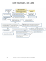
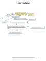
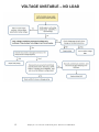
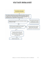
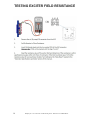
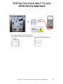
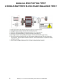
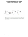
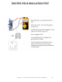
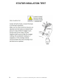
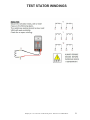
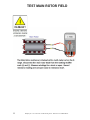
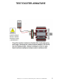
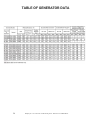
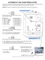
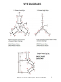
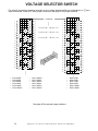
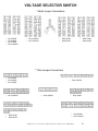
1
SERVICE TRAINING ® DCA GENERATOR TROUBLESHOOTING GUIDE ○ TROUBLESHOOTING ○ Manual No. DCATRBLSHOOT CALIFORNIA Proposition 65 Warning: Engine exhaust and some of its constituents, and some dust created by power sanding, sawing, grinding, drilling and other construction activities contains chemicals known to the State of California to cause cancer, birth defects and other reproductive harm. Some examples of these chemicals are: Lead and lead-based paint. Crystalline silica from bricks. Cement and other masonry products. Arsenic and chromium from chemically treated lumber. Your risk from these exposures varies, depending on how often you do this type of work. To reduce your exposure to these chemicals: ALWAYS work in a well ventilated area, and work with approved safety equipment, such as dust mask that are specially designed to filter out microscopic particles. 2 Multiquip Inc. ◦ DCA Generators Troubleshooting Guide ◦ Manual No. DCATRBLSHOOT IMPORTANT! Read the operator's manual for safety instructions before you attempt to troubleshoot. Use extreme caution when troubleshooting power equipment. Never start or run power equipment inside a closed area, breathing exhaust fumes can kill. Basically, a tool is an object that enables you to take advantage of the laws of physics and mechanics in such a way that you can seriously injure yourself. This training manual is intended to provide information and procedures to safely troubleshoot and give a basic understanding of troubleshooting techniques for the DCA series generators. You must be familiar with the operations of the DCA series generator before attempting to troubleshoot or make repairs. Basic operating and maintenance procedures are described in the operation and parts manual supplied with the generator. Use the supplied manual to order replacement parts. If you are missing the operation and parts manual, please contact Multiquip Inc to order a replacement or you may visit our website at www.multiquip.com For your safety and the safety of others carefully read, understand and observe all instruction described in this manual. Safety precautions should be followed at all times when servicing equipment. Consult operations manual for more safety information. THIS GUIDE IS USED FOR TRAINING PURPOSE ONLY AND NOT FOR GENERAL DISTRIBUTION Multiquip Inc. ◦ DCA Generators Troubleshooting Guide ◦ Manual No. DCATRBLSHOOT 3 SAFETY PLEASE REMEMBER SAFETY FIRST!!!!!!!!!!!!! This troubleshooting guide emphasizes safety precautions necessary during operation and testing. Safety precautions should be followed at all times when operating, maintaining and testing power equipment. Failure to read and understand safety precautions and warnings could result in injury to yourself and others. PLEASE READ ALL SAFETY PRECAUSIONS AND WARNINGS LISTED IN THE SECTION MARKED SAFETY BEFORE OPERATING, SERVICNG OR TESTING THIS EQUIPMENT. If you are not sure of the instructions or procedures, seek qualified help before continuing. This manual is not intended to be a substitute for properly trained personnel. Repairs should only be attempted by qualified, trained technicians. Each installation, application and operations of generators can create its own set of circumstances. No manual can cover every possible situation. When in doubt, ask. There is no such thing as dumb questions. BE SAFE!!!!!!! The following tests should only be carried out by qualified and/or experienced technician who have received SAFETY TRAINING ON LIVE EQUIPMENT. All test instruments and their leads / connectors / probes must be checked to ensure that they are suitable for the voltage levels being tested, and are in good working order. Whenever the generator is running, always assume and proceed as if voltage is present at the generator leads and at the regulator panel connections. Caution must be observed. Otherwise, serious personal injury or death can result. Before any work is done, and testing is conducted appropriate measure should be taken to prevent unexpected start-up of the generator. ALWAYS DISABLE ENGINE BEFORE WORKING INSIDE A GENERATOR TO PREVENT ACCIDENTIAL STARTUP! Proper grounding is necessary to help prevent shock if the frame becomes energized during live testing. Residual voltage is present at the generator leads, selector switch, circuit breaker, gages and at the regulator panel connections, even with the regulator disconnected or fuse removed. Caution must be observed or serious personal injury or death can result. Consult qualified personnel with any questions. Always wear proper PPE when conducting live voltage tests 4 Multiquip Inc. ◦ DCA Generators Troubleshooting Guide ◦ Manual No. DCATRBLSHOOT CONTENTS Troubleshooting Charts ………………………………………………………………………….…….6 o No Voltage – Residual Voltage Only…………..……………………………………………..7 o No Voltage…………..…………………………………………………………………………..8 o Low Voltage – No Load …………..………………….………………………………………..9 o Low Voltage – On Load …………..………………….……………………………………….10 o High Voltage …………..………………….……………………………………………...…….11 o Voltage Unstable – No Load …………..………………….………………………………….12 o Voltage Unbalance …...………………….……………………………………………...…….13 TROUBLESHOOTING PROCEDURES Testing Exciter Field Resistance ……………………………………………………………………..14 Testing Voltage Input to AVR – Open Delta Windings ……………………………………………..15 Manual Excitation Test – Using a Battery & Voltage Balance Test …..…………………………..16 Rotating Rectifier Test ……………………………………………………….………………………..17 Testing Rotating Rectifier Using a 12V DC Test Light ……………………………………….……..18 Exciter Field Insulation Test ………………………………………….………………………………..19 Stator Insulation Test …………………………………………………………………………………..20 Test Stator Windings …………………………………………….……………………………………..21 Test Main Rotor Field …………………………………………………………………………………..22 Test Exciter Armature …………………………………………………………………………………..23 DATA CHARTS Table of Generator Data ……………………………..………………………………………………...24 Automatic Voltage Regulator …………..…..………………………………………………………….25 Gen-Set Data .………………………….…..………………………………………………………….26 WYE Diagrams .………………………….…..……………………………………….……………….27 Voltage Selector Switch Automatic Voltage Regulator ………………………………..………..28-29 GENERATOR GLOSSARY Index ……………………………………………………………………………………..……..……….30 Multiquip Inc. ◦ DCA Generators Troubleshooting Guide ◦ Manual No. DCATRBLSHOOT 5 TROUBLESHOOTING CHARTS This manual is intended to suggest a systematic approach to locating and correcting generator malfunctions. The steps have been arranged in an attempt to do the easy checks first and prevent further damage when troubleshooting a disabled machine. The first step of troubleshooting is to gather as much information as is possible from operating personnel and individuals present during the failure. Typical information includes: How long the unit had been operating; What voltage was the generator running at when the fault occurred; What loads were on line; Information about the application the generator was operating is sometimes crucial to determine fault and cause of fault; Prior issues with machine; Maintenance history; Weather conditions; Protective equipment that did or did not function; In addition, information as to the operating condition of the generator's prime mover is vital. Has the prime mover been maintaining constant speed? If not, have there been extended periods of under speed operation? Has the prime mover experienced an over-speed condition? If yes, what was the maximum speed, and how long did the unit operate at that elevated speed? The generator speed should be maintained at rated nameplate value during all operating tests. The frequency of the generator depends upon rotational speed. Always make a thorough visual inspection to check for obvious problems before attempting to run the generator. Remove covers and look for any obvious problems. Burnt windings, broken connectors, burnt wires, mounting brackets, etc., can usually be identified through inspection. Look for any loose or frayed insulation, loose or dirty connections and broken wires. Check for any foreign objects, loose nuts, bolts and electrical connections. If possible rotate the generator rotor by hand to be sure it turns freely. If serious problems can be identified before attempting to operate the machine, additional damage can be avoided. 6 Multiquip Inc. ◦ DCA Generators Troubleshooting Guide ◦ Manual No. DCATRBLSHOOT NO VOLTAGE – RESIDUAL VOLTAGE ONLY Multiquip Inc. ◦ DCA Generators Troubleshooting Guide ◦ Manual No. DCATRBLSHOOT 7 NO VOLTAGE 8 Multiquip Inc. ◦ DCA Generators Troubleshooting Guide ◦ Manual No. DCATRBLSHOOT LOW VOLTAGE – NO LOAD Multiquip Inc. ◦ DCA Generators Troubleshooting Guide ◦ Manual No. DCATRBLSHOOT 9 LOW VOLTAGE – ON LOAD 10 Multiquip Inc. ◦ DCA Generators Troubleshooting Guide ◦ Manual No. DCATRBLSHOOT HIGH VOLTAGE Multiquip Inc. ◦ DCA Generators Troubleshooting Guide ◦ Manual No. DCATRBLSHOOT 11 VOLTAGE UNSTABLE – NO LOAD 12 Multiquip Inc. ◦ DCA Generators Troubleshooting Guide ◦ Manual No. DCATRBLSHOOT VOLTAGE UNBALANCE Multiquip Inc. ◦ DCA Generators Troubleshooting Guide ◦ Manual No. DCATRBLSHOOT 13 TESTING EXCITER FIELD RESISTANCE 14 Multiquip Inc. ◦ DCA Generators Troubleshooting Guide ◦ Manual No. DCATRBLSHOOT TESTING VOLTAGE INPUT TO AVR OPEN DELTA WINDINGS Multiquip Inc. ◦ DCA Generators Troubleshooting Guide ◦ Manual No. DCATRBLSHOOT 15 MANUAL EXCITATION TEST USING A BATTERY & VOLTAGE BALANCE TEST 16 Multiquip Inc. ◦ DCA Generators Troubleshooting Guide ◦ Manual No. DCATRBLSHOOT ROTATING RECTIFIER TEST Multiquip Inc. ◦ DCA Generators Troubleshooting Guide ◦ Manual No. DCATRBLSHOOT 17 TESTING ROTATING RECTIFIER USING A 12V DC TEST LIGHT 18 Multiquip Inc. ◦ DCA Generators Troubleshooting Guide ◦ Manual No. DCATRBLSHOOT EXCITER FIELD INSULATION TEST Multiquip Inc. ◦ DCA Generators Troubleshooting Guide ◦ Manual No. DCATRBLSHOOT 19 STATOR INSULATION TEST 20 Multiquip Inc. ◦ DCA Generators Troubleshooting Guide ◦ Manual No. DCATRBLSHOOT TEST STATOR WINDINGS Multiquip Inc. ◦ DCA Generators Troubleshooting Guide ◦ Manual No. DCATRBLSHOOT 21 TEST MAIN ROTOR FIELD 22 Multiquip Inc. ◦ DCA Generators Troubleshooting Guide ◦ Manual No. DCATRBLSHOOT TEST EXCITER ARMATURE Multiquip Inc. ◦ DCA Generators Troubleshooting Guide ◦ Manual No. DCATRBLSHOOT 23 TABLE OF GENERATOR DATA 24 Multiquip Inc. ◦ DCA Generators Troubleshooting Guide ◦ Manual No. DCATRBLSHOOT AUTOMATIC VOLTAGE REGULATOR There are four connectors that attach to the AVR and two wires to the AVR terminals. The AVR also has three potentiometers, only one is for course adjustment the other two should NOT be touched. IMORTANT: There is no procedure for directly testing the AVR, use process of elimination. 8 amp fuse MQ part # 6978K753 Open delta leads and excitation leads connect to the AVR on this connector. DCA 25 ONLY A ~ Wire is – YELLOW B ~ Wire is – ORANGE C ~ Wire is – WHITE D ~ Wire is – GRAY J ~ Wire is – RED K ~ Wire is – BLUE DCA 45 to DCA 150 A ~ Wire is labeled ~ A B ~ Wire is labeled ~ B C ~ Wire is labeled ~ C D ~ Wire is labeled ~ D J ~ Wire is labeled ~ J K ~ Wire is labeled ~ K (wires colors are black) This connector has no outside connection and has a couple of bridge jumper wires. P1, P2 ~ Wire is WHITE and are bridged together. ℓ, K ~ Wire is WHITE and are bridged together. Wires connected here are for AVR internal sensing. Two WHITE wires from the V-Leg Relay are connected here. U ~ Wire is RED and is connected to terminal # 14 on the voltage selector switch. V ~ Wire is WHITE and is connected to V-Leg Relay (RY1) W ~ Wire is BLUE and is connected to terminal # 36 on the voltage selector switch. This potentiometer (pot) is the voltage course adjustment pot. This connects the Rheostat (VR) to the AVR. 1 ~ Wire is GRAY 3 ~ Wire is YELLOW VISUAL REMINDER: The pots are positioned similar to a backwards capital letter ‘L’ DO NOT! adjust the other two pots, these are factory pre-set. Multiquip Inc. ◦ DCA Generators Troubleshooting Guide ◦ Manual No. DCATRBLSHOOT 25 GEN-SET DATA The chart below can be used as a reference guide for measuring resistance on the Gen-Set CROSS REFERENCE CHART RESISTANCE MEASURED IN OHMS Ω Main Armature Generator Gen-Set Model # Model # DCA-25SSAI AVR Inputs Main Exciter Armature Field Armature Field AC Outputs DC+ DC- UVW J+ K- 0.14 2 0.47 51 - A-B Field 2 B-C C-D D-A 51 0.9 2.7 DCA-25SSI DB-0281 0.155 1.09 0.16 14 - 0.83 2.5 DCA-25SSI2 DF-0270 0.124 4 0.3 17.6 - 0.9 2.7 DCA-25SSIU / SSIU2 DF-0270 0.124 4 0.3 17.6 - 0.9 2.7 DCA-25USI / USI2 DF-0270 DCA-40SSAI - 0.124 4 0.3 17.6 - 0.9 2.7 0.1074 0.143 0.143 13 13 0.5 1.5 DCA-40SSI DB-0501 0.082 1.46 0.21 15 - 0.74 2.22 DCA-45SSIU DB-0501 0.082 1.46 0.21 15 - 0.74 2.22 DCA-45SSIU2 / SSJU3 DB-0501 0.082 1.46 0.21 15 - 0.74 2.22 DCA-45SSIU4 DH-0480 0.099 1.33 0.137 18.8 0.78 2.15 DCA-45USI DB-0501 0.082 1.46 0.21 15 0.74 2.22 DCA-45USI2 DH-0480 0.099 1.33 0.137 18.8 0.042 0.93 0.143 12 DCA-60SSAI - 12 0.78 2.15 0.41 1.25 DCA-60SSI / SSI2 DB-0661 0.048 1.8 0.21 15 - 0.61 1.83 DCA-70SSJU / SSJU2 DB-0831 0.032 1.2 0.08 17.3 - 0.37 1.11 DCA-70SSI / SSIU DB-0831 0.032 1.2 0.08 17.3 - 0.37 1.11 DCA-70SSIU2 DH-0750 0.046 1.79 0.137 18.8 - 0.67 1.85 DCA-70USJ / USI DB-0831 0.032 1.2 0.08 17.3 - 0.37 1.11 DCA-70USI2 DH-0750 0.046 1.79 0.137 18.8 - 0.67 1.85 DCA-85SSJU / SSJU2 DB-1001 0.021 1.33 0.08 17.3 - 0.32 0.96 DCA-85USJ /USJ2 DB-1001 0.021 1.33 0.08 17.3 - 0.32 0.96 DCA-85SSK / SSM DB-1001 0.021 1.33 0.08 17.3 - 0.32 0.96 DCA-100SSJU DB-1101 0.022 1.4 0.08 17.3 - 0.32 0.97 DCA-125SSK DB-1381 0.015 1.52 0.08 17.3 - 0.28 0.84 DCA-125SSM / SSM2 DB-1381 0.015 1.52 0.08 17.3 - 0.28 0.84 DCA-125SSJU DB-1381 0.015 1.52 0.08 17.3 - 0.28 0.84 DCA-125USJ / USI DB-1381 0.015 1.52 0.08 17.3 - 0.28 0.84 DCA-150SSK / SSK2 DB-1651 0.011 1.75 0.08 17.3 - 0.27 0.82 DCA-150SSM DB-1651 0.011 1.75 0.08 17.3 - 0.27 0.82 DCA-150SSJU / SSV DB-1651 0.011 1.75 0.08 17.3 - 0.27 0.82 DCA-150SSJU2 DB-1651 0.011 1.75 0.08 17.3 - 0.27 0.82 DCA-150USJ / USJ2 DB-1651 0.011 1.75 0.08 17.3 - 0.27 0.82 Name of Part Wires Location of Wires Measuring between AC Output leads Exciter Field J&K (connected to AVR) Exciter Armature UVW (connected to rotating rectifier) Main Field DC+ DC – (connected to rotating rectifier) Main Armature 12 Load Leads 4 Open Delta Leads (AC Outputs) (connected to AVR – A,B,C,D) 26 U1 to X1 U2 to X2 V1 to Y1 V2 to Y2 W1 to Z1 W2 to Z2 Multiquip Inc. ◦ DCA Generators Troubleshooting Guide ◦ Manual No. DCATRBLSHOOT WYE DIAGRAMS Multiquip Inc. ◦ DCA Generators Troubleshooting Guide ◦ Manual No. DCATRBLSHOOT 27 VOLTAGE SELECTOR SWITCH The internal connections between terminals on the voltage selector switch are indicated by an used are external *metal and **wire jumper connectors, see page 20 for jumper locations. 2 4 2 POSITION 6 4 6 1 2 1 2 3 3 4 5 4 6 5 6 7 8 10 – 9 Position 2: = 3 ø 480 / 277 7 Position 4: = 3 ø 240 / 139 12 13 14 13 16 15 – Position 6: = 1 ø 240 / 120 – 11 11 15 8 9 12 14 16 – 17 – 18 20 19 – 20 22 21 24 23 25 26 25 26 27 28 27 28 30 29 30 32 31 32 34 33 36 35 38 37 40 39 42 41 44 43 – 44 45 – 46 17 – 18 19 – 21 23 – 29 31 33 – 35 – 37 39 41 43 – 22 24 – 34 – 36 – DCA-25SSI DCA-45SSI DCA-60SSI DCA-70SSI DCA-70SSJ DCA-100SSJ o o o o o o DCA-100SSV DCA-125SSI DCA-125SSJ DCA-150SSI DCA-150SSJ DCA-150SSV 42 48 o o o o o o DCA-25USI DCA-45USI DCA-70USI DCA-85USI DCA-125USJ DCA-150USJ See page 20 for external jumper locations 28 38 40 47 o o o o o o 10 Multiquip Inc. ◦ DCA Generators Troubleshooting Guide ◦ Manual No. DCATRBLSHOOT also VOLTAGE SELECTOR SWITCH * Metal Jumper Connections o o o o DCA-25SSI DCA-45SSI DCA-70SSI DCA-100SSV o o DCA-150SSV DCA-150USJ o o DCA-25USI DCA-45USI DCA-70USI DCA-85USJ o o ** Wire Jumper Connections o o o DCA-25SSI DCA-45SSI DCA-70SSI o DCA-100SSV o o DCA-25USI DCA-45USI DCA-150USJ o o DCA-150SSV o o o DCA-70USI DCA-85USJ DCA-125USJ Multiquip Inc. ◦ DCA Generators Troubleshooting Guide ◦ Manual No. DCATRBLSHOOT 29 GENERATOR GLOSSARY Ammeter - An instrument that measures electric current in amperes. Amperage (Amps) - The strength of a electrical current measured in amperes. Armature - That part of a generator or of an electric motor in which a current is induced by a magnetic field. The armature usually consists of a series of coils or groups of insulated conductors surrounding a core of iron. See page 8 for more information. Automatic Voltage Regulator (AVR) - Increases or decreases exciter current for a more linear voltage and frequency. See open delta page 30 for more information. Brushless Design - The purpose of the generator brush is to absorb power from the rotating armature of a generator and supply it to the stationary part of the generator. These brushes have a short life due to erosion. Multiquip’s unique brush less design calls for lower maintenance and a longer generator life. See open delta page 30 for more information. Circuit Breaker (CB) - Connects and disconnects the generator output from the output terminals. It also protects the generator from short circuits or overloads. Exciter Armature - The exciter armature or just the "exciter", generates electricity which is used for excitation of the field coil. The field coil makes the magnetic field required to generate electricity, which is used for the generators main power output. Frequency - Frequency is the number of complete cycles per second in alternating current direction. The standard unit of frequency is the hertz, abbreviated Hz. If a current completes one cycle per second, then the frequency is 1 Hz; 60 cycles per second equals 60 Hz Ground Fault Interrupters (GFI's) - These devices are designed to eliminate electrical shock hazard resulting from individuals coming in contact with a hot AC line. The circuit interrupter is designed to sense any change in circuit conditions. It is required by the NEC that all 12 volt, single phase, 15- or 20 ampere receptacle outlets that are installed outdoors or in bathrooms have ground fault interrupters connected to them Heat Rise - Is in direct relation to the longetivity of the generator. To find out why Multiquip units exceed the competition, see page 27 KVA – Kilo Volt Amp which sizes three phase loads can be converted to Kilowatts by multiplying the KVA by the power factor 0.8 NEMA - National Electrical Manufacturers Association: For more information about NEMA and their standards, visit their website at http://www.nema.org/. Ohm - A unit of electrical resistance equal to that of a conductor in which a current of one ampere is produced by a potential of one volt across its terminals. 30 Multiquip Inc. ◦ DCA Generators Troubleshooting Guide ◦ Manual No. DCATRBLSHOOT GENERATOR GLOSSARY Phase Single Phase Power (typically 120V AC or 230V AC depending on the country) is carried between two wires: live and neutral and sometimes a third ground wire for safety. The frequency of AC voltage is 50 or 60 Hz depending on the country. Single-phase power is used in very many applications, for example to power all typical home electrical appliances you use single-phase power from a normal electrical outlet at home. Three Phase Power is very common and is a more efficient use of conductors. Voltage is carried through three conductors 120° out of phase with the other two. Three-phase power provides a more efficient means of supplying large electrical loads like motors, and is used more in industrial areas. PMG - Permanent Magnetic Generator: Eliminates the excitation losses in the rotor, which otherwise typically represent 20 to 30% of the total generator losses. It also gives a lower temperature rise in the generator. Rheostat - A continuously variable electrical resistor used to regulate current. Voltage - the rate at which energy is drawn from a source that produces a flow of electricity in a circuit. Expressed in volts (V) Voltmeter - This feature serves as a convenient diagnostic tool on the jobsite. The operator can quickly tell whether or not the generator is producing the correct voltage and prevent overheating of tools and equipment. Watt – An international system unit of power equal to one joule per second, the power dissipated by a current of 1 ampere flowing across a resistance of 1 ohm. A = Amps W = Watts kW = Kilowatts vA = Volt amps kVA = Kilovolt amps 1 Ø = Single Phase 3 Ø = Three Phase V = Volts dB = Decibels Hz = Frequency (hertz) Multiquip Inc. ◦ DCA Generators Troubleshooting Guide ◦ Manual No. DCATRBLSHOOT 31 Corporate Headquarters • Multiquip Inc. 18910 Wilmington Ave. Carson, Ca. 90746 32 Multiquip Inc. ◦ DCA Generators Troubleshooting Guide ◦ Manual No. DCATRBLSHOOT