1
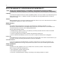
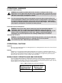
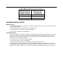
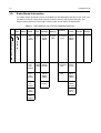
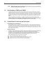
Professional Radio
GM Series
Detailed Service Manual
6864115B62-B
ii
Professional Radio
GM Series
Detailed Service Manual
6864115B62-B
Contents
Section 1
Service Maintainability
Section 2
Controlhead Service Information
Section 3
Controller Service Information
Section 4
VHF Service Information
Section 5
UHF Service Information
Section 6
Lowband Service Information
WLS EMEA Publications Department, Jays Close, Viables Industrial Estate, Basingstoke, Hampshire, RG22 4PD, UK.
Issue : August 2002
iii
iv
Professional Radio
GM Series
Service Maintainability
Issue: August 2002
ii
Computer Software Copyrights
The Motorola products described in this manual may include copyrighted Motorola computer programs stored
in semiconductor memories or other media. Laws in the United States and other countries preserve for
Motorola certain exclusive rights for copyrighted computer programs, including the exclusive right to copy or
reproduce in any form, the copyrighted computer program. Accordingly, any copyrighted Motorola computer
programs contained in the Motorola products described in this manual may not be copied or reproduced in
any manner without the express written permission of Motorola. Furthermore, the purchase of Motorola
products shall not be deemed to grant, either directly or by implication, estoppel or otherwise, any license
under the copyrights, patents or patent applications of Motorola, except for the normal non-exclusive
royalty-free license to use that arises by operation of law in the sale of a product.
iii
Table of Contents
Chapter 1
INTRODUCTION
1.0 Scope of Manual ..................................................................................................1-1
2.0 Warranty and Service Support.............................................................................1-1
2.1 Warranty Period and Return Instructions .......................................................1-1
2.2 After Warranty Period .....................................................................................1-1
2.3 European Radio Support Centre (ERSC).......................................................1-2
2.4 Parts Identification and Ordering ....................................................................1-2
2.5 EMEA Test Equipment Support......................................................................1-2
2.6 Technical Support...........................................................................................1-3
2.7 Related Documents ........................................................................................1-3
3.0 Radio Model Information......................................................................................1-4
Chapter 2
MAINTENANCE
1.0 Introduction ..........................................................................................................2-1
2.0 Preventive Maintenance ......................................................................................2-1
2.1 Inspection .......................................................................................................2-1
2.2 Cleaning .........................................................................................................2-1
3.0 Safe Handling of CMOS and LDMOS..................................................................2-2
4.0 General Repair Procedures and Techniques.......................................................2-2
5.0 Notes For All Schematics and Circuit Boards ......................................................2-5
Chapter 3
SERVICE AIDS
1.0 Recommended Test Tools...................................................................................3-1
2.0 Test Equipment....................................................................................................3-2
iv
v
SAFETY AND GENERAL INFORMATION
IMPORTANT INFORMATION ON SAFE AND EFFICIENT OPERATION
Read this infomation before using your radio.
The information provided in this document supersedes the general safety information contained in user guides
published prior to July 2000. For information regarding radio use in a hazardous atmosphere please refer to the
Factory Mutual (FM) Approval Manual Supplement or Instruction Card, which is included with radio models that
offer this capability.
Radio Frequency (RF) Operational Characteristics
To transmit (talk) you must push the Push-To-Talk button; to receive (listen) you must release the Push-To-Talk
button. When the radio is transmitting, it generates radio frequency (RF) energy; when it is receiving, or when it
is off, it does not generate RF energy.
PORTABLE RADIO OPERATION AND EME EXPOSURE
Your Motorola radio is designed to comply with the following national and international standards and guidelines
regarding exposure of human beings to radio frequency electromagnetic energy:
●
●
●
●
●
●
●
United States Federal Communications Commission, Code of Federal Regulations; 47 CFR part 2 sub-part J
American National Standards Institute (ANSI) / Institute of Electrical and Electronic Engineers (IEEE)
C95. 1-1992
Institute of Electrical and Electronic Engineers (IEEE) C95.1-1999 Edition
National Council on Radiation Protection and Measurements (NCRP) of the United States, Report 86, 1986
International Commission on Non-Ionizing Radiation Protection (ICNIRP) 1998
Ministry of Health (Canada) Safety Code 6. Limits of Human Exposure to Radiofrequency Electromagnetic
Fields in the Frequency Range from 3 kHz to 300 GHz, 1999
Australian Communications Authority Radiocommunications (Electromagnetic Radiation - Human Exposure)
Standard 1999 (applicable to wireless phones only)
To assure optimal radio performance and make sure human exposure to radio frequency electromagnetic energy
is within the guidelines set forth in the above standards, always adhere to the following procedures:
Phone operation
When placing or receiving a phone call, hold your phone as you would a wireline telephone. Speak directly into
the microphone.
Two-way radio operation
When using your radio hold the radio in a vertical position with the microphone 2.5 to 5 cm away from the lips.
Body-worn operation
To maintain compliance with FCC RF exposure guidelines, if you wear a radio on your body when transmitting,
always place the radio in a Motorola approved clip, holder, holster, case, or body harness for this product. Use of
non-Motorola-approved body worn accessories may exceed FCC RF exposure guidelines. If you do not use a
Motorola approved body-worn accessory and are not using the radio in the intended use positions along side of
the head in the phone mode or in front of the face in the two-way radio mode, then ensure the antenna and radio
is kept the following minimum distances from the body when transmitting:
●
●
Phone or Two-way radio mode: 2.5 cm (one inch)
Data operation using any data feature with or without an accessory cable: 2.5 cm (one inch) .
Antenna Care
Use only the supplied or an approved replacement antenna. Unauthorized antennas, modifications, or
attachments could damage the radio and may violate FCC regulations.
DO NOT hold the antenna when the radio is "IN USE". Holding the antenna affects call quality and may cause
the radio to operate at a higher power level than needed.
Approved Accessories
For a list of approved Motorola accessories please contact your dealer or local Motorola representative.
vi
ELECTROMAGNETIC INTERFERENCE/COMPATIBILITY
NOTE Nearly every electronic device is susceptible to electromagnetic interference (EMI) if
inadequately shielded, designed, or alternately configured for electromagnetic compatibility.
Facilities
To avoid electromagnetic interference and/or compatibility conflicts, turn off your radio in any facility where posted
notices instruct you to do so. Hospitals or health care facilities may be using equipment that is sensitive to
external RF energy.
Aircraft
When instructed to do so, turn off your radio when on board an aircraft. Any use of a radio must be in accordance
with applicable regulations per airline crew instructions.
Medical Devices
Pacemakers
The Health Industry Manufacturers Association recommends that a minimum separation of 15 cms
(6 inches) be maintained between a handheld wireless radio and a pacemaker.These recommendations are
consistent with those of the U.S. Food and Drug Administration.
Persons with pacemakers should:
●
●
●
●
ALWAYS keep the radio more than 15 cms (6inches) from their pacemaker when the radio is turned ON.
not carry the radio in the breast pocket.
use the ear opposite the pacemaker to minimize the potential for interference.
turn the radio OFF immediately if you have any reason to suspect that interference is taking place.
Hearing Aids
Some digital wireless radio products may interfere with some hearing aids. In the event of such interference, you
may want to consult your hearing aid manufacturer to discuss alternatives.
Other Medical Devices
If you use any other personal medical device, consult the manufacturer of your device to determine if it is
adequately shielded from RF energy. Your physician may be able to assist you in obtaining this information.
Safety and General
Use While Driving
Check the laws and regulations on the use of radios in the area where you drive. Always obey them.
When using your radio while driving, please:
●
●
●
Give full attention to driving and to the road.
Use hands-free operation, if available.
Pull off the road and park before making or answering a call if driving conditions so require.
vii
OPERATIONAL WARNINGS
For Vehicles With An Air Bag
!
NOTE
WARNING: Do not place a portable radio in the area over an air bag or in the air bag
deployment area. Air bags inflate with great force. If a portable radio is placed in the air bag
deployment area and the air bag inflates, the radio product may be propelled with great force
and cause serious injury to occupants of vehicle.
The areas with potentially explosive atmospheres referred to above include fueling areas
such as below decks on boats, fuel or chemical transfer or storage facilities, areas where the
air contains chemicals or particles, such as grain, dust or metal powders, and any other
area where you would normally be advised to turn off your vehicle engine. Areas with potentially explosive atmospheres are often but not always posted.
Potentially Explosive Atmospheres
!
WARNING: Turn off your radio prior to entering any area with a potentially explosive
atmosphere, unless it is a radio type especially qualified for use in such areas as
"Intrinsically Safe" (for example, Factory Mutual, CSA, UL or CENELEC Approved). Do not
remove, install, or charge batteries in such areas. Sparks in a potentially explosive
atmosphere can cause an explosion or fire resulting in bodily injury or even death.
Blasting Caps And Areas
!
WARNING: To avoid possible interference with blasting operations, turn off your radio when
you are near electrical blasting caps, in a “blasting area” or in areas posted
“Turn off two-way radio”. Obey all signs and instructions.
OPERATIONAL CAUTIONS
Antennas
Do not use any portable radio that has a damaged antenna. If a damaged antenna comes into contact with your
skin, a minor burn can result.
Batteries
All batteries can cause property damage and/or bodily injury such as burns if a conductive material such as
jewellery, keys, or beaded chains touch exposed terminals. The conductive material may complete an electrical
circuit (short circuit) and become quite hot. Exercise care in handling any charged battery, particularly when
placing it inside a pocket, purse, or other container with metal objects.
MOBILE RADIO OPERATION AND EME EXPOSURE
To assure optimal radio performance and that human exposure to radio frequency electromagnetic energy is
within the guidelines referenced earlier in this document, transmit only when people outside the vehicle are at
least the minimum lateral distance away from a properly installed, externally-mounted antenna. Table 1 lists the
minimum distance for several different ranges of rated radio power.
Table 1: Table 1 Rated Power and Lateral Distance
Radiated Power of
Vehicle-installed
Mobile Two-way
Less than 7 Watts
Minimum Lateral
Distance From
Transmitting
20 cm (8 Inches)
viii
Table 1: Table 1 Rated Power and Lateral Distance
Radiated Power of
Vehicle-installed
Mobile Two-way
Minimum Lateral
Distance From
Transmitting
7 to 15 Watts
30 cm (1 Ft)
16 to 50 Watts
60 cm (2 Ft)
More than 50 Watts
90 cm (3 Ft)
ANTENNA INSTALLATION
Mobile Antennas
Recommended mobile antenna installations are limited to metal body vehicles at the centre of the roof and centre
of the trunk deck locations.
The antenna installation must additionally be in accordance with:
a) The requirements of the antenna manufacturer/supplier
b) Instructions in the Radio Installation Manual
Fixed Site Antennas
Mobile radio equipment is sometimes installed at a fixed location and operated as a control station or as a fixed
unit. In such cases the antenna installation must comply with the following requirements in order to assure
optimal performance and make sure human exposure to radio frequency electromagnetic energy is within the
guidelines set forth in the above standards:
●
●
●
The antenna must be mounted outside the building
Mount the antenna on a tower if at all possible
If the antenna is to be mounted on a building then it must be mounted on the roof.
As with all fixed site antenna installations, it is the responsibility of the licensee to manage the site in accordance
with applicable regulatory requirements and may require additional compliance actions such as site survey
measurements, signage, and site access restrictions in order to insure that exposure limits are not exceeded.
Chapter 1
INTRODUCTION
1.0
Scope of Manual
This manual is intended for use by service technicians familiar with similar types of equipment. It
contains service information required for the equipment described and is current as of the printing
date. Changes which occur after the printing date may be incorporated by a complete Manual
revision or alternatively as additions.
NOTE Before operating or testing these units, please read the Safety Information Section in the
front of this manual.
2.0
Warranty and Service Support
Motorola offers long term support for its products. This support includes full exchange and/or repair
of the product during the warranty period, and service/ repair or spare parts support out of warranty.
Any "return for exchange" or "return for repair" by an authorised Motorola Dealer must be
accompanied by a Warranty Claim Form. Warranty Claim Forms are obtained by contacting an
Authorised Motorola Dealer.
2.1
Warranty Period and Return Instructions
The terms and conditions of warranty are defined fully in the Motorola Dealer or Distributor or
Reseller contract. These conditions may change from time to time and the following notes are for
guidance purposes only.
In instances where the product is covered under a "return for replacement" or "return for repair"
warranty, a check of the product should be performed prior to shipping the unit back to Motorola.
This is to ensure that the product has been correctly programmed or has not been subjected to
damage outside the terms of the warranty.
Prior to shipping any radio back to the appropriate Motorola warranty depot, please contact
Customer Resources (Please see page 2 and page 3 in this Chapter). All returns must be
accompanied by a Warranty Claim Form, available from your Customer Services representative.
Products should be shipped back in the original packaging, or correctly packaged to ensure no
damage occurs in transit.
2.2
After Warranty Period
After the Warranty period, Motorola continues to support its products in two ways.
1.
Motorola's Radio Aftermarket and Accessory Division (AAD) offers a repair service to both
end users and dealers at competitive prices.
2.
AAD supplies individual parts and modules that can be purchased by dealers who are technically capable of performing fault analysis and repair.
1-2
2.3
INTRODUCTION
European Radio Support Centre (ERSC)
The ERSC Customer Information Desk is available through the following service numbers:
Austria:
06 60 75 41
Italy:
16 78 77 387
Belgium:
08 00 72 471
Luxemburg:
08 00 23 27
Denmark:
80 01 55 72
Netherlands:
60 22 45 13
Finland:
08 00 11 49 10
Norway:
80 01 11 15
France:
05 90 30 90
Portugal:
05 05 49 35 70
Germany:
08 00 18 75 240
Spain:
90 09 84 902
Greece:
00 80 04 91 29 020
Sweden:
02 07 94 307
UK:
08 00 96 90 95
Switzerland:
1 55 30 82
Ireland:
18 00 55 50 21
Iceland:
80 08 147
Or dial Customer Care Centre:
Tel: +49 6128 70 2618
Please use these numbers for repair enquiries only.
2.4
Parts Identification and Ordering
Request for help in identification of non-referenced spare parts should be directed to the Customer
Care Organisation of Motorola’s local area representation. Orders for replacement parts, kits and
assemblies should be placed directly on Motorola’s local distribution organisation or via Motorola
Online (Extranet).
2.5
EMEA Test Equipment Support
Information related to support and service of Motorola Test Equipment is available via Motorola
Online (Extranet), through the Customer Care Organisation of Motorola’s local area representation
or by calling the Motorola switchboard in Germany on telephone number: +49 6128 700.
Warranty and Service Support
2.6
1-3
Technical Support
Motorola Product Services is available to assist the dealer/distributors in resolving any malfunctions
which may be encountered.
UK/Ireland - Richard Russell
Telephone: +44 (0) 1256 488 082
Fax: +44 01256 488 080
Email: [email protected]
France - Lionel Lhermitte
Telephone: +33 1 6929 5722
Fax: +33 1 6929 5904
Email: [email protected]
East Europe, Turkey and Central Asia
Siggy Punzenberger
Telephone: +49 (0) 6128 70 2342
Fax: +49 (0) 6128 95 1096
Email: [email protected]
Italy - Ugo Gentile
Telephone: +39 0 2822 0325
Fax: +39 0 2822 0334
Email: [email protected]
Russian Regional Repair Operations:
Telephone: +7 095 785 01 89
2.7
Scandinavia
Telephone: +46 8 735 9282
Fax: +46 8 735 9280
Email: [email protected]
Middle East & Africa - Ralph Schubert
Telephone: +33 (0) 4 4230 5887
Fax: +33 (0) 4 4230 4784
Email: [email protected]
Central Europe (Germany, Benelux,
Austria & Switzerland) - Customer Connect
Telephone: +49 (0) 6128 70 2248
Fax: +49 (0) 6128 95 1082
Email: [email protected]
Motorola Support Centre South Africa:
Telephone: +27 11 254 4000
Related Documents
The following documents are directly related to the use and maintainability of this product.
Title
Language
Part Number
GM100 Series Product Manual
English
ENLN4147
GM300 Series Product Manual
English
German
French
Italian
Spanish
Russian
ENLN4137
ENLN4138
ENLN4139
ENLN4140
ENLN4141
ENLN4142
GM600/GM1200 Series Product Manual
English
German
French
Russian
ENLN4143
ENLN4144
ENLN4145
ENLN4146
1-4
3.0
INTRODUCTION
Radio Model Information
The model number and serial number are located on a label attached to the back of your radio. You
can determine the RF output power, frequency band, protocols, and physical packages. The
example below shows one mobile radio model number and its specific characteristics.
Table 1-1 Radio Model Number (Example: MDM25KHC9AN1AE)
Type of Model
Unit
Series
M
25
Power
Level
Physical
Packages
Channel
Spacing
Protocol
K
VHF
(136174MHz)
H
1-25W
C
GM140,
GM340,
GM640
9
Programmable
R
K
UHF 1 25-40W
(40340-60W
470MHz)
Feature
Level
Model
Revision
Model
Package
AN
Conventional
5 Tone
1
GM140
GM340
GM640
A
E
N
GM380,
GM1280
AA
Conventional
MDC
O
Databox
(5Tone)
S
UHF 2
(450527MHz)
F
GM160
GM360
GM660
CK
MPT
5
GM160
GM360
GM660
B
LB1
29-36MHz
A
Databox
M = Mobile
MD = Motorola Internal Use
MD
Freq.
Band
C
LB2
36-42MHz
D
LB3
42-50MHz
8
GM380
GM1280
7
Databox
(MPT)
Chapter 2
MAINTENANCE
1.0
Introduction
This chapter of the manual describes:
2.0
■
preventive maintenance
■
safe handling of CMOS devices
■
repair procedures and techniques
Preventive Maintenance
The radios do not require a scheduled preventive maintenance program; however, periodic visual
inspection and cleaning is recommended.
2.1
Inspection
Check that the external surfaces of the radio are clean, and that all external controls and switches
are functional. It is not recommended to inspect the interior electronic circuitry.
2.2
Cleaning
The following procedures describe the recommended cleaning agents and the methods to be
used when cleaning the external and internal surfaces of the radio. External surfaces include the
front cover, housing assembly, and battery case. These surfaces should be cleaned whenever a
periodic visual inspection reveals the presence of smudges, grease, and/or grime.
NOTE
Internal surfaces should be cleaned only when the radio is disassembled for servicing or
repair.
The only recommended agent for cleaning the external radio surfaces is a 0.5% solution of a mild
dishwashing detergent in water. The only factory recommended liquid for cleaning the printed
circuit boards and their components is isopropyl alcohol (70% by volume).
!
CAUTION: The effects of certain chemicals and their vapors can have harmful results on
certain plastics. Aerosol sprays, tuner cleaners, and other chemicals should be avoided.
1.
Cleaning External Plastic Surfaces
The detergent-water solution should be applied sparingly with a stiff, non-metallic, shortbristled brush to work all loose dirt away from the radio. A soft, absorbent, lintless cloth or
tissue should be used to remove the solution and dry the radio. Make sure that no water
remains entrapped near the connectors, cracks, or crevices.
2.
Cleaning Internal Circuit Boards and Components
Isopropyl alcohol may be applied with a stiff, non-metallic, short-bristled brush to dislodge
embedded or caked materials located in hard-to-reach areas. The brush stroke should
direct the dislodged material out and away from the inside of the radio. Make sure that
controls or tunable components are not soaked with alcohol. Do not use high-pressure
air to hasten the drying process since this could cause the liquid to collect in unwanted
places. Upon completion of the cleaning process, use a soft, absorbent, lintless cloth to
dry the area. Do not brush or apply any isopropyl alcohol to the frame, front or back cover.
2-2
MAINTENANCE
NOTE
3.0
Always use a fresh supply of alcohol and a clean container to prevent contamination by
dissolved material (from previous usage).
Safe Handling of CMOS and LDMOS
Complementary metal-oxide semiconductor (CMOS) devices are used in this family of radios.
CMOS characteristics make them susceptible to damage by electrostatic or high voltage charges.
Damage can be latent, resulting in failures occurring weeks or months later. Therefore, special
precautions must be taken to prevent device damage during disassembly, troubleshooting, and
repair.
Handling precautions are mandatory for CMOS circuits and are especially important in low
humidity conditions. DO NOT attempt to disassemble the radio without first referring to the CMOS
CAUTION paragraph in the Disassembly and Reassembly section of the manual.
4.0
General Repair Procedures and Techniques
Parts Replacement and Substitution
When damaged parts are replaced, identical parts should be used. If the identical replacement
component is not locally available, check the parts list for the proper Motorola part number and
order the component from the nearest Motorola Communications parts center listed in the “Piece
Parts” section of this manual.
Rigid Circuit Boards
The family of radios uses bonded, multi-layer, printed circuit boards. Since the inner layers are not
accessible, some special considerations are required when soldering and unsoldering
components. The through-plated holes may interconnect multiple layers of the printed circuit.
Therefore, care should be exercised to avoid pulling the plated circuit out of the hole.
When soldering near the 18-pin and 40-pin connectors:
■
avoid accidentally getting solder in the connector.
■
be careful not to form solder bridges between the connector pins
■
closely examine your work for shorts due to solder bridges.
General Repair Procedures and Techniques
2-3
Chip Components
Use either the RLN4062 Hot-Air Repair Station or the Motorola 0180381B45 Repair Station for
chip component replacement. When using the 0180381B45 Repair Station, select the TJ-65 minithermojet hand piece. On either unit, adjust the temperature control to 370 °C (700 °F), and
adjust the airflow to a minimum setting. Airflow can vary due to component density.
■
■
■
To remove a chip component:
1.
Use a hot-air hand piece and position the nozzle of the hand piece approximately 0.3 cm
(1/8") above the component to be removed.
2.
Begin applying the hot air. Once the solder reflows, remove the component using a pair
of tweezers.
3.
Using a solder wick and a soldering iron or a power desoldering station, remove the
excess solder from the pads.
To replace a chip component using a soldering iron:
1.
Select the appropriate micro-tipped soldering iron and apply fresh solder to one of the
solder pads.
2.
Using a pair of tweezers, position the new chip component in place while heating the
fresh solder.
3.
Once solder wicks onto the new component, remove the heat from the solder.
4.
Heat the remaining pad with the soldering iron and apply solder until it wicks to the
component. If necessary, touch up the first side. All solder joints should be smooth and
shiny.
To replace a chip component using hot air:
1.
Use the hot-air hand piece and reflow the solder on the solder pads to smooth it.
2.
Apply a drop of solder paste flux to each pad.
3.
Using a pair of tweezers, position the new component in place.
4.
Position the hot-air hand piece approximately 0.3 cm (1/8” ) above the component and
begin applying heat.
5.
Once the solder wicks to the component, remove the heat and inspect the repair. All
joints should be smooth and shiny.
2-4
MAINTENANCE
Shields
Removing and replacing shields will be done with the R1070 station with the temperature control
set to approximately 215°C (415°F) [230°C (445°F) maximum].
■
■
To remove the shield:
1.
Place the circuit board in the R1070 circuit board holder.
2.
Select the proper heat focus head and attach it to the heater chimney.
3.
Add solder paste flux around the base of the shield.
4.
Position the shield under the heat-focus head.
5.
Lower the vacuum tip and attach it to the shield by turning on the vacuum pump.
6.
Lower the focus head until it is approximately 0.3 cm (1/8”) above the shield.
7.
Turn on the heater and wait until the shield lifts off the circuit board.
8.
Once the shield is off, turn off the heat, grab the part with a pair of tweezers, and turn off
the vacuum pump.
9.
Remove the circuit board from the R1070 circuit board holder.
To replace the shield:
1.
Add solder to the shield if necessary, using a micro-tipped soldering iron.
2.
Next, rub the soldering iron tip along the edge of the shield to smooth out any excess
solder. Use solder wick and a soldering iron to remove excess solder from the solder
pads on the circuit board.
3.
Place the circuit board back in the R1070 circuit board holder.
4.
Place the shield on the circuit board using a pair of tweezers.
5.
Position the heat-focus head over the shield and lower it to approximately 0.3 cm (1/8”)
above the shield.
6.
Turn on the heater and wait for the solder to reflow.
7.
Once complete, turn off the heat, raise the heat-focus head and wait approximately one
minute for the part to cool.
8.
Remove the circuit board and inspect the repair. No cleaning should be necessary.
Notes For All Schematics and Circuit Boards
5.0
2-5
Notes For All Schematics and Circuit Boards
* Component is frequency sensitive. Refer to the Electrical Parts List for value and usage.
1. Unless otherwise stated, resistances are in Ohms (k = 1000), and capacitances are in picofarads
(pF) or microfarads (µF).
2. DC voltages are measured from point indicated to chassis ground using a Motorola DC
multimeter or equivalent. Transmitter measurements should be made with a 1.2 µH choke in
series with the voltage probe to prevent circuit loading.
3. Interconnect Tie Point Legend:
16_8MHz
16.8MHz Reference Frequency
3V3
Regulated 3.3V Supply Voltage for Voice Storage
5V
Regulated 5V Supply Voltage for RF Circuitry
5V
Regulated 5V Supply Voltage (Control Head)
5V RF
Regulated 5V Supply Voltage for RF Circuitry
5V SOURCE
5V Signal to Switch On Control Head
5VD
Regulated 5V Supply Voltage for Digital Circuitry
9V3
Regulated 9.3V Supply Voltage
9V3FLT
Filtered 9.3V Supply Voltage
A+
13.2V Supply Voltage
ADDR
*P Address Lines
AN
Analog Lines to Analog to Digital Converter
ANALOG INPUT 2
External Keypad Matrix Column Signal
ANALOG INPUT 3
External Keypad Matrix Row Signal
BATTERY VOLTAGE
Battery Voltage Sense Line
BL A GREEN
Back Light Anode Green
BL A RED
Back Light Anode Red
BL GREEN
Green Back Light Control
BL K GREEN
Back Light Cathode Green
BL K RED
Back Light Cathode Red
BL KP Green
Green Keypad Back Light Control
BL KP RED
Red Keypad Back Light Control
BL LCD GREEN
Green Display Back Light Control
BL LCD RED
Red Display Back Light Control
BL RED
Red Back Light Control
BOOT CNTRL
Bootstrap Mode Enable Signal
BOOT MODE
Boot Mode Select
BOOT PWR ON
Control Head Switch On Signal
BOOT SCI RX
Serial Communication Interface Receive Line
BOOT SCI TX
Serial Communication Interface Transmit Line
BOOT VPP
Boot Mode Select
BUS+
Bi-directional Serial Communication Line
BWSELECT
Signal to select between the Ceramic Filter Pairs
2-6
MAINTENANCE
CH ACT
Channel Activity Indicator Signal (Fast Squelch)
CH KP ID
Control Head Keypad ID (Data) Lines
CH REQUEST
Control Head Request from Control Head *P
CLK
Clock Signal
CNTLVLTG
PA Power Control Voltage
CNTR AUDIO
Audio Lines of the Controller
COL x
Keypad Matrix Column x
CSX
Chip Select Line PCIC / FRACN
DATA
Data Signal
DC POWER ON
Electronic Switching On or Off of the Radio's Voltage Regulators
DISCAUDIO
Audio Output Signal from the Receiver IC
ECLK
Clock (not used)
EE CS
EEPROM Chip Select
EMERGENCY CONTROL
Emergency Line to switch on the Radio's Voltage Regulators
EXP BD REQ
Service Request Line from Expansion Board
EXP1 CS
Expansion Board Chip Select 1
EXP2 CS
Expansion Board Chip Select 2
EXT KP COL
External Keypad Matrix Column Signal
EXT KP ROW
External Keypad Matrix Row Signal
EXT MIC
External (from Accessory Connector) Microphone Input
EXT SWB+
External Switched 13.2V Supply Voltage
F1200
Interrupt Line from ASFIC CMP
FECTRL 1
Control Voltage for Front End Filter
FECTRL 2
Control Voltage for Front End Attenuator Switch
FLASH CE
Flash Chip Select
FLASH OE
Flash Output Enable
FLAT RX SND
Option Board Audio Output Signal
FLAT TX RTN
Flat TX Input from Option Board and Accessory Connector
FLT A+
Filtered 13.2 V Supply Voltage
GP x IN
General Purpose Input x
GP x IN ACC y
General Purpose Input x from Accessory Connector Pin y
GP x IN OUT ACC y
y
General Purpose Input /Output x from Accessory Connector Pin
GP x OUT
General Purpose Output x
GP x OUT ACC y
General Purpose Input x from Accessory Connector Pin y
GPIO
General Purpose Input Output Lines
HANDSET AUDIO
Handset Audio Output
HOOK
Hang-up Switch Input
HSIO
High Speed Clock In / Data Out
IF
First Intermediate Frequency Signal
IGNITION CONTROL
Ignition Line to switch on the Radio's Voltage Regulators
Notes For All Schematics and Circuit Boards
2-7
IN 5V RF REG
Supply Voltage for 5V Regulator in RF Section
INT KP COL
Internal Keypad Matrix Column Signal
INT KP ROW
Internal Keypad Matrix Row Signal
INT MIC
Internal (from Control Head) Microphone Input
INT SWB
Internal Switched 13.2V Supply Voltage
INT SWB+
Internal Switched 13.2V Supply Voltage
IRQ
Interrupt Request from Control Head
K9V1
9.1V in Transmit Mode
KEYPAD ID
Keypad Identification Line
LCD A0
LCD Control / Display Data Select
LCD CS
LCD Chip Select
LCD DATA
LCD Data Lines
LCD E RD
LCD Enable Read
LCD RW WR
LCD Read Write Control
LED CNTRL
LED Control Lines
LED GREEN
Green LED Control
LED RED
Red LED Control
LED YELLOW
Yellow LED Control
LOCK
Lock Detect Signal from Synthesizer
LSIO
Low Speed Clock In / Data Out
LVZIF CS
LVZIF Chip Select (not used)
MIC
Microphone Input
MISO
Serial Peripheral Interface Receive Line
MODIN
Modulation Signal into the Synthesizer
MOSBIAS 2
PA Bias Voltage for second Stage
MOSBIAS 3
PA Bias Voltage for third Stage
NOISE BLNKR
Noise Blanker Enable (Low Band only)
ON OFF CONTROL
Service Request Line from Control Head / Manual Switching On
of the Radio's Voltage Regulators
ON OFF SENSE (Control Head) On Off Sense Line to Control Head *P
ON OFF SENSE (Controller)
Service Request Line from Control Head
OPT CS
Option Board Chip Select
OPT PTT
PTT from Option Board
PA PWR SET
ASFIC Output Voltage to set the Transmitter Power
PA SWB
Switches Supply Voltage for PA Current Control Circuitry
PASUPVLTG
13.2 V Supply Voltage of the Transmitter PA
PCIC MOSBIAS 1
PA Bias Voltage for first Stage
PRESC
Prescaler Signal from VCO to Synthesizer
PTT IRDEC
Microphone PTT Input
PTT IRDECODER
Microphone PTT Input
RW
Read Write Signal for RAM / Flash
2-8
MAINTENANCE
RAM CS
RAM Ship Select
RDY
Service Request Line from Option Board
REF CS
Reference Chip Select (not used)
RESET
Reset Line
ROW x
Keypad Matrix Row x
RSSI
Received Signal Strength Indicator
RX ADAPT
Flat TX Path Disable during Transmitter Key-up
RX AUD RTN
Option Board Input / Output of Receiver Audio Path
RX FLAT FILTERED AUDIO
Flat or Filtered Audio to Accessory Connector
RXIN
RF Signal from Antenna Switch into the Receiver
RXINJ
RF Signal from the VCO into the Mixer
SCI RX
Serial Communication Interface Receive Line
SCI TX
Serial Communication Interface Transmit Line
SPI
Serial Peripheral Interface Bus
SPKR-
Negative Audio PA Speaker Output
SPKR+
Positive Audio PA Speaker Output
SQ DET
Squelch Detect Signal
SYN
*P Clock Signal
TEMP SENSE
Temperature Sense Line for LCD
TEMPSENSE
Temperature Sense Line from PA to *P
TRB
TX/RX VCO Switch Signal
TX AUD RTN
Option Board Output to Transmit Audio Path
TX AUD SND
Microphone Audio to Option Board
TXINJ
RF Signal from the VCO into the Transmitter PA
U DRIVER
Supply Voltage for PA Driver
U PREDRIVER
Supply Voltage for PA Pre-driver
UNSW 5V
Permanent 5V Supply
URX SND
Filtered Audio Signal to Option Board
VAG
2.5V Reference Voltage for Analog Circuitry
VCOBIAS 1
Switch Signal from Synthesizer
VCOBIAS 2
Switch Signal from Synthesizer
VCOMOD
Modulation Signal into VCO
VCTRL
VCO Frequency Control Voltage
VDDA
Regulated 5V for Digital Circuitry in RF Section
VOLTAGE SENSE
Voltage Sense Line from LCD
VOLUME
Volume Pot Output
VOX
Voice Operated Transmit Level
VPP
Boot Mode Select
VS AUDIOSEL
Switch Signal to Enable Option Board Audio Output Signal
VS GAINSEL
Voice Storage Gain Select Line
VS INT
Voice Storage Interrupt Line
Notes For All Schematics and Circuit Boards
2-9
VS MIC
Voice Storage Audio Signal into Microphone Path
VS RAC
Voice Storage Row Address Clock Signal
VSF
Voltage Super Filtered (5V)
VSTBY
5V Supply for *P when the Radio is switched off
4-LAYER CIRCUIT BOARD DETAIL VIEWING
COPPER STEPS IN PROPER LAYER SEQUENCE
SIDE 1
LAYER 1 (L1)
LAYER 2 (L2)
LAYER 3 (L3)
LAYER 4 (L4)
SIDE 2
INNER LAYERS
2-10
MAINTENANCE
Chapter 3
SERVICE AIDS
1.0
Recommended Test Tools
Table 3-1 lists the service aids recommended for working on the radio. While all of these items are
available from Motorola, most are standard workshop equipment items, and any equivalent item
capable of the same performance may be substituted for the item listed.
Table 3-1 Service Aids
Motorola Part
Number
Description
Application
RLN4460_
Portable Test Set
Enables connection to audio/accessory jack.
Allows switching for radio testing.
RKN4081_
Programming Cable with
Internal RIB
Includes radio interface box (RIB) capability.
RLN4853_
10 to 20 Pin Adapter
Connects RKN4081_ to the radio accessory
connector.
RKN4083_
Mobile Programming/Test
Cable
Connects radio to RIB (RLN4008_).
GTF374_
Program Cable
Connects RIB to Radio microphone input
RLN4008_
Radio Interface Box
Enables communications between radio and
computer’s serial communications adapter.
HLN8027_
Mini UHF to BNC Adaptor
Adapts radio antenna port to BNC cabling of
test equipment.
GPN6133_
Power Supply
Provides the radio with power when bench
testing.
EPN4040_
Wall-Mounted Power Supply
Used to supply power to the RIB (UK).
EPN4041_
Wall-Mounted Power Supply
Used to supply power to the RIB (Euro)
8180384J59
Housing Eliminator (short)
Test Fixture used to bench test the radio pcb
8180384L95
Housing Eliminator
(short + top)
Test Fixture used to bench test the radio pcb.
(Radio using pressure pads to retain pcb)
8180384J60
Housing Eliminator
(medium)
Test Fixture used to bench test the radio pcb
8180384J61
Housing Eliminator (long)
Test Fixture used to bench test the radio pcb
3080369B71
Computer Interface Cable
Connects the RIB to the Computer (25-pin)
3080369B72
Computer Interface Cable
Connects the RIB to the Computer 9-pin
(Use for IBM PC AT - other IBM models use
the B71 cable above)
6686119B01
Removal Tool
Assists in the removal of radio control head.
3-2
2.0
SERVICE AIDS
Test Equipment
Table 3-2 lists test equipment required to service the radio and other two-way radios.
Table 3-2 Recommended Test Equipment
Motorola Part
Number
Description
Characteristics
Application
R2600_NT
Comms System Analyzer
(non MPT)
This monitor will
substitute for items
with an asterisk*
Frequency/deviation
meter and signal
generator for
widerange
troubleshooting and
alignment
R2680_NT
Comms System Analyzer
( MPT1327) to be ordered
with
RLN1022_ (H/W)
RLN1023_ (S/W)
This monitor will
substitute for items
with an asterisk*.
Frequency/deviation
meter and signal
generator for
widerange
troubleshooting and
alignment
*R1072_
Digital Multimeter
*R-1377_
AC Voltmeter
100µV to 300V, 5Hz 1MHz, 10Megohm
input impedance
Audio voltage
measurements
WADN133
Delay Oscilloscope
2 Channel 40MHz
bandwidth,
5mV/cm - 20 V/cm
Waveform
measurements
R1440_
Wattmeter,
0180305F17
0180305F31
0180305F39
RLN4610
Plug-in Elements
Plug-in Elements
Plug-in Elements
Carry case
Thruline 50-Ohm,
±5% accuracy
100W, 25 - 60MHz
25W, 100-250MHz
10W, 200-250MHz
Wattmeter and
6 elements
Transmitter power
output
measurements
T1013_
RF Dummy Load
S1339_
RF Millivolt Meter
100mV to 3 VRF.
10kHz to 1.2GHz
RF level
measurements
R1011_/220V
220V Power Supply
0 - 40V 0 - 40A
Programmable
AC/DC voltage and
current
measurements