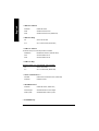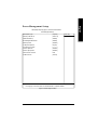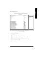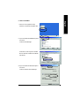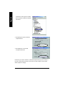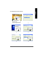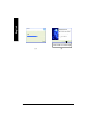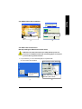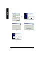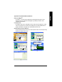
1
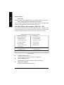
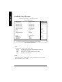
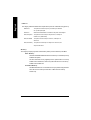
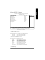
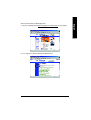
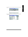
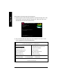
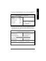
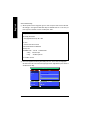
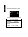
GA-8IEX Series User’s Manual
(Technical Reference)
Rev.1201
English
Table of Content
BIOS Setup ............................................................................................................... 3
The Main Menu (For example: BIOS Ver. :F5) ....................................................... 4
Standard CMOS Features .................................................................................... 6
Advanced BIOS Features ..................................................................................... 9
Integrated Peripherals ....................................................................................... 11
Power Management Setup ................................................................................. 17
PnP/PCI Configurations ..................................................................................... 20
PC Health Status ............................................................................................... 21
Frequency/Voltage Control ................................................................................. 23
Top Performance ............................................................................................... 25
Select Language ................................................................................................ 26
Load Fail-Safe Defaults ...................................................................................... 27
Load Optimized Defaults .................................................................................... 28
Set Supervisor/User Password ........................................................................... 29
Save & Exit Setup .............................................................................................. 30
Exit Without Saving ........................................................................................... 31
Block Diagram ......................................................................................................... 32
BIOS Flash Procedure ............................................................................................. 33
@ BIOS Introduction ................................................................................................ 54
Easy TuneTM 4Introduction ........................................................................................ 55
Four speaker & SPDIF Introduction .......................................................................... 56
Driver Installing ........................................................................................................ 63
Acronyms ................................................................................................................ 78
Technical Support / RMA Sheet ................................................................................ 80
GA-8IEX Series Motherboard
-2 -
BIOS Setup is an overview of the BIOS Setup Program. The program that allows users to modify
the basic system configuration. This type of information is stored in battery-backed CMOS RAM so
that it retains the Setup information when the power is turned off.
ENTERING SETUP
After power on the computer, pressing <Del> immediately during POST (Power On Self Test) it will allow you to
enter standard BIOS CMOS SETUP.
If you require more advanced BIOS settings, please go to “Advanced BIOS”setting menu.To enter
Advanced BIOS setting menu, press “Ctrl+F1”key on the BIOS screen.
CONTROL KEYS
<á>
<â>
Move to previous item
Move to next item
<ß>
Move to the item in the left hand
<à>
Move to the item in the right hand
<Esc>
Main Menu - Quit and not save changes into CMOS Status Page Setup Menu and
Option Page Setup Menu - Exit current page and return to Main Menu
<+/PgUp>
Increase the numeric value or make changes
<-/PgDn>
Decrease the numeric value or make changes
<F1>
General help, only for Status Page Setup Menu and Option Page Setup Menu
<F2>
Item help
<F3>
Reserved
<F4>
Reserved
<F5>
Restore the previous CMOS value from CMOS, only for Option Page Setup Menu
<F6>
Load the default CMOS value from BIOS default table, only for Option Page Setup
Menu
<F7>
Load the Setup Defaults
<F8>
Dual BIOS/Q-Flash
<F9>
Reserved
<F10>
Save all the CMOS changes, only for Main Menu
-3 -
Technical Reference
English
BIOS Setup
English
GETTING HELP
Main Menu
The on-line description of the highlighted setup function is displayed at the bottom of the screen.
Status Page Setup Menu / Option P age Setup Menu
Press F1 to pop up a small help window that describes the appropriate keys to use and the possible
selections for the highlighted item. To exit the Help Window press <Esc>.
The Main Menu (For example: BIOS Ver. : F5)
Once you enter Award BIOS CMOS Setup Utility, the Main Menu (Figure 1) will appear on the
screen. The Main Menu allows you to select from eight setup functions and two exit choices. Use
arrow keys to select among the items and press <Enter> to accept or enter the sub-menu.
CMOS Setup Utility-Copyright (C) 1984-2002 Award Software
}Standard CMOS Features
Select Language
}Advanced BIOS Features
Load Fail-Safe Defaults
}Integrated Peripherals
Load Optimized Defaults
}Power Management Setup
Set Supervisor Password
}PnP/PCI Configurations
Set User Password
}PC Health Status
Save & Exit Setup
}Frequency/Voltage Control
Exit Without Saving
Top Performance
ESC:Quit
F3:Change Language
F8:Dual BIOS /Q-Flash
F10:Save & Exit Setup
Time, Date, Hard Disk Type...
Figure 1: Main Menu
l
Standard CMOS Features
This setup page includes all the items in standard compatible BIOS.
l
Advanced BIOS Features
This setup page includes all the items of Award special enhanced features.
l
Integrated Peripherals
This setup page includes all onboard peripherals.
GA-8IEX Series Motherboard
-4 -
Power Management Setup
This setup page includes all the items of Green function features.
l
PnP/PCI Configurations
l
PC Health Status
This setup page includes all the configurations of PCI & PnP ISA resources.
This setup page is the System auto detect Temperature, voltage, fan, speed.
l
Frequency/Voltage Control
l
Top Performance
This setup page is control CPU’s clock and frequency ratio.
Top Performance Defaults indicates the value of the system parameters which the system
would be in best performance configuration.
l
Select Language
This setup page is select multi language.
l
Load Fail-Safe Defaults
Fail-Safe Defaults indicates the value of the system parameters which the system would
be in safe configuration.
l
Load Optimized Defaults
Optimized Defaults indicates the value of the system parameters which the system would
be in better performance configuration.
l
Load Top Performance Defaults
Top Performance Defaults indicates the value of the system parameters which the system
would be in best performance configuration.
l
Set Supervisor password
Change, set, or disable password. It allows you to limit access to the system and Setup,
or just to Setup.
l
Set User password
Change, set, or disable password. It allows you to limit access to the system.
l
Save & Exit Setup
Save CMOS value settings to CMOS and exit setup.
l
Exit Without Saving
Abandon all CMOS value changes and exit setup.
-5 -
Technical Reference
English
l
English
Standard CMOS Features
CMOS Setup Utility-Copyright (C) 1984-2002 Award Software
Standard CMOS Features
Date (mm:dd:yy)
Thu, Feb 21 2002
Item Help
Time(hh:mm:ss)
22:31:24
Menu Level u
}IDE Primary Master
[Press Enter None]
Change the day, month,
}IDE Primary Slave
[Press Enter None]
year
}IDE Secondary Master
[Press Enter None]
<Week>
}IDE Secondary Slave
[Press Enter None]
Sun. to S at.
Drive A
[1.44M, 3.5”]
<Month>
Drive B
[None]
Jan. to Dec.
Floppy 3 Mode Support
[Disabled]
<Day>
Halt On
[All, But Keyboard]
in the month.)
Base Memory
640K
<year>
Extended Memory
130048K
1999 to 2098
Total Memory
131072K
1 to 31(or maximun allow ed
higf: Move Enter:Select +/-/PU/PD:Value F10:Save ESC:Exit F1:General Help
F3:Language F5:Previous Values F6:Fail-Safe Defaults F7:Optimized Defaults
Figure 2: Standard CMOS Features
FDate
The date format is <week>, <month>, <day>, <year>.
8Week
8Month
The week, from Sun to Sat, determined by the BIOS and is display only
The month, Jan. Through Dec.
8Day
8Year
The day, from 1 to 31 (or the maximum allowed in the month)
The year, from 1999 through 2098
FTime
The times format in <hour> <minute> <second>. The time is calculated base on the 24-hour militarytime clock. For example, 1 p.m. is 13:00:00.
GA-8IEX Series Motherboard
-6 -
The category identifies the types of hard disk from drive C to F that has been installed in the
computer. There are two types: auto type, and manual type. Manual type is user-definable; Auto
type which will automatically detect HDD type.
Note that the specifications of your drive must match with the drive table. The hard disk will not work
properly if you enter improper information for this category.
If you select User Type, related information will be asked to enter to the following items. Enter the
information directly from the keyboard and press <Enter>. Such information should be provided in
the documentation form your hard disk vendor or the system manufacturer.
8Capacity:
The hard disk size. The unit is Mega Bytes.
8Access Mode:
8Cylinder:
The options are: Auto / Large / LBA / Normal.
The cylinder number of hard disk.
8Head
The read / Write head number of hard disk.
8Precomp
8Landing Zone
The cyliner number at which the disk driver changes the write current.
The cylinder number that the disk driver heads(read/write) are seated when the
disk drive is parked.
8SECTORS
The sector number of each track define on the hard disk.
If a hard disk has not been installed select NONE and press <Enter>.
FDrive A / Drive B
The category identifies the types of floppy disk drive A or drive B that has been installed in the
computer.
8None
No floppy drive installed
8360K, 5.25 “.
81.2M, 5.25”.
5.25 inch PC-type standard drive; 360K byte capacity.
5.25 inch AT-type high-density drive; 1.2M byte capacity
8720K, 3.5 “.
81.44M, 3.5 “.
3.5 inch double-sided drive; 720K byte capacity
3.5 inch double-sided drive; 1.44M byte capacity.
82.88M, 3.5 “.
3.5 inch double-sided drive; 2.88M byte capacity.
(3.5 inch when 3 Mode is Enabled).
FFloppy 3 Mode Support (for Japan Area)
8Disabled
Normal Floppy Drive. (Default value)
8Drive A
Enabled 3 mode function of Drive A.
8Drive B
Enabled 3 mode function of Drive B.
8Both
Drive A & B are 3 mode Floppy Drives.
-7 -
Technical Reference
English
FIDE Primary Master, Slave / Secondary Master, Slave
English
FHalt on
The category determines whether the computer will stop if an error is detected during power up.
8NO Errors
The system boot will not stop for any error that may be detected
and you will be prompted.
8All Errors
Whenever the BIOS detects a non-fatal error the system will be stopped.
8All, But Keyboar
The system boot will not stop for a keyboard error; it will stop for
all other errors. (Default value)
8All, But Diskette
The system boot will not stop for a disk error; it will stop for all
other errors.
8All, But Disk/Key
The system boot will not stop for a keyboard or disk error; it will
stop for all other errors.
Memory
The category is display-only which is determined by POST (Power On Self Test) of the BIOS.
Base Memory
The POST of the BIOS will determine the amount of base (or conventional) memory
installed in the system.
The value of the base memory is typically 512 K for systems with 512 K memory
installed on the motherboard, or 640 K for systems with 640 K or more memory
installed on the motherboard.
Extended Memory
The BIOS determines how much extended memory is present during the POST.
This is the amount of memory located above 1 MB in the CPU’s memory
address map.
GA-8IEX Series Motherboard
-8 -
English
Advanced BIOS Features
CMOS Setup Utility-Copyright (C) 1984-2002 Award Software
Advanced BIOS Features
RAID/SCSIBootOrder**
[RAID,SCSI]
Item Help
First Boot Device
[Floppy]
Menu Level
Second Boot Device
[HDD-0]
Third Boot Device
[CDROM]
Boot Up Floppy Seek
[Disabled]
DRAM Data Integrity Mode
Non-ECC
Init Display First
[AGP]
higf: Move Enter:Select +/-/PU/PD:Value F10:Save ESC:Exit F1:General Help
F3:Language F5:Previous Values F6:Fail-Safe Defaults F7:Optimized Defaults
Figure 3: Advanced BIOS Features
FRAID / SCSI Boot Order**
M This feature allows you to select the boot order RAID or SCSI device.
8RAID,SCSI
Select your boot device priority by RAID.
8SCSI,RAID
Select your boot device priority by SCSI.
FFirst / Second / Third Boot device
M This feature allows you to select the boot device priority.
8Floppy
Select your boot device priority by Floppy.
8LS120
Select your boot device priority by LS120.
8HDD-0~3
Select your boot device priority by HDD-0~3.
8SCSI
Select your boot device priority by SCSI.
8CDROM
Select your boot device priority by CDROM.
8LAN
Select your boot device priority by LAN.
8USB-CDROM
Select your boot device priority by USB-CDROM.
** For GA-8IEXP Only.
-9 -
Technical Reference
English
8USB-ZIP
Select your boot device priority by USB-ZIP.
8USB-FDD
Select your boot device priority by USB-FDD.
8USB-HDD
Select your boot device priority by USB-HDD.
8ZIP
Select your boot device priority by ZIP.
8Disabled
Disabled this function.
FBoot Up Floppy Seek
MDuring POST, BIOS will determine the floppy disk drive installed is 40 or 80 tracks. 360 K type is 40
tracks 720 K, 1.2 M and 1.44 M are all 80 tracks.
8Enabled
BIOS searches for floppy disk drive to determine it is 40 or 80 tracks. Note
that BIOS can not tell from 720 K, 1.2 M or 1.44 M drive type as they are
all 80tracks.
8Disabled
BIOS will not search for the type of floppy disk drive by track number. Note
that there will not be any warning message if the drive installed is 360 K.
(Default value)
FDRAM Data Integrity Mode
MThis feature allows you to set the DRAM data Integrity Mode
8Non-ECC
Set the DRAM data Integrity Mode is Non-ECC (Default)
8ECC
Set the DRAM data Integrity Mode is ECC.
FInit Display First
M This feature allows you to select the first initation of the monitor display from which card, when
you install an AGP VGA card and a PCI VGA card on board.
8PCI
Set Init Display First to PCI Slot.
8AGP
Set Init Display First to AGP. (Default value)
GA-8IEX Series Motherboard
- 10 -
English
Integrated Peripherals
CMOS Setup Utility-Copyright (C) 1984-2002 Award Software
Integrated Peripherals
On-Chip Primary PCI IDE
[Enabled]
Item Help
On-Chip Secondary PCI IDE
[Enabled]
Menu Level
IDE1 Conductor Cable
[Auto]
IDE2 Conductor Cable
[Auto]
USB Controller
[Enabled]
USB Keyboard Support
[Disabled]
USB Mouse Support
[Disabled]
Onboard H/W 1394**
[Enabled]
Onboard H/W Sound
[Enabled]
Onboard ATA/RAID Device **
[Enabled]
RAID Controller Function**
[ATA]
Onboard LAN Controller
[Enabled]
Onboard LAN Boot ROM
[Disabled]
Onboard Serial Port 1
[3F8/IRQ4]
Onboard Serial Port 2
[2F8/IRQ3]
UART Mode Select
[Normal]
øUR2 Duplex Mode
Half
Onboard Parallel Port
[378/IRQ7]
Parallel Port Mode
[SPP]
øECP Mode Use DMA
3
Game Port Address
[201]
Mdi Port Address
[330]
Midi Port IRQ
[10]
CIR Port Address
[Disabled]
øCIR Port IRQ
11
Smart Card Interface**
[Enabled]
MS/SD Interface**
[Disabled]
higf: Move Enter:Select +/-/PU/PD:Value F10:Save ESC:Exit F1:General Help
F3:Language F5:Previous Values F6:Fail-Safe Defaults F7:Optimized Defaults
Figure 4: Integrated Peripherals
** For GA-8IEXP Only.
- 11 -
Technical Reference
English
FOn-Chip P rimary PCI IDE
MWhen enabled, allows you to use the onboard primary PCI IDE. If a hard disk controller card is
used, set at Disabled.
8Enabled
Enable onboard 1st channel IDE port. (Default value)
8Disabled
Disable onboard 1st channel IDE port.
FOn-Chip Secondary PCI IDE
MWhen enabled, allows you to use the onboard secondary PCI IDE. If a hard disk controller card
is used, set at Disabled.
8Enabled
Enable onboard 2nd channel IDE port. (Default value)
8Disabled
Disable onboard 2nd channel IDE port.
FIDE1 Conductor Cable
8Auto
Will be automatically detected by BIOS (Default Value)
8ATA66/100 Set IDE1 Conductor Cable to ATA66/100 (Please make sure your IDE device and cable
is compatible with ATA66/100)
8ATA33
Set IDE1 Conductor Cable to ATA33 (Please make sure your IDE device and cable is
compatible with ATA33)
FIDE2 Conductor Cable
8Auto
Will be automatically detected by BIOS (Default Value)
8ATA66/100 Set IDE2 Conductor Cable to ATA66/100 (Please make sure your IDE device and cable
is compatible with ATA66/100)
8ATA33
Set IDE2 Conductor Cable to ATA33 (Please make sure your IDE device and cable is
compatible with ATA33).
FUSB Controller
MDisable this option if you are not using the onboard USB feature.
8Enabled
Enabled USB Controller. (Default value)
8Disabled
Disabled USB Controller.
GA-8IEX Series Motherboard
- 12 -
English
FUSB Keyboard Support
MWhen a USB keyboard is installed, please set at Enabled.
8Enabled
Enabled USB Keyboard Support.
8Disabled
Disabled USB Keyboard Support. (Default value)
FUSB Mouse Support
8Enabled
Enabled USB Mouse Support.
8Disabled
Disabled USB Mouse Support. (Default value)
FOnboard H/W 1394**
8Enable
Enabled onboard IEEE 1394 function.(Default value)
8Disable
Disabled onboard this function.
FOnboard H/W Sound
8Enable
Enabled onboard sound function.(Default value)
8Disable
Disabled onboard sound function.
FOnboard ATA/RAID Device**
M If you don't set any HDD Devi ce in IDE3 or 4 but enable the function, the normal
message 'MBUltra133 BIOS is not installed becasue there are no drives attached' will come
out.'
Ignore this message or set the option disable to make the message disappear.
8Enable
Enabled onboard ATA/RAID function.(Default value)
8Disable
Disabled onboard sound function.
FRAID Controller Function**
8ATA
Enabled ATA function.(Default value)
8RAID
Enabled RAID function.
FOnboard LAN Controller
8Enable
Enabled onboard LAN function.(Default value)
* For GA-8IEXP Only.
- 13 -
.
Technical Reference
English
8Disable
Disable onboard LAN function.
FOnboard LAN Boot ROM
MDecide whether to invoke the boot ROM of the onboard LAN chip.
8Enable
Enable onboard LAN boot ROM function.(Default value)
8Disable
Disable this function.
FOnboard Serial Port 1
8Auto
BIOS will automatically setup the port 1 address.
83F8/IRQ4
Enable onboard Serial port 1 and address is 3F8. (Default value)
82F8/IRQ3
Enable onboard Serial port 1 and address is 2F8.
83E8/IRQ4
Enable onboard Serial port 1 and address is 3E8.
82E8/IRQ3
Enable onboard Serial port 1 and address is 2E8.
8Disabled
Disable onboard Serial port 1.
FOnboard Serial Port 2
8Auto
BIOS will automatically setup the port 2 address.
83F8/IRQ4
Enable onboard Serial port 2 and address is 3F8.
82F8/IRQ3
Enable onboard Serial port 2 and address is 2F8. (Default Value)
83E8/IRQ4
Enable onboard Serial port 2 and address is 3E8.
82E8/IRQ3
Enable onboard Serial port 2 and address is 2E8.
8Disabled
Disable onboard Serial port 2.
FUART Mode Select
MThis feature allows you to determine which Infra Red(IR) function of Onboard I/O chip)
8ASKIR
Using as IR and set to ASKIR Mode.
8IrDA
Using as IR and set to IrDA Mode.
8Normal
Using as standard serial port. (Default Value)
8SCR
Using as smart card Interface.
GA-8IEX Series Motherboard
- 14 -
English
FUR2 Duplex Mode
MThis feature allows you to select the IR modes.
8Half
IR Function Duplex Half. (Default Value)
8Full
IR Function Duplex Full.
FOnBoard Parallel port
MThis feature allows you to select from a given set of parameters if the parallel port uses the
onboard I/O controller.
8378/IRQ7
Enable On Board LPT port and address is 378.(Default Value)
8278/IRQ5
Enable On Board LPT port and address is 278.
83BC/IRQ7
Enable On Board LPT port and address is 3BC.
FParallel Port Mode
MThis feature allows you to connect with an advanced print via the port mode it supports.
8SPP
Using Parallel port as Standard Parallel Port using IRQ7. (Default Value)
8EPP
Using Parallel port as Enhanced Parallel Port IRQ5.
8ECP
Using Parallel port as Extended Capabilities Port using IRQ7.
8ECP+EPP
Using Parallel port as ECP & EPP mode.
FECP Mode Use DMA
83
Set ECP mode use DMA 3. (Default value)
81
Set ECP mode use DMA 1.
FGame Port Address
8Disabled
Disabled this function.
8201
Set Game Port Address to 201. (Default Value)
8209
Set Game Port Address to 209.
- 15 -
Technical Reference
English
FMidi Port Address
8Disabled
Disabled this function.
8300
Set Midi Port Address to 300.
8330
Set Midi Port Address to 300.(Default Value)
FMidi Port IRQ
85
Set 5 for Midi Port IRQ.
810
Set 11 for Midi Port IRQ. (Default Value)
FCIR Port Address
This feature allows you to select CIR port address or disable it.
8Disabled
Disabled this function. (Default Value)
8310
Set CIR Port Address to 310.
8320
Set CIR Port Address to 320.
FCIR Port IRQ
This feature allows you to select CIR IRQ , if CIR is enabled.
85
Set 5 for CIR Port IRQ.
811
Set 11 for CIR Port IRQ. (Default Value)
FSmart Card Interface**
8Enabled
Enabled smatr card interface function. (Default value)
8Disabled
Disable this function.
FMS/SD Interface**
8Disabled
Disabled this function. (Default Value)
8Secure Digital
Set MS/SD Interface to “Secure Digital”.
8Memory Stick
Set MS/SD Interface to “Memory Stick”.
** For GA-8IEXP Only.
GA-8IEX Series Motherboard
- 16 -
English
Power Management Setup
CMOS Setup Utility-Copyright (C) 1984-2002 Award Software
Power Management Setup
ACPI Suspend Type
[S1(POS)]
Item Help
Soft-Off by PWR-BTTN
[Instant-off]
Menu Level
PME Event Wake Up
[Enabled]
ModemRingOn/WakeOnLAN
[Enabled]
Resume by Alarm
[Disabled]
ø Date(of Month) Alarm
Everyday
ø Time(hh:mm:ss) Alarm
0: 0: 0
Power On By Mouse
[Disabled]
Power On By Keyboard
[Disabled]
øKB Power On Password
Enter
AC Back Function
[Soft-Off]
higf: Move Enter:Select +/-/PU/PD:Value F10:Save ESC:Exit F1:General Help
F3:Language F5:Previous Values F6:Fail-Safe Defaults F7:Optimized Defaults
Figure 5: Power Management Setup
- 17 -
Technical Reference
English
FACPI Suspend Type
8S1/POS
Set ACPI Suspend Type to S1/POS (Power On Suspend). (Default value)
8S3/STR
Set ACPI Suspend Type to S3/STR (Suspend To RAM).
FSoft-off by PWR-BTTN
8Instant-off
Press power button then Power off instantly. (Default value)
8Delay 4 Sec.
Press power button 4 sec to Power off. Enter suspend if button is pressed less
than 4 sec.
FPME Event Wake up
MWhen set at Enabled, any PCI-PM event awakes the system from a PCI-PM controlled
state.
M This feature requires an ATX power supply that provides at least 1A on the +5VSB
lead.
8Disabled
Disabled PME Event Wake up function.
8Enabled
Enabled PME Event Wake up function. (Default Value)
FModem Ring On/ WakeOnLAN (When AC Back Function is set to [Soft-Off])
M You can enable wake on LAN feature by the "ModemRingOn/WakeOnLAN" or "PME Event Wake
up" when the M/B has "WOL" onboard connector. Only enabled the feature by "PME Event Wake
up".
M An incoming call via modem awakes the system from its soft-off mode.
M When set at Enabled, an input signal comes from the other client/server on the LAN awaks the
system from a soft off state if connected over LAN.
8Disabled
Disabled Modem Ring On / Wake On LAN function.
8Enabled
Enabled Modem Ring On / Wake On LAN function. (Default Value)
FResume by Alarm
You can set "Resume by Alarm" item to enabled and key in Data/time to power on system.
8Disabled
Disable this function. (Default Value)
8Enabled
Enable alarm function to POWER ON system.
If RTC Alarm Lead To Power On is Enabled.
Date ( of Month) Alarm :
Everyday, 1~31
Time ( hh: mm: ss) Alarm :
(0~23) : (0~59) : (0~59)
GA-8IEX Series Motherboard
- 18 -
8Disabled
English
FPower On By Mouse
Disabled this function. (Default value)
8Mouse Click Set mouse double click to power on system.
F Power On By Keyboard
This feature allows you to set the method for powering-on the system.
The option “Password“allows you to set up to 5 alphanumeric characters to power-on the system.
The option “Any Key”allows you to touch the keyboard to power on the system.
The option “Keyboard 98”allows you to use the standard keyboard 98 to power on the system.
8Password
Enter from 1 to 5 characters to set the Keyboard Power On Password.
8Disabled
Disabled this function. (Default value)
8Keyboard 98
If your keyboard have “POWER Key”button, you can press the key to
power on your system.
FKB Power ON Password
8Enter
Input password (from 1 to 5 characters) and press Enter to set the Key
board Power On Password..
FAC Back Function
8Memory
System power on depends on the status before AC lost.
8Soft-Off
Always in Off state when AC back. (Default value)
8Full-On
Always power on the system when AC back.
- 19 -
Technical Reference
English
PnP/PCI Configurations
CMOS Setup Utility-Copyright (C) 1984-2002 Award Software
PnP/PCI Configurations
PCI1/PCI5 IRQ Assignment
[Auto]
Item Help
PCI2 /PCI6 IRQ Assignment
[Auto]
Menu Level
PCI3 IRQ Assignment
[Auto]
PCI4 IRQ Assignment
[Auto]
higf: Move Enter:Select +/-/PU/PD:Value F10:Save ESC:Exit F1:General Help
F3:Language F5:Previous Values F6:Fail-Safe Defaults F7:Optimized Defaults
Figure 6: PnP/PCI Configurations
FPCI1/P CI5 IRQ Assignment
8Auto
Auto assign IRQ to PCI 1/ PCI 5. (Default value)
83,4,5,7,9.,10,11,12,15
Set 3,4,5,7,9,10,11,12,15 to PCI1/ PCI5.
FPCI2/P CI6 IRQ Assignment
8Auto
Auto assign IRQ to PCI 2/ PCI 6. (Default value)
83,4,5,7,9.,10,11,12,15
Set 3,4,5,7,9,10,11,12,15 to PCI2/ PCI6.
FPCI3 IRQ Assignment
8Auto
Auto assign IRQ to PCI 3. (Default value)
83,4,5,7,9.,10,11,12,15
Set 3,4,5,7,9,10,11,12,15 to PCI3.
FPCI4 IRQ Assignment
8Auto
Auto assign IRQ to PCI 4. (Default value)
83,4,5,7,9.,10,11,12,15
Set 3,4,5,7,9,10,11,12,15 to PCI4.
GA-8IEX Series Motherboard
- 20 -
English
PC Health Status
CMOS Setup Utility-Copyright (C) 1984-2002 Award Software
PC Health Status
Reset Case Open Status
[Disabled]
Case Opened
No
VCORE
1.746V
VCC18
1.792V
+3.3V
3.296V
+ 5V
5.080 V
+12V
11.904V
Current CPU Temperature
39°C
Current CPU FAN Speed
4821 RPM
Current POWER FAN speed
0 RPM
Current SYSTEM FAN speed
0 RPM
CPU Warning Temperature
[Disabled]
CPU FAN Fail Warning
[Disabled]
POWER FAN Fail Warning
[Disabled]
SYSTEM FAN Fail Warning
[Disabled]
Item Help
Menu Level
higf: Move Enter:Select +/-/PU/PD:Value F10:Save ESC:Exit F1:General Help
F3:Language F5:Previous Values F6:Fail-Safe Defaults F7:Optimized Defaults
Figure7: PC Health Status
CReset Case Open Status
CCase Opened
If the case is closed, "Case Opened" will show "No".
If the case have been opened, "Case Opened" will show "Yes".
If you want to reset "Case Opened" value, set "Reset Case Open Status" to
"Enabled" and save CMOS, your computer will restart.
FCurrent Voltage (V) VCORE /VCC18/ +3.3V/ +5V / +12V
Detect system’s voltage status automatically.
- 21 -
Technical Reference
English
FCurrent CPU Temperature (°C)
Detect CPU Temp. automatically.
FCurrent CPU FAN / POWER / SYSTEM FAN Speed (RPM)
Detect Fan speed status automatically.
FCPU Warning Temperature
860°C / 140°F
Monitor CPU Temp. at 60°C / 140°F.
870°C / 158°F
Monitor CPU Temp. at 70°C / 158°F.
880°C / 176°F
Monitor CPU Temp. at 80°C / 176°F.
890°C / 194°F
Monitor CPU Temp. at 90°C / 194°F.
8Disabled
Don’tmonitor current temperature.(Default value)
FFan Fail Warning ( CP U / POWER / SYSTEM)
8Disabled
Fan Fail Alarm Function Disabled. (Default value)
8Enabled
Fan Fail Alarm Function Enabled.
GA-8IEX Series Motherboard
- 22 -
English
Frequency/Voltage Control
CMOS Setup Utility-Copyright (C) 1984-2002 Award Software
Frequency/Voltage Control
CPU Clock Ratio
[ 15X]
Item Help
CPU Host Clock Control
[Disable]
Menu Level
øCPU Host Frequency(MHz)
100
øFixed PCI/AGP Frequency
33/66
Host/DRAM Clock ratio
[Auto]
MemoryFrequency(MHz)
266
PCI/AGP Frequency(MHz)
33/66
DIMM OverVoltage Control
[Normal]
AGP OverVoltage Control
[Normal]
CPU Voltage Control
[Normal]
Normal CPU Vcore
1.75V
higf: Move Enter:Select +/-/PU/PD:Value F10:Save ESC:Exit F1:General Help
F3:Language F5:Previous Values F6:Fail-Safe Defaults F7:Optimized Defaults
Figure 8: Frequency/Voltage Control
øThose items will be available when "CPU Host Clock Control" is set to Enabled.
FCPU Clock Ratio
Set CPU Ratio if CPU Ratio is unlocked.
810X~ 24X
It’s depends on CPU Clock Ratio.
FCPU Host Clock Control
Note: If system hangs up before enter CMOS setup utility, wait for 20 sec for times out reboot . When
time out occur, system will reset and run at CPU default Host clock at next boot.
8Disable
Disable CPU Host Clock Control.(Default value)
8Enable
Enable CPU Host Clock Control.
FCPU Host Frequency (MHz)
8100MHz ~ 350MHzSet CPU Host Clock from 100MHz to 350MHz.
- 23 -
Technical Reference
English
FFixed PCI/AGP Frequency
8You can choose those mode to adjust PCI/AGP frequency. (Select PCI/AGP frequency asynchronous
with CPU frequency).
FHost/DRAM Clock Ratio
(Warning: wrong frequency may make system can’t boot, clear CMOS to overcome wrong frequency
issue)
82.0
Memory Frequency = Host clock X 2.0.
82.66
Memory Frequency = Host clock X 2.66.
8Auto
Set Memory frequency by DRAM SPD data. (Default value)
FMemory Frequency(Mhz)
8The values depend on CPU Host Frequency(Mhz) .
F PCI/AGP Frequency(Mhz)
8Setup PCI/AGP frequency by adjusting CPU Host Frequency or Fixed PCI/AGP Frequency item.
FDIMM OverVoltage Control
8Normal
8+0.1V~+.03V
The default DIMM voltage. (Default value)
Set DIMM voltage from 2.6V~2.8V.
FAGP OverVoltage Control
8Normal
Auto detect AGP voltage. (Default value)
8+0.1V~+.03V
Set AGP voltage from 1.6V~1.8V.
FCPU OverVoltage Control
8Normal
Auto detect CPU voltage. (Default value)
81.100V~1.850V Set CPU voltage from 1.100V~1.850V.
FNormal CPU Vcore 1.750V
GA-8IEX Series Motherboard
- 24 -
English
Top Performance
CMOS Setup Utility-Copyright (C) 1984-2002 Award Software
}Standard CMOS Features
Select Language
}Advanced BIOS Features
Load Fail-Safe Defaults
}Integrated Peripherals
Load Optimized Defaults
}Power Management Setup
Load Top Performance Defaults
}PnP/PCI Configurations
Set Supervisor Password
Disabled................... [ n
Enabled...................[
}PC Health Status
]
]
Set User Password
}Frequency/Voltage Control
Save & Exit Setup
Top Performance
hi: Move
ESC:Quit
ESC: Abort
F8:Dual BIOS /Q-Flash
Exit Without Saving
ENTER: Accept
F3:Change Language
F10:Save & Exit Setup
Figure 9: Top Performance
Top Performance
If you wish to maximize the performance of your system, set "Top Performance" as "Enabled".
8Disabled
Disable this function. (Default Value)
8Enabled
Enable Top Performance function.
- 25 -
Technical Reference
English
Select Language
CMOS Setup Utility-Copyright (C) 1984-2002 Award Software
}Standard CMOS Features
Select Language
}Advanced BIOS Features
Load Fail-Safe Defaults
}Integrated Peripherals
Load Optimized Defaults
}Power Management Setup
Set Supervisor Password
}PnP/PCI Configurations
Set User Password
}PC Health Status
Save & Exit Setup
}Frequency/Voltage Control
Exit Without Saving
u
Top Performance
ESC:Quit
F3:Change Language
F8:Dual BIOS /Q-Flash
F10:Save & Exit Setup
Figure 10:Select Language
Select Language
Multi Language is supports 7 languages. There are English, Japanese, French, Spanish,
Germany, Simplified Chinese, Traditional Chinese.
GA-8IEX Series Motherboard
- 26 -
CMOS Setup Utility-Copyright (C) 1984-2002 Award Software
}Standard CMOS Features
Select Language
}Advanced BIOS Features
Load Fail-Safe Defaults
}Integrated Peripherals
Load Optimized Defaults
}Power Management Setup
Set Supervisor Password
}PnP/PCI Configurations
Set User Password
}PC Health Status
Save & Exit Setup
Load
Fail-Safe
Defaults?Exit
(Y/N)?N
Figure 11: Load
Fail-Safe
Defaults
}Frequency/Voltage
Control
Without Saving
Top Performance
ESC:Quit
F3:Change Language
F8:Dual BIOS /Q-Flash
F10:Save & Exit Setup
Load Fail-Safe Defaults
Figure 11: Load Fail-Safe Defaults
FLoad Fail-Safe Defaults
Fail-Safe defaults contain the most appropriate values of the system parameters that allow
minimum system performance.
- 27 -
Technical Reference
English
Load Fail-Safe Defaults
English
Load Optimized Defaults
CMOS Setup Utility-Copyright (C) 1984-2002 Award Software
}Standard CMOS Features
Select Language
}Advanced BIOS Features
Load Fail-Safe Defaults
}Integrated Peripherals
Load Optimized Defaults
}Power Management Setup
Set Supervisor Password
}PnP/PCI Configurations
Set User Password
Load Optimized Defaults?
(Y/N)?N
Save & Exit Setup
}PC HealthFigure
Status11: Load Fail-Safe Defaults
}Frequency/Voltage Control
Exit Without Saving
Top Performance
ESC:Quit
F3:Change Language
F8:Dual BIOS /Q-Flash
F10:Save & Exit Setup
Load Optimized Defaults
Figure 12: Load Optimized Defaults
FLoad Optimized Defaults
Selecting this field loads the factory defaults for BIOS and Chipset Features which the
system automatically detects.
GA-8IEX Series Motherboard
- 28 -
English
Set Supervisor/User Password
CMOS Setup Utility-Copyright (C) 1984-2002 Award Software
}Standard CMOS Features
Select Language
}Advanced BIOS Features
Load Fail-Safe Defaults
}Integrated Peripherals
Load Optimized Defaults
}Power Management Setup
Set Supervisor Password
}PnP/PCI Configurations
Set User Password
}PC Health StatusEnter Password:
Figure 11: Load Fail-Safe Defaults
}Frequency/Voltage Control
Save & Exit Setup
Exit Without Saving
Top Performance
ESC:Quit
F3:Change Language
F8:Dual BIOS /Q-Flash
F10:Save & Exit Setup
Change/Set/Disable Password
Figure 13: Password Setting
When you select this function, the following message will appear at the center of the screen to
assist you in creating a password.
Type the password, up to eight characters, and press <Enter>. You will be asked to confirm the
password. Type the password again and press <Enter>. You may also press <Esc> to abort the
selection and not enter a password.
To disable password, just press <Enter> when you are prompted to enter password. A message
“PASSWORD DISABLED” will appear to confirm the password being disabled. Once the password
is disabled, the system will boot and you can enter Setup freely.
The BIOS Setup program allows you to specify two separate passwords: a SUPERVISOR PASSWORD and a USER PASSWORD. When disabled, anyone may access all BIOS Setup program
function. When enabled, the Supervisor password is required for entering the BIOS Setup program
and having full configuration fields, the User password is required to access only basic items.
If you select “System” at “Security Option” in Advance BIOS Features Menu, you will be prompted
for the password every time the system is rebooted or any time you try to enter Setup Menu.
If you select “Setup”at “Security Option”in Advance BIOS Features Menu, you will be prompted
only when you try to enter Setup.
- 29 -
Technical Reference
English
Save & Exit Setup
CMOS Setup Utility-Copyright (C) 1984-2002 Award Software
}Standard CMOS Features
Select Language
}Advanced BIOS Features
Load Fail-Safe Defaults
}Integrated Peripherals
Load Optimized Defaults
}Power Management Setup
Set Supervisor Password
}PnP/PCI Configurations
Set User Password
}PC Health Status
Save & Exit Setup
Save to
}Frequency/Voltage Control
CMOS and EXIT
(Y/N)?Saving
Y
Exit Without
Top Performance
ESC:Quit
F3:Change Language
F8:Dual BIOS /Q-Flash
F10:Save & Exit Setup
Save Data to CMOS
Figure 14: Save & Exit Setup
Type “Y”will quit the Setup Utility and save the user setup value to RTC CMOS.
Type “N”will return to Setup Utility.
GA-8IEX Series Motherboard
- 30 -
English
Exit Without Saving
CMOS Setup Utility-Copyright (C) 1984-2002 Award Software
}Standard CMOS Features
Select Language
}Advanced BIOS Features
Load Fail-Safe Defaults
}Integrated Peripherals
Load Optimized Defaults
}Power Management Setup
Set Supervisor Password
}PnP/PCI Configurations
Set User Password
}PC Health Status
Save & Exit Setup
Quit Without Saving (Y/N)? N
}Frequency/Voltage Control
Exit Without Saving
Top Performance
ESC:Quit
F3:Change Language
F8:Dual BIOS /Q-Flash
F10:Save & Exit Setup
Abandon all Data
Figure 15: Exit Without Saving
Type “Y”will quit the Setup Utility without saving to RTC CMOS.
Type “N”will return to Setup Utility.
- 31 -
Technical Reference
Pentium 4
CPU
CPUCLK6 (100/133MHz)
AGP 4X
System Bus 100MHz
AGPCLK
(66MHz)
100/133 MHz
Intel
82845E
6 PCI
DDR RAM
HCLK6 (100MHz)
MCHCLK (100/133MHz)
66 MHz
33 MHz
14.318 MHz
48 MHz
VT6306**
(1394)
82562ET
RJ45
Intel
ICH 4
PDC20276
LPC BUS (RAID133)
3 IEEE1394**
IDE3
IDE4
Game Port
Floppy
ITE8712
AC97
CODEC
Game Port
6 USB
Ports
ATA33/66/100
IDE Channels
24 MHz
PS/2
KB/Mouse
33 MHz
COM
Ports
PCICLK (33MHz)
USBCLK (48MHz)
14.318 MHz
33 MHz
LINE-OUT
W83L518D
LINE-IN
PCICLK
(33MHz)
LPT Port
AC97 Link
Creative
CT5880
MIC
English
Block Diagram
MS**
CLK
GEN
** For GA-8IEXP Only.
GA-8IEX Series Motherboard
- 32 -
SD**
SC
HCLK6 (100MHz)
CPUCLK6 (100/133MHz)
AGPCLK (66MHz)
MCHCLK (100/133mHz)
ICH3V66 (66MHz)
TM
Program to flash BIOS.
Method 1:
We use GA-7VTX motherboard and Flash841 BIOS flash utility as example.
Please flash the BIOS according to the following procedures if you are now under the DOS mode.
Flash BIOS Procedure:
STEP 1:
(1) Please make sure your system has installed the extraction utility such as winzip or pkunzip.
Firstly you have to install the extraction utility such as winzip or pkunzip for unzip the files.
Both of these utilities are available on many shareware download pages like http://www.
shareware.cnet.com
STEP 2: Make a DOS boot diskette. (See example: Windows 98 O.S.)
Beware: Windows ME/2000 are not allowed to make a DOS boot diskette.
(1) With an available floppy disk in the floppy drive. Please leave the diskette "UN-write
protected" type. Double click the "My Computer" icon from Desktop, then click "3.5 diskette
(A)" and right click to select "Format (M)"
- 33 -
Technical Reference
English
BIOS Flash Procedureyte @BIOS
English
(2) Select the "Quick (erase)" for Format Type, and pick both "Display summary when finished"
and "Copy system files", after that press "Start". That will format the floppy and transfer the
needed system files to it.
Beware: This procedure will erase all the prior data on that floppy, so please proceed
accordingly.
(3) After the floppy has been formatted completely, please press "Close".
GA-8IEX Series Motherboard
- 34 -
(1) Please go to Gigabyte website http://www.gigabyte.com.tw/index.html, and click "Support".
(2) From Support zone, click the "Motherboards BIOS & Drivers".
- 35 -
Technical Reference
English
STEP 3: Download BIOS and BIOS utility program.
English
(3) We use GA-7VTX motherboard as example. Please select GA-7VTX by Model or Chipset
optional menu to obtain BIOS flash files.
(4) Select an appropriate BIOS version (For example: F4), and click to download the file. It will
pop up a file download screen, then select the "Open this file from its current location" and
press "OK".
GA-8IEX Series Motherboard
- 36 -
files.
(6) Please extract the download files into the clean bootable floppy disk A mentioned in STEP 2,
and press "Extract".
- 37 -
Technical Reference
English
(5) At this time the screen shows the following picture, please click "Extract" button to unzip the
English
STEP 4: Make sure the system will boot from the floppy disk.
(1) Insert the floppy disk (contains bootable program and unzip file) into the floppy drive A. Then,
restart the system. The system will boot from the floppy disk. Please press <DEL> key to
enter BIOS setup main menu when system is boot up.
Amer ican R el ea se :0 9/16 /9 9
Meg atre nd s AMIBIOS (C ) 1 99 9 Amer ica n Me ga tr en d
7VTX F1
Che ck Syste m He alth OK
AMD -Athlo n(tm)Processor-900 MHz
Ch ecking NVR AM...
262144KB
Wa it...
Pre ss F1 to en ter D ual BIOS Utility. Pre ss ESC to q uit
Press a ny key to co ntiune
( C ) Amer ican Megatre nds In c.,
63-0001-001199-00101111-071595-VIA_K7-GA7VTX1-F
(2) Once you enter the BIOS setup utility, the main menu will appear on the screen. Use the
arrows to highlight the item "BIOS FEATURES SETUP".
AMIBIOS SIMPLE SETUP UTILITY - VERSION 1.24b
(C) 1999 American Megatrends, Inc. All Rights Reserved
STANDARD CMOS SETUP
INTEGRATED PERIPHERALS
BIOS FEATURES SETUP
HARDWARE MONITOR & MISC SETUP
CHIPSET FEATURES SETUP
SUPERVISOR PASSWORD
POWER MANAGEMENT SETUP
USER PASSWORD
PNP / PCI CONFIGURATION
IDE HDD AUTO DETECTION
LOAD BIOS DEFAULTS
SAVE & EXIT SETUP
LOAD SETUP DEFAULTS
EXIT WITHOUT SAVING
ESC: Quit
hifg : Select Item
F6: Load BIOS Defaults
(Shift)F2 : Change Color
F7: Load Setup Defaults
F10:Save & Exit
Time, Date , Hard Disk Type…
GA-8IEX Series Motherboard
- 38 -
F5: Old Values
"1st Boot Device", and then use the "Page Up" or "Page Down" keys to select "Floppy".
AMIBIOS SETUP - BIOS FEATURES SETUP
( C ) 2001 American Megatrends, Inc. All Rights Reserved
1st Boot Device
: Floppy
2nd Boot Device
: IDE-0
3rd Boot Device
: CDROM
S.M.A.R.T. for Hard Disks
: Disabled
BootUp Num-Lock
: On
ESC: Quit
hifg: Select Item
Floppy Drive Seek
: Disabled
F1 : Help
PU/PD/+/- : Modify
Password Check
: Setup
F5 : Old Values (Shift)F2: Color
F6 : Load BIOS Defaults
F7 : Load Setup Defaults
(4) Press "ESC" to go back to previous screen. Use the arrows to highlight the item "SAVE &
EXIT SETUP" then press "Enter". System will ask "SAVE to CMOS and EXIT (Y/N)?" Press
"Y" and "Enter" keys to confirm. Now the system will reboot automatically, the new BIOS
setting will be taken effect next boot-up.
AMIBIOS SIMPLE SETUP UTILITY - VERSION 1.24b
(C) 2001 American Megatrends, Inc. All Rights Reserved
STANDARD CMOS SETUP
INTEGRATED PERIPHERALS
BIOS FEATURES SETUP
HARDWARE MONITOR & MISC SETUP
CHIPSET FEATURES SETUP
SUPERVISOR PASSWORD
POWER MANAGEMENT SETUP
USER PASSWORD
PNP / PCI CONFIGURATION Save to
CMOS and EXIT
(Y/N)?
Y DETECTION
IDE HDD
AUTO
LOAD BIOS DEFAULTS
SAVE & EXIT SETUP
LOAD SETUP DEFAULTS
EXIT WITHOUT SAVING
ESC: Quit
hifg : Select Item
F6: Load BIOS Defaults
(Shift)F2 : Change Color
F7: Load Setup Defaults
F5: Old Values
F10:Save & Exit
Save Data to CMOS & Exit SETUP
- 39 -
Technical Reference
English
(3) Press "Enter" to enter "BIOS FEATURES SETUP" menu. Use the arrows to highlight the item
English
STEP 5: BIOS flashing.
(1) After the system boot from floppy disk, type "A:\> dir/w" and press "Enter" to check the entire
files in floppy A. Then type the "BIOS flash utility" and "BIOS file" after A:\>. In this case you
have to type "A:\> Flash841 7VTX.F4" and then press "Enter".
Starting Windows 98…
Microsoft(R) Windows98
© Copyright Microsoft Corp 1981-1999
A:\> dir/w
Volume in drive A has no label
Volume Serial Number is 16EB-353D
Directory of A:\
COMMAND.COM 7VTX.F4 FLASH841.EXE
3 file(s)
838,954 bytes
0 dir(s)
324,608 bytes free
A:\> Flash841 7VTX.F4
(2) Now screen appears the following Flash Utility main menu. Press "Enter", the highlighted
item will locate on the model name of the right-upper screen. Right after that, press "Enter" to
start BIOS Flash Utility.
GA-8IEX Series Motherboard
- 40 -
theprocedure, or press [ESC] to quit.
Beware: Please do not turn off the system while you are upgrading BIOS. It will render your
BIOS corrupted and system totally inoperative.
Are you sure to flash the BIOS?
[Enter] to continue Or [Esc] to cancel?
(4) The BIOS flash completed. Please press [ESC] to exit Flash Utility.
EXIT?
[Enter] to continue Or [Esc] to cancel?
- 41 -
Technical Reference
English
(3) It will pop up a screen and asks "Are you sure to flash the BIOS?" Press [Enter] to continue
English
STEP 6: Load BIOS defaults.
Normally the system redetects all devices after BIOS has been upgraded. Therefore, we
highly recommend reloading the BIOS defaults after BIOS has been upgraded. This
important step resets everything after the flash.
(1) Take out the floppy diskette from floppy drive, and then restart the system. The boot up
screen will indicate your motherboard model and current BIOS version.
Amer ican R el ea se :0 9/16 /9 9
Meg atre nd s AMIBIOS (C ) 1 99 9 Amer ica n Me ga tr en d
7VTX F4
Che ck Syste m He alth OK
AMD -Athlo n(tm)Processor-900 MHz
Ch ecking NVR AM...
262144KB
Wa it...
Pre ss F1 to en ter D ual BIOS Utility. Pre ss ESC to q uit
Press a ny key to co ntiune
( C ) Amer ican Megatre nds In c.,
63-0001-001199-00101111-071595-VIA_K7-GA7VTX1-F
(2) Don't forget to press <DEL> key to enter BIOS setup again when system is boot up. Use the
arrows to highlight the item "LOAD SETUP DEFAULTS" then press "Enter". System will ask
"Load Setup Defaults (Y/N)?" Press "Y" and "Enter" keys to confirm.
AMIBIOS SIMPLE SETUP UTILITY - VERSION 1.24b
(C) 2001 American Megatrends, Inc. All Rights Reserved
STANDARD CMOS SETUP
INTEGRATED PERIPHERALS
BIOS FEATURES SETUP
HARDWARE MONITOR & MISC SETUP
CHIPSET FEATURES SETUP
SUPERVISOR PASSWORD
POWER MANAGEMENT SETUP
USER PASSWORD
PNP / PCI CONFIGURATION Load Setup Defaults?
IDE(Y/N)?N
HDD AUTO DETECTION
LOAD BIOS DEFAULTS
SAVE & EXIT SETUP
LOAD SETUP DEFAULTS
EXIT WITHOUT SAVING
ESC: Quit
hifg : Select Item
F6: Load BIOS Defaults
(Shift)F2 : Change Color
F7: Load Setup Defaults
Load Setup Defaults
GA-8IEX Series Motherboard
- 42 -
F10:Save & Exit
F5: Old Values
ask "SAVE to CMOS and EXIT (Y/N)?" Press "Y" and "Enter" keys to confirm. Now the
system will reboot automatically, the new BIOS setting will be taken effect next boot-up.
AMIBIOS SIMPLE SETUP UTILITY - VERSION 1.24b
(C) 2001 American Megatrends, Inc. All Rights Reserved
STANDARD CMOS SETUP
INTEGRATED PERIPHERALS
BIOS FEATURES SETUP
HARDWARE MONITOR & MISC SETUP
CHIPSET FEATURES SETUP
SUPERVISOR PASSWORD
POWER MANAGEMENT SETUP
USER PASSWORD
PNP / PCI CONFIGURATION Save to
CMOS and EXIT
(Y/N)?
Y DETECTION
IDE HDD
AUTO
LOAD BIOS DEFAULTS
SAVE & EXIT SETUP
LOAD SETUP DEFAULTS
EXIT WITHOUT SAVING
ESC: Quit
hifg : Select Item
F6: Load BIOS Defaults
(Shift)F2 : Change Color
F7: Load Setup Defaults
F5: Old Values
F10:Save & Exit
Save Data to CMOS & Exit SETUP
(4) Congratulate you have accomplished the BIOS flash procedure.
- 43 -
Technical Reference
English
(3) Use the arrows to highlight the item "SAVE & EXIT SETUP" and press "Enter". System will
English
Method 3:
Dual BIOS / Q-Flash Introduction
A. What is Dual BIOS Technology?
Dual BIOS means that there are two system BIOS (ROM) on the motherboard, one is the
Main BIOS and the other is Backup BIOS. Under the normal circumstances, the system works on
the Main BIOS. If the Main BIOS is corrupted or damaged, the Backup BIOS can take over while
the system is powered on. This means that your PC will still be able to run stably as if nothing
has happened in your BIOS.
B. How to use Dual BIOS and Q-Flash Utility?
a. After power on the computer, pressing <Del> immediately during POST (Power On Self Test) it
will allow you to enter Award BIOS CMOS SETUP, then press <F8> to enter Flash utility.
CMOS Setup Utility-Copyright (C) 1984-2002 Award Software
}Standard CMOS Features
Select Language
}Advanced BIOS Features
Load Fail-Safe Defaults
}Integrated Peripherals
Load Optimized Defaults
}Power Management Setup
Set Supervisor Password
}PnP/PCI Configurations
Set User Password
}PC Health Status
Save & Exit Setup
}Frequency/Voltage Control
Top Performance
Exit Without Saving
Enter Dual BIOS / Q-Flash Utility (Y/N)? Y
ESC:Quit
F3:Change Language
F8:Dual BIOS /Q-Flash
F10:Save & Exit Setup
GA-8IEX Series Motherboard
- 44 -
English
b. Dual BIOS / Q-Flash Utility
Dual BIOS / Q-Flash Utility V845.4MF3
(C) 2001, GIGA-BYTE Technology Co., LTD.
Wide Range Protection
Halt On BIOS Defects
:Disabled
:Disabled
Auto Recovery
Boot From
BIOS Recovery
:Enabled
:Main BIOS
:Main to Backup
F3: Load Default
F7: Save And Restart
F8: Update BIOS from disk
F5:Start BIOS Recovery
F9:Exit Without Saving
F10:Recovery from Disk
Use <Space> key to toggle setup
c. Dual BIOS Item explanation:
Wide Range Protection: Disabled(Default), Enabled
Status 1:
If any failure (ex. Update ESCD failure, checksum error or reset… ) occurs in the Main BIOS , just
before the Operating System is loaded and after the power is on, and that the Wide Range
Protection is set to “Enable”, the PC will boot from Backup BIOS automatically.
Status 2:
If the ROM BIOS on peripherals cards(ex. SCSI Cards, LAN Cards,..) emits signals to request
restart of the system after the user make any alteration on it, the boot up BIOS will not be
changed to the Backup BIOS.
- 45 -
Technical Reference
English
Halt On BIOS Defects : Disabled(Default), Enabled
If the BIOS occurs a checksum error or the Main BIOS occurs a WIDE RANGE PROTECTION
error and Halt On BIOS Defects set to Enable, the PC will show messages on the boot screen,
and the system will pause and wait for the user’s instruction.
If Auto Recovery :Disabled, it will show <or the other key to continue.>
If Auto Recovery :Enabled, it will show <or the other key to Auto Recover.>
Auto Recovery : Enabled(Default), Disabled
When one of the Main BIOS or Backup BIOS occurs checksum failure, the working BIOS will
automatically recover the BIOS of checksum failure.
(In the Power Management Setup of the BIOS Setting, if ACPI Suspend Type is set to Suspend
to RAM, the Auto Recovery will be set to Enable automatically.)
(If you want to enter the BIOS setting, please press “Del” key when the boot screen appears.)
Boot From : Main BIOS(Default), Backup BIOS
Status 1:
The user can set to boot from main BIOS or Backup BIOS.
Status 2:
If one of the main BIOS or the Backup BIOS fails, this item “Boot From : Main BIOS(Default)
” will become gray and will not be changed by user.
BIOS Recovery : Main to Backup
Auto recovery message:
BIOS Recovery: Main to Backup
The means that the Main BIOS works normally and could automatically recover the Backup
BIOS.
BIOS Recovery: Backup to Main
The means that the Backup BIOS works normally and could automatically recover the Main
BIOS.
(This auto recovery utility is set by system automatically and can’tbe changed by user.)
GA-8IEX Series Motherboard
- 46 -
Q-Flash utility is a pre-O.S. BIOS flash utility enables users to update its BIOS within BIOS
mode, no more fooling around any OS.
D. How to use Q-Flash Flash?
F3: Load Default
F5: Start BIOS Recovery
Load current BIOS default value.
Press F5 to recovery new BIOS version.
F7: Save and Restart
F9: Exit Without Saving
Save revised setting and restart the
computer.
Exit without changing.
F8: Update BIOS from Disk
F10: Recovery from Disk
Update boot-up BIOS.
Update another BIOS (different from boot-up
BIOS)
- 47 -
Technical Reference
English
C. What is Q-Flash Utility?
English
DualBIOSTM Technology FAQ
GIGABYTE Technology is pleased to introduce DualBIOS technology, a hot spare for your
system BIOS. This newest “Value-added”feature, in a long series of innovations from
GIGABYTE, is available on GA-6OXET Series motherboard. Future GIGABYTE motherboards
will also incorporate this innovation.
What’s DualBIOSTM?
On GIGABYTE motherboards w6ith DualBIOS there are physically two BIOS chips. For
simplicity we’ll call one your “Main BIOS”and the other we’ll call your “Backup”BIOS (your “hot
spare”). If your Main BIOS fails, the Backup BIOS almost automatically takes over on your next
system boot. Almost automatically and with virtually zero down time! Whether the problem is a
failure in flashing your BIOS or a virus or a catastrophic failure of the Main BIOS chip, the result
is the same - the Backup BIOS backs you up, almost automatically.
GA-8IEX Series Motherboard
- 48 -
Answer:
DualBIOS technology is a patented technology from Giga-Byte Technology. The concept of
this technology is based on the redundancy and fault tolerance theory. DualBIOSTM technology
simply means there are two system BIOSes (ROM) integrated onto the motherboard. One is a
main BIOS, and the other is a backup BIOS. The mainboard will operate normally with the main
BIOS, however, if the main BIOS is corrupt or damaged for various reasons, the backup BIOS
will be automatically used when the system powered-On. Your PC will operate as before the main
BIOS was damaged, and is completely transparent to the user.
II. Q: Why does anyone need a motherboard with DualBIOSTM technology?
Answer:
In today’s systems there are more and more BIOS failures. The most common reasons are
virus attacks, BIOS upgrade failures, and/or deterioration of the BIOS (ROM) chip itself.
1. New computer viruses are being found that attack and destroy the system BIOS. They
may corrupt your BIOS code, causing your PC to be unstable or even not boot normally.
2.
3.
4.
BIOS data will be corrupted if a power loss/surge occurs, or if a user resets the system,
or if the power button is pressed during the process of performing a system BIOS
upgrade.
If a user mistakenly updates their mainboard with the incorrect BIOS file, then the
system may not be able to boot correctly. This may cause the PC system hang in
operation or during boot.
A flash ROM’s life cycle is limited according to electronic characteristics. The modern
PC utilizes the Plug and Play BIOS, and is updated regularly. If a user changes
peripherals often, there is a slight chance of damage to the flash ROM.
With Giga-Byte Technology’s patented DualBIOSTM technology you can reduce the
possibility of hangs during system boot up, and/or loss BIOS data due to above reasons.
This new technology will eliminate valuable system down time and costly repair bills
cause by BIOS failures.
- 49 -
Technical Reference
English
I. Q: What is DualBIOSTM technology?
English
III. Q: How does DualBIOSTM technology work?
Answer:
1.
2.
3.
4.
DualBIOSTM technology provides a wide range of protection during the boot up
procedure. It protects your BIOS during system POST, ESCD update, and even all the
way to PNP detection/assignment.
DualBIOSTM provides automatic recovery for the BIOS. When the first BIOS used during
boot up does not complete or if a BIOS checksum error occurs, boot-up is still possible.
In the DualBIOSTM utility, the “Auto Recovery”option will guarantee that if either the main
BIOS or backup BIOS is corrupted, the DualBIOSTM technology will use the good BIOS
and correct the wrong BIOS automatically.
DualBIOSTM provides manual recovery for the BIOS. DualBIOSTM technology contains a
built-in flash utility, which can flash your system BIOS from backup to main and/or visa
versa. There is no need for an OS-dependent flash utility program.
DualBIOSTM contains a one-way flash utility. The built-in one-way flash utility will ensure
that the corrupt BIOS is not mistaken as the good BIOS during recovery and that the
correct BIOS (main vs. backup) will be flashed. This will prevent the good BIOS from
being flashed.
IV. Q: Who Needs DualBIOSTM technology?
Answer:
1. Every user should have DualBIOSTM technology due to the advancement of computer
viruses.
Everyday, there are new BIOS-type viruses discovered that will destroy your system
BIOS. Most commercial products on the market do not have solutions to guard against
this type of virus intrusion. The DualBIOSTM technology will provide a state-of-the-art
solution to protect your PC:
Case I.) Vicious computer viruses may wipe out your entire system BIOS. With a
conventional single system BIOS PC, the PC will not be functional until it is sent for
repairs.
Case II.) If the “Auto Recovery”option is enabled in the DualBIOSTM utility, and if a virus
corrupts your system BIOS, the backup BIOS will automatically reboot the system and
correct the main BIOS.
Case III.) A user may override booting from the main system BIOS. The DualBIOST M
GA-8IEX Series Motherboard
- 50 -
2. During or after a BIOS upgrade, if DualBIOSTM detects that the main BIOS is corrupt, the
backup BIOS will take over the boot-up process automatically. Moreover, it will verify the
main and backup BIOS checksums when booting-up. DualBIOSTM technology examines
the checksum of the main and backup BIOS while the system is powered on to guarantee
your BIOS operates properly.
3. Power Users will have the advantage of having two BIOS versions on their mainboard.
The benefit is being able to select either version BIOS to suit the performance system needs.
4. Flexibility for high-end desktop PCs and workstation/servers. In the DualBIOSTM utility,
the option can be set, “Halt On When BIOS Defects,”to be enabled to halt your system with
awarning message that the main BIOS has been corrupted. Most workstation/servers
require constant operation to guarantee services have not been interrupted. In this situation,
the “Halt On When BIOS Defects”message may be disabled to avoid system pauses
during normal booting. Another advantage you gain from Giga-Byte’s DualBIOSTM
technology is the ability to upgrade from dual 2 Mbit BIOS to dual 4
Mbit BIOS in the future if extra BIOS storage is need.
- 51 -
Technical Reference
English
utility may be entered to manually change the boot sequence to boot from the backup BIOS.
English
Method 3:
If you don’thave DOS boot disk, we recommend that you used Gigabyte @BIOSTM program to
flash BIOS.
2.Click "@BIOS Writer Utility
v.1.08q".
Press "Tools" icon.
1.Click "Gigabyte Utilities".
(1)
Click "P".
(2)
Click here.
3. Please select @BIOS sever site,
then Click "OK".
(3)
(4)
Methods and steps:
I. Update BIOS through Internet
a. Click "Internet Update" icon
b.
c.
d.
e.
Click "Update New BIOS" icon
Select @BIOSTM sever
Select the exact model name on your motherboard
System will automatically download and update the BIOS.
GA-8IEX Series Motherboard
- 52 -
a.
b.
c.
d.
Do not click "Internet Update" icon
Click "Update New BIOS"
Please select "All Files" in dialog box while opening the old file.
Please search for BIOS unzip file, downloading from internet or any other methods (such
as: 8IEXP.F1).
e. Complete update process following the instruction.
III. Save BIOS
In the very beginning, there is "Save Current BIOS" icon shown in dialog box. It means to
save the current BIOS version.
IV. Check out supported motherboard and Flash ROM:
In the very beginning, there is "About this program" icon shown in dialog box. It can help you
check out which kind of motherboard and which brand of Flash ROM are supported.
Note:
a. In method I, if it shows two or more motherboard's model names to be selected, please
make sure your motherboard's model name again. Selecting wrong model name will
cause the system unbooted.
b. In method II, be sure that motherboard's model name in BIOS unzip file are the same as
your motherboard's. Otherwise, your system won't boot.
c. In method I, if the BIOS file you need cannot be found in @BIOSTM server, please go onto
Gigabyte's web site for downloading and updating it according to method II.
d. Please note that any interruption during updating will cause system unbooted
- 53 -
Technical Reference
English
II. Update BIOS NOT through Internet:
English
@ BIOS Introduction
Gigabyte announces @ BI
Have you ever updated BIOS by yourself? Or like
many other people, you just know what BIOS is,
but always hesitate to update it? Because you
think updating newest BIOS is unnecessary and
actually you don’tknow how to update it.
Maybe not like others, you are very experienced in BIOS updating and spend quite a lot of
time to do it. But of course you don’tlike to do it too much. First, download different BIOS from
website and then switch the operating system to DOS mode. Secondly, use different flash utility
to update BIOS. The above process is not a interesting job. Besides, always be carefully to store
the BIOS source code correctly in your disks as if you update the wrong BIOS, it will be a
nightmare.
Certainly, you wonder why motherboard vendors could not just do something right to save
your time and effort and save you from the lousy BIOS updating work? Here it comes! Now
Gigabyte announces @BIOS— the first Windows BIOS live update utility. This is a smart BIOS
update software. It could help you to download the BIOS from internetand update it. Not like the
other BIOS update software, it’s a Windows utility. With the help of “@BIOS’, BIOS updating is no
more than a click.
Besides, no matter which mainboard you are using, if it’s a Gigabyte’s product*, @BIOS help
you to maintain the BIOS. This utility could detect your correct mainboard model and help you to
choose the BIOS accordingly. It then downloads the BIOS from the nearest Gigabyte ftp site
automatically. There are several different choices; you could use “Internet Update”to download
and update your BIOS directly. Or you may want to keep a backup for your current BIOS, just
choose “Save Current BIOS”to save it first. You make a wise choice to use Gigabyte, and
@BIOS update your BIOS smartly. You are now worry free from updating wrong BIOS, and
capable to maintain and manage your BIOS easily. Again, Gigabyte’s innovative product erects a
milestone in mainboard industries.
For such a wonderful software, how much it costs? Impossible! It’s free! Now, if you buy a
Gigabyte’s motherboard, you could find this amazing software in the attached driver CD. But
please remember, connected to internet at first, then you could have a internet BIOS update from
your Gigabyte @BIOS.
GA-8IEX Series Motherboard
- 54 -
Gigabyte announces EasyTuneTM 4 Windows based Overclocking utility
EasyTune 4 carries on the heritage so as to pave the way for future generations.
Overclock" might be one of the most common issues in computer field. But have many users ever
tried it? The answer is probably "no". Because
"Overclock" is thought to be very difficult and includes a lot of technical know-how, sometimes
"Overclock" is even considered as special skills
found only in some enthusiasts. But as to the experts in "Overclock", what's the truth? They may
spend quite a lot of time and money to study, try
and use many different hardware or BIOS tools to
do "Overclock". And even with these technologies,
they still learn that it's quite a risk because the safety
and stability of an "Overclock" system is unknown. Now everything is different because of a Windows based overclocking utility "EasyTune 4" --announced by Gigabyte. This windows based utility
has totally changed the gaming rule of "Overclock". This is the first windows based overclocking
utility is suitable for both normal and power users. Users can choose either "Easy Mode" or "Advanced Mode" for overclocking at their convenience. For users who choose "Easy Mode", they just
need to click "Auto Optimize" to have autoed and immediate CPU overclocking. This software will
then overdrive CPU speed automatically with the result being shown in the control panel. If users
prefer "Overclock" by them, there is also another choice. Click "Advanced Mode" to enjoy "sport
drive" class Overclocking user interface. "Advanced Mode", allows users to change the system bus
/ AGP / Memory working frequency in small increments to get ultimate system performance. It operates in coordination with Gigabyte motherboards. Besides, it is different from other traditional overclocking methods, EasyTune 4 doesn't require users to change neither BIOS nor hardware switch/
jumper setting; on the other hand, they can do "Overclock" at easy step . Therefore, this is a safer
way for "Overclock" as nothing is changed on software or hardware. If user runs EasyTune 4 over
system's limitation, the biggest lost is only to restart the computer again and the side effect is then
well controlled. Moreover, if one well-performed system speed has been tested in EasyTune 4, user
can "Save" this setting and "Load" it in next time. Obviously, Gigabyte EasyTune 4 has already
turned the "Overclock" technology toward to a newer generation. This wonderful software is now
free bundled in Gigabyte motherboard attached in driver CD. Users may make a test drive of
"EasyTune 4" to find out more amazing features by themselves.
*Some Gigabyte products are not fully supported by EasyTune 4. Please find the products supported list in the web site.
*Any "Overclocking action" is at user's risk, Gigabyte Technology will not be responsible for any
damage or instability to your processor, motherboard, or any other components.
- 55 -
Technical Reference
English
Easy TuneTM 4 Introduction
English
Four Speaker & SPDIF Introduction
Four Speaker Introduction
A. What is Four Speaker?
The Creative CT5880 audio chip can support up to 4 speaker output. If you select “Four speaker
out”, Line In will be reconfigured as another line out to support a second pair of speakers.
Please note: Line Out 1: Line Out or SPDIF (The SPDIF output is capable of providing digital audio
to external speakers or compressed AC3 data to an external Dolby digital decoder). To enable
SPDIF, simply insert SPDIF connector into Line Out1. Line Out1 will become SPDIF Out automatically.
To enable Four Speaker (for Creative 5880 audio only), and Line In will become Line Out2 to support
second pair of stereo speakers.
B. How to use Four Speaker?
1.Microsoft Windows 98 Second Edition setup procedure:
1-1 After installation of the audio driver, you ‘ll
find an
icon on the taskbar’s status
area. Click the audio icon “Configure
3D Audio”from the windows tray at the
bottom of the screen.
1-2 Enter “Configure 3D Audio”Properties.
1-3Select “Four speaker”item.
GA-8IEX Series Motherboard
- 56 -
English
2.Microsoft Windows Me setup procedure:
2-1 Go to “Control Panel”and double click
“Sounds and Multimedia”.
2-2 Select “Audio”Page, and click “Ad
vanced”button.
2-3 Select “Quadraphonic Speakers”and
click”OK”.
- 57 -
Technical Reference
English
3.Microsoft Windows 2000 setup procedure:
3-1 Go to “Control Panel”and double click
“Sounds and Multimedia”.
3-2 Select “Audio”Page, and click “Advanced”
button.
3-3 Select “Quadraphonic Speakers”and
click “OK”.
GA-8IEX Series Motherboard
- 58 -
English
4.Microsoft Windows XP setup procedure:
4-1 Go to “Control Panel”and double click
“Sounds and Audio Device”.
4-2 Select “Volume”Page, and click “Advanced”
button.
4-3 Select “Quadraphonic Speakers”and
click “OK”.
C. Four Speaker Application
The four speaker function will only be supported in application softwares that use Microsoft
DirectX and Creative EAX, for example, the game titles, software DVD player and MP3 player.
- 59 -
Technical Reference
English
SPDIF Introduction
A. What is SPDIF?
The SPDIF output is capable of providing digital signal to AC3 decoder which can support upto 5.
1 speakers.
B.SPDIF Output Device (Optional Device)
A “S/PDIF output”device is available on the
motherboard. Cable with rear bracket is provided
and could link to the “S/PDIF output”connector
(As picture.) For the further linkage to decoder,
rear bracket provides coaxialcable and Fiber connecting port.
1. Connect the SPDIF output device to the rear
bracket of PC, and fix it with screw.
2. Connect SPDIF device to the motherboard.
3. Connect SPDIF to the AC3 decoder.
GA-8IEX Series Motherboard
- 60 -
English
C. How to use SPDIF?
1. Click your mouse right button in “My
Computer”and select the “Properties”item.
2-1.If you used Windows 98SE/Me, the picture
is as below:
a.Choose ”Device Manager”.
b.Click “Sound, vidio and game controllers”
item and select the “Creative Sound Blaster
PCI128”item.
2-2.If you used Windows 2000/XP, the picture
is as below:
a.Choose ”Hardware”-”Device Manager”.
- 61 -
Technical Reference
English
b.Click “Sound, vidio and game controllers”
item and select the “Creative Sound Blaster
PCI128”item.
3. Click “Settings”item and then select the
“Output Mode”item.
4. Click “Digital”item, Line Out will be
reconfigure to SPDIF Out.
Recommend you to select “Autosense”, It will automatically detect the type (mono or stereo) of
the audio connector that you plug into Line Out audio jack, then configure Line Out to either
SPDIF or Speaker accordingly.
GA-8IEX Series Motherboard
- 62 -
Picture below are shown in Windows XP (IUCD driver version 2.0)
Insert the driver CD-title that came with your motherboard into your CD-ROM driver, the driver
CD-title will auto start and show the installation guide. If not, please double click the CD-ROM
device icon in "My computer", and execute the setup.exe.
A. Installing Intel 845-E Chipset Driver
Please install this driver as the first
priority. this item installs the chipset
driver utility that enableds Plug-n-Plag
INF support for Intel chipset component.
B. Installing Sound Driver
Click this item to install sound driver.
C. Installing LAN Driver
Click this item to install LAN driver.
Before the end of May 2002, Intel® didn’t announce ICH4 USB2.0 driver.
We’ll put the driver on GIGABYTE’s website asap. (http://www.gigabyte.com.tw).
Please go to the website to get detail information.
Inorder to install the driver successfully, please refer to the following installation procedures.
j
l
m
**
k
n
o
**
**
**
** For GA-8IEXP Only.
- 63 -
Technical Reference
English
Revision
History
Driver Installing
English
A-1: Intel Chipset Software Installation Utility Installation
Windows 9x/ME/2000/XP INF Update Utility:
2.Click "Next".
1.Click "Intel Chipset Software
Installation Utility" item.
(1)
(2)
3.Click "Yes".
4.Click "Next".
(4)
(3)
5.Click "Finish" to restart computer.
(5)
(5)
GA-8IEX Series Motherboard
(6)
- 64 -
use RAID function, please change “Integrated Peripherals-RAID Controller
Function “ to “RAID”)
Manually Installing the Promise RAID Driver
Ø For your reference, you can use the following steps to complete the Promise RAID
Driver Installation.
2.Click "Hardware"-”Device Manager”.
1.Click "My mputer"“Properties”.
3.Click "Other devices”-”RAID
Controller".
(1)
(2)
4.Click "Reinstall Driver.
5.Click "Next”.
(3)
(4)
6.Click "Next”.
(6)
(5)
- 65 -
Technical Reference
English
A-2: Promise RAID Driver Installation (BIOS Default Value :ATA, If you want to
English
7.Click "Finish" to restart computer.
(5)
GA-8IEX Series Motherboard
(6)
- 66 -
English
A-3: Intel Application Accelerator Installation
1.Click "Intel Application
Accelerator" item.
(1)
(2)
3.Click "Yes".
2.Click "Next".
(3)
(4)
4.Click "Next".
5.Click "Next".
(5)
(6)
- 67 -
Technical Reference
English
6.Click "Finish" to restart computer.
(7)
GA-8IEX Series Motherboard
(8)
- 68 -
English
A-4: USB Patch Driver Driver Installation
2.Click "Finish" to restart computer.
1.Click "USB Patch Driver"
item.
(1)
(2)
A-5: USB 2.0 Host Controller Driver
Manually Installing the USB 2.0 Host Controller Drivers
USB2.0 Driver for ICH4 in IUCD 2.02 will expire at May 2002. We’ll put the new
release driver on GIGABYTE’s website asap. (http://www.gigabyte.com.tw). Please
go to the website to get detail information.
Ø For your reference, you can use the followingsteps to complete the USB
2.0 Host Controller Driver Installation.
2.Click "Hardware"-”Device Manager”.
1.Click "My mputer"“Properties”.
3.Click "Other devices”-”Universal
Serial Bus(USB) Controller".
(2)
(1)
- 69 -
Technical Reference
English
4.Click "Reinstall
Driver.
5.Click "Next”.
(3)
(4)
(5)
(6)
6.Click "Finish" to restart computer.
(7)
GA-8IEX Series Motherboard
- 70 -
Insert the driver CD-title that came with your motherboard into your CD-ROM driver, the driver
CD-title will auto start and show the installation guide. If not, please double click the CDROMdevice icon in "My computer", and execute the setup.exe.
2.Click "FastTrak Utilities Installation".
1.Click "Other PCI Device".
(1)
(2)
3.Click "Next".
(4)
(3)
5.Click "Next".
4.Click "Yes".
(5)
(6)
- 71 -
Technical Reference
English
A-6. FastTrakHistory
Utilities Installation:
Revision
English
6.Click "Next".
7.Click "Next".
(7)
(8)
8.Click "Next".
9.Click "Next".
(9)
(10)
10.Click "Next".
11.Click "Finish" to restart
computer.
(12)
(11)
GA-8IEX Series Motherboard
- 72 -
Insert the driver CD-title that came with your motherboard into your CD-ROM driver, the driver
CD-title will auto start and show the installation guide. If not, please double click the CD-ROM
device icon in "My computer", and execute the setup.exe.
Press "Audio" icon.
1.Click "Creative CT5880 Sound Driver"
item.
2.Click "Next".
(1)
(2)
4.Click "Next".
(4)
3.Click "Yes".
(3)
- 73 -
Technical Reference
English
Appendix B: Creative
Revision
HistorySound Driver
English
5.Click "Next".
6.Click here.
(5)
(6)
7.Click "Next".
(7)
(8)
8.Click "Finish" to restart computer.
(9)
GA-8IEX Series Motherboard
- 74 -
Manually Installing the Intel 82562 Network Drivers
Ø For your reference, you can use the followingsteps to complete the Intel
82562 Network Driver Installation.
2.Click "Hardware"-”Device Manager”.
3.Click "Other devices”-”Ethernet
Controller".
1.Click "My mputer"“Properties”.
(2)
(1)
4.Click "Reinstall
Driver.
5.Click "Next”.
(4)
(3)
6.Click "Finish" to restart computer.
(5)
(6)
- 75 -
Technical Reference
English
Appendix C: Intel 82562 Network Driver
English
Appendix D: EasyTune
Revision
History4 Installation
Insert the driver CD-title that came with your motherboard into your CD-ROM driver, the driver
CD-title will auto start and show the installation guide. If not, please double click the CD-ROM
device icon in "My computer", and execute the setup.exe.
Press "Tools" icon.
2.Click "Easy Tune 4 Setup".
1.Click "Gigabyte Utilities".
(2)
(1)
3.Click "Next".
4.Click "Next".
(4)
(3)
5.Click "Finish" to restart computer.
(5)
GA-8IEX Series Motherboard
(6)
- 76 -
What is Face-WizardTM?
Face-WizardTM is a windows based utility with user-friendly interface that allows users to
change the boot-up logo with picture from Gigabyte Logo Gallery on web site or other
compatible picture you have.
How does it work?
Face-WizardTM allows user to select BIOS on board or file in hard drive, floppy disk , zip, MO
or other storage devices and combine the compatible picture you prefer into BIOS. And not
only this, Face-WizardTM also helps user to update BIOS in windows mode.
What’s benefit for using Face-WizardTM?
It can personalize boot-up logo to show your unique style from others, and never again looking
at the black and white boot up screen.
1.Click "Face-Wizard" item.
2.Click "Next".
(1)
(2)
4.Click "Face-Wizard".
3.Click "Next".
(3)
(4)
(5)
- 77 -
Technical Reference
English
Appendix E: Face-Wizard Utilities Installation
English
Acronyms
Acronyms
ACPI
APM
AGP
Meaning
Advanced Configuration and Power Interface
Advanced Power Management
Accelerated Graphics Port
AMR
ACR
BIOS
CPU
CMOS
CRIMM
CNR
DMA
Audio Modem Riser
Advanced Communications Riser
Basic Input / Output System
Central Processing Unit
Complementary Metal Oxide Semiconductor
Continuity RIMM
Communication and Networking Riser
Direct Memory Access
DMI
DIMM
DRM
DRAM
DDR
ECP
ESCD
ECC
Desktop Management Interface
Dual Inline Memory Module
Dual Retention Mechanism
Dynamic Random Access Memory
Double Data Rate
Extended Capabilities Port
Extended System Configuration Data
Error Checking and Correcting
EMC
EPP
ESD
FDD
FSB
HDD
IDE
IRQ
Electromagnetic Compatibility
Enhanced Parallel Port
Electrostatic Discharge
Floppy Disk Device
Front Side Bus
Hard Disk Device
Integrated Dual Channel Enhanced
Interrupt Request
to be continued......
GA-8IEX Series Motherboard
- 78 -
Meaning
English
Acronyms
IOAPIC
Input Output Advanced Programmable Input Controller
ISAIndustry Standard Architecture
LAN
Local Area Network
I/O
Input / Output
LBA
Logical Block Addressing
LED
Light Emitting Diode
MHz
Megahertz
MIDI
Musical Interface Digital Interface
MTH
MPT
NIC
OS
OEM
PAC
POST
PCI
Memory Translator Hub
Memory Protocol Translator
Network Interface Card
Operating System
Original Equipment Manufacturer
PCI A.G.P. Controller
Power-On Self Test
Peripheral Component Interconnect
RIMM
SCI
SECC
SRAM
Rambus in-line Memory Module
Special Circumstance Instructions
Single Edge Contact Cartridge
Static Random Access Memory
- 79 -
Technical Reference
English
Customer/Country:
Contact Person:
Company:
E-mail Add. :
Model name/Lot Number:
BIOS version:
O.S./A.S.:
Hardware
Configuration
CPU
Memory
Mfs.
Phone No.:
&
Technical Support/RMA Sheet
PCB revision:
Modelname
Size:
Driver/Utility:
Brand
Video Card
Audio Card
HDD
CD-ROM /
DVD-ROM
Modem
Network
AMR / CNR
Keyboard
Mouse
Power supply
Other Device
Problem Description:
&
GA-8IEX Series Motherboard
- 80 -