1
IMPORTANT SAFETY NOTICES
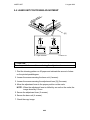
PREVENTION OF PHYSICAL INJURY
1. Before disassembling or assembling parts of the copier and peripherals,
make sure that the copier power cord is unplugged.
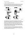
2. The wall outlet should be near the copier and easily accessible.
3. Note that some components of the copier and the paper tray unit are
supplied with electrical voltage even if the main switch is turned off.
4. If any adjustment or operation check has to be made with exterior
covers off or open while the main switch is turned on, keep hands away
from electrified or mechanically driven components.
5. If the Start key is pressed before the copier completes the warm-up
period (the Start key starts blinking red and green alternatively), keep
hands away from the mechanical and the electrical components as the
copier starts making copies as soon as the warm-up period is
completed.
6. The inside and the metal parts of the fusing unit become extremely hot
while the copier is operating. Be careful to avoid touching those
components with your bare hands.
HEALTH SAFETY CONDITIONS
1. Never operate the copier without the ozone filters installed.
2. Always replace the ozone filters with the specified ones at the specified
intervals.
3. Toner and developer are non-toxic, but if you get either of them in your
eyes by accident, it may cause temporary eye discomfort. Try to remove
with eye drops or flush with water as first aid. If unsuccessful, get
medical attention.
OBSERVANCE OF ELECTRICAL SAFETY STANDARDS
1. The copier and its peripherals must be installed and maintained by a
customer service representative who has completed the training course
on those models.
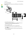
2. The RAM board on the system control board has a lithium battery which
can explode if replaced incorrectly. Replace the battery only with an
identical one. The manufacturer recommends replacing the entire RAM
board. Do not recharge or burn this battery. Used batteries must be
handled in accordance with local regulations.
SAFETY AND ECOLOGICAL NOTES FOR DISPOSAL
1. Do not incinerate toner bottles or used toner. Toner dust may ignite
suddenly when exposed to an open flame.
2. Dispose of used toner, developer, and organic photoconductors in
accordance with local regulations. (These are non-toxic supplies.)
3. Dispose of replaced parts in accordance with local regulations.
4. When keeping used lithium batteries in order to dispose of them later,
do not put more than 100 batteries per sealed box. Storing larger
numbers or not sealing them apart may lead to chemical reactions and
heat build-up.
LASER SAFETY
The Center for Devices and Radiological Health (CDRH) prohibits the repair
of laser-based optical units in the field. The optical housing unit can only be
repaired in a factory or at a location with the requisite equipment. The laser
subsystem is replaceable in the field by a qualified Customer Engineer. The
laser chassis is not repairable in the field. Customer engineers are therefore
directed to return all chassis and laser subsystems to the factory or service
depot when replacement of the optical subsystem is required.
WARNING
Use of controls, or adjustment, or performance of procedures other than
those specified in this manual may result in hazardous radiation exposure.
WARNING FOR LASER UNIT
WARNING: Turn off the main switch before attempting any of the
procedures in the Laser Unit section. Laser beams can
seriously damage your eyes.
CAUTION MARKING:
!
DANGER
INVISIBLE LASER RADIATION
WHEN OPEN.
AVOID DIRECT EXPOSURE TO
BEAM.
>PS<
>P S<
!
DANGER
INVISIBLE LASER RADIATION
WHEN DISCONNECT OPTICAL
FIBER CABLE.
AVOID DIRECT EXPOSURE TO
BEAM.
>PS<
SECTION 1
OVERALL MACHINE
INFORMATION
1 August 1996
SPECIFICATIONS
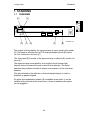
1. SPECIFICATIONS
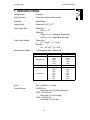
Configuration:
Desktop
Copy Process:
Dry electrostatic transfer system
Originals:
Sheet/Book
Original Size:
Maximum A3/11" x 17"
Copy Paper Size:
Maximum
A3/11" x 17"
Minimum
A5/81/2" x 51/2" sideways (Paper tray)
A6/51/2" x 81/2" lengthwise (By-pass)
Copy Paper Weight:
Paper tray:
60 ~ 90 g/m2, 16 ~ 24 lb
By-pass:
60 ~ 157 g/m2, 16 ~ 42 lb
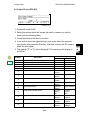
Reproduction Ratios:
5 Enlargement and 7 Reduction
Enlargement
Full size
Reduction
A4/A3 Version
400%
200%
141%
122%
115%
100%
93%
87%
82%
71%
65%
50%
25%
LT/DLT Version
400%
200%
155%
129%
121%
100%
93%
85%
77%
74%
65%
50%
25%
Zoom:
25% to 400% in 1% steps
Power Source:
120V/60 Hz:
More than 12 A (for North America)
220V ~ 240V/50 Hz:
More than 7 A (for Europe)
220V ~ 240V/60 Hz:
More than 7 A (for Asia)
1-1
SPECIFICATIONS
1 August 1996
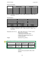
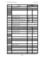
Power Consumption:
Maximum
Copying
Warm-up
Stand-by
Auto Shut Off
Mainframe Only
120V
220V ~ 240V
Less than 1.1 kW Less than 850 W
Approx. 470 W
Approx. 500 W
Approx. 1.0 kW
Approx. 750 W
Approx. 130 W
Approx. 130 W
Approx. 2.0 W
Approx. 2.2 W
Full System
120V
220V ~ 240V
Less than 1.2 kW Less than 1 kW
Approx. 500 W
Approx. 530 W
Approx. 1.0 kW
Approx. 750 W
Approx. 140 W
Approx. 140 W
Approx. 2.2 W
Approx. 2.4 W
NOTE: Full System: Mainframe + ADF + Paper Tray Unit + Duplex Tray +
1-bin Sorter
Noise Emission:
Mainframe Only
1. Sound Power Level
Copying
61.5 dB(A)
Stand-by
30.0 dB(A)
2. Sound Pressure Level at the Operator Position
Copying
47.5 dB(A)
Stand-by
17.5 dB(A)
Full System
64.5 dB(A)
30.0 dB(A)
52.0 dB(A)
17.5 dB(A)
NOTE: The above measurements were made in accordance with ISO 7779.
Full System: Mainframe + ADF + Paper Tray Unit + Duplex Tray +
1-bin Sorter
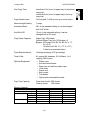
Dimensions (W x D x H):
550 x 580 x 652 mm (21.7" x 22.9" x 25.7")
Measurement Conditions
1) With by-pass feed table closed
2) Without the optional paper tray unit
3) Without the ADF
Weight:
Less than 57 kg (126 lb)
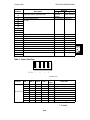
Copying Speed in Multicopy mode (copies/minute):
No optional memory
With 4MB or 8MB
optional memory
Warm-up Time
A4 sideways/
11" x 81/2"
15
A3/11" x 17"
B4/81/2" x 14"
9
10
11
12
20
Less than 30 seconds (20°C, 68°F): 115V
machine
Less then 35 seconds (20°C, 68°F): 230V
machine
1-2
1 August 1996
SPECIFICATIONS
First Copy Time:
Less than 9.8 s (from 1st paper tray to face down
copy tray)
Less than 8.8 s (from 1st paper tray to face up
copy tray)
Copy Number Input:
Ten-key pad, 1 to 99 (count up or count down)
Manual Image Density:
7 steps
Automatic Reset:
60 s is the standard setting; it can be changed
with a UP mode.
Auto Shut Off
15 min. is the standard setting; it can be
changed with a UP mode.
Copy Paper Capacity:
Paper Tray: 250 sheets
Optional Paper Tray Unit: 500 sheets x 2
Bypass: 100 sheets (A4, B5, A5, B6, 8.5 x 11",
5.5 x 8.5")
10 sheets (A3, B4, 11 x 17", 8 x 13")
1 sheet (non-standard sizes)
Toner Replenishment:
Cartridge exchange (216 g/cartridge)
Toner Yield:
8 k copies (A4 sideways, 6% full black, 1 to 1
copying, ADS mode)
Optional Equipment:
Copy Tray Capacity
•
•
•
•
•
•
•
•
Platen cover
Auto document feeder
Paper tray unit with two paper trays
1-bin sorter
Duplex unit
Key counter
Tray heater
Optical anti-condensation heater
Face down mode: 500 sheets
Face up mode:
100 sheets
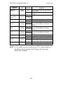
Memory Capacity:
Multi duplex copy
Sort, Rotate Sort
Number of pages
A4, LT
B4, LG
A3, DLT
A4 6%
ITU-T#4
Standard (4 MB)
X
O
X
X
35
15
Optional 4 MB
O
O
O
O
99
45
Optional 8 MB
O
O
O
O
99
75
X: Not AvailableO: Available
1-3
MACHINE CONFIGURATION
1 August 1996
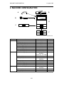
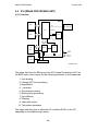
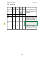
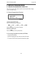
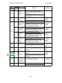
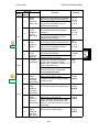
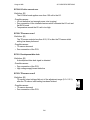
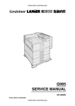
2. MACHINE CONFIGURATION
D
A
B
E
C
F
A193V501.wmf
Version
Copier
Fax
Item
Copier
ADF (Option)
Paper Tray Unit (Option)
Duplex Unit (Option)
1-bin Sorter (Option)
Platen Cover (Option)
Memory 4MB (Option)
Memory 8MB (Option)
Fax Controller (Option)
Machine Code
A193
A628
G697
G694
A629
A645
A642-01
A642-02
A639-01 (115V),
-02(230V),
-03(France), -04 (TWN)
H160
A644-01(115V),
-02(230V)
A641
H130-54
H130-52
A640
A643-00 (115V),
-01(230V)
A643-02
A643-03
Telephone (Option)
ISDN (Option)
Printer
HDD (Option)
Memory Card (Option)
Function Card (Option)
Page Memory (Option)
Printer Controller (Option)
PS Option (Option)
HDD (Option)
1-4
No.
E
D
F
C
B
A
1 August 1996
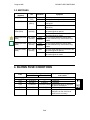
PAPER PATH
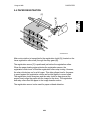
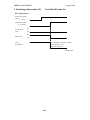
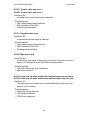
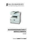
3. PAPER PATH
Optional
1-bin
Sorter
Face
Down Tray
Face Up
Tray
Optional
Duplex
Tray
Paper
Tray
Optional
Paper
Tray Unit
A193V005.wmf
1-5
MECHANICAL COMPONENT LAYOUT
1 August 1996
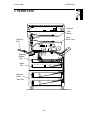
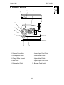
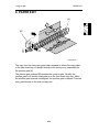
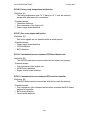
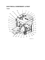
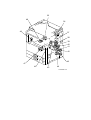
4. MECHANICAL COMPONENT LAYOUT
2
35
3
4
5 6
7
8
9
10
11
1
12
13
34
33
14
32
15
31
30
16
17
29
18
19
28
20
27
A193V502.wmf
26
25
24
1-6
23
22
21
1 August 1996
MECHANICAL COMPONENT LAYOUT
1. 2nd Mirror
22. Transfer Roller
2. 1st Mirror
23. Separation Brush
3. DF Exposure Glass
24. Transport Vacuum Fan
4. Xenon Lamp
25. Pressure Roller
5. Exposure Glass
26. Hot Roller
6. Original Width Sensors
27. Fusing Exit Roller
7. 1st Mirror
28. Left Vertical Door/Face Up
Tray
8. Barrel Toroidal Lens (BTL)
9. Original Length Sensors
10. Lens
11. SBU Board
12. Scanner Motor
13. F-theta Mirror
14. 2nd Mirror (Laser Unit)
15. PCU
29. Junction Gate
30. Hot Roller Strippers
31. Left Vertical Roller
32. Lower Exit Sensor
33. Polygonal Mirror Motor
34. 3rd Mirror
35. Face Down Tray
16. Toner Bottle
17. By-pass Feed Roller
18. By-pass Table
19. Relay Rollers
20. Paper Feed Rollers
21. Bottom Plate
1-7
ELECTRICAL COMPONENT DESCRIPTIONS
1 August 1996
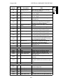
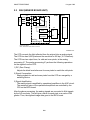
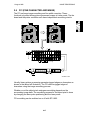
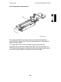
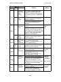
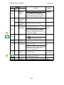
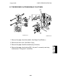
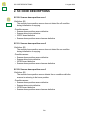
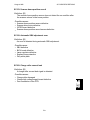
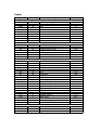
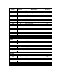
5. ELECTRICAL COMPONENT DESCRIPTIONS
Refer to the electrical component layout and the point-to-point diagram on the
waterproof paper in the pocket for the locations of these components.
Index
Description
No.
Printed Circuit Boards
High Voltage Supply
PCB1
54 Board
Symbol
PCB2
50
PCB3
58
PCB4
61
PCB5
62
PCB6
51
PCB7
55
PCB8
52
PCB9
53
Lamp Stabilizer
PSU
LD Unit
Operation Panel
SBU
IOCSS
BICU
MSU
Motors
M1
45
M2
36
M3
47
M4
49
M5
37
M6
35
Exhaust Fan
Sensors
S1
S2
S3
33
31
28
S4
27
Upper Exit
Lower Exit
Left Vertical Door
Left Door
Main
Scanner Drive
Transport Vacuum
Fan
Polygonal Mirror
Toner Supply
Relay
S5
17
S6
S7
10
29
PCU
Fusing Exit
Note
Supplies high voltage to the drum charge
roller, development roller, transfer roller, and
discharge brush.
Provides dc power for the exposure lamp.
Provides dc power to the system and ac
power to the fusing lamp.
Controls the laser diode.
Controls the touch panel display and LED
matrix, and monitors the key matrix.
Contains the CCD, and outputs a video
signal to the BICU board.
Controls the mechanical parts of the printer.
Controls all copier functions both directly or
through other control boards.
Compressed the image data, stores the
data, and applies the image editing.
Drives the main body components.
Drives the 1st and 2nd scanners (dc stepper
motor).
Aids paper transportation from the transfer
roller to the fusing unit.
Turns the polygonal mirror.
Rotates the toner bottle to supply toner to
the toner supply unit.
Removes heat from around the fusing unit.
Detects misfeeds.
Detects misfeeds.
Cuts the +5 and +24 Vdc power lines.
Detects whether the left door is open or
closed.
Detects the leading edge of paper from the
paper tray and duplex unit to determine the
stop timing of the paper feed clutch and
duplex feed motor. Also detects misfeeds.
Detects when a new PCU is installed.
Detects misfeeds.
1-8
1 August 1996
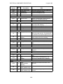
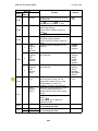
ELECTRICAL COMPONENT DESCRIPTIONS
Symbol
Index
No.
S8
9
S9
14
S10
15
S11
16
S12
12
S13
11
S14
59
S15
4
S16
5
S17
6
S18
3
S19
1
S20
23
Switches
SW1
SW2
SW3
21
32
13
SW4
20
SW5
19
SW6
26
Description
Charge Roller H.P
Upper Tray Paper
End
Lower Tray Paper
End
By-pass Feed Paper
End
Registration
By-pass Feed Paper
Width
Humidity
Original Width
Original Length-1
Original Length-2
Platen Cover
Scanner H.P.
Toner Density (TD)
AC
Main
Right Vertical Guide
Upper Paper Size
Lower Paper Size
Front Door Safety
Note
Informs the CPU when the drum charge
roller is at home position.
Informs the CPU when the upper paper tray
runs out of paper.
Informs the CPU when the lower paper tray
runs out of paper.
Informs the CPU when there is no paper in
the by-pass tray.
Detects the leading edge of the copy paper
to determine the stop timing of the paper
feed clutch, and detects misfeeds.
Detects the width of the paper in the by-pass
feed table.
Monitors the humidity around the PCU.
Detects the width of the original. This is one
of the APS (Auto Paper Select) sensors.
Detects the length of the original. This is one
of the APS (Auto Paper Select) sensors.
Detects the length of the original. This is one
of the APS (Auto Paper Select) sensors.
Informs the CPU whether the platen cover is
up or down (related to APS/ARE functions).
ARE: Auto Reduce and Enlarge
Informs the CPU when the 1st and 2nd
scanners are at the home position.
Detects the amount of toner inside the
development unit.
Supplies power to the copier.
Supplies power to operate the machine.
Cuts the +5 and +24 Vdc power lines.
Determines what size of paper is in the
upper paper tray.
Determines what size of paper is in the lower
paper tray.
Cuts the +5VLD and +24V dc power lines
and detects whether the front cover is open
or not.
Magnetic Clutches
MC1
46
MC2
MC3
42
43
MC4
40
MC5
41
Charge Roller Contact Controls the touch and release movement of
the drum charge roller.
Upper Relay
Drives the upper relay rollers.
Lower Relay
Drives the lower relay rollers.
By-pass Feed
Starts paper feed from the by-pass feed
table.
Upper Paper Feed
Starts paper feed from the upper paper tray.
1-9
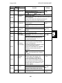
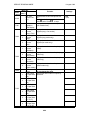
ELECTRICAL COMPONENT DESCRIPTIONS
Symbol
MC6
MC7
MC8
Index
Description
No.
44 Lower Paper Feed
39 Registration
Development
38
1 August 1996
Note
Starts paper feed from the lower paper tray.
Drives the registration rollers.
Drives the development roller.
Solenoids
SOL1
48
Junction Gate
Moves the junction gate to direct copies to
the face up or face down copy tray.
Quenching
Neutralizes any charge remaining on the
drum surface after cleaning.
Applies light to the original for exposure.
Provides heat to the hot roller.
Lamps
L1
60
L2
L3
2
8
Scanner
Fusing
Heaters
Tray (option)
H1
18
H2
34
Turns on when the main switch is off to keep
paper in the paper tray dry. Tray heaters are
also available for the optional paper feed unit.
Turns on when the main switch is off to
prevent moisture from accumulating.
Anti-condensation
(option)
Thermistors
TH1
24
TH2
22
Charge Roller
Monitors the temperature of the drum charge
roller.
Monitors the temperature of the hot roller.
Fusing
Thermofuses
TF1
7
Fusing
Provides back-up overheat protection in the
fusing unit.
Total
Keeps track of the total number of copies
made.
Used for control of authorized use. The
copier will not operate until it is installed.
Counters
CO1
25
CO2
---
Key
(option)
Others
LSD1
30
NF
56
CB
57
Laser
Synchronization
Detector
Noise Filter
(230V machine only)
Circuit Breaker
(230V machine only)
Detects the laser beam at the start of the
main scan.
Removes electrical noise from the AC input
line.
Guards against voltage surges in the AC
input line.
1-10
1 August 1996
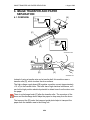
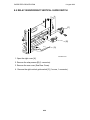
DRIVE LAYOUT
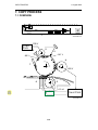
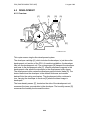
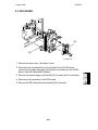
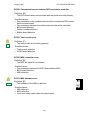
6. DRIVE LAYOUT
2
1
3
10
9
8
7
4
A193V503.wmf
6
5
1. Scanner Drive Motor
6. Lower Paper Feed Clutch
2. Development Clutch
7. Lower Relay Clutch
3. Charge Roller Contact
8. Upper Relay Clutch
4. Main Motor
9. Upper Paper Feed Clutch
5. Registration Clutch
10. By-pass Feed Clutch
1-11
COPY PROCESS
1 August 1996
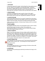
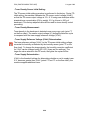
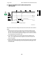
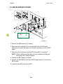
7. COPY PROCESS
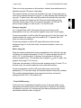
7.1 OVERVIEW
1
A193V505.wmf
-1750 V
Pow er
Pack
2
8
3
-140 V
-90 V
-900 V
4
7
-600 V
6
5
+15 µA
+2 kV
Pow er Pack
A193V506.wmf
1-12
1 August 1996
COPY PROCESS
1. EXPOSURE
A xenon lamp exposes the original. Light reflected from the original passes to
the CCD, where it is converted into an analog data signal. This data is
converted to a digital signal, processed, and stored in the memory. At the
time of printing, the data is retrieved and sent to the laser diode. For
multi-copy runs, the original is scanned once only and stored to the memory.
2. DRUM CHARGE
In the dark, the charge roller gives a negative charge to the organic
photo-conductive (OPC) drum. The charge remains on the surface of the
drum because the OPC layer has a high electrical resistance in the dark.
3. LASER EXPOSURE
The processed data scanned from the original is retrieved from the memory
and transferred to the drum by a laser beam, which forms an electrical latent
image on the drum surface. The amount of charge remaining as a latent
image on the drum depends on the laser beam intensity, which is controlled
by the BICU board.
4. DEVELOPMENT
The magnetic developer brush on the development rollers comes in contact
with the latent image on the drum surface. Toner particles are
electrostatically attracted to the areas of the drum surface where the laser
reduced the negative charge on the drum.
5. IMAGE TRANSFER
Paper is fed to the area between the drum surface and the transfer roller at
the proper time for aligning the copy paper and the developed image on the
drum surface. Then, the transfer roller applies a high positive charge to the
reverse side of paper. This positive charge produces an electrical force which
pulls the toner particles from the drum surface on to the paper. At the same
time, the paper is electrically attracted to the transfer roller.
6. PAPER SEPARATION
Paper separates from the drum as a result of the electrical attraction between
the paper and the transfer roller. The discharge brush helps separate the
paper from the drum.
7. CLEANING
The cleaning blade removes any toner remaining on the drum surface after
the image is transferred to the paper.
8. QUENCHING
The light from the quenching lamp electrically neutralizes the charge on the
drum surface.
1-13
BOARD STRUCTURE
1 August 1996
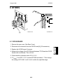
8. BOARD STRUCTURE
8.1 OVERVIEW
Scanner
Motor
Flat Cable
SBU
Harness
LD Unit
Harness
Polygon
Mirror
Motor
Scanner Sensors
DF Motor
IOCSS
BICU
DF Sensors,
Solenoids
Laser Synchronization
Signal = Optical Cable
Laser Printer
Sensors, Solenoids,
Motors, Clutches
High Voltage Supply
MSU
Additional
Memory
Peripheral Sensors,
Motors, Solenoids,
Clutches
Operation
Panel
Harness
Flat Cable
Fax Controller
Mother Board
Printer
Controller
Standard
Option
A193V504.wmf
1-14
1 August 1996
BOARD STRUCTURE
8.2 DESCRIPTION
1. BICU (Base Engine and Image Control Unit)
This is the main board. It controls the following functions:
• Engine sequence
• Scanner, laser printer engine
• Timing control for peripherals
• Image processing, video control
• Operation control
• Corresponding application boards
• Machine control, system control
2. IOCSS (I/O and Customer Support System Unit)
The IOCSS board handles the following functions:
• Drive control for the sensors, motors, solenoids of the printer and scanner
• PWM control for the high voltage control board
• Serial interfaces with peripherals
• Circuit for fusing control
3. SBU (Sensor Board Unit)
The SBU deals with the analog signals from the CCD and converts them into
digital signals.
4. MSU (Memory Super-charger Unit)
The MSU stores and compresses the image data. It also does image editing
on the data if requested by the user. An extra 4 MB or 8 MB of memory can
be added (see below).
5. Additional Memory (Option)
This is an additional image memory board for the MSU.
6. LD Unit
This is the laser diode drive circuit board.
7. Mother Board
This is the printer control board as well as the BICU interface board. It
receives the signals from the printer control board and sends signals to the
printer control board.
1-15
SECTION 2
DETAILED SECTION
DESCRIPTIONS
1 August 1996
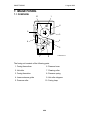
SCANNING
1. SCANNING
1.1
OVERVIEW
[A]
[E]
A193D001.wmf
[G]
[F]
[D]
[C]
[B]
The original is illuminated by the exposure lamp (a xenon lamp in this model)
[A]. The image is reflected onto a CCD (charge coupled device) [B] via the
1st, 2nd, 3rd mirrors, and lens [C].
The 1st scanner [D] consists of the exposure lamp, a reflector [E], and the 1st
mirror [F].
The exposure lamp is energized by a dc supply to avoid uneven light
intensity as the 1st scanner moves in the sub scan direction. The entire
exposure lamp surface is frosted to ensure even exposure in the main scan
direction.
The light reflected by the reflector is of almost equal intensity, to reduce
shadows on pasted originals.
An optics anti-condensation heater [G] is available as an option. It can be
installed on the left side of the inner cover. It turns on whenever the power
cord is plugged in.
2-1
SCANNING
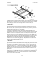
1.2
1 August 1996
SCANNER DRIVE
[H]
[G]
[B]
[A]
[E]
[D]
[G]
[F]
[C]
[E]
A193D546.wmf
A stepper motor is used to drive the scanner. The 1st and 2nd scanners [A,B]
are driven by this scanner drive motor [C] through the timing belt [D], scanner
drive pulley [E], scanner drive shaft [F], and two scanner wires [G].
– Book mode –
The scanner drive board controls and operates the scanner drive motor. In
full size mode, the 1st scanner speed is 90 mm/s during scanning. The 2nd
scanner speed is half that of the 1st scanner.
In reduction or enlargement mode, the scanning speed depends on the
magnification ratio (M: 0.25 to 4.00). The returning speed is always the same,
whether in full size or magnification mode. The image length change in the
sub scan direction is done by changing the scanner drive motor speed, and
in the main scan direction it is done by image processing on the BICU board.
Magnification in the sub-scan direction can be adjusted by changing the
scanner drive motor speed using SP4-101. Magnification in the main scan
direction can be adjusted using SP4-008.
– ADF mode –
The scanners are always kept at their home position (the scanner H.P sensor
[H] detects the 1st scanner) to scan the original. The ADF motor feeds the
original through the ADF. In reduction/enlargement mode, the image length
change in the sub-scan direction is done by changing the ADF motor speed.
Magnification in the main scan direction is done in the BICU board, like for
book mode.
Magnification in the sub-scan direction can be adjusted by changing the ADF
motor speed using SP6-007. In the main scan direction, it can be adjusted
with SP4-008, like for book mode.
2-2
1 August 1996
1.3
SCANNING
ORIGINAL SIZE DETECTION IN PLATEN MODE
[B]
[C]
A193D526.wmf
[A]
A193D003.wmf
In the optics cavity for original size detection, there are four reflective sensors
in the 115V machines, and six reflective sensors in the 230V machines. The
Original Width Sensors [A] detect the original width, and the Original Length
Sensors [B] detect the original length. These are the APS (Auto Paper
Select) sensors. Each APS sensor is a reflective photosensor.
While the main switch is on, these sensors are active and the original size
data is always sent to the CPU. However, the CPU checks the data only
when the platen cover is opened.
The original size data is taken by the main CPU when the platen cover
sensor [C] is activated. This is when the platen is positioned about 15 cm
above the exposure glass. At this time, only the sensor(s) located underneath
the original receive the reflected light and switch on. The other sensor(s) are
off. The main CPU can recognize the original size from the on/off signals
from the APS sensors.
If the copy is made with the platen fully open, the main CPU decides the
original size from the sensor outputs when the Start key is pressed.
2-3
SCANNING
1 August 1996
Original Size
Width
Sensors
Length Sensors
A4/A3 version
LT/DLT version
L1
L2
L3
L4
S1
S2
A3
11" x 17"
O
O
O
O
O
O
B4
10" x 14"
O
O
O
O
O
X
F4
81/2" x 14" (8" x 13")
O
O
O
X
X
X
A4–L
81/2" x 11"
O
O
X
X
X
X
B5–L
—
O
X
X
X
X
X
A4–S
11" x 81/2"
X
X
X
X
O
O
B5–S
—
X
X
X
X
O
X
O: ON X: OFF
NOTE: The length sensors L3 and L4 are used only for 230V machines.
For other combinations, "CANNOT DETECT ORIG. SIZE" will be indicated
on the operation panel display.
The above table shows the outputs of the sensors for each original size. This
original size detection method eliminates the necessity for a pre-scan and
increases the machine’s productivity.
However, if the by-pass feeder is used, note that the machine assumes that
the copy paper is lengthwise. For example, if A4 sideways paper is placed on
the by-pass tray, the machine assumes it is A3 paper and scans the full A3
area, disregarding the original size sensors. This can cause excess toner to
be transferred to the transfer roller, so users should be instructed to always
set the paper lengthwise on the by-pass tray. This problem occurs for the first
page only. The registration sensor detects the length of the first page, and
will assume that the following sheets of copy paper are the same length.
Original size detection using the ADF is described in the manual for the ADF.
2-4
1 August 1996
IMAGE PROCESSING
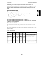
2. IMAGE PROCESSING
OVERVIEW
CCD
2.1
SBU
Fax Controller
Drum
LD Driver
TX
LD
Controller
(GAVD)
IPU
FCI
LDDR
BICU
RX
MSU
Printer
Controller
Fax
Controller
A193D501.wmf
The CCD generates an analog video signal. The SBU (Sensor Board Unit)
converts the analog signal to an 8-bit digital signal, then it sends the digital
signal to the BICU (Base-engine and Image Control Unit) board.
The BICU board can be divided into three image processing blocks; the IPU
(Image Processing Unit), FCI (Fine Character Image), and LD controller
(GAVD)
• IPU: Auto shading, filtering, magnification, γ correction, and gradation
processing
• FCI: Smoothing (binary picture processing mode only)
• LD controller: LD print timing control and laser power PWM control
Finally, the BICU board sends the video data to the LD drive board at the
correct time.
2-5
IMAGE PROCESSING
2.2
1 August 1996
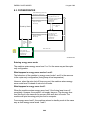
SBU (SENSOR BOARD UNIT)
SBU
Amp.
CCD
ODD
EVEN
BICU
Z/C
Z/C
A/D
AGC
Vin
Reference
Controller
ref
IPU
Analog
Processing IC
Z/C: Zero Clamp
AGC: Automatic Gain Control Circuit
A193D502.wmf
The CCD converts the light reflected from the original into an analog signal.
The CCD line has 5,000 pixels and the resolution is 400 dpi (15.7 lines/mm).
The CCD has two output lines, for odd and even pixels, to the analog
processing IC. The analog processing IC performs the following operations
on the signals from the CCD:
1) Z/C (Zero Clamp):
Adjusts the black level reference for even pixels to match the odd pixels.
2) Signal Composition:
Analog signals for odd and even pixels from the CCD are merged by a
switching device.
3) Signal Amplification
The analog signal is amplified by operational amplifiers in the AGC circuit.
The maximum gains of the operational amplifiers are controlled by the
CPU on the BICU board.
After the above processing, the analog signals are converted to 8-bit signals
by the A/D converter. This will give a value for each pixel on a scale of 256
grades. Then, the digitized image data goes to the BICU board.
2-6
1 August 1996
2.3
IMAGE PROCESSING
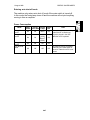
AUTO IMAGE DENSITY (ADS)
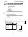
[A]
Sub scan direction
A193D004.wmf
This mode prevents the background of an original from appearing on copies.
The copier scans the auto image density detection area [A] as shown in the
diagram. This corresponds to a few mm at one end of the main scan line. As
the scanner scans down the page, the IPU on the BICU detects the peak
white level for each scan line. The IPU determines the reference value for the
A/D conversion for a particular scan line using the peak white level for that
scan line. Then, the IPU sends the reference value data to the reference
controller on the SBU.
When an original with a gray background is scanned, the density of the gray
area is the peak white level density. Therefore, the original background will
not appear on copies. Because peak level data is taken for each scan line,
ADS corrects for any changes in background density down the page.
As with previous digital copiers, the user can select manual image density
when selecting auto image density mode, and the machine will use both
settings when processing the original.
2-7
IMAGE PROCESSING
2.4
1 August 1996
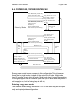
IPU (IMAGE PROCESSING UNIT)
2.4.1 Overview
BICU
SBU
+
Tx
IPU
Fax controller
CPU BUS
MSU
CPU
+
GAVD
FCI
1 bit
Data
+
+
+
LD
Unit
+
Printer
controller
8 bit
Data
Rx
Fax Controller
A193D527.wmf
The image data from the SBU goes to the IPU (Image Processing Unit) IC on
the BICU board, which carries out the following processes on the image data:
1. Auto shading
2. Filtering (MTF and smoothing)
3. Magnification
4. γ correction
5. Grayscale processing
6. Binary picture processing
7. Error diffusion
8. Dithering
9. Video path control
10. Test pattern generation
The image data then goes to either the LD controller (GAVD) or the FCI
depending on the selected copy modes.
2-8
1 August 1996
IMAGE PROCESSING
2.4.2 Image Processing Path
SBU
Text mode
Text/Photo
mode
IPU
ADS and Auto
Shading
Photo mode
MTF
Correction
Smoothing
Main Scan
Magnification/
Reduction
γ Correction
(Scanner)
Grayscale
Processing
Dithering
Error Diffusion
Binary Picture
Processing
Line Width
Correction
Image Compression/
Decompression, Image
Rotation/Adjust Image
Fax Controller
Printer
Controller
Video Path Controller
Edge Smoothing
Line Width Correction
BICU
MSU
FCI
Laser Diode Power
Modulation
γ Correction (Printer)
LDDR
A193D506.wmf
2-9
IMAGE PROCESSING
1 August 1996
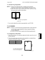
2.4.3 Auto Shading
A193D517.wmf
As with the previous digital copiers, there are two auto shading methods. One
is black level correction and the other is white level correction. Auto shading
corrects errors in the signal level for each pixel.
1) Black Level Correction
The CPU reads the black dummy data from one end of the CCD signal (64
pixels at the end are blacked off) and takes the average of the black dummy
data. Then, the CPU deletes the black level value from each image pixel.
2) White Level Correction
Before scanning the original, the machine reads a reference waveform from
the white plate. The average of the white video level for each pixel is stored
as the white shading data in the FIFO memory in the IPU chip.
The video signal information for each pixel obtained during image scanning is
corrected by the IPU chip.
In book mode, auto shading is done at the beginning of each scan.
In ADF mode, auto shading is done at a specific time interval. This interval
can be set with SP4-913 (the default setting is 30 seconds). The machine
waits until the end of the page before doing the auto shading.
2-10
1 August 1996
IMAGE PROCESSING
2.4.4 Filtering and Main Scan Magnification/Reduction
1. Overview
After auto shading, the image data is processed by both filtering and main
scan magnification. However, to reduce the occurrence of moire in the image,
the processing order is different depending on the reproduction ratio, as
follows.
1) Reduction and Full size
Main Scan Reduction → Filtering
2) Enlargement
Filtering → Main Scan Magnification
2. Filtering
There are two software filters for enhancing the desired image qualities of the
selected original mode: the MTF filter and the smoothing filter.
The MTF filter emphasizes sharpness and is used in Text and Text/Photo
modes. The smoothing filter is used in Photo mode.
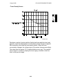
The relationships between the coefficient of the filter and the filter strengths
are as follows. Note that these relationships are for copier mode only. Fax
mode has its own unique table. (Refer to the fax section.)
The filter strengths for each mode can be adjusted with SP4-407.
NOTE: Never select "1." Abnormal images may result.
A193D503.wmf
2-11
IMAGE PROCESSING
1 August 1996
3. Main Scan Magnification/Reduction
Reduction and enlargement in the sub scan direction are done by changing
the scanner speed. However, reduction and enlargement in the main scan
direction are handled by the IPU chip. The processing for main scan
magnification/reduction is the same as in the previous digital machines.
[A]
A193D504.wmf
When making a copy using the ADF, the magnification circuit creates a
mirror image. This is because the scanning starting position in the main scan
direction is at the other end of the scan line in ADF mode (as compared with
platen mode). In platen mode, the original is placed face down on the
exposure glass, and the corner at [A] is at the start of the main scan. The
scanner moves down the page. In ADF mode, the ADF feeds the leading
edge of the original to the DF exposure glass, and the opposite top corner of
the original is at the main scan start position.
To create the mirror image, the CPU stores the main scan line data in the
LIFO (Last In First Out) memory of the magnification block, from the last
pixel. When loading the main scan line data from the LIFO memory, the CPU
loads the first pixel of the main scan line.
2-12
1 August 1996
IMAGE PROCESSING
2.4.5 Gamma (γ) Correction
Gamma correction ensures accurate generation of the various shades in the
gray scale from black to white, accounting for the characteristics of the
scanner and printer.
Scanner gamma correction corrects the data output to the IPU to account for
the characteristics of the scanner (e.g., CCD response, scanner optics).
Printer gamma correction corrects the data output from the IPU to the laser
diode to account for the characteristics of the printer (e.g., the characteristics
of the drum, laser diode, and lenses).
The data for the scanner gamma correction is fixed and stored in the
memory. The printer gamma correction can be adjusted with SP 2-916.
2.4.6 Gradation Processing
These are four types of gradation processing:
• Grayscale processing: This has 64 output levels for each pixel, and is
used only in one-to-one copy mode.
• Binary picture processing: This has only two output levels (black and
white), and is used in memory copying (e.g., multiple copy, rotate sort,
and editing image) and facsimile transmission.
• Error diffusion: In Text/Photo mode, this is used with either grayscale
processing or binary processing.
• Dithering: In Photo mode, this is used with either grayscale processing or
binary processing.
These four processes are used as follows.
1) Grayscale processing mode
Text mode:
Grayscale processing
Text/Photo mode:
Grayscale processing + error diffusion
Photo mode:
Grayscale processing + dithering
2) Binary picture processing mode
Text mode:
Binary picture processing
Text/Photo mode:
Binary picture processing + error diffusion
Photo mode:
Binary picture processing + dithering
Copying using the memory (e.g., multiple copying) and fax mode always use
binary picture processing. (Users requiring grayscale mode output for
multiple copies will have to take a succession of one-to-one copies.)
For one-to-one copying, the processing mode used depends on the setting of
SP 4-403. The factory setting is for grayscale processing.
2-13
IMAGE PROCESSING
1 August 1996
1. Grayscale Processing
As stated on the previous page, this process generates up to 64 image
density levels for each pixel. To realize this, this machine uses a form of
pulse width modulation. In this machine, pulse width modulation consists of
the following processes:
• Laser diode pulse positioning
• Laser diode power/pulse width modulation
Laser diode power and pulse width modulation is done by the laser diode
drive board (LDDR), and will be explained in the Laser Exposure section.
Briefly, the width of the laser pulse for a pixel depends on the output level
(from 0 to 63) required for the pixel.
For each pixel, the location of the active (laser on) part of the pixel can be either
at the left side of the pixel, at the center, or at the right side (see fig 2). The
machine determines which method to use depending on the settings of SP
2-903. There are different settings for pixels at the left edge, at the right edge,
and in the middle of a series of black/grey pixels across the main scan, and for
single black pixels with white pixels at the left and right. The edges of characters
and lines become clearer with this processing.
Fig. 1
A193D518.wmf
Fig. 2
A193D507.wmf
2. Binary Picture Processing
Each video signal level is converted from 8-bit to 1-bit (black and white image
data) in accordance with a threshold value.
The threshold value can be adjusted with SP 4-418.
The printout density of the black pixel depends on the pixel type (left, center,
or right of a series, or isolated, in the same way as for grayscale processing).
These values can be adjusted with SP2-904.
2-14
1 August 1996
IMAGE PROCESSING
3. Error Diffusion
This is used only in Text/Photo mode.
The error diffusion process reduces the difference in contrast between light
and dark areas of a halftone image. Each pixel is corrected using the
difference between it and the surrounding pixels. The corrected pixels are
then compared with a error diffusion matrix. Separate error diffusion matrixes
are used for copy mode and fax mode.
1) Grayscale processing mode
The output image signal level has 9 levels (from white to black).
There is only one matrix available.
2) Binary picture processing mode
The output image signal level has just 2 levels (white and black).
The threshold level can be changed with SP4-418-2.
4. Dithering
This is only used in Photo mode.
Each pixel is compared with a pixel in a dither matrix. Several matrixes are
available, to increase or decrease the detail on the copy.
1) Grayscale processing mode
The matrix type can be selected with SP4-421-1 and with UP mode.
2) Binary picture processing
The matrix type can be selected with SP4-421-2 and with UP mode.
2.4.7 Line Width Correction
This function is effective only in Letter mode.
Usually, lines will bulge in the main scan direction as a result of the
negative/positive development system that is used in this model. So, pixels
on edges between black and white areas are compared with adjacent pixels,
and if the pixel is on a line, the line thickness will be reduced.
The line width correction in grayscale processing mode is done in the IPU,
and in binary processing mode, it is done in the FCI chip.
2-15
IMAGE PROCESSING
2.5
1 August 1996
MSU (MEMORY SUPER-CHARGER UNIT)
IPU
DRAM
Memory
Controller
CPU
BUS
MSU
BICU
A193D528.wmf
The MSU consists of the memory controller and the DRAM. The functions of
each device are as follows.
Memory Controller:
Compressing the 1-bit image data
Image rotation
Image data transfer to the DRAM
DRAM (standard 4MB):
Stores the compressed data (2 MB)
Working area (2 MB)
The data which was treated with binary picture processing goes to the MSU.
The data is first compressed using the MMR process and the compressed
data is stored in the DRAM. When printing, the data from the DRAM goes
back to the memory controller, where the data is decompressed and image
editing is done (e.g., image rotation, repeat image, combine image).
The memory capacity changes when optional memory is installed on the
MSU board. The copier functions for each memory combination are as
follows.
Multi duplex copy
Sort, Rotate Sort
Number of pages
A4, LT
B4, LG
A3, DLT
A4 6%
ITU-T#4
(12% black)
Standard (4 MB)
X
O
X
X
35
15
Optional 4 MB
O
O
O
O
99
45
X: Not Available
2-16
Optional 8 MB
O
O
O
O
99
75
O: Available
1 August 1996
2.6
IMAGE PROCESSING
FCI (FINE CHARACTER AND IMAGE)
The FCI performs image smoothing and line width correction. These
functions only affect binary picture processed images in Letter mode. The fax
board and the printer controller each have independent smoothing circuits.
A193D511.wmf
Usually, binary picture processing generates jagged edges on characters as
shown in the above left illustration. The FCI reduces jagged edges of
characters using the image smoothing process.
Whether or not the object pixel undergoes smoothing depends on the
surrounding image data. The smoothing process for the object pixel is done
by changing the laser pulse positioning and the laser power.
FCI smoothing can be switched on or off with SP 2-902.
2-17
LASER EXPOSURE
1 August 1996
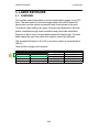
3. LASER EXPOSURE
3.1
OVERVIEW
This machine uses a laser diode to produce electrostatic images on an OPC
drum. The laser diode unit converts image data from the BICU board into
laser pulses, and the optical components direct these pulses to the drum.
To produce a high quality copy image, these are 64 gradations for the laser
pulses, controlled through power modulation and pulse width modulation.
Exposure of the drum by the laser beam creates the latent image. The laser
beam makes the main scan while drum rotation controls the sub scan.
The strength of the beam is 0.6 mW on the drum surface at a wavelength of
780 nm.
There are four polygon motor speeds:
Resolution (dpi)
400 dpi
600 dpi
391.16 dpi
406.4 dpi
Modes
Copy, Fax, and Printer
Printer
Fax (Image rotation)
Fax (mm printing)
Motor Speed (rpm) Data Frequency (MHz)
14173.23
9.276
21259.84
20.872
13860.00
9.216
14400.00
9.216
2-18
1 August 1996
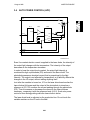
3.2
LASER EXPOSURE
OPTICAL PATH
[B]
[E]
[F]
[D]
[G]
[H]
[A]
[C]
[E]
[D]
[B]
[G]
[H]
[F]
A193D523.wmf
The output path from the laser diode to the drum is shown above.
The LD unit [A] outputs the laser beam to the polygon mirror [B] through the
cylindrical lens [C].
Each surface of the polygon mirror reflects a full main scan line. The laser
beam goes to the F-theta mirror [D], 1st mirror [E], and BTL [F]. The 2nd
mirror [G] reflects the laser beam to the drum through the toner shield glass.
The laser synchronizing detector [H] determines the main scan starting
position.
2-19
LASER EXPOSURE
3.3
1 August 1996
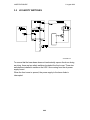
GRADATION CONTROL (LASER POWER MODULATION)
PM
(8 levels)
Data: 0
Data: 3
Data: 7
1
1
Data: 11
Data: 15
Data: 34
Data: 63
7
5
3
1
0
PWM 0
(8 levels) 1 dot
7
2
2
5
7
A193D519.wmf
Black
White
63
A193d520.wmf
To make the latent image, the laser beam illuminates the image area of the
drum surface. The longer the laser is on and the stronger its intensity is, the
darker the developed pixel becomes. Modulating (changing) the width of the
pulse makes the on time of the laser longer or shorter (PWM). There are
eight pulse width levels in this model.
While the laser is on to make one dot, the intensity of the laser is controlled
by power modulation (PM). The laser’s intensity is controlled by the amount
of current sent to the laser diode. Modulating the power makes the laser
brighter or dimmer. There 8 power levels, or laser intensity levels. The power
is modulated only on the final part of the laser pulse (example: see data 11 in
the diagram).
The machine uses the 8 pulse width levels and 8 power levels to create the
64 possible grayscale values for each pixel.
2-20
1 August 1996
3.4
LASER EXPOSURE
AUTO POWER CONTROL (APC)
LD Drive Board
LD5V
LD
IC 1
IC 3
IC 2
DATA
LD1
DATA
LVL2
PD
LDOFF
LVL1
ERR
LEVEL
LDERR
LDOFF
A193D521.wmf
Even if a constant electric current is applied to the laser diode, the intensity of
the output light changes with the temperature. The intensity of the output
decreases as the temperature increases.
In order to keep the output level constant, the output light intensity is
monitored through a photodiode (PD) enclosed in the laser diode. The
photodiode passes an electrical current that is proportional to the light
intensity. The output is not affected by temperature, so it faithfully reflects the
changes in the LD output, without adding anything itself.
Just after the machine is turned on, IC2 on the laser drive board excites the
laser diode at full power and the output of the photodiode is stored as a
reference in IC2. IC2 monitors the current passing through the photodiode
(PD). Then it increases or decreases the current to the laser diode as
necessary, comparing it with the reference level (LVL2). Such auto power
control is done during printing while the laser diode is active.
The laser diode level is adjusted on the production line. Do not touch the
variable resistors on the LD unit in the field.
2-21
LASER EXPOSURE
3.5
1 August 1996
LD SAFETY SWITCHES
A193D008.wmf
To ensure that the laser beam does not inadvertently expose the drum during
servicing, there are two safety switches located at the front cover. These two
switches are installed in series on the LD5 V line coming from the dc power
supply board.
When the front cover is opened, the power supply to the laser diode is
interrupted.
2-22
1 August 1996
PCU (PHOTOCONDUCTOR UNIT)
4. PCU (PHOTOCONDUCTOR UNIT)
4.1
OVERVIEW
10
13
11
12
1
2
3
9
4
6
5
8
7
A193D010.wmf
The PCU consists of the components shown in the above illustration. An
organic photoconduntor (OPC) drum (diameter: 30 mm) is used in this
machine.
1. OPC Drum
8. Toner Collection Coil
2. Doctor Blade
9. Cleaning Blade
3. Developer Cartridge
10. Charge Roller Thermistor
4. TD Sensor
11. Charge Roller
5. Mixing Auger 1
12. Charge Roller Cleaning Pad
6. Mixing Auger 2
13. Humidity Sensor
7. Development Roller
The output of the humidity sensor is used for toner density control processing.
2-23
PCU (PHOTOCONDUCTOR UNIT)
4.2
1 August 1996
DRIVE MECHANISM
[B]
[D]
[C]
[A]
A193D542.wmf
The drive from the main motor [A] is transmitted to the drum through a series
of gears, a timing belt [B], and the drum drive shaft [C]. The main motor has a
drive controller, which outputs a motor lock signal when the rotation speed is
out of the specified range.
The fly-wheel [D] on the end of the drum drive shaft stabilizes the rotation
speed (this prevents banding and jitter from appearing on copies).
2-24
1 August 1996
4.3
PCU (PHOTOCONDUCTOR UNIT)
NEW PCU DETECTION MECHANISM
[A]
A193D535.wmf
[B]
[B]
A193D536.mwf
The PCU sensor [A] detects when a new PCU is installed. Each PCU has an
actuator. When a new PCU is installed in the machine, the actuator [B]
pushes the PCU sensor. The actuator is a sector gear, and this gear
engages with the drum gear. When the drum rotates, the actuator is released
from the drum gear. The actuator drops away from the PCU sensor and
remains in this "down" position for the duration of the PCU’s life.
The machine recognizes when a new PCU has been installed in the machine
because the actuator of the new PCU contacts the PCU sensor. After the
front cover is closed, the machine then performs the TD sensor initial setting
procedure automatically (for about two minutes). During this time, the drum
rotates and the actuator drops away from the sensor.
2-25
PCU (PHOTOCONDUCTOR UNIT)
4.4
1 August 1996
DRUM CHARGE
4.4.1 Overview
[C]
[E]
[D]
[A]
[B]
[F]
A193Dd543.wmf
This copier uses a drum charge roller system instead of a corona wire
scorotron system to charge the drum. For the copy image area or during
roller cleaning, the drum charge roller [A] contacts the surface of the drum [B]
to give it a negative charge.
The drum charge roller system has the following advantages over the corona
wire scorotron charge system.
• The amount of ozone generated during drum charging is less than about
1/10 of that for a corona wire scorotron system.
• The applied voltage is 1/2 ~ 1/3 that of a corona wire scorotron system.
• The efficiency of drum charge is high.
Due to these advantages, no ozone filter is required in this copier.
The high voltage supply board [C] gives a negative dc voltage to the drum
charge roller through the charge roller terminal [D], rear pressure spring [E],
and the rear roller bushing [F]. This gives the drum surface a negative charge
of –900 V.
2-26
1 August 1996
PCU (PHOTOCONDUCTOR UNIT)
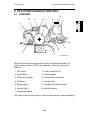
4.4.2 Charge Roller Contact Mechanism
[A]
[B]
[D]
[E]
[C]
[D]
[E]
[C]
A193D543.wmf
A193D014.wmf
To prevent toner from adhering to the drum charge roller and to prevent the
drum charge roller from sticking to the drum, the drum charge roller contacts
the drum only under the following conditions:
• When the image processing area comes under the drum charge roller
• During charge roller cleaning
This function is performed by the charge roller contact clutch [A] (a one-third
turn clutch) charge roller H.P. sensor [B], and cam [C] located at the end of
the clutch shaft. When the clutch is driven one third of a complete rotation,
the pressure lever [D] riding on the cam presses down the drum charge roller
unit [E] to contact the roller with the drum.
When the drum charge roller contacts the drum, the drum charge roller is
turned by the drum.
The following table shows the relationship between the clutch rotation and
each processing mode.
Mode
Copying
Home Position
1/3 turn
Cleaning (see next
page)
1/3 turn
Clutch
OFF
OFF
ON
1/3 turn
Charge Roller
Position
Charge Roller
Contact H.P. Sn
2-27
PCU (PHOTOCONDUCTOR UNIT)
1 August 1996
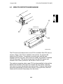
4.4.3 Drum Charge Roller Cleaning
[B]
[A]
[C]
[C]
A193D544.wmf
A193D015.wmf
If the drum charge roller gets dirty, drum charge efficiency decreases. This
affects the copy quality, for example causing vertical black lines.
Drum charge roller cleaning is done for 2 seconds after every copy job.
After the copy job, the charge roller contact clutch is driven another third of a
rotation (see the diagram at the bottom of the previous page). The pressure
lever presses down more, so that the cleaning pad [A] contacts the charge
roller.
After charge roller cleaning, the clutch is driven the final third of the rotation
(until the charge roller H.P sensor [B] is activated) to release the charge roller
from the drum. The pressure lever moves away from the charge roller unit.
Then the charge roller unit is released from the drum by the spring [C].
2-28
1 August 1996
PCU (PHOTOCONDUCTOR UNIT)
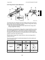
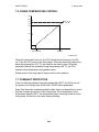
4.4.4 Temperature Compensation
[A]
A193D012-3.wmf
The voltage transferred from roller to drum varies with the temperature
around the drum charge roller. The lower the temperature is, the higher the
applied voltage required.
To compensate for this, the drum charge thermistor [A] detects the
temperature around the drum charge roller. Before the copy job starts, the
CPU monitors the temperature and instructs the high voltage supply board to
correct the charge voltage in accordance with the temperature.
2-29
PCU (PHOTOCONDUCTOR UNIT)
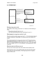
4.5
1 August 1996
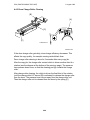
DEVELOPMENT
4.5.1 Overview
[D]
[C]
[G]
[A]
[F]
[B]
[E]
A193D010-3.wmf
This copier uses a single roller development system.
The developer cartridge [A], which includes the developer, is just above the
development unit section of the PCU. At machine installation, the developer
falls into the development unit. The mixing augers [B] transport the developer
and toner to the development roller [C]. Internal permanent magnets in the
development roller attract the developer to the development roller sleeve.
The development roller carries the developer past the doctor blade [D]. The
doctor blade trims the developer to the desired thickness and creates
backspill into the mixing mechanism. The development roller continues to
turn, carrying the developer to the drum [E] where the latent image is
developed.
The toner density sensor [F], located on the side of the development unit,
measures the toner concentration in the developer. The humidity sensor [G]
measures the humidity level around the drum.
2-30
1 August 1996
PCU (PHOTOCONDUCTOR UNIT)
4.5.2 Drive Mechanism
[B]
[A]
[D]
[C]
A193D017.wmf
When the development clutch [D] turns on, main motor drive is transmitted to
the development drive shaft [A] and the development drive gear [B] through a
timing belt [C], and a train of gears.
The development drive gears (except for the gears in the development unit)
are helical gears. These gears are quieter than normal gears. When the PCU
is pushed in, the development drive shaft engages the development roller
gear.
2-31
PCU (PHOTOCONDUCTOR UNIT)
1 August 1996
4.5.3 Mixing
[C]
[A]
[B]
A193D016.wmf
This copier uses 2 mixing augers, [A] and [B], to keep the developer evenly
mixed. Mixing auger 1 [A] transports excess developer, scraped off the
development roller [C] by the doctor blade, towards the front of the machine.
Mixing auger 2 [B] returns the excess developer, along with new toner, to the
rear of the mixing assembly. Here the developer is reapplied to the
development roller.
2-32
1 August 1996
PCU (PHOTOCONDUCTOR UNIT)
4.5.4 Development Bias
[A]
[C]
[B]
A193D534.wmf
This machine uses a negative-positive development system, in which black
areas of the latent image are at a low negative charge (about -140 ± 50 V)
and white areas are at a high negative charge (about -900 V).
To attract negatively charged toner to the black areas of the latent image on
the drum, the high voltage supply board [A] applies a bias of -600 volts to the
development rollers throughout the image development process. The bias is
applied to the development roller shaft [B] through that shaft’s gear [C].
The development bias is kept at 0V until the latent image comes to the
development roller. This is to prevent toner from transferring to the area of
drum near the development roller, which has not yet been charged. The
development bias is then increased to -600 V at the same time as the
development clutch turns on.
The development bias voltage (-600 V) can be adjusted with SP2-201.
2-33
PCU (PHOTOCONDUCTOR UNIT)
1 August 1996
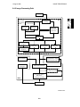
4.5.5 Toner Density Control
- Toner Density Control Flow Chart Copy
1
VT detection
2
VTREF
determination
VTE determination
VT – VTREF = ∆VT
3
Has the
copy job been
finished?
Yes
VT > VTE
No
Yes
No
4
No
∆VT > 0
Yes
Have 30 copies
been made?
Yes
See the Toner End
Detection Flow Chart
No
5
Toner supply motor
on time calculation
A193D545.mwf
Each step is explained in more detail on the following pages.
2-34
1 August 1996
PCU (PHOTOCONDUCTOR UNIT)
- Toner Density Sensor -
A193D522.wmf
Developer consists of carrier particles (ferrite) and toner particles (resin and
pigment). Inside the development unit, developer passes through a magnetic
field created by coils inside the toner density sensor, When the toner
concentration changes, the voltage output of the sensor changes accordingly.
The output from the sensor (VT) is checked before every copy. The machine
tries to keep VT constant by varying the toner supply, as shown in the flow
chart on the previous page.
2-35
PCU (PHOTOCONDUCTOR UNIT)
1 August 1996
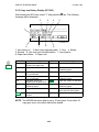
- Toner Density Sensor Initial Setting The TD sensor initial setting procedure is performed in the factory. During TD
initial setting, the machine calibrates the TD sensor control voltage (VCONT)
so that the TD sensor output voltage is 2.0 ± 0.1V using new developer with a
standard toner concentration (6% by weight, 21.6 g of toner in 360 g of
developer). This factory-adjusted value will be used for toner density control
processing.
- Toner Density Measurement Toner density in the developer is detected once every copy cycle (point "1"
on the flow chart). The sensor output voltage (VT) during the detection cycle
is compared with the toner supply reference voltage (VTREF).
- Toner Supply Reference Voltage (VTREF) Determination The toner reference voltage (VTREF) is the TD sensor initial setting voltage,
corrected for humidity as detected by the humidity sensor (point "2" on the
flow chart). To change the image density, the humidity correction coefficient
for VTREF can be changed using SP 2-911 (there are five settings). The
larger the value entered in this SP mode, the lighter the copies will be.
- Toner Supply Determination VTREF is the threshold voltage for determining whether or not to supply toner.
If VT becomes greater than VTREF (points "3" and "4" on the flow chart), the
machine supplies additional toner.
2-36
1 August 1996
PCU (PHOTOCONDUCTOR UNIT)
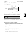
- Toner Supply Motor On Time Calculation The toner motor on time is decided by the following factors (point "5" on the
flow chart).
• ∆VT (this is VT - VTREF)
• Copy volume counter
• Paper size
The copy volume counter (CVOL) is determined as follows:
0: 1-9 consecutive copies have been made with ∆VT > 0
1: 10-19 consecutive copies have been made with ∆VT > 0
If ∆VT becomes negative at any time (i.e., there is enough toner), CVOL
decreases to 0.
The toner motor on times are shown below.
0 < ∆VT <= 0.22,
CVOL = 0
0 < ∆VT <= 0.22,
CVOL = 1
∆VT > 0.22,
CVOL = 0 or 1
Paper Length
< 250 mm
Paper Length
250 - 400 mm
Paper Length
> 400 mm
0.5
0.7
0.9
1.0
1.3
1.8
1.0
1.3
1.8
NOTE: The toner supply amount is 0.1 g for 0.5 s
4.5.6 Toner Supply in Abnormal sensor Conditions
There are two service codes for a TD sensor error. These SC conditions can
be cleared by turning the main switch off and on again. After doing this, the
machine automatically performs the TD sensor initial setting.
1. TD sensor error 1
When the TD sensor output voltage (VT) is less than 0.5 V, 20 seconds after
the TD sensor initial setting has been performed, SC390 will be generated.
2. TD sensor error 2
When the TD sensor initial setting is finished, if the TD sensor output voltage
(VT) exceeds the specified range (2 ± 0.2 V), SC393 is generated.
2-37
PCU (PHOTOCONDUCTOR UNIT)
1 August 1996
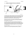
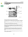
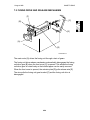
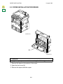
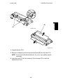
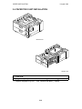
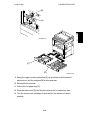
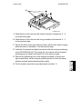
4.5.7 Toner Supply
- Toner Bottle Replenishment Mechanism [E]
[F]
[G]
[C]
[D]
A193D516.wmf
[A]
[H]
[B]
[E]
[F]
[G]
A193D019.wmf
When a toner bottle is placed on the bottle holder unit [A] and pushed back in
completely and the toner bottle holder lever [B] is put back in the original
position, the following happens automatically to allow toner to be supplied to
the development unit.
• The pin [C] on the toner shutter [D] is pulled out (opened) as a result of
the shape of the developer cartridge.
• The cap [E] remaining on the toner bottle is pulled away and kept by the
chuck [F] away from the movement of the roller [G], which rides along the
curved rail behind the toner bottle holder lever.
The toner end detection system determines when to drive the toner bottle
replenishment mechanism (see Toner End Detection). The toner supply
mechanism transports toner from the bottle to the development unit. The
toner bottle has a spiral groove [H] that helps move toner to the development
unit.
When the bottle holder unit is pulled out to add new toner, the following
happens automatically to prevent toner from scattering.
• The chuck releases the toner bottle cap into its proper position.
• The toner shutter shuts the opening as a result of pressure from a spring.
2-38
1 August 1996
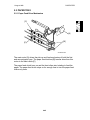
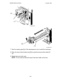
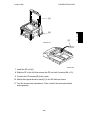
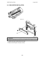
PCU (PHOTOCONDUCTOR UNIT)
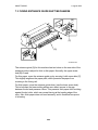
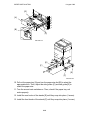
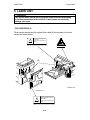
- Toner Supply Mechanism [D]
[C]
[A]
A193D020.wmf
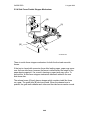
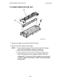
[B]
The toner supply motor [A] drives the toner bottle [B] and the mylar blades
[C]. First, the toner falls down into the toner holder. The toner supply mylar
blades transfer the toner to the slit [D], then the toner falls down into the
development unit through the opening.
2-39
PCU (PHOTOCONDUCTOR UNIT)
1 August 1996
- Toner Near End/End Detection Copy
Has the
copy job been
finished?
VT detection
Yes
4
No
V TREF
determination
VT > VTE – 0.2
No
Yes
VTE determination
Is this 5 or more
times in a row?
VT – VTREF = ∆VT
Yes
No
1
No
VT > VTE
Is this the 15th
time in a row?
Yes
Yes
No
Toner supply motor
on time calculation
∆V T > 0
No
VT detection
Yes
2
Have 30 copies
been made?
Yes
No
No
VT > VTE
Yes
Toner supply motor
on time calculation
Toner near end
3
No
Have 50 copies
been made?
Yes
Toner End
A193D541.wmf
2-40
1 August 1996
PCU (PHOTOCONDUCTOR UNIT)
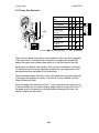
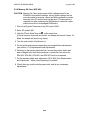
There is no toner end sensor in this machine. Instead, toner end/near-end is
detected using the TD sensor output data.
The machine checks for toner near end/end every copy. If toner near-end or
toner end is detected during the copy job, it is also checked after finishing the
copy job. To detect toner near end, the machine first decides the toner end
reference voltage (VTE) based on the TD sensor initial setting and the
humudity sensor output. Then, the machine compares VTE with the TD
sensor output voltage (VT): this is point 1 on the flow chart.
During a copy job:
If VT is greater than VTREF (this means the amount of toner in the
development unit is low), the machine supplies toner (see Toner Supply).
If toner concentration is still low after 30 copies (point 2 on the flow chart), the
machine checks for a toner near end condition (if VT is greater than VTE,
there is a near end condition).
If toner concentration is still low 50 copies after toner near-end was
determined (point 3 on the flow chart), the machine detects a toner end
condition.
After a copy job:
When the machine detects that toner concentration is low, after the copy job
is finished, the machine decreases VTE by 0.2 V and compares the new VTE
with VT ("4" on the flow chart). If the toner concentration is still low, the
machine supplies toner. The machine then compares VTE with VT again, and
supplies toner again if VT is too low.
If the toner concentration is still too low after supplying toner 15 times ("5" on
the flow chart), the machine detects a toner near-end condition.
If toner concentration is still low 50 copies after toner near-end was
determined ("3" on the flow chart), the machine detects a toner end condition.
The number of copies between toner near-end and toner end can be
changed with SP 2-213. The default is 50.
- Toner End Recovery If the front cover is opened and closed for more 10 seconds while a toner
near-end/end condition exists and the toner bottle is replaced, the machine
will attempt to recover for 3 minutes using the same procedure as for toner
near-end/end detection after a copy job.
2-41
PCU (PHOTOCONDUCTOR UNIT)
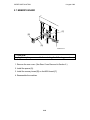
4.6
1 August 1996
DRUM CLEANING AND TONER RECYCLING
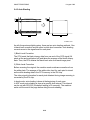
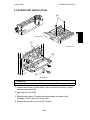
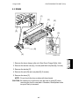
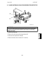
4.6.1 Drum Cleaning
[A]
[B]
A193d010.wmf
5 mm
A193D529.wmf
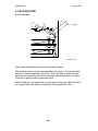
The cleaning blade [A] removes any toner remaining on the drum after the
image is transferred to the paper. This model uses a counter blade system.
The toner remaining on the drum is scraped off by the cleaning blade, and it
falls onto the toner collection coil [B].
To remove the toner and other particles that are accumulated at the edge of
the cleaning blade, the drum turns in reverse for about 5 mm at the end of
every copy job, as shown in the illustration. However, this is not done during
transfer roller cleaning.
2-42
1 August 1996
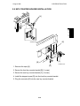
PCU (PHOTOCONDUCTOR UNIT)
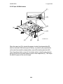
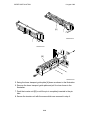
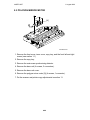
4.6.2 Toner Recycling
[A]
[C]
[B]
A193D016.wmf
Toner which falls onto the toner collection coil [A] is transported to the
recycled toner transport belt [B] at the front of the PCU. The recycled toner
transport belt carries the toner to mixing auger 2 [C] in the development unit.
This toner is mixed with new toner by mixing auger 2 and used again.
2-43
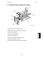
PAPER FEED
1 August 1996
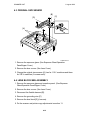
5. PAPER FEED
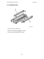
5.1 OVERVIEW
[E]
[A]
[D]
[F]
[B]
[G]
[C]
A193D022.wmf
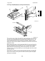
There are two paper trays and a by-pass feed table [A].
The first [B] and second [C] paper trays each hold 250 sheets. The by-pass
feed table can hold 1, 10, or 100 sheets of paper, depending on the paper
size.
The semicircular feed rollers [D] drive the top sheet of paper from the tray to
the registration rollers [E] through the relay rollers [F].
The tray has two corner separators (see [F] in the diagram in the "Paper Lift
Mechanism" section), which allow only one sheet to feed at a time. The
corner seperators, along with the tray’s springs, also serve to set the height
of the paper stack.
When the tray is closed after the paper is loaded, the paper size actuator
located at the front right of the tray pushes the paper size sensor. This
informs the cpu what paper size is loaded in the tray and that the tray is in
place.
There is a relay sensor [G] located between the relay rollers. This sensor is
used for paper jam detection.
2-44
1 August 1996
PAPER FEED
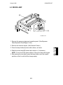
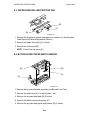
5.2 PAPER TRAY
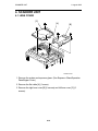
5.2.1 Paper Feed Drive Mechanism
[C]
[A]
[B]
[C]
A193D033.wmf
The main motor [A] drives the pick-up and feed mechanism of both the first
and second paper trays. The paper feed clutches [B] transfer drive from this
motor to the feed rollers [C].
The paper feed clutch turns on and the feed rollers start rotating to feed the
paper. The paper feed clutch stays on for enough time to turn the paper feed
rollers only once.
2-45
PAPER FEED
1 August 1996
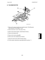
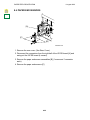
5.2.2 Paper Lift Mechanism
[F]
[D]
[E]
[A]
[C]
A193D024.wmf
[F]
[E]
[B]
When the paper tray [A] is closed after paper is loaded, the release slider [B],
which is mounted on the bottom part of the tray, is pushed by the projection [C]
on the main frame and the release slider comes off the bottom plate hook [D].
Once the release slider comes off, the bottom plate is raised by the pressure
springs [E] and the top sheet pushes up the corner separators [F]. This keeps
the stack of paper at the correct height.
2-46
1 August 1996
PAPER FEED
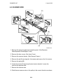
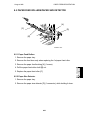
5.2.3 Paper End Detection
[B]
[D]
[A]
[E]
[C]
A193D027.wmf
The paper end feeler [A] is on the same shaft as the paper end actuator [B].
When the paper tray runs out of paper, the paper end feeler drops into the
cutout [C] in the tray bottom plate. The paper end actuator activates the
paper end sensor [D].
The paper end actuator is in contact with the lever [E]. When the tray is
drawn out, the lever turns as shown by the arrow in the figure. Then the lever
pushes up the actuator. As a result, the feeler rotates upwards. This
mechanism is necessary to prevent the feeler from getting damaged by the
paper tray body.
2-47
PAPER FEED
1 August 1996
5.2.4 Side Fence Double Stopper Mechanism
[B]
[A]
[B]
[A]
A193D026.wmf
There is a side fence stopper mechanism for both the front and rear side
fences.
If the tray is closed with excessive force after loading paper, paper may come
over the rear side fence, because the fence is deformed by the weight of the
paper leaning against it. As a result, skewing or paper jams may occur. To
prevent this, a side fence stopper mechanism has been added to the rear
side fence also.
The release levers [A] each have a stopper which contains teeth like those
on a gear. The guide rails [B] also have teeth. When the release lever is
pushed, the gear teeth release each other and the side fences can be moved.
2-48
1 August 1996
PAPER FEED
5.2.5 Paper Size Detection
SW
1
2
3
4
●
●
●
●
●
❍
●
❍
●
●
❍
❍
❍
❍
❍
❍
Size
A3, F( 81/2"x13" )
A4 Lengthwise
A4 Sideways
A5 Sideways,
11"x17"
[A]
B4, 81/2"x14"
B5 Sideways,
81/2"x11"
B5 Lengthwise,
11"x81/2"
* (Asterisk)
[B]
A193D025.wmf●:
❍ ● ❍ ❍
❍ ❍ ❍ ❍
❍ ❍ ●
❍
❍ ❍ ●
●
ON (Not pushed) ❍: OFF (Pushed)
There are four paper size sensors (microswitches) [A] on the front right plate
of the main frame. The sensors are actuated by a paper size actuator [B]
behind the paper size indicator plate which is on the front right of the tray.
Each paper size has its own actuator, with a unique combination of notches.
To determine which size tray has been installed, the cpu reads which micro
switches have been switched off by the actuator.
The cpu disables paper feed from a tray if the paper size cannot be detected.
If the paper size actuator is broken, or if there is no tray installed, the Add
Paper indicator will light.
When the paper size actuator is at the "*" mark, the paper tray can be set up
to accommodate one of a wider range of paper sizes by using a User Tool. If
the paper size for this position is changed without changing the User Tool
setting, a paper jam will result.
2-49
PAPER FEED
1 August 1996
5.3 BY-PASS FEED
5.3.1 Overview
[A]
A193D022-2.wmf
The by-pass feed table [A] can hold 100 sheets of paper.
This machine does not have a by-pass feed cover sensor. The by-pass feed
indicator is always displayed on the LCD. The Add Paper indicator will light
when the user selects by-pass feed while the by-pass feed table is closed or
if there is no paper on the by-pass feed table.
After the Start key is pressed, the cpu energizes the by-pass feed clutch and
the by-pass feed roller starts to feed paper to the registration roller.
2-50
1 August 1996
PAPER FEED
5.3.2 Paper Feed Mechanism and Paper End Detection
[D]
[C]
[A]
[B]
A193D029.wmf
A193D028.wmf
[E]
A193D033-2.wmf
This machine uses a feed roller and friction pad mechanism, with drive from
the main motor transmitted when the by-pass feed clutch [E] turns on. The
friction pad prevents all but the top sheet from feeding. Therefore, during
paper feed, the top sheet of paper is separated from the stack and fed to the
registration rollers.
Before placing the paper on the by-pass feed table, the user must lower the
by-pass feed table by using the lever [A]. This is to ensure that the paper is
placed between the friction pad [C] and the feed roller [D]. Then, before
starting to copy, it must be put back up to move the paper stack into contact
with the feed roller.
When there is no paper on the by-pass feed table, the paper end feeler [B]
drops into the cutout in the by-pass feed table and the by-pass feed paper
end sensor is activated.
2-51
PAPER FEED
1 August 1996
5.3.3 By-pass Feed Paper Width Detection
[A]
[C]
[B]
A193D030.wmf
[A]
[C]
A193D524.wmf
The paper width switch [A] is a slide switch located inside the by-pass feed
table [B]. It measures the paper width manually. The rear side fence is
connected to the terminal plate [C]. When the side fences are moved to
match the paper width, the terminal plate slides along the wiring patterns on
the detection board. The patterns for each paper width on the paper width
detection board are unique. Therefore, the machine determines which paper
width has been placed in the by-pass feed table by the signal output from the
board. However, the machine will not determine the paper length. For
example, A4 paper set sideways will be determined to be A3 paper.
2-52
1 August 1996
PAPER FEED
5.4 PAPER REGISTRATION
[C]
[B]
[A]
A193D032.wmf
Main motor rotation is transmitted to the registration clutch [A] (located on the
lower registration roller shaft) through the relay gears [B].
The registration sensor [C] is positioned just before the registration rollers.
When the paper leading edge activates the registration sensor, the
registration clutch turns off and the registration rollers stop turning. However,
the relay clutch stays on for a bit longer. This delay allows time for the paper
to press against the registration rollers and buckle slightly to correct skew.
The registration clutch energizes and the relay clutch re-energizes at the
proper time to align the paper with the image on the drum. The registration
and relay rollers feed the paper to the image transfer section.
The registration sensor is also used for paper misfeed detection.
2-53
IMAGE TRANSFER AND PAPER SEPARATION
1 August 1996
6. IMAGE TRANSFER AND PAPER
SEPARATION
[B]
6.1 OVERVIEW
[C]
[A]
A193D538-2.wmf
[D]
[A]
A193D021.wmf
Instead of using a transfer wire and a transfer belt, this machine uses a
transfer roller [A], which touches the drum surface.
The high voltage supply board [B] supplies a positive current (approximately
+15 µA) to the transfer roller. The roller has a high electrical resistance, so it
can hold a high positive electrical potential to attract toner from the drum onto
the paper.
There is a discharge brush [C] after the transfer roller. The curvature of the
drum and the discharge brush helps the paper to drop away from the drum.
The transport fan [D] under the transport guide plate helps to transport the
paper from the transfer area to the fusing unit.
2-54
1 August 1996
IMAGE TRANSFER AND PAPER SEPARATION
6.2 IMAGE TRANSFER AND PAPER SEPARATION
MECHANISM
FGATE: Laser main scan writing start signal
A193D530.wmf
The transfer roller starts rotating at the same time as the main motor starts to
rotate.
1. When the CPU receives the image writing start signal (FGATE signal),
the CPU instructs the power pack to supply +10 µA (low transfer bias) to
the roller. This prevents any positively charged toner on the drum surface
from transferring to the transfer roller.
2. At a certain time after the low transfer bias has been supplied to the
roller, +15 µA (high transfer bias) is applied to the roller to transfer the
toner to the paper.
3. After the trailing edge of the paper has passed through the roller, the transfer
bias turns off. In the multiple copy mode, the transfer bias shifts again to the
low transfer bias.
2-55
IMAGE TRANSFER AND PAPER SEPARATION
1 August 1996
6.3 ROLLER CLEANING
A193D531.wmf
If the paper size is smaller than the printed image, or if a paper jam occurs
during printing, toner may be transferred to the roller surface. To prevent this
toner from transferring to the back side of copies, the transfer roller has to be
cleaned before the next printing run.
During transfer roller cleaning, the power pack supplies a negative cleaning
bias (- 4 µA) to the transfer roller. So, any negatively charged toner on the
transfer roller is then transferred back to the drum. Then a positive cleaning
bias of +10 µA is applied to transfer back to the drum any toner which was
positively charged by the transfer roller.
The machine goes through the cleaning mode in the following conditions:
• After a copy job has been finished.
• At the same time as power on.
• After a printer jam has been cleared.
Also, transfer roller cleaning can be done forcibly by SP2-910.
2-56
1 August 1996
IMAGE TRANSFER AND PAPER SEPARATION
6.4 PAPER SEPARATION AND TRANSPORTATION
[B]
[A]
A193D538.wmf
[A]
A193D021-2
The discharge brush [A] and the curvature of the drum help the paper to drop
away from the drum. The high voltage supply board [B] applies a constant dc
voltage, +2 kV (when feeding from a paper tray), or +2.5 kV (from the duplex
tray) to the discharge brush.
The transport fan helps to transport the paper from the transfer area to the
fusing unit. The transport fan turns on at the same time as the main motor.
Also, the transport fan turns off at the same time as the main motor.
The discharge brush voltage can be adjusted using SP 2-901 (there are
separate settings for the front and rear side, and for the leading edge and
other areas of the paper).
2-57
IMAGE FUSING
1 August 1996
7. IMAGE FUSING
7.1 OVERVIEW
1
10
2
9
3
4
8
5
6
7
A193D034.wmf
The fusing unit consists of the following parts.
1. Fusing thermofuse
6. Pressure lever
2. Hot roller
7. Cleaning roller
3. Fusing thermistor
8. Pressure spring
4. Lower entrance guide
9. Hot roller strippers
5. Pressure roller
10. Fusing lamp
2-58
1 August 1996
IMAGE FUSING
7.2 FUSING DRIVE AND RELEASE MECHANISM
[F]
[C]
[B]
[D]
[A]
[E]
A193D036.wmf
The main motor [A] drives the fusing unit through a train of gears.
The fusing unit drive release mechanism automatically disengages the fusing
unit drive gear [B] when the front cover [C] is opened. This allows the fusing
unit drive gear to rotate freely so that misfed paper can be easily removed.
When the front cover is opened, the actuator plate [D] pulls release wire [E].
The wire pulls the fusing unit gear bracket [F] and the fusing unit drive is
disengaged.
2-59
IMAGE FUSING
1 August 1996
7.3 FUSING ENTRANCE GUIDE SHIFT MECHANISM
[B]
[C]
[A]
A193D539.wmf
The entrance guide [A] for this machine has two holes on the rear side of the
entrance guide to adjust for thick or thin paper. Normally, the upper screw
hole [B] is used.
For thin paper, move the entrance guide up by securing it with screw hole [C].
This slightly lengthens the paper path, which prevents the paper from
creasing in the fusing unit.
For thick paper, move the entrance guide down (use the lower screw hole).
This is because the lower setting allows more direct access to the gap
between the hot and pressure rollers. This prevents thick paper from buckling
against the hot roller, which can cause blurring at the leading edge of the
copy. Also, thick paper does not bend as easily, and is therefore less prone
to creasing.
2-60
1 August 1996
IMAGE FUSING
7.4 PRESSURE ROLLER
[B]
[A]
A193D035.wmf
The pressure roller is made of silicone rubber with teflon tube coating. The
pressure spring [A] constantly applies pressure between the hot roller and the
pressure roller.
The pressure roller can be changed by adjusting the position of the pressure
springs. The middle position [B] is the normal setting. The upper position
increases the pressure and this prevents insufficient fusing.
7.5 CLEANING MECHANISM
[B]
[A]
A193D537.wmf
The cleaning roller [A] is always in contact with the pressure roller [B]. It
collects toner and paper dust adhering to the surface of the pressure roller.
This is because the cleaning roller is made of metal and collects adhering
matter more easily than the pressure roller (which has a teflon coating).
2-61
IMAGE FUSING
1 August 1996
7.6 FUSING TEMPERATURE CONTROL
(° C )
200
180
165
150
100
50
S ta n d by
M a in S W O N
A193D525.wmf
When the main switch turns on, the CPU checks the ac frequency for 500
ms. Then the CPU turns on the fusing lamp. When the thermistor detects the
stand-by temperature (165 °C), the machine can start to print. When the
thermistor detects the operating fusing temperature (180 °C), the CPU
maintains this temperature using phase control.
Phase control is the only type of fusing control in this machine.
7.7 OVERHEAT PROTECTION
If the hot roller temperature becomes greater than 230°C, the CPU cuts off
the power to the fusing lamp. At this time, SC543 will be generated.
Even if the thermistor overheat protection fails, there is a thermofuse in series
with the common ground line of the fusing lamp. If the temperature of the
thermofuse reaches 169°C, the thermofuse opens, removing power from the
fusing lamp. At this time, the copier stops operating.
2-62
1 August 1996
ENERGY SAVER MODES
8. ENERGY SAVER MODES
8.1 OVERVIEW
When the machine is not used, the energy saver function reduces power
consumption by decreasing the fusing temperature.
This machine has three types of energy saver mode as shown below.
1. Auto Energy Saver Mode
2. Auto Shut Off Mode
3. Night Mode
These modes are controlled by the following UP modes.
• System Auto Reset Timer
• Auto Shut Off Timer
• Auto Energy Saver Mode Enable/Disable
• Auto Shut Off Mode Enable/Disable (SP mode only)
The way that the machine operates depends on the combination of installed
equipment (copier only, copier/printer, copier/fax, copier/fax/printer)
2-63
ENERGY SAVER MODES
1 August 1996
8.2 COPIER ONLY
Clear Mode/Energy Saver Key
System Auto Reset Timer
Clear Mode/Energy Saver Key
Original in the DF
DF lifted up
Auto Energy Saver Mode
Energy Saver Level 1 or 2
Fusing lamp to low temperature
Energy Saver LED On
CPU/GAPD On
Auto Shut Off Timer
Stand-by Mode
Main Switch Off
Auto Shut Off Mode
Fusing Lamp Off
Energy Saver LED Off
CPU/GAPD Off
Main Switch On
A193D547.wmf
Entering energy saver mode
The machine enters energy saver level 1 or 2 when one of the following is
done.
• The system auto reset timer runs out.
• The Clear Mode/Energy Saver key is held down for over 1 s
What happens in energy saver modes 1 and 2
When the machine enters energy saver level 1 or 2, the fusing lamp drops to
a certain temperature, depending on the energy saver level selected (UP
mode).
The fusing temperature for energy saver level 1 is 15°C below the fusing
lamp operating temperature, which is set by SP1-105-1 (default: 180 - 15 =
165°C). The fusing temperature for energy saver level 2 is the value set by
SP1-105-2 (default: 140°C for 115V machines, room temperature for 230V
machines).
When the auto shut off timer runs out
The auto shut off timer starts when the machine enters standby mode.
When this timer runs out, the machine enters auto shut off mode and the
main switch turns off automatically. The fusing lamp and all dc supplies
except +5VE turn off.
2-64
1 August 1996
ENERGY SAVER MODES
+5VE is the 5 volt supply for energy saver mode. It saves energy by
supplying +5V power only for the components needed in energy saver mode.
Note that turning the main switch off is the same as entering auto shut off
mode.
Returning to standby mode
- From energy saver level 1 or 2 If one of the following is done, the machine returns to standby mode:
• Pressing the Clear Mode/Energy Saver key
• Placing an original in the ADF
• Lifting up the ADF
The recovery time from energy saver level 1 is about 3 s.
The recovery time from energy saver level 2 is about 10 s (115 V machines)
or about 35 s (230 V machines).
- From auto shut off mode The machine returns to the ready condition when the main switch is turned
on.
The recovery time is less than 30 s for 115V machines, and less than 35 s for
230V machines.
Power Consumption
Mode
Energy Saver
Level 1
Energy Saver
Level 2
Auto Shut Off
Mode
Main
Energy
Fusing System
Switch Saver LED Lamp
+5V
On
On
165°C
On
On
On
140°C
(115V)
Room T
(230V)
On
Off
Off
Off
Off
2-65
Note
The machine returns to standby
mode if the DF is lifted or an
original is placed in the ADF.
The machine returns to standby
mode only if the main switch is
turned on.
ENERGY SAVER MODES
1 August 1996
8.3 COPIER/PRINTER
Clear Mode/Energy Saver Key
System Auto Reset Timer
Clear Mode/Energy Saver Key
Original in the DF
DF lifted up
Auto Energy Saver Mode
Energy Saver Level 1 or 2
Fusing lamp to low temperature
Energy Saver LED On
CPU/GAPD On
System 5V On
Auto Shut Off
Timer
Stand-by Mode
Auto Energy Saver Mode
Clear Mode/Energy Saver Key
Original in the DF
DF lifted up
Main
Switch
Off
Energy Saver Level 3
Fusing Lamp Off
Energy Saver LED On
CPU/GAPD On
System 5V On
Main
Switch
On
Auto Shut Off Mode
Main Switch Off
Fusing Lamp Off
Energy Saver LED Off
CPU/GAPD On
System 5V Off
A193D548.wmf
Entering energy saver mode
The machine enters energy saver level 1 or 2 in the same way as the copier
only configuration.
What happens in energy saver modes 1 and 2
The behaviour of the machine in energy saver levels 1 and 2 is the same as
in the copier only configuration (fusing lamp at low temperature).
However, when the auto shut off timer runs out, the machine enters energy
saver mode level 3 instead of auto shut off mode.
What happens in energy saver level 3
When the machine enters energy saver level 3, the fusing lamp turns off
completely. However, the system 5 volt supply stays on. The recovery time
from this level is the same as for recovery from auto shut off mode. The
machine will print incoming print jobs from a computer.
From energy saver level 3, the machine returns to standby mode in the same
way as from energy saver levels 1 and 2.
2-66
1 August 1996
ENERGY SAVER MODES
Entering auto shut off mode
The machine only enters auto shut off mode if the main switch is turned off.
In this mode, the fusing lamp turns off and the machine will not print anything
coming in from a computer.
Power Consumption
Mode
Energy Saver
Level 1
Energy Saver
Level 2
Energy Saver
Level 3
Auto Shut Off
Mode
Main
Energy
Fusing System
Switch Saver LED Lamp
+5V
On
On
165°C
On
On
On
140°C
(115V)
Room T
(230V)
On
On
On
Off
On
Off
Off
Off
2-67
Off
Note
The machine returns to standby
mode if the DF is lifted or an
original is placed in the ADF.
Data from a PC is printed.
The machine returns to standby
mode only if the main switch is
turned on. Data from a PC is not
printed.
ENERGY SAVER MODES
1 August 1996
8.4 COPIER/FAX, COPIER/PRINTER/FAX
‘
Clear Mode/Energy Saver Key
System Auto Reset Timer
Stand-by Mode
Clear Mode/Energy Saver Key
Original in the DF
DF lifted up
Ringing signal detected
NCU off hook (start of dialing)
Auto Energy Saver Mode
Energy Saver Level 1 or 2
Fusing lamp: Low temp.
Energy Saver LED On
SCP On (System 5V On)
Energy Saver CPU On
(5VE On)
Auto Shut Off
Timer
Auto Energy Saver Mode
Clear Mode/Energy Saver Key
Original in the DF
DF lifted up
Ringing signal detected
NCU off hook (start of dialing)
Energy Saver Level 4
Fusing Lamp Off
Energy Saver LED On
SCP Off (System 5V Off)
Energy Saver CPU On
(5VE On)
Main
Switch
Off
Main Switch On
Main
Switch
Off
Main
Switch
On
Night Mode Level 1
Fusing Lamp Off
Energy Saver LED Off
SCP On (System 5V On)
Energy Saver CPU On
(5VE On)
Ringing signal detected
NCU off hook (start of dialing)
Auto Shut Off Timer
Night Mode Level 2
Fusing Lamp Off
Energy Saver LED Off
SCP Off (System 5V Off)
Energy Saver CPU On
(5VE On)
Main Switch Off
A193D549.wmf
Energy saver mode is more complex in this configuration. This is because
there are two night modes, instead of the auto shut off mode. Night mode
level 2 is similar to auto shut off mode. Night mode level 1 keeps the machine
in a slightly higher state of readiness (the main cpu is active and the system 5
volt supply is on, but the fusing lamp is still off).
Entering energy saver mode
The machine enters energy saver level 1 or 2 in the same way as the copier
only and copier/printer configurations.
2-68
1 August 1996
ENERGY SAVER MODES
What happens in energy saver modes 1 and 2
The behaviour in these levels is the same also (fusing lamp at low
temperature). However, there are two extra cases for leaving energy saver
mode:
• Ringing signal detected
• NCU off-hook (the machine starts to dial a fax number)
If the auto shut off timer runs out while the main switch is still on, the machine
enters energy saver level 4.
What happens in energy saver mode 4
In this mode, the fusing lamp switches off. Also, the system +5V supply
switches off. Only the +5VE supply stays on, so that the machine can monitor
the ADF, the telephone line, and the operation panel.
The machine recovers to standby mode in the same conditions as for level 1
or 2. For example, incoming faxes and printer jobs will be printed. The
recovery time from this level is the same as for recovery from auto shut off
mode.
Entering night mode
If the main switch is turned off while the machine is in standby or energy
saver mode 1 or 2, the machine enters night mode 1.
If the main switch is turned off while the machine is energy saver mode 4, the
machine enters night mode 2.
- Night mode 1 The fusing lamp turns off. However, the system +5V is still supplied to all
components. When the machine detects a ringing signal, the machine
automatically prints the incoming message.
From night mode level 1, the machine goes to night mode level 2 when the
auto shut off timer runs out.
- Night mode 2 The system +5V supply also turns off. However, +5VE (+5V for the energy
saver) is still activated. If the machine detects a ringing signal or off-hook
signal, the machine goes back to night mode level 1. At this time, the system
+5V supply is activated. Then the machine receives the incoming message
and prints it.
The machine leaves night mode and returns to standby mode if the main
switch is turned on.
2-69
ENERGY SAVER MODES
1 August 1996
Power Consumption
Mode
Energy Saver
Level 1
Energy Saver
Level 2
Energy Saver
Level 4
Night Mode
Level 1
Main
Energy
Fusing System
Switch Saver LED Lamp
+5V
On
On
165°C
On
On
On
140°C
(115V)
Room T
(230V)
On
On
On
Off
On
Off
Off
Off
On
Off
Off
Off
Off
Night Mode
Level 2
2-70
Note
The machine returns to standby
mode if the DF is lifted or an
original is placed in the ADF.
Incoming faxes and data from a
PC are printed.
Incoming faxes are printed, and
faxes can be sent. However, PC
data is not printed. For copying,
the machine returns to standby
mode only if the main switch is
turned on.
If an incoming call (ringing signal)
is detected, or if the user tries to
send a fax, the machine goes
into Night Mode Level 1. PC data
is not printed. For copying, the
machine returns to standby mode
only if the main switch is turned
on.
1 August 1996
ENERGY SAVER MODES
8.5 ENERGY SAVER CONTROL
The block diagram on the next page shows the relationship between the
power supply signals and the command signals for energy saver mode.
There are two CPUs for energy saver mode. One is the CPU/GAPD (Gate
Array Power Drive) on the BICU board and the other is the Energy Saver
CPU on the FCU board.
The +5VE supply is for energy saver mode, and it is always supplied to the
machine. The +5V supply is shut down in some energy saver modes.
Copier configuration
When either the Clear Modes/Energy Saver Mode key is pressed or the
system auto reset timer runs out, the GAPD turns on the Energy Saver LED
and requests the main CPU to reduce the fusing temperature.
When the auto shut off timer runs out, the GAPD turns off the main switch
using the SW_TRG signal. Then IC 11 on the BICU board sends a signal to
the PSU, and the PSU shuts down the +5V, +12V, -12V, and +24V supplies
and cuts the ac power for the fusing lamp.
Copier/printer configuration
The GAPD controls the energy saver function, as in the copier configuration.
When the auto shut off timer runs out, the GAPD keeps the Energy Saver
LED on but requests the main CPU to cut the fusing lamp power.
When the main switch has been turned off manually, the CPU requests the
PSU to shut down the +5V, +12V, -12V, and +24V supplies.
Fax configurations (Copier/fax and Copier/fax/printer)
The Energy Saver CPU monitors the Clear Modes/Energy Saver Mode key,
and controls the Energy Saver LED. When either the Clear Modes/Energy
Saver Mode key is pressed or the system auto reset timer runs out, the
Energy Saver CPU turns the Energy Saver LED on and requests the copier
main CPU to reduce the fusing temperature. When the auto shut off timer
runs out, the Energy Saver CPU keeps on the Energy Saver LED, but
requests the copier main CPU to cut the fusing lamp power. Then the CPU
instructs the PSU to shut down the +5V, +12V, -12V, and +24V supplies.
When the main switch has been turned off manually (night mode), the Energy
Saver CPU turns off the Energy Saver LED, and the fusing lamp goes off.
When the CPU detects one of the energy saver recovery conditions, it
requests the PSU to supply all dc supplies using the /RTRG signal.
2-71
ENERGY SAVER MODES
1 August 1996
- Block Diagram Application
I/F
Operation
Panel I/F
+5VE
+5VE
+5VE
FCU
+5VE
Main Switch
SW_OUT
+5VE
SW_IN
Hook
+24V
TRG
IC11
HIC
Ring
NCU
/SW_TRG
+24VE
+5VE
+5VE
10k
Energy
Saver
CPU
/SW_ON
+5V +5V
/RTRG
+5V
+5V
Energy
Saver
key
+5V
/OP_KEY
/OP
KEY
SCP
/SN_ON
/SW_ON
GOPC
DC/DC
/EX/FCU
+5VE
CPU/
GAPD
+5V
+5VE
+5V
/OP_LED
+5V
+5V
Energy Saver LED
Printer Controller
+5VE
+5VE
CPU
+5V
Operation Panel
/SN_ON
BICU
+5VE
+5VE
Original
Set
Sensor
AC/DC
AC
Switch
+5V
+5VE
DF
Position
Sensor
+5V
+5V
+12V
+5V
TE6251
-12V
AC/
DC
+24V
IOCSS
+5VE
+5V
PSU
+5V
+5V for energy saver mode
+5V for system power
A193D533.wmf
2-72
1 August 1996
ENERGY SAVER MODES
8.6 ENERGY SAVER TIMING CHARTS
1. Auto Energy Saver mode: On
Auto Shut Off mode: On
- Copier Configuration System Auto Reset Timer
(0 ~ 180 s)
Auto Shut Off Timer
(5 ~ 120 min.)
On
Energy Saver LED
Off
On
Main Switch
Off
Energy saver level 1
Energy saver level 2
Power
Consumption
1.5 W (Copier)
A193D532.wmf
- Copier + Fax and Copier + Fax + Printer Configurations -
System Auto Reset Timer
(0 ~ 180 s)
Auto Shut Off Timer
(5 ~ 120 min.)
On
Energy Saver LED
Main
Switch
Off
On
Off
Energy saver level 1
Energy saver level 2
Power
Consumption
3.5 W (C + F)
25 W (C + P)
28 W (C + F + P)
A193D515.wmf
2-73
ENERGY SAVER MODES
2. Auto Energy Saver mode: Off
1 August 1996
Auto Shut Off mode: On
- All configurations System Auto Reset
Timer
(0 ~ 180 s)
Auto Shut Off Timer
(5 ~ 120 min.)
On
Energy Saver
LED
Off
On
Main Switch
Off
1.5 W (Copier and Copier + Printer)
3.5 W (Copier + Fax)
28 W (Full options)
Power
Consumption
A193D514.wmf
2-74
1 August 1996
PAPER EXIT
9. PAPER EXIT
[A]
[B]
A193D039.mwf
The copy from the fusing unit goes either upwards to deliver the copy paper
to the face down tray, or straight through to the face up tray, depending on
the junction gate [A].
The junction gate solenoid [B] operates the junction gate. Usually, the
junction gate is off and the copy goes up to the face down copy tray. When
the junction gate solenoid is energized, the junction gate is opened. Then the
copy goes through to the face up copy tray.
2-75
SECTION 3
INSTALLATION
1 August 1996
INSTALLATION REQUIREMENTS
1. INSTALLATION REQUIREMENTS
1.1 ENVIRONMENT
1. Temperature Range:
10 OC to 30 OC (50 OF to 86 OF)
2. Humidity Range:
15 % to 90 % RH
3. Ambient Illumination:
Less than 1,500 lux (Do not expose to direct
sunlight.)
4. Ventilation:
Room air should turn over at least 30
m3/hr/person
5. Ambient Dust:
Less than 0.10 mg/m3 (2.7 x 10 -6 oz/yd3)
6. Avoid an area which is exposed to sudden temperature changes. This
includes:
1) Where it will not be directly exposed to cool air from an air conditioner.
2) Where it will not be directly exposed to reflected heat from a heater.
7. Do not place the machine in an area where it will be exposed to corrosive
gasses.
8. Do not install the machine at any location over 2,000 m (6,500 ft.) above
sea level.
9. Place the copier on a strong and level base. (Inclination on any side
should be no more than 5 mm.)
10. Do not place the machine where it may be subjected to strong vibrations.
1.2 MACHINE LEVEL
1. Front to back:
Within 5 mm (0.2") of level
2. Right to left:
Within 5 mm (0.2") of level
3-1
INSTALLATION REQUIREMENTS
1 August 1996
1.3 MINIMUM SPACE REQUIREMENTS
Place the copier near the power source, providing clearance as shown:
C
15 cm (5.9")
11 cm (4.4")
10 cm (4.0")
55 cm (21.7")
10 cm (4.0")
58 cm (22.9")
D
B
A
A: In front:
B: Left:
C: To rear:
D: Right:
A193I512.wmf
Over 75 cm (29.6")
Over 34 cm (13.4")
Over 1 cm (0.4")
Over 31 cm (12.2")
NOTE: The 75 cm recommended for the front space is for pulling out the
paper tray only. If an operator stands at the front of the copier, more
space is required.
1.4 POWER REQUIREMENTS
CAUTION
1. Make sure that the wall outlet is near the copier and easily accessible.
Make sure the plug is firmly inserted in the outlet.
2. Avoid multi-wiring.
3. Be sure to ground the machine.
1. Input voltage level: 120 V, 60 Hz: More than 10 A
220 V ~ 240 V, 50 Hz/60 Hz: More than 6 A
2. Permissible voltage fluctuation: 10 %
3. Do not set anything on the power cord.
3-2
1 August 1996
COPIER INSTALLATION
2. COPIER INSTALLATION
2.1 ACCESSORY CHECK
Check the quantity and condition of the accessories in the box against the
following list:
No.
1
2
3
Description
Operating Instructions
User Survey Card (-17 machine only)
NECR
3-3
Q’ty
2
1
1
COPIER INSTALLATION
1 August 1996
2.2 COPIER INSTALLATION PROCEDURE
A193I500.wmf
[A]
A193I501.wmf
CAUTION
Unplug the copier power cord before starting the following procedure.
1. Remove the tapes on the exterior of the copier.
2. Open the front cover [A].
3. Remove the tapes inside the copier.
3-4
1 August 1996
COPIER INSTALLATION
[B]
[A]
A193I514.wmf
A193I515.wmf
4. Unpack the new PCU.
5. Remove 2 clamps [A] and drum protection sheet [B] from the new PCU.
NOTE: Do not touch the photoconductor. If you do, copy quality may be
abnormal.
6. Insert the new PCU into the machine. Push the new PCU in until the
release lever locks.
3-5
COPIER INSTALLATION
1 August 1996
[A]
A193I502.wmf
[B]
[C]
A193I503.wmf
7. Peel the sealing tape [A] off the development unit to install the developer.
8. Raise the toner bottle holder lever [B] and pull the toner bottle holder [C]
out.
9. Shake the toner bottle well.
NOTE: Do not remove the bottle cap of the toner bottle at this time.
3-6
1 August 1996
COPIER INSTALLATION
[C]
[A]
[D]
[H]
[B]
A193I504.wmf
[E]
[F]
[G]
A193I505.wmf
10. Unscrew the bottle cap [A] and insert the bottle into the holder [B].
NOTE: Do not open the inner bottle cap [C].
11. Reposition the holder and press down the holder lever [D] to secure the
bottle.
12. Install the optional platen cover if required:
1) Install two stud screws on the top cover.
2) Position the platen cover bracket on the stud screws and slide it to the
left.
13. Pull the paper tray [E] out and turn the paper size dial [F] to select the
appropriate size. Adjust the side guides [G] and end guide [H] to match
the paper size.
14. Turn the ac and main switches on. The machine automatically performs
TD sensor initial setting. Then, check the copy quality and copying
functions.
NOTE: Do not turn the ac and main switches off or open any covers
during the TD sensor initial setting.
3-7
COPIER INSTALLATION
1 August 1996
2.3 AUTO DOCUMENT FEEDER INSTALLATION
A628I501.wmf
[G]
[A]
A628I500.wmf
[F]
[B]
[E]
[H]
[D]
[C]
A628I502.wmf
CAUTION
Unplug the copier power cord before starting the following procedure.
NOTE: When installing the DF, use the tool [A] in the accessory bag or a
usual screw driver.
1. Unplug the document feeder. Then, remove all tapes.
2. Remove the left scale [B] (2 screws).
3. Place the DF exposure glass [C] on the glass holder.
4. Peel off the backing [D] of the double side tape attached to the rear side of
the scale guide [E], then install the scale guide (2 screws removed in step 2).
5. Attach the original size decal [F] to the scale guide.
NOTE: Place the decal at the rear edge, and the left side flush with the
scale paper guide [G], as shown.
6. Install the stud screws [H] for the DF on the copier.
3-8
1 August 1996
COPIER INSTALLATION
[A]
[B]
A628I503.wmf
[C]
A628I505.wmf
7. Install the DF unit [A].
8. Slide the DF to the left, then secure the DF unit with 2 screws (M4 x 10).
9. Connect the I/F harness [B] to the copier.
10. Attach the original direction decal [C] to the DF table as shown.
11. Turn the ac and main switches on. Then, check if the document feeder
works properly.
3-9
COPIER INSTALLATION
1 August 1996
2.4 PAPER TRAY UNIT INSTALLATION
G697I500.wmf
G697I501.wmf
CAUTION
Unplug the copier power cord before starting the following procedure.
1. Unpack the paper tray unit. Then, remove the tapes (7 tapes).
3-10
1 August 1996
COPIER INSTALLATION
[D]
[C]
[B]
G697I503.wmf
[A]
G697I502.wmf
[E]
[G]
[F]
G697I504.wmf
2. Place the copier on the paper tray unit [A] with the pegs [B] fitting into the
copier’s peg holes.
3. Remove the copier’s second paper tray [C].
4. Secure the knob screw [D].
5. Push the copier’s second paper tray back into the copier.
6. Remove the connector cover [E].
7. Connect the paper feed unit harness [F] to the copier.
8. Reinstall the connector cover.
9. Secure the joint bracket [G] to the copier (2 screws).
NOTE: Do not pinch the harness.
3-11
COPIER INSTALLATION
1 August 1996
[D]
[A]
[B]
[C]
G697I505.wmf
[E]
[F]
[E]
[F]
G697I506.wmf
10. Pull out the paper tray [A] and turn the paper size dial [B] to select the
appropriate size. Then, adjust the side guides [C] and end guide [D] to
match the paper size.
11. Turn the ac and main switches on. Then, check if the paper tray unit
works properly.
12. Install the rear hooks of the stands [E] until they snap into place (1 screw).
13. Install the front hooks of the stands [F] until they snap into place (1 screw).
3-12
1 August 1996
COPIER INSTALLATION
2.5 DUPLEX UNIT INSTALLATION
[A]
G694I500.wmf
[C]
G694I508.wmf
[B]
[D]
G694I502.wmf
CAUTION
Unplug the copier power cord before starting the following procedure.
1. Unpack the inverter unit and duplex unit and remove the tapes (7 tapes)
and two knob screws [A].
2. Open the front cover [B].
3. Slide the two hinges [C] inward and remove them as shown in the
illustration. Then, remove the front cover.
4. Remove the inverter unit cover [D] (1 screw).
3-13
COPIER INSTALLATION
1 August 1996
[A]
G694I503.wmf
G694I504.wmf
[B]
G694I505.wmf
5. Swing the lower transport guide plate [A] down as shown in the illustration.
6. Remove the lower transport guide plate and pull it out as shown in the
illustration.
7. Push the inverter unit [B] in until the pin is completely inserted in the pin
hole.
8. Secure the inverter unit with the screw which was removed in step 4.
3-14
1 August 1996
COPIER INSTALLATION
[B]
[A]
G694I506.wmf
[C]
[D]
G694I507.wmf
9. Swing the upper inverter guide plate [A] up as shown in the illustration
and secure it with the magnets [B] at front and rear.
10. Reinstall the front cover.
11. Pull out the 1st paper tray [C].
12. Push the duplex unit [D] into the place where the 1st paper tray was.
13. Turn the ac and main switches on and check if the duplex unit works
properly.
3-15
COPIER INSTALLATION
1 August 1996
2.6 1-BIN SORTER INSTALLATION
A629I500.wmf
[A]
A629I501.wmf
CAUTION
Unplug the copier power cord before starting the following procedure.
1. Unpack the copy tray and remove the tape.
2. Remove the left upper cover [A] (1 screw).
3-16
1 August 1996
COPIER INSTALLATION
[A]
[B]
[D]
A629I502.wmf
[C]
[E]
[H]
[F]
[G]
A629I503.wmf
3. Insert the hooks on the 1-bin sorter tray into the slots in the sorter unit [A].
4. Hook the clips on the 1-bin sorter unit onto the stud pins [B] on the copier.
5. Insert the pins [C] into the pin holes in the copier. Make sure to rest the
1-bin sorter tray on the tray support [D].
NOTE: Do not pinch the I/F harness [E].
6. Open the left cover [F] and secure the unit (2 screws [G]).
NOTE: Use the screw which was removed in step 2 and the other screw
which is packed.
7. Couple the I/F cable connector with the copier.
8. Install the connector cover [H].
9. Turn the ac and main switches on and check if copies are delivered to the
1-bin sorter properly.
3-17
COPIER INSTALLATION
1 August 1996
2.7 MEMORY BOARD
[C]
[B]
[A]
A193I041.wmf
CAUTION
Unplug the copier power cord before starting the following procedure.
1. Remove the rear cover. (See Rear Cover Removal in Section 6.)
2. Install the spacer [A].
3. Install the memory board [B] on the MSU board [C].
4. Reassemble the machine.
3-18
1 August 1996
COPIER INSTALLATION
2.8 KEY COUNTER HOLDER INSTALLATION
[A]
[E]
A193I043.wmf
[C]
[B]
A193I044.wmf
[D]
1. Remove the caps [A].
2. Secure the front key counter bracket [B] (1 screw).
3. Secure the rear key counter bracket [C] (1 screw).
4. Install the stepped screw [D] into the front key counter bracket.
5. Plug the connector [E] into the rear key counter bracket.
3-19
COPIER INSTALLATION
1 August 1996
[A]
[B]
[C]
[D]
A193I506.wmf
[E]
[G]
[F]
A193I045.wmf
6. Hold the key counter plate nuts [A] on the inside of the key counter
bracket [B] and insert the key counter holder [C].
7. Secure the key counter holder to the bracket (2 screws).
8. Install the key counter cover [D] (2 screws).
9. Connect the connector of the key counter holder.
10. Hook the key counter holder assembly [E] onto the stepped screw [F].
11. Secure the key counter holder assembly with a screw [G].
3-20
1 August 1996
COPIER INSTALLATION
2.9 ANTI-CONDENSATION HEATER INSTALLATION
[A]
[E]
[B]
[F]
[C]
[D]
A193I511.wmf
[G]
A193I510.wmf
CAUTION
Unplug the copier power cord before starting the following procedure.
1. Remove the rear cover and lens cover. (See Rear Cover Removal and
Lens Cover Removal in Section 6.)
2. Hook both ends of the heater [A] onto the clips [B].
3. Push the heater into the two clips.
4. Slide the heater to the left until it clicks into place. Fit the harness [C] into
the clip [D].
NOTE: Leave the clip out to prevent the heater from slipping off.
5. Insert the connector [E] into the hole.
6. Secure the inner cover [F].
7. Couple the connector coming down from the hole with another connector
[G] coming up from the printer.
NOTE: Tell the customer that even when the copier’s main switch is
turned off, the copier power cord should be plugged in.
Otherwise, the heater will not function.
3-21
COPIER INSTALLATION
1 August 1996
2.10 TRAY HEATER
[C]
[B]
[A]
A193I507.wmf
CAUTION
Unplug the copier power cord before starting the following procedure.
1. Remove the 2nd paper feed tray.
2. Install the clamp [A] on the base. Then, install the tray heater [B] (1
screw).
3. Connect the connector [C] of the heater to the copier’s connector [D],
which is on the rear frame.
4. Reassemble the machine.
5. Check the printer side-to-side registration (2nd paper tray).
NOTE: Tell the customer that even when the copier’s main switch is
turned off, the copier power cord should be plugged in.
Otherwise, the tray heater will not function.
3-22
1 August 1996
COPIER INSTALLATION
2.11 TRAY HEATER (OPTIONAL PAPER TRAY UNIT)
[B]
[A]
[C]
A193I508.wmf
CAUTION
Unplug the copier power cord before starting the following procedure.
1. Remove the upper paper tray [A] (4 screws).
2. Remove the rear cover [B] (2 screws).
3. Install the tray heater [C] (1 screw)
3-23
COPIER INSTALLATION
1 August 1996
[H]
[F]
[G]
[D]
[E]
A193I509.wmf
4. Install 3 clamps [D]
5. Install the interface board [E], and connect the tray heater harness [F] to
the interface board. Then, clamp the harness as shown in the illustration.
6. Connect the interface harness [G] to the motor [H] and interface board.
7. Reassemble the machine.
8. Check the printer side-to-side registration (3rd and 4th tray).
NOTE: Tell the customer that even when the copier’s main switch is
turned off, the copier power cord should be plugged in.
Otherwise, the tray heater will not function.
3-24
SECTION 4
SERVICE TABLES
1 August 1996
SERVICE REMARKS
1. SERVICE REMARKS
1.1 GENERAL CAUTION
Do not turn off the main switch while any of the electrical components are
active. Doing so might cause damage to units, such as the PCU, when they
are pulled out of or put back into the copier.
1.2 PCU
The PCU consists of the OPC drum, development unit, charge roller unit, and
cleaning unit. Follow the cautions below when handling a PCU.
1. Never touch the drum surface with bare hands. When the drum surface is
touched or becomes dirty, wipe it with a dry cloth or clean it with wet
cotton. Wipe with a dry cloth after cleaning with the cotton.
2. Never use alcohol to clean the drum; alcohol dissolves the drum surface.
3. Store the PCU in a cool, dry place away from heat.
4. Take care not to scratch the drum as the drum layer is thin and is easily
damaged.
5. Never expose the drum to corrosive gases such as ammonia gas.
6. Never shake the PCU. Doing so may cause toner and/or developer to
spill out.
7. Do not bend the PCU. Doing so may cause toner and/or developer to spill
out.
8. Dispose of used PCUs in accordance with local regulations.
9. Do not touch the charge roller with bare hands. Oil stains may cause
black bands on copies due to excessive drum charge.
10. Prevent the charge roller from being exposed to dusty air. Dust on the
charge roller may cause white spots on copies due to insufficient drum
charge.
11. Never use alcohol or water to clean the drum charge roller. Alcohol or
water corrode its surface. Wipe with a dry cloth.
4-1
SERVICE REMARKS
1 August 1996
1.3 TRANSFER ROLLER UNIT
1. Never touch the transfer belt surface with bare hands.
2. Take care not to scratch the transfer roller as the surface is easily
damaged.
1.4 SCANNER UNIT
2. Clean the exposure glass with alcohol or glass cleaner to reduce the
amount of static electricity on the glass surface.
3. Use a cotton pad with water or a blower brush to clean the mirrors and
lens.
4. Do not bend or crease the exposure lamp flat cable.
5. Do not disassemble the lens unit. Doing so will throw the lens and the
copy image out of focus.
6. Do not turn any of the CCD positioning screws. Doing so will throw the
CCD out of position.
1.5 LASER UNIT
1. Do not loosen the screws that secure the LD drive board to the laser
diode casing. Doing so would throw the LD unit out of adjustment.
2. Do not adjust the variable resistors on the LD unit, as they are adjusted in
the factory.
3. The polygon mirror and F-theta mirror are very sensitive to dust. Never
open the optical housing unit.
4. Do not touch the glass surface of the polygon mirror motor unit with bare
hands.
1.6 FUSING UNIT
1. After installing the fusing thermistor, make sure that it is in contact with
the hot roller and that it rotates freely.
2. Be careful not to damage the edges of the hot roller strippers or their
tension springs.
3. Do not touch the fusing lamp and rollers with bare hands.
4. Make sure that the fusing lamp is positioned correctly and that it does not
touch the inner surface of the hot roller.
4-2
1 August 1996
SERVICE REMARKS
1.7 PAPER FEED
1. Do not touch the surface of the pick-up, feed, and separation rollers.
2. The side fences and end fences of the paper tray must be positioned
correctly to align with the actual paper size to avoid paper misfeeds.
1.8 OTHERS
1. The TD sensor initial setting is performed automatically after installing the
new PCU and closing the front cover. Never open the front cover or turn
off the main switch during this time. The main motor stops when the initial
setting has finished.
2. The toner bottle should be replaced while the main switch is on.
3. If the optional tray and anti-condensation heaters have been installed,
keep the copier power cord plugged in, even when the copier main switch
is turned off. This keeps the heaters energized.
4-3
SERVICE PROGRAM MODE
1 August 1996
2. SERVICE PROGRAM MODE
2.1 SERVICE PROGRAM MODE OPERATION
The service program (SP) mode is used to check electrical data, change
modes, and adjust values.
2.1.1 Service Program Access Procedure
A193M505.wmf
1) How to enter the SP mode
Press the following keys in sequence.
→ → → → Hold the key for more than 3 seconds.
2) How to exit SP mode
Press the key or exit key three times.
2.1.2 Accessing Copy Mode from within an SP Mode
1. Press the Interrupt key.
2. Select the appropriate copy mode and make trial copies.
3. To return to the SP mode, press the Interrupt key again.
4-4
1 August 1996
SERVICE PROGRAM MODE
2.1.3 How to select the program number
Program numbers are composed of two or three levels.
A193M506.wmf
To input the required program number, select each program level in
sequence.
1. Select the 1st level program number at the numeric key pad and press
the key or OK key.
NOTE: The 1st level program number can be selected using the arrow
keys or Prev key or Next key.
2. Select the 2nd level program number at the numeric key and press the
key or OK key.
NOTE: The 2nd level program number can be selected using the arrow
keys or Prev key or Next key.
3. If there any are third level programs in the SP mode, they can be selected
the same way as the 1st and 2nd level SP modes.
NOTE: The 3rd level program number can be selected using the arrow
keys or Prev key or Next key.
2.1.4 To Input a Value or Setting for an SP Mode
1. Enter the required program mode as explained above.
2. Enter the required setting using the numeric keys, then press the key
or OK key.
NOTE: If you forget to press the key or OK key, the previous value
remains.
3. Exit SP mode.
4-5
SERVICE PROGRAM MODE
1 August 1996
2.2 SERVICE PROGRAM MODE TABLES
2.2.1 Main SP Mode Table
NOTE: 1) In the Function column, comments are in italics.
2) In the Settings column, the default value is in bold letters.
3) An asterisk " * " after the mode number means that this mode is
stored in the NVRAM. If the RAM is reset, all these SP modes will
return to their factory settings.
Mode No.
Class
Class 3
1 and 2
Leading Edge
Registration
(Normal
copying, and
1
duplex 1st
side)
1-001 *
2
1
1-002 *
2
3
Function
Adjusts the printing leading edge
registration using the Trimming Area
Pattern (SP5-902, No.10).
Use the •/∗ key to toggle between + and -.
The specification is 3 ±2 mm. See
"Replacement and Adjustment - Copy
Image Adjustments" for details.
Leading Edge Adjusts the printing leading edge
Registration
registration using the Trimming Area
(Duplex: 2nd Pattern (SP5-902, No.10).
side)
Use the •/∗ key to toggle between + and -.
The specification is 3 ±2 mm. See
"Replacement and Adjustment - Copy
Image Adjustments" for details.
Side-to-Side
Adjusts the printing side-to-side
Registration
registration from the 1st paper feed
(1st paper
station using the Trimming Area Pattern
feed)
(SP5-902, No.10).
Use the •/∗ key to toggle between + and -.
The specification is 2 ±1.5 mm. See
"Replacement and Adjustment - Copy
Image Adjustments" for details.
Side-to-Side
Adjusts the printing side-to-side
Registration
registration from the 2nd paper feed
(2nd paper
station using the Trimming Area Pattern
feed)
(SP5-902, No.10).
Use the •/∗ key to toggle between + and -.
The specification is 2 ±1.5 mm.
Side-to-Side
Adjusts the printing side-to-side
Registration
registration from the 3rd paper feed
(3rd paper
station using the Trimming Area Pattern
feed: Option
(SP5-902, No.10).
PFU tray 1)
Use the •/∗ key to toggle between + and -.
The specification is 2 ±1.5 mm.
4-6
Settings
+9 ~ -9
0.1 mm/step
+ 0.0 mm
+12.5 ~ -12.5
0.1 mm/step
+ 0.0 mm
+9 ~ -9
0.1 mm/step
+ 0.0 mm
+9 ~ -9
1 mm/step
+ 0.0 mm
+9 ~ -9
1 mm/step
+ 0.0 mm
1 August 1996
SERVICE PROGRAM MODE
Mode No.
Class
Class 3
1 and 2
Side-to-Side
Registration
(4th paper
4
feed: Option
PFU tray 2)
1-002 *
5
6
1
1-003 *
2
1-006 *
1-007 *
1
1-105 *
2
Function
Adjusts the printing side-to-side
registration from the 4th paper feed
station using the Trimming Area Pattern
(SP5-902, No.10).
Use the •/∗ key to toggle between + and -.
The specification is 2 ±1.5 mm.
Side-to-Side
Adjusts the printing side-to-side
Registration
registration from the by-pass feed table
(By-pass feed) using the Trimming Area Pattern
(SP5-902, No.10).
Use the •/∗ key to toggle between + and -.
The specification is 2 ±1.5 mm.
Side-to-Side
Adjusts the printing side-to-side
Registration
registration from the duplex tray using the
(Duplex)
Trimming Area Pattern (SP5-902, No.10).
Use the •/∗ key to toggle between + and -.
The specification is 2 ±1.5 mm.
Paper Feed
Adjusts the relay clutch timing at
Timing
registration. The relay clutch timing
(Paper Feed
determines the amount of paper buckle at
Trays)
registration. (A larger setting leads to
more buckling.)
Paper Feed
Timing
(By-pass)
Double copy
Adjusts the position of the second copy
registration
from the center line in double copy mode.
Use the •/∗ key to toggle between + and -.
See "Replacement and Adjustment Copy Image Adjustments" for details.
By-pass Feed Displays the paper width sensor data for
the by-pass feed table.
Paper Size
Display
Fusing
Adjusts the fusing temperature in the
Temperature operation mode.
Adjustment
(Operation)
Fusing
Adjusts the fusing temperature in the
Temperature energy saver level 2 mode.
Adjustment
With a lower value, the machine takes
(Energy Saver more time to reach the ready condition.
Level 2)
1-106
Fusing
Temperature
Display
Displays the fusing temperature.
Press the
key to exit the display.
1-901
Auto Restart
Interval
Do not change the value.
4-7
Settings
+9 ~ -9
0.1 mm/step
+ 0.0 mm
+9 ~ -9
0.1 mm/step
+ 0.0 mm
+9 ~ -9
0.1 mm/step
+ 0.0 mm
0 ~ 10
1 mm/step
7 mm
0 ~ 10
1 mm/step
8 mm
+9 ~ -9
1 mm/step
+ 0 mm
100 ~ 200
1°C/step
180°C
0 ~ 165
1°C/step
140°C (115V
machine)
0°C (230V
machine)
SERVICE PROGRAM MODE
1 August 1996
Mode No.
Class
Class 3
1 and 2
Fusing
Control
1-902
Frequency
Display
2-001 *
1
2
2-101 *
3
4
2-103 *
2-106*
2-201 *
2-213*
2-220 *
Function
Displays the fusing control frequency
which is detected by the zero cross signal
generator.
Around "50" equals 50 Hz. Around "60"
equals 60 Hz.
Charge Roller Adjusts the voltage applied to the charge
Bias
roller.
Adjustment
Do not change the value.
Leading Edge Adjusts the leading edge erase margin.
Erase Margin The specification is 3 ±2 mm. See
(Printing)
"Replacement and Adjustment - Copy
Image Adjustments" for details.
Trailing Edge Adjusts the trailing edge erase margin.
Erase Margin The specification is 2 ±2 mm. See
(Printing)
"Replacement and Adjustment - Copy
Image Adjustments" for details.
Left Side
Adjusts the left side erase margin.
Edge Erase
The specification is 2 ±1.5 mm. See
Margin
"Replacement and Adjustment - Copy
(Printing)
Image Adjustments" for details.
Right Side
Adjusts the right side erase margin.
Edge Erase
The specification is 2 ±1.5 mm. See
Margin
"Replacement and Adjustment - Copy
(Printing)
Image Adjustments" for details.
LD Power
Adjusts the LD power.
Adjustment
Do not change the value.
ID Adjustment
for a Test
Pattern
Development
Bias
Adjustment
Adjusts the image density level for black
pixels on test pattern printouts (made with
SP5-902).
Adjusts the development bias during
copying.
This can be adjusted as a temporary
measure if faint copies appear due to an
aging drum.
Selects the number of copies after toner
near-end has been detected.
Number of
Copies After
Toner Near
End Detection
VT Display
Displays the TD sensor output voltage.
Press the
key to exit the display.
4-8
Settings
-1000 ~ -2500
1 V/step
- 1750 V
0~9
1 mm/step
3.0 mm
0~9
1 mm/step
2.0 mm
0~9
1 mm/step
2.0 mm
0~9
1 mm/step
2.0 mm
-128 ~ +127
1 µW/step
- 103
0 ~ 255
1/step
255
-200 ~ -900
1 V/step
- 600 V
0: 50 copies
1: 20 copies
1 August 1996
SERVICE PROGRAM MODE
Mode No.
Class
Class 3
1 and 2
Transfer
Current
1*
Adjustment
(Paper Tray)
2*
2-301 *
3
4
Transfer
Current
Adjustment
(By-pass
Feed Table)
Transfer
Current
Adjustment
(Duplex)
Transfer
Current
Adjustment
(Cleaning)
TD Sensor
Initial Setting
2-801
1
2
2-901*
3
4
Separation
Voltage
Adjustment
(Front side leading edge)
Separation
Voltage
Adjustment
(Front side other areas)
Separation
Voltage
Adjustment
(Rear side leading edge)
Separation
Voltage
Adjustment
(Rear side other areas)
Function
Settings
Adjusts the current applied to the transfer
roller during printing from the paper tray.
If the user uses thicker paper, the current
may have to be increased to ensure
sufficient transfer of toner.
Adjusts the current applied to the transfer
roller during printing from the by-pass
feed table.
If the user uses thicker paper, the current
may have to be increased to ensure
sufficient transfer of toner.
Adjusts the current applied to the transfer
roller during printing from the duplex tray.
If the user uses thicker paper, the current
may have to be increased to ensure
sufficient transfer of toner.
Adjusts the current applied to the transfer
roller during roller cleaning.
If toner remains on the roller after
cleaning, increase the current.
Performs the TD sensor initial setting.
This SP mode controls the voltage
applied to the TD sensor to make the TD
sensor output about 2.0 V.
After installing a new PCU, the machine
performs this function automatically.
Do not use this SP mode.
Adjusts the discharge brush voltage at the
leading edge on the front side.
Increase if the paper is getting wrapped
around the drum.
0: -2 µΑ
1: 0 µA
2: +2 µA
3: +4 µA
Adjusts the discharge brush voltage on
the front side except at the leading edge.
-1000 ~ -4000
1 V/step
- 2300 V
Adjusts the discharge brush voltage at the
leading edge on the rear side.
For the rear side in duplex mode, higher
voltage is needed. the paper has more
static on it, and there is toner on one side
of the paper.
Adjusts the discharge voltage on the rear
side except at the leading edge.
-1000 ~ -4000
1 V/step
- 3000 V
4-9
0: -2 µΑ
1: 0 µA
2: +2 µA
3: +4 µA
0: -2 µΑ
1: 0 µA
2: +2 µA
3: +4 µA
-10 ~ 0
1 µA/step
- 4 µA
0: No
1: Yes
-1000 ~ -4000
1 V/step
- 2300 V
-1000 ~ -4000
1 V/step
- 3000 V
SERVICE PROGRAM MODE
Mode No.
Class
Class 3
1 and 2
FCI
Smoothing
2-902*
(Letter Mode)
1
2
1 August 1996
Function
Selects whether the FCI smoothing
function to remove jagged edges is
enabled or disabled (this adjustment does
not affect fax mode)
Selects the laser pulse positioning type
that is used for independent black or gray
pixels (white pixels to left and right).
Item 3 is not used.
0: No
(Disabled)
1: Yes
(Enabled)
0: Center
1: Right
2: Left
3:
Concentrated
LD PWM
Laser Pulse
Positioning
(Left Edge)
Selects the laser pulse positioning type
that is used for the the leftmost pixel of a
series of black or gray pixels.
Item 3 is not used.
0: Center
1: Right
2: Left
3:
Concentrated
LD PWM
Laser Pulse
Positioning
(Right Edge)
Selects the laser pulse positioning type
that is used for the rightmost pixel of a
series of black or gray pixels.
Item 3 is not used.
0: Center
1: Right
2: Left
3:
Concentrated
LD PWM
Laser Pulse
Positioning
(Continuous)
Selects the laser pulse positioning type
that is used for pixels in the middle of a
series of black or gray pixels.
Item 3 is not used.
0: Center
1: Right
2: Left
3:
Concentrated
LD PWM
Laser Pulse
Positioning
(Independent
Pixels)
2-903*
3
4
Settings
ID Adjustment Density of independent black or gray
pixels in binary processing mode (white
- Binary
pixels to left and right).
Processing
1
Mode
(Independent
pixel)
ID Adjustment Density of the leftmost pixel of a series of
black or gray pixels in binary processing
- Binary
mode.
Processing
2
Mode
2-904*
(Left Edge)
ID Adjustment Density of the rightmost pixel of a series
of black or gray pixels in binary
- Binary
processing mode.
Processing
3
Mode
(Right Edge)
ID Adjustment Density of pixels in the middle of a series
- Binary
of black or gray pixels in binary
4
Processing
processing mode.
Mode
(Continuous)
The threshold value for binary picture mode is set with SP 4-418.
The SP2-904 settings determine how black the black pixels are.
4-10
0 ~ 255
1/step
128
0 ~ 255
1/step
128
0 ~ 255
1/step
255
0 ~ 255
1 / step
255
1 August 1996
SERVICE PROGRAM MODE
Mode No.
Class
Class 3
1 and 2
Gradation
2-905
Type
Laser Pulse
Positioning
2-907*
Function
This is for the designer’s test purposes.
Do not change the value.
Selects the laser pulse position type that
is used for test pattern printouts (printed
with SP5-902).
Item 3 is not used.
Forced Toner
Supply
2-908
2-909
2-910
2-911*
2-912*
2-913*
2-916*
2-980
Settings
0: Center
1: Left
2: Right
3:
Concentrated
Forces the toner bottle to supply toner to
the toner supply unit for 1.5 minutes.
Toner supply finishes automatically after
1.5 minutes. This process is not normally
needed in the field for this model, as the
machine can handle most cases where
toner runs short temporarily.
Forced
Forces charge roller cleaning.
Charge Roller After selecting "1", press Enter or
to
Cleaning
to stop.
start this feature. Press
Forced
Forces transfer roller cleaning.
Transfer
After selecting "1", press Enter or
to
Roller
to stop.
start this feature. Press
Cleaning
0: No
1: Yes
Image Density Selects the humidity coefficients for
Selection
determining VTREF and VTE from the TD
sensor initial setting output.
This setting can be adjusted by the key
operator to make image density lighter or
darker (see Replacement and Adjustment
- Image Density Adjustment by Key
Operator).
Charge Roller Corrects the charge roller temperature.
Temperature If a copy with a dirty background is made,
Correction
this value should be increased. However,
do not use this SP mode unnecessarily.
Auto TD
Selects whether or not the TD sensor
Sensor Initial initial setting process is performed
Setting Mode automatically at installation.
Select "No" if the PCU detection
mechanism has a problem. However,
usually do not use this SP mode.
Printer γ Table Selects the printer γ table (GAVD) type.
(GAVD)
This SP mode is only effective in the
Selection
grayscale processing mode.
A larger value gives a darker image.
Humidity
Displays the humidity sensor output data
Sensor Output in hex code as %Rh.
Display
0: Darker
1: Dark
2: Normal
3: Light
4: Lighter
4-11
0: No
1: Yes
0: No
1: Yes
-5 ~ +5
1 (25V)/step
0
0: No
1: Yes
1~4
1/Step
2
SERVICE PROGRAM MODE
Mode No.
Class
Class 3
1 and 2
TD Sensor
Control Value
1
Display
(Factory)
2-995*
2
Factory
VCONT
Counter
TD Sensor
Control Value
Setting
1
2-996*
2
1
2-997*
2
2-998*
Manual
VCONT
Counter
TD Sensor
Control Value
Display
(Installation)
Installation
VCONT
Counter
Printer Main
Scan
Magnification
TD Sensor
Control Value
Selection
2-999*
4-008 *
Main Scan
Magnification
(Scanning)
1 August 1996
Function
Displays the TD sensor control value
(VCONT), which was adjusted in the
factory. The machine normally uses this
value, unless SP 2-999 is changed away
from 0.
Displays what the total counter value was
when the TD sensor control value was
adjusted in the factory.
When VCONT is adjusted at the factory,
the counter is automatically set at
"9999999".
Inputs the TD sensor control value
(VCONT)
If the VCONT voltage is out of
specification after replacing the IOCSS
board, adjust VCONT using this SP mode.
After changing this value, SP2-999 should
be set at "1". See "Replacement and
Adjustment - IOCSS Board".
Displays what the total counter value was
when the TD sensor control value was
adjusted in the field.
Displays the TD sensor control value
(VCONT) which was adjusted at
installation. The machine uses this value
only if SP 2-999 is set to 2.
Displays what the total counter value was
when the TD sensor control value was
adjusted at machine installation.
Adjusts the magnification in the main scan
direction for the printer.
Use the •/∗ key to toggle between + and -.
The specification is ± 1%. See
"Replacement and Adjustment - Copy
Image Adjustments" for details.
Selects the TD sensor control voltage
If the VCONT value is out of specification
after replacing the IOCSS board, this
value should be changed to "1" after
inputting the correct value with SP 2-996.
See "Replacement and Adjustment IOCSS Board".
Adjusts the magnification in the main scan
direction for scanning.
Use the •/∗ key to toggle between + and -.
See "Replacement and Adjustment Copy Image Adjustments" for details.
4-12
Settings
80 ~ 170
1/step
140
- 0.5 ~ + 0.5
0.1%/step
0.0 %
0: Factory
1: Manual
2: Installation
Never select 2.
- 1.0 ~ + 1.0
0.5 %/step
+ 0.0 %
1 August 1996
SERVICE PROGRAM MODE
Mode No.
Class
Class 3
1 and 2
Leading Edge
Registration
(Scanning)
4-010 *
4-011 *
1
4-012 *
2
3
4
2
- 2.0 ~ + 9.0
0.5 mm/step
+ 0.0 mm
- 6.0 ~ + 6.0
0.1 mm/step
+ 0.0 mm
0.0 ~ 9.0
0.1 mm/step
1.0 mm
0.0 ~ 9.0
0.1 mm/step
1.0 mm
0.0 ~ 9.0
0.1 mm/step
1.0 mm
Right Side
Erase Margin
(Scanning)
Adjusts the right side margin for scanning. 0.0 ~ 9.0
0.1 mm/step
See the comment for SP 4-012-1.
1.0 mm
Scanner Free
Run
Performs a scanner free run with the
exposure lamp on.
After selecting "1", press Enter or
twice to start this feature. Press
to
stop.
Adjusts the scanning start position on the
white plate for auto shading.
The default is 6 mm from the leading
edge. The setting specifies how far
scanning starts from the default position.
Adjusts the width of the area on the white
plate (in the sub scan direction) that is
scanned for auto shading.
The default is 5 mm (for 41 - 400%
reproduction ratios) or 6.5 mm (25 - 40%).
The current setting specifies the
difference from these defaults.
White Plate
Scanning
Start Position
White Plate
Scanning
Area
4-015*
Settings
Adjusts the leading edge registration for
scanning.
(-): The image moves in the direction of
the leading edge
Use the •/∗ key to toggle between + and -.
See "Replacement and Adjustment Copy Image Adjustments" for details.
Side-to-side
Adjusts the side-to-side registration for
Registration
scanning.
(Scanning)
(-): The image disappears at the left side.
(+): The image appears.
Use the •/∗ key to toggle between + and -.
See "Replacement and Adjustment Copy Image Adjustments" for details.
Leading Edge Adjusts the leading edge margin for
Erase Margin scanning.
(Scanning)
Do not adjust this unless the user wishes
to have a scanner margin that is greater
than the printer margin.
Trailing Edge Adjusts the trailing edge margin for
Erase Margin scanning.
(Scanning)
See the comment for SP 4-012-1.
Left Side
Adjusts the left side margin for scanning.
Erase Margin See the comment for SP 4-012-1.
(Scanning)
4-013
1
Function
4-13
0: No
1: Yes
- 3.0 ~ + 6.0
0.5 mm/step
0 mm
- 3.0 ~ + 6.0
0.5 mm/step
0 mm
SERVICE PROGRAM MODE
1 August 1996
Mode No.
Class
Class 3
1 and 2
Sub Scan
Magnification
(Scanning:
4-101*
Book Mode)
4-301
4-303 *
4-401*
4-402*
4-403*
4-406*
Function
Adjusts the magnification in the sub scan
direction for scanning.
If this value is changed, the scanner
motor speed is changed.
Use the •/∗ key to toggle between + and -.
See "Replacement and Adjustment Copy Image Adjustments" for details.
APS and
Displays the status of the APS sensors
Platen/DF
and platen/DF cover sensor.
Sensor Output See "APS and Platen/DF Sensor Output
Display
Display" after the SP mode table.
APS Small
Selects whether or not the copier
Size Original determines that the original is A5 size
Detection
when the APS sensor does not detect the
size.
If "A5 lengthwise" is selected, paper sizes
that cannot be detected by the APS
sensors are regarded as A5 lengthwise.
If "Not detected" is selected, "Original
size" will be displayed.
Binary
Japanese Version Only.
Processing
Do not change the value.
Mode
(Neg./Pos.)
Binary
Japanese Version Only.
Processing
Do not change the value.
Mode
(Marker Mode)
Selects whether binary picture processing
Gradation
or grayscale processing mode is done.
Processing
Mode for
For example, if binary processing mode is
One-to-one
selected, all image processing is handled
Copying
using binary picture processing mode.
Note that memory copying always uses
binary picture processing, regardless of
this setting.
Marker
Japanese Version Only.
Detection
Do not change the value.
4-14
Settings
- 1.0 ~ + 1.0
0.5 %/step
+ 0.0 %
0: No
(Not detected)
1: Yes
(A5
lengthwise)
0: No
(Grayscale
processing)
1: Yes (Binary
processing)
1 August 1996
SERVICE PROGRAM MODE
Mode No.
Class
Class 3
1 and 2
MTF Filter
Selection in
Letter Mode
1
(25% ~ 64%)
2
3
4-407*
4
5
6
4-410*
Function
Selects the MTF filter level for Letter
mode. A stronger filter gives sharper lines.
For how to adjust, refer to "Detailed
Descriptions - Filtering and Main Scan
Magnification/Reduction".
Never select "1".
MTF Filter
Selects the MTF filter level for Letter
Selection in
mode. A stronger filter gives sharper lines.
Letter Mode
For how to adjust, refer to "Detailed
(65% ~ 154%) Descriptions - Filtering and Main Scan
Magnification/Reduction".
Never select "1".
MTF Filter
Selects the MTF filter level for Letter
Selection in
mode. A stronger filter gives sharper lines.
Letter Mode
For how to adjust, refer to "Detailed
(155% ~256%) Descriptions - Filtering and Main Scan
Magnification/Reduction".
Never select "1".
Selects the MTF filter level for Letter
MTF Filter
mode. A stronger filter gives sharper lines.
Selection in
Letter Mode
For how to adjust, refer to "Detailed
(257% ~
Descriptions - Filtering and Main Scan
400%)
Magnification/Reduction".
Never select "1".
Smoothing
Selects the smoothing filter level for Photo
Filter
mode. A stronger filter gives a smoother
Selection in
image.
Photo Mode
For how to adjust, refer to "Detailed
Descriptions - Filtering and Main Scan
Magnification/Reduction".
Never select "1".
MTF Filter
Selects the MTF filter level for
Selection in
Letter/Photo mode. A stronger filter gives
Letter/Photo
sharper lines.
Mode
For how to adjust, refer to "Detailed
Descriptions - Filtering and Main Scan
Magnification/Reduction".
Never select "1".
AGC Default Not used
Setting
Do not change the value.
4-15
Settings
0 ~ 11
1/step
4
0 ~ 11
1/step
7
0 ~ 11
1/step
3
0 ~ 11
1/step
10
0~8
1/step
3
0 ~ 11
1/step
2
-5~2
1/step
0
SERVICE PROGRAM MODE
1 August 1996
Mode No.
Class
Class 3
1 and 2
Video Data
Path
4-412*
4-417
1
4-418*
2
1
4-419*
2
Function
Settings
Selects one of the following video data outputs, which will
be used for printing.
0. Normal video processing
1. After auto shading processing
2. After MTF processing
3. After gamma correction
4. Data straight through (no video processing)
Do not change the value.
IPU Test
Prints the test pattern for the IPU or selects one of the
Pattern Print
following video data outputs for printing.
0. No Print
1. Grayscale 1
2. Grayscale 2
3. Vertical Bands
4. Vertical Line - 1 dot
5. Vertical Line - 2 dot
6. Grid Pattern
7. SBU Test 1
8. SBU Test 2
9. SBU Test 3
Change to the copy mode display by pressing the
"Interrupt" key, then print the test pattern.
0 ~ 255
Threshold
Selects the threshold level for Letter
1/step
Level in Letter Mode - Binary picture processing mode
48
Mode
Threshold
Selects the threshold level for
0 ~ 255
Level in
Letter/Photo Mode - Binary picture
1/step
Letter/Photo
240
processing mode
Mode
Threshold
Japanese version only.
Level for
Marker Mode
(Main scan
magnification)
Threshold
Level for
Marker Mode
(Sub scan
magnification)
4-16
1 August 1996
SERVICE PROGRAM MODE
Mode No.
Class
Class 3
1 and 2
Dither Pattern
Selection
1
(Grayscale
Mode/Photo
Mode)
4-421*
Dither Pattern
Selection
(Binary
2*
Picture/Photo
Mode)
4-902
Exposure
Lamp On
SBU Gain
Adjustment
4-904*
SBU DC
Count
Adjustment
4-905*
4-906*
SBU
Reference
Value
Adjustment
SBU Offset
Value
Adjustment
4-907*
SBU Auto
Adjustment
4-908*
4-909*
EDU Test
Mode
Function
Selects the dither pattern used in
grayscale processing mode.
A greater number of lines gives a more
detailed copy. If the value is changed, the
UP mode setting is also changed.
Selects the dither pattern used in binary
picture processing mode.
A greater number of lines gives a more
detailed copy. If the value is changed, the
UP mode setting is also changed.
Turns on the exposure lamp.
To turn off the exposure lamp, select "0".
Adjusts the coefficient of the D/A
converter for the standard AGC gain curve
Do not adjust this value. However, after
performing the memory all clear
(SP5-801), use it to re-input the previous
value.
Adjusts the coefficient of the D/A
converter for the AGC gain curve for dc
count.
Do not adjust this value. However, after
performing the memory all clear
(SP5-801), use it to re-input the previous
value.
Adjusts the coefficient of the D/A
converter for the AGC gain curve for
scanning the white plate.
Do not adjust this value. However, after
performing the memory all clear
(SP5-801), use it to re-input the previous
value.
Adjusts the coefficient of the D/A
converter for the offset (Z/C) for the
analog image data processing
Do not adjust this value. However, after
performing the memory all clear
(SP5-801), use it to re-input the previous
value.
Performs the auto scanner adjustment.
Using this SP mode after replacing the
white plate or the memory on the BICU
board. See "Replacement and Adjustment
- Standard White Level" for details on how
to do this.
Japanese version only.
Do not change the value.
4-17
Settings
0: 180-line
1: 140-line
2: 95-line
0: 95-line
1: 70-line
2: 140-line
0: No (Off)
1: Yes (On)
0 ~ 255
1/step
30
0 ~ 255
1/step
30
0 ~ 255
1/step
147
0 ~ 255
1/step
180
0: Normal
operation
1: Start the
adjustment
SERVICE PROGRAM MODE
Mode No.
Class
Class 3
1 and 2
Scanner
Motor Control
4-910*
Method
1
4-912*
2
4-913*
5-001*
5-103*
5-104 *
5-106 *
5-113*
5-116*
White Level
Value Display
(Current)
White Level
Value Display
(Factory)
Shading
Interval Time
in DF mode
1 August 1996
Function
Selects the scanner motor control method. 0: Normal
1: Special
If "1" is selected, the current for the
scanner motor will be reduced and jitter
copy image problems will be alleviated.
However, copy speed will be reduced.
Displays the current white level value.
Displays the white level value for the
white plate scanned at the factory.
Adjusts the interval for shading
processing in DF mode.
Light and heat may affect the scanner
response. If copy quality indicates that
white level is drifting during a DF copy
job, reduce this setting.
All Indicators Turns on all indicators on the operation
On
panel.
Press
to check.
to exit this SP mode.
Press
Auto Paper
Selects whether auto paper tray shift is
Tray Shift
done or not.
A3/11"x17"
Specifies whether the counter is doubled
Double Count for A3/11"x17" paper.
If "YES" is selected, the total counter
(mechanical counter) and the current user
code counter counts up twice when
A3/11"x17" paper is used.
ADS Level
Selects the image density level that is
Selection
used in ADS mode.
Option
Counter Type
Total Counter
Up Timing
Settings
0 ~ 60
1 s/step
30 s
0: No
1: Yes
No
Yes
1~7
1 notch/step
4
Japanese version only.
Do not change the value.
Determines whether the total counter
0: Feed-in
counts up at paper feed-in or at paper exit. 1: Exit
4-18
1 August 1996
SERVICE PROGRAM MODE
Mode No.
Class
Class 3
1 and 2
User Code
Mode
1
(Copier)
5-401*
2
3
User Code
Mode
(Fax)
User Code
Mode
(Printer)
PM Alarm
Interval
1
5-501 *
PM Alarm
2
3
5-504*
1
5-507*
2
3
1
5-508*
2
3
5-801
PM Alarm
(Original)
PM Alarm
(Jam Alarm)
PM Alarm
(Copy Size)
PM Alarm
(Staple)
PM Alarm
(Toner End)
CE Call
(Jam Level 1)
CE Call
(Jam Level 2)
CE Call
(Door Open)
Memory All
Clear
Function
Selects whether the user code function is
enabled in copy mode or not.
If this value is changed, the UP mode
setting is also changed.
Selects whether the user code function is
enabled in facsimile mode or not.
If this value is changed, the UP mode
setting is also changed.
Selects whether the user code function is
enabled in printer mode or not.
If this value is changed, the UP mode
setting is also changed.
Sets the PM interval, with an alarm. The
Auto Service Call feature of the fax option
also refers to this setting.
When the setting is "0", this function is
disabled.
Selects whether the PM alarm is enabled
or not. If this is "0", the Auto Service Call
feature of the fax option is also disabled.
Japanese version only.
Do not change the value.
Japanese version only.
Do not change the value.
Japanese version only.
Do not change the value.
Japanese version only.
Do not change the value.
Resets all software counters. Also,
returns all modes and adjustments to the
default settings.
See the "MEMORY ALL CLEAR" section
for how to use this SP mode correctly.
Normally, this SP mode should not be
used.
It is used only after replacing the NVRAM,
or when the copier malfunctions due to a
damaged NVRAM.
4-19
Settings
0: No
1: Yes
0: No
1: Yes
0: No
1: Yes
0 ~ 255
1k copies/step
100 k copies
0: No
1: Yes
SERVICE PROGRAM MODE
Mode No.
Class
Class 3
1 and 2
Free Run
5-802
5-803
5-804
1
2
5-808*
3
1 August 1996
Function
Performs a free run for both the scanner
and the printer.
To perform the free run, press 1 then
twice. Press
to stop.
press
Input Check
Displays the signals received from
sensors and switches.
See the "INPUT CHECK" section for
details.
Press
to exit the program.
Output Check Turns on the electrical components
individually for test purposes.
See the "OUTPUT CHECK" section for
details.
Display
Selects the display language for 115V
Language
machines.
(115V
machines)
Selects the standard display language for
Display
230V machines.
Language
(230V
machines Standard)
Display
Language
(230V
machines Option)
Selects the option display language for
230V machines.
SC Code
Reset
5-810
5-812 *
5-816*
5-817
Resets any service call condition. After
performing this SP mode, turn the
machine main switch off and on. See
"Troubleshooting - Service Call
Conditions" for how to use this mode.
Service
Use this to input the telephone number of
Telephone
the service representative (this is
Number
displayed when a service call condition
occurs).
Press the "•/#" key if you need to input a
pause ().
key to delete the
Press the
telephone number.
CSS Function Japanese version only.
Do not change the value.
CE Start Call Japanese version only.
CE Finish Call Do not change the value.
1
2
4-20
Settings
0: No
1: Yes
0: English
1: French
2: Spanish
0: English
1: German
2: Dutch
3: French
4: Italian
5: Spanish
0: English
1: German
2: Dutch
3: Swedish
4: Norwegian
5: Danish
0: No
1: Yes
1 August 1996
Mode No.
Class
Class 3
1 and 2
Printer Free
Run
5-901
Test Pattern
Printouts
5-902
LCD Contrast
Adjustment
5-903*
Auto Shut Off
Mode Timer
Setting
5-904*
CSS 25H Off
Detection
Fan Control
Timer Setting
5-905*
5-906*
Brand Name
and
Production
Name Setting
5-907
SERVICE PROGRAM MODE
Function
Settings
Performs the printer free run.
0: No
1: Yes
To perform the free run, press 1 then
twice. Press
to stop.
press
Prints the test pattern.
See the "TEST PATTERN PRINTING" section for how to
print a test pattern.
Change to the copy mode display by pressing the
"Interrupt" key, then print out the test pattern.
Adjusts the contrast for the LCD on the
1~7
operation panel.
1/step
Use the "Zoom" (+ or -) key to change the 4
contrast.
Inputs the auto off mode timer.
0 ~ 120
If "0" is selected, the auto timer function is 1 min/step
30
disabled.
Japanese version only.
Do not change the value.
Inputs the fan control timer in the energy
saver mode
This time is for entering the fan motor
control mode after the fusing lamp off or
the main motor turns off.
Selects the brand name and the
production name for the Plug and Play
function of Windows 95.
The brand name and the production name
for the Plug and Play function is
registered in the NVRAM. If the NVRAM
is defective, these names should be
registered.
Press down the "Photo mode" key and
the
key at the same time to register
the setting.
Specifies whether the machine selects LT
sideways paper if the original is A4.
If "Yes" is selected, LT sideways is
selected automatically when the APS
sensors detect an A4 sideways original.
This feature does not work in reverse (A4
sideways paper is not selected for an LT
sideways original).
Inputs the PCU alarm interval.
When the machine reaches the value,
"Change Photoconductor Unit" will be
displayed on the LCD to inform the user.
Selects whether the PCU alarm function
is performed or not.
30 ~ 120
1 s / step
30
APS A4/LT
Sideways
Priority
5-911*
1
PCU Alarm
Interval
5-912
2
PCU Alarm
Mode
4-21
0: No
1: Yes
1 ~ 255
1 k / Step
45 k
0: No
1: Yes
SERVICE PROGRAM MODE
1 August 1996
Mode No.
Class
Class 3
1 and 2
Fax
Forwarding
Mode
5-930*
5-932
5-940*
5-941*
5-942*
5-943*
5-944*
5-945*
5-991*
5-992
Function
Selects whether the fax mode application
key is accepted or not in the SC condition.
When an SC condition occurs while
incoming data has been stored in the SAF
memory, change the value to "1" to
access fax mode. Then forward the
incoming data to another fax machine by
using the fax mode bit switches.
Program
Downloads the system program from a
Download
ROM board to the Flash Memory on the
BICU board. (Copier mode softawre only)
See "Service Tables - Program
Download" for details.
This SP can be operated when the ROM
board is installed in the machine.
Image
Selects whether the image rotation
Rotation Mode function is performed or not.
If there is a problem with the MSU, image
rotation may lead to abnormal copies. If
so, disable image rotation while waiting
for new parts.
Duplex Blank Selects whether the blank page is made
Page
on the front side or back side when
duplex copy mode is selected.
Image
Selects the image compression method
Compression for memory mode copying.
Method
Charge Roller Selects whether the charge roller home
H.P Detection position is detected or not.
Do not use in the field.
APS Mode
Selects whether the APS mode is
selected as power-up default or not.
Memory Copy Selects whether or not the memory copy
Priority
mode is selected when the main switch is
turned on.
VRAM Data
This SP mode is only used by the
Download
designer.
Do not change the value.
System
Prints the machine status history data list.
Parameter
See the "SYSTEM PARAMETER AND
and Data List DATA LISTS" section for how to print the
Printing
lists.
4-22
Settings
0: No
1: Yes
0: No
1: Yes
0: Yes
1: No
0: Back side
1: Front side
0: MH
1: MR
2: MMR
0: No
1: Yes
0: No
1: Yes
0: No
1: Yes
0: Off
1: On
0: No Print
1: SP mode
2: UP mode
3: Log data
1 August 1996
SERVICE PROGRAM MODE
Mode No.
Class
Class 3
1 and 2
ADF Side-to
1
Side
Registration
6-006 *
2
3
6-007*
6-009
6-010*
6-901
6-902*
6-903*
6-904*
6-905*
6-906*
Function
Adjusts the printing side-to-side
registration in the ADF mode.
Use the •/∗ key to toggle between + and -.
ADF Leading Adjusts the leading edge registration in
the ADF mode.
Edge
Registration
Use the •/∗ key to toggle between + and -.
ADF Trailing
Adjusts the trailing edge erase margin in
Erase Margin ADF mode.
Use the •/∗ key to toggle between + and -.
ADF
Adjusts the magnification in the sub-scan
Sub-scan
direction for ADF mode.
Magnification Use the •/∗ key to toggle between + and -.
See "Replacement and Adjustment Copy Image Adjustments" for details.
ADF Free Run Performs an ADF free run.
To perform the free run, press 1 then
twice. Press
to stop.
press
Stamp
Adjusts the stamp position in the
Position
sub-scan direction in facsimile mode.
Adjustment
ADF Original Displays the status of the original sensor
Sensor Output for the ADF and paper size.
Display
See "DF APS Original Sensor Output
Display" after the SP mode table.
ADF Original Selects the original scanning method in
Scanning
ADF mode.
Method
Original
Non-waiting
Start
Selects whether the original non-waiting
start is performed or not.
If the user often feeds originals that slip,
and the leading edge is catching up with
the trailing edge of the previous page, set
this SP mode to No.
Original
Adjusts the interval between originals in
Scanning
original non-waiting start mode.
Interval
This SP mode is only effective when SP
6-903 is set at "1".
ARDF Skew
Selects whether the skew correction is
Correction
done or not when the ARDF feeds the
rear side of the original.
ARDF Original Adjusts the amount of original at the
Curl
ARDF registration roller when the ARDF
Adjustment
feeds the rear side of the original.
This SP mode is only effective when SP
6-905 is at "0."
4-23
Settings
-1.5 ~ +1.5
0.5 mm/step
+ 0.0 mm
-10 ~ +10
0.5 mm/step
+ 6.0 mm
-3.0 ~ +3.0
0.1 mm/step
+ 0.0 mm
- 4.0 ~ + 4.0
0.1 %/step
0.0 %
0: No
1: Yes
- 10 ~ + 10
1 mm/step
0 mm
0: Original
1: Copy paper
size +
magnification
0: No
1: Yes
30 ~ 50
1 mm/step
40 mm
0: Yes
1: No
10 ~ 40
1 mm/step
15 mm
SERVICE PROGRAM MODE
Mode No.
Class
Class 3
1 and 2
ADF and
Printer Free
6-910
Run
7-001
1
7-002*
2
3
1
2
7-003*
3
4
7-004*
1
2
3
7-101*
4
5
6
Total
Operation
Time Display
Total Original
Counter
(Copy + Fax)
Total Original
Counter
(Copy
Total Original
Counter
(Fax)
Total Copy
Counter
(All Modes)
Total Copy
Counter
(Copy mode)
Total Copy
Counter
(Fax mode)
Total Copy
Counter
(Printer mode)
CE Counter
Reset
Total Copies
by Paper Size
(A3)
Total Copies
by Paper Size
(B4)
Total Copies
by Paper Size
(A4)
Total Copies
by Paper Size
(B5)
Total Copies
by Paper Size
(11" X 17")
Total Copies
by Paper Size
(8 1/2" X 14")
1 August 1996
Function
Performs both an ADF and printer free
run .
To perform the free run, press 1 then
twice. Press
to stop.
press
Displays the total operation time (total
drum rotation time).
Displays the total number of scanned
originals (copy + fax modes).
Displays the total number of scanned
originals (copy mode only).
Displays the total number of scanned
originals (fax mode only).
Displays the total number of copies (all
modes).
Displays the total number of copies (copy
mode only).
Displays the total number of copies (fax
mode only).
Displays the total number of copies
(printer mode only).
Japanese version only.
Do not change the value.
Displays the total number of copies by
paper size.
4-24
Settings
0: No
1: Yes
1 August 1996
Mode No.
Class
Class 3
1 and 2
Total Copies
7-101*
7
by Paper Size
(8 1/2" X 11")
Total Copies
8
by Paper Size
(81/2" X 51/2")
Total Copies
9
by Paper Size
(Other Size)
Total Number
7-201*
of Scanning
Total Paper
Tray Counter
1
(1st paper
tray)
Total Paper
Tray Counter
2
(2nd paper
tray)
Total Paper
Tray Counter
3
(3rd paper
7-204*
tray)
Total Paper
Tray Counter
4
(4th paper
tray)
Total Paper
5
Tray Counter
(By-pass feed)
Total Paper
6
Tray Counter
(Duplex tray)
ADF Total
7-205*
Counter
Total Copies
by
Reproduction
1
Ratio (25% ~
49%)
7-301*
Total Copies
by
2
Reproduction
Ratio (50% ~
99%)
SERVICE PROGRAM MODE
Function
Displays the total number of copies by
paper size.
Displays the total number of scanned
originals.
Displays the total number of copies fed
from each paper feed tray.
Displays the total number of originals fed
by the ADF.
Displays the total number of copies by
reproduction ratio.
4-25
Settings
SERVICE PROGRAM MODE
Mode No.
Class
Class 3
1 and 2
Total Copies
by
7-301*
3
Reproduction
Ratio (Full
size)
Total Copies
by
4
Reproduction
Ratio (101% ~
200%)
Total Copies
by
Reproduction
5
Ratio (201% ~
400%)
Total Copies
by
7-301*
Reproduction
6
Ratio (Direct
Mag.)
Total Copies
by
7
Reproduction
Ratio (Direct
Size Mag.)
Total Copies
by
8
Reproduction
Ratio (Size
Mag.)
Total Copies
1 ~ 23 by Image
Editing Mode
Total Copies
by Image
24
Editing Mode
(Memory Sort)
Total Copies
by Image
25
7-303*
Editing Mode
(Combine)
Total Copies
by Image
26
Editing Mode
(Repeat Copy)
Total Copies
by Image
27
Editing Mode
(Erase Copy)
1 August 1996
Function
Displays the total number of copies by
reproduction ratio.
Displays the total number of copies by
magnified
Japanese version only.
Displays the total number of copies by
image editing mode.
4-26
Settings
1 August 1996
Mode No.
Class
Class 3
1 and 2
Total Copies
1
by Copy Mode
(Overlay)
Total Copies
2
by Copy Mode
(Letter)
Total Copies
3
by Copy Mode
(Letter/Photo)
Total Copies
7-304*
4
by Copy Mode
(Photo)
Total Copies
5
by Copy Mode
(Duplex)
Total Copies
6
by Copy Mode
(ADF)
Total Copies
7
by Copy Mode
(Double-copy)
Total SC
7-401*
Counter
Total Jam
Counter
7-501*
(Copies +
Original)
Total Copy
7-502*
Jam Counter
Total Original
7-503*
Jam Counter
Total Jam by
1
Location
(A Jam)
Total Jam by
2
Location
(B Jam)
Total Jam by
7-504*
3
Location
(C Jam)
Total Jam by
4
Location
(Y Jam)
Total Jam by
5
Location
(E Jam)
SERVICE PROGRAM MODE
Function
Displays the total number of copies by
copy mode.
Displays the total number of service calls
that have occurred.
Displays the total number of copy jams
and original jams.
Displays the total number of copy jams.
Displays the total number of original jams.
Displays the total copy paper jam counter
by location.
4-27
Settings
SERVICE PROGRAM MODE
Mode No.
Class
Class 3
1 and 2
Total Jam by
6
Location
(R Jam)
Total Jam by
7
Location
(F Jam)
Total Jam by
Location
8
(1st Paper
Tray)
Total Jam by
Location
9
(2nd Paper
Tray)
7-504*
Total Jam by
Location
10
(3rd Paper
Tray)
Total Jam by
Location
11
(4th Paper
Tray)
Total Jam by
Location
12
(By-pass
Feed)
Total Jam by
13
Location
(Duplex Tray)
ROM/CPU
1
Version
(IOCSS)
ROM/CPU
2
Version
(BiCU)
ROM/CPU
7-801
3
Version
(Edit)
ROM/CPU
4
Version
(Duplex)
ROM/CPU
5
Version
(Fax Control)
1 August 1996
Function
Displays the total copy paper jam counter
by location.
Displays the ROM version.
NOTE:
Class 3 nos, 3, 7, and 8 are used only
for the Japanese version.
4-28
Settings
1 August 1996
SERVICE PROGRAM MODE
Mode No.
Class
Class 3
1 and 2
ROM/CPU
Version
6
(Printer
Control)
ROM/CPU
7
Version
(ANITA)
7-801
ROM/CPU
Version
8
(Scanner
Control)
ROM/CPU
9
Version
(Stapler)
PM Counter
7-803*
Display
PM Counter
Reset
7-804
7-807
7-808
Function
Settings
Displays the ROM version.
NOTE:
Class 3 nos, 3, 7, and 8 are used only
for the Japanese version.
Displays the PM counter after the last PM.
Resets the PM counter.
Press down the "Photo mode" key and
the
key at the same time to reset the
counter.
SC/Jam
Resets the SC and jam counters.
Counter Reset Press down the "Photo mode" key and
the
key at the same time to reset the
counter.
Resets
Resets the counters except for the
Counters
following counters:
(except for the 1. Total counter (SP7-003)
total counter) 2. PCU counter (SP7-908)
3. Timer counter (SP7-991)
Press down the "Photo mode" key and
the
key at the same time to reset the
counter.
User Code
Resets the user code numbers.
Number Reset Press down the "Photo mode" key and
the
key at the same time to reset the
counter.
SC History
Displays the SC codes that have occurred.
Display
SC History
Clears the SC history.
Clear
Press down the "Photo mode" key and
the
key at the same time to reset the
data.
Copy Jam
Displays the copy jams that have
History Display occurred.
0: No
1: Yes
0: No
1: Yes
0: No
1: Yes
7-810
7-901*
7-902
7-903*
4-29
0: No
1: Yes
0: No
1: Yes
SERVICE PROGRAM MODE
Mode No.
Class
Class 3
1 and 2
Copy Jam
History Clear
7-904
7-905*
7-906
7-907
7-908
7-909
7-990
7-991
1 August 1996
Function
Clears the copy jam history.
Press down the "Photo mode" key and
the
key at the same time to reset the
data.
Original Jam Displays the original jams that have
History Display occurred.
Original Jam Clears the original jam history.
History Clear Press down the "Photo mode" key and
the
key at the same time to reset the
data.
Timer Counter Clears the timer counter.
Clear
Press down the "Photo mode" key and
the
key at the same time to reset the
counter.
PCU Counter Displays the number of copies that have
Display
been made using the current PCU.
PCU Counter Japanese version only
Clear
Do not use.
RAM Read
Displays the data in the RAM.
Timer Counter Displays the time since the last time that
Display
the main switch was turned on.
4-30
Settings
0: No
1: Yes
0: No
1: Yes
0: No
1: Yes
0: No
1: Yes
1 August 1996
SERVICE PROGRAM MODE
- APS and Platen/ADF Sensor Output Display (SP4-301) -
1
2
0
00000011
3
8 12 x 14
L1 L2
L4 S1
L2
L3
L1
S2
L3 L4
S1
S2
A193M502.wmf
A193M504.wmf
1. Cover sensor status
2. APS sensor status
3. Paper size display
1 = Closed
1 = Paper detected
- DF APS Sensor Output Display (SP6-901) -
1
2
00010001
3
1
8 2 x 14
W1 L2
W2 L1
W3
L1
L2
W3
A193M503.wmf
W2
W1
A193M500.wmf
1. Original width sensor status
2. Original length sensor status
3. Paper size
1 = Original detected
0 = Original detected
4-31
SERVICE PROGRAM MODE
1 August 1996
2.2.2 Test Pattern Printing (SP 5-902)
1. Access the SP mode which contains the test pattern you need.
2. Press the Interrupt key on the display to access the copy mode display.
3. Select the required copy features such as paper size, image density, and
reproduction ratio.
4. Press the Start key on the operation panel.
5. After checking the test pattern, exit copy mode by pressing the Interrupt
key on the operation panel.
6. Press the key three times to exit the SP mode.
Test Pattern Table for SP5-902
No.
0
1
2
3
4
5
6
7
8
9
10
11
12
13
14
15
Test Pattern
No Print
Vertical Lines (single dot)
Horizontal Lines (single dot)
Vertical Lines (double dots)
Horizontal Lines (double dots)
Grid Pattern (single dot)
Grid Pattern (double dots)
Alternating Dot Pattern
Full Dot Pattern
Black Band
Trimming Area
Argyle Pattern
16 Grayscales (Horizontal)
16 Grayscales (Vertical)
16 Grayscales (Vert./Hor.)
16 Grayscales (Vert./Hor. Overlay)
No.
16
17
18
19
20
21
22
23
24
25
26
27
28
29
30
31
32
4-32
Test Pattern
32 Grayscales (Horizontal)
32 Grayscales (Vertical)
32 Grayscales (Vert./Hor.)
32 Grayscales (V/H Overlay)
64 Grayscales (Horizontal)
64 Grayscales (Vertical)
64 Grayscales (Vert./Hor.)
64 Grayscales (V/H Overlay)
16 Grayscales (Horizontal)
16 Grayscales (Vertical)
16 Grayscales (Vert./Hor.)
32 Grayscales (Horizontal)
32 Grayscales (Vertical)
32 Grayscales (Vert./Hor.)
64 Grayscales (Horizontal)
64 Grayscales (Vertical)
64 Grayscales (Vert./Hor.)
1 August 1996
SERVICE PROGRAM MODE
2.2.3 Input Check (SP5-803)
A193M507.wmf
1. Access SP mode 5-803.
2. Select the number which will access the switch or sensor you wish to
check (see the following table).
3. Check the status of the sensor or switch.
4. If you wish to check the signal during a copy cycle, select the required
copy modes, then press the Start key. After that, re-enter the SP mode to
check the next signal.
5. The reading ("0" or "1") will be displayed. The meaning of the display is
as follows.
Number
1
2
3
4
5
6
7
8
9
10
Reading
Description
Front Door Safety Switch - +24V
Front Door Safety Switch - LD5V
Right Vertical Guide Switch
Left Vertical Door Sensor
Left Door Sensor
Fusing Exit Sensor
Upper Exit Sensor
Lower Exit Sensor
Registration Sensor
Upper Relay Sensor
Charge Roller Contact Sensor
11
12
13
14
By-pass Feed Paper End Sensor
Upper Tray Paper End Sensor
Lower Tray Paper End Sensor
4-33
0
Closed
Closed
Closed
Closed
Closed
Paper not
detected
Paper not
detected
Paper not
detected
Paper not
detected
Paper not
detected
Not home
position
(Off)
Paper not
detected
Paper not
detected
Paper not
detected
1
Opened
Opened
Opened
Opened
Opened
Paper detected
Paper detected
Paper detected
Paper detected
Paper detected
At home
position
(On)
Paper
detected
Paper
detected
Paper
detected
SERVICE PROGRAM MODE
Number
15
16
17
18
19
20
21
22
23
24
25
26
27
28
29
30
31
32
33
34
35
36
37
38
39
40
41
42
43
44
45
46
47
48
49
50
1 August 1996
Reading
0
1
See Table 1
See Table 1
Not locked
Locked
Description
Upper Paper Size Sensor
Lower Paper Size Sensor
Main Motor Lock
Not used
Upper Paper End Sensor
(Optional Paper Tray Unit)
Lower Paper End Sensor
(Optional Paper Tray Unit)
Upper Relay Sensor (Optional Paper Tray
Unit)
Lower Relay Sensor (Optional Paper Tray
Unit)
Upper Paper Size Sensor
(Optional Paper Tray Unit)
Lower Paper Size Sensor
(Optional Paper Tray Unit)
Tray Cover Switch (Optional Paper Tray Unit)
Paper Tray Unit Set (Optional Paper Tray Unit)
Main Motor Lock (Optional Paper Tray Unit)
Upper Tray Upper Limit Sensor
(Optional Paper Tray Unit)
Lower Tray Upper Limit Sensor
(Optional Paper Tray Unit)
Not used
Paper not
detected
Paper not
detected
Paper not
detected
Paper not
detected
See Table 1
Paper detected
Paper detected
Paper detected
Paper detected
See Table 1
Closed
Not connected
Not locked
Paper not at
high position
Paper not at
high position
Opened
Connected
Locked
Paper at high
position
Paper at high
position
Duplex Entrance Sensor (Optional Duplex
Unit)
Inverter Unit Set (Optional Duplex Unit)
Duplex Unit Set (Optional Duplex Unit)
Not used
Paper not
Paper detected
detected
Not connected Connected
Not connected Connected
1-bin Vertical Guide Door Switch
(Optional 1-bin Sorter)
1-bin Sorter Unit Set (Optional 1-bin Sorter)
Not used
Not used
Closed
Feed Cover Open Sensor (Optional ADF)
Original Set Sensor (Optional ADF)
Closed
Paper not
detected
DF closed
DF Position Sensor (Optional ADF)
4-34
Opened
Not connected Connected
Opened
Paper detected
DF opened
1 August 1996
SERVICE PROGRAM MODE
Number
51
52
53
54
55
56
57
58
59
60
61
62
63
64
65
66
67
68
69
70
Reading
0
1
Paper not
Paper detected
detected
Not connected Connected
Description
Registration Sensor (Optional ADF)
ADF Set (Optional ADF)
Not used
Polygonal Mirror Motor Lock
Not used
Fusing Unit Set
Main Switch
BiCU Connection
Not used
Total Counter Connection
Not used
Key Counter Connection
Not used
Not locked
Locked
Not connected Connected
Off
On
Not connected Connected
Not connected Connected
Not connected Connected
Table 1: Paper Size Data
SW No. 1
2
3
4
A193M501.wmf
Number
15,16,27,28
SW 1
SW 2
SW 3
SW 4
0
0
0
0
0
1
1
1
1
0
0
0
1
1
0
1
1
1
0
0
1
0
1
1
0
0
1
0
1
1
1
1
1
0
1
1
SP
Value
0
1
3
5
7
11
12
13
15
Paper Size
--A3, F(81/2"X13")
A4 Sideways
A4 Lengthwise
A5 Sideways, 11"X17"
B4, 81/2"X14"
* (Asterisk)
B5 Sideways, 11"X81/2"
B5 Lengthwise, 81/2"X11"
1: Pushed
4-35
SERVICE PROGRAM MODE
1 August 1996
2.2.4 Output Check (SP5-804)
A193M508.wmf
CAUTION: To prevent mechanical or electrical damage, do not keep an
electrical component on for a long time.
1. Access SP mode 5-804.
2. Select the SP number that corresponds to the component you wish to
.
check (see the following table), then press
3. Press "1", then press
to check that component.
4. Exit the SP mode to interrupt the test.
5. If you wish to check another component, re-enter the SP mode.
4-36
1 August 1996
SERVICE PROGRAM MODE
- Output check table No.
1
2
3
4
5
6
7
8
9
10
11
12
13
14
15
16
17
18
19
20
21
22
23
24
25
26
27
28
29
30
Description
Junction Gate Solenoid
Registration Solenoid
Upper Relay Clutch
No.
31
32
33
Lower Relay Clutch
34
Charge Roller Contact Clutch
By-pass Feed Clutch
Upper Paper Feed Clutch
Low Paper Feed Clutch
Development Clutch
35
36
37
38
39
Toner Bottle Drive Motor
40
Main Motor (Forward)
Main Motor (Reverse)
41
42
Exhaust Fan
Not used
43
44
45
46
47
48
Upper Paper Feed Clutch
(Optional Paper Tray Unit)
Lower Paper Feed Clutch
(Optional Paper Tray Unit)
Upper Relay Clutch
(Optional Paper Tray Unit)
Lower Relay Clutch
(Optional Paper Tray Unit)
Main Motor (Optional Paper Tray
Unit)
Upper Paper Lift Motor (Up)
(Optional Paper Tray Unit)
Lower Paper Lift Motor (Up)
(Optional Paper Tray Unit)
Upper Paper Lift Motor (Down)
(Optional Paper Tray Unit)
Lower Paper Lift Motor (Down)
(Optional Paper Tray Unit)
Not used
Duplex Junction Gate Solenoid
(Optional Duplex Unit)
Not used
Description
Not used
1-bin Junction Gate Solenoid
(Optional Sorter)
1-bin Transport Motor (Optional
Sorter)
Not used
DF Feed Motor (Optional ADF)
DF Feed Motor (Power Down)
(Optional ADF)
DF Pick-up Solenoid (Optional
ADF)
Stamper Solenoid (Optional ADF)
DF Paper Feed Clutch (Optional
ADF)
Not used
49
50
51
52
53
54
55
56
57
58
59
60
4-37
Polygonal Mirror Motor
Not used
SERVICE PROGRAM MODE
1 August 1996
2.2.5 Copy Jam History Display (SP7-903)
After entering the SP mode, select "1" and press the
message will be displayed.
2
3
4
key. The following
5
1
A193M509.wmf
6
7
8
9
1: Jam history no. 2: Main motor operating date 3: Hour 4: Minute
5: Second 6: Jam code (see the table below) 7: Jam location
8: Paper feed station 9: Paper size
Jam Code
Meaning
10
Registration sensor not
activated (from paper tray).
11
Relay sensor not activated.
Jam Code
Meaning
120
Lower exit sensor not activated.
30
122
31
50
70
90
100
121
Upper relay sensor (Optional
PTU) not activated.
Lower relay sensor (Optional
PTU) not activated.
Registration sensor not
activated (from by-pass feed)
Registration sensor remained
activated by paper
Fusing exit sensor not activated
123
124
125
150
Lower exit sensor remained
activated by paper
Upper exit sensor not activated.
Upper exit sensor remained
activated by paper
Duplex exit sensor not activated.
Duplex exit sensor remained
activated by paper
Paper sensor (Optional 1-bin
sorter) does not detect paper.
Duplex entrance sensor not
activated
NOTE: The NVRAM can store data for up to 10 copy jams. If more than 10
copy jams occur, the oldest data will be erased.
4-38
1 August 1996
SERVICE PROGRAM MODE
2.2.6 Original Jam History Display (SP7-905)
After entering the SP mode, select "1" and press the
message will be displayed.
2
3
4
key. The following
5
1
A193M510.wmf
6
7
1: Jam history no. 2: Main motor operating date 3: Hour 4: Minute
5: Second 6: Jam code (see the table below) 7: Original size
Jam Code
Meaning
210
Registration sensor not activated.
211
The registration sensor remained activated by paper.
NOTE: The NVRAM can store data for up to 10 original jams. If more than
10 original jams occur, the oldest data will be erased.
2.2.7 System Parameter And Data Lists (SP5-992)
1. Access SP mode 5-992 and select the number corresponding to the list
that you wish to print.
2. Press the Interrupt key on the operation panel to access the copy mode
display.
3. Select the paper size.
4. Press the Start key on the operation panel to print the list.
5. After printing the list, exit copy mode by pressing the Interrupt key on the
operation panel.
6. Press the
key three times to exit the SP mode.
4-39
SERVICE PROGRAM MODE
1 August 1996
2.2.8 Memory All Clear (SP5-801)
CAUTION: Memory All Clear mode resets all the settings stored in the
NVRAM to their default settings. Among these settings are the
correction data for process control and all the software counters.
Normally, this SP mode should not be used. This procedure is
required only after replacing the RAM board or when the copier
malfunctions due to a damaged RAM board.
1. Print out all System Parameter Lists (SP mode 5-992).
2. Enter SP mode 5-801.
at the same time.
3. Hold the "Photo Mode" key and
(If the all memory clear was successful, the beeper will sound 5 times. If it
failed, the beeper will sound only twice.)
4. Turn the main switch off and back on.
5. Do the printer and scanner registration and magnification adjustments
(see section 11 of Replacement and Adjustment).
6. Referring to the system parameter list, re-enter any values which had
been changed from their factory settings. In particular, the values for
SP4-904, SP4-905, SP4-906, and SP4-907 must be re-entered.
7. Do the standard white level adjustment (SP 4-908). See Replacement
and Adjustment - White Level Adjustment for details.
8. Check the copy quality and the paper path, and do any necessary
adjustments.
4-40
1 August 1996
SERVICE PROGRAM MODE
2.2.9 Program Download
This procedure copies the software from an ROM board to the Flash ROM on
the BICU board.
[A]
For 8Mbits
Flash ROM
[B]
ROM
(0 - H)
ROM
(0 - L)
(0H) U1
(1H) U2
(0L) U3
(1L) U4
U5 (L)
U6 (H)
CN2
A193M514.wmf
ROM BOARD II
A193M513.wmf
1. Turn off the main and ac switches.
2. When the new software is downloaded from an ROM board [A], mount
the ROMs on the correct ROM sockets as shown above.
3. Remove the ROM cover [B].
4. Plug the ROM board into the connector on the BICU board.
5. Turn on the ac and main switches, access SP5-932, select YES, and
key.
press the
6. After completing the download, turn off the ac and main switches, then
remove the ROM board.
4-41
USER PROGRAM MODE
1 August 1996
3. USER PROGRAM MODE
The user program (UP) mode is accessed by users and key operators, and
by sales and service staff. UP mode is used to input the copier’s default
settings.
3.1 HOW TO ENTER AND EXIT UP MODE
Press the User Tools button, then select the UP mode program. After
selecting the UP mode program, press the User Tools button to exit UP mode.
UP Mode Table (System Settings)
1. Function Priority
2. Clear Function Setting
3. Panel Beeper
4. Copy Count Display
5. Auto Reset
1. System Auto Reset
2. Copy Reset
3. Fax Reset
4. Printer Reset
6. Function Timeout
7. Auto Energy Saver
8. Energy Save Mode
9. Auto Shut Off
10. Special Paper Size
11. Paper Tray Priority
12. Auto Tray Switch
13. By-pass Auto Select
14. Output Tray
1. Copier
2. Fax
3. Printer
15. Simultaneous Print
16. Contrast
17. Set User Codes
1. Copy User Codes
2. Fax User Codes
3. Printer User Codes
1. Reset Counters
2. Register User Codes
3. Change/Delete User Codes
4. Key Operator Code
5. Register/Change Key Operator Code
6. Copier Access
7. Fax Access
8. Printer Access
18. Restricted Access
4-42
1 August 1996
USER PROGRAM MODE
UP Mode Table (Copy Settings)
1. APS Priority
2. AID Priority
3. Original Priority
4. Show All Keys
5. Maximum Copy Q’ty
6. Original Beeper
7. Photo Mode
1. Erase Border
2. Erase Center
3. Left Duplex Margin
4. Top Duplex Margin
5. Double Copy Separation Line
6. Combine/Image Repeat Separation Line
1. Duplex Auto Eject
2. Combine Auto Eject
3. Original Count
4. SADF Auto Reset
5. ADF Auto Sort
6. Rotate Sort
7. Rotate Sort Auto Paper Continue
1. General Features
2. Adjust Image
4. Input/Output
4-43
SWITCHES/LEDS
1 August 1996
4. SWITCHES/LEDS
4.1 SWITCHES
BICU
Number
SW 1
Function
Resets all systems (like turning the main switch off/on).
4.2 LEDS
BICU
Number
LED 1
LED 2
Function
Monitors the +5V line for the slave CPU (IC5). Usually, this LED is blinking.
Monitors the +5V line. Usually, this LED is lit.
IOCSS
Number
D103
Function
Monitors the connection between the IOCSS and the BICU. Usually, this
LED is lit.
4.3 TEST PIN
IOCSS
Number
TP105
Monitored Signal
Monitors the control voltage of the TD sensor (Vcont).
5. SPECIAL TOOLS AND LUBRICANTS
5.1 SPECIAL TOOLS
Part Number
A006 9104
A193 9351
A193 9535
A153 9004
5420 9516
5420 9507
Description
Scanner Positioning Pin (4 pcs/set)
ROM Board 2
Flash ROM/SRAM Copy Tool 2
Wiping Cloth (for the Drum Charge Roller)
Test Chart - OS-A3 (10 pcs/set)
Digital Multimeter
4-44
Q’ty
1
1
1
1
1
1
SECTION 5
PREVENTIVE MAINTENANCE
1 August 1996
PREVENTIVE MAINTENANCE SCHEDULE
1. PREVENTIVE MAINTENANCE SCHEDULE
1.1 PM TABLE
NOTE: The amounts mentioned as the PM interval indicate the number of
prints.
Symbol key: C: Clean, R: Replace, L: Lubricate, I: Inspect
A193
SCANNER/OPTICS
Reflector
1st Mirror
2nd Mirror
3rd Mirror
Scanner Guide Rails
Platen Sheet Cover
EM
100K
C
C
C
C
C
C
I
C
C
C
C
C
I
C
C
C
C
C
I
Exposure Glass
Toner Shield Glass
APS Sensor
C
C
C
C
C
C
C
C
C
Optics cloth
Optics cloth
Optics cloth
Optics cloth
Do not use alcohol.
Replace the platen sheet, if
necessary.
Dry cloth or alcohol
Dry cloth or alcohol
Optics cloth
Dry cloth or alcohol
AROUND THE DRUM
Transfer Roller
Quenching Lamp
R
C
R
C
R
C
To clean, use a blower brush.
Dry cloth
C
C
C
C
C
C
Clean with water or alcohol.
Clean with water or alcohol.
C
I
C
R
C
C
C
I
C
R
C
C
C
I
C
R
C
C
Clean with water or alcohol.
Clean/replace if necessary
Clean with water or alcohol.
Clean with water or alcohol.
Clean with water or alcohol.
C
C
C
Clean with water or alcohol.
R
R
I
C
C
R
R
I
C
C
R
R
I
C
C
Clean if necessary
Clean with water or alcohol.
Alcohol
R
R
R
R
R
R
PAPER FEED
Registration Roller
Paper Feed Roller
(By-pass feed table)
Registration Mylar
Relay Rollers
Paper Feed Guides
Paper Feed Rollers
Bottom Plate Pad
Bottom Plate Pad
(By-pass feed)
FUSING UNIT
Fusing Entrance and
Exit Guide Plates
Hot Roller
Pressure Roller
Fusing Thermistor
Cleaning Roller
Cleaning Roller
Bushings
Hot Roller Strippers
Hot Roller Bushing
C
200K 300K
5-1
NOTE
PREVENTIVE MAINTENANCE SCHEDULE
A193
OTHERS
Drive Belts
EM
100K
I
1 August 1996
200K 300K
I
I
NOTE
Replace if necessary
EM
AUTO DOCUMENT FEEDER
Transport Belt
C
Separation Roller
C
Pick-up Roller
C
Stamper
I
White Plate
C
DF Exposure Glass
C
Platen Cover
C
60K 120K 185K
(for originals)
R
R
R
R
R
R
R
R
R
240K
PAPER TRAY UNIT
Paper Feed Rollers
Relay Rollers
Relay Driven Rollers
Bottom Plate Pads
Relay Clutches
Paper Feed Clutches
EM
100K
400K
R
C
C
C
I
I
DUPLEX TRAY
Paper Feed Roller
Transport Rollers
Inverter Rollers
EM
C
C
C
200K
R
C
C
C
I
I
300K
R
R
R
NOTE
Alcohol
Alcohol
Alcohol
Replace if necessary
Alcohol
Alcohol
Alcohol
NOTE
Dry or damp cloth
Dry or damp cloth
Dry or damp cloth
Replace if necessary
Replace if necessary
NOTE
Damp cloth
Damp cloth
Damp cloth
5-2
SECTION 6
REPLACEMENT
AND ADJUSTMENT
1 August 1996
EXTERIOR
1. EXTERIOR
1.1 FRONT COVER/INNER COVER
[F]
[E]
[D]
[C]
[B]
[C]
[A]
A193R001.wmf
1. Open the front cover [A].
2. Remove the front cover (2 pins).
3. Remove the inner cover [B] (2 knobs [C], 6 screws and 1 screw if the
optional paper tray unit is installed).
4. Remove the copy tray [D].
5. Remove the front left cover [E] and front right cover [F].
6-1
EXTERIOR
1 August 1996
1.2 REAR COVER
[B]
[A]
[D]
[C]
[E]
A193R002.wmf
CAUTION: If the machine is equipped with a DF and a paper tray unit,
disconnect the cable which connects the copier with the DF and
the paper tray unit, before removing the rear cover.
1. Remove the rear cover [A] (6 screws).
2. Remove the upper left cover [B] (1 screw) and the upper right cover [C] (3
screws).
1.3 LEFT/RIGHT COVER
1. Remove the front cover, inner cover, rear cover, upper left cover, and
upper right cover.
2. Remove the left cover [D] (4 screws) and right cover [E] (3 screws).
6-2
1 August 1996
EXTERIOR
1.4 EXPOSURE GLASS/OPERATION PANEL/UPPER COVER
[B]
[A]
[H]
[G]
[D]
[C]
[F]
[E]
A193R003.wmf
1. Remove the left scale [A] and rear scale [B] (5 screws).
2. Remove the exposure glass [C].
3. Remove the operation panel [D] (6 screws).
NOTE: When reinstalling the operation panel, connect the grounding
terminal [E] so that the wire is vertical.
4. Remove the operation lower cover [F] (4 screws).
5. Remove the scanner right cover [G] (1 screw).
6. Remove the scanner left cover [H] (1 screw).
7. Remove the scanner rear cover [I].
6-3
PHOTOCONDUCTOR UNIT (PCU)
1 August 1996
2. PHOTOCONDUCTOR UNIT (PCU)
WARNING
Do not incinerate the photoconductor unit. Toner dust might ignite
when exposed to an open flame. Dispose of the used photoconductor
unit in accordance with local regulations for plastics.
2.1 PCU
[B]
[A]
A193R505.wmf
A193R506.wmf
1. Turn the lever [A] to the left to release the transfer unit. Then, pull the
PCU out slightly, while pushing the release lever [B] to unlock the PCU.
2. Pull the PCU out until it stops.
3. Hold the PCU with both hands. Slightly tilt the PCU to the left and right to
unlock it. Then, pull the PCU out.
NOTE: Do not tilt the used PCU after removing it from the machine, to
prevent toner spillage.
6-4
1 August 1996
PHOTOCONDUCTOR UNIT (PCU)
[B]
[A]
A193R509.wmf
A193R508.wmf
[C]
A193I502.wmf
4. Remove the 2 clamps [A] and the drum protection sheet [B] from the new PCU.
NOTE: Do not touch the photoconductor. If you do, copy quality may be
abnormal.
5. Insert the new PCU into the machine. Push the new PCU until the release
lever locks.
6. Peel the sealing tape [C] off gently.
7. Return the lever to its original position (see lever [A] on the previous
page).
NOTE: After replacing the PCU, the machine will take about 2 minutes to
warm up. During this warm-up period, do not open the front cover
or turn off the ac and main switches or a fault may occur.
6-5
PHOTOCONDUCTOR UNIT (PCU)
1 August 1996
2.2 DRUM CHARGE ROLLER UNIT
[A]
[B]
A193R525.wmf
1. Remove the upper cover [A] of the PCU (6 hooks).
2. Remove the drum charge roller unit [B].
NOTE: 1. Do not let the springs fall. Do not remove the drum charge
roller from the case when cleaning or replacing.
2. Never touch the surface of the drum charge roller.
3. If there is any dirt on the surface of the drum charge roller,
wipe it off with a dry cloth or a special cloth for the drum
charge roller. (The special cloth is available as a service part:
A1539004.) Never use alcohol or water to clean the drum
charge roller.
6-6
1 August 1996
PHOTOCONDUCTOR UNIT (PCU)
2.3 DRUM
[F]
[E]
[D]
[C]
[G}
[B]
[A]
A193R519.wmf
1. Remove the drum charge roller unit. (See Drum Charge Roller Unit.)
2. Remove the shutter cam [A] (1 screw) and the front plate [B] (1 screw).
3. Remove the shutter [C].
4. Remove the joint [D] and rear plate [E] (2 screws).
5. Remove the drum [F].
NOTE: Do not touch the drum surface with bare hands.
CAUTION: Be careful not to spill toner over the train of gears [G] when
removing the front or rear plate. Otherwise, development roller
torque is likely to increase.
6-7
PHOTOCONDUCTOR UNIT (PCU)
1 August 1996
2.4 CLEANING BLADE
[B]
[A]
A193R008.wmf
1. Remove the drum. (See Drum.)
2. Remove the developer cartridge [A] (3 hooks).
3. Remove the cleaning blade [B] (2 screws).
6-8
1 August 1996
TRANSFER UNIT
3. TRANSFER UNIT
3.1 TRANSFER UNIT
[A]
A193R009.wmf
1. Remove the PCU.
2. Raise the transfer unit [A] vertically and remove it.
3.2 TRANSFER ROLLER/SEPARATION UNIT
[A]
[D]
[C]
[B]
[C]
A193R010.wmf
1. Remove the transfer unit. (See Transfer Unit.)
2. Remove the transfer roller [A].
NOTE: 1) Clean the bushings [B] and pulleys [C]. When replacing the
transfer roller, replace the bushings and pulleys together.
2) Do not touch the surface of the transfer roller with bare hands.
When cleaning the transfer roller, use a blower brush, not a
cloth.
3. Remove the discharge brush [D].
6-9
SCANNER UNIT
1 August 1996
4. SCANNER UNIT
4.1 LENS COVER
[C]
[A]
[B]
A193R011.wmf
1. Remove the scales and exposure glass. (See Exposure Glass/Operation
Panel/Upper Cover.)
2. Remove the flat cable [A] (1 screw).
3. Remove the right lens cover [B] (5 screws) and left lens cover [C] (5
screws).
6-10
1 August 1996
SCANNER UNIT
4.2 SCANNER FRAME
[A]
[D]
[E]
[B]
[C]
[G]
[H]
[F]
A193R523.wmf
1. Remove the platen cover (ADF).
2. Remove all parts indicated in the Exposure Glass/Operation Panel/Upper
Cover section.
3. Remove the exposure glass bracket [A] (1 screw).
4. Disconnect the platen cover sensor [B] and remove the lower rear
scanner frame [C] (6 screws).
5. Disconnect the scanner H.P. sensor [D] and remove the upper rear
scanner frame [E] (2 screws).
6. Remove the lower operation panel [F] (3 screws).
7. Remove the main switch bracket [G] (1 screw).
8. Remove the front scanner frame [H] (5 screws).
6-11
SCANNER UNIT
1 August 1996
4.3 ORIGINAL SIZE SENSOR
[B]
[C]
[D]
[A]
A193R013.wmf
1. Remove the exposure glass. (See Exposure Glass/Operation
Panel/Upper Cover.)
2. Remove the lens covers. (See Lens Cover.)
3. Change the original size sensors [A]: two for 115 V machines and three
for 230 V machines (2 screws each).
4.4 LENS BLOCK/SBU ASSEMBLY
1. Remove the exposure glass and operation panel. (See Exposure
Glass/Operation Panel/Upper Cover.)
2. Remove the lens covers. (See Lens Cover.)
3. Disconnect the flexible harness [B].
4. Remove the grounding wire [C].
5. Remove the lens block [D] (4 screws).
6. Do the scanner and printer copy adjustments in section 11.
6-12
1 August 1996
SCANNER UNIT
4.5 XENON LAMP
[B]
[A]
A193R014.wmf
1. Remove the exposure glass and operation panel. (See Exposure
Glass/Operation Panel/Upper Cover.)
2. Remove the scanner frames. (See Scanner Frame.)
3. Press the lamp holder [A] down with a driver, as shown.
4. Slide the xenon lamp [B] forward and remove it (1 connector).
NOTE: Do not touch the glass surface of the xenon lamp with fingers.
5. After placing the new lamp, press the lamp holder up to the original
position so that it could hold the lamp properly.
6-13
SCANNER UNIT
1 August 1996
4.6 SCANNER H. P. SENSOR/PLATEN COVER SENSOR
[B]
[A]
A193R015.wmf
[C]
1. Remove the exposure glass and upper rear cover. (See Exposure
Glass/Operation Panel/Upper Cover.)
2. Replace the platen cover sensor [A] (1 connector).
3. Remove the scale bracket [B] (1 screw) and replace the scanner H.P.
sensor [C].
6-14
1 August 1996
SCANNER UNIT
4.7 SCANNER MOTOR
[C]
[B]
[A]
A193R016.wmf
1. Remove the exposure glass and operation panel. (See Exposure
Glass/Operation Panel/Upper Cover.)
2. Remove the lens covers. (See Lens Cover.)
3. Remove the scanner frames. (See Scanner Frame.)
4. Remove the harness [A].
5. Remove the tension spring [B].
6. Remove the motor bracket [C] (2 screws).
7. Secure the new motor with the tension spring.
8. Do the scanner and printer copy adjustments in section 11.
6-15
SCANNER UNIT
1 August 1996
4.8 SCANNER WIRE
[A]
②
⑧
④
⑤
③ ⑥
[B]
①
⑦
[C]
A193R520.wmf
1. Remove the exposure glass and operation panel. (See Exposure
Glass/Operation Panel/Upper Cover.)
2. Remove the lens covers. (See Lens Cover.)
3. Remove the scanner frames. (See Scanner Frame.)
4. Remove the pin [A] securing the 1st scanner and remove the 1st scanner.
5. Remove the spring [B].
6. Loosen the screw [C] securing the wire tension bracket. Loosen the
screw at the opposite side.
7. Remove the scanner wire.
8. Wind the new scanner wire on the pulley in the correct direction as shown.
6-16
1 August 1996
SCANNER UNIT
[A]
A193R018.wmf
9. Wind the end of the new wire with a ball as shown in illustrations ② - ④
on the previous page.
10. Wind the end of the new wire with a ring as shown in illustrations ⑤ - ⑦
on the previous page.
11. Secure the screw of the wire tension bracket, with the wire tension spring
pulled as shown in illustration ⑦ on the previous page.
12. Install the 1st scanner and adjust its position with the scanner positioning
tools (P/N A0069104) [A]. Then clamp the 1st scanner with the scanner
positioning pin as shown in illustration ⑧ on the previous page.
13. Remove the positioning tools. After sliding the scanner to the left and
right several times, set the scanner positioning tools to check the clamp
position and wire tension bracket position again.
14. Do the scanner and printer copy adjustments in section 11.
6-17
LASER UNIT
1 August 1996
5. LASER UNIT
WARNING
Turn off the main switch and unplug the machine before attempting
any of the procedures in this section. Laser beams can seriously
damage your eyes.
- CAUTION DECALS Three caution decals and the optical fiber cable [A] are located in the laser
section as shown below.
!
DANGER
INVISIBLE LASER RADIATION
WHEN OPEN.
AVOID DIRECT EXPOSURE TO
BEAM.
>PS<
> PS <
[A]
A193R501.wmf
A193R500.wmf
!
DANGER
INVISIBLE LASER RADIATION
WHEN DISCONNECT OPTICAL
FIBER CABLE.
AVOID DIRECT EXPOSURE TO
BEAM.
>PS<
6-18
1 August 1996
LASER UNIT
5.1 LASER UNIT/MAIN SCAN SYNCHRONIZATION DETECTOR
[B]
[A]
A193R504.wmf
WARNING
Turn off the main switch and unplug the machine before attempting
any of the procedures in this section. Laser beams can seriously
damage your eyes.
1. Remove the copy tray.
2. Remove the main scan synchronizing detector [A].
3. Disconnect the optical fiber cable [B].
4. Remove the laser unit (4 screws and 1 connector).
6-19
LASER UNIT
1 August 1996
5.2 POLYGON MIRROR MOTOR
[A]
A193R502.wmf
1. Remove the front cover, inner cover, copy tray, and the front left and right
covers (see section 1.1)
2. Remove the copy tray.
3. Remove the main scan synchronizing detector.
4. Remove the laser unit (4 screws, 2 connectors).
5. Remove the laser unit cover.
6. Remove the polygon mirror motor [A] (4 screws, 1 connector).
7. Do the scanner and printer copy adjustments in section 11.
6-20
1 August 1996
LASER UNIT
5.3 LD UNIT
[A]
A193R503.wmf
1. Remove the copy tray.
2. Remove the main scan synchronizing detector.
3. Remove the laser unit (4 screws, 2 connectors).
4. Remove the LD unit [A] (2 screws).
6-21
LASER UNIT
1 August 1996
5.4 LASER UNIT POSITIONING ADJUSTMENT
[A]
← Paper direction
A193R022.wmf
CAUTION
Do not open the laser unit cover during the adjustment.
1. Print the trimming pattern on A3 paper and estimate the amount of skew
on the printed parallelogram.
2. Loosen the screws securing the laser unit (4 screws).
3. Loosen the screws securing the adjustment lever [A] (2 screws).
4. Move the adjustment lever to the proper position on the scale.
NOTE: When the adjustment lever is shifted by one unit on the scale, the
image skews by 0.2 mm.
5. Secure the adjustment lever (2 screws).
6. Secure the laser unit (4 screws).
7. Check the copy image.
6-22
1 August 1996
FUSING/EXIT
6. FUSING/EXIT
CAUTION
The fusing unit gets hot. Do not touch the metal part with bare hands.
6.1 HOT ROLLER STRIPPERS
[C]
[A]
[B]
1. Pull out the fusing unit (1 screw).
A193R023.wmf
2. Remove the exit guide plate [A] (1 screw).
3. Remove the hot roller stripper bracket [B] (2 screws).
4. Replace the hot roller strippers [C] .
6.2 FUSING THERMISTOR/THERMOFUSE
[B]
[C]
[D]
[A]
A193R024.wmf
1. Pull out the fusing unit (1 screw).
2. Remove the front cover [A] (1 screw) and the upper cover [B] (1 screw).
3. Remove the fusing thermofuse [C] (2 screws, 1 connector).
4. Remove the fusing thermistor [D] (1 screw, 1 connector).
6-23
FUSING/EXIT
1 August 1996
6.3 HOT ROLLER/FUSING LAMP
[I]
[H]
[B]
[G]
[F]
[H]
[G]
[E]
[A]
[D]
[A]
[C]
A193R025.wmf
1. Pull out the fusing unit (1 screw).
2. Remove the front cover and upper cover. (See Fusing
Thermister/Thermofuse.)
3. Remove the front and rear pressure springs [A] after checking their
positions. (The standard positon is in the middle.)
4. Remove the fusing stay [B] (5 screws).
5. Remove the front lamp holder [C] (1 screw).
6. Remove the fusing harness [D] (1 screw and 1 connector), pull the fusing
lamp [E] out forward, and keep it in a safe place.
7. Remove the hot roller [F].
NOTE: Do not touch the hot roller with bare hands.
8. Remove the front and rear C-rings [G], then remove the hot roller
bushings [H] and fusing gear [I].
NOTE: Do not touch the fusing lamp with bare hands.
6-24
1 August 1996
FUSING/EXIT
6.4 PRESSURE ROLLER/CLEANING ROLLER
[C]
[A]
[D]
[B]
A193R026.wmf
1. Remove the hot roller. (See Hot Roller/Fusing Lamp.)
2. Remove the exit guide plate [A] (1 screw).
3. Check the height position of the entrance guide plate [B] (the upper
position is standard) and remove it (1 screw).
4. Remove the pressure roller [C].
5. Remove the cleaning roller [D].
6-25
EXIT
1 August 1996
7. EXIT
7.1 EXIT UNIT
[C]
[B]
[A]
A193R528.wmf
1. Remove the left cover, front left cover, and rear cover. (See Rear Cover
Removal and Left/Right Cover.)
2. Remove the duct [A] (2 screws).
3. Remove the face up tray [B] and the exit unit [C] (2 screws and 1
connector)
6-26
1 August 1996
EXIT
7.2 UPPER EXIT SENSOR/LOWER EXIT SENSOR
[F]
[A]
[G]
[D]
[C]
[E]
[B]
A193R529.wmf
1. Remove the exit unit. (See Exit Unit.)
2. Replace the lower exit sensor [A] (1 connector).
3. Remove the spring [B].
4. Remove the timing belt [C].
5. Remove the pulley [D].
6. Remove the transport roller [E] (2 busing).
7. Remove the harness cover [F].
8. Replace the upper exit sensor [G] (1 connector).
6-27
PAPER FEED/ REGISTRATION
1 August 1996
8. PAPER FEED/ REGISTRATION
8.1 BY-PASS FEED TRAY
[B]
[A]
A193R027.wmf
1. Remove the by-pass feed tray [A], holding the hook [B] on the by-pass
feed tray with a tool, such as a screwdriver.
2. Disconnect the harness from the IOCSS board.
6-28
1 August 1996
PAPER FEED/ REGISTRATION
8.2 BY-PASS FEED PAPER END SENSOR/REGISTRATION
SENSOR
[A]
[E]
[C]
[D]
[B]
A193R028.wmf
1. Remove the by-pass feed tray. (See By-pass Feed Tray.)
2. Remove the paper feed roller cover [A] (1 screw).
3. Remove the cap [B].
4. Remove the sensor holder [C] (1 sensor).
5. Remove the by-pass feed paper end sensor [D] (1 screw).
6. Remove the registration sensor [E] .
6-29
PAPER FEED/ REGISTRATION
1 August 1996
8.3 PAPER FEED ROLLER/FRICTION PAD
[B]
[C]
[A]
A193R029.wmf
1. Remove the registration sensor and paper end sensor unit. (See By-pass
Feed Paper End Sensor/Registration Sensor.)
2. Remove the paper feed roller [A] (1 hook).
3. Remove the friction pad [B].
NOTE: Do not lose the spring [C].
8.4 BY-PASS FEED PAPER WIDTH SENSOR
[D]
[B]
[C]
[A]
A193R030.wmf
1. Remove the by-pass feed table assembly (see By-pass Feed Tray).
2. Remove the table lever [A] (1 snap ring and 1 pin).
3. Remove the by-pass feed table [B] (2 hooks).
4. Remove the width sensor spring plate [C].
5. Remove the by-pass feed paper width sensor [D] (1 screw).
6-30
1 August 1996
PAPER FEED/ REGISTRATION
8.5 PAPER FEED ROLLERS/PAPER SIZE DETECTOR
[A]
[C]
[D]
[B]
A193R031.wmf
8.5.1 Paper Feed Rollers
1. Remove the paper tray.
2. Remove the front door only when replacing the 1st paper feed roller.
3. Remove the paper feed bushing [A] (1 screw).
4. Pull the paper feed roller shaft [B] out.
5. Replace the paper feed roller [C].
8.5.2 Paper Size Detector
1. Remove the paper tray.
2. Remove the paper size detector [D] (1 connector), while holding it down.
6-31
PAPER FEED/ REGISTRATION
1 August 1996
8.6 PAPER END SENSORS
[A]
[C]
[B]
A193R032.wmf
1. Remove the rear cover. (See Rear Cover.)
2. Disconnect the connectors from the right half of the IOCSS board [A] and
swing out the IOCSS board (4 screws).
3. Remove the paper end sensor assemblies [B] (1 screw and 1 connector
each).
4. Remove the paper end sensors [C].
6-32
1 August 1996
PAPER FEED/ REGISTRATION
8.7 PAPER FEED CLUTCHES/RELAY CLUTCHES
[C]
[B]
[A]
A193R521.wmf
A193R527.wmf
1. Remove the paper feed roller shafts. (See Paper Feed Rollers.)
2. Remove the rear cover. (See Rear Cover.)
3. Remove the paper feed drive bracket [A] (2 screws).
4. Remove the paper feed clutches [B] (1 clip and 1 connector) and relay
clutches [C] (1 E-ring and 1 connector).
6-33
PAPER FEED/ REGISTRATION
1 August 1996
8.8 RELAY SENSOR/RIGHT VERTICAL GUIDE SWITCH
[C]
[B]
[A]
A193R034.wmf
1. Open the right cover [A].
2. Remove the relay sensor [B] (1 connector).
3. Remove the rear cover (See Rear Cover).
4. Remove the right vertical guide switch [C] (1 screw, 1 connector).
6-34
1 August 1996
OTHERS
9. OTHERS
[A]
A193R037.wmf
A193R042.wmf
9.1 IOCSS BOARD
1. Remove the rear cover. (See Rear Cover.)
2. Disconnect all connectors from the IOCSS board [A] (33 connectors).
3. Replace the IOCSS board (6 screws).
4. Measure the voltage of the IOCSS board between TP105 and the IOCSS
bracket with a multimeter. This is VCONT.
5. Check that the multimeter shows 5.63 ± 0.2 V.
6. If VCONT is not 5.63 ± 0.2 V, access SP2-999 and select 1. Then change
the setting of SP 2-996-1 until VCONT is within the specified range.
6-35
OTHERS
1 August 1996
9.2 MSU BOARD/BICU BOARD
[A]
[B]
[C]
A193R522.wmf
1. Remove the MSU board [A] (2 screws).
2. Disconnect the connectors from the right half of the IOCSS board,
remove the 4 screws that secure the bracket, and swing out the IOCSS
board.
3. Disconnect all connectors from the BICU board [B] (7 connectors).
NOTE: When installing the flat cable, push the connector holding the
both ends until it clicks into place.
4. Remove the BICU board (4 screws).
5. Remove the NVRAM [C] from the old BICU board and put it on the new
BICU board.
6. Install the new BICU board and MSU.
6-36
1 August 1996
OTHERS
9.3 PSU BOARD
[A]
[B]
A193R038.wmf
1. Remove the rear cover. (See Rear Cover).
2. Disconnect the connectors from the right half of the IOCSS board,
remove the 4 screws that secure the bracket, and swing out the IOCSS
board. (See MSU Board/BICU Board.)
3. Remove the power supply cord bracket [A] (3 screws and 2 connectors).
4. Disconnect all connectors of the PSU board.
5. Remove the PSU board bracket assembly [B] (4 screws).
6-37
STANDARD WHITE DENSITY ADJUSTMENT
1 August 1996
10. STANDARD WHITE DENSITY ADJUSTMENT
This is to adjust the standard white density level.
Perform this adjustment in any of the following conditions:
• After replacing the standard white plate.
• After replacing the NVRAM on the BICU. (If only the BICU is replaced,
this adjustment is not necessary, as long as the NVRAM from the old
BICU is put on the new BICU.)
• After performing a memory all clear (SP5-801).
Procedure:
1. Place 10 sheets of new A4 sideways or A3 paper on the exposure glass
and close the platen cover or the ADF.
2. Enter SP 4-908 and select "1:YES". The standard white density is
automatically adjusted.
6-38
1 August 1996
COPY ADJUSTMENT PRINTING/SCANNING
11. COPY ADJUSTMENT PRINTING/SCANNING
NOTE: 1) You need to perform these adjustment(s) after replacing any of
the following parts:
Scanner Wire
Lens Block/SBU Assembly
Scanner Drive Motor
Polygon Mirror Motor
Paper Trays
Duplex Tray
Paper Side Fence
Memory All Clear
2) For more details about accessing SP modes, refer to section 4.
11.1 PRINTING
NOTE: 1) Make sure the paper is installed correctly in each paper tray
before you start these adjustments.
2) Use the Trimming Area Pattern (SP5-902, No.10) to print the test
pattern for the following procedures.
3) Set SP 5-902 to 0 again after completing these printing
adjustments.
11.1.1 Registration - Leading Edge/Side-to-Side
1. Check the leading edge registration, and adjust it using SP1-001.
The specification is: 3 ± 2mm
2. Check the side-to-side registration for each paper feed station, and adjust
them using the following SP modes.
1st paper feed
2nd paper feed
3rd paper feed
(Optional PFU
tray 1)
4th paper feed
(Optional PFU
tray 2)
By-pass feed
Duplex
SP mode
SP1-002-1
SP1-002-2
SP1-002-3
Specification
2 ± 1.5 mm
2 ± 1.5 mm
2 ± 1.5 mm
SP1-002-4
2 ± 1.5 mm
SP1-002-5
SP1-002-6
2 ± 1.5 mm
2 ± 1.5 mm
B
A
A193R512.wmf
A: Leading Edge Registration
B: Side-to-side Registration
6-39
COPY ADJUSTMENT PRINTING/SCANNING
1 August 1996
11.1.2 Blank Margin
NOTE: If the leading edge/side-to-side registration can not be adjusted
within the specifications, adjust the leading/left side edge blank
margin.
1. Check the trailing edge and right side edge blank margins, and adjust
them using the following SP modes.
Trailing edge
Right side edge
Leading edge
Left side edge
SP mode
SP2-101-2
SP2-101-4
SP2-101-1
SP2-101-3
Specification
2±2 mm
2±1.5 mm
3±2 mm
2±1.5 mm
A: Trailing Edge Blank Margin
B: Right Side Edge Blank Margin
C: Leading Edge Blank Margin
D: Left Side Edge Blank Margin
D
C
A
B
A193R513.wmf
11.1.3 Main Scan Magnification
4 mm
4 mm
A193R524.wmf
1. Prints the Grid Pattern (SP5-902, No.5).
2. Check the magnification (the grid size should be 4 mm), and adjust the
magnification using SP2-998 if necessary. The specification is ± 1%.
6-40
1 August 1996
COPY ADJUSTMENT PRINTING/SCANNING
11.1.4 Double Copy Registration
NOTE: 1) Perform this adjustment after completing the registration
adjustment and the blank margin adjustment for single copies.
2) Select the double copies mode by the Double Copies key using
the copy mode to print the test pattern.
A
A: Double Copy Registration
A193R514.wmf
1. If you need to adjust the double copy registration, use SP1-006.
11.2 SCANNING
NOTE: 1) Perform or check the printing registration/side-to-side adjustment
and the blank margin adjustment, before doing the following
scanner adjustment.
2) Use an OS-A3 test chart to perform the following adjustments.
11.2.1 Registration: Platen Mode
1. Place the test chart on the exposure glass and make a copy from one of
the feed stations.
2. Check the leading edge and side-to-side registration, and adjust them
using the following SP modes if necessary.
Leading edge
Side-to-side
SP mode
SP4-010
SP4-011
A
B
A: Leading Edge Registration
B: Side-to-side Registration
A193R515.wmf
6-41
COPY ADJUSTMENT PRINTING/SCANNING
1 August 1996
11.2.2 Magnification
NOTE: Use an OS-A3 test chart to perform the following adjustment.
A
B
A: Main Scan Magnification
B: Sub Scan Magnification
A193R517.wmf
1) Main Scan Magnification
1. Place the test chart on the exposure glass and make a copy from one of
the feed stations.
2. Check the magnification ratio, and adjust it using the following SP mode if
necessary. The specification is ± 1%.
SP mode
Main Scan Magnification
SP4-008
2) Sub Scan Magnification
1. Place the test chart on the exposure glass and make a copy from one of
the feed stations.
2. Check the magnification ratio, and adjust it using the following SP mode if
necessary. The specification is ± 1%.
SP mode
Sub Scan Magnification
SP4-101
6-42
1 August 1996
COPY ADJUSTMENT PRINTING/SCANNING
11.3 ADF IMAGE ADJUSTMENT
11.3.1 Registration and Blank Margin
A
B
A193R516.wmf
A: Leading Edge Registration
B: Side-to-side Registration
A193R515-2.wmf
NOTE: Make a temporary test chart as shown above using A3/DLT paper.
1. Place the temporary test chart on the ADF and make a copy from one of
the feed stations.
2. Check the registration, and adjust using the following SP modes if
necessary.
SP mode
SP6-006-1
SP6-006-2
SP6-006-3
Side-to-side Registration
Leading Edge Registration (Simplex)
Trailing Edge Blank Margin
11.3.2 Sub Scan Magnification
A
A: Sub scan magnification
A193R526.wmf
NOTE: Make a temporary test chart as shown above using A3/DLT paper.
1. Place the temporary test chart on the ADF and make a copy from one of
the feed stations.
2. Check the registration, and adjust using SP 6-007 if necessary. The
specification is ± 1%.
6-43
IMAGE DENSITY ADJUSTMENT BY KEY OPERATOR
1 August 1996
12. IMAGE DENSITY ADJUSTMENT BY KEY
OPERATOR
Usually, the image density is adjusted with SP2-911 (this changes the
coefficient for the TD sensor output). However, if the user wishes to change
the image density, the service representative can instruct the user to do this
using the following procedure.
SP2-911 Value
4
3
2
1
0
Lighter
Darker
Illustration 1
SP2-911 Value
4
3
2
Lighter
1
0
Darker
Illustration 2
A193R518.wmf
1. Press the User Tool key.
2. Select the System menu.
3. Press the Darker (or Lighter) key and the # key at the same time.
NOTE: At this time, the current setting level is displayed on the image
density LED. See illustration 1.
4. When holding down both the Darker (or Lighter) key and the # key for
over 3 s, the image density LED will be changed to a darker level (or
lighter level). See illustration 2.
NOTE: 1) If the image density level is changes to a darker setting, the
machine automatically supplies toner.
2) Do not select the "0" level.
6-44
SECTION 7
TROUBLESHOOTING
1 August 1996
SERVICE CALL CONDITIONS
1. SERVICE CALL CONDITIONS
1.1 SUMMARY
There are 4 levels of service call conditions.
Level
Definition
A
To prevent the machine from being damaged, the SC can only be
reset by a service representative (see the note below).
The copier cannot be operated at all.
B
The SC can be reset by turning the main switch off and on if the SC
was caused by a sensor error.
C
The copier can be operated as usual except for the unit related to
the service call.
NOTE: 1) If the problem concerns electrical circuit boards, first disconnect
then reconnect the connectors before replacing the PCBs.
2) If the problem concerns a motor lock, first check the mechanical
load before replacing motors or sensors.
3) To reset a Level A SC, enter SP 5-810 (SC code reset) and select
"1". Then hold down the Photo mode key and the key at the
same time for at least 3 seconds (this does not require the main
switch to be turned off and on).
4) When a Level A or B SC occurs while in an SP mode, the display
does not indicate the SC number. If this occurs, check the SC
number after leaving the SP mode.
7-1
SC CODE DESCRIPTIONS
1 August 1996
2. SC CODE DESCRIPTIONS
SC120: Scanner home position error 1
-Definition- [B]
The scanner home position sensor does not detect the off condition
during initialization or copying.
- Possible causes • Scanner home position sensor defective
• Scanner drive motor defective
• IOSCC board defective
• Scanner home position sensor harness defective
SC121: Scanner home position error 2
-Definition- [B]
The scanner home position sensor does not detect the on condition
during initialization or copying.
- Possible causes • Scanner home position sensor defective
• Scanner drive motor defective
• IOCSS board defective
• Scanner home position sensor harness defective
SC122: Scanner home position error 3
-Definition- [B]
The scanner home position sensor detects the on condition while the
scanner is returning to the home position.
- Possible causes • Scanner home position sensor defective
• Scanner drive motor defective
• IOCSS board defective
• Scanner home position sensor harness defective
7-2
1 August 1996
SC CODE DESCRIPTIONS
SC123: Scanner home position error 4
-Definition- [B]
The scanner home position sensor does not detect the on condition after
the scanner returns to the home position.
- Possible causes • Scanner home position sensor defective
• Scanner drive motor defective
• IOCSS board defective
• Scanner home position senor harness defective
SC192: Automatic SBU adjustment error
-Definition- [B]
An error is detected during automatic SBU adjustment.
- Possible cause • SBU defective
• BiCU board defective
• Lamp regulator defective
• Exposure lamp deective
• Dirty white plate
SC302: Charge roller current leak
-Definition- [B]
A charge roller current leak signal is detected.
- Possible causes • Charge roller damaged
• Charge high voltage supply board defective
• Poor connection of the PCU
7-3
SC CODE DESCRIPTIONS
1 August 1996
SC306: Charge roller home position error
-Definition- [B]
The charge roller contact sensor does not detect the on condition.
- Possible causes • Charge roller contact sensor defective
• Charge roller contact clutch defective
SC320: Polygon motor error
-Definition- [B]
The polygon motor does not reach its operating speed within 10 seconds
after the polygon motor on signal, or the lock signal is not detected for
more than 40 ms continuously during operation.
- Possible causes • Polygon motor defective
• Poor connection of the interface harness which connects the polygon
motor driver and the IOCSS board
• IOCSS board defective
SC321: No laser start signal (F-GATE error)
NOTE: This SC code is only for copy mode.
- Definition- [B]
The CPU does not detect the laser start signal (F-GATE) after the copy
paper reaches the registration sensor.
- Possible causes • BiCU board defective
• MSU board defective
SC322: Laser synchronization error
-Definition- [B]
The laser synchronization signal cannot be detected by the main scan
synchroniziation detector board for more than 5 consecutive 100 intervals.
- Possible causes • Poor connection of the interface harness which connects the laser
synchronization detector board and the BiCU board
• Laser synchronization detector board out of position
• Laser synchronization detector board defective
• BiCU board defective
7-4
1 August 1996
SC CODE DESCRIPTIONS
SC324: LD drive current over
-Definition- [B]
The LD drive board applies more than 100 mA to the LD.
- Possible causes • LD unit defective (not enough power, due to aging)
• Poor connection of the interface harness which connects the LD unit and
the BiCU board
• Temperature around the LD unit is too high
SC390: TD sensor error 1
-Definition- [B]
The TD sensor outputs less than 0.5V, 20 s after the TD sensor initial
setting has been performed.
- Possible causes • TD sensor abnormal
• Poor connection of the PCU
SC391: Development bias leak
-Definition- [B]
A development bias leak signal is detected.
- Possible causes • Poor connection of the PCU
• High voltage supply board defective
SC393: TD sensor error 2
-Definition- [B]
TD sensor output voltage falls out of the adjustment range (2.0 ± 0.2 V)
after the TD sensor initial setting has been finished.
- Possible causes • TD sensor abnormal
• Poor connection of the PCU
7-5
SC CODE DESCRIPTIONS
1 August 1996
SC401: Transfer roller leak error 1
SC402: Transfer roller leak error 2
-Definition- [B]
A transfer roller current leak signal is detected.
- Possible causes • High voltage supply board defective
• Poor connection of the PCU
• Transfer roller damaged
SC411: Separation bias error
-Definition- [B]
A separation bias leak signal is detected.
- Possible causes • High voltage supply board defective
• Poor connection of the PCU
• Discharge brush defective
SC500: Main motor lock
-Definition- [B]
A main motor lock signal is detected for more than 5 seconds or the lock
signal is not detected for more than 500 ms during rotation.
- Possible causes • Too much load on the drive mechanism
• Main motor defective
SC503: Upper tray lift motor malfunction (optional paper tray unit only)
SC504: Lower tray lift motor malfunction (optional paper tray unit only)
-Definition- [C]
The paper upper limit sensor is not activated after the tray lift motor has
been on for 10 seconds.
- Possible causes • Upper limit sensor defective
• Tray lift motor defective
• IOCSS board defective
7-6
1 August 1996
SC CODE DESCRIPTIONS
SC506: Paper tray unit main motor lock (optional paper tray unit
only)
-Definition- [C]
A main motor lock signal is detected for more than 5 seconds or the lock
signal is not detected for more than 5 seconds during rotation.
- Possible causes • Paper tray unit main motor defective
• Too much load on the drive mechanism
SC542: Fusing temperature warm-up error
-Definition- [A]
The fusing temperature does not reach the fusing standby temperature
within 50 seconds after the main switch is turned on.
- Possible causes • Fusing thermistor defective or out of position
• Fusing lamp open
• Fusing thermofuse open
• Power supply board defective
• Poor connection of the fusing unit
SC543: Fusing overheat error
-Definition- [A]
A fusing temperature of over 231°C is detected for 1 second by the fusing
thermistor.
- Possible causes • Fusing thermistor defective
• Power supply board defective
SC544: Fusing low temperature error
-Definition- [A]
A fusing temperature of lower 100°C is detected for 1 second by the
fusing thermistor.
- Possible causes • Fusing thermistor defective
• Power supply board defective
7-7
SC CODE DESCRIPTIONS
1 August 1996
SC546: Fusing ready temperature malfunction
-Definition- [A]
The fusing temperature goes 10 °C below or 10 °C over the stand-by
temperature after warm-up is completed.
- Possible causes • Thermistor defective
• Poor connection of the fusing unit
• Power supply board defective
SC547: Zero cross signal malfunction
-Definition- [A]
Zero cross signals are not detected within a certain period.
- Possible causes • Power supply board defective
• IOCSS defective
• BICU defective
SC610: Communication error between IOCSS and duplex unit
-Definition- [B]
The IOCSS board cannot communicate with the duplex unit properly.
- Possible causes • Poor connection of the duplex unit
• IOCSS board defective
• Duplex control board defective
SC691: Communication error between BICU and fax controller
-Definition- [B]
The BiCU board cannot communicate with the fax controller properly.
- Possible causes • Poor connection of the interface harness which connects the BiCU board
and the fax controller
• BICU board defective
• Fax controller defective
7-8
1 August 1996
SC CODE DESCRIPTIONS
SC692: Communication error between BiCU and printer controller
-Definition- [B]
The BICU board cannot communicate with the printer controller properly.
- Possible causes • Poor connection of the interface harness which connects the BICU board
and the mother board.
• Poor connection between the mother board and the printer controller
• BICU board defective
• Printer controller defective
• Mother board defective
SC900: Total counter error
-Definition- [C]
The total counter is not working properly.
- Possible causes • Total counter defective
• IOCSS board defective
SC920: MSU connection error
-Definition- [B]
The MSU set signal is not detected
- Possible cause • Poor connection between the BICU board and the MSU
• BICU board defective
• MSU defective
SC921: MSU hardware error
-Definition- [B]
The hardware of the MSU is defective
- Possible cause • MSU defective
• BICU defective
• Front door safety switch does not work properly
7-9
SC CODE DESCRIPTIONS
1 August 1996
SC980: Program loading error
-Definition- [C]
The program cannot load properly.
- Possible cause • Poor connection between the BICU and the ROM board
• BICU board defective
• ROM board or the program defective
SC981: NVRAM clear error
-Definition- [C]
The data stored in the NVRAM is not cleared properly when the Memory
All Clear is performed.
- Possible cause • NVRAM defective
SC990: Communication error between BICU and IOCSS board
-Definition- [B]
The BiCU board cannot communicate with the IOCSS board properly.
- Possible cause • Poor connection between the BiCU board and the IOCSS board
• BiCU board defective
• IOCSS board defective
7-10
1 August 1996
ELECTRICAL COMPONENT DEFECTS
3. ELECTRICAL COMPONENT DEFECTS
3.1 SENSORS
Component
(Symbol)
Upper Exit (S1)
CN
Condition
Symptom
157-11
(IOCSS)
Open
The Paper Jam indicator will light whenever
a copy is made.
The Paper Jam indicator lights even if there
is no paper.
The Paper Jam indicator will light whenever
a copy is made.
The Paper Jam indicator lights even if there
is no paper.
The Door Open indicator does not light even
if the left vertical door is opened.
The Door Open indicator lights even if the
left vertical door is closed.
The Door Open indicator does not light even
if the left door is opened.
The Door Open indicator lights even if the
left door is closed.
The Paper Jam indicator will light whenever
a copy is made.
The Paper Jam indicator lights even if there
is no paper.
The TD sensor initial setting procedure is not
performed when a new PCU is installed.
The TD sensor initial setting procedure is
performed whenever the front cover is closed.
The Paper Jam indicator will light whenever
a copy is made.
The Paper Jam indicator lights even if there
is no paper.
No Symptom
SC306 is displayed.
The Paper End indicator lights even if paper
is placed in the upper paper tray.
The Paper End indicator does not light even
if there is no paper in the upper paper tray.
The Paper End indicator lights even if paper
is placed in the lower paper tray.
The Paper End indicator does not light even
if there is no paper in the lower paper tray.
The Paper End indicator lights even if paper
is placed on the by-pass feed tray.
The Paper End indicator does not light even
if there is no paper on the by-pass feed tray.
Shorted
Lower Exit (S2)
157-8
(IOCSS)
Open
Shorted
Left Vertical Door
(S3)
157-5
(IOCSS)
Open
Shorted
Left Door (S4)
157-2
(IOCSS)
Open
Shorted
Relay (S5)
104-2
(IOCSS)
Open
Shorted
PCU Detect (S6)
151-1
(IOCSS)
Open
Shorted
Fusing Exit (S7)
151-6
(IOCSS)
Open
Shorted
Charge Roller
Contact (S8)
151-9
(IOCSS)
Upper Tray Paper
End (S9)
103-2
(IOCSS)
Open
Shorted
Open
Shorted
Lower Tray
Paper End (S10)
103-5
(IOCSS)
Open
Shorted
By-pass Feed
Paper End (S11)
119-4
(IOCSS)
Open
Shorted
7-11
ELECTRICAL COMPONENT DEFECTS
Component
(Symbol)
Registration
(S12)
1 August 1996
CN
Condition
119-6
(IOCSS)
Open
Shorted
Symptom
The Paper Jam indicator will light whenever
a copy is made.
The Paper Jam indicator lights even if there
is no paper.
The CPU cannot detect the proper paper
width.
By-pass Feed
Paper Width
(S13)
122-1~4
(IOCSS)
Open
Shorted
Humidity (S14)
109-3
(IOCSS)
Original Width
(S15)
131-2~3
(IOCSS)
Open
Shorted
Open
Shorted
A lighter image copy will be made.
A darker image copy will be made.
The CPU cannot detect the original size
properly. APS and ARE do not function
correctly.
Original Length-1
(S16)
132-A1~A2
(IOCSS)
Open
Shorted
The CPU cannot detect the original size
properly. APS and ARE do not function
correctly.
Original Length-2
(S17)
132-A8~A9
(IOCSS)
Open
Shorted
The CPU cannot detect the original size
properly. APS and ARE do not function
correctly.
Platen Cover
(S18)
132-B7
(IOCSS)
Scanner H.P
(S19)
132-B9
(IOCSS)
Open
Shorted
Open
Shorted
Toner Density
(S20)
125-3
(IOCSS)
Open
Shorted
APS and ARE do not function correctly.
No symptom
SC120 is displayed.
The CPU does not detect the scanner home
position and the scanner motor does not stop.
SC393 is displayed. (See the note.)
SC390 is displayed. (See the note.)
NOTE: An SC condition occurs only when a new PCU is being installed in
the machine. During copying, if the TD sensor fails, the image
density will be changed.
7-12
1 August 1996
BLOWN FUSE CONDITIONS
3.2 SWITCHES
Component
(Symbol)
AC (SW1)
Main (SW2)
CN
Condition
Symptom
282-1,2
(PSU)
Open
Shorted
Open
The machine does not turn on.
The machine does not turn off.
The LCD does not off even if the main switch
is turned off.
The LCD does not on even if the main switch
is turned on.
The Cover Open indicator is not lit even if the
right vertical guide is opened.
The Cover Open indicator is lit even if the
right vertical guide is closed.
The CPU cannot detect the proper paper
size, and misfeeds may occur when a copy
is made.
309-12
(BICU)
Shorted
Right Vertical
Guide (SW3)
112-2
(IOCSS)
Open
Shorted
Upper Paper Size
(SW4)
102-1,2,4,5
(IOCSS)
Open
Shorted
Lower Paper Size 102-6,7,9,10
(SW5)
(IOCSS)
Open
Shorted
Front Door Safety
(SW6)
120-1,134-3
(IOCSS)
Open
Shorted
The CPU cannot detect the proper paper
size, and misfeeds may occur when a copy
is made.
The Cover Open indicator is not lit even if the
right vertical guide is opened.
The Cover Open indicator is lit even if the
right vertical guide is closed.
4. BLOWN FUSE CONDITIONS
Fuse
115 V
Rating
220 ~ 240 V
Power Supply Board
FU1
15 A/125 V
FU2
8 A/125 V
FU4
6.3 A/125 V
FU5
FU6
4 A/125 V
4 A/125 V
Symptom when turning on the
main switch
---No response.
5 A/250 V
No response
6.3 A/125 V/250V "Doors/Covers Open" is displayed
then SC120 is displayed
4 A/125 V/250 V SC900 is displayed
4 A/125 V/250 V Normal operation
(This fuse is on the +24V line of
CN287 but it is not used.)
7-13
SECTION 8
OPTIONS
ELECTRICAL COMPONENT LAYOUT
Copier
1
34
2
33
3
4
32
5
6
31
7
30
8
29
9
28
10
27
11
26
12
25
13
24
14
15
23
16
22
21
20
19
18
17
A193S502.wmf
35
49
36
48
37
38
39
40
41
42
43
47
46
45
44
A193S501.wmf
50
51
52
62
53
54
61
55
56
60
57
59
58
A193S500.wmf
Copier
Symbol
Index No.
Printed Circuit Boards
PCB1
54
PCB2
50
PCB3
58
PCB4
61
PCB5
62
PCB6
51
PCB7
55
PCB8
52
PCB9
53
Description
P to P (1/2)
High Voltage Supply Board
Lamp Stabilizer
PSU
LD Unit
Operation Panel
SBU
IOCSS
BICU
MSU
K17
M16
C7
E5
F1
H1
I14
H12
I6
Motors
M1
M2
M3
M4
M5
M6
45
36
47
49
37
35
Main
Scanner Drive
Transport Vacuum Fan
Polygonal Mirror
Toner Supply
Exhaust Fan
I17
N17
O17
D4
F17
D17
Sensors
S1
S2
S3
S4
S5
S6
S7
S8
S9
S10
S11
S12
S13
S14
S15
S16
S17
S18
S19
S20
33
31
28
27
17
10
29
9
14
15
16
12
11
59
4
5
6
3
1
23
Upper Exit
Lower Exit
Left Vertical Door
Left Door
Relay
PCU
Fusing Exit
Charge Roller H.P
Upper Tray Paper End
Lower Tray Paper End
By-pass Feed Paper End
Registration
By-pass Feed Paper Width
Humidity
Original Width
Original Length-1
Original Length-2
Platen Cover
Scanner H.P.
Toner Density (TD)
B17
B17
B17
C17
C17
C17
D17
D17
E17
E17
F17
G17
G17
C11
L17
L17
L17
M17
M17
H17
Switches
SW1
SW2
SW3
21
32
13
AC
Main
Right Vertical Guide
B6
D2
H17
Symbol
SW4
SW5
SW6
Index No.
20
19
26
Description
Upper Paper Size
Lower Paper Size
Front Door Safety
P to P (1/2)
N17
O17
D11
Magnetic Clutches
MC1
MC2
MC3
MC4
MC5
MC6
MC7
MC8
46
42
43
40
41
44
39
38
Charge Roller Contact
Upper Relay
Lower Relay
By-pass Feed
Upper Paper Feed
Lower Paper Feed
Registration
Development
E17
E17
I17
F17
I17
I17
F17
J17
Solenoids
SOL1
48
Junction Gate
B17
Lamps
L1
L2
L3
60
2
8
Quenching
Scanner
Fusing
E17
M17
B7
Heaters
H1
H2
18
34
Tray (option)
Anti-condensation (option)
C4
D4
Thermistors
TH1
TH2
24
22
Charge Roller
Fusing
H17
B6
Thermofuses
TF1
7
Fusing
B7
Counters
CO1
25
I17
CO2
---
Total
Key
(option)
Others
LSD1
NF
CB
30
56
57
Laser Synchronization Detector
Noise Filter (230V machine only)
Circuit Breaker (230V machine only)
G17
D4
C10
B8
1
2
3
4
5
6
7
8
9
A193 Point to Point Diagram
A
(1/2)
AC Line
DC Line
Pulse Signal
Circuit Breaker
(230V machine only)
(CF1)
>
Signal Direction
D
A
B
M2
-1
Tray Heater
(Option)
C
H1
-5
-3
H2
A
/A
/B
B
24V
24V
A
/A
/B
B
24V
-1
-2
-3
-4
-5
-6
-7
-8
-2
-3
-4
-5
-6
-1
-2
-3
-4
-5
-6
-4
-5
-6
-7
-8
-9
Duplex Feed
Motor
PSU(PCB3)
5V
/DUPK0[ 5]
CGND
/TRG[ 5]
-1
-2
-3
-4
24V
-5
24V
GND
5V
GND
RESET[ 5]
TXD[ 5]
RXD[ 5]
SET[ 5]
-1
-2
-3
-4
-5
-6
-7
-8
S2
Duplex Turn
Sensor
S3
Duplex Exit
Sensor
-6
5V
GND
SVRH [A]
S14
Humidity Sensor
Noise Filter
(230V machine only)
(NF 1)
Laser Syncronization
Detector(LSD)
Main
Switch (SW2)
14
15
24V
24V.S
5V
LD5V.S
Front Door
Safety SW
(SW6)
H
Polygonal Mirror
Motor
M4
F
E
G
-14
/TRG [
-13
24V
E
GND
OPDATA [
GND
OPCLK
-12V
/BEEP [ 5]
+5V
+5V
F
/OP-KEY [
/OP-LED
+5VE
-1
5] -3
-5
-7
-9
-11
-13
-15
5]
G
PIN
-2
-4
-6
+5VE
10
11
12
13
14
15
16
17
18
19
20
21
22
23
24
25
SBU
(PCB6)
<CN311>
NAME
< /OPBSYNC
/RDSYNC >
GND
/CLK 0 >
GND
/WTGT >
/PWIND >
/AEMODE >
GND
DAD 1 >
GND
DACLK >
GND
DALD >
GND
<
AD7
<
AD6
GND
<
AD5
<
AD4
GND
<
AD3
<
AD2
GND
<
AD1
PIN
26
27
28
29
30
31
32
33
34
35
36
37
38
39
40
41
42
43
44
45
46
47
48
49
50
NAME
< AD0
GND
AGC0
AGC1
GND
AGC2
AGC3
GND
+12
+12
+12
+12
+12
+12
GND
-12V
-12V
-12V
GND
+5V
+5V
+5V
+5V
+5V
+5V
PIN
>
>
>
>
10
11
12
13
14
15
16
17
18
19
20
PIN
21
22
23
24
25
26
27
28
29
30
31
32
33
34
35
36
37
38
39
40
NAME
A12 >
A7 >
A6 >
A5 >
A4 >
A3 >
A2 >
A1 >
A0 >
< D0 >
< D1 >
< D2 >
NC
GND
GND
GND
NC
< D11 >
< D12 >
< D13 >
PIN
41
42
43
44
45
46
47
48
49
50
51
52
53
54
55
56
57
58
59
60
NAME
< D14 >
< D15 >
/CE2 >
NC
NC
NC
A17 >
A18 >
A19 >
A20 >
A21 >
+5V
VPP2
A22 >
A23 >
< /WP
< /BYTE
NC
NC
< /EXCARD
PIN
61
62
63
64
65
66
67
68
69
70
NAME
< /SLEEP
NC
NC
NC
< D8 >
< D9 >
< D10 >
NC
GND
GND
PIN
10
11
12
13
14
15
16
17
18
19
20
NAME
-12V
-12V
+5VE
+5VS
S1 >
S3 >
A0 >
A2 >
A3 >
< D9 >
< D10 >
< D12 >
< D13 >
< D15 >
/RD >
/RST, 10B>
< /INT 1
CLKP >
GND
GND
PIN
21
22
23
24
25
26
27
28
29
30
31
32
33
34
35
36
37
38
39
40
NAME
< FUTMP
< PP-C
< PP-B
< HUM
< PP-D
GND
GND
MA1 >
MA2 >
MA4 >
MA5 >
MA7 >
MA8 >
MA10 >
MB1 >
MB2 >
MB3 >
MB4 >
/RTRG >
< SN-ON
PIN
41
42
43
44
45
46
47
48
49
50
51
52
53
54
55
56
57
58
59
60
NAME
+12V
BDTCT
+12V
+5V
+5V
S2 >
+5V
A1 >
+5V
< D8 >
+5V
< D11 >
+5V
< D14 >
+5V
/HWR >
+5V
< /INT2
GND
GND
H
Upper Paper Size
Sensor
MSU(PCB9)
PIN
J
10
E
F
+5V
(BICU-Mother Board)
NAME
PIN
NAME
GND
11
GND
< /VIDEO
12
TXD 2 >
GND
13 < RXD 2
/FGATE > 14
GND
/OE 2 > 15
TXD 3 >
/OE 3 > 16 < RXD 3
N.C.
17
GND
GND
18
/BD >
/RTS > 19
N.C.
< /CTS
20 /WRSYNC >
CN303
PIN
Mother Board
GND
CN304
K
Fax
Unit
(Op)
Printer
Controller
(Op)
L
10
11
12
13
14
15
16
17
18
19
20
21
22
23
24
25
26
27
28
29
30
Lower Paper Size
Sensor
(BICU - MSU)
NAME
GND
GND
/MWCLK >
/MWLGT >
/MWLSYC >
MOD >
GND
< /MRCLK
< /MRLGT
< /MRLSYC
< MID
GND
A7(N,C)
A5(N,C)
A3 >
A1 >
GND
< D15 >
< D13 >
< D11 >
< D9 >
/RD >
CS50 >
/RESET >
GND
+5V
+5V
+5V
GND
GND
PIN
31
32
33
34
35
36
37
38
39
40
41
42
43
44
45
46
47
48
49
50
51
52
53
54
55
56
57
58
59
60
NAME
GND
GND
GND
GND
/MWFGT >
GND
GND
GND
/WRSYNC >
< /MRFGT
GND
GND
A6(N,C)
A4 >
A2 >
A0 >
GND
< D14 >
< D12 >
< D10 >
<
D8 >
/HWR >
/CS51 >
< /MDTCT
GND
+5V
+5V
+5V
GND
GND
See 2/2
See 2/2
Lower Paper End
Sensor
S2
Upper Relay Sensor
S5
Upper Paper Feed Cl
Lower Paper Feed Cl
Upper Relay Cl
Lower Relay Cl
PIN
61
62
63
64
65
66
67
68
69
70
71
72
73
74
75
76
77
78
79
80
O
P
M1
DF Pick-up Sol
SOL1
Stamper Sol
SOL2
DF Feed Cl
MC1
APS Start
Sensor
S1
DF Position
Sensor
S2
Feed Cover
Open Sensor
S4
Original Length-2
Sensor
S9
Original Length-1
Sensor
S8
Original Width-3
Sensor
S7
Original Width-2
Sensor
S6
Original Width-1
Sensor
S5
Original Set
Sensor
Q
Registration Sensor
S10
S3
-3
-4
-6
-7
-8
-9
-1
/FEED
/STAMP
-2
-1
24V
24V
-2
-1
/DFCL
GND
/ADS
+5VE
GND
/LIFT
+5V
GND
/DFKS
+5V
+5V
PSL2
GND
+5V
PSL1
GND
GND
PS3
+5V
GND
PS2
+5V
GND
PS1
+5V
GND
/SET
5VE
VCC
PGST
GND
S6
MC1
MC2
MC3
MC4
M1
Upper Paper Lift
Motor
M2
Lower Paper Lift
Motor
Upper Tray
Upper Limit Sensor
M3
ADF (Op)
DF Feed Motor
Upper Exit Sensor
S2
Lower Exit Sensor
S3
Left Vertical
Door Sensor
S4
Left Door Sensor
S5
Relay Sensor
/NEW [ 5]
-2
-3
GND
24V
/TRG [ 24]
GND
EXIT 3 [ 5]
+5V
GND
CONT [ 5]
+5V
24V
5]
5]
S3
S4
Tray Heater
H1
-2
-A1
-A2
-A3
-A4
-A5
-A6
-A7
-A8
-A9
-A10
-A11
-A12
-A13
-A14
-A15
-B1
-B2
-B3
-B4
-B5
-B6
-B7
-B8
-B9
-B10
-B11
-B12
-B13
-B14
-B15
IOCSS
(PCB7)
Lower PE [
5]
-B14
Upper Relay SN [
5] -A8
Lower Relay SN [
5] -B13
-A10
-A11
-B15
-A6
-A14
/F3CL
24V
-A11
-B10
/F4CL
24V
-B11
-A12
L.P.FC1 [ 24]
-B8
/REL3 -A13
24V
-A14
U. RC1 [ 24]
-A15
/REL4 -A15
F3UP -B15
L. RC1 [ 24]
/MTST [ 5]
+5V
/MTRDY [ 5]
24V
24V
24V
24V
F3UP [ 24]
-B7
-B9
-B10
-B11
-A19
-A20
-B1
-B2
-A16
F3DN -B14
F4UP -B13
F3DN [ 24]
F4UP [ 24]
-A17
-B6
GND
GND
LIMIT
+5V
GND
LIMIT
+5V
-B12
-A7
-A8
-A9
-B7
-B8
-B9
F4DN [ 24]
LIMIT1 [ 5]
LIMIT2 [ 5]
-B5
-A9
-B12
/HEAT [ 24]
-A13
24V
Trg
GND
+5V
-1
-2
-3
-4
GND
GND
GND
/SET [ 5]
-B3
-B4
-A18
-A12
24V
24V
24V
Feed Motor /B [
5]
Feed Motor B [
5]
Feed Motor /A [
5]
Feed Motor A [
5]
Feed Clutch [ 24]
Pick-up Sol [ 24]
Stamper Sol [ 24]
DF Set [ 24]
ARDF Set [ 5]
ARDF Orig. SN [ 5]
Motor Speed Cont [ 5]
ARDF Motor (+) [ 5]
ARDF Motor (-) [ 5]
ARDF Sol [ 5]
-A1
-A2
-A3
-A4
-A5
-A6
-A7
-A8
-A9
-A10
-A11
-A12
-A13
-A14
-A15
-A16
-A17
GND
GND
+5V
+5V
Original Width-1 [
Registration [ 5]
Original Width-2 [
APS Start [ 5]
Original Width-3 [
DF Position [ 5]
Original Set [ 5]
Feed Cover Open [
Original Length-1 [
Original Length-2 [
GND
GND
5VE
-B1
-B2
-B3
-B4
-B5
-B6
-B7
-B8
-B9
-B10
-B11
-B12
-B13
-B14
-B15
-B16
-B17
5]
5]
5]
5]
PCU Sensor
M6
Exhaust Fan
S7
Fusing Exit
Sensor
S8
Charge Roller
H.P Sensor
MC1
Charge Roller
Contact Cl
-2
-1
/TRG [
24V
24]
-2
/TRG [
24]
D
Quenching Lamp
L1
S9
Upper Tray Paper
End Sensor
S10
Lower Tray Paper
End Sensor
MC7 Registration Cl
MC4 By-pass Feed Cl
/MPS1 [ 5]
/MPS2 [ 5]
/MPS3 [ 5]
/MPS4 [ 5]
GND
/TRG [ 24]
F
M5
Toner Supply Motor
S11
By-pass Feed
Paper End Sensor
S12
Registration
Sensor
S13
By-pass Feed
Paper Width
Sensor
G
Key Counter (Op)
C02
5]
GND
24V
24V.S2
Right Vertical
Guide SW (SW3)
-2
-1
/TRG [ 24]
24V.S2
-2
-1
/TRG [ 24]
24V
-2
-1
/TRG [ 24]
24V
TH1
Charge Roller
Thermistor
S20
TD Sensor
H
MC5 Upper Paper Feed Cl
MC3 Lower Relay Cl
MC6 Lower Paper Feed Cl
I
CO1 Total Counter
-2
-1
/TRG [ 24]
24V
-2
-1
-2
-3
-4
-5
-6
-7
-8
-9
-10
/TRG [ 24]
Direction [ 5]
Motor Start [ 5]
+5V
Motor Ready [ 5]
24VS
24VS
GND
GND
+5V
GND
-1
-2
-3
-4
-5
-6
-7
-8
-9
-10
-11
-12
-1
-2
-3
-4
-5
-A1
-A2
-A3
-A4
-A5
-A6
-A7
-A8
-A9
-A10
-B2
-B3
-B4
-B5
-B6
-B7
-B8
-B9
-B10
-1
-2
-3
-4
-5
-6
-1
-2
-3
-4
-5
-6
-7
-8
-9
-10
-1
Charge Roller [ 5]
Development [ 5]
F.B C [A]
F.B B [A]
Trans Roller (+)[ 5]
Trans Roller (-)[ 5]
High Voltage
F.B T [A]
PCB1 Supply Board
Discharge [ 5]
F.B D [A]
24V.S
+5V
GND
GND
/F1 [ 5]
Original Width
/F2 [ 5]
S15 Sensor
+5V
/ON [ 5]
GND
/L1 [ 5]
/L2 [ 5]
Original Length
S16
+5V
Sensor 1
/ON [ 5]
GND
/W1 [ 5]
/W2 [ 5]
S17 Original Length
+5V
Sensor 2
/ON [ 5]
/ON
Scanner Lamp
GND
PCB2
L2
/TRG [ 5]
Lamp Stabilizer
GND
AKS0 [ 5]
Platen Cover
S18
+5V
Sensor
GND
HPS [ 5]
Scanner
H.P
S19
+5V
Sensor
+24V
+24V
A [ 24]
Scanner Drive
/A [ 24]
M2
Motor
B [ 24]
/B [ 24]
PS4 [ 5]
PS3 [ 5]
GND
Upper Paper
SW4
PS2 [ 5]
Size Sensor
PS1 [ 5]
PS4 [ 5]
PS3 [ 5]
Lower Paper
GND
SW5
Size Sensor
PS2 [ 5]
PS1 [ 5]
24V
Transport
M3
/TRG [ 24]
Vacuum Fan
-2
2
3
4
5
6
7
8
9
10
11
12
13
E
MC2 Upper Relay Cl
-1
GND
-2
VTH [A]
-3
TSENS [A]
-4
+5V
-5 CONTL [ 5]
-1
24V
-A7
5]
24]
-4
-1
-2
5]
5]
/TRG [
24V
-2
24V
-3 CNTOK [
Upper PE [
24VS3
24VS3
GND
+5V
U.P.FC1 [ 24]
-2
-1
-1
-2
-3
-4
-5
-1
-A1
-A2
-A3
-A4
-A5
-B16
-B17
-B18
-B19
-B20
5]
5]
5]
5]
24]
S6
MC8 Development Cl
M1
J
Main Motor
K
L
M
N
O
Sorter Transport Motor
-1
-2
-3
-4
-5
-6
Junction Gate Sol [ 5]
Motor Speed [ 5]
Motor Start [ 5]
Paper Indicator1 [ 5]
Paper Indicator2 [ 5]
Paper Detect [ 5]
-1
-2
-4
-5
-6
-7
M1
Sorter Paper
Indicator (PCB2)
-7 DOOR SW [ 5]
-8 Sorter Set [ 5]
-9 24V
-10 24V
-11 GND
PCB2
P
-1
-2
Sorter Vertical Guide
Door SW (SW1)
-1
-12 GND
-13 5V
-14 GND
-2
SOL1
Sorter Junction
Gate Sol
1 bin Sorter (Op)
S1
Sorter Pape Sensor
1
B
C
-14 /TRG [ 24]
-1
GND
-2
F1PE [ 5]
-3
+5V
-4
GND
-5
F2PE [ 5]
-6
+5V
-1
24V.S2
-1
-2
-3
-4
-5
-6
-7
NAME
GND
< CHTMP
GND
< PP-TP
GND
< TSENS
GND
GND
GND
MA3 >
GND
MA6 >
GND
MA9 >
GND
GND
GND
+24V
+24V
BDTCT
5]
5]
-A1
GND
-A2
F3PE
-A3
+5V
-B1
GND
-B2
F4PE
-B3
+5V
-A4
+5V
-A5
TRS3
-A6
GND
-B4
+5V
-B5
TRS4
-B6
GND
-1
24V
24VS3 -3
24V
-A10
Paper Feed Motor
M
COM
COM
A
/A
B
/B
24V
S8
S1
Lower Relay Sensor
Tray Cover SW
(SW1)
PS4 [
PS3 [
GND
PS2 [
PS1 [
PS4 [
PS3 [
GND
PS2 [
PS1 [
S7
Upper Paper End
Sensor
Lower Tray
Upper Limit Sensor
N
-1
-4
-5
-6
-7
-8
-9
-10
-11
CN120
Paper Tray Unit (Option)
CN310
S1
D
BICU (PCB8)
I
SOL1 Junction Gate C1
B
-1
-2
-3
-1
-2
-3
-4
-1
-2
-3
-6
-1
-2
-4
-5
<CN308> (BICU - IOCSS)
(BICU - ROM Board)
NAME
GND
< D3 >
< D4 >
< D5 >
< D6 >
< D7 >
/CE1 >
A10 >
/OE >
A11 >
A9
>
A8
>
A13 >
A14 >
/WE >
/BSY >
+5V
VPP1
A16 >
A15 >
18
24]
-12 /TRG [
-13
24V
/ACDET
Zero cross [ 5]
Fusing Heat Trigger [ 5]
Fusing Heat Relay [ 24]
24V.S
ENGOFF
5VE
<CN301> (SBU)
17
A
LD Unit (PCB4)
-16
-14
-12
-10
16
C
-7
-2
Anti-condensation
Heater
(Option)
D
Duplex Transport
24V -1
Motor
M1
C
[ ]
[A]
S1
Duplex Junction Gate Sol SOL1
Active High
Active Low
Voltage
Analog Signal
13
A
Duplex Entrance Sensor
Signal Table
<
12
Duplex Unit (Op)
AC SW
(SW1)
B
11
10
14
15
16
17
18
Q
1
2
3
4
5
6
7
8
9
10
11
12
13
14
15
A193 Point to Point Diagram
A
(2/2)
BICU
B
See
Table 1
FCU
C
16
17
1
2
3
4
5
6
7
8
9
10
11
12
13
14
15
+24V
COM3
RSEL(US-Not used)
Not used
DOSW [ 5] (US - Not used)
CMLSW [ 5]
OHDISW [ 5]
COM1
EXTDI [ 5]
HOOK1 [ 5]
HOOK0 [ 5]
EXRING
COM2
Not used
TRXD (Tx/Rx Signal)
15
14
13
12
11
10
9
8
7
6
5
4
3
2
1
5
4
3
2
1
CSEL1 (US - Not used)
CSEL0 (US - Not used)
GSSW [ 5] (US - Not used)
+5VE (US - Not used)
+5VEE (US - Not used)
1
2
3
4
5
1
+5V
2
COM1
1
MONSP
2
COM1
1
2
3
4
COM1
COM1
+5V
+5V
18
A
B
NCU
C
Table 1 (BICU - FCU)
BICU
CN304
1
2
3
4
5
6
7
8
9
10
11
12
13
14
15
16
17
18
19
20
21
22
23
24
25
D
E
NAME
+24V
+24V
+12V
-12V
TXD 1
< RXD 2
GND
/AWCLK
GND
/AWLGT
/AWLSYC
/AWFGT
GND
/AWKS 0
/AWKS 1
/AWKD 0
/AWKD 1
/AWKD 2
/AWKD 3
/AWKD 4
/AWKD 5
/AWKD 6
/AWKD 7
GND
< /ARCLK
>
>
>
>
>
>
>
>
>
>
>
>
>
>
>
FCU
CN501
50
49
48
47
46
45
44
43
42
41
40
39
38
37
36
35
34
33
32
31
30
29
28
27
26
BICU
CN304
26
27
28
29
30
31
32
33
34
35
36
37
38
39
40
41
42
43
44
45
46
47
48
49
50
GND
< /ARLGT
< /ARLSYC
< /ARFGT
/WRSYNC >
/FSYNC >
GND
< /ARKS 0
< /ARKS 1
< /ARKS 2
< /ARKS 3
< /ARKS 4
< /ARKS 5
< /ARKS 6
< /ARKS 7
/OE 1
GND
< /OP-LED
<
/RTRG
/OP-KEY
/SW-ON
/SN-ON
< EX-FCU
+5VE
+5VE
Table 2 (Function Upgrade Card - FCU)
FCU
CN502
1
2
3
4
5
6
7
8
9
10
11
12
13
14
15
16
17
18
19
20
21
22
23
24
25
26
27
28
29
30
31
32
33
34
F
G
H
FCU
CN502
35
36
37
38
39
40
41
42
43
44
45
46
47
48
49
50
51
52
53
54
55
56
57
58
59
60
61
62
63
64
65
66
67
68
NAME
COM1
< CPD 3 >
< CPD 4 >
< CPD 5 >
< CPD 6 >
< CPD 7 >
/CROMCSO >
CPA 10 >
/MRD
>
CPA 11 >
CPA 9 >
CPA 8 >
CPA 13 >
CPA 14 >
/MWRL >
< BSY
+5V
+12VP
CPA 16 >
CPA 15 >
CPA 12 >
CPA 7 >
CPA 6 >
CPA 5 >
CPA 4 >
CPA 3 >
CPA 2 >
CPA 1 >
CPA 0 >
< CPD 0 >
< CPD 1 >
< CPD 2 >
RTCCS >
COM 1
FCU
CN501
25
24
23
22
21
20
19
18
17
16
15
14
13
12
11
10
9
8
7
6
5
4
3
2
1
NAME
>
>
>
>
See
Table 2
See
Table 3
See
Table 4
Function
Upgrade
Card
Page
Memory
Card
SAF/HDD
I/F
FCU
CN503
1
2
3
4
5
6
7
8
9
10
11
12
13
14
15
16
17
18
19
20
21
22
23
24
25
26
27
28
29
30
31
32
33
34
See
Table 6
CIG4
DIU
(RS232C)
Speaker
D
HDD
I/F
E
Table 4 (SAF/HDD interface - FCU)
Table 3 (Page Memory Card - FCU)
NAME
COM1
< CD1
< CPD 11 >
< CPD 12 >
< CPD 13 >
< CPD 14 >
< CPD 15 >
/CRAMCSO >
N.C
< /FROMCS >
N.C
CPA 17 >
CPA 18 >
CPA 19 >
CPA 20 >
< RAMCS
+5V
+12VP
N.C
N.C
< /WP
< /BYTE
N.C
/MWRH >
/EXCARD >
< /SLEEP
/VPCNT0 >
< /VPCNT1
< /CSCNT
< CPD 8 >
< CPD 9 >
< CPD 10 >
< CD2
COM 1
See
Table 5
PSU
<
<
<
<
<
<
<
<
NAME
COM1
DMD 3
DMD 4
DMD 5
DMD 6
DMD 7
/RAS 4
N.C
/DMRD
N.C
DMA 9
DMA 8
N.C
N.C
/DMWR
N.C
+5V
N.C
N.C
N.C
N.C
DMA 7
DMA 6
DMA 5
DMA 4
DMA 3
DMA 2
DMA 1
DMA 0
DMD 0
DMD 1
DMD 2
N.C
COM 1
>
>
>
>
>
>
>
>
>
>
>
>
>
>
>
>
>
>
>
>
>
FCU
CN503
35
36
37
38
39
40
41
42
43
44
45
46
47
48
49
50
51
52
53
54
55
56
57
58
59
60
61
62
63
64
65
66
67
68
NAME
COM 1
CD 1
DMD 11
DMD 12
DMD 13
DMD 14
DMD 15
/RAS5
N.C
N.C
N.C
N.C
N.C
N.C
N.C
N.C
+5V
N.C
N.C
N.C
/DCAS 1
/DCAS 0
N.C
N.C
N.C
N.C
N.C
N.C
N.C
DMD 8
DMD 9
DMD 10
CD 2
COM 1
<
<
<
<
<
<
<
<
<
<
FCU
CN504
1
2
3
4
5
6
7
8
9
10
11
12
13
14
15
16
17
18
19
20
21
22
23
24
25
26
27
28
29
30
31
32
33
34
35
36
37
38
39
40
41
42
43
44
>
>
>
>
>
>
>
>
>
>
>
I
Motor Board
NAME
COM 1
< CPD 0 >
< CPD 2 >
< CPD 4 >
< CPD 6 >
< CPD 8 >
< CPD 10 >
< CPD 12 >
+5V
< CPD 10 >
< DMD 15 >
/MWRL >
CPA 1 >
CPA 3 >
+5V
CPA 6 >
< DMD 14 >
CPA 9 >
CPA 11 >
CPA 12 >
CPA 14 >
/FROMCS >
RTCCS >
+12V
DMD 13 >
< DMD 2 >
< /EXCARD
< DMD 5 >
< DMD 7 >
< DMD 8 >
< DMD 10 >
+5VD
/CAS0 >
/DMMRD >
< DMD 12 >
/DMIORD >
+5V
DMA 1 >
DMA 3 >
DMA 5 >
DMA 7 >
DMA 9 >
HDDACK >
COM 1
FCU
CN504
45
46
47
48
49
50
51
52
53
54
55
56
57
58
59
60
61
62
63
64
65
66
67
68
69
70
71
72
73
74
75
76
77
78
79
80
81
82
83
84
85
86
87
88
Table 5 (CIG4 - FCU)
FCU
CN505
1
2
3
4
5
6
7
8
9
10
11
12
13
14
15
16
17
18
19
20
NAME
COM 1
< CPD 1 >
< CPD 3 >
< CPD 5 >
< CPD 7 >
< CPD 9 >
< CPD 11 >
< CPD 13 >
< CPD 14 >
/MRD
>
/MWRH >
COM 1
CPA 2 >
CPA 4 >
CPA 5 >
CPA 7 >
CPA 8 >
CPA 10 >
COM 1
CPA 13 >
CPA 15 >
/SRAMCS >
< /INTHDD
< DMD 0 >
< DMD 1 >
< DMD 3 >
< DMD 4 >
< DMD 6 >
COM 1
< DMD 9 >
< DMD 11 >
/RAS 0 >
/CAS 1 >
/DMMWR >
/HDCS >
/RESET >
/DMIOWR >
DMA 2 >
DMA 4 >
DMA 6 >
DMA 8 >
DMA 10 >
DMA 11 >
COM 1
NAME
VTXMD >
< VRXMDM
COM3
-12V
/G4CS >
/RESET >
COM3
< /INTG4
< /CWAIT
/CODCCS >
CPA 14 >
CPA 13 >
CPA 12 >
CPA 10 >
CPA 9 >
CPA 8 >
CPA 7 >
CPA 6 >
CPA 5 >
CPA 4 >
Table 6 (DIU (RS232C) - FCU)
FCU
CN505
21
22
23
24
25
26
27
28
29
30
31
32
33
34
35
36
37
38
39
40
<
<
<
<
<
<
<
<
NAME
CPA 3
CPA 2
CPA 1
CPA 0
COM 3
CPD 7
CPD 6
CPD 5
CPD 4
CPD 3
CPD 2
CPD 1
CPD 0
/MWRL
N.C
/MRD
COM 3
+24V
COM 3
+24V
FCU
CN506
1
2
3
4
5
6
7
8
9
10
11
12
>
>
>
>
>
>
>
>
>
>
>
>
>
FCU
CN506
13
14
15
16
17
18
19
20
21
22
23
24
NAME
< CPD 0
< CPA 0 >
< CPD 1
< CPA 1 >
< CPD 2
< CPA 2 >
< CPD 3
< CPA 3 >
< CPD 4
N.C
< CPD 5
/IORD
>
>
>
>
>
>
>
NAME
<
<
<
CPD 6
/IOWR
CPD 7
/RST232
IOIT2
/R232CS
N.C
N.C
+5V
N.C
COM 1
N.C
>
>
>
>
F
>
G
>
H
I
CN304
Table 7
(Parallel Porl - Printer Controller)
See
Table 10
J
SIMM
PIN
1
2
3
4
5
6
7
8
9
10
11
12
13
14
15
16
17
18
19~30
31
32
33
34
35
36
J1 and J2
J4
See
Table 11
Parallel
Port
See
Table 7
Hard
Disk
Driver
See
Table 9
K
Printer Controller
Serial
Port
L
See
Table 8
See
Table 14
See
Table 15
J9
J2
J10
J3
M
N
Table 11
(SIMM - Printer Controller)
O
P
Q
1
NAME
GND
< DATA 0 >
< DATA 16 >
< DATA 1 >
< DATA 17 >
< DATA 2 >
< DATA 18 >
< DATA 3 >
< DATA 19 >
+5V
NC
ADDRESS 0 >
ADDRESS 1 >
ADDRESS 2 >
ADDRESS 3 >
ADDRESS 4 >
ADDRESS 5 >
ADDRESS 6 >
ADDRESS 10>
< DATA 4 >
< DATA 40 >
< DATA 5 >
< DATA 21 >
< DATA 6 >
< DATA 22 >
< DATA 7 >
< DATA 23 >
ADDRESS 7 >
NC
+5V
ADDRESS 8 >
ADDRESS 9 >
RAS 3 >
RAS 2 >
NC
NC
PIN
2
3
4
6
20
2
See
Table 13
<
<
<
<
<
<
<
<
<
<
<
<
<
<
<
<
3
NAME
NC
NC
GND
CAS 0
CAS 2
CAS 3
CAS 1
RAS 0
RAS 1
NC
/ WE
NC
DATA 8
DATA 24
DATA 9
DATA 25
DATA 10
DATA 26
DATA 11
DATA 27
DATA 12
DATA 28
+5V
DATA 29
DATA 13
DATA 30
DATA 14
DATA 31
DATA 15
NC
NC
NC
NC
NC
NC
GND
PIN
1
2
3
4
5
6
7
8
9
10
11
12
13
14
15
16
17
18
19
20
21
22
23
24
25
26
>
>
>
>
>
>
>
>
>
>
>
>
>
>
>
>
>
>
>
>
>
>
>
NAME
NC
+5V
GND
< DATA 0 >
< DATA 1 >
< DATA 2 >
< DATA 3 >
< DATA 4 >
< DATA 5 >
< DATA 6 >
< DATA 7 >
< DATA 8 >
< DATA 9 >
< DATA 10 >
+5V
+5V
< DATA 11 >
< DATA 12 >
< DATA 13 >
< DATA 14 >
< DATA 15 >
GND
ADDRESS 0 >
ADDRESS 1 >
ADDRESS 2 >
ADDRESS 3 >
PIN
27
28
29
30
31
32
33
34
35
36
37
38
39
40
41
42
43
44
45
46
47
48
49
50
51
52
PIN
1
2
3
4
5
6
7
8
5
<
<
<
<
<
PIN
A1
A2
A3
A4
A5
A6
A7
A8
A9
A10
A11
A12
A13
A14
A15
A16
A17
A18
A19
A20
A21
A22
A23
A24
A25
A26
A27
A28
A29
A30
A31
A32
NAME
GND
HSK
TXD>
GND
RXDTXD+ >
NC
RXD+
6
<
<
<
<
<
<
<
<
<
<
<
<
<
<
<
<
NAME
DATA16 >
DATA19 >
DATA22 >
DATA25 >
GND
ADDRESS 0
ADDRESS 3
ADDRESS 6
+ 5V
ADDRESS 10
ADDRESS 13
ADDRESS 16
ADDRESS 17
ADDRESS 20
ADDRESS 23
GND
ADDRESS 27
ADDRESS 30
GND
/BLAST
+ 5V
/ARAMWR >
AMA 1
>
AMA 4
>
AMA 7
>
AMA 10 >
/ACAS 1 >
+ 5V
+ 5V
/ARAS 2 >
/ARAS 5 >
+ 5V
PIN
B1
B2
B3
B4
B5
B6
B7
B8
B9
B10
B11
B12
B13
B14
B15
B16
B17
B18
B19
B20
B21
B22
B23
B24
B25
B26
B27
B28
B29
B30
B31
B32
NAME
DATA17 >
DATA20 >
DATA23 >
+ 5V
< SCCCS
< ADDRESS 1
< ADDRESS 4
< ADDRESS 7
GND
< ADDRESS 11
< ADDRESS 14
+ 5V
< ADDRESS 18
< ADDRESS 21
< ADDRESS 24
< ADDRESS 25
< ADDRESS 28
< ADDRESS 31
<
/ALE
<
/W/R
GND
/ARAMOE >
AMA 2
>
AMA 5
>
AMA 8
>
< ALE
ACAS 2
>
GND
/ARAS 0
>
/ARAS 3
>
/ARAS 6 >
GND
<
<
<
NAME
CPURST >
GND
< DATA 7 >
< DATA 8 >
< DATA 6 >
< DATA 9 >
< DATA 5 >
< DATA 10 >
< DATA 4 >
< DATA 11 >
< DATA 3 >
< DATA 12 >
< DATA 2 >
< DATA 13 >
< DATA 1 >
< DATA 14 >
< DATA 0 >
< DATA 15 >
GND
NC
NC
GND
< / IOWR
GND
< /IORD
PIN
26
27
28
29
30
31
32
33
34
35
36
37
38
39
41
42
44
47
48
49
50
NAME
GND
CHRDY (5V)
GND
NC
GND
< HDDINT
NC
ADDRESS 3
NC
ADDRESS 2
ADDRESS 4
/ HDDCS0
/ HDDCS1
NC
+5V
+5V
NC
NC
NC
NC
NC
J
>
>
>
>
>
K
L
Table 10
(Motor Board - Printer Controller)
PIN
A1
A2
A3
A4
A5
A6~10
B1~3
B4
B5
B6~10
NAME
STXD >
SRXD
+10V
>
SDSR
SDTR >
<
<
<
<
NAME
/ EBD
/ CVDO >
/ EVSYNC
/ ESTS
ECMD
>
+5V
NC
/ ESBSY
/ ECBSY >
GND
M
Table 15
(Printer Enhancement Unit - Printer Controller)
Table 14
(Printer Enhancement Unit - Printer Controller)
NAME
ADDRESS 4 >
ADDRESS 5 >
ADDRESS 6 >
ADDRESS 7 >
ADDRESS 8 >
ADDRESS 9 >
ADDRESS 10 >
ADDRESS 11 >
ADDRESS 12 >
ADDRESS 13 >
ADDRESS 14 >
ADDRESS 15 >
GND
GND
< / XNICID
< / NICINT
/ PNTIRQ >
/ BHE
>
< / NICREQ
/ NICACK >
/ IOWR
>
/ NICCS >
/ IORD
>
< / RDY
CPURST >
CLK2
>
Table 13
(Local Talk - Printer Enhancement Unit)
4
PIN
1
2
3
4
5
6
7
8
9
10
11
12
13
14
15
16
17
18
19
20
21
22
23
24
25
Local Talk
Table 12
(Network I/F Board - Printer Controller)
PIN
37
38
39
40
41
42
43
44
45
46
47
48
49
50
51
52
53
54
55
56
57
58
59
60
61
62
63
64
65
66
67
68
69
70
71
72
NAME
/STROBE
DATA BIT 0 >
DATA BIT 1 >
DATA BIT 2 >
DATA BIT 3 >
DATA BIT 4 >
DATA BIT 5 >
DATA BIT 6 >
DATA BIT 7 >
/ACKNLG >
BUSY
>
PE
>
SLCK
>
< /AUTO FEED XT
NC
GND
GND
NC
GND
< /INIT
/ERROR >
GND
NC
NC
< /SLCT IN
<
<
<
<
<
<
<
<
<
Table 8
(Serial Porl - Printer Controller)
Printer
Enhancement Unit
PIN
1
2
3
4
5
6
7
8
9
10
11
12
13
14
15
16
17
18
19
20
21
22
23
24
25
26
27
28
29
30
31
32
33
34
35
36
Network
I/F Board
See
Table 12
Table 9
(Hard Disk Driver - Printer Controller)
PIN
C1
C2
C3
C4
C5
C6
C7
C8
C9
C10
C11
C12
C13
C14
C15
C16
C17
C18
C19
C20
C21
C22
C23
C24
C25
C26
C27
C28
C29
C30
C31
C32
<
<
<
<
<
<
<
<
<
<
<
<
<
<
<
<
PIN
A1
A2
A3
A4
A5
A6
A7
A8
A9
A10
A11
A12
A13
A14
A15
A16
A17
A18
A19
A20
A21
A22
A23
A24
A25
A26
A27
A28
A29
A30
A31
A32
NAME
DATA18 >
DATA21 >
DATA24 >
GND
/ROMCS 1
ADDRESS 2
ADDRESS 5
ADDRESS 8
ADDRESS 9
ADDRESS 12
ADDRESS 15
GND
ADDRESS 19
ADDRESS 22
+ 5V
ADDRESS 26
ADDRESS 29
GND
/DEN
CPURST
+ 5V
AMA 0
>
AMA 3
>
AMA 6
>
AMA 9
>
/ACAS 0 >
/ACAS 3 >
GND
/ARAS 1 >
/ARAS 4 >
+ 5V
GND
NAME
< DATA 0 >
< DATA 3 >
GND
< DATA 7 >
GND
< DATA 11 >
GND
< DATA 15 >
GND
< DATA 28 >
< DATA 31 >
+ 5V
< /D5BACK
+ 5V
+ 5V
+ 5V
GND
<
CLK 2
+ 5V
< /IOWR
+ 5V
< DMA 1
< DMA 4
< DMA 7
< DMA 10
GND
< /DCAS 2
GND
< /DRAS 2
< /DRAS 5
< /DRAS 8
+ 5V
PIN
B1
B2
B3
B4
B5
B6
B7
B8
B9
B10
B11
B12
B13
B14
B15
B16
B17
B18
B19
B20
B21
B22
B23
B24
B25
B26
B27
B28
B29
B30
B31
B32
<
<
<
<
<
<
<
<
<
<
<
<
<
<
<
<
<
<
<
<
NAME
DATA 1
DATA 4
DATA 5
DATA 8
DATA 9
DATA 12
DATA 13
+ 5V
DATA 26
DATA 29
GND
GND
/SCCREQ
GND
/SOO1INT
GND
+ 5V
GND
+ 5V
/DRAMOE
+ 5V
DMA 2
DMA 5
DMA 8
DMA 11
/DCAS 0
/DCAS 3
/DRAS 0
/DRAS 3
/DRAS 6
/DRAS 9
GND
>
>
>
>
>
>
>
>
>
>
PIN
C1
C2
C3
C4
C5
C6
C7
C8
C9
C10
C11
C12
C13
C14
C15
C16
C17
C18
C19
C20
C21
C22
C23
C24
C25
C26
C27
C28
C29
C30
C31
C32
<
<
<
<
<
<
<
<
<
<
<
<
<
<
<
<
<
<
N
NAME
DATA 2 >
GND
DATA 6 >
+ 5V
DATA 10 >
GND
DATA 14 >
GND
DATA 27 >
DATA 30 >
+ 5V
/D5BREQ
NC
GND
/SCCINT >
GND
/RDY
GND
/IORD
/ORAMWR
DMA 0
DMA 3
DMA 6
DMA 9
GND
/DCAS 1
+ 5V
/DRAS 1
/DRAS 4
/DRAS 7
+ 5V
GND
O
P
Q
7
8
9
10
11
12
13
14
15
16
17
18
IMPORTANT SAFETY NOTICES ..............................................................................................
?
OVERALL MACHINE INFORMATION ......................................................................................
?
1. SPECIFICATIONS 1-1 ....................................................................................................... 1-1
2. MACHINE CONFIGURATION 1-4 .................................................................................... 1-4
3. PAPER PATH 1-5 .............................................................................................................. 1-5
4. MECHANICAL COMPONENT LAYOUT 1-6 ...................................................................... 1-6
5. ELECTRICAL COMPONENT DESCRIPTIONS 1-8 ........................................................... 1-8
6. DRIVE LAYOUT 1-11 ......................................................................................................... 1-11
7. COPY PROCESS 1-12 ...................................................................................................... 1-12
7.1 OVERVIEW 1-12 .............................................................................................................................. 1-12
8. BOARD STRUCTURE 1-14 ............................................................................................... 1-14
8.1 OVERVIEW 1-14 .............................................................................................................................. 1-14
8.2 DESCRIPTION 1-15 ......................................................................................................................... 1-15
DETAILED SECTION DESCRIPTIONS ....................................................................................
1. SCANNING 2-1 ..................................................................................................................
?
2-1
1.1 OVERVIEW 2-1 ................................................................................................................................
1.2 SCANNER DRIVE 2-2......................................................................................................................
1.3 ORIGINAL SIZE DETECTION IN PLATEN MODE 2-3 ...................................................................
2-1
2-2
2-3
2. IMAGE PROCESSING 2-5 .................................................................................................
2-5
2.1 OVERVIEW 2-5 ................................................................................................................................
2.2 SBU (SENSOR BOARD UNIT) 2-6 ..................................................................................................
2.3 AUTO IMAGE DENSITY (ADS) 2-7 .................................................................................................
2.4 IPU (IMAGE PROCESSING UNIT) 2-8 ............................................................................................
2.4.1 Overview 2-8 .............................................................................................................................
2.4.2 Image Processing Path 2-9 ......................................................................................................
2.4.3 Auto Shading 2-10 ....................................................................................................................
2.4.4 Filtering and Main Scan Magnification/Reduction 2-11 ............................................................
2.4.5 Gamma (g) Correction 2-13 ......................................................................................................
2.4.6 Gradation Processing 2-13 .......................................................................................................
2.4.7 Line Width Correction 2-15 .......................................................................................................
2.5 MSU (MEMORY SUPER-CHARGER UNIT) 2-16 ............................................................................
2.6 FCI (FINE CHARACTER AND IMAGE) 2-17 ...................................................................................
2-5
2-6
2-7
2-8
2-8
2-9
2-10
2-11
2-13
2-13
2-15
2-16
2-17
3. LASER EXPOSURE 2-18 ................................................................................................. 2-18
3.1 OVERVIEW 2-18 ..............................................................................................................................
3.2 OPTICAL PATH 2-19 .......................................................................................................................
3.3 GRADATION CONTROL (LASER POWER MODULATION) 2-20 ..................................................
3.4 AUTO POWER CONTROL (APC) 2-21 ...........................................................................................
3.5 LD SAFETY SWITCHES 2-22 ..........................................................................................................
2-18
2-19
2-20
2-21
2-22
4. PCU (PHOTOCONDUCTOR UNIT) 2-23 ........................................................................... 2-23
4.1 OVERVIEW 2-23 ..............................................................................................................................
4.2 DRIVE MECHANISM 2-24 ...............................................................................................................
4.3 NEW PCU DETECTION MECHANISM 2-25 ...................................................................................
4.4 DRUM CHARGE 2-26 ......................................................................................................................
4.4.1 Overview 2-26 ...........................................................................................................................
4.4.2 Charge Roller Contact Mechanism 2-27...................................................................................
4.4.3 Drum Charge Roller Cleaning 2-28 ..........................................................................................
4.4.4 Temperature Compensation 2-29 .............................................................................................
4.5 DEVELOPMENT 2-30 ......................................................................................................................
4.5.1 Overview 2-30 ...........................................................................................................................
4.5.2 Drive Mechanism 2-31 ..............................................................................................................
4.5.3 Mixing 2-32 ...............................................................................................................................
4.5.4 Development Bias 2-33 ............................................................................................................
4.5.5 Toner Density Control 2-34 .......................................................................................................
4.5.6 Toner Supply in Abnormal sensor Conditions 2-37 ..................................................................
4.5.7 Toner Supply 2-38 ....................................................................................................................
4.6 DRUM CLEANING AND TONER RECYCLING 2-42 .......................................................................
4.6.1 Drum Cleaning 2-42 ..................................................................................................................
4.6.2 Toner Recycling 2-43 ................................................................................................................
2-23
2-24
2-25
2-26
2-26
2-27
2-28
2-29
2-30
2-30
2-31
2-32
2-33
2-34
2-37
2-38
2-42
2-42
2-43
5. PAPER FEED 2-44 ............................................................................................................ 2-44
5.1 OVERVIEW 2-44 ..............................................................................................................................
5.2 PAPER TRAY 2-45 ..........................................................................................................................
5.2.1 Paper Feed Drive Mechanism 2-45 ..........................................................................................
5.2.2 Paper Lift Mechanism 2-46 .......................................................................................................
5.2.3 Paper End Detection 2-47 ........................................................................................................
5.2.4 Side Fence Double Stopper Mechanism 2-48 .........................................................................
5.2.5 Paper Size Detection 2-49 ........................................................................................................
5.3 BY-PASS FEED 2-50 .......................................................................................................................
5.3.1 Overview 2-50 ...........................................................................................................................
5.3.2 Paper Feed Mechanism and Paper End Detection 2-51 ..........................................................
2-44
2-45
2-45
2-46
2-47
2-48
2-49
2-50
2-50
2-51
5.3.3 By-pass Feed Paper Width Detection 2-52 .............................................................................. 2-52
5.4 PAPER REGISTRATION 2-53 ......................................................................................................... 2-53
6. IMAGE TRANSFER AND PAPER SEPARATION 2-54 ..................................................... 2-54
6.1 OVERVIEW 2-54 ..............................................................................................................................
6.2 IMAGE TRANSFER AND PAPER SEPARATION MECHANISM 2-55 ............................................
6.3 ROLLER CLEANING 2-56 ...............................................................................................................
6.4 PAPER SEPARATION AND TRANSPORTATION 2-57 ..................................................................
2-54
2-55
2-56
2-57
7. IMAGE FUSING 2-58 ......................................................................................................... 2-58
7.1 OVERVIEW 2-58 ..............................................................................................................................
7.2 FUSING DRIVE AND RELEASE MECHANISM 2-59 ......................................................................
7.3 FUSING ENTRANCE GUIDE SHIFT MECHANISM 2-60 ................................................................
7.4 PRESSURE ROLLER 2-61 ..............................................................................................................
7.5 CLEANING MECHANISM 2-61 ........................................................................................................
7.6 FUSING TEMPERATURE CONTROL 2-62 .....................................................................................
7.7 OVERHEAT PROTECTION 2-62 .....................................................................................................
2-58
2-59
2-60
2-61
2-61
2-62
2-62
8. ENERGY SAVER MODES 2-63 ......................................................................................... 2-63
8.1 OVERVIEW 2-63 ..............................................................................................................................
8.2 COPIER ONLY 2-64 .........................................................................................................................
8.3 COPIER/PRINTER 2-66 ...................................................................................................................
8.4 COPIER/FAX, COPIER/PRINTER/FAX 2-68 ...................................................................................
8.5 ENERGY SAVER CONTROL 2-71 ..................................................................................................
8.6 ENERGY SAVER TIMING CHARTS 2-73 .......................................................................................
2-63
2-64
2-66
2-68
2-71
2-73
9. PAPER EXIT 2-75 .............................................................................................................. 2-75
INSTALLATION .........................................................................................................................
1. INSTALLATION REQUIREMENTS 3-1 ..............................................................................
?
3-1
1.1 ENVIRONMENT 3-1 .........................................................................................................................
1.2 MACHINE LEVEL 3-1 ......................................................................................................................
1.3 MINIMUM SPACE REQUIREMENTS 3-2 ........................................................................................
1.4 POWER REQUIREMENTS 3-2 ........................................................................................................
3-1
3-1
3-2
3-2
2. COPIER INSTALLATION 3-3 .............................................................................................
3-3
2.1 ACCESSORY CHECK 3-3 ...............................................................................................................
2.2 COPIER INSTALLATION PROCEDURE 3-4 ...................................................................................
2.3 AUTO DOCUMENT FEEDER INSTALLATION 3-8 .........................................................................
2.4 PAPER TRAY UNIT INSTALLATION 3-10 ......................................................................................
2.5 DUPLEX UNIT INSTALLATION 3-13 ...............................................................................................
2.6 1-BIN SORTER INSTALLATION 3-16 .............................................................................................
2.7 MEMORY BOARD 3-18 ...................................................................................................................
2.8 KEY COUNTER HOLDER INSTALLATION 3-19 .............................................................................
2.9 ANTI-CONDENSATION HEATER INSTALLATION 3-21 .................................................................
2.10 TRAY HEATER 3-22 ......................................................................................................................
2.11 TRAY HEATER (OPTIONAL PAPER TRAY UNIT) 3-23 ...............................................................
3-3
3-4
3-8
3-10
3-13
3-16
3-18
3-19
3-21
3-22
3-23
SERVICE TABLES ....................................................................................................................
1. SERVICE REMARKS 4-1 ...................................................................................................
?
4-1
1.1 GENERAL CAUTION 4-1 .................................................................................................................
1.2 PCU 4-1 ............................................................................................................................................
1.3 TRANSFER ROLLER UNIT 4-2 .......................................................................................................
1.4 SCANNER UNIT 4-2 ........................................................................................................................
1.5 LASER UNIT 4-2 ..............................................................................................................................
1.6 FUSING UNIT 4-2 ............................................................................................................................
1.7 PAPER FEED 4-3 ............................................................................................................................
1.8 OTHERS 4-3 ....................................................................................................................................
4-1
4-1
4-2
4-2
4-2
4-2
4-3
4-3
2. SERVICE PROGRAM MODE 4-4 ......................................................................................
4-4
2.1 SERVICE PROGRAM MODE OPERATION 4-4 ..............................................................................
2.1.1 Service Program Access Procedure 4-4...................................................................................
2.1.2 Accessing Copy Mode from within an SP Mode 4-4 .................................................................
2.1.3 How to select the program number 4-5 ....................................................................................
2.1.4 To Input a Value or Setting for an SP Mode 4-5 ......................................................................
2.2 SERVICE PROGRAM MODE TABLES 4-6 .....................................................................................
2.2.1 Main SP Mode Table 4-6 ..........................................................................................................
2.2.2 Test Pattern Printing (SP 5-902) 4-32 ......................................................................................
2.2.3 Input Check (SP5-803) 4-33 .....................................................................................................
2.2.4 Output Check (SP5-804) 4-36 ..................................................................................................
2.2.5 Copy Jam History Display (SP7-903) 4-38 ...............................................................................
2.2.6 Original Jam History Display (SP7-905) 4-39 ...........................................................................
2.2.7 System Parameter And Data Lists (SP5-992) 4-39 ..................................................................
2.2.8 Memory All Clear (SP5-801) 4-40 .............................................................................................
2.2.9 Program Download 4-41 ...........................................................................................................
4-4
4-4
4-4
4-5
4-5
4-6
4-6
4-32
4-33
4-36
4-38
4-39
4-39
4-40
4-41
3. USER PROGRAM MODE 4-42 ......................................................................................... 4-42
3.1 HOW TO ENTER AND EXIT UP MODE 4-42 .................................................................................. 4-42
4. SWITCHES/LEDS 4-44 ...................................................................................................... 4-44
4.1 SWITCHES 4-44 .............................................................................................................................. 4-44
4.2 LEDS 4-44 ........................................................................................................................................ 4-44
4.3 TEST PIN 4-44 ................................................................................................................................. 4-44
5. SPECIAL TOOLS AND LUBRICANTS 4-44 ...................................................................... 4-44
5.1 SPECIAL TOOLS 4-44 ..................................................................................................................... 4-44
PREVENTIVE MAINTENANCE .................................................................................................
1. PREVENTIVE MAINTENANCE SCHEDULE 5-1 ...............................................................
?
5-1
1.1 PM TABLE 5-1 .................................................................................................................................
5-1
REPLACEMENT AND ADJUSTMENT ......................................................................................
1. EXTERIOR 6-1 ...................................................................................................................
?
6-1
1.1 FRONT COVER/INNER COVER 6-1 ...............................................................................................
1.2 REAR COVER 6-2 ...........................................................................................................................
1.3 LEFT/RIGHT COVER 6-2 ................................................................................................................
1.4 EXPOSURE GLASS/OPERATION PANEL/UPPER COVER 6-3 ....................................................
6-1
6-2
6-2
6-3
2. PHOTOCONDUCTOR UNIT (PCU) 6-4 .............................................................................
6-4
2.1 PCU 6-4 ............................................................................................................................................
2.2 DRUM CHARGE ROLLER UNIT 6-6 ...............................................................................................
2.3 DRUM 6-7 ........................................................................................................................................
2.4 CLEANING BLADE 6-8 ....................................................................................................................
6-4
6-6
6-7
6-8
3. TRANSFER UNIT 6-9 ........................................................................................................
6-9
3.1 TRANSFER UNIT 6-9 ......................................................................................................................
3.2 TRANSFER ROLLER/SEPARATION UNIT 6-9 ...............................................................................
6-9
6-9
4. SCANNER UNIT 6-10 ........................................................................................................ 6-10
4.1 LENS COVER 6-10 ..........................................................................................................................
4.2 SCANNER FRAME 6-11 ..................................................................................................................
4.3 ORIGINAL SIZE SENSOR 6-12 .......................................................................................................
4.4 LENS BLOCK/SBU ASSEMBLY 6-12 ..............................................................................................
4.5 XENON LAMP 6-13 ..........................................................................................................................
4.6 SCANNER H. P. SENSOR/PLATEN COVER SENSOR 6-14 .........................................................
4.7 SCANNER MOTOR 6-15 .................................................................................................................
4.8 SCANNER WIRE 6-16 .....................................................................................................................
6-10
6-11
6-12
6-12
6-13
6-14
6-15
6-16
5. LASER UNIT 6-18 ............................................................................................................. 6-18
5.1 LASER UNIT/MAIN SCAN SYNCHRONIZATION DETECTOR 6-19 ..............................................
DETECTOR 6-19 ...................................................................................................................................
5.2 POLYGON MIRROR MOTOR 6-20 .................................................................................................
5.3 LD UNIT 6-21 ...................................................................................................................................
5.4 LASER UNIT POSITIONING ADJUSTMENT 6-22 ..........................................................................
6-19
6-19
6-20
6-21
6-22
6. FUSING/EXIT 6-23 ............................................................................................................. 6-23
6.1 HOT ROLLER STRIPPERS 6-23 .....................................................................................................
6.2 FUSING THERMISTOR/THERMOFUSE 6-23 .................................................................................
6.3 HOT ROLLER/FUSING LAMP 6-24 .................................................................................................
6.4 PRESSURE ROLLER/CLEANING ROLLER 6-25 ...........................................................................
6-23
6-23
6-24
6-25
7. EXIT 6-26 ........................................................................................................................... 6-26
7.1 EXIT UNIT 6-26 ................................................................................................................................ 6-26
7.2 UPPER EXIT SENSOR/LOWER EXIT SENSOR 6-27 .................................................................... 6-27
8. PAPER FEED/ REGISTRATION 6-28 ............................................................................... 6-28
8.1 BY-PASS FEED TRAY 6-28 ............................................................................................................
8.2 BY-PASS FEED PAPER END SENSOR/REGISTRATION SENSOR 6-29 .....................................
8.3 PAPER FEED ROLLER/FRICTION PAD 6-30 .................................................................................
8.4 BY-PASS FEED PAPER WIDTH SENSOR 6-30 .............................................................................
8.5 PAPER FEED ROLLERS/PAPER SIZE DETECTOR 6-31 ..............................................................
8.5.1 Paper Feed Rollers 6-31 ...........................................................................................................
8.5.2 Paper Size Detector 6-31 .........................................................................................................
8.6 PAPER END SENSORS 6-32 ..........................................................................................................
8.7 PAPER FEED CLUTCHES/RELAY CLUTCHES 6-33 .....................................................................
8.8 RELAY SENSOR/RIGHT VERTICAL GUIDE SWITCH 6-34 ...........................................................
6-28
6-29
6-30
6-30
6-31
6-31
6-31
6-32
6-33
6-34
9. OTHERS 6-35 .................................................................................................................... 6-35
9.1 IOCSS BOARD 6-35 ........................................................................................................................ 6-35
9.2 MSU BOARD/BICU BOARD 6-36 .................................................................................................... 6-36
9.3 PSU BOARD 6-37 ............................................................................................................................ 6-37
10. STANDARD WHITE DENSITY ADJUSTMENT 6-38 ....................................................... 6-38
11. COPY ADJUSTMENT PRINTING/SCANNING 6-39 ........................................................ 6-39
11.1 PRINTING 6-39 ..............................................................................................................................
11.1.1 Registration - Leading Edge/Side-to-Side 6-39 .....................................................................
11.1.2 Blank Margin 6-40 ..................................................................................................................
11.1.3 Main Scan Magnification 6-40 ...............................................................................................
11.1.4 Double Copy Registration 6-41 ..............................................................................................
11.2 SCANNING 6-41 ............................................................................................................................
11.2.1 Registration: Platen Mode 6-41 .............................................................................................
11.2.2 Magnification 6-42 .................................................................................................................
11.3 ADF IMAGE ADJUSTMENT 6-43 .................................................................................................
6-39
6-39
6-40
6-40
6-41
6-41
6-41
6-42
6-43
11.3.1 Registration and Blank Margin 6-43 ...................................................................................... 6-43
11.3.2 Sub Scan Magnification 6-43 .................................................................................................. 6-43
12. IMAGE DENSITY ADJUSTMENT BY KEY OPERATOR 6-44 ......................................... 6-44
TROUBLESHOOTING ...............................................................................................................
?
1. SERVICE CALL CONDITIONS 7-1 .................................................................................... 7-1
2. SC CODE DESCRIPTIONS 7-2 ......................................................................................... 7-2
3. ELECTRICAL COMPONENT DEFECTS 7-11 ................................................................... 7-11
3.1 SENSORS 7-11................................................................................................................................ 7-11
3.2 SWITCHES 7-13 .............................................................................................................................. 7-13
4. BLOWN FUSE CONDITIONS 7-13 .................................................................................... 7-13
ELECTRICAL COMPONENT LAYOUT
Point-to-Point Diagram